EP3444033B1 - Kartusche für chemische oder biologische assays - Google Patents
Kartusche für chemische oder biologische assays Download PDFInfo
- Publication number
- EP3444033B1 EP3444033B1 EP17186921.7A EP17186921A EP3444033B1 EP 3444033 B1 EP3444033 B1 EP 3444033B1 EP 17186921 A EP17186921 A EP 17186921A EP 3444033 B1 EP3444033 B1 EP 3444033B1
- Authority
- EP
- European Patent Office
- Prior art keywords
- cartridge
- reaction well
- liquid
- waste tank
- reaction
- Prior art date
- Legal status (The legal status is an assumption and is not a legal conclusion. Google has not performed a legal analysis and makes no representation as to the accuracy of the status listed.)
- Active
Links
- 239000000126 substance Substances 0.000 title claims description 21
- 238000004166 bioassay Methods 0.000 title claims description 14
- 238000006243 chemical reaction Methods 0.000 claims description 200
- 239000012530 fluid Substances 0.000 claims description 118
- 239000000243 solution Substances 0.000 claims description 81
- 239000007788 liquid Substances 0.000 claims description 59
- 239000002699 waste material Substances 0.000 claims description 58
- 238000003860 storage Methods 0.000 claims description 54
- 238000003556 assay Methods 0.000 claims description 48
- 239000000523 sample Substances 0.000 claims description 29
- 239000003153 chemical reaction reagent Substances 0.000 claims description 28
- 239000011230 binding agent Substances 0.000 claims description 12
- 239000012895 dilution Substances 0.000 claims description 10
- 238000010790 dilution Methods 0.000 claims description 10
- 238000004891 communication Methods 0.000 claims description 9
- 238000000034 method Methods 0.000 claims description 7
- 238000000576 coating method Methods 0.000 description 10
- 238000007789 sealing Methods 0.000 description 10
- 239000012491 analyte Substances 0.000 description 9
- 239000011248 coating agent Substances 0.000 description 9
- 238000001514 detection method Methods 0.000 description 9
- 230000002572 peristaltic effect Effects 0.000 description 9
- 239000000463 material Substances 0.000 description 7
- 210000004369 blood Anatomy 0.000 description 5
- 239000008280 blood Substances 0.000 description 5
- 238000001914 filtration Methods 0.000 description 5
- 102000004169 proteins and genes Human genes 0.000 description 5
- 108090000623 proteins and genes Proteins 0.000 description 5
- 238000012360 testing method Methods 0.000 description 5
- 238000012546 transfer Methods 0.000 description 5
- 238000007836 assay cartridge Methods 0.000 description 4
- 239000003124 biologic agent Substances 0.000 description 4
- 210000001124 body fluid Anatomy 0.000 description 4
- 239000013043 chemical agent Substances 0.000 description 4
- 238000012864 cross contamination Methods 0.000 description 4
- 238000002405 diagnostic procedure Methods 0.000 description 4
- 239000012678 infectious agent Substances 0.000 description 4
- 150000007523 nucleic acids Chemical class 0.000 description 4
- 102000039446 nucleic acids Human genes 0.000 description 4
- 108020004707 nucleic acids Proteins 0.000 description 4
- 150000001875 compounds Chemical class 0.000 description 3
- 238000011109 contamination Methods 0.000 description 3
- 210000003743 erythrocyte Anatomy 0.000 description 3
- 239000012528 membrane Substances 0.000 description 3
- 238000002965 ELISA Methods 0.000 description 2
- XAGFODPZIPBFFR-UHFFFAOYSA-N aluminium Chemical compound [Al] XAGFODPZIPBFFR-UHFFFAOYSA-N 0.000 description 2
- 229910052782 aluminium Inorganic materials 0.000 description 2
- 239000004411 aluminium Substances 0.000 description 2
- 238000004458 analytical method Methods 0.000 description 2
- 239000010839 body fluid Substances 0.000 description 2
- HVYWMOMLDIMFJA-DPAQBDIFSA-N cholesterol Chemical compound C1C=C2C[C@@H](O)CC[C@]2(C)[C@@H]2[C@@H]1[C@@H]1CC[C@H]([C@H](C)CCCC(C)C)[C@@]1(C)CC2 HVYWMOMLDIMFJA-DPAQBDIFSA-N 0.000 description 2
- 238000001816 cooling Methods 0.000 description 2
- 238000010438 heat treatment Methods 0.000 description 2
- 230000002209 hydrophobic effect Effects 0.000 description 2
- 238000007726 management method Methods 0.000 description 2
- 230000013011 mating Effects 0.000 description 2
- 238000005259 measurement Methods 0.000 description 2
- 239000004033 plastic Substances 0.000 description 2
- 238000012545 processing Methods 0.000 description 2
- 210000002966 serum Anatomy 0.000 description 2
- 239000007787 solid Substances 0.000 description 2
- 241001631457 Cannula Species 0.000 description 1
- 102000004190 Enzymes Human genes 0.000 description 1
- 108090000790 Enzymes Proteins 0.000 description 1
- 241001465754 Metazoa Species 0.000 description 1
- 241000711981 Sais Species 0.000 description 1
- 229910000831 Steel Inorganic materials 0.000 description 1
- 238000004026 adhesive bonding Methods 0.000 description 1
- 239000000427 antigen Substances 0.000 description 1
- 102000036639 antigens Human genes 0.000 description 1
- 108091007433 antigens Proteins 0.000 description 1
- 238000009739 binding Methods 0.000 description 1
- 230000015572 biosynthetic process Effects 0.000 description 1
- 210000000601 blood cell Anatomy 0.000 description 1
- 239000000872 buffer Substances 0.000 description 1
- 238000011088 calibration curve Methods 0.000 description 1
- 150000001720 carbohydrates Chemical group 0.000 description 1
- 150000001735 carboxylic acids Chemical class 0.000 description 1
- 238000005119 centrifugation Methods 0.000 description 1
- 235000012000 cholesterol Nutrition 0.000 description 1
- 238000004140 cleaning Methods 0.000 description 1
- 238000001378 electrochemiluminescence detection Methods 0.000 description 1
- 239000011888 foil Substances 0.000 description 1
- 230000006870 function Effects 0.000 description 1
- 150000004676 glycans Chemical class 0.000 description 1
- 230000005484 gravity Effects 0.000 description 1
- 230000003054 hormonal effect Effects 0.000 description 1
- 239000005556 hormone Substances 0.000 description 1
- 229940088597 hormone Drugs 0.000 description 1
- 230000008105 immune reaction Effects 0.000 description 1
- 238000003018 immunoassay Methods 0.000 description 1
- 230000000984 immunochemical effect Effects 0.000 description 1
- 238000010324 immunological assay Methods 0.000 description 1
- 238000011534 incubation Methods 0.000 description 1
- 238000001746 injection moulding Methods 0.000 description 1
- 230000003993 interaction Effects 0.000 description 1
- 230000002427 irreversible effect Effects 0.000 description 1
- 239000007791 liquid phase Substances 0.000 description 1
- 238000007422 luminescence assay Methods 0.000 description 1
- 238000004519 manufacturing process Methods 0.000 description 1
- 238000002156 mixing Methods 0.000 description 1
- 150000002772 monosaccharides Chemical class 0.000 description 1
- 230000002093 peripheral effect Effects 0.000 description 1
- 239000002861 polymer material Substances 0.000 description 1
- 229920001282 polysaccharide Polymers 0.000 description 1
- 239000005017 polysaccharide Substances 0.000 description 1
- 238000003908 quality control method Methods 0.000 description 1
- 238000003127 radioimmunoassay Methods 0.000 description 1
- 230000000717 retained effect Effects 0.000 description 1
- 229910001220 stainless steel Inorganic materials 0.000 description 1
- 239000010935 stainless steel Substances 0.000 description 1
- 239000010959 steel Substances 0.000 description 1
- 230000001052 transient effect Effects 0.000 description 1
- 210000002700 urine Anatomy 0.000 description 1
- 239000011534 wash buffer Substances 0.000 description 1
- 238000003466 welding Methods 0.000 description 1
Images


Classifications
-
- B—PERFORMING OPERATIONS; TRANSPORTING
- B01—PHYSICAL OR CHEMICAL PROCESSES OR APPARATUS IN GENERAL
- B01L—CHEMICAL OR PHYSICAL LABORATORY APPARATUS FOR GENERAL USE
- B01L3/00—Containers or dishes for laboratory use, e.g. laboratory glassware; Droppers
- B01L3/50—Containers for the purpose of retaining a material to be analysed, e.g. test tubes
- B01L3/502—Containers for the purpose of retaining a material to be analysed, e.g. test tubes with fluid transport, e.g. in multi-compartment structures
-
- B—PERFORMING OPERATIONS; TRANSPORTING
- B01—PHYSICAL OR CHEMICAL PROCESSES OR APPARATUS IN GENERAL
- B01L—CHEMICAL OR PHYSICAL LABORATORY APPARATUS FOR GENERAL USE
- B01L3/00—Containers or dishes for laboratory use, e.g. laboratory glassware; Droppers
- B01L3/52—Containers specially adapted for storing or dispensing a reagent
- B01L3/527—Containers specially adapted for storing or dispensing a reagent for a plurality of reagents
-
- B—PERFORMING OPERATIONS; TRANSPORTING
- B01—PHYSICAL OR CHEMICAL PROCESSES OR APPARATUS IN GENERAL
- B01L—CHEMICAL OR PHYSICAL LABORATORY APPARATUS FOR GENERAL USE
- B01L3/00—Containers or dishes for laboratory use, e.g. laboratory glassware; Droppers
- B01L3/50—Containers for the purpose of retaining a material to be analysed, e.g. test tubes
- B01L3/502—Containers for the purpose of retaining a material to be analysed, e.g. test tubes with fluid transport, e.g. in multi-compartment structures
- B01L3/5025—Containers for the purpose of retaining a material to be analysed, e.g. test tubes with fluid transport, e.g. in multi-compartment structures for parallel transport of multiple samples
-
- G—PHYSICS
- G01—MEASURING; TESTING
- G01N—INVESTIGATING OR ANALYSING MATERIALS BY DETERMINING THEIR CHEMICAL OR PHYSICAL PROPERTIES
- G01N35/00—Automatic analysis not limited to methods or materials provided for in any single one of groups G01N1/00 - G01N33/00; Handling materials therefor
- G01N35/10—Devices for transferring samples or any liquids to, in, or from, the analysis apparatus, e.g. suction devices, injection devices
- G01N35/1065—Multiple transfer devices
-
- B—PERFORMING OPERATIONS; TRANSPORTING
- B01—PHYSICAL OR CHEMICAL PROCESSES OR APPARATUS IN GENERAL
- B01L—CHEMICAL OR PHYSICAL LABORATORY APPARATUS FOR GENERAL USE
- B01L2200/00—Solutions for specific problems relating to chemical or physical laboratory apparatus
- B01L2200/04—Exchange or ejection of cartridges, containers or reservoirs
-
- B—PERFORMING OPERATIONS; TRANSPORTING
- B01—PHYSICAL OR CHEMICAL PROCESSES OR APPARATUS IN GENERAL
- B01L—CHEMICAL OR PHYSICAL LABORATORY APPARATUS FOR GENERAL USE
- B01L2200/00—Solutions for specific problems relating to chemical or physical laboratory apparatus
- B01L2200/14—Process control and prevention of errors
- B01L2200/141—Preventing contamination, tampering
-
- B—PERFORMING OPERATIONS; TRANSPORTING
- B01—PHYSICAL OR CHEMICAL PROCESSES OR APPARATUS IN GENERAL
- B01L—CHEMICAL OR PHYSICAL LABORATORY APPARATUS FOR GENERAL USE
- B01L2200/00—Solutions for specific problems relating to chemical or physical laboratory apparatus
- B01L2200/16—Reagents, handling or storing thereof
-
- B—PERFORMING OPERATIONS; TRANSPORTING
- B01—PHYSICAL OR CHEMICAL PROCESSES OR APPARATUS IN GENERAL
- B01L—CHEMICAL OR PHYSICAL LABORATORY APPARATUS FOR GENERAL USE
- B01L2300/00—Additional constructional details
- B01L2300/08—Geometry, shape and general structure
- B01L2300/0809—Geometry, shape and general structure rectangular shaped
- B01L2300/0829—Multi-well plates; Microtitration plates
Definitions
- the invention relates to a cartridge for carrying out chemical or biological assays as well as a method for emptying reaction wells of such a cartridge from liquid.
- diagnostic testing is essential for properly diagnosing medical issues. Accuracy and precision are necessary to provide proper diagnoses. In order to provide convenience, diagnostic systems have been created to analyse samples in laboratories, clinics, hospitals, etc. with accuracy and precision.
- diagnostic systems usually necessitate different solutions, such as reagents, wash solutions, buffers, etc. a multiplicity of bottles filled with these solutions have to be connected to the diagnostic systems and the systems programmed correctly such that the appropriate liquid is drawn to carry out the test.
- diagnostic systems are able to carry out a multitude of different tests, such as for example immunological assays of the ELISA (enzyme-linked immunosorbent assay) type. Each different test may require a different, specific set of solutions. Therefore, great care has to be taken by an operator to always connect the right set of solutions to a diagnostic system in order for the system to be able to carry out a specific desired test with the necessary accuracy and reliability.
- WO 2013/173524 discloses diagnostic systems comprising diagnostic instruments and cartridges, wherein the samples are delivered to the cartridges, processed within the cartridges, tested within the cartridges and results delivered by the instrument.
- the cartridges are configured to store liquid and dry reagents as well as all waste materials from the diagnostic test for proper waste disposal, i.e. the cartridges contain all necessary reagents and materials for carrying out the diagnostic test situated in various designated portions of the cartridge, such as compartments, wells or channels.
- the cartridges may have a body and a cover mating together as well as a mount for a sample collection tube and a separate reservoir for waste.
- the diagnostic systems may generally be used to perform a diagnostic test whereby a sample is introduced into a cartridge, the cartridge is introduced into the instrument, the sample is mixed with at least one reagent stored in the cartridge and a detectable complex is analysed using an electrochemiluminescence detection apparatus of the diagnostic instrument.
- EP 2 205 968 (Theranos Inc.) describes a cartridge for automated detection of an analyte in a body fluid sample, said cartridge comprising an array of addressable assay units configured to run a chemical reaction that yields a detectable signal indicative of the presence or absence of an analyte, an array of addressable reagent units, each reagent unit being calibrated in reference to a corresponding assay unit, said assay unit being configured to be movable into fluid configuration such that the reagents in the assay unit are brought into contact with the reagents.
- a system for automated detection of an analyte in a body fluid sample comprising a cartridge and a detection assembly, said system further comprising an automated fluid transfer device in the form of a pipette.
- the cartridge holds all reagents and liquids required by the assay.
- the system carries out all necessary steps automatically, said steps being hardwired into the instrument, chosen according to user input, according to a remote user or system or according to an identifier, such as a bar code or RFID on the cartridge.
- WO 2009/126303 discloses an apparatus for conducting luminescence assays in multi-well plates, the apparatus comprising a light detection subsystem, a liquid handling subsystem and a plate handling subsystem, said apparatus processing samples by a continuous interleaved process.
- a reagent cartridge may be provided which may be used to deliver reagent used by and waste generated by a multi-well plate analysis.
- the reagent and waste compartments may be provided by collapsible bags located in the cartridge body.
- EP 1 650 570 discloses a cartridge for automatic measurement devices for determining a component in a sample. The detection of the component may be performed by an immunological reaction. All of the reagents necessary for the measurement of the component may be filled in the cartridge.
- the cartridge may carry information relating to reagent management information and information relating to a calibration curve, said information being printed on the cartridge in the form of a barcode.
- WO 2013/068760 (Axis Shield ASA) describes assay cartridges which may be loaded into an analyser device to perform a diagnostic assay on a sample, wherein the cartridge may be supplied to a customer pre-filled with the reagents required for a particular assay.
- the cartridge comprises a base member defining wells, which may be filled with reagents and which are initially sealed by a foil lid.
- the cartridge further includes a cap member with a pipette, said cap being releasably coupled to the base member.
- An extension member defining at least one well may be fastened to the base member, such that the pipette is positionable in said at least one well of the extension member.
- the extension member may be made of a different material than the base member.
- reagents kept in the extension member may be stored under different conditions than reagents kept in the base member.
- the extension member is fastened to the base member by means of a channel and a mating projection. Further, the fastening may comprise latching means to fasten the extension member resiliently with the base member.
- US 2009/088336 A1 discloses a cartridge for automated detection of an analyte in a bodily fluid sample, said cartridge comprising an array of addressable assay units configured to run a chemical reaction that yields a detectable signal indicative of the presence or absence of the analyte as well as an array of addressable reagent units, wherein each regent unit is addressed to correspond to an assay unit and are calibrated for that specific assay unit.
- the assay unit may be configured to run an immunoassay from a blood sample.
- the cartridge may comprise all reagents required to perform a plurality of assays in parallel.
- the housing of the cartridge may be configured to collect waste liquids which are transferred back through a hole in the housing.
- US 4,704,255 describes an assay cartridge having a plurality of aligned adjacent wells which may be used for immunochemical assays.
- the assay cartridge comprises a filter membrane located between the wells and a waste reservoir. By applying a reduced pressure to the waste reservoir, a liquid phase may be drawn through the filter and into the waste reservoir.
- US 4,090,850 discloses an apparatus for use in radio immunoassays.
- the apparatus comprises a receptacle tray with multiple wells, each of said wells having at its bottom an orifice of such size and shape as to retain liquid under given pressure conditions and permit the evacuation of said liquid under reduced pressure.
- the wells include an orifice at the bottom and each orifice has means to allow for the drawing of a vacuum and for the removal of the liquid from the wells.
- US 4,902,481 relates to a laboratory apparatus for biological and chemical assays, particularly with multi-well filtration device capable of retaining liquids for substantial periods of time prior to filtration.
- the filtration device comprises a plate having a plurality of wells, open at one end and having a filtration membrane positioned across an opposing end.
- a second plate is provided having a second set of wells which register with the wells of the first plate.
- the second wells include a small opening having a spout which is adapted to receive liquid passing through the filtration membrane.
- the size of the opening and sprout are controlled so that liquid is retained in the first wells under normal atmospheric conditions due to the surface tension forces but passes therethrough when a differential pressure is applied.
- the cartridge comprises a housing and at least one reaction well for a chemical or a biological assay arranged in an outside surface of said housing.
- Said at least one reaction well has a bottom surface, which is preferably coated with at least one chemical or biological binding agent suitable to bind to a component to assay the presence of said component in a probe.
- the cartridge further comprises at least one storage vessel arranged in said housing, said at least one storage vessel comprising a reagent solution, wash solution and/or dilution solution in a quantity which is sufficient to carry out the assay said at least one reaction well.
- the cartridge has a number of storage vessels which is chosen such that all reagent solutions, wash solutions and/or dilution solutions needed to carry out the assay in said at least one reaction well are present in said cartridge.
- the cartridge further comprises a waste tank arranged beneath said at least one reaction well, wherein said at least one reaction well comprises at least one opening on the bottom surface with which the reaction well may be selectively brought into fluid communication with said waste tank, preferably through actuation means.
- the cartridge according to the present invention facilitates the lot management, as all solutions used for the assay carried out in the at least one reaction well belong each to a specific lot, which has passed all necessary quality controls and for which calibration data is available. Hence, no mixing of solutions of different lots is possible and it is not necessary for the manufacturer to keep solutions of the same lot in reserve in order to top up solutions of customers.
- a waste tank beneath the at least one reaction well By providing a waste tank beneath the at least one reaction well, it is possible to flush a solution present in the at least one reaction well into the waste tank without the need to use any fluid transfer means, like e.g. a pipette or the like. This facilitates the use of the cartridge and reduces the risk of cross contamination which is present when using a fluid transfer means. Further, a device for automatically carrying out chemical or biological assays which uses said cartridge does not need any waste container, but rather the waste is removed and disposed together with the cartridge.
- any fluid transfer means like e.g. a pipette or the like.
- the housing of the cartridge is preferably made of a rigid material, preferably of a polymer material.
- the housing may have any suitable form, however, preferably, the housing is in the general form of a rectangular cuboid, i.e. of a three-dimensional body having six rectangular surfaces.
- the housing preferably has a length which is greater than a width.
- the housing has a longitudinal shape as seen from above.
- a height of the housing is greater than the width.
- reaction well is understood as a well, i.e. an enclosed space having a surrounding wall and a top and bottom surface, of which at least the top surface is open or comprises means to insert a fluid or solid into the reaction well, within which at least a detection reaction is carried out in order to detect the presence or absence of an analyte, protein, nucleic acid, infectious agent, etc. in a probe.
- the at least one reaction well is arranged in an outside of said housing, i.e. the reaction well forms a protrusion within a surface of said housing which is arranged on top when the cartridge is in proper use.
- said at least one reaction well has a round or rectangular cross section.
- said reaction well may have a cross section in any useful form, such as e.g. oval or polygonal.
- the cartridge preferably comprises more than one reaction wells, preferably at least two reaction wells. More preferably, the cartridge comprises from 2 to 10 reaction wells, even more preferably from 4 to 8 reaction wells. However, most preferably, the cartridge comprises 8 reaction wells. With a cartridge having several reaction wells it is thus possible to carry out a series of chemical or biological assays with one cartridge. For example, a blood sample of a patient may be analysed for the presence of a multitude of analytes, proteins, nucleic acids and/or infectious agents by means of more than one assay by using a single cartridge. Alternatively, samples of more than one patient may be analysed together using only one cartridge, as each sample may be put into its own reaction well.
- the bottom surface of the at least one reaction well is preferably coated with at least one chemical or biological binding agent suitable to bind to a component to assay the presence of said component in a probe.
- Said component preferably is an analyte, protein, nucleic acid and/or infectious agent.
- analyte is understood to include any chemical compound, such as for example a carbohydrate chain, a mono- or polysaccharide, a carboxylic acid, etc.
- a compound may be a hormone, a hormone like substance, cholesterol or any other chemical compound found in blood.
- the probe is preferably a liquid probe.
- the probe is blood, urine or another bodily fluid from a human or animal.
- the probe preferably is whole blood.
- the probe is blood serum.
- the probe may comprise blood cells which have been separated from the blood serum, e.g. by means of centrifugation.
- the biological binding agent preferably is an enzyme, protein or antibody.
- the bottom surface is coated with an array of different biological binding agents, such as to allow the use of each reaction well for an assay of the multiplex type.
- the at least one reaction well may be coated with an array of antibodies specific for different antigens.
- each reaction well may be coated with the same biological binding agent(s) or the same array of biological binding agents.
- each reaction well of the cartridge has a bottom surface coated with different biological binding agents or a different array of biological binding agents.
- the at least one reaction well preferably has an open top surface when in use.
- the cartridge preferably comprises a seal or lid closing of the at least one reaction well, which may be removed prior to the use of the cartridge.
- the cartridge may comprise a removable plastic or aluminium seal which covers all reaction wells present on the cartridge.
- each reaction well may be provided with its own removable seal.
- the cartridge may include a piercable seal covering the at least one reaction well.
- the term "storage vessel” means an enclosed space having a surrounding wall and a top and bottom surface, of which at least the top surface is open or comprises means to access a fluid or solid present in the storage vessel.
- the at least one storage vessel comprises a reagent solution, wash solution and/or dilution solution in a quantity which is sufficient to carry out the assay in each one of said at least two reaction wells.
- the volume of the solution contained in said at least one storage vessel is selected such as to allow carrying out an assay in the at least one reaction well or in the case that the cartridge comprises more than one reaction well, in each of said reaction wells.
- the number of storage vessels is selected such that all solutions needed to carry out the assay(s) in all the reaction wells of the cartridge are present in the storage vessels of the cartridge.
- the number of storage vessels and the volumes of solutions carried therein are selected such that a sufficient amount of the solutions needed for each specific assay is present.
- the at least one storage vessel preferably has an open top surface when in use.
- the cartridge preferably comprises a seal or lid closing the at least one storage vessel, which may be removed prior to the use of the cartridge.
- the cartridge may comprise a removable plastic or aluminium seal which covers the at least one storage vessel.
- the cartridge may include a piercable seal covering said at least one storage vessel.
- the cartridge comprises one seal or lid covering both said at least one reaction well and said at least one storage vessel.
- Said cartridge preferably comprises means to releasably couple two or more cartridges together.
- Such means may comprise form fit connections, such as a pinion which may be engaged in a slot.
- the cartridge preferably comprises a machine readable identification means, such as a barcode, 2D-barcode or RFID chip.
- a machine readable identification means such as a barcode, 2D-barcode or RFID chip.
- an automated diagnostic device may identify the cartridge, specifically in relation to the type(s) of assay(s) which may be carried out with the cartridge. Further information may be derived from the machine readable identification means, such as for example a lot number, expiration date or calibration data. The information may be encoded in the machine readable identification means.
- the machine readable identification means comprises an identification number of the cartridge, which allows the automated diagnostic device to fetch further information from a database either residing in a memory of said diagnostic device or in a remote datacentre, e.g. by means of a data network.
- the cartridge comprises one waste tank with which the at least one reaction well may selectively be brought into fluid communication.
- the cartridge may comprise a separate waste tank for each of the at least two reaction wells.
- only one waste tank may be present with which all the reaction wells present on the cartridge may selectively be brought into fluid communication.
- each reaction well comprises 2 or 4 openings.
- the at least one opening preferably has a length which is sufficient such as to avoid a liquid present in the waste tank to be pushed into the respective reaction well, e.g. when the cartridge is subjected to shaking during an assay.
- said at least one opening is connected to a duct leading towards or protruding into said at least one waste tank and an outflow of said duct allowing the discharge of a liquid into said at least one waste tank. Provision of a duct efficiently prevents the backflow of a liquid present in said at least one waste tank back into the reaction well through said opening.
- At least the bottom surface of said at least one reaction well is made of or coated with a hydrophobic material, such as to ensure a good drainage of a liquid present in the reaction well.
- said at least one opening is at least partially made of or coated with a hydrophilic material, such as to enhance the drainage of a liquid present in a reaction well, especially in combination with a hydrophobic material or coating of the bottom surface of the reaction well.
- a hydrophilic material such as to enhance the drainage of a liquid present in a reaction well, especially in combination with a hydrophobic material or coating of the bottom surface of the reaction well.
- the at least one opening preferably has a maximal diameter which is selected such that a flow of a liquid through said opening from the respective reaction well to said waste tank is prevented by a surface tension of said liquid and a flow of the liquid may be enabled by application of an overpressure in said reaction well and/or an under-pressure in said waste tank such as to press and/or suck said liquid from said reaction well into said waste tank.
- said at least one reaction well comprises a sealing element on a top edge thereof, which allows the application of overpressure e.g. by means of a fluid delivery tool as described below.
- Said sealing element may be in the form of a sealing ring, sealing lip or of a circumferential slot into which a sealing ring of a fluid delivery tool may be positioned.
- said at least one opening comprises a closing element which may be moved from a closed position, where a flow of a liquid from the respective reaction well to said waste tank is prevented, to an open position allowing the flow of liquid from the respective reaction well to said waste tank by said actuation means.
- Said closing element may be in the form of a valve which may be selectively opened and closed.
- the valve is hold in the closed position by an elastic force, e.g. provided by a spring element.
- the actuation means preferably are in the form of a mechanical actuator. Alternatively, use of a magnet or electric coil as actuation means may be envisaged.
- said closing element may be a piercable seal or a rubber septum.
- the actuation means are in the form of a needle or cannula which pierces the seal or rubber septum.
- said actuation means is an actuation peg coupled to said closing element and protruding from the housing of said cartridge, said actuation peg being movable such as to move said closing element from said closed position into said open position and vice verca.
- Each reaction well preferably has its own actuation peg such as to allow an opening of the at least one opening of a specific reaction well.
- the cartridge comprises one actuation peg which allow to open the at least one opening in all reaction wells present on the cartridge simultaneously.
- said actuation peg(s) is (are) pushed in a linear downward motion such as move said closing element into the open position.
- said actuation peg(s) may be pulled upwards in a linear motion or turned in a specific direction around their length axis in order to move the closing element(s) of a respective reaction well into the open position.
- the actuation peg(s) preferably protrude from the cartridge from the top surface. This allows a pipetting or wash unit of an automated diagnostic device to mechanically push, pull on or turn said peg(s) such as to move the closing element(s) of a respective reaction well or of all reaction wells into the open position.
- said at least one opening is connected to a duct leading towards or protruding into said at least one waste tank and an outflow allowing the discharge of a liquid into said at least one waste tank, wherein a diameter of said duct increases from the opening towards said outflow.
- Provision of such a duct prevents the backflow of liquid present in the at least one waste tank. Further, the increasing diameter prevents the clogging of the duct, especially clogging due to cluster formation of red blood cells which may form when red blood cells are in contact with air.
- a further aspect of the present application concerns a device for automatically carrying out chemical or biological assays.
- Said device has at least one area onto which a cartridge as disclosed above is removably arranged in a defined position and orientation.
- the device further comprises at least one actuator to which a fluid delivery tool is mounted; the actuator moving said at least one fluid delivery tool in at least one spatial direction.
- the fluid delivery tool has at least one aperture which may be positioned above the at least one reaction well of the assay cartridge by said actuator.
- the aperture allows the delivery of a fluid to said at least one reaction well of said cartridge.
- the aperture is dimensioned such as not to protrude into said reaction well.
- fluid delivery to the at least one reaction well of the cartridge may be performed without that any part of the fluid delivery tool comes into contact with any liquid already present in said at least one reaction well. Hence, the risk of cross-contamination is eliminated. Further, as no pipette tips or cannulas must be washed or ejected and affixed to the fluid delivery tool, the processing time is greatly enhanced.
- the cartridge By arranging the cartridge in a defined positon and orientation onto said at least one area allows the actuator to precisely position the at least one aperture of the at least one fluid delivery tool above the at least one reaction well or above a specific reaction well in the case that the cartridge comprises more than one reaction well.
- the device may comprise a sensor, such as a camera, to determine the position and/or orientation of the at least one cartridge in the at least one area.
- removably arranged is understood herein as a transient arrangement of a cartridge on said at least one area.
- a cartridge may be arranged on said at least one area, at least one assay carried out in the at least one reaction well of said cartridge and the cartridge then removed, e.g. for disposal or storage.
- the at least one area may comprise guide means which are configured such that the cartridge may only be inserted in one orientation and locked into the defined position by a user.
- the device may comprise a handling system which picks us a cartridge and automatically places the cartridge on the at least one area in the defined position and orientation.
- a handling system may be in the form of a gantry robot having means to pick up or couple to a cartridge.
- the at least one area preferably comprises means to lock the cartridge in the defined position and orientation, e.g. means of the form-fit or interference-fit type.
- the cartridge may be locked on said area by means of a snap fit connection or the like.
- the at least one area preferably comprises means to impart a shaking motion to the cartridge placed thereon, e.g. to improve a binding reaction of an assay by agitating the probe and any reaction solution present in the at least one reaction well.
- These means may be realized in the form of a platform shaker or orbital shaker which imparts a shaking motion to the at least one area and hence to a cartridge placed thereon.
- the device may comprise at least one heating and/or cooling unit arranged in such a way as to be able to heat and/or cool a cartridge placed onto said at least one area.
- This allows performing assays under various or constant temperatures, for example 37°C.
- Various kinds of heating and/or cooling units are known to a person skilled in the art.
- the device comprises more than one area, such as to allow a multiplicity of cartridges to be inserted into the device, each in a defined position and orientation. This increases the efficiency of use of the device, as a multitude of assays may be run in parallel on the multiple cartridges present in the device.
- the at least one spatial direction in which the fluid delivery tool may be moved is the vertical direction, i.e. the direction which lays parallel to the direction of gravity.
- the at least one actuator may be moved upwards and downwards such that the at least one fluid delivery tool may be brought into contact with or disengaged from the top surface of the cartridge arranged on the at least one area.
- the at least one fluid delivery tool is brought into contact with the cartridge prior to any fluid delivery, whereby the at least one aperture is positioned above the at least one reaction well of the cartridge.
- the at least one actuator preferably is a gantry robot which may move the fluid delivery tool in at least two, preferably in at least three spatial directions. This allows to move the at least one fluid delivery tool from a position above a cartridge to a position which is not above said cartridge.
- the at least one actuator may thereby move the at least one fluid delivery tool from a position above one cartridge to a position above another cartridge, in the case that the device comprises more than one area onto which a cartridge is removably arranged.
- the device comprises more than one actuator, more preferably two actuators, to which at least one fluid delivery tool each is mounted.
- the actuator(s) may comprise further tools, such as a liquid detection unit, a pipette, a camera, etc.
- the actuator(s) includes at least one pipette element to which pipette tips may be removably attached, such that a probe may be automatically transferred from a probe vial into at least one reaction vessel of a cartridge removably arranged on the at least one area.
- solutions may alternatively be transferred from a storage vessel of the cartridge into the at least one reaction vessel.
- the cartridge is a cartridge as disclosed above, i.e. a cartridge with a housing with the at least one reaction well arranged on an outside surface of said housing.
- the bottom surface of said at least one reaction well is coated with at least one biological binding agent suitable to bind to a component to assay the presence of said component in a probe.
- said cartridge further comprises at least one storage vessel arranged in said housing, said at least one storage vessel comprising a reagent solution, wash solution and/or dilution solution in a quantity which is sufficient to carry out the assay in said at least one reaction well, the number of storage vessels of said cartridge being chosen such that all reagent solutions, wash solutions and/or dilution solutions needed to carry out the assay in each of said reaction wells are present in said cartridge.
- the cartridge further comprises a waste tank arranged beneath said at least one reaction well, wherein said at least one reaction well comprises at least one opening on the bottom surface with which the respective reaction well may be selectively brought into fluid communication with said waste tank, preferably through actuation means.
- the at least one aperture of the at least one fluid delivery tool preferably has a round shape.
- the at least one aperture may comprise a fluid nozzle, e.g. such as to create a jet of fluid with a defined shape and diameter.
- the at least one aperture is an orifice formed in a bottom surface of a casing of said fluid delivery tool.
- Said at least one fluid delivery tool preferably comprises more than one aperture, such as from 2 to 10 apertures, more preferably 8 apertures. Most preferably, the number of apertures of said at least one fluid delivery tool is equal to the number of reaction wells of said cartridge. In this way, a fluid may be delivered to each of said reaction wells of said cartridge at the same time by said at least one fluid delivery tool.
- the fluid delivery tool preferably comprises valves with which delivery of a fluid may be performed selectively through at least one of the more than one aperture. This allows delivery of the fluid to only one or to a selected number of the reaction wells. Alternatively, the fluid may be delivered through all apertures simultaneously.
- said at least one fluid delivery tool comprises at least one inlet for the fluid.
- Said inlet may be connected to a tube leading to a reservoir of the fluid.
- the fluid delivery device preferably comprises a fluid pump which allows the conveyance of a fluid through said at least one aperture.
- said fluid pump is a peristaltic pump.
- a fluid may be aspirated through the at least one inlet or through the at least one needle and delivered to the at least one reaction well through said at least one aperture.
- the device preferably further includes a sensor to detect a colorimetric reaction of a chemical or biological assay carried out in the at least one reaction well.
- the sensor preferably is a camera, e.g. a CCD-camera which is preferably connected to the at least one actuator.
- the cartridge does not need to be moved to a detection location but the result of the colorimetric reaction may rather be measured by moving the sensor by means of the at least one actuator to the cartridge to capture an image of the respective reaction well.
- the device preferably comprises a drawer onto which vials with probes may be arranged by an operator, said drawer preferably including a rack into which said vials may be placed.
- the device preferably comprises a control element with at least one microprocessor, which operates the various elements of the device, specifically the movement of the at least one actuator.
- the control element preferably comprises a memory and input means, such that the correct sequence of manipulations, like at least the delivery of a fluid to the at least one reaction well is performed by the at least one fluid delivery tool.
- the memory may comprise various sequences of manipulations corresponding to a multitude of assays.
- the input means comprise a keyboard, buttons and/or a touch-screen which allows an operator to select at least one assay to be performed in the at least one reaction well of the cartridge.
- the device more preferably comprises a reader to read a machine readable identification means arranged on said cartridge, e.g. a barcode reader or RFID reader.
- a machine readable identification means arranged on said cartridge, e.g. a barcode reader or RFID reader.
- the device may automatically determine which kind of assay(s) may be carried out in the at least one reaction well. Further information may also be derived from the machine readable identification means, such as for example a lot number, expiration date or calibration data of the cartridge. The information may be encoded in the machine readable identification means.
- the machine readable identification means may comprise an identification number of the cartridge, which allows the device to fetch further information from a database either residing in the memory of the device or in a remote datacentre, which is accessible through a communication network.
- said at least one fluid delivery tool comprises means to selectively deliver a flow of gas or a liquid to said at least one reaction well through said ate least one aperture such as to blow a liquid or gas present in said at least one reaction well through said at least one opening into said waste tank or such as to fill a liquid into said at least one reaction well, respectively.
- the means for the selective delivery are preferably in the form of at least one valve, e.g. of a solenoid valve.
- said fluid delivery tool comprises at least one needle which protrudes from said fluid delivery tool and which may be inserted into a storage vessel of said cartridge.
- the fluid delivery tool may deliver a solution present in said storage vessel of the cartridge to the at least one reaction well of said cartridge.
- the needle is preferably inserted into said storage vessel with the same movement with which the fluid delivery tool is moved into contact with said cartridge.
- the fluid delivery tool may comprise a number of needles which corresponds to a number of storage vessels of the cartridge, so that all solutions contained in the storage vessels of the cartridge may be delivered to the at least one reaction well of the cartridge by means of the at least one fluid delivery tool.
- each needle includes a valve such as to allow delivery of a selected solution arranged in one of said storage vessels to the at least one reaction well.
- Said needle is preferably made of steel, in particular stainless steel.
- said needle may be made of a polymeric material.
- said needle is connected to the fluid delivery tool in a removable manner, e.g. by means of a clamp or of a screw connection. This allows to quickly exchange the needle or to remove the needle for cleaning purposes.
- the at least one needle protrudes from said fluid delivery tool, i.e. the at least one needle extends beyond said fluid delivery tool in at least one spatial direction.
- the length of said at least one needle is preferably chosen such that it may reach the bottom of the at least one storage vessel of the cartridge.
- the at least one needle is connected to the fluid delivery tool by means of an actuation element, said actuation element moving said at least one needle in at least one spatial direction relative to a housing of the fluid delivery tool.
- the at least one needle may be moved to a specific storage vessel of the cartridge without the need to move the entire fluid delivery tool. Hence, this greatly extends the versatility of the fluid delivery tool.
- the actuation element is configured such that the at least one needle is moved linearly in said at least one spatial direction.
- said at least one actuation element preferably comprises a drive for moving said at least one needle in the at least one spatial direction.
- said actuation element allows movement of the at least one needle in one or two spatial direction(s), which is (are) oriented parallel to the surface of the housing of the cartridge which is arranged on top when the cartridge is arranged in the device.
- this configuration it is possible to at least move the at least one needle away of the housing of the fluid delivery tool.
- the actuation element comprises at least one drive which enables the movement of said at least one needle in the at least one spatial direction relative to the housing of the fluid delivery tool.
- the at least one drive preferably is an electromechanical drive which comprises an electric motor, e.g. a servo-motor or a stepper motor, as well as at least one mechanical element, such as for example a gear.
- the at least one drive may comprise an electric motor and a spindle which is driven in rotation by said motor in order to move said at least one needle in the at least one spatial direction.
- the actuation element comprises at least one guideway, such as e.g. a guide rod or a sliding bar which limits the movement of the at least one needle to one or two spatial directions.
- the actuation element may further comprise means to allow a rotation of the at least one needle around at least one axis.
- the actuation element comprises an arm with at least one hinge.
- said arm is rotationally connected with a first end to the fluid delivery tool while said at least one needle is connected to a second end to said arm.
- the at least one hinge is located between said first and second end. Said at least one hinge is preferably located such that the arm is subdivided into two or more sections of equal lengths.
- the arm is pre-stressed to a closed position by an elastic force.
- closed position is understood in the present application as being the position of the at least one needle which is closest to the housing of the fluid delivery tool. In this position, the arm is in a closed configuration.
- the actuation element does not comprise a drive. Instead, the at least one needle is first partially introduced into a storage vessel by moving the fluid delivery tool to an appropriate position by means of the actuator. Then, the fluid delivery tool is moved into a position where the at least one aperture of the fluid delivery tool is positioned above the at least one reaction well of the cartridge.
- the needle As the needle is partially introduced into the storage vessel, the needle is mechanically hindered to follow the movement of the fluid delivery tool by a wall of the storage vessel. Hence, the arm will unfold into an open position. As the arm is pre-stressed into the closed position, an upwards movement of the fluid delivery tool by means of the actuator will lead to a disengagement of the at least one needle from the storage vessel. However, in this case, the at least one needle is no longer mechanically hindered by the wall of the storage vessel and will be moved to the closed position by the elastic force.
- said elastic force is caused by at least one elastic element, such as e.g. a spring, which is arranged between the first and second end of the arm.
- the present application further concerns a method for emptying a liquid from at least one reaction well of a cartridge, preferably of a cartridge as disclosed above.
- Said at least one reaction well has at least one opening arranged on a bottom surface with which the reaction well may be selectively brought into fluid communication with a waste tank of said cartridge.
- the cartridge is arranged on an area of a device for automatically carrying out chemical or biological assays in a defined position and orientation.
- a fluid delivery tool having at least one aperture is moved by means of an actuator of said device above said cartridge, such that said at least one aperture is above said at least one reaction well.
- a flow of gas is delivered through said aperture into said reaction well such as to blow out said liquid through said at least one opening to said waste tank.
- the device is preferably a device as described above.
- the gas is air which is aspirated through an inlet of the fluid delivery tool.
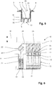
- Fig. 1 shows a three-dimensional view of a cartridge 1 according to the present invention.
- the cartridge 1 comprises a housing 2 with an outside surface 3. Further, the cartridge comprises eight reaction wells 4 (of which only one is marked with reference numerals) which are arranged on the outside surface 3 of the housing 2. Each reaction well 4 may be used to carry out a chemical or biological assay. While the embodiment of the cartridge 1 shown has eight reaction wells 4, any number of reaction wells 4 may be present depending on the intended use of the cartridge 1.
- Each reaction well 4 is open towards the outside surface 3, specifically towards the top surface, of the housing 2, such that the reaction wells 4 may be accessed, e.g. to fill a liquid into said reaction wells 4.
- reaction wells 4 include a sealing lip 11 which protrudes from said outside surface 3. The function of said sealing lip 11 is explained in connection with Fig. 6 .
- Each reaction well may comprise a coating with at least one chemical or biological agent suitable to bind to a component to assay the presence of said component in a probe.
- Said component preferably is an analyte, protein, nucleic acid and/or infectious agent.
- each reaction well 4 is suitable to carry out a specific chemical or biological assay.
- All reaction wells 4 of the cartridge may comprise a coating with the same at least one chemical or biological agent.
- the reaction wells 4 may comprise coatings with at least one different chemical or biological agent, such that two or more different types of assays may be carried out with one cartridge 1.
- the reaction wells 4 may not contain any coating, but are rather configured to act as receptacle for a probe and at least one reagent solution.
- the cartridge 1 in the embodiment as shown further includes five solution storage vessels 5 as well as a wash solution storage vessel 6.
- the solution storage vessels 5 are provided in a cylindrical shape while the wash solution storage vessel 6 is larger than said solution storage vessels 5 and has a cross-section in the form of a rhomboid. Hence, the wash solution storage vessel 6 has a larger volume than said solution storage vessels 5.
- the solution storage vessels 5 are filed with different reaction solutions and dilution solutions while the wash solution storage vessel 6 is filled with a wash solution or wash buffer.
- the reaction solutions, dilution solutions and the wash solution are used for carrying out assays in the reaction wells 4.
- the number of the solution storage vessels 5 may be varied according to the number of solutions needed for the assays.
- a cartridge 1 may also comprise more than one wash solution storage vessel 6, for example if different assays needing different wash solutions may be carried out in the reaction wells 4.
- the cartridge further comprises a barcode 7 which may be read by an appropriate sensor or reader of sais device.
- the barcode 7 may be of the one or of the two dimensional type. Alternatively, barcode 7 may be replaced by an RFID tag or the like.
- Fig. 2 shows the cartridge 1 of Fig. 1 from above.
- the reaction wells 4 have a flat bottom surface 8 onto which a coated area 9 comprising a coating of at least one chemical or biological agent is arranged.
- the coating area 9 is offset from said bottom surface 8 in a vertical direction.
- each reaction well 4 comprises two openings 10 which allow to selectively bring each reaction well 4 into fluid communication with a waste tank located beneath said reaction wells 4, as shown in Fig. 3 .
- the openings 10 are dimensioned such that entry of a liquid into said openings 10 is prevented by action of the surface tension of the liquid.
- the cross-section of the reaction wells 4 of the embodiment shown may be seen.
- the reaction wells 4 have an essentially rectangular cross-section, wherein one side of the rectangle is configured as arc.
- Fig. 3 shows a cross section of the cartridge 1 of Fig. 1 .
- a waste tank 13 is arranged beneath each reaction well 4.
- the waste tanks 13 are arranged within the housing 2 of the cartridge 1.
- a duct 12 is present below each opening 10, said ducts 12 protruding into the respective waste tank 13 lying beneath the reaction well 4.
- the ducts 12 prevent any backflow of a liquid present in a waste tank 13 into a reaction well 4.
- the coated areas 9 are slightly offset from the bottom surfaces 8 of the reaction wells 4. This facilitates the drainage of liquid out of said coated area 9 and into the openings 10.
- reaction well 4 Through the action of a pressure applied on a liquid present in any of the reaction wells 4, the liquid is pushed through the respective openings 10 and via the ducts 12 into the waste tank. Hence, through an overpressure in a reaction well 4, said reaction well 4 may be emptied from any liquid present therein.
- Fig. 4 shows an exploded view of the cartridge according to Fig. 1 .
- the reaction wells 4 are produced as a separate insert 14 which may be permanently attached to the housing 2 of the cartridge 1, e.g. by means of an irreversible snap-fit connection, welding, gluing or the like. Therefore, the housing 2 with the waste tanks 13, the solution storage vessels 5 and the wash solution storage vessel 6 as well as the insert 14 may be produced as separate parts, e.g. by means of injection moulding and later assembled.
- the coating may be applied to the coated areas 9 of the reaction wells 4 either prior or after assembly of the insert 14 to the housing 2.
- Fig. 5 shows an enlarged detailed view of a reaction well 4.
- the reaction well 4 comprises a circumferential wall 29 and a bottom surface 8 which define a reaction well volume 29.
- a liquid probe as well as other solutions such as reaction solutions, wash solutions and/or dilution solutions may be filled.
- the reaction well 4 On the bottom surface 8 the reaction well 4 includes a slightly raised coated area 9 onto which at least one chemical or biological binding agent is bound thus forming a coating on said coated area 9.
- the reaction well 4 comprises two openings 10 on said bottom surface 8.
- the openings 10 are arranged directly adjacent to the coated area 9 in the embodiment shown.
- the openings 10 are dimensioned such that entry of a liquid is prevented by the surface tension of said liquid.
- a duct 12 is arranged directly beneath each of said openings 10. Said duct protrudes into the waste tank 13 (only shown in part) located beneath the reaction well 4. At its end located in said waste tank 13, the duct 12 has an outflow 15. Within said duct 12 is a channel 30 which connects the opening 10 with the outflow 15 such that a fluid may flow from said opening 10 to said outflow 15 through said channel 30. The diameter of the channel 30 increases from said opening 10 towards said outflow 15. This prevents clogging of the channel 30, especially by clots of red blood cells.
- a device 16 according to the present invention is shown in Fig. 6 .
- the device 16 is only exemplarily depicted in this drawing.
- the device 16 may comprise a housing as well as a control element with at least one microprocessor, input means, e.g. in the form of buttons, a keyboard and/or a touchscreen display.
- the device 16 includes an actuator 18 and a fluid delivery tool 17 mounted on said actuator 18.
- the actuator 18 moves the fluid delivery tool 17 at least in a vertical direction, which is exemplarily shown as double arrow on the drawing.
- the actuator 18 moves the fluid delivery tool 17 additionally in further spatial directions.
- the actuator 18 moves the fluid delivery tool 17 in three spatial directions.
- the actuator 18 may further comprise additional elements not shown in this drawing, e.g. such as a pipette, a camera, etc.
- the actuator is preferably realized as gantry robot.
- the device further comprises at least one area 19 onto which a cartridge 1 is removably arranged in a defined position and orientation.
- the area 19 may comprises means (not shown) to lock the cartridge in the defined position and orientation, e.g. means of the form-fit or interference-fit type.
- the cartridge may be locked on said area 19 by means of a snap fit connection or the like.
- the device 16 may comprise any suitable number of areas 19. As such, the device 16 may be adapted to different throughput of assays as needed.
- the fluid delivery tool 17 comprises apertures 31, each aperture 31 including a dispensing nozzle 26 for delivering a fluid into the at least one reaction well 4 of the cartridge 1.
- the number of apertures 31 corresponds to the number of reaction wells 4 of the cartridge 1 in the embodiment as shown.
- the fluid delivery tool 16 may comprise fewer apertures 31 than the number of reaction wells 4.
- the fluid delivery tool 16 may be moved by means of the actuator 18 from one reaction well 4 to another reaction well 4.
- Each aperture 31 comprises a nose 27 which contacts a sealing lip 11 of the respective reaction well 4, such as to form a tight connection, especially an airtight connection. In order to bring the nose 27 into contact with the sealing lip 11, the fluid delivery tool 16 is lowered onto the cartridge 1 by means of the actuator.
- the apertures 31 are dimensioned such that they do not protrude into the reaction wells 4, i.e. no element of the apertures 31, such as the dispensing nozzles 26 penetrate into the reaction well volume 28.
- the fluid delivery tool 16 comprises a fluid pump in the form of a peristaltic pump 20 which is connected to the dispensing nozzles 27 of the apertures 31 by means of a conduit 24.
- a valve 25 is arranged between the conduit 24 and each dispensing nozzle 27.
- the fluid dispensing tool 16 comprises needle 21 with which a wash solution 22 may be aspirated from said wash solution storage vessel 6 by means of said peristaltic pump 20. Further, the fluid dispensing tool 16 comprises an inlet 23 with which air may be aspirated by said peristaltic pump 20.
- the peristaltic pump 20 includes a switching valve (not shown), with which either a wash solution 22 may be aspirated through the needle 21 or air aspirated through the inlet 23.
- inlet 23 may be connected to another fluid source, such as a gas bottle or a liquid reservoir, such as a flask or the like.
- wash solution 22 is first aspirated by the peristaltic pump 20 via the needle 21 and conveyed through the conduit 24 to the dispensing nozzle 26 of the aperture 31 corresponding to the reaction well 4 to be washed.
- the appropriate valves 25 it is possible to convey wash solution 22 to more than one reaction well 4 simultaneously.
- the peristaltic pump 20 is switched off. After a predetermined incubation time, the peristaltic pump conveys air from the inlet 23 through the conduit 24 to the dispensing nozzle 26 of the aperture 31 corresponding to the reaction well 4.
- Fig. 7 shows a schematic cross section of a further embodiment of a fluid delivery tool 17 used in a device or method with a cartridge 1 according to the present invention.
- the fluid delivery device 17 comprises an actuation element 32 which moves the needle 21 relative to a fluid delivery device housing 39.
- the needle 21 has been moved away of the fluid delivery tool housing 39 such as to be inserted into the wash solution storage vessel 6 of the cartridge 1.
- the actuation element comprises an arm 33 which is attached to the fluid delivery tool housing 39 and to which the needle 21 is affixed.
- the arm 33 is attached in a rotatable manner to the fluid delivery tool housing 39 by means of an attachment hinge 36.
- a drive (not shown) is provided in order to move the needle 21 relative to the fluid delivery tool housing 39.
- the needle 21 is fluidly connected to the peristaltic pump 20 of the fluid delivery tool 17 by means of a flexible conduit 38.
- Fig. 8 is a top view of the embodiment as shown in Fig. 7 .
- the arm 33 is divided into two sections 34.1, 34.2 which are rotatably connected together by means of an arm hinge 37.
- a linear movement of the needle 21 away of the fluid delivery tool housing 39 is followed by a widening of the angle between a first section 34.1 and a second section 34.2 of the arm 33 as well as of the angle between the first section 34.1 of the arm 33 and the fluid delivery tool housing 39.
- the rotation axis of the attachment hinge 36 and of the arm hinge 37 are arranged vertical relative to the surface of the housing of the cartridge 1 which is arranged on top, i.e. the axes are oriented in the direction of view in Fig. 8 .
- the arm 33 therefore allows a movement of the needle 21 only in two directions x,y as marked by the double arrows in the figure.
- Figs. 9 and 10 show the embodiment according to Figs. 7 and 8 where the needle 21 is in a position which is nearer relative to the fluid delivery device housing 39. In this situation, the needle 21 is inserted into a solution storage vessel 5 of the cartridge 1.
- both sections 34.1, 34.2 of the arm 33 are close together, whereby the angle between the fluid delivery tool housing 39 and the first section 34.1 as well as the angle between the first section 34.1 and the second section 34.2 of the arm 33 is close to 0°.
Landscapes
- Chemical & Material Sciences (AREA)
- Health & Medical Sciences (AREA)
- General Health & Medical Sciences (AREA)
- Analytical Chemistry (AREA)
- Clinical Laboratory Science (AREA)
- Chemical Kinetics & Catalysis (AREA)
- Life Sciences & Earth Sciences (AREA)
- Biochemistry (AREA)
- Physics & Mathematics (AREA)
- General Physics & Mathematics (AREA)
- Immunology (AREA)
- Pathology (AREA)
- Hematology (AREA)
- Medicinal Chemistry (AREA)
- Automatic Analysis And Handling Materials Therefor (AREA)
Claims (5)
- Kartusche (1) mit einem Gehäuse (2) und zumindest einer, in einer Außenseite des Gehäuses (2) angeordneten Reaktionsmulde (4) für einen chemischen oder biologischen Assay, wobei die zumindest eine Reaktionsmulde (4) eine Unterseite (8) aufweist, die vorzugsweise mit zumindest einem chemischen oder biologischen Bindemittel beschichtet ist, das zur Bindung an eine Komponente zum Prüfen auf das Vorhandensein einer Komponente in einer Probe geeignet ist, wobei die Kartusche (1) ferner zumindest ein Vorratsgefäß (5, 6) umfasst, das im Gehäuse (2) angeordnet ist, wobei das zumindest eine Vorratsgefäß (5, 6) eine Reagenzlösung, Waschlösung und/oder Verdünnungslösung in einer zur Durchführung des Assays in der zumindest einen Reaktionsmulde (4) ausreichenden Menge umfasst, wobei die Anzahl der Vorratsgefäße (5, 6) der Kartusche (1) derart gewählt ist, dass alle Reagenzlösungen, Waschlösungen und/oder Verdünnungslösungen, die zur Durchführung des Assays in der zumindest einen Reaktionsmulde (4) benötigt werden, in der Kartusche (1) vorhanden sind, wobei die Kartusche (1) ferner einen Abfallbehälter (13) umfasst, der unter der zumindest einen Reaktionsmulde (4) angeordnet ist, wobei die zumindest eine Reaktionsmulde (4) zumindest eine Öffnung (10) an der Unterseite (8) umfasst, mit der die Reaktionsmulde (4) selektiv mit dem Abfallbehälter (13) in Fluidverbindung gebracht werden kann, vorzugsweise durch ein Betätigungsmittel, dadurch gekennzeichnet, dass die zumindest eine Öffnung (10) mit einem Kanal (12) verbunden ist, der zu dem zumindest einen Abfallbehälter (13) führt oder in diesen hinein ragt, wobei der Kanal (12) einen Ablauf (15) aufweist, der die Abgabe einer Flüssigkeit in den zumindest einen Abfallbehälter (13) erlaubt, wobei en Durchmesser des Kanals (12) von der Öffnung (10) zum Ablauf (15) zunimmt.
- Kartusche (1) nach Anspruch 1, dadurch gekennzeichnet, dass die zumindest eine Öffnung (10) einen maximalen Durchmesser aufweist, der derart gewählt ist, dass eine Strömung einer Flüssigkeit durch die Öffnung (10) von der jeweiligen Reaktionsmulde (4) zum Abfallbehälter (13) durch eine Oberflächenspannung der Flüssigkeit verhindert wird und eine Strömung der Flüssigkeit durch Aufbringen eines Überdrucks in der Reaktionsmulde (4) und/oder eines Unterdrucks im Abfallbehälter (13), um die Flüssigkeit aus der Reaktionsmulde (4) in den Abfallbehälter (13) zu drücken und/oder zu saugen, ermöglicht werden kann.
- Kartusche (1) nach Anspruch 1, dadurch gekennzeichnet, dass die zumindest eine Öffnung (10) ein Verschlusselement umfasst, das aus einer geschlossenen Stellung, in der eine Strömung einer Flüssigkeit aus der jeweiligen Reaktionsmulde (4) zum Abfallbehälter (13) verhindert wird, in eine offene Stellung, in der die Flüssigkeitsströmung aus der jeweiligen Reaktionsmulde (4) zum Abfallbehälter (13) erlaubt ist, durch das Betätigungsmittel bewegt werden kann.
- Kartusche (1) nach Anspruch 3, dadurch gekennzeichnet, dass das Betätigungsmittel ein Betätigungszapfen ist, der mit dem Verschlusselement verbunden ist und vom Gehäuse (2) der Kartusche (1) vorragt, wobei der Betätigungszapfen beweglich ist, um das Verschlusselement aus der geschlossenen Stellung in die offene Stellung und umgekehrt zu bewegen.
- Verfahren zum Entleeren einer Flüssigkeit aus zumindest einer Reaktionsmulde (4) einer Kartusche (1) nach Anspruch 1, wobei die zumindest eine Reaktionsmulde (4) zumindest eine an einer Unterseite (8) angeordnete Öffnung (10) aufweist, mit der die Reaktionsmulde (4) selektiv mit einem Abfallbehälter (13) der Kartusche (1) in Fluidverbindung gebracht werden kann, umfassend die folgenden Schritte:a) Anordnen der Kartusche (1) an einem Bereich einer Vorrichtung (16) zur automatischen Durchführung chemischer oder biologischer Assays in einer vorgegebenen Definition und Orientierung; undb) Bewegen eines Fluidabgabewerkzeugs (17) mit zumindest einer Öffnung (31) über der Kartusche (1) mit mindestens einem Betätigungselement (18) der Vorrichtung (16), so dass die zumindest eine Öffnung (31) sich über zumindest einer Reaktionsmulde (4) befindet, undc) Abgeben zumindest einer Gasströmung durch die Öffnung (31) in die Reaktionsmulde (4), um die Flüssigkeit durch die zumindest eine Öffnung (10) in den Abfallbehälter (13) auszublasen.
Priority Applications (4)
| Application Number | Priority Date | Filing Date | Title |
|---|---|---|---|
| ES17186921T ES2781880T3 (es) | 2017-08-18 | 2017-08-18 | Cartucho para ensayos químicos o biológicos |
| EP17186921.7A EP3444033B1 (de) | 2017-08-18 | 2017-08-18 | Kartusche für chemische oder biologische assays |
| PCT/EP2018/070187 WO2019034384A1 (en) | 2017-08-18 | 2018-07-25 | CARTRIDGE AND DEVICE FOR CHEMICAL OR BIOLOGICAL ASSAYS |
| US16/639,349 US20210031181A1 (en) | 2017-08-18 | 2018-07-25 | Cartridge and device for chemical or biological assays |
Applications Claiming Priority (1)
| Application Number | Priority Date | Filing Date | Title |
|---|---|---|---|
| EP17186921.7A EP3444033B1 (de) | 2017-08-18 | 2017-08-18 | Kartusche für chemische oder biologische assays |
Publications (2)
| Publication Number | Publication Date |
|---|---|
| EP3444033A1 EP3444033A1 (de) | 2019-02-20 |
| EP3444033B1 true EP3444033B1 (de) | 2020-01-08 |
Family
ID=59655989
Family Applications (1)
| Application Number | Title | Priority Date | Filing Date |
|---|---|---|---|
| EP17186921.7A Active EP3444033B1 (de) | 2017-08-18 | 2017-08-18 | Kartusche für chemische oder biologische assays |
Country Status (4)
| Country | Link |
|---|---|
| US (1) | US20210031181A1 (de) |
| EP (1) | EP3444033B1 (de) |
| ES (1) | ES2781880T3 (de) |
| WO (1) | WO2019034384A1 (de) |
Families Citing this family (2)
| Publication number | Priority date | Publication date | Assignee | Title |
|---|---|---|---|---|
| CN112619718B (zh) * | 2020-11-17 | 2022-06-14 | 浙江省海洋水产研究所 | 一种免开盖离心管 |
| KR102346703B1 (ko) * | 2021-06-29 | 2022-01-04 | 에스디바이오센서 주식회사 | 외측 챔버와 내측 챔버가 결합된 이중 챔버 구조의 유전체 추출 장치 |
Family Cites Families (11)
| Publication number | Priority date | Publication date | Assignee | Title |
|---|---|---|---|---|
| US4090850A (en) * | 1976-11-01 | 1978-05-23 | E. R. Squibb & Sons, Inc. | Apparatus for use in radioimmunoassays |
| US4704255A (en) * | 1983-07-15 | 1987-11-03 | Pandex Laboratories, Inc. | Assay cartridge |
| US4902481A (en) * | 1987-12-11 | 1990-02-20 | Millipore Corporation | Multi-well filtration test apparatus |
| US6083761A (en) * | 1996-12-02 | 2000-07-04 | Glaxo Wellcome Inc. | Method and apparatus for transferring and combining reagents |
| JP4346893B2 (ja) * | 2002-11-01 | 2009-10-21 | 株式会社日立製作所 | 化学反応装置 |
| EP1650570B1 (de) | 2003-07-17 | 2021-05-26 | LSI Medience Corporation | Gerät zur verwendung zur messung einer komponente, die in einer probe enthalten ist, die ein messgerät und eine kartusche enthält |
| AU2012202574B2 (en) * | 2005-12-21 | 2015-11-12 | Meso Scale Technologies, Llc | Assay Apparatuses, Methods and Reagents |
| CN104297507B (zh) * | 2007-10-02 | 2017-10-10 | 赛拉诺斯股份有限公司 | 模块化现场护理装置及其应用 |
| CN102016540A (zh) | 2008-04-11 | 2011-04-13 | 梅索斯卡莱科技公司 | 分析装置、方法和试剂 |
| GB201119521D0 (en) | 2011-11-11 | 2011-12-21 | Axis Shield Asa | Assay cartridge |
| US9075042B2 (en) | 2012-05-15 | 2015-07-07 | Wellstat Diagnostics, Llc | Diagnostic systems and cartridges |
-
2017
- 2017-08-18 ES ES17186921T patent/ES2781880T3/es active Active
- 2017-08-18 EP EP17186921.7A patent/EP3444033B1/de active Active
-
2018
- 2018-07-25 WO PCT/EP2018/070187 patent/WO2019034384A1/en active Application Filing
- 2018-07-25 US US16/639,349 patent/US20210031181A1/en active Pending
Non-Patent Citations (1)
| Title |
|---|
| None * |
Also Published As
| Publication number | Publication date |
|---|---|
| US20210031181A1 (en) | 2021-02-04 |
| EP3444033A1 (de) | 2019-02-20 |
| WO2019034384A1 (en) | 2019-02-21 |
| ES2781880T3 (es) | 2020-09-08 |
Similar Documents
| Publication | Publication Date | Title |
|---|---|---|
| US7250303B2 (en) | Chemistry system for a clinical analyzer | |
| EP2817606B1 (de) | Gerät zur vorbehandlung von zellproben | |
| US7998751B2 (en) | Method and apparatus for aspirating and dispensing small liquid samples in an automated clinical analyzer | |
| EP2546655B1 (de) | Werkzeug und verfahren zur automatischen verarbeitung flüssiger proben | |
| US7666355B2 (en) | Automated analyzer | |
| US9128072B2 (en) | Apparatus for automatically performing analyses | |
| JP2004301843A (ja) | 固定多機能プローブを有する分析装置 | |
| KR101206465B1 (ko) | 분석기와, 샘플 분석 방법과, 구성요소 이송 방법 및 제조품 | |
| EP3444033B1 (de) | Kartusche für chemische oder biologische assays | |
| EP1464964B1 (de) | Testelemente-Halter mit Sonden-Führung für einen Analysator | |
| US10010885B2 (en) | Reagent dispensers, dispensing apparatus, and methods | |
| BRPI0712407A2 (pt) | dispositivo de acondicionamento para análise biológica, processo de análise biológica e autÈmato de análise biológica | |
| JP2004520594A (ja) | 微生物アナライザにおける抗生物質感受性読み取り中の光学干渉を最小限にする方法 | |
| JPH0835971A (ja) | ピペット |
Legal Events
| Date | Code | Title | Description |
|---|---|---|---|
| PUAI | Public reference made under article 153(3) epc to a published international application that has entered the european phase |
Free format text: ORIGINAL CODE: 0009012 |
|
| STAA | Information on the status of an ep patent application or granted ep patent |
Free format text: STATUS: THE APPLICATION HAS BEEN PUBLISHED |
|
| AK | Designated contracting states |
Kind code of ref document: A1 Designated state(s): AL AT BE BG CH CY CZ DE DK EE ES FI FR GB GR HR HU IE IS IT LI LT LU LV MC MK MT NL NO PL PT RO RS SE SI SK SM TR |
|
| AX | Request for extension of the european patent |
Extension state: BA ME |
|
| RIN1 | Information on inventor provided before grant (corrected) |
Inventor name: YANEZ, ANTONIO LORENZO Inventor name: RODONI, MICHELE Inventor name: MOUCHET, MARC Inventor name: JERMANN, THOMAS Inventor name: ZUMBACH, MELCHIOR |
|
| STAA | Information on the status of an ep patent application or granted ep patent |
Free format text: STATUS: REQUEST FOR EXAMINATION WAS MADE |
|
| STAA | Information on the status of an ep patent application or granted ep patent |
Free format text: STATUS: EXAMINATION IS IN PROGRESS |
|
| 17P | Request for examination filed |
Effective date: 20190506 |
|
| RBV | Designated contracting states (corrected) |
Designated state(s): AL AT BE BG CH CY CZ DE DK EE ES FI FR GB GR HR HU IE IS IT LI LT LU LV MC MK MT NL NO PL PT RO RS SE SI SK SM TR |
|
| 17Q | First examination report despatched |
Effective date: 20190522 |
|
| GRAP | Despatch of communication of intention to grant a patent |
Free format text: ORIGINAL CODE: EPIDOSNIGR1 |
|
| STAA | Information on the status of an ep patent application or granted ep patent |
Free format text: STATUS: GRANT OF PATENT IS INTENDED |
|
| RIC1 | Information provided on ipc code assigned before grant |
Ipc: G01N 33/50 20060101ALN20190709BHEP Ipc: B01L 3/00 20060101AFI20190709BHEP Ipc: G01N 35/10 20060101ALI20190709BHEP |
|
| INTG | Intention to grant announced |
Effective date: 20190801 |
|
| RIC1 | Information provided on ipc code assigned before grant |
Ipc: B01L 3/00 20060101AFI20190719BHEP Ipc: G01N 35/10 20060101ALI20190719BHEP Ipc: G01N 33/50 20060101ALN20190719BHEP |
|
| GRAS | Grant fee paid |
Free format text: ORIGINAL CODE: EPIDOSNIGR3 |
|
| GRAA | (expected) grant |
Free format text: ORIGINAL CODE: 0009210 |
|
| STAA | Information on the status of an ep patent application or granted ep patent |
Free format text: STATUS: THE PATENT HAS BEEN GRANTED |
|
| AK | Designated contracting states |
Kind code of ref document: B1 Designated state(s): AL AT BE BG CH CY CZ DE DK EE ES FI FR GB GR HR HU IE IS IT LI LT LU LV MC MK MT NL NO PL PT RO RS SE SI SK SM TR |
|
| REG | Reference to a national code |
Ref country code: GB Ref legal event code: FG4D |
|
| REG | Reference to a national code |
Ref country code: CH Ref legal event code: EP |
|
| REG | Reference to a national code |
Ref country code: DE Ref legal event code: R096 Ref document number: 602017010590 Country of ref document: DE |
|
| REG | Reference to a national code |
Ref country code: IE Ref legal event code: FG4D |
|
| REG | Reference to a national code |
Ref country code: AT Ref legal event code: REF Ref document number: 1222031 Country of ref document: AT Kind code of ref document: T Effective date: 20200215 |
|
| REG | Reference to a national code |
Ref country code: CH Ref legal event code: NV Representative=s name: KELLER AND PARTNER PATENTANWAELTE AG, CH |
|
| REG | Reference to a national code |
Ref country code: NL Ref legal event code: MP Effective date: 20200108 |
|
| REG | Reference to a national code |
Ref country code: LT Ref legal event code: MG4D |
|
| PG25 | Lapsed in a contracting state [announced via postgrant information from national office to epo] |
Ref country code: PT Free format text: LAPSE BECAUSE OF FAILURE TO SUBMIT A TRANSLATION OF THE DESCRIPTION OR TO PAY THE FEE WITHIN THE PRESCRIBED TIME-LIMIT Effective date: 20200531 Ref country code: NO Free format text: LAPSE BECAUSE OF FAILURE TO SUBMIT A TRANSLATION OF THE DESCRIPTION OR TO PAY THE FEE WITHIN THE PRESCRIBED TIME-LIMIT Effective date: 20200408 Ref country code: FI Free format text: LAPSE BECAUSE OF FAILURE TO SUBMIT A TRANSLATION OF THE DESCRIPTION OR TO PAY THE FEE WITHIN THE PRESCRIBED TIME-LIMIT Effective date: 20200108 Ref country code: LT Free format text: LAPSE BECAUSE OF FAILURE TO SUBMIT A TRANSLATION OF THE DESCRIPTION OR TO PAY THE FEE WITHIN THE PRESCRIBED TIME-LIMIT Effective date: 20200108 Ref country code: RS Free format text: LAPSE BECAUSE OF FAILURE TO SUBMIT A TRANSLATION OF THE DESCRIPTION OR TO PAY THE FEE WITHIN THE PRESCRIBED TIME-LIMIT Effective date: 20200108 Ref country code: NL Free format text: LAPSE BECAUSE OF FAILURE TO SUBMIT A TRANSLATION OF THE DESCRIPTION OR TO PAY THE FEE WITHIN THE PRESCRIBED TIME-LIMIT Effective date: 20200108 |
|
| PG25 | Lapsed in a contracting state [announced via postgrant information from national office to epo] |
Ref country code: IS Free format text: LAPSE BECAUSE OF FAILURE TO SUBMIT A TRANSLATION OF THE DESCRIPTION OR TO PAY THE FEE WITHIN THE PRESCRIBED TIME-LIMIT Effective date: 20200508 Ref country code: GR Free format text: LAPSE BECAUSE OF FAILURE TO SUBMIT A TRANSLATION OF THE DESCRIPTION OR TO PAY THE FEE WITHIN THE PRESCRIBED TIME-LIMIT Effective date: 20200409 Ref country code: BG Free format text: LAPSE BECAUSE OF FAILURE TO SUBMIT A TRANSLATION OF THE DESCRIPTION OR TO PAY THE FEE WITHIN THE PRESCRIBED TIME-LIMIT Effective date: 20200408 Ref country code: LV Free format text: LAPSE BECAUSE OF FAILURE TO SUBMIT A TRANSLATION OF THE DESCRIPTION OR TO PAY THE FEE WITHIN THE PRESCRIBED TIME-LIMIT Effective date: 20200108 Ref country code: SE Free format text: LAPSE BECAUSE OF FAILURE TO SUBMIT A TRANSLATION OF THE DESCRIPTION OR TO PAY THE FEE WITHIN THE PRESCRIBED TIME-LIMIT Effective date: 20200108 Ref country code: HR Free format text: LAPSE BECAUSE OF FAILURE TO SUBMIT A TRANSLATION OF THE DESCRIPTION OR TO PAY THE FEE WITHIN THE PRESCRIBED TIME-LIMIT Effective date: 20200108 |
|
| REG | Reference to a national code |
Ref country code: ES Ref legal event code: FG2A Ref document number: 2781880 Country of ref document: ES Kind code of ref document: T3 Effective date: 20200908 |
|
| REG | Reference to a national code |
Ref country code: CH Ref legal event code: PFA Owner name: CTC ANALYTICS AG, CH Free format text: FORMER OWNER: CTC ANALYTICS AG, CH |
|
| REG | Reference to a national code |
Ref country code: DE Ref legal event code: R097 Ref document number: 602017010590 Country of ref document: DE |
|
| PG25 | Lapsed in a contracting state [announced via postgrant information from national office to epo] |
Ref country code: DK Free format text: LAPSE BECAUSE OF FAILURE TO SUBMIT A TRANSLATION OF THE DESCRIPTION OR TO PAY THE FEE WITHIN THE PRESCRIBED TIME-LIMIT Effective date: 20200108 Ref country code: SK Free format text: LAPSE BECAUSE OF FAILURE TO SUBMIT A TRANSLATION OF THE DESCRIPTION OR TO PAY THE FEE WITHIN THE PRESCRIBED TIME-LIMIT Effective date: 20200108 Ref country code: CZ Free format text: LAPSE BECAUSE OF FAILURE TO SUBMIT A TRANSLATION OF THE DESCRIPTION OR TO PAY THE FEE WITHIN THE PRESCRIBED TIME-LIMIT Effective date: 20200108 Ref country code: RO Free format text: LAPSE BECAUSE OF FAILURE TO SUBMIT A TRANSLATION OF THE DESCRIPTION OR TO PAY THE FEE WITHIN THE PRESCRIBED TIME-LIMIT Effective date: 20200108 Ref country code: EE Free format text: LAPSE BECAUSE OF FAILURE TO SUBMIT A TRANSLATION OF THE DESCRIPTION OR TO PAY THE FEE WITHIN THE PRESCRIBED TIME-LIMIT Effective date: 20200108 Ref country code: SM Free format text: LAPSE BECAUSE OF FAILURE TO SUBMIT A TRANSLATION OF THE DESCRIPTION OR TO PAY THE FEE WITHIN THE PRESCRIBED TIME-LIMIT Effective date: 20200108 |
|
| PLBE | No opposition filed within time limit |
Free format text: ORIGINAL CODE: 0009261 |
|
| STAA | Information on the status of an ep patent application or granted ep patent |
Free format text: STATUS: NO OPPOSITION FILED WITHIN TIME LIMIT |
|
| REG | Reference to a national code |
Ref country code: AT Ref legal event code: MK05 Ref document number: 1222031 Country of ref document: AT Kind code of ref document: T Effective date: 20200108 |
|
| 26N | No opposition filed |
Effective date: 20201009 |
|
| PG25 | Lapsed in a contracting state [announced via postgrant information from national office to epo] |
Ref country code: AT Free format text: LAPSE BECAUSE OF FAILURE TO SUBMIT A TRANSLATION OF THE DESCRIPTION OR TO PAY THE FEE WITHIN THE PRESCRIBED TIME-LIMIT Effective date: 20200108 |
|
| PG25 | Lapsed in a contracting state [announced via postgrant information from national office to epo] |
Ref country code: SI Free format text: LAPSE BECAUSE OF FAILURE TO SUBMIT A TRANSLATION OF THE DESCRIPTION OR TO PAY THE FEE WITHIN THE PRESCRIBED TIME-LIMIT Effective date: 20200108 Ref country code: PL Free format text: LAPSE BECAUSE OF FAILURE TO SUBMIT A TRANSLATION OF THE DESCRIPTION OR TO PAY THE FEE WITHIN THE PRESCRIBED TIME-LIMIT Effective date: 20200108 |
|
| PG25 | Lapsed in a contracting state [announced via postgrant information from national office to epo] |
Ref country code: MC Free format text: LAPSE BECAUSE OF FAILURE TO SUBMIT A TRANSLATION OF THE DESCRIPTION OR TO PAY THE FEE WITHIN THE PRESCRIBED TIME-LIMIT Effective date: 20200108 |
|
| PG25 | Lapsed in a contracting state [announced via postgrant information from national office to epo] |
Ref country code: LU Free format text: LAPSE BECAUSE OF NON-PAYMENT OF DUE FEES Effective date: 20200818 |
|
| REG | Reference to a national code |
Ref country code: BE Ref legal event code: MM Effective date: 20200831 |
|
| PG25 | Lapsed in a contracting state [announced via postgrant information from national office to epo] |
Ref country code: IE Free format text: LAPSE BECAUSE OF NON-PAYMENT OF DUE FEES Effective date: 20200818 Ref country code: BE Free format text: LAPSE BECAUSE OF NON-PAYMENT OF DUE FEES Effective date: 20200831 |
|
| PG25 | Lapsed in a contracting state [announced via postgrant information from national office to epo] |
Ref country code: TR Free format text: LAPSE BECAUSE OF FAILURE TO SUBMIT A TRANSLATION OF THE DESCRIPTION OR TO PAY THE FEE WITHIN THE PRESCRIBED TIME-LIMIT Effective date: 20200108 Ref country code: MT Free format text: LAPSE BECAUSE OF FAILURE TO SUBMIT A TRANSLATION OF THE DESCRIPTION OR TO PAY THE FEE WITHIN THE PRESCRIBED TIME-LIMIT Effective date: 20200108 Ref country code: CY Free format text: LAPSE BECAUSE OF FAILURE TO SUBMIT A TRANSLATION OF THE DESCRIPTION OR TO PAY THE FEE WITHIN THE PRESCRIBED TIME-LIMIT Effective date: 20200108 |
|
| PG25 | Lapsed in a contracting state [announced via postgrant information from national office to epo] |
Ref country code: MK Free format text: LAPSE BECAUSE OF FAILURE TO SUBMIT A TRANSLATION OF THE DESCRIPTION OR TO PAY THE FEE WITHIN THE PRESCRIBED TIME-LIMIT Effective date: 20200108 Ref country code: AL Free format text: LAPSE BECAUSE OF FAILURE TO SUBMIT A TRANSLATION OF THE DESCRIPTION OR TO PAY THE FEE WITHIN THE PRESCRIBED TIME-LIMIT Effective date: 20200108 |
|
| P01 | Opt-out of the competence of the unified patent court (upc) registered |
Effective date: 20230515 |
|
| PGFP | Annual fee paid to national office [announced via postgrant information from national office to epo] |
Ref country code: IT Payment date: 20230830 Year of fee payment: 7 Ref country code: GB Payment date: 20230830 Year of fee payment: 7 Ref country code: CH Payment date: 20230902 Year of fee payment: 7 |
|
| PGFP | Annual fee paid to national office [announced via postgrant information from national office to epo] |
Ref country code: FR Payment date: 20230830 Year of fee payment: 7 Ref country code: DE Payment date: 20230823 Year of fee payment: 7 |
|
| PGFP | Annual fee paid to national office [announced via postgrant information from national office to epo] |
Ref country code: ES Payment date: 20231027 Year of fee payment: 7 |