EP3443846A1 - Tempering apparatus for chocolate and creme mass - Google Patents
Tempering apparatus for chocolate and creme mass Download PDFInfo
- Publication number
- EP3443846A1 EP3443846A1 EP18181245.4A EP18181245A EP3443846A1 EP 3443846 A1 EP3443846 A1 EP 3443846A1 EP 18181245 A EP18181245 A EP 18181245A EP 3443846 A1 EP3443846 A1 EP 3443846A1
- Authority
- EP
- European Patent Office
- Prior art keywords
- mass
- common
- tube part
- stack
- stage
- Prior art date
- Legal status (The legal status is an assumption and is not a legal conclusion. Google has not performed a legal analysis and makes no representation as to the accuracy of the status listed.)
- Granted
Links
- 238000005496 tempering Methods 0.000 title claims abstract description 35
- 235000019219 chocolate Nutrition 0.000 title claims abstract description 33
- 238000001816 cooling Methods 0.000 claims abstract description 64
- XLYOFNOQVPJJNP-UHFFFAOYSA-N water Substances O XLYOFNOQVPJJNP-UHFFFAOYSA-N 0.000 claims abstract description 58
- 238000002425 crystallisation Methods 0.000 claims abstract description 34
- 238000010438 heat treatment Methods 0.000 claims abstract description 19
- 238000002156 mixing Methods 0.000 claims abstract description 10
- 230000005484 gravity Effects 0.000 abstract description 5
- 239000013078 crystal Substances 0.000 description 40
- 244000299461 Theobroma cacao Species 0.000 description 31
- 230000008025 crystallization Effects 0.000 description 20
- 238000009529 body temperature measurement Methods 0.000 description 10
- 239000003925 fat Substances 0.000 description 10
- 235000019197 fats Nutrition 0.000 description 10
- 238000002844 melting Methods 0.000 description 9
- 238000003303 reheating Methods 0.000 description 9
- 235000019220 whole milk chocolate Nutrition 0.000 description 9
- 235000019625 fat content Nutrition 0.000 description 8
- 230000008018 melting Effects 0.000 description 8
- 229940110456 cocoa butter Drugs 0.000 description 7
- 235000019868 cocoa butter Nutrition 0.000 description 7
- 238000004519 manufacturing process Methods 0.000 description 6
- 229910001018 Cast iron Inorganic materials 0.000 description 3
- 239000000470 constituent Substances 0.000 description 3
- 230000000694 effects Effects 0.000 description 3
- 238000000034 method Methods 0.000 description 3
- 235000015145 nougat Nutrition 0.000 description 3
- 230000002028 premature Effects 0.000 description 3
- 238000003860 storage Methods 0.000 description 3
- 150000001875 compounds Chemical class 0.000 description 2
- 235000019221 dark chocolate Nutrition 0.000 description 2
- 239000007788 liquid Substances 0.000 description 2
- 239000003346 palm kernel oil Substances 0.000 description 2
- 235000019865 palm kernel oil Nutrition 0.000 description 2
- 230000001105 regulatory effect Effects 0.000 description 2
- 239000007787 solid Substances 0.000 description 2
- 239000000725 suspension Substances 0.000 description 2
- 206010037660 Pyrexia Diseases 0.000 description 1
- 235000009470 Theobroma cacao Nutrition 0.000 description 1
- 238000004140 cleaning Methods 0.000 description 1
- 239000000498 cooling water Substances 0.000 description 1
- 230000003292 diminished effect Effects 0.000 description 1
- 238000010616 electrical installation Methods 0.000 description 1
- 238000005265 energy consumption Methods 0.000 description 1
- 235000013861 fat-free Nutrition 0.000 description 1
- 238000002955 isolation Methods 0.000 description 1
- 235000013336 milk Nutrition 0.000 description 1
- 239000008267 milk Substances 0.000 description 1
- 210000004080 milk Anatomy 0.000 description 1
- 239000003921 oil Substances 0.000 description 1
- 239000002245 particle Substances 0.000 description 1
- 239000000843 powder Substances 0.000 description 1
- 238000004886 process control Methods 0.000 description 1
- 235000019222 white chocolate Nutrition 0.000 description 1
Images


Classifications
-
- A—HUMAN NECESSITIES
- A23—FOODS OR FOODSTUFFS; TREATMENT THEREOF, NOT COVERED BY OTHER CLASSES
- A23G—COCOA; COCOA PRODUCTS, e.g. CHOCOLATE; SUBSTITUTES FOR COCOA OR COCOA PRODUCTS; CONFECTIONERY; CHEWING GUM; ICE-CREAM; PREPARATION THEREOF
- A23G1/00—Cocoa; Cocoa products, e.g. chocolate; Substitutes therefor
- A23G1/0003—Processes of manufacture not relating to composition or compounding ingredients
- A23G1/0046—Processes for conditioning chocolate masses for moulding
-
- A—HUMAN NECESSITIES
- A23—FOODS OR FOODSTUFFS; TREATMENT THEREOF, NOT COVERED BY OTHER CLASSES
- A23G—COCOA; COCOA PRODUCTS, e.g. CHOCOLATE; SUBSTITUTES FOR COCOA OR COCOA PRODUCTS; CONFECTIONERY; CHEWING GUM; ICE-CREAM; PREPARATION THEREOF
- A23G1/00—Cocoa; Cocoa products, e.g. chocolate; Substitutes therefor
- A23G1/04—Apparatus specially adapted for manufacture or treatment of cocoa or cocoa products
- A23G1/18—Apparatus for conditioning chocolate masses for moulding
-
- A—HUMAN NECESSITIES
- A23—FOODS OR FOODSTUFFS; TREATMENT THEREOF, NOT COVERED BY OTHER CLASSES
- A23G—COCOA; COCOA PRODUCTS, e.g. CHOCOLATE; SUBSTITUTES FOR COCOA OR COCOA PRODUCTS; CONFECTIONERY; CHEWING GUM; ICE-CREAM; PREPARATION THEREOF
- A23G3/00—Sweetmeats; Confectionery; Marzipan; Coated or filled products
- A23G3/02—Apparatus specially adapted for manufacture or treatment of sweetmeats or confectionery; Accessories therefor
- A23G3/0205—Manufacture or treatment of liquids, pastes, creams, granules, shred or powder
- A23G3/0226—Apparatus for conditioning, e.g. tempering, cooking, heating, cooling, boiling down, evaporating, degassing, liquefying mass before shaping
Definitions
- the present invention concerns an apparatus comprising a cooling stage and a crystallisation stage for continuous tempering of a fat-containing, crystallisable mass such as chocolate mass or creme mass, comprising a column of mass chambers and intermediary water chambers arranged in stacked elements, a central drive shaft in engagement with mixing elements arranged in the mass chambers, and which crystallisation stage is arranged in the column.
- chocolate or creme mass continuously tempered by the apparatus according to the invention encompass all types of suspensions of non-fat particles such as sugar, milk powders and cocoa solids mixed up with a liquid fat constituent, so that the suspensions are capable of crystallizing. It could be both chocolate types used in any kind of production of chocolate articles or it could be creme mass used inside articles as filling, upon or as "sandwiching" layers in articles in both production of bakery articles as well as of chocolate articles.
- the fat constituent comprises genuine cocoa butter typically in a content of up to approximately 35%.
- the fat phase may also comprise substitutes as well. A small content of up to 2-3 % of genuine cocoa butter may still be left in the recipe.
- Substitutes may be in the form of other types of fat-containing oils such as palm-kernel oil.
- Chocolate types having the cocoa butter been replaced by other fats are often named commercially as compound chocolate, especially when the cocoa butter has been replaced completely by palm-kernel oil.
- Mass made of up to 100% cocoa butter may however also be continuously tempered. It is used later on as constituent in the production of different chocolate mass recipes.
- the fat phase constitutes of genuine cocoa butter or substitutes
- the fat phase must be capable of crystallizing into stable crystal types, such as the ⁇ V-crystals developing in genuine cocoa butter.
- stable crystal types such as the ⁇ V-crystals developing in genuine cocoa butter.
- the solidified chocolate articles will also achieve the longest possible shelf life and the best resistance against bloom, as instable crystals are diminished. If there is a content of in-stable crystals left in the mass, they will give rise to shorter shelf-life as the articles will bloom more quickly as when in-stable crystals are not present.
- the prior art tempering apparatus can deliver tempered mass having a content of the stable crystal-type only, such as ⁇ V-crystals in chocolate mass. Only then, the manufacturer can rely on, that the quality of his chocolate products are consistent.
- the prior tempering apparatus of the introductory art comprise a cooling stage, a crystallization stage and a reheating stage arranged in the column.
- the stages are typically arranged each in their own separate section of the column, often separated by an isolation disc between neighboring chambers.
- Some apparatuses have the cooling and crystallization stages arranged in the same section of the column.
- all the prior art apparatuses have columns, which are high, heavy and extensive.
- the chocolate or creme mass Before the chocolate or creme mass is supplied to perform the actual tempering process it is heated to around 40-50°C in a premature step. All the crystals in the particular mass are melted out and dissolved in the mass before the mass is pumped continuously through the cooling stage of the column.
- the premature step is typically arranged distant to the tempering apparatus, the mass being heated in a storage tank. However, a premature heating step could also be arranged in the tempering column in front of the cooling stage, which then makes the column even higher.
- the chamber surfaces of the cooling and crystallisation stages are kept “cold” with temperatures typically between 8-15 °C regulated by the temperature and flow of the water in the intermediary chambers.
- the low temperatures are necessary for the heat-exchange of the cooling and crystallisation stages of the column to be as effective as possible. Otherwise, the columns would be even higher for a particular maximum capacity and mass type.
- the disadvantages of the "cold" surface temperatures in the cooling and crystallisation chambers are creation of in-stable crystals simultaneously with the creation of the stable crystals. This phenomenon is especially extensive in the cooling stage.
- the temperature of the mass is raised only slightly being sufficient for melting up again the in-stable crystals only. They are then not present in the mass any longer, however, the desirable stable crystals, such as the ⁇ V-crystals in chocolate, are still preserved.
- a high and extensive reheating stage of the column is necessary when complete re-melting of the undesirable, instable crystals must be ensured.
- a given size of a tempering machine at the market has a fixed length of the column and consequently fixed areas for cooling, crystallisation and reheating. Due to the above described problematic of continuous tempering of masses with a high fat content, it is well-known today, that the maximum capacity measured in kilograms per hour of tempered mass for a given tempering machine at the market, is lowered severely when recipes with a high fat content are tempered. The maximum capacity is achieved when tempering dark chocolate having a fat content between 20-34%. In comparison herewith the capacity is typically lowered around 20% when milk chocolate, compound chocolate, nougat or other mass with a fat content between 30% and 40% is tempered. When high fat recipes having fat content between 40% and 100% are tempered, the maximum capacity is lowered up to 50%.
- Another major disadvantage for the high columns is a very high energy consumption, firstly for cooling down the total mass and secondly for reheating the mass. Also the energy requirements are high for the chocolate pumps and the gear motors of the tempering columns.
- the center of gravity of the columns are high above the floor level, which makes the apparatus difficult and cumbersome to transport, maneuver and install in factories.
- the apparatuses When adapted for tempering of higher capacities of mass, such as typically more than 3000kg/hour, the apparatuses are so high, that they have to be tilted or laid down to horizontal during handling and transportation. This especially applies when the apparatuses are adapted for tempering of mass with high fat-content such as nougat, raw chocolate mass or chocolate liquor requiring around the double cooling capacity than dark chocolate.
- the columns constitute of heavy cast-iron elements each having a water and a mass chamber. Each element of the big columns may weight up to more than hundred kilograms. When being stacked upon each other the elements constitute the column.
- Handling and stacking of the heavy elements are difficult and time-consuming and has to be done directly on the apparatus support frame for the bigger versions. Afterwards, the high and heavy columns are difficult to handle and move around in the production environment, for example when the electrical installations has to be made in another area of the factory.
- EP0685168A1 discloses an apparatus of the introductory art by which a cooling stage A1, a crystallization stage Ak and a reheating stage A2 are arranged in the column.
- the column itself is high and heavy with the center of gravity at a high level.
- the apparatuses are then both cumbersome and difficult to build, handle and install in a chocolate production factory.
- the inventive apparatus is characterised in, that the cooling stage is arranged in a heat exchanger having at least one row of parallel plates arranged in a stack sealed at their edges providing intermediary, neighbouring channels each having an inlet and an outlet, that every second channel in the row is connected with a common first inlet and a common first outlet for the flow of mass there through, and that each of the intermittent, neighbouring channels are connected with a common second inlet and a common second outlet for the flow of water medium there through.
- the mass In the common first inlet the mass is being split into several streams when entering each second channel in the row. The mass is then flowing in a row of parallel streams through the heat exchanger, simultaneously being tempered by intermittent, neighboring channels each with water medium flowing there through.
- the inventive heat exchanger has much smaller outside dimensions than the cooling stage of a prior art column, but is however, still achieving the same cooling effect.
- the cooling stage heat exchanger fits in several places in the apparatus beside the column, so that the cooling stage is no longer part of the column itself.
- the inventive apparatus is then both smaller in size and much lower in height than the prior art apparatus.
- the weight savings are very high as the inventive plate heat exchanger typically reduces the weight of the cooling stage 200-500% in comparison with the prior art apparatus.
- the mass channels of the cooling stage heat exchanger of the inventive apparatus are free from any intermediary scrapers, discs or wings moving through the chambers such as by the cooling stages of the prior columns.
- the channels are slim in comparison to the extension of the plates.
- the row of the many parallel channels ensure that the mass is split into several "plate-like" streams, each of them all being exposed to accurately the same tempering conditions exercised by each of the intermittent, neighboring water channels.
- the inventive heat exchanger is then much more effective than a column of the same volume. When comparing length or width of the inventive cooling stage heat exchanger with diameter of the column, the inventive heat exchanger is superior.
- the plates of the row of parallel plates can have several forms such as being planar or corrugated as long as the mass is flowing in a row of parallel streams through the cooling stage heat exchanger, simultaneously being tempered by intermittent, neighboring channels each with water medium flowing there through.
- the channels When the channels have a width of 1-10 mm, the mass flow through the channels simultaneously as a row of parallel plates or sheets. Most preferably, the channels have a width of 2-5 mm, so that the mass flow through the channels as thick, separated pages in a big book. When the channels have a width of 1-2 mm the mass flow as film-like sheets or as pages in a big book.
- the cooled mass is completely homogenous and uniform in constitution and temperature when leaving the common first outlet.
- the temperature of the mass leaving the common first outlet is then controlled sharply within tenths of a degree. Consequently, the particular mass can be controlled exactly to a temperature just above the crystal-creating temperature of that mass. This is especially desirable when high-quality mass is tempered.
- No crystals are made in the mass in the cooling stage, and when the mass enters the crystallization stage of the column, very little cooling is necessary for the creation of the crystals.
- the mass is cooled in the inventive plate heat exchanger without the creation of any crystals, which then is ignited when the mass enters the crystallization stage of the column.
- no crystals are made in the inventive cooling stage - neither the desirable ⁇ V-crystals for chocolate mass, nor any lower melting crystals, such as the ⁇ IV-crystals, then is the process extremely well-controlled.
- the re-heating section is omitted. This requires, that the crystallization stage is able to create the desirable, stable crystals in the mass only, such as the the ⁇ V-crystals in chocolate mass. Creation of undesirable lower melting crystals in the mass must be avoided, otherwise the reheating section is needed.
- the crystallization stage extends over all the chambers of the column, so that the reheating section is omitted, the height and weight of the column and consequently of the inventive apparatus is the lowest possible in comparison with the prior art.
- the cooling stage heat exchanger is easy and fast to assemble and mount in the apparatus.
- the geometric cubic stack shape provides for easy fitting in of the stack in corners of the apparatus, close to the floor in the support frame of the apparatus or beside the column.
- the mass inlet tube part and the water outlet tube part are arranged at the same side of the stack, and at the opposite side of the stack are arranged both the mass outlet tube part and the water inlet tube part, then are the mass and the water flowing in opposite directions through the stack.
- the cooling stage heat exchanger stack then obtains the highest heat exchange effect or the smallest possible outer dimensions.
- the height of the inventive apparatus is reduced to the lowest possible level in comparison with the height of a prior art apparatus.
- An apparatus having a column with a pre-heating stage, a cooling stage, a crystallisation stage and a re-heating stage is the highest of all prior tempering apparatuses. For example, is the height reduced from 300 cm for the mentioned prior art apparatus and to a height of 100 cm for the inventive apparatus having the same capacities.
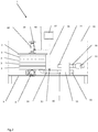
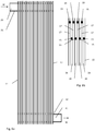
- the inventive apparatus 1 for continuous tempering of fat-containing, crystallisable mass such as chocolate mass or creme mass comprises a column 2 of stacked circular elements 3 made of cast-iron. Each element 3 has an upper mass chamber 4 and a lower water chamber 5, as disclosed in figure 11 . By the stacking of the elements 3, gaskets 6 ensures that the mass chambers 4 are closed of properly between the neighbouring elements 3. All the mass chambers 4 in the column are connected with each other by non-disclosed openings providing passage vertically through the water chambers 5.
- the water chambers 5 of the elements 3 are connected to each other in a particular crystallisation or re-heating stage. All the elements 3 in the crystallisation stage are connected to each other and to a supply of temperature controlled water. Many different layouts of water circulation systems are well-known, so these are not described in further detail.
- a central drive shaft 7 is shown schematically in part, and is driven by a gear motor 8 arranged on the frame or support 9 of the apparatus 1, as disclosed in figure 1 and 2 .
- the drive shaft 7 is in engagement with mixing elements 10 arranged in each of the mass chambers 4.
- the mixing elements 10 of the known columns are propels, discs or even planetary mixers.
- figure 11 is disclosed a commonly applied mixing propel, seen in section.
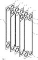
- the cooling stage of the mass tempering apparatus 1 is arranged in a heat exchanger 11 having a row of parallel plates 12 arranged in a stack 13, i.e. figures 1-6 .
- the plates 12 are mutually sealed by intermediary gaskets 15 at their neighbouring surfaces, typically close to their edges 14 or periphery, i.e. figure 5 .
- the "mass flow side" of the heat exchanger is disclosed in figure 4 .
- the arrows C represents the flow of the chocolate.
- the common first inlet 18 and the common first outlet 19 for the mass are disclosed in figure 4 in a simplified manner as blank holes. By studying figures 5 and 6 it is clearly seen, that the inlet 18 and outlet 19 for the mass are created by the holes in the plates.
- FIG. 6a The "water flow side" of the cooling stage heat exchanger is disclosed in figure 6a .
- figure 6b disclosed the intermediary, neighbouring channels 16, 17 between the plates 12.
- Every second channel 16 in the row of plates 12 are connected with the common first inlet 18 and the common first outlet 19 for the flow of mass there through.
- Each of the intermittent, neighbouring channels 17 are connected with a common second inlet 20 and a common second outlet 21 for the flow of water there through.
- FIGS. 3-6 are schematic drawings focused on disclosing the principal build-up of the inventive cooling stage in terms of understanding the inventive solution. Especially may the number of plates 12 in practice deviate from the disclosed numbers.
- the plates 12 are disclosed as being planar. However, they can have several other forms such as being corrugated or other types of depressions, as long as the mass is flowing simultaneously in a row of parallel streams being cooled by intermittent water channels through the heat exchanger.
- the stack of plates 13 is arranged in a cubic box 22 made up of side panels 23-28, which provide for easy cleaning on the outside of the heat exchanger.
- side panels 23-28 which provide for easy cleaning on the outside of the heat exchanger.
- the stack of plates and intermittent gaskets may for example be arranged on bars and squeezed together, so the channels between the plates thereby are kept tight. Side panels are then not necessary.
- the common first inlet 18 is connected with a mass inlet tube part 29 at one side 26 of the heat exchanger 11.
- the common first outlet 19 is connected with a mass outlet tube part 30 at the other side 28 of the exchanger 11, i.e. figures 3 and 4 .
- the common second inlet 20 connected with a water inlet tube part 31 arranged at the side 28 of the exchanger 11.
- the common second outlet 21 is connected with a water outlet tube part 32 arranged at the opposite side 26 of the exchanger 11.
- the arrows W depict the flow directions of the water.
- the mass and the water are in counter-flow in the heat exchanger 11 providing a highly effective heat transfer between the mass and the colder water.
- the water inlet tube part 31 and the water outlet tube part 32 are adapted to be connected with a circuit of temperature regulated water, which is not disclosed, as it is not part of the invention as such. Important only, is that the circuit continuously delivers water flow to the inlet tube part 31, so that the heat exchanger is controlled to the desired extent or level for the temperature of the mass leaving the exchanger through the mass outlet tube part 30.
- a mass pump 33 is connected to the mass inlet tube part 29 as disclosed in figure 2 .
- the pump 33 is to its suction side adapted to be connected with a non-disclosed conduit leading mass to the pump from a tank or other supply of mass.
- the mass outlet tube part 30 at the other side of the cooling stage heat exchanger 11, is via a mass conduit 34 connected with the column 2.
- a temperature measurement unit 35 is arranged in the conduit 34 and is wired 36 to a control screen 37, which in this embodiment comprises a CPU or other process control unit.
- a mass outlet conduit 38 from the column comprises a second temperature measurement unit 39, which is also wired 40 to the control screen 37.
- a dotted line 41 represents the housing of the apparatus 1 in which the control screen 37 is arranged. In figure 1 is the control screen 37 shown in its correct position in the housing 41, however, in figure 2 the screen 37 is depicted schematically above the housing 41 for the sake of clarity.
- the pump 33 runs continuously, so that the mass is feed from a storage tank and to the cooling stage heat exchanger 11.
- the mass is a chocolate mass recipe it is heated in the storage tank to a temperature of 45-50 °C.
- the mass is then free from any crystals as the temperature is then well above the highest melting temperature for crystals available in solid chocolate mass.
- the mass channels 16 of the inventive cooling stage heat exchanger 11 are free from any intermediary scrapers, discs or wings moving through the chambers such as being common in the cooling stages of the prior columns.
- the channels 16 are slim, having a width of 1-10 mm, in comparison to the extension of the plates 12.
- the row of the many parallel channels 16 ensure, that the mass is split into several "plate-like" streams, which are simultaneously exposed to accurately the same cooling conditions exercised by each of the intermittent, neighboring water channels 17.
- mass from each of the channels 16 are mixed again in the common first outlet 19, it is completely homogenous and is having the same temperature in all parts of the mass flow.
- the mass flow is mixed and cooled differently during its passage through the successive, serially connected mass chambers in the elements.
- the surface temperatures and mixing intensity of a particular mass chamber varies from center to periphery which provides for inhomogenous mass in a cooling stage.
- the channels have a width of 3 mm, so that the mass flows through the parallel channels 16 as parallel sheets or like thick pages in a big book.
- the temperature of the uniform and homogenous mass leaving the common first outlet 19 of the cooling stage heat exchanger 11, is controlled sharply within tenths of a degree.
- a desired mass temperature is pre-set at the control screen 37, and is measured continuously by the mass temperature measurement unit 35 extending into the mass in the conduit 34, which is connecting the outlet 19 and the crystallization stage in the column 2.
- the CPU or computer of the control screen 37 then controls the cooling water temperature and flow continuously being delivered to the common second inlet 20.
- the control is in accordance with the obtained mass temperature received from the unit 35, so that the cooling stage 11 removes the necessary heat from the mass for obtaining the desired pre-set mass temperature in the conduit 35.
- the pre-set temperature to be obtained at the unit 35 could be set slightly above the crystal-creation temperature.
- the temperature could be set to 27°C at the unit 35.
- the crystal-creation temperature is 26,5°C.
- a desired output temperature for the ready crystallized mass to be obtained at the second temperature measurement unit 39 is also pre-set via the control screen 37.
- the water circuit of the column 2 is controlled automatically, so that when the water flow through the chambers 5 of the elements, the mass is cooled accurately enough for obtaining the desired pre-set temperature when it is leaving the crystallization column through the output conduit 38.
- the gear motor 8 continuously revolves the shaft 7 with the mixing propels 10, thereby mixing the created crystals up into the mass.
- the inventive apparatus has a maximum capacity of 4000 kg of milk chocolate per hour.
- the cooling stage heat exchanger 11 has the dimensions of width: 500 mm and height: 250 mm.
- the horizontal depth of the exchanger 11 is measured in the stacking direction of the plates 12. It is 300 mm when 35 plates 12 are stacked with an average width of each of the channels 16 or 17 of 3 mm.
- the total effective heat exchange area of the plates 12 are then around 8 m2.
- the crystallization stage column 2 constitutes of four elements 3 each having a diameter of 650 mm.
- the crystallization stage column 2 is further controllable to such extent, that the milk chocolate mass is kept homogenous, and only a slight temperature lowering of 0,5-1,0°C through the column 2 is obtained.
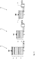
- FIG 10 is schematically disclosed a prior art column 42 having a maximum capacity of tempering 4000 kg milk chocolate per hour.
- the column 42 has a cooling stage 43 of 5 elements height, a crystallization stage 44 of 4 elements height and a re-heating stage 45 of 2 elements height.
- a total of 11 elements constitute the height of the column 42.
- In the cooling stage 43 are the mass and the water in counter-flow, and the water is cold, typically 10-14°C for providing the necessary cooling effect on the mass with that capacity. Different types of crystals are then created in especially chocolate mass, such as the milk chocolate mass. Consequently, the reheating stage 45 is necessary to melt out the undesirable, lower melting crystals again.
- the column 2 of the inventive apparatus 46 only requires a column having a height of 4 elements.
- the building height and the center of gravity of the inventive apparatus 46 is then much lower than for the prior art column 42 as seen in figure 10 .
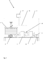
- inventive apparatus 47 having all the parts of the apparatus 1 of figures 1-6 . Furthermore, is under the housing 41 arranged a further inventive heat exchanger 48, which is used for heating up the supplied mass to a crystal-free temperature before entering the cooling stage heat exchanger 11.
- a further inventive heat exchanger 48 which is used for heating up the supplied mass to a crystal-free temperature before entering the cooling stage heat exchanger 11.
- the innovative heat exchanger 48 providing the pre-heating stage is arranged at the support 9 and preserves the low center of gravity.
- a further temperature measurement unit 49 is arranged in the tube-connection between the heat exchangers 48 and 11. The unit 49 is wired 50 to the control screen 37, so that the mass temperature is controlled to a desired level, such as 45-50°C for chocolate mass before entering the cooling stage exchanger 11.
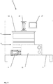
- FIG 8 and 9 are disclosed another embodiment 50 of the inventive apparatus.
- the apparatus 50 of figures 8 , 9 has an upper re-heating stage 51 arranged in further elements 3 on top of the column 2 of figures 1 and 2 .
- the column 52 of the tempering apparatus 50 then constitutes both a crystallization stage 53 and a re-heating stage 51 upon that.
- a further temperature measurement unit 54 is inserted in between the crystallization stage 53 and the re-heating stage 51 and is wired to the control screen 37. This embodiment is necessary when it is not possible to avoid undesirable crystals in the mass during its passage through the crystallization stage 53 of the column 52.
- the pre-set temperature to be achieved at the unit 39 is then set to be slightly higher than the temperature to be achieved at the unit 54 after the crystallization stage.
- the temperature could typically be 0,5-1,0°C higher at the unit 39 than at the unit 54.
- the height of the column 52 is disclosed in figure 10 for comparison with the much higher prior art column 42.
Abstract
Description
- The present invention concerns an apparatus comprising a cooling stage and a crystallisation stage for continuous tempering of a fat-containing, crystallisable mass such as chocolate mass or creme mass, comprising a column of mass chambers and intermediary water chambers arranged in stacked elements, a central drive shaft in engagement with mixing elements arranged in the mass chambers, and which crystallisation stage is arranged in the column.
- Generally, chocolate or creme mass continuously tempered by the apparatus according to the invention encompass all types of suspensions of non-fat particles such as sugar, milk powders and cocoa solids mixed up with a liquid fat constituent, so that the suspensions are capable of crystallizing. It could be both chocolate types used in any kind of production of chocolate articles or it could be creme mass used inside articles as filling, upon or as "sandwiching" layers in articles in both production of bakery articles as well as of chocolate articles. When it comes to the most widely used chocolate mass types, the fat constituent comprises genuine cocoa butter typically in a content of up to approximately 35%. However, the fat phase may also comprise substitutes as well. A small content of up to 2-3 % of genuine cocoa butter may still be left in the recipe. Substitutes may be in the form of other types of fat-containing oils such as palm-kernel oil. Chocolate types having the cocoa butter been replaced by other fats are often named commercially as compound chocolate, especially when the cocoa butter has been replaced completely by palm-kernel oil. Mass made of up to 100% cocoa butter may however also be continuously tempered. It is used later on as constituent in the production of different chocolate mass recipes.
- For the continuous tempering to be performed, it is decisive, that whether the fat phase constitutes of genuine cocoa butter or substitutes, the fat phase must be capable of crystallizing into stable crystal types, such as the βV-crystals developing in genuine cocoa butter. However, it is important to avoid instable crystals in the solidified mass. Only then, eatable chocolate articles with good taste, crisp break and shiny appearance are created. The solidified chocolate articles will also achieve the longest possible shelf life and the best resistance against bloom, as instable crystals are diminished. If there is a content of in-stable crystals left in the mass, they will give rise to shorter shelf-life as the articles will bloom more quickly as when in-stable crystals are not present.
- For the manufacturers of articles made by such masses, it is always desirable, that the prior art tempering apparatus can deliver tempered mass having a content of the stable crystal-type only, such as βV-crystals in chocolate mass. Only then, the manufacturer can rely on, that the quality of his chocolate products are consistent.
- The prior tempering apparatus of the introductory art comprise a cooling stage, a crystallization stage and a reheating stage arranged in the column. The stages are typically arranged each in their own separate section of the column, often separated by an isolation disc between neighboring chambers. Some apparatuses have the cooling and crystallization stages arranged in the same section of the column. However, all the prior art apparatuses have columns, which are high, heavy and extensive.
- Before the chocolate or creme mass is supplied to perform the actual tempering process it is heated to around 40-50°C in a premature step. All the crystals in the particular mass are melted out and dissolved in the mass before the mass is pumped continuously through the cooling stage of the column. The premature step is typically arranged distant to the tempering apparatus, the mass being heated in a storage tank. However, a premature heating step could also be arranged in the tempering column in front of the cooling stage, which then makes the column even higher.
- The chamber surfaces of the cooling and crystallisation stages are kept "cold" with temperatures typically between 8-15 °C regulated by the temperature and flow of the water in the intermediary chambers. The low temperatures are necessary for the heat-exchange of the cooling and crystallisation stages of the column to be as effective as possible. Otherwise, the columns would be even higher for a particular maximum capacity and mass type. However, the disadvantages of the "cold" surface temperatures in the cooling and crystallisation chambers are creation of in-stable crystals simultaneously with the creation of the stable crystals. This phenomenon is especially extensive in the cooling stage.
- In the reheating stage, the temperature of the mass is raised only slightly being sufficient for melting up again the in-stable crystals only. They are then not present in the mass any longer, however, the desirable stable crystals, such as the βV-crystals in chocolate, are still preserved. A high and extensive reheating stage of the column is necessary when complete re-melting of the undesirable, instable crystals must be ensured.
- When mass with high fat content such as milk chocolate, white chocolate, nougat or filling mass for pralines are tempered, then the amount of in-stable crystals created in the cooling stage is often much too high. The surfaces must be even colder for obtaining an acceptable capacity of tempered mass per hour. So, when chocolate with high fat content is tempered, then, the problems of the high columns are even more relevant
- A given size of a tempering machine at the market has a fixed length of the column and consequently fixed areas for cooling, crystallisation and reheating.
Due to the above described problematic of continuous tempering of masses with a high fat content, it is well-known today, that the maximum capacity measured in kilograms per hour of tempered mass for a given tempering machine at the market, is lowered severely when recipes with a high fat content are tempered. The maximum capacity is achieved when tempering dark chocolate having a fat content between 20-34%. In comparison herewith the capacity is typically lowered around 20% when milk chocolate, compound chocolate, nougat or other mass with a fat content between 30% and 40% is tempered. When high fat recipes having fat content between 40% and 100% are tempered, the maximum capacity is lowered up to 50%. - Another major disadvantage for the high columns is a very high energy consumption, firstly for cooling down the total mass and secondly for reheating the mass. Also the energy requirements are high for the chocolate pumps and the gear motors of the tempering columns.
- The center of gravity of the columns are high above the floor level, which makes the apparatus difficult and cumbersome to transport, maneuver and install in factories. When adapted for tempering of higher capacities of mass, such as typically more than 3000kg/hour, the apparatuses are so high, that they have to be tilted or laid down to horizontal during handling and transportation. This especially applies when the apparatuses are adapted for tempering of mass with high fat-content such as nougat, raw chocolate mass or chocolate liquor requiring around the double cooling capacity than dark chocolate. The columns constitute of heavy cast-iron elements each having a water and a mass chamber. Each element of the big columns may weight up to more than hundred kilograms. When being stacked upon each other the elements constitute the column. Handling and stacking of the heavy elements are difficult and time-consuming and has to be done directly on the apparatus support frame for the bigger versions. Afterwards, the high and heavy columns are difficult to handle and move around in the production environment, for example when the electrical installations has to be made in another area of the factory.
-
EP0685168A1 discloses an apparatus of the introductory art by which a cooling stage A1, a crystallization stage Ak and a reheating stage A2 are arranged in the column. The column itself is high and heavy with the center of gravity at a high level. The apparatuses are then both cumbersome and difficult to build, handle and install in a chocolate production factory. - The inventive apparatus is characterised in, that the cooling stage is arranged in a heat exchanger having at least one row of parallel plates arranged in a stack sealed at their edges providing intermediary, neighbouring channels each having an inlet and an outlet, that every second channel in the row is connected with a common first inlet and a common first outlet for the flow of mass there through,
and that each of the intermittent, neighbouring channels are connected with a common second inlet and a common second outlet for the flow of water medium there through. - In the common first inlet the mass is being split into several streams when entering each second channel in the row. The mass is then flowing in a row of parallel streams through the heat exchanger, simultaneously being tempered by intermittent, neighboring channels each with water medium flowing there through.
- The tempering of the parallel streams of mass is highly effective. Consequently, the inventive heat exchanger has much smaller outside dimensions than the cooling stage of a prior art column, but is however, still achieving the same cooling effect. Advantageously, the cooling stage heat exchanger fits in several places in the apparatus beside the column, so that the cooling stage is no longer part of the column itself. The inventive apparatus is then both smaller in size and much lower in height than the prior art apparatus. The weight savings are very high as the inventive plate heat exchanger typically reduces the weight of the cooling stage 200-500% in comparison with the prior art apparatus.
- The mass channels of the cooling stage heat exchanger of the inventive apparatus are free from any intermediary scrapers, discs or wings moving through the chambers such as by the cooling stages of the prior columns. The channels are slim in comparison to the extension of the plates. The row of the many parallel channels ensure that the mass is split into several "plate-like" streams, each of them all being exposed to accurately the same tempering conditions exercised by each of the intermittent, neighboring water channels. The inventive heat exchanger is then much more effective than a column of the same volume. When comparing length or width of the inventive cooling stage heat exchanger with diameter of the column, the inventive heat exchanger is superior.
- The plates of the row of parallel plates can have several forms such as being planar or corrugated as long as the mass is flowing in a row of parallel streams through the cooling stage heat exchanger, simultaneously being tempered by intermittent, neighboring channels each with water medium flowing there through.
- When the channels have a width of 1-10 mm, the mass flow through the channels simultaneously as a row of parallel plates or sheets. Most preferably, the channels have a width of 2-5 mm, so that the mass flow through the channels as thick, separated pages in a big book. When the channels have a width of 1-2 mm the mass flow as film-like sheets or as pages in a big book.
- The cooled mass is completely homogenous and uniform in constitution and temperature when leaving the common first outlet. The temperature of the mass leaving the common first outlet is then controlled sharply within tenths of a degree. Consequently, the particular mass can be controlled exactly to a temperature just above the crystal-creating temperature of that mass. This is especially desirable when high-quality mass is tempered. No crystals are made in the mass in the cooling stage, and when the mass enters the crystallization stage of the column, very little cooling is necessary for the creation of the crystals. With other words, the mass is cooled in the inventive plate heat exchanger without the creation of any crystals, which then is ignited when the mass enters the crystallization stage of the column. When no crystals are made in the inventive cooling stage - neither the desirable βV-crystals for chocolate mass, nor any lower melting crystals, such as the βIV-crystals, then is the process extremely well-controlled.
- When the crystallization stage extends over all the chambers of the column, the re-heating section is omitted. This requires, that the crystallization stage is able to create the desirable, stable crystals in the mass only, such as the the βV-crystals in chocolate mass. Creation of undesirable lower melting crystals in the mass must be avoided, otherwise the reheating section is needed.
However, when the crystallization stage extends over all the chambers of the column, so that the reheating section is omitted, the height and weight of the column and consequently of the inventive apparatus is the lowest possible in comparison with the prior art. - When the row of plates is arranged as a cubic stack, and the common first inlet is connected with a mass inlet tube part at one side of the stack and the common first outlet is connected with a mass outlet tube part at the opposite side of the stack, and the common second inlet is connected with a water inlet tube part at one side of the stack and that the common second outlet is connected with a water outlet tube part at the opposite side of the stack, or vice versa, then the cooling stage heat exchanger is easy and fast to assemble and mount in the apparatus. The geometric cubic stack shape provides for easy fitting in of the stack in corners of the apparatus, close to the floor in the support frame of the apparatus or beside the column.
- When the mass inlet tube part and the water outlet tube part are arranged at the same side of the stack, and at the opposite side of the stack are arranged both the mass outlet tube part and the water inlet tube part, then are the mass and the water flowing in opposite directions through the stack. When it is desired to obtain the most effective heat transfer between mass and water during the cooling of the mass, such counter-flow is advantageous. The cooling stage heat exchanger stack then obtains the highest heat exchange effect or the smallest possible outer dimensions.
- When the mass inlet tube part and the water inlet tube part are arranged at the same side of the stack, and at the opposite side of the stack are arranged both the mass outlet tube part and the water outlet tube part, then are the mass and the water flowing in the same direction through the stack. When it is desired to obtain temperatures of mass and water which are close to each other at the end of the stack, i.e. at the termination of the cooling process, such co-current flow or parallel flow of mass and water is advantageous.
- When a pre-heating stage for the mass is arranged in a second inventive plate heat exchanger in front of the cooling stage, the height of the inventive apparatus is reduced to the lowest possible level in comparison with the height of a prior art apparatus. An apparatus having a column with a pre-heating stage, a cooling stage, a crystallisation stage and a re-heating stage is the highest of all prior tempering apparatuses. For example, is the height reduced from 300 cm for the mentioned prior art apparatus and to a height of 100 cm for the inventive apparatus having the same capacities.
- The invention is explained further below under reference to preferred embodiments as well as the drawing, in which
-
fig. 1 is a schematic view of the inventive tempering apparatus, seen from the front and with a plate-housing disclosed in dotted line, -
fig. 2 is the same as infigure 1 , seen from the side, -
fig. 3 is a perspective view of a heat exchanger comprising the cooling stage of the inventive apparatus offigures 1 and2 , -
fig. 4 is the same as infigure 3 , seen in cross section from the mass inlet to mass outlet, -
fig. 5 is some of the plates and intermediary gaskets from the cooling stage heat exchanger offigures 3 and4 , seen in perspective, -
fig. 6 is a schematic view of a cross section from water inlet to water outlet of the cooling stage heat exchanger offigure 3 , -
fig. 6b is a detail of the cooling stage heat exchanger offig. 6 , -
fig. 7 is another embodiment of the inventive apparatus offigure 1 with a pre-heating stage for the mass arranged in a further inventive heat exchanger, seen from the side, -
fig. 8 is a schematic view of another embodiment of the inventive tempering apparatus, seen from the front and with a plate-housing disclosed in dotted line, -
fig. 9 is the same as infigure 8 , seen from the side, -
fig. 10 is schematic view of a prior art tempering column, the inventive tempering apparatus offigures 7 and8 , and the inventive tempering apparatus offigures 1 and2 , and -
fig. 11 is an element of the tempering columns, seen in vertical section. - The
inventive apparatus 1 for continuous tempering of fat-containing, crystallisable mass such as chocolate mass or creme mass comprises acolumn 2 of stackedcircular elements 3 made of cast-iron. Eachelement 3 has an upper mass chamber 4 and alower water chamber 5, as disclosed infigure 11 . By the stacking of theelements 3,gaskets 6 ensures that the mass chambers 4 are closed of properly between theneighbouring elements 3. All the mass chambers 4 in the column are connected with each other by non-disclosed openings providing passage vertically through thewater chambers 5. Thewater chambers 5 of theelements 3 are connected to each other in a particular crystallisation or re-heating stage. All theelements 3 in the crystallisation stage are connected to each other and to a supply of temperature controlled water. Many different layouts of water circulation systems are well-known, so these are not described in further detail. - A
central drive shaft 7 is shown schematically in part, and is driven by agear motor 8 arranged on the frame orsupport 9 of theapparatus 1, as disclosed infigure 1 and2 . Thedrive shaft 7 is in engagement with mixingelements 10 arranged in each of the mass chambers 4. The mixingelements 10 of the known columns are propels, discs or even planetary mixers. Infigure 11 is disclosed a commonly applied mixing propel, seen in section. - The cooling stage of the
mass tempering apparatus 1 is arranged in aheat exchanger 11 having a row ofparallel plates 12 arranged in astack 13, i.e.figures 1-6 . Theplates 12 are mutually sealed byintermediary gaskets 15 at their neighbouring surfaces, typically close to theiredges 14 or periphery, i.e.figure 5 . The "mass flow side" of the heat exchanger is disclosed infigure 4 . The arrows C represents the flow of the chocolate. The commonfirst inlet 18 and the commonfirst outlet 19 for the mass, are disclosed infigure 4 in a simplified manner as blank holes. By studyingfigures 5 and6 it is clearly seen, that theinlet 18 andoutlet 19 for the mass are created by the holes in the plates. - The "water flow side" of the cooling stage heat exchanger is disclosed in
figure 6a . In greater detail and in simplified view are infigure 6b disclosed the intermediary, neighbouringchannels plates 12. - Every
second channel 16 in the row ofplates 12 are connected with the commonfirst inlet 18 and the commonfirst outlet 19 for the flow of mass there through. Each of the intermittent, neighbouringchannels 17 are connected with a commonsecond inlet 20 and a commonsecond outlet 21 for the flow of water there through. - The
figures 3-6 are schematic drawings focused on disclosing the principal build-up of the inventive cooling stage in terms of understanding the inventive solution. Especially may the number ofplates 12 in practice deviate from the disclosed numbers. - The
plates 12 are disclosed as being planar. However, they can have several other forms such as being corrugated or other types of depressions, as long as the mass is flowing simultaneously in a row of parallel streams being cooled by intermittent water channels through the heat exchanger. - At
figure 3 , the stack ofplates 13 is arranged in a cubic box 22 made up of side panels 23-28, which provide for easy cleaning on the outside of the heat exchanger. However, many configurations are possible as long as the intermittent, neighbouring channels for mass and water are available. The stack of plates and intermittent gaskets may for example be arranged on bars and squeezed together, so the channels between the plates thereby are kept tight. Side panels are then not necessary. - The common
first inlet 18 is connected with a massinlet tube part 29 at oneside 26 of theheat exchanger 11. The commonfirst outlet 19 is connected with a massoutlet tube part 30 at theother side 28 of theexchanger 11, i.e.figures 3 and4 . - As disclosed in
figures 3 and6 is the commonsecond inlet 20 connected with a waterinlet tube part 31 arranged at theside 28 of theexchanger 11. The commonsecond outlet 21 is connected with a wateroutlet tube part 32 arranged at theopposite side 26 of theexchanger 11. The arrows W depict the flow directions of the water. With this embodiment, the mass and the water are in counter-flow in theheat exchanger 11 providing a highly effective heat transfer between the mass and the colder water. The waterinlet tube part 31 and the wateroutlet tube part 32 are adapted to be connected with a circuit of temperature regulated water, which is not disclosed, as it is not part of the invention as such. Important only, is that the circuit continuously delivers water flow to theinlet tube part 31, so that the heat exchanger is controlled to the desired extent or level for the temperature of the mass leaving the exchanger through the massoutlet tube part 30. - A
mass pump 33 is connected to the massinlet tube part 29 as disclosed infigure 2 . Thepump 33 is to its suction side adapted to be connected with a non-disclosed conduit leading mass to the pump from a tank or other supply of mass. The massoutlet tube part 30 at the other side of the coolingstage heat exchanger 11, is via amass conduit 34 connected with thecolumn 2. Atemperature measurement unit 35 is arranged in theconduit 34 and is wired 36 to acontrol screen 37, which in this embodiment comprises a CPU or other process control unit. Amass outlet conduit 38 from the column comprises a secondtemperature measurement unit 39, which is also wired 40 to thecontrol screen 37. A dottedline 41 represents the housing of theapparatus 1 in which thecontrol screen 37 is arranged. Infigure 1 is thecontrol screen 37 shown in its correct position in thehousing 41, however, infigure 2 thescreen 37 is depicted schematically above thehousing 41 for the sake of clarity. - During production the
pump 33 runs continuously, so that the mass is feed from a storage tank and to the coolingstage heat exchanger 11. When the mass is a chocolate mass recipe it is heated in the storage tank to a temperature of 45-50 °C. The mass is then free from any crystals as the temperature is then well above the highest melting temperature for crystals available in solid chocolate mass. - In a liquid state is the mass pumped into the common
first inlet 18, in which it is being split into several streams when entering eachsecond channel 16, i.e.figures 4-6 . The mass is then flowing simultaneously in a row of parallel streams through thechannels 16 to be mixed again in the commonfirst outlet 19.
Simultaneously, water is pumped to the commonsecond inlet 20, in which it is being split into several streams by entering each second, intermittent, neighboringchannel 17. Flowing through theparallel channels 17 the water is heat-exchanging with the mass in thechannels 16, where after the water streams are mixed again in the commonsecond outlet 21, i.e.figure 6 . - The
mass channels 16 of the inventive coolingstage heat exchanger 11 are free from any intermediary scrapers, discs or wings moving through the chambers such as being common in the cooling stages of the prior columns. Thechannels 16 are slim, having a width of 1-10 mm, in comparison to the extension of theplates 12. The row of the manyparallel channels 16 ensure, that the mass is split into several "plate-like" streams, which are simultaneously exposed to accurately the same cooling conditions exercised by each of the intermittent, neighboringwater channels 17. When mass from each of thechannels 16 are mixed again in the commonfirst outlet 19, it is completely homogenous and is having the same temperature in all parts of the mass flow. In the cooling stages of the prior art columns the mass flow is mixed and cooled differently during its passage through the successive, serially connected mass chambers in the elements. The surface temperatures and mixing intensity of a particular mass chamber varies from center to periphery which provides for inhomogenous mass in a cooling stage. - In the embodiment disclosed, the channels have a width of 3 mm, so that the mass flows through the
parallel channels 16 as parallel sheets or like thick pages in a big book. - The temperature of the uniform and homogenous mass leaving the common
first outlet 19 of the coolingstage heat exchanger 11, is controlled sharply within tenths of a degree. A desired mass temperature is pre-set at thecontrol screen 37, and is measured continuously by the masstemperature measurement unit 35 extending into the mass in theconduit 34, which is connecting theoutlet 19 and the crystallization stage in thecolumn 2. The CPU or computer of thecontrol screen 37 then controls the cooling water temperature and flow continuously being delivered to the commonsecond inlet 20. The control is in accordance with the obtained mass temperature received from theunit 35, so that the coolingstage 11 removes the necessary heat from the mass for obtaining the desired pre-set mass temperature in theconduit 35. - Depending on the temperature, at which crystals are created in the particular mass, the pre-set temperature to be obtained at the
unit 35 could be set slightly above the crystal-creation temperature. When the mass is a certain recipe of milk chocolate, the temperature could be set to 27°C at theunit 35. The crystal-creation temperature is 26,5°C. - A desired output temperature for the ready crystallized mass to be obtained at the second
temperature measurement unit 39, is also pre-set via thecontrol screen 37. For the particular recipe of milk chocolate, it could for example be 26°C. The water circuit of thecolumn 2 is controlled automatically, so that when the water flow through thechambers 5 of the elements, the mass is cooled accurately enough for obtaining the desired pre-set temperature when it is leaving the crystallization column through theoutput conduit 38. Thegear motor 8 continuously revolves theshaft 7 with the mixing propels 10, thereby mixing the created crystals up into the mass. - At the specific apparatus being used for tempering of milk chocolate mass, the inventive apparatus according to
figures 1-6 has a maximum capacity of 4000 kg of milk chocolate per hour. When orientated as infigures 1 and2 , the coolingstage heat exchanger 11 has the dimensions of width: 500 mm and height: 250 mm. The horizontal depth of theexchanger 11 is measured in the stacking direction of theplates 12. It is 300 mm when 35plates 12 are stacked with an average width of each of thechannels plates 12 are then around 8 m2. - The
crystallization stage column 2 constitutes of fourelements 3 each having a diameter of 650 mm. - Due to the parallel cooling provided in the inventive cooling stage heat exchanger, it is possible to provide a uniform and homogenous mass, that can be controlled sharply in temperature. Creation of any crystals and especially undesirable, lower melting crystals such as βIV-crystals and α-crystals in chocolate mass are then avoided though the mass is cooled to a temperature within tenth of a degree above the highest crystals creation temperature for the particular mass.
In the present example of the inventive apparatus according tofigures 1-6 , thecrystallization stage column 2 is further controllable to such extent, that the milk chocolate mass is kept homogenous, and only a slight temperature lowering of 0,5-1,0°C through thecolumn 2 is obtained. The desirable, stable βV-crystals are then created in the mass, however, lower melting, unstable crystals are avoided. It is then possible to avoid any re-heating stage on top of the crystallization stage of the column for melting out again such undesirable and unstable crystals. - In
figure 10 is schematically disclosed aprior art column 42 having a maximum capacity of tempering 4000 kg milk chocolate per hour. Thecolumn 42 has acooling stage 43 of 5 elements height, acrystallization stage 44 of 4 elements height and are-heating stage 45 of 2 elements height. A total of 11 elements constitute the height of thecolumn 42. In thecooling stage 43 are the mass and the water in counter-flow, and the water is cold, typically 10-14°C for providing the necessary cooling effect on the mass with that capacity. Different types of crystals are then created in especially chocolate mass, such as the milk chocolate mass. Consequently, the reheatingstage 45 is necessary to melt out the undesirable, lower melting crystals again. - To the difference from the 11 elements height of the
prior art column 42, thecolumn 2 of theinventive apparatus 46 only requires a column having a height of 4 elements. The building height and the center of gravity of theinventive apparatus 46 is then much lower than for theprior art column 42 as seen infigure 10 . - In
figure 7 is disclosed theinventive apparatus 47 having all the parts of theapparatus 1 offigures 1-6 . Furthermore, is under thehousing 41 arranged a furtherinventive heat exchanger 48, which is used for heating up the supplied mass to a crystal-free temperature before entering the coolingstage heat exchanger 11. By theprior art columns 42, such pre-heating stage is arranged with evenfurther elements 3 in front of the coolingstage 43, i.e. at the bottom of thecolumn 42 infigure 10 . The column then grows in height and becomes even more difficult to handle and transport. - The
innovative heat exchanger 48 providing the pre-heating stage is arranged at thesupport 9 and preserves the low center of gravity. A furthertemperature measurement unit 49 is arranged in the tube-connection between theheat exchangers unit 49 is wired 50 to thecontrol screen 37, so that the mass temperature is controlled to a desired level, such as 45-50°C for chocolate mass before entering thecooling stage exchanger 11. - In
figure 8 and9 are disclosed anotherembodiment 50 of the inventive apparatus. In in excess to theapparatus 1 offigures 1-6 , theapparatus 50 offigures 8 ,9 has anupper re-heating stage 51 arranged infurther elements 3 on top of thecolumn 2 offigures 1 and2 .
Thecolumn 52 of the temperingapparatus 50 then constitutes both acrystallization stage 53 and are-heating stage 51 upon that. A furthertemperature measurement unit 54 is inserted in between thecrystallization stage 53 and there-heating stage 51 and is wired to thecontrol screen 37. This embodiment is necessary when it is not possible to avoid undesirable crystals in the mass during its passage through thecrystallization stage 53 of thecolumn 52. The pre-set temperature to be achieved at theunit 39 is then set to be slightly higher than the temperature to be achieved at theunit 54 after the crystallization stage. The temperature could typically be 0,5-1,0°C higher at theunit 39 than at theunit 54. The height of thecolumn 52 is disclosed infigure 10 for comparison with the much higherprior art column 42. - 1:
- apparatus for continuous tempering
- 2:
- column
- 3:
- cast-iron element
- 4:
- mass chamber
- 5:
- water chamber
- 6:
- gasket
- 7:
- shaft
- 8:
- gear motor
- 9:
- frame or support
- 10:
- mixing elements
- 11:
- plate heat exchanger
- 12:
- plates
- 13:
- stack of plates
- 14:
- edges of plates
- 15:
- gaskets
- 16:
- mass channels
- 17:
- water channels
- 18:
- common first inlet for mass
- 19:
- common first outlet for mass
- 20:
- common second inlet for water
- 21:
- common second outlet for water
- 22:
- cubic box
- 23-28:
- side panels
- 29:
- mass inlet tube part
- 30:
- mass outlet tube part
- 31:
- water inlet tube part
- 32:
- water outlet tube part
- 33:
- mass pump
- 34:
- mass conduit
- 35:
- temperature measurement unit
- 36:
- electrical wire
- 37:
- control screen
- 38:
- mass outlet conduit
- 39:
- temperature measurement unit
- 40:
- electrical wire
- 41:
- housing
- 42:
- prior art tempering column
- 43:
- cooling stage
- 44:
- crystallization stage
- 45:
- re-heating stage
- 46:
- inventive apparatus
- 47:
- inventive tempering apparatus
- 48:
- heat exchanger
- 49:
- temperature measurement unit
- 50:
- another embodiment of tempering apparatus
- 51:
- re-heating stage
- 52:
- column
- 53:
- crystallization stage
- 54:
- temperature measurement unit
- 55:
- wiring
Claims (6)
- Apparatus (1) comprising a cooling stage connected with a crystallisation stage for continuous tempering of a fat-containing, crystallisable mass such as chocolate mass or creme mass, comprising a column (2) of mass chambers (4) and intermediary water chambers (5) arranged in stacked elements (3), a central drive shaft (7) in engagement with mixing elements (10) arranged in the mass chambers (4), and which crystallisation stage is arranged in the column (2),
characterised in,
that the cooling stage is arranged in a heat exchanger (11) having at least one row of parallel plates (12) arranged in a stack (13) sealed at their edges (14) providing intermediary, neighbouring channels (16, 17) each having an inlet (18, 20) and an outlet (19, 21),
that every second channel (16) in the row is connected with a common first inlet (18) and a common first outlet (19) for the flow of mass there through, and that each of the intermittent, neighbouring channels (17) are connected with a common second inlet (20) and a common second outlet (21) for the flow of water medium there through, and that the channels (16, 17) have a width of 1-10 mm. - Apparatus according to claim 1, characterised in, that the crystallisation stage extends over all the chambers (4) of the column (2).
- Apparatus according to claim 1, characterised in, that the row of plates (12) is arranged as a cubic stack (13), and that the common first inlet (18) is connected with a mass inlet tube part (29) at one side of the stack and that the common first outlet (19) is connected with a mass outlet tube part (30) at the opposite side of the stack, and
that the common second inlet (20) is connected with a water inlet tube part (31) at one side of the stack and that the common second outlet (21) is connected with a water outlet tube part (32) at the opposite side of the stack, or vice versa. - Apparatus according to claim 3, characterised in, that the mass inlet tube part (18) and the water outlet tube part (32) are arranged at the same side (26) of the stack (13), and at the opposite side of the stack (13) are both the mass outlet tube part (30) and the water inlet tube part (31) arranged.
- Apparatus according to claim 3, characterised in, that the mass inlet tube part and the water inlet tube part are arranged at the same side of the stack, and at the opposite side of the stack are both the mass outlet tube part and the water outlet tube part arranged.
- Apparatus according to claim 1, characterised in, that a pre-heating stage for the mass in front of the cooling stage is arranged in a second plate heat exchanger (48).
Priority Applications (2)
| Application Number | Priority Date | Filing Date | Title |
|---|---|---|---|
| DK18181245.4T DK3443846T3 (en) | 2016-07-15 | 2016-07-15 | Chocolate and cream tempering apparatus |
| EP18181245.4A EP3443846B1 (en) | 2016-07-15 | 2016-07-15 | Tempering apparatus for chocolate and creme mass |
Applications Claiming Priority (2)
| Application Number | Priority Date | Filing Date | Title |
|---|---|---|---|
| EP18181245.4A EP3443846B1 (en) | 2016-07-15 | 2016-07-15 | Tempering apparatus for chocolate and creme mass |
| EP16020271.9A EP3085241B1 (en) | 2016-07-15 | 2016-07-15 | Tempering apparatus for chocolate and creme mass |
Related Parent Applications (1)
| Application Number | Title | Priority Date | Filing Date |
|---|---|---|---|
| EP16020271.9A Division EP3085241B1 (en) | 2016-07-15 | 2016-07-15 | Tempering apparatus for chocolate and creme mass |
Publications (2)
| Publication Number | Publication Date |
|---|---|
| EP3443846A1 true EP3443846A1 (en) | 2019-02-20 |
| EP3443846B1 EP3443846B1 (en) | 2020-01-22 |
Family
ID=56463999
Family Applications (3)
| Application Number | Title | Priority Date | Filing Date |
|---|---|---|---|
| EP16020271.9A Active EP3085241B1 (en) | 2016-07-15 | 2016-07-15 | Tempering apparatus for chocolate and creme mass |
| EP18181245.4A Active EP3443846B1 (en) | 2016-07-15 | 2016-07-15 | Tempering apparatus for chocolate and creme mass |
| EP16020418.6A Active EP3269250B1 (en) | 2016-07-15 | 2016-10-25 | Process for continuous tempering of fat-containing, crystallizable mass such as chocolate mass |
Family Applications Before (1)
| Application Number | Title | Priority Date | Filing Date |
|---|---|---|---|
| EP16020271.9A Active EP3085241B1 (en) | 2016-07-15 | 2016-07-15 | Tempering apparatus for chocolate and creme mass |
Family Applications After (1)
| Application Number | Title | Priority Date | Filing Date |
|---|---|---|---|
| EP16020418.6A Active EP3269250B1 (en) | 2016-07-15 | 2016-10-25 | Process for continuous tempering of fat-containing, crystallizable mass such as chocolate mass |
Country Status (5)
| Country | Link |
|---|---|
| EP (3) | EP3085241B1 (en) |
| DK (3) | DK3085241T3 (en) |
| ES (2) | ES2691967T3 (en) |
| PL (2) | PL3085241T3 (en) |
| TR (2) | TR201815336T4 (en) |
Families Citing this family (2)
| Publication number | Priority date | Publication date | Assignee | Title |
|---|---|---|---|---|
| DK3513658T3 (en) | 2018-01-17 | 2020-11-30 | Aasted Aps | Process and line for the production of chocolate articles |
| LT3685675T (en) | 2019-01-26 | 2023-03-10 | Aasted Aps | Process, apparatus and computer program for tempering of chocolate mass |
Citations (6)
| Publication number | Priority date | Publication date | Assignee | Title |
|---|---|---|---|---|
| EP0289849A2 (en) * | 1987-05-02 | 1988-11-09 | Sollich GmbH & Co. KG | Process and apparatus for the continuous preparation of cacao butter or similar fat-containing masses to be processed |
| EP0685168A1 (en) | 1994-06-03 | 1995-12-06 | Aasted-Mikroverk Aps | A method and an apparatus for continuous tempering of chocolate-like masses |
| EP0806149A2 (en) * | 1996-05-09 | 1997-11-12 | Aasted-Mikroverk Aps | An apparatus comprising a tempering column for continuous tempering of fat-containing chocolate-like masses with improved stirring |
| DE10118354C1 (en) * | 2001-04-12 | 2002-07-18 | Sollich Kg | Continuous treatment of chocolate comprises suspending heat-treated seed crystals in part of chocolate mass and mixing it into remainder of mass which has been pre-cooled |
| EP1616487A1 (en) * | 2004-07-13 | 2006-01-18 | Sollich KG | Process and apparatus for continuously preparing fat containing masses to be processed |
| EP2210500A2 (en) * | 2010-04-01 | 2010-07-28 | Aasted ApS | Method and apparatus for continuous tempering of chocolate mass |
-
2016
- 2016-07-15 DK DK16020271.9T patent/DK3085241T3/en active
- 2016-07-15 TR TR2018/15336T patent/TR201815336T4/en unknown
- 2016-07-15 EP EP16020271.9A patent/EP3085241B1/en active Active
- 2016-07-15 DK DK18181245.4T patent/DK3443846T3/en active
- 2016-07-15 EP EP18181245.4A patent/EP3443846B1/en active Active
- 2016-07-15 PL PL16020271T patent/PL3085241T3/en unknown
- 2016-07-15 ES ES16020271.9T patent/ES2691967T3/en active Active
- 2016-10-25 EP EP16020418.6A patent/EP3269250B1/en active Active
- 2016-10-25 PL PL16020418T patent/PL3269250T3/en unknown
- 2016-10-25 DK DK16020418.6T patent/DK3269250T3/en active
- 2016-10-25 ES ES16020418T patent/ES2708814T3/en active Active
- 2016-10-25 TR TR2019/02436T patent/TR201902436T4/en unknown
Patent Citations (6)
| Publication number | Priority date | Publication date | Assignee | Title |
|---|---|---|---|---|
| EP0289849A2 (en) * | 1987-05-02 | 1988-11-09 | Sollich GmbH & Co. KG | Process and apparatus for the continuous preparation of cacao butter or similar fat-containing masses to be processed |
| EP0685168A1 (en) | 1994-06-03 | 1995-12-06 | Aasted-Mikroverk Aps | A method and an apparatus for continuous tempering of chocolate-like masses |
| EP0806149A2 (en) * | 1996-05-09 | 1997-11-12 | Aasted-Mikroverk Aps | An apparatus comprising a tempering column for continuous tempering of fat-containing chocolate-like masses with improved stirring |
| DE10118354C1 (en) * | 2001-04-12 | 2002-07-18 | Sollich Kg | Continuous treatment of chocolate comprises suspending heat-treated seed crystals in part of chocolate mass and mixing it into remainder of mass which has been pre-cooled |
| EP1616487A1 (en) * | 2004-07-13 | 2006-01-18 | Sollich KG | Process and apparatus for continuously preparing fat containing masses to be processed |
| EP2210500A2 (en) * | 2010-04-01 | 2010-07-28 | Aasted ApS | Method and apparatus for continuous tempering of chocolate mass |
Also Published As
| Publication number | Publication date |
|---|---|
| DK3085241T3 (en) | 2018-10-29 |
| DK3269250T3 (en) | 2019-01-21 |
| EP3085241B1 (en) | 2018-07-25 |
| ES2708814T3 (en) | 2019-04-11 |
| EP3269250B1 (en) | 2018-11-28 |
| EP3443846B1 (en) | 2020-01-22 |
| EP3085241A3 (en) | 2017-02-15 |
| PL3085241T3 (en) | 2019-01-31 |
| DK3443846T3 (en) | 2020-03-02 |
| TR201902436T4 (en) | 2019-06-21 |
| ES2691967T3 (en) | 2018-11-29 |
| EP3269250A1 (en) | 2018-01-17 |
| EP3085241A2 (en) | 2016-10-26 |
| PL3269250T3 (en) | 2019-06-28 |
| TR201815336T4 (en) | 2018-11-21 |
Similar Documents
| Publication | Publication Date | Title |
|---|---|---|
| EP2690966B2 (en) | Additive manufacturing system and method for printing customized chocolate confections | |
| US5514390A (en) | Method and an apparatus for continuous tempering of chocolate-like masses | |
| US4859483A (en) | Method for continuous processing of substances containing cocoa butter or similar fats | |
| EP3443846B1 (en) | Tempering apparatus for chocolate and creme mass | |
| EP2740368A1 (en) | Chocolate tempering apparatus with planetary mixers | |
| CN212594085U (en) | Continuous variable temperature crystallization device | |
| EP2705758B2 (en) | Apparatus for continuous tempering of chocolate mass | |
| US4661366A (en) | Method to make icing using a controlled multi-zone cooling and mixing machine | |
| EP2705760B1 (en) | Apparatus for continuous tempering of chocolate mass | |
| US5450786A (en) | Conching device | |
| WO1992000015A1 (en) | Chocolate tempering machine | |
| Beckett et al. | Conching | |
| EP2356909A2 (en) | Kit assembly for the modification of a tempering column | |
| EP2154988A1 (en) | An apparatus and method for tempering confectionary | |
| CN206730529U (en) | A kind of scraped wall hollow sheet cools down continuous crystallisation drier | |
| US2824721A (en) | Chocolate conditioning machine | |
| EP3513658B1 (en) | Process and line for the production of chocolate articles | |
| US20090246354A1 (en) | Method and Device for Melting Sugar | |
| RU2020157C1 (en) | Crystallizing tank | |
| WO2021141512A1 (en) | Device for automatically making a bar of chocolate | |
| EP2862449A1 (en) | Method and use of an apparatus for continuous tempering of chocolate mass comprising crystals | |
| UA31431U (en) | Vertical crystallizer | |
| CS259485B1 (en) | Crystallizer's mixer |
Legal Events
| Date | Code | Title | Description |
|---|---|---|---|
| PUAI | Public reference made under article 153(3) epc to a published international application that has entered the european phase |
Free format text: ORIGINAL CODE: 0009012 |
|
| STAA | Information on the status of an ep patent application or granted ep patent |
Free format text: STATUS: THE APPLICATION HAS BEEN PUBLISHED |
|
| AC | Divisional application: reference to earlier application |
Ref document number: 3085241 Country of ref document: EP Kind code of ref document: P |
|
| AK | Designated contracting states |
Kind code of ref document: A1 Designated state(s): AL AT BE BG CH CY CZ DE DK EE ES FI FR GB GR HR HU IE IS IT LI LT LU LV MC MK MT NL NO PL PT RO RS SE SI SK SM TR |
|
| STAA | Information on the status of an ep patent application or granted ep patent |
Free format text: STATUS: REQUEST FOR EXAMINATION WAS MADE |
|
| 17P | Request for examination filed |
Effective date: 20190701 |
|
| RBV | Designated contracting states (corrected) |
Designated state(s): AL AT BE BG CH CY CZ DE DK EE ES FI FR GB GR HR HU IE IS IT LI LT LU LV MC MK MT NL NO PL PT RO RS SE SI SK SM TR |
|
| GRAP | Despatch of communication of intention to grant a patent |
Free format text: ORIGINAL CODE: EPIDOSNIGR1 |
|
| STAA | Information on the status of an ep patent application or granted ep patent |
Free format text: STATUS: GRANT OF PATENT IS INTENDED |
|
| RIC1 | Information provided on ipc code assigned before grant |
Ipc: A23G 1/18 20060101AFI20191017BHEP Ipc: A23G 1/46 20060101ALI20191017BHEP Ipc: A23G 1/00 20060101ALI20191017BHEP |
|
| INTG | Intention to grant announced |
Effective date: 20191104 |
|
| GRAS | Grant fee paid |
Free format text: ORIGINAL CODE: EPIDOSNIGR3 |
|
| GRAA | (expected) grant |
Free format text: ORIGINAL CODE: 0009210 |
|
| STAA | Information on the status of an ep patent application or granted ep patent |
Free format text: STATUS: THE PATENT HAS BEEN GRANTED |
|
| AC | Divisional application: reference to earlier application |
Ref document number: 3085241 Country of ref document: EP Kind code of ref document: P |
|
| AK | Designated contracting states |
Kind code of ref document: B1 Designated state(s): AL AT BE BG CH CY CZ DE DK EE ES FI FR GB GR HR HU IE IS IT LI LT LU LV MC MK MT NL NO PL PT RO RS SE SI SK SM TR |
|
| REG | Reference to a national code |
Ref country code: GB Ref legal event code: FG4D |
|
| REG | Reference to a national code |
Ref country code: CH Ref legal event code: EP |
|
| REG | Reference to a national code |
Ref country code: AT Ref legal event code: REF Ref document number: 1226352 Country of ref document: AT Kind code of ref document: T Effective date: 20200215 |
|
| REG | Reference to a national code |
Ref country code: IE Ref legal event code: FG4D |
|
| REG | Reference to a national code |
Ref country code: DE Ref legal event code: R096 Ref document number: 602016028534 Country of ref document: DE |
|
| REG | Reference to a national code |
Ref country code: DK Ref legal event code: T3 Effective date: 20200226 |
|
| REG | Reference to a national code |
Ref country code: NL Ref legal event code: MP Effective date: 20200122 |
|
| REG | Reference to a national code |
Ref country code: LT Ref legal event code: MG4D |
|
| PG25 | Lapsed in a contracting state [announced via postgrant information from national office to epo] |
Ref country code: NL Free format text: LAPSE BECAUSE OF FAILURE TO SUBMIT A TRANSLATION OF THE DESCRIPTION OR TO PAY THE FEE WITHIN THE PRESCRIBED TIME-LIMIT Effective date: 20200122 Ref country code: NO Free format text: LAPSE BECAUSE OF FAILURE TO SUBMIT A TRANSLATION OF THE DESCRIPTION OR TO PAY THE FEE WITHIN THE PRESCRIBED TIME-LIMIT Effective date: 20200422 Ref country code: PT Free format text: LAPSE BECAUSE OF FAILURE TO SUBMIT A TRANSLATION OF THE DESCRIPTION OR TO PAY THE FEE WITHIN THE PRESCRIBED TIME-LIMIT Effective date: 20200614 Ref country code: RS Free format text: LAPSE BECAUSE OF FAILURE TO SUBMIT A TRANSLATION OF THE DESCRIPTION OR TO PAY THE FEE WITHIN THE PRESCRIBED TIME-LIMIT Effective date: 20200122 Ref country code: FI Free format text: LAPSE BECAUSE OF FAILURE TO SUBMIT A TRANSLATION OF THE DESCRIPTION OR TO PAY THE FEE WITHIN THE PRESCRIBED TIME-LIMIT Effective date: 20200122 |
|
| PG25 | Lapsed in a contracting state [announced via postgrant information from national office to epo] |
Ref country code: SE Free format text: LAPSE BECAUSE OF FAILURE TO SUBMIT A TRANSLATION OF THE DESCRIPTION OR TO PAY THE FEE WITHIN THE PRESCRIBED TIME-LIMIT Effective date: 20200122 Ref country code: LV Free format text: LAPSE BECAUSE OF FAILURE TO SUBMIT A TRANSLATION OF THE DESCRIPTION OR TO PAY THE FEE WITHIN THE PRESCRIBED TIME-LIMIT Effective date: 20200122 Ref country code: HR Free format text: LAPSE BECAUSE OF FAILURE TO SUBMIT A TRANSLATION OF THE DESCRIPTION OR TO PAY THE FEE WITHIN THE PRESCRIBED TIME-LIMIT Effective date: 20200122 Ref country code: BG Free format text: LAPSE BECAUSE OF FAILURE TO SUBMIT A TRANSLATION OF THE DESCRIPTION OR TO PAY THE FEE WITHIN THE PRESCRIBED TIME-LIMIT Effective date: 20200422 Ref country code: GR Free format text: LAPSE BECAUSE OF FAILURE TO SUBMIT A TRANSLATION OF THE DESCRIPTION OR TO PAY THE FEE WITHIN THE PRESCRIBED TIME-LIMIT Effective date: 20200423 Ref country code: IS Free format text: LAPSE BECAUSE OF FAILURE TO SUBMIT A TRANSLATION OF THE DESCRIPTION OR TO PAY THE FEE WITHIN THE PRESCRIBED TIME-LIMIT Effective date: 20200522 |
|
| REG | Reference to a national code |
Ref country code: DE Ref legal event code: R097 Ref document number: 602016028534 Country of ref document: DE |
|
| PG25 | Lapsed in a contracting state [announced via postgrant information from national office to epo] |
Ref country code: SM Free format text: LAPSE BECAUSE OF FAILURE TO SUBMIT A TRANSLATION OF THE DESCRIPTION OR TO PAY THE FEE WITHIN THE PRESCRIBED TIME-LIMIT Effective date: 20200122 Ref country code: LT Free format text: LAPSE BECAUSE OF FAILURE TO SUBMIT A TRANSLATION OF THE DESCRIPTION OR TO PAY THE FEE WITHIN THE PRESCRIBED TIME-LIMIT Effective date: 20200122 Ref country code: CZ Free format text: LAPSE BECAUSE OF FAILURE TO SUBMIT A TRANSLATION OF THE DESCRIPTION OR TO PAY THE FEE WITHIN THE PRESCRIBED TIME-LIMIT Effective date: 20200122 Ref country code: RO Free format text: LAPSE BECAUSE OF FAILURE TO SUBMIT A TRANSLATION OF THE DESCRIPTION OR TO PAY THE FEE WITHIN THE PRESCRIBED TIME-LIMIT Effective date: 20200122 Ref country code: EE Free format text: LAPSE BECAUSE OF FAILURE TO SUBMIT A TRANSLATION OF THE DESCRIPTION OR TO PAY THE FEE WITHIN THE PRESCRIBED TIME-LIMIT Effective date: 20200122 Ref country code: ES Free format text: LAPSE BECAUSE OF FAILURE TO SUBMIT A TRANSLATION OF THE DESCRIPTION OR TO PAY THE FEE WITHIN THE PRESCRIBED TIME-LIMIT Effective date: 20200122 Ref country code: SK Free format text: LAPSE BECAUSE OF FAILURE TO SUBMIT A TRANSLATION OF THE DESCRIPTION OR TO PAY THE FEE WITHIN THE PRESCRIBED TIME-LIMIT Effective date: 20200122 |
|
| REG | Reference to a national code |
Ref country code: AT Ref legal event code: MK05 Ref document number: 1226352 Country of ref document: AT Kind code of ref document: T Effective date: 20200122 |
|
| PLBE | No opposition filed within time limit |
Free format text: ORIGINAL CODE: 0009261 |
|
| STAA | Information on the status of an ep patent application or granted ep patent |
Free format text: STATUS: NO OPPOSITION FILED WITHIN TIME LIMIT |
|
| 26N | No opposition filed |
Effective date: 20201023 |
|
| PG25 | Lapsed in a contracting state [announced via postgrant information from national office to epo] |
Ref country code: AT Free format text: LAPSE BECAUSE OF FAILURE TO SUBMIT A TRANSLATION OF THE DESCRIPTION OR TO PAY THE FEE WITHIN THE PRESCRIBED TIME-LIMIT Effective date: 20200122 |
|
| PG25 | Lapsed in a contracting state [announced via postgrant information from national office to epo] |
Ref country code: MC Free format text: LAPSE BECAUSE OF FAILURE TO SUBMIT A TRANSLATION OF THE DESCRIPTION OR TO PAY THE FEE WITHIN THE PRESCRIBED TIME-LIMIT Effective date: 20200122 Ref country code: PL Free format text: LAPSE BECAUSE OF FAILURE TO SUBMIT A TRANSLATION OF THE DESCRIPTION OR TO PAY THE FEE WITHIN THE PRESCRIBED TIME-LIMIT Effective date: 20200122 Ref country code: SI Free format text: LAPSE BECAUSE OF FAILURE TO SUBMIT A TRANSLATION OF THE DESCRIPTION OR TO PAY THE FEE WITHIN THE PRESCRIBED TIME-LIMIT Effective date: 20200122 |
|
| GBPC | Gb: european patent ceased through non-payment of renewal fee |
Effective date: 20200715 |
|
| PG25 | Lapsed in a contracting state [announced via postgrant information from national office to epo] |
Ref country code: LU Free format text: LAPSE BECAUSE OF NON-PAYMENT OF DUE FEES Effective date: 20200715 Ref country code: GB Free format text: LAPSE BECAUSE OF NON-PAYMENT OF DUE FEES Effective date: 20200715 Ref country code: FR Free format text: LAPSE BECAUSE OF NON-PAYMENT OF DUE FEES Effective date: 20200731 |
|
| PG25 | Lapsed in a contracting state [announced via postgrant information from national office to epo] |
Ref country code: IE Free format text: LAPSE BECAUSE OF NON-PAYMENT OF DUE FEES Effective date: 20200715 |
|
| PG25 | Lapsed in a contracting state [announced via postgrant information from national office to epo] |
Ref country code: MT Free format text: LAPSE BECAUSE OF FAILURE TO SUBMIT A TRANSLATION OF THE DESCRIPTION OR TO PAY THE FEE WITHIN THE PRESCRIBED TIME-LIMIT Effective date: 20200122 Ref country code: CY Free format text: LAPSE BECAUSE OF FAILURE TO SUBMIT A TRANSLATION OF THE DESCRIPTION OR TO PAY THE FEE WITHIN THE PRESCRIBED TIME-LIMIT Effective date: 20200122 |
|
| PG25 | Lapsed in a contracting state [announced via postgrant information from national office to epo] |
Ref country code: MK Free format text: LAPSE BECAUSE OF FAILURE TO SUBMIT A TRANSLATION OF THE DESCRIPTION OR TO PAY THE FEE WITHIN THE PRESCRIBED TIME-LIMIT Effective date: 20200122 Ref country code: AL Free format text: LAPSE BECAUSE OF FAILURE TO SUBMIT A TRANSLATION OF THE DESCRIPTION OR TO PAY THE FEE WITHIN THE PRESCRIBED TIME-LIMIT Effective date: 20200122 |
|
| PGFP | Annual fee paid to national office [announced via postgrant information from national office to epo] |
Ref country code: DK Payment date: 20230619 Year of fee payment: 8 |
|
| PGFP | Annual fee paid to national office [announced via postgrant information from national office to epo] |
Ref country code: BE Payment date: 20230614 Year of fee payment: 8 |
|
| PGFP | Annual fee paid to national office [announced via postgrant information from national office to epo] |
Ref country code: TR Payment date: 20230705 Year of fee payment: 8 Ref country code: IT Payment date: 20230725 Year of fee payment: 8 Ref country code: CH Payment date: 20230801 Year of fee payment: 8 |
|
| PGFP | Annual fee paid to national office [announced via postgrant information from national office to epo] |
Ref country code: DE Payment date: 20230626 Year of fee payment: 8 |