EP3443834A1 - Mähdrescher mit einer dreschvorrichtung - Google Patents
Mähdrescher mit einer dreschvorrichtung Download PDFInfo
- Publication number
- EP3443834A1 EP3443834A1 EP18167893.9A EP18167893A EP3443834A1 EP 3443834 A1 EP3443834 A1 EP 3443834A1 EP 18167893 A EP18167893 A EP 18167893A EP 3443834 A1 EP3443834 A1 EP 3443834A1
- Authority
- EP
- European Patent Office
- Prior art keywords
- threshing
- combine harvester
- switching valve
- hydraulic cylinder
- hydraulic
- Prior art date
- Legal status (The legal status is an assumption and is not a legal conclusion. Google has not performed a legal analysis and makes no representation as to the accuracy of the status listed.)
- Granted
Links
Images

Classifications
-
- A—HUMAN NECESSITIES
- A01—AGRICULTURE; FORESTRY; ANIMAL HUSBANDRY; HUNTING; TRAPPING; FISHING
- A01F—PROCESSING OF HARVESTED PRODUCE; HAY OR STRAW PRESSES; DEVICES FOR STORING AGRICULTURAL OR HORTICULTURAL PRODUCE
- A01F12/00—Parts or details of threshing apparatus
- A01F12/18—Threshing devices
- A01F12/28—Devices for adjusting the concaves
Definitions
- the present invention relates to a combine harvester with a threshing device, comprising at least one threshing drum and at least one threshing basket surrounding the threshing drum in a distance-variable manner by means of a threshing basket adjustment device and working hydraulics for operating at least the threshing device, the threshing drum adjusting device by means of at least one double-acting hydraulic cylinder is actuated, and the at least one hydraulic cylinder for setting a distance of the threshing basket to the threshing drum on the piston side and on the ring side with a hydraulic pressure can be acted upon.
- the threshing device has a threshing cylinder and a concave surrounding it in sections.
- the concave is by means of a lever assembly which is actuated by a piston rod of a double-acting hydraulic cylinder, the distance to the threshing drum positionable.
- the hydraulic cylinder is controlled by a 3/2-way valve, which can take a Zuglass here, a neutral position and a discharge position. In the feed position, a hydraulic pressure medium is supplied to the hydraulic cylinder by a hydraulic pump for extending the piston rod.
- the 3/2-way valve comprises an actuating rod which is connected by a hinge pin with a floating lever, one end of which is pivotally connected by a bolt to a lever of the lever assembly, and the other end by a Bowden cable with an operating lever in one Cabin of the combine is connected.
- a combine harvester with a threshing device comprising at least one threshing drum and a concave surrounding this concave, the distance to the surface of the threshing drum by means of a Dreschkorbverstellvorraum is positionally spaced, as well as with a working hydraulics for operating at least the threshing device, this is the Dreschkorbverstellvortechnisch means at least one double-acting hydraulic cylinder actuated by the at least one hydraulic cylinder for setting a distance of the threshing basket to the lateral surface of the threshing drum piston side and ring side with a hydraulic pressure can be acted upon.
- the at least one hydraulic cylinder is subjected to piston side pressure to set and maintain the distance of the threshing basket to the lateral surface of the threshing cylinder.
- the adjustment of the distance of the concave can be done manually or automatically.
- a shut-off valve is controlled by the shutdown of the working hydraulics, so that a minimum pressure remains to the hydraulic cylinder in his last set position. The control of the switching valve thus causes the maintenance of a, in particular ring-side, minimum pressure which is greater than the weight of the threshing basket and components therein.
- the hydraulic cylinder is held in its last set position, since the maintained minimum pressure counteracts the weight of the threshing basket.
- the switching valve is automatically transferred to a switching position in which a flow of the pressure medium from the hydraulic cylinder on the side, depending on the installation situation of the piston or ring side is prevented, to which Opening the threshing basket is done.
- a sagging in the sense of an increase in distance to the lateral surface of the threshing drum, the threshing basket is prevented.
- the concave is held in its current position. This allows a simple and inexpensive way a review or mechanical adjustment of the basket adjustment during maintenance. In particular, there is no need for additional aids to hold the concave in its last position.
- the working hydraulics is designed as a constant pressure system.
- the constant pressure system has a hydraulic pump that provides and maintains the working pressure in the constant pressure system.
- the hydraulic pump is driven by the drive unit.
- the hydraulic pump can be designed as axial piston machine. With the shutdown of the drive unit, it comes due to the shutdown of the hydraulic pump an immediate pressure drop in the constant pressure system. This pressure drop causes the switching valve to change its switching position from open to closed. As a result, the outflow of the pressure medium from the hydraulic cylinder is prevented.
- the Dreschkorbverstellvorraum is fixed in position in its last position, that is, the concealment retains its last occupied working position. It requires no additional power supply to transfer the switching valve in its blocking position.
- the switching valve may be formed as a 2/2-way valve seat.
- the switching valve may be formed in such a way that it can open in two directions of flow, d. H. both when the piston side with a first hydraulic pressure and the ring side of the hydraulic cylinder with a second hydraulic pressure. This ensures that, depending on the direction of movement of the concave, the switching valve is held in its open position, provided that a hydraulic pressure of the constant pressure system is applied. This is especially important when it comes to an overload between the threshing drum and concave through a crop jam. As a result, a force is exerted on the concave, which is transmitted by the Dreschkorbverstellvorides on the at least one hydraulic cylinder. The resulting pressure can exceed the working pressure of the constant pressure system.
- the switching valve may have a first control connection and a second control connection, by means of which the switching valve can be controlled in order to convert it into a switching position in which the switching valve opens, regardless of which of the two control connections is actuated.
- the switching valve can be hydraulically controlled. This has the advantage over an electrically controlled switching valve that it is less expensive and has a lower complexity.
- the switching valve has a slider acted upon by a spring force, which is sealed leak-free.
- the at least one hydraulic cylinder for adjusting and holding the set position of the concave adjustment device by controlling a 3/2-way valve and a 2/2-way valve be adjustable.
- to actuate the hydraulic cylinder an actuation of both the 3/2-way valve and the 2/2-way valve, while for retraction or holding only the 2/2-way valve is actuated.
- the switching valve releases a Questionlastabêt with pending at one of the control terminals hydraulic pressure.
- the overload protection is represented by the switching valve located in the open switching position.
- the increase in the piston-side pressure due to an overload in the concave causes a compression of the piston rod on the ring side, so that the at least one hydraulic cylinder temporarily opens the concave.
- On the piston side since the 3/2-way valve and the 2/2-way valve for holding the position of the concave adjustment device are in the locked position, a temporary vacuum is generated, which after overcoming the overload to a return of the piston rod in their set Position leads.
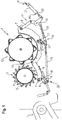
- a feeder to which a threshing drum comprising a plurality of threshing drums 2 of a combine harvester not shown follows.
- the threshing device 2 consists essentially of a first threshing drum 3, the pre-acceleration drum, with a closed cylinder jacket 4, are placed on the distributed driver 5 and a second threshing drum 12, the blow bars distributed on its outer surface 13, in the closed version, distributed over its circumference 15 has.
- a third threshing drum of the threshing device 2 designed as a turning drum or feed drum is not shown.
- the first threshing cylinder 3 is a first concave 6, assigned.
- the second threshing cylinder 12 is associated with a second concave 14.
- first threshing concave 6 and the second concave 14 are positionally adjustable by means of a threshing concealer 23 relative to the respective surface of the first threshing drum 3 and the second threshing drum 12.
- the first and the second concave 6, 14 are provided with pivot axes 7, on which tabs 8 are placed.
- the respective tab 8 is pivotally connected to an angle lever 9, 10 and 11 respectively.
- the respective angle lever 9, 10 and 11 is pivotable about a fixed axis 16, 17 and 18, wherein the lugs 8 facing away from the legs of the angle lever 9, 10 and 11 are connected to each other by a coupling 19 and 20 respectively.
- One leg of the angle lever 11 has an extension 21, to which a Piston rod 22 at least one double-acting hydraulic cylinder 21 attacks.
- At least the angle lever 9, 10, 11, the respective coupling 19, 20 and the at least one double-acting hydraulic cylinder 21 are part of the threshing concealer 23.
- the two concaves 6, 14 are adjusted, whereby their distance from the lateral surface the threshing cylinder 3 and the threshing drum 12 changed.
- the at least one hydraulic cylinder 21 is acted upon by means of a designed as a constant pressure system working hydraulics of the combine harvester with a hydraulic pressure to actuate the Dreschkorbverstellvorraum 23.
- the movement of the concaves 6, 14 in the direction of the respective threshing drums 3, 12 by the retraction of the piston rod 22 is referred to as closing.
- the movement of the concaves 6, 14 in the direction away from the respective threshing drums 3, 12 by the extension of the piston rod 22 is referred to as opening.
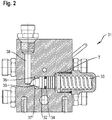
- the representation in Fig. 2 shows a sectional view of a switching valve 31.
- the switching valve 31 is designed as a 2/2-way seat valve and shown in its normal position in which the switching valve 31 blocks.
- the switching valve 31 comprises a slide 32, which is acted upon by a compression spring 33 with a compressive force to hold the switching valve 31 in the illustrated basic position.
- the slider 32 is pressed by the compression spring 33 against the valve seat 35.
- the slide 32 has an annular surface 36 which can be acted upon by a hydraulic pressure and a seal 34. By the seal 34, the slider 32 is leak-free sealed to the tank T.
- the switching valve 31 opens when a first control pressure 37 or a second control pressure 38 are present.
- Fig. 3 is a circuit diagram of a portion of a hydraulic circuit 40 of the working hydraulics of the combine for threshing concave 23 is shown.
- the working hydraulic system designed as a constant-pressure system provides a constant hydraulic pressure P by means of a hydraulic pump, which is driven by an internal combustion engine of the combine harvester, and at least one accumulator among other things for controlling and operating the concave adjustment 23 is used.
- the hydraulic circuit 40 comprises an electrically operated 3/2-way valve 41 and a 2/2-way valve 43 which is connected by a hydraulic line 42, and the switching valve 31, which fluidly through a hydraulic line 47 with the ring side of the hydraulic cylinder 21 connected is.
- the at least one hydraulic cylinder 21 of the concave adjustment device 23 can be acted on the piston side with the hydraulic pressure P.
- the 2/2-way valve 43 is fluidly connected by a supply line 44 with the piston side of the double-acting hydraulic cylinder 21.
- the switching valve 21, which serves for switching off the internal combustion engine and the associated collapse of the hydraulic pressure P of the constant pressure system, is fluid-conductively connected by a supply line 45 to the hydraulic cylinder 21.
- the representation in Fig. 3 shows the 3/2-way valves 41, the 2/2-way valve 43 and the switching valve 31 each in a basic position, which they occupy by being acted upon by a compression spring.
- the 3/2-way valve 41 is connected by its one connection with a leading to a tank T hydraulic line TL and by its other connection to a hydraulic line PL, in which the hydraulic pressure P prevails.
- the hydraulic line 42 is connected to the tank line TL.
- the switching valve 31 locks in its basic position shown the flow of hydraulic oil from or to the ring side of the hydraulic cylinder 21.
- the 2/2-way valve 43 locks in its basic position shown the flow of hydraulic oil from or to the piston side of the hydraulic cylinder 21st
- the hydraulic pump 41 of the constant pressure system provides the hydraulic oil with constant hydraulic pressure P.
- This hydraulic pressure P forms the first control pressure 37, which is present at a first control port 45 of the switching valve 31, whereby it is transferred to an open position.
- the supply line 47 and the hydraulic line PL are connected to each other.
- a hydraulic pressure P2 is a hydraulic pressure P2 as the second control pressure 38, which prevails on the ring side of the hydraulic cylinder 21.
- the switching valve 31 opens regardless of which of the two control terminals 45 or 46 is driven. That is, the control valve 31 opens in both flow directions regardless of which of the hydraulic pressures P2 or P is higher due to operation.
- the switching valve 31 allows, depending on the dimensions of the compression spring 33, the valve seat 35 and the annular surface 36 different opening pressures.
- the hydraulic pressure P is applied to the piston side on the piston side in order to increase the distance between the lateral surface of the threshing drums 3, 12 and the concaves 6, 14.
- the 3/2-way valve 41 and this subordinate 2/2-Wegeventiel 43 are electrically controlled, so that the connection between the hydraulic lines 42, 44 and the pressure line PL is made.
- the piston ring side hydraulic oil is displaced accordingly and flows through the open switching valve 31 into a memory of the constant pressure system.
- the 3/2-way valve 41 and the 2/2-way valve 43 by adjusting the distance between the lateral surface of the threshing drums 3, 12 and the concaves 6, 14 by controlling transferred to their basic position via their respective tax connection.
- the switching valve 31 is still in the open position due to at least one pending control pressure 37 or 38. If an overload situation occurs on a concave 6, 14, the piston rod 22 is temporarily extended in order to increase the distance between the concave 6, 14 and the lateral surface of the threshing cylinder 5, 12.
- the ring-side hydraulic pressure P2 acts as a spring. At the same time, a vacuum occurs on the piston side, which causes the piston rod 22 to retract after overcoming the overload situation, so that the concaves 6, 14 again assume their positions set by means of the concave adjustment device 23.
- the hydraulic pressure P is applied to the at least one hydraulic cylinder 21 by the switching valve 31 on the piston ring side. Due to the upcoming control pressure 37, 38 on the switching valve 31 remains open.
- the 3/2-way valves 41 and the 2/2-way valve 43 are driven to close the concaves 6, 14 in such a way that they open, so that the hydraulic oil can be displaced piston side.
- Switching off the combine harvester causes the working hydraulics designed as a constant pressure system to provide no hydraulic pressure P.
- the 3/2-way valves 41 and the 2/2-way valve 43 are transferred to their normal position.
- the elimination of the control pressures 37, 38 on the switching valve 31 causes the switching valve 31 is automatically transferred by the compression spring 33 in its normal position in which the switching valve 31 blocks.
- a ring-side minimum pressure in the hydraulic cylinder 21 is maintained thereby, since a drainage of the hydraulic oil is prevented by the blocking of the switching valve 31.
- the concaves 6, 14 are held in a last position set by the 3/2-way valve, whereby a check or mechanical adjustment of the concealment device 23 in the maintenance case is readily possible.
- a use of the at least one hydraulic cylinder 21 in the reverse arrangement of piston and ring side is of course also possible.
Landscapes
- Life Sciences & Earth Sciences (AREA)
- Environmental Sciences (AREA)
- Threshing Machine Elements (AREA)
- Fluid-Driven Valves (AREA)
Abstract
- die Dreschkorbverstellvorrichtung (23) mittels zumindest eines doppeltwirkenden Hydraulikzylinders (21) betätigbar ist, und
- der zumindest eine Hydraulikzylinder (21) zur Einstellung eines Abstands des Dreschkorbes (6) zu der Mantelfläche (4) der Dreschtrommel (3, 12) kolbenseitig sowie ringseitig mit einem Hydraulikdruck (P, P2) beaufschlagbar ist, wobei durch die Abschaltung der Arbeitshydraulik (41) ein Schaltventil (31) ansteuerbar ist, so dass ein Mindestdruck (P2) bestehen bleibt, um den zumindest einen Hydraulikzylinder (21) in seiner zuletzt eingestellten Position zu halten.
Description
- Die vorliegende Erfindung betrifft einen Mähdrescher mit einer Dreschvorrichtung, umfassend zumindest eine Dreschtrommel sowie zumindest einen die Dreschtrommel abschnittsweise umgebenden Dreschkorb, der zur Mantelfläche der zumindest einen Dreschtrommel mittels einer Dreschkorbverstellvorrichtung abstandsveränderlich positionierbar ist, sowie mit einer Arbeitshydraulik zum Betreiben zumindest der Dreschvorrichtung, wobei die Dreschkorbverstellvorrichtung mittels zumindest eines doppeltwirkenden Hydraulikzylinders betätigbar ist, und der zumindest eine Hydraulikzylinder zur Einstellung eines Abstands des Dreschkorbes zur Dreschtrommel kolbenseitig und ringseitig mit einem Hydraulikdruck beaufschlagbar ist.
- Aus der
DE 70 16 014 U1 ist ein Mähdrescher mit einer Dreschvorrichtung der eingangs genannten Art bekannt. Die Dreschvorrichtung weist eine Dreschtrommel und einen diese abschnittsweise umgebenden Dreschkorb auf. Der Dreschkorb ist mittels einer Hebelanordnung, die von einer Kolbenstange eines doppeltwirkenden Hydraulikzylinders betätigt wird, zur Dreschtrommel abstandsveränderlich positionierbar. Der Hydraulikzylinder wird durch ein 3/2-Wegeventil gesteuert, welches eine Zuführstellung, eine neutrale Stellung und eine Entleerungsstellung einnehmen kann. In der Zuführstellung wird dem Hydraulikzylinder ein hydraulisches Druckmittel von einer Hydraulikpumpe zum Ausfahren der Kolbenstange zugeführt. In der neutralen Stellung werden das Zuführen zum Stößel sowie das Abführen des hydraulischen Druckmittels vom Stößel unterbunden, sodass der Dreschkorb seinen Abstand zur Dreschtrommel nicht verändert. Die Hydraulikpumpe wird mittels eines Antriebsaggregates des Mähdreschers angetrieben. In der Entleerungsstellung ist der Hydraulikzylinder mit einem Tank verbunden, um die Kolbenstange einzufahren. Die Betätigung des 3/2-Wegeventils erfolgt manuell durch eine Bedienperson. Hierzu umfasst das 3/2-Wegeventil eine Betätigungsstange, die durch einen Gelenkbolzen mit einem schwimmend gelagerten Hebel verbunden ist, dessen eines Ende durch einen Bolzen gelenkig mit einem Hebel der Hebelanordnung verbunden ist, und dessen anderes Ende durch einen Bowdenzug mit einem Betätigungshebel in einer Kabine des Mähdreschers verbunden ist. Mit dem Abschalten des Antriebsaggregates des Mähdreschers wird auch die Hydraulikpumpe abgeschaltet, so dass kein hydraulisches Druckmittel gefördert wird. Um den Dreschkorb in einer definierten Position zu halten, ist erforderlich, vor dem Abschalten des Mähdreschers der Betätigungshebel in eine Schaltstellung zu überführen, in der das 3/2-Wegeventil eine neutrale Stellung einnimmt. - Vor diesem Hintergrund ist es die Aufgabe der vorliegenden Erfindung, einen Mähdrescher der eingangs genannten Art derart weiterzubilden, dass der Dreschkorb bei Abschaltung eines Antriebsaggregates des Mähdreschers, und mit diesem seiner Arbeitshydraulik, automatisch in seiner zuletzt eingenommenen Position gehalten wird.
- Diese Aufgabe wird erfahrungsgemäß durch die Merkmale des Anspruchs 1 gelöst.
- Vorteilhafte Weiterbildungen sind Gegenstand der Unteransprüche.
- Gemäß dem Anspruch 1 wird ein Mähdrescher mit einer Dreschvorrichtung vorgeschlagen, umfassend zumindest eine Dreschtrommel sowie einen diese abschnittsweise umgebenden Dreschkorb, der zur Mantelfläche der Dreschtrommel mittels einer Dreschkorbverstellvorrichtung abstandsveränderlich positionierbar ist, sowie mit einer Arbeitshydraulik zum Betreiben zumindest der Dreschvorrichtung, hierzu ist die Dreschkorbverstellvorrichtung mittels zumindest eines doppeltwirkenden Hydraulikzylinders betätigbar, indem der zumindest eine Hydraulikzylinder zur Einstellung eines Abstands des Dreschkorbes zu der Mantelfläche der Dreschtrommel kolbenseitig sowie ringseitig mit einem Hydraulikdruck beaufschlagbar ist. Üblicherweise wird der zumindest eine Hydraulikzylinder kolbenseitig mit Druck beaufschlagt, um den Abstand des Dreschkorbes zur Mantelfläche der Dreschtrommel einzustellen und aufrechtzuerhalten. Die Einstellung des Abstands des Dreschkorbes kann manuell oder automatisch erfolgen. Um den Dreschkorb bei Abschaltung eines Antriebsaggregates respektive der von diesem angetriebenen Arbeitshydraulik des Mähdreschers automatisch in seiner zuletzt eingenommenen Position zu halten, ist vorgesehen, dass durch die Abschaltung der Arbeitshydraulik ein Schaltventil ansteuerbar ist, so dass ein Mindestdruck bestehen bleibt, um den Hydraulikzylinder in seiner zuletzt eingestellten Position zu halten. Die Ansteuerung des Schaltventils bewirkt also die Aufrechterhaltung eines, insbesondere ringseitigen, Mindestdrucks, der größer ist als die Gewichtskraft des Dreschkorbes und darin befindlicher Komponenten. Auf diese Weise wird der Hydraulikzylinder in seiner zuletzt eingestellten Position gehalten, da der aufrechterhaltene Mindestdruck der Gewichtskraft des Dreschkorbes entgegenwirkt. Durch die Abschaltung der Arbeitshydraulik, insbesondere einer der Versorgung dienenden Hydraulikpumpe, wird das Schaltventil automatisch in eine Schaltstellung überführt, in der ein Abfließen des Druckmittels aus dem Hydraulikzylinder auf der Seite, je nach Einbausituation der Kolben- oder Ringseite, verhindert wird, zu welcher ein Öffnen des Dreschkorbes erfolgt. Hierdurch wird ein Absacken, im Sinne einer Abstandsvergrößerung zur Mantelfläche der Dreschtrommel, des Dreschkorbes verhindert. Der Dreschkorb wird in seiner aktuellen Position gehalten. Dies ermöglicht auf einfache und kostengünstige Weise eine Überprüfung oder mechanische Justierung der Korbverstellung im Wartungsfall. Insbesondere bedarf es keiner zusätzlichen Hilfsmittel, um den Dreschkorb in seiner letzten Position zu halten.
- Dabei ist es vorteilhaft, dass die Arbeitshydraulik als Konstantdrucksystem ausgebildet ist. Das Konstantdrucksystem verfügt über eine Hydraulikpumpe, die den Arbeitsdruck im Konstantdrucksystem bereitstellt und aufrechterhält. Die Hydraulikpumpe wird von dem Antriebsaggregat angetrieben. Hierzu kann die Hydraulikpumpe als Axialkolbenmaschine ausgeführt sein. Mit der Abschaltung des Antriebsaggregates kommt es aufgrund der Abschaltung der Hydraulikpumpe zu einem sofortigen Druckabfall in dem Konstantdrucksystem. Dieser Druckabfall führt dazu, dass das Schaltventil seine Schaltstellung von offen in geschlossen ändert. Dadurch wird das Abfließen des Druckmittels aus dem Hydraulikzylinder unterbunden. Die Dreschkorbverstellvorrichtung wird in ihrer letzten Position lagefixiert, das heißt der Dreschkorb behält seine zuletzt eingenommene Arbeitsposition bei. Es bedarf dabei keiner zusätzlichen Energieversorgung, um das Schaltventil in seine Sperrstellung zu überführen.
- Insbesondere kann das Schaltventil als 2/2-Wege-Sitzventil ausgebildet sein. Dabei kann das Schaltventil in der Weise ausgebildet sein, dass es in zwei Flussrichtungen öffnen kann, d. h. sowohl bei Beaufschlagung der Kolbenseite mit einem ersten Hydraulikdruck als auch der Ringseite des Hydraulikzylinders mit einem zweiten Hydraulikdruck. Dadurch ist gewährleistet, dass je nach Bewegungsrichtung des Dreschkorbes das Schaltventil in seiner geöffneten Position gehalten wird, sofern ein Hydraulikdruck des Konstantdrucksystems anliegt. Dies ist vor allem dann von Bedeutung, wenn es zwischen der Dreschtrommel und dem Dreschkorb durch einen Erntegutstau zu einer Überlastung kommt. Hierdurch wird auf den Dreschkorb eine Kraft ausgeübt, welche durch die Dreschkorbverstellvorrichtung auf den zumindest einen Hydraulikzylinder übertragen wird. Der dabei auftretende Druck kann den Arbeitsdruck des Konstantdrucksystems überschreiten.
- Bevorzugt kann das Schaltventil einen ersten Steueranschluss und einen zweiten Steueranschluss aufweisen, durch die das Schaltventil ansteuerbar ist, um es in eine Schaltstellung zu überführen, in der das Schaltventil öffnet, unabhängig davon, welcher der beiden Steueranschluss angesteuert wird.
- Insbesondere kann das Schaltventil hydraulisch ansteuerbar sein. Dies hat gegenüber einem elektrisch angesteuerten Schaltventil den Vorteil, dass es kostengünstiger ist und eine geringere Komplexität aufweist.
- Gemäß einer vorteilhaften Weiterbildung ist vorgesehen, dass das Schaltventil einen mit einer Federkraft beaufschlagten Schieber aufweist, welcher leckölfrei abgedichtet ist.
- Insbesondere können in Abhängigkeit von der Federkraft sowie der Ausgestaltung von Ventilsitz und Ringfläche unterschiedliche Öffnungsdrücke einstellbar sein. Dadurch lässt sich ein Steuerdruck einstellen, der an einem der beiden Steueranschlüsse vorliegen muss, um das Schaltventil in seine geöffnete Schaltstellung zu überführen und zu halten.
- Weiterhin kann der zumindest eine Hydraulikzylinder zur Einstellung und zum Halten der eingestellten Position der Dreschkorbverstellvorrichtung durch Ansteuerung eines 3/2-Wegeventils und eines 2/2-Wegeventils verstellbar sein. Dabei erfolgt zum Ausfahren des Hydraulikzylinders eine Betätigung sowohl des 3/2-Wegeventils als auch des 2/2-Wegeventils, während zum Einfahren oder Halten lediglich das 2/2-Wegeventil betätigt wird.
- Vorteilhaft ist es, dass das Schaltventil bei an einem der Steueranschlüsse anstehendem Hydraulikdruck eine Überlastabsicherung freigibt. Die Überlastabsicherung wird durch das sich in geöffneter Schaltstellung befindliche Schaltventil dargestellt. Das Ansteigen des kolbenseitigen Drucks infolge einer Überlastung im Dreschkorb bewirkt auf der Ringseite ein Einfedern der Kolbenstange, so dass der zumindest eine Hydraulikzylinder temporär den Dreschkorb öffnet. Auf der Kolbenseite wird, da sich das 3/2-Wegeventil und das 2/2-Wegeventil zum Halten der Position der Dreschkorbverstellvorrichtung in gesperrter Stellung befinden, temporär ein Vakuum erzeugt, welches nach dem Überwinden der Überlast zu einer Rückführung der Kolbenstange in ihre eingestellte Position führt.
- Die vorliegende Erfindung wird nachstehend anhand eines in den Zeichnungen dargestellten Ausführungsbeispieles näher erläutert.
- Es zeigen:
- Fig. 1
- eine schematische Darstellung eines Dreschwerks mit verstellbarem Dreschkorb eines Mähdreschers in Seitenansicht;
- Fig. 2
- eine Schnittansicht eines Schaltventils;
- Fig. 3
- einen Schaltplan eines Teilabschnitts eines Hydraulikkreises für eine Dreschkorbverstellung.
- In der
Figur 1 ist mit 1 ein Schrägförderer bezeichnet, an den sich eine mehrere Dreschtrommeln umfassende Dreschvorrichtung 2 eines nicht näher dargestellten Mähdreschers anschließt. Die Dreschvorrichtung 2 besteht im Wesentlichen aus einer ersten Dreschtrommel 3, der Vorbeschleunigungstrommel, mit einem geschlossenen Zylindermantel 4, auf den verteilt Mitnehmer 5 aufgesetzt sind sowie einer zweiten Dreschtrommel 12, die auf ihrer Mantelfläche 13, bei geschlossener Ausführung, über ihren Umfang verteilt angeordnete Schlagleisten 15 aufweist. Eine dritte, als Wendetrommel bzw. Zuführtrommel ausgeführte Dreschtrommel der Dreschvorrichtung 2 ist nicht dargestellt. Der ersten Dreschtrommel 3 ist ein erster Dreschkorb 6, zugeordnet. Der zweiten Dreschtrommel 12 ist ein zweiter Dreschkorb 14 zugeordnet. Im Übergangsbereich zwischen der ersten Dreschtrommel 3 und der zweiten Dreschtrommel 12 ist eine so genannte Entgrannereinrichtung angeordnet, die bei Bedarf in den Erntegutfluss einschwenkbar ist, um eine aggressivere Dreschwirkung zu erzielen. Der erste Dreschkorb 6 und der zweite Dreschkorb 14 sind durch eine Dreschkorbverstellvorrichtung 23 gegenüber der jeweiligen Mantelfläche der ersten Dreschtrommel 3 und der zweiten Dreschtrommel 12 abstandsveränderlich positionierbar. Der erste und der zweite Dreschkorb 6, 14 sind mit Schwenkachsen 7 versehen, auf welche Laschen 8 aufgesetzt sind. Die jeweilige Lasche 8 ist gelenkig mit einem Winkelhebel 9, 10 bzw. 11 verbunden. Der jeweilige Winkelhebel 9, 10 und 11 ist um eine feste Achsen 16, 17 bzw. 18 schwenkbar, wobei die den Laschen 8 abgewandten Schenkel der Winkelhebel 9, 10 und 11 miteinander durch eine Koppel 19 bzw. 20 verbunden sind. Ein Schenkel des Winkelhebels 11 weist eine Verlängerung 21 auf, an die eine Kolbenstange 22 zumindest eines doppeltwirkenden Hydraulikzylinders 21 angreift. Zumindest die Winkelhebel 9, 10, 11, die jeweilige Koppel 19, 20 sowie der zumindest eine doppeltwirkende Hydraulikzylinder 21 sind Teil der Dreschkorbverstellvorrichtung 23. Durch Betätigung des zumindest einen Hydraulikzylinders 21 werden die beiden Dreschkörbe 6, 14 verstellt, wodurch sich ihr Abstand zur Mantelfläche der Dreschtrommel 3 bzw. der Dreschtrommel 12 verändert. Der zumindest eine Hydraulikzylinder 21 wird mittels einer als Konstantdrucksystem ausgebildeten Arbeitshydraulik des Mähdreschers mit einem Hydraulikdruck beaufschlagt, um die Dreschkorbverstellvorrichtung 23 zu betätigen. Das Bewegen der Dreschkörbe 6, 14 in Richtung der jeweiligen Dreschtrommeln 3, 12 durch das Einfahren der Kolbenstange 22 wird als Schließen bezeichnet. Hingegen wird das Bewegen der Dreschkörbe 6, 14 in von der jeweiligen Dreschtrommeln 3, 12 abgewandter Richtung durch das Ausfahren der Kolbenstange 22 als Öffnen bezeichnet. - Die Darstellung in
Fig. 2 zeigt eine Schnittansicht eines Schaltventils 31. Das Schaltventil 31 ist als ein 2/2-Wegesitzventil ausgeführt und in seiner Grundstellung dargestellt, in welcher das Schaltventil 31 sperrt. Das Schaltventil 31 umfasst einen Schieber 32, der von einer Druckfeder 33 mit einer Druckkraft beaufschlagt wird, um das Schaltventil 31 in der dargestellten Grundstellung zu halten. Der Schieber 32 wird dazu von der Druckfeder 33 gegen den Ventilsitz 35 gepresst. Der Schieber 32 weist eine mit einem hydraulischen Druck beaufschlagbare Ringfläche 36 sowie eine Dichtung 34 auf. Durch die Dichtung 34 ist der Schieber 32 leckölfrei zum Tank T abgedichtet. Das Schaltventil 31 öffnet, wenn ein erster Steuerdruck 37 oder ein zweiter Steuerdruck 38 anliegen. - In
Fig. 3 ist ein Schaltplan eines Teilabschnitts eines Hydraulikkreises 40 der Arbeitshydraulik des Mähdreschers für die Dreschkorbverstellung 23 dargestellt. Die als Konstantdrucksystem ausgebildete Arbeitshydraulik stellt mittels einer Hydraulikpumpe, die von einem Verbrennungsmotor des Mähdreschers angetrieben wird, und zumindest eines Speichers einen konstanten Hydraulikdruck P bereit, welcher unter anderem zur Ansteuerung und Betätigung der Dreschkorbverstellung 23 verwendet wird. Der Hydraulikkreis 40 umfasst ein elektrisch betätigtes 3/2-Wegeventil 41 und ein diesem nachgeordnetes 2/2-Wegeventil 43, welche durch eine Hydraulikleitung 42 miteinander verbunden sind, sowie das Schaltventil 31, welches durch eine Hydraulikleitung 47 mit der Ringseite des Hydraulikzylinders 21 fluidleitend verbunden ist. - Mittels des 3/2-Wegeventils 41 und des 2/2-Wegeventils 43 ist der zumindest eine Hydraulikzylinder 21 der Dreschkorbverstellvorrichtung 23 kolbenseitig mit dem Hydraulikdruck P beaufschlagbar. Hierzu ist das 2/2-Wegeventils 43 durch eine Zuleitung 44 mit der Kolbenseite des doppeltwirkenden Hydraulikzylinders 21 fluidleitend verbunden. Das Schaltventil 21, welches bei Abschaltung des Verbrennungsmotors und dem damit verbundenen Einbruch des Hydraulikdrucks P des Konstantdrucksystems, dient, ist durch eine Zuleitung 45 mit dem Hydraulikzylinder 21 fluidleitend verbunden. Die Darstellung in
Fig. 3 zeigt das 3/2-Wegeventile 41, das 2/2-Wegeventil 43 sowie das Schaltventil 31 jeweils in einer Grundstellung, welche diese durch eine Beaufschlagung durch eine Druckfeder einnehmen. - Das 3/2-Wegeventil 41 ist durch seinen einen Anschluss mit einer zu einem Tank T führenden Hydraulikleitung TL sowie durch seinen anderen Anschluss mit einer Hydraulikleitung PL verbunden, in welcher der Hydraulikdruck P herrscht. In der dargestellten Grundstellung des 3/2-Wegeventils 41 ist die Hydraulikleitung 42 mit der Tankleitung TL verbunden. Das Schaltventil 31 sperrt in seiner gezeigten Grundstellung den Fluss von Hydrauliköl von oder zu der Ringseite des Hydraulikzylinders 21. Das 2/2-Wegeventil 43 sperrt in seiner gezeigten Grundstellung den Fluss von Hydrauliköl von oder zu der Kolbenseite des Hydraulikzylinders 21.
- Im laufenden Betrieb des Mähdreschers stellt die Hydraulikpumpe 41 des Konstantdrucksystems das Hydrauliköl mit konstantem Hydraulikdruck P bereit. Dieser Hydraulikdruck P bildet den ersten Steuerdruck 37, der an einem ersten Steueranschluss 45 des Schaltventils 31 ansteht, wodurch dieses in eine geöffnete Stellung überführt wird. In geöffneter Stellung des Schaltventils 31 sind die Zuleitung 47 und die Hydraulikleitung PL miteinander verbunden sind. An einem zweiten Steueranschluss 46 steht ein Hydraulikdruck P2 als zweiter Steuerdruck 38 an, welcher auf der Ringseite des Hydraulikzylinders 21 herrscht. Das Schaltventil 31 öffnet unabhängig davon, welcher der beiden Steueranschlüsse 45 oder 46 angesteuert wird. Das heißt, dass das Steuerventil 31 in beiden Flussrichtungen öffnet, unabhängig davon welcher der Hydraulikdrücke P2 oder P betriebsbedingt höher ist. Das Schaltventil 31 lässt in Anhängigkeit von der Dimensionierung der Druckfeder 33, des Ventilsitzes 35 und der Ringfläche 36 unterschiedliche Öffnungsdrücke zu.
- Für das Öffnen des oder der Dreschkörbe 6, 14 wird der zumindest eine Hydraulikzylinder 21 kolbenseitig mit dem Hydraulikdruck P beaufschlagt, um den Abstand zwischen der Mantelfläche der Dreschtrommeln 3, 12 und den Dreschkörben 6, 14 zu vergrößern. Hierzu werden das 3/2-Wegeventil 41 und das diesem nachgeordnete 2/2-Wegeventiel 43 elektrisch angesteuert, so dass die Verbindung zwischen den Hydraulikleitungen 42, 44 und der Druckleitung PL hergestellt ist. Das kolbenringseitige Hydrauliköl wird entsprechend verdrängt und fließt über das geöffnete Schaltventil 31 in einen Speicher des Konstantdrucksystems ab.
- Zum Halten der Dreschkörbe 6, 14 während des laufenden Betriebs des Mähdreschers werden das 3/2-Wegeventil 41 und das 2/2-Wegeventil 43 nach erfolgter Einstellung des Abstandes zwischen der Mantelfläche der Dreschtrommeln 3, 12 und den Dreschkörben 6, 14 durch Ansteuerung über ihren jeweiligen Steueranschluss in ihre Grundstellung überführt. Das Schaltventil 31 ist aufgrund zumindest eines anstehenden Steuerdruckes 37 oder 38 weiterhin in geöffneter Stellung. Tritt eine Überlastsituation an einem Dreschkorb 6, 14 auf, so wird die Kolbenstange 22 temporär ausgefahren, um den Abstand zwischen Dreschkorb 6, 14 und der Mantelfläche der Dreschtrommel 5, 12 zu vergrößern. Der ringseitige Hydraulikdruck P2 wirkt dabei als Feder. Auf der Kolbenseite tritt zugleich ein Vakuum auf, welches nach dem Überwinden der Überlastsituation ein Einziehen der Kolbenstange 22 bewirkt, so dass die Dreschkörbe 6, 14 wieder ihre mittels der Dreschkorbverstellvorrichtung 23 eingestellten Positionen einnehmen.
- Zum Schließen der Dreschkörbe 6, 14 wird der zumindest eine Hydraulikzylinder 21 kolbenringseitig mit dem Hydraulikdruck P durch das Schaltventil 31 beaufschlagt. Aufgrund des anstehenden Steuerdrucks 37, 38 an dem Schaltventil 31 bleibt dieses geöffnet. Das 3/2-Wegeventile 41 und das 2/2-Wegeventil 43 werden zum Schließen der Dreschkörbe 6, 14 in der Weise angesteuert, dass diese Öffnen, so dass das Hydrauliköl kolbenseitig verdrängt werden kann.
- Das Abschalten des Mähdreschers führt dazu, dass die als Konstantdrucksystem ausgeführte Arbeitshydraulik keinen Hydraulikdruck P bereitstellt. Das 3/2-Wegeventile 41 und das 2/2-Wegeventil 43 werden in ihre Grundstellung überführt. Der Fortfall der Steuerdrücke 37, 38 an dem Schaltventil 31 führt dazu, dass das Schaltventil 31 durch die Druckfeder 33 automatisch in seine Grundstellung überführt wird, in welcher das Schaltventil 31 sperrt. Ein ringseitiger Mindestdruck im Hydraulikzylinder 21 bleibt dadurch aufrechterhalten, da ein Abfließen des Hydrauliköls durch das Sperren des Schaltventils 31 verhindert wird. Dadurch wird auf einfache Weise vermieden, dass die Dreschkörbe 6, 14 aufgrund ihres Eigegenwichts und des fehlenden Arbeitsdruckes zum Betreiben der Dreschkorbverstellvorrichtung 23 absinken können. Somit werden die Dreschkörbe 6, 14 in einer zuletzt durch das 3/2-Wegeventil eingestellten Position gehalten, wodurch eine Überprüfung oder mechanische Justierung der Dreschkorbverstellvorrichtung 23 im Wartungsfall ohne weiteres möglich ist.
- Eine Verwendung des zumindest einen Hydraulikzylinders 21 bei umgekehrter Anordnung von Kolben- und Ringseite ist selbstverständlich auch möglich.
Bezugszeichenliste 1 Schrägförderer 37 Erster Steuerdruck 2 Dreschvorrichtung 38 Zweiter Steuerdruck 3 Dreschtrommel 4 Zylindermantel 40 Hydraulikkreis 5 Mitnehmer 41 3/2-Wegeventil 6 Dreschkorb 42 Hydraulikleitung 7 Schwenkachse 43 2/2-Wegeventil 8 Lasche 44 Hydraulikleitung 9 Winkelhebel 45 Erster Steueranschluss 10 Winkelhebel 46 Zweiter Steueranschluss 11 Winkelhebel 47 Hydraulikleitung 12 Dreschtrommel 13 Mantelfläche P Hydraulikdruck 14 Dreschkorb P2 Hydraulikdruck 15 Schlagleiste PL Druckleitung 16 Achse TL Tankleitung 17 Achse 18 Achse 19 Koppel 20 Koppel 21 Hydraulikzylinder 22 Kolbenstange 23 Dreschkorbverstellvorrichtung 31 Schaltventil 32 Schieber 33 Druckfeder 34 Dichtung 35 Ventilsitz 36 Ringfläche
Claims (10)
- Mähdrescher mit einer Dreschvorrichtung (2), umfassend zumindest eine Dreschtrommel (3, 12) sowie einen diese abschnittsweise umgebenden Dreschkorb (6, 14), der zur Mantelfläche (4, 13) der Dreschtrommel (3, 12) mittels einer hydraulisch betätigbaren Dreschkorbverstellvorrichtung (23) abstandsveränderlich positionierbar ist, sowie mit einer Arbeitshydraulik zum Betreiben Dreschvorrichtung (2), wobei- die Dreschkorbverstellvorrichtung (23) mittels zumindest eines doppeltwirkenden Hydraulikzylinders (21) betätigbar ist, und- der zumindest eine Hydraulikzylinder (21) zur Einstellung eines Abstands des Dreschkorbes (6, 14) zu der Mantelfläche (4, 13) der Dreschtrommel (3, 12) kolbenseitig sowie ringseitig mit einem Hydraulikdruck (P, P2) beaufschlagbar ist,dadurch gekennzeichnet, dass durch die Abschaltung der Arbeitshydraulik (41) ein Schaltventil (31) ansteuerbar ist, so dass ein r Mindestdruck (P2) bestehen bleibt, um den zumindest einen Hydraulikzylinder (21) in seiner zuletzt eingestellten Position zu halten.
- Mähdrescher nach Anspruch 1, dadurch gekennzeichnet, dass die Arbeitshydraulik (41) als Konstantdrucksystem ausgebildet ist.
- Mähdrescher nach Anspruch 1 oder 2, dadurch gekennzeichnet, dass das Schaltventil (31) als 2/2-Wege-Sitzventil ausgebildet ist.
- Mähdrescher nach einem der Ansprüche 1 bis 3, dadurch gekennzeichnet, dass das Schaltventil (31) einen ersten Steueranschluss (45) und einen zweiten Steueranschluss (46) aufweist, durch die das Schaltventil (31) ansteuerbar ist, um zu öffnen, unabhängig davon, welcher Steueranschluss (45, 46) angesteuert wird.
- Mähdrescher nach einem der Ansprüche 4 oder 5, dadurch gekennzeichnet, dass das Schaltventil (31) hydraulisch ansteuerbar ist.
- Mähdrescher nach einem der vorangehenden Ansprüche, dadurch gekennzeichnet, dass das Schaltventil (31) einen mit einer Federkraft beaufschlagten Schieber (32) aufweist, welcher leckölfrei abgedichtet ist.
- Mähdrescher nach Anspruch 6, dadurch gekennzeichnet, dass in Abhängigkeit von der Federkraft sowie der Ausgestaltung von Ventilsitz (36) und Ringfläche (36) unterschiedliche Öffnungsdrücke einstellbar sind.
- Mähdrescher nach einem der vorangehenden Ansprüche, dadurch gekennzeichnet, dass der zumindest eine Hydraulikzylinder (21) zur Einstellung und zum Halten der eingestellten Position der Dreschkorbverstellvorrichtung (23) durch Ansteuerung eines 3/2-Wegeventil (41) und eines 2/2-Wegeventils (43) verstellbar ist.
- Mähdrescher nach einem der vorangehenden Ansprüche, dadurch gekennzeichnet, dass das Schaltventil (31) bei anstehendem Hydraulikdruck (P) eine Überlastabsicherung freigibt.
- Mähdrescher nach einem der vorangehenden Ansprüche, dadurch gekennzeichnet, dass der zumindest eine Hydraulikzylinder (21) kolbenseitig mit einem von einer Hydraulikpumpe (41) der Arbeitshydraulik bereitgestellten Hydraulikdruck (P) beaufschlagbar ist.
Applications Claiming Priority (1)
| Application Number | Priority Date | Filing Date | Title |
|---|---|---|---|
| DE102017118759.6A DE102017118759A1 (de) | 2017-08-17 | 2017-08-17 | Mähdrescher mit einer Dreschvorrichtung |
Publications (2)
| Publication Number | Publication Date |
|---|---|
| EP3443834A1 true EP3443834A1 (de) | 2019-02-20 |
| EP3443834B1 EP3443834B1 (de) | 2020-08-05 |
Family
ID=62025673
Family Applications (1)
| Application Number | Title | Priority Date | Filing Date |
|---|---|---|---|
| EP18167893.9A Active EP3443834B1 (de) | 2017-08-17 | 2018-04-18 | Mähdrescher mit einer dreschvorrichtung |
Country Status (2)
| Country | Link |
|---|---|
| EP (1) | EP3443834B1 (de) |
| DE (1) | DE102017118759A1 (de) |
Cited By (2)
| Publication number | Priority date | Publication date | Assignee | Title |
|---|---|---|---|---|
| CN113519279A (zh) * | 2021-07-22 | 2021-10-22 | 江苏大学 | 液压式变直径脱粒滚筒的液压自适应驱控系统及自适应控制方法 |
| CN115517071A (zh) * | 2022-09-30 | 2022-12-27 | 潍柴雷沃智慧农业科技股份有限公司 | 收割机滚筒凹板间隙浮动液压控制系统及方法和滚筒组件 |
Citations (4)
| Publication number | Priority date | Publication date | Assignee | Title |
|---|---|---|---|---|
| DE7016014U (de) | 1970-04-28 | 1971-01-14 | Massey Ferguson Inc | Dreschvorrichtung. |
| US4222395A (en) * | 1979-04-30 | 1980-09-16 | Allis-Chalmers Corporation | Threshing cage fingers for retarding the flow of material through an axial flow harvester |
| EP2752108A2 (de) * | 2013-01-04 | 2014-07-09 | CLAAS Selbstfahrende Erntemaschinen GmbH | Dreschvorrichtung |
| EP3023001A1 (de) * | 2014-10-31 | 2016-05-25 | Deere & Company | Selbsteinstellendes konkavspaltsystem |
-
2017
- 2017-08-17 DE DE102017118759.6A patent/DE102017118759A1/de not_active Withdrawn
-
2018
- 2018-04-18 EP EP18167893.9A patent/EP3443834B1/de active Active
Patent Citations (4)
| Publication number | Priority date | Publication date | Assignee | Title |
|---|---|---|---|---|
| DE7016014U (de) | 1970-04-28 | 1971-01-14 | Massey Ferguson Inc | Dreschvorrichtung. |
| US4222395A (en) * | 1979-04-30 | 1980-09-16 | Allis-Chalmers Corporation | Threshing cage fingers for retarding the flow of material through an axial flow harvester |
| EP2752108A2 (de) * | 2013-01-04 | 2014-07-09 | CLAAS Selbstfahrende Erntemaschinen GmbH | Dreschvorrichtung |
| EP3023001A1 (de) * | 2014-10-31 | 2016-05-25 | Deere & Company | Selbsteinstellendes konkavspaltsystem |
Cited By (2)
| Publication number | Priority date | Publication date | Assignee | Title |
|---|---|---|---|---|
| CN113519279A (zh) * | 2021-07-22 | 2021-10-22 | 江苏大学 | 液压式变直径脱粒滚筒的液压自适应驱控系统及自适应控制方法 |
| CN115517071A (zh) * | 2022-09-30 | 2022-12-27 | 潍柴雷沃智慧农业科技股份有限公司 | 收割机滚筒凹板间隙浮动液压控制系统及方法和滚筒组件 |
Also Published As
| Publication number | Publication date |
|---|---|
| EP3443834B1 (de) | 2020-08-05 |
| DE102017118759A1 (de) | 2019-02-21 |
Similar Documents
| Publication | Publication Date | Title |
|---|---|---|
| EP1915538B1 (de) | Schaltung zur ansteuerung eines doppeltwirkenden hydraulischen antriebszylinders | |
| EP1450048A1 (de) | Ventilanordnung | |
| EP2344700B1 (de) | Vorrichtung zum ausgleich hydraulischer wirkdrücke | |
| DE60032732T2 (de) | Rohrbruch steuerventil vorrichtung | |
| DE2140882C3 (de) | Hydraulische Verstelleinrichtung für höhenverstellbare Arbeitsgeräte, insbesondere landwirtschaftliche Bodenbearbeitungsgeräte | |
| DE102017119859A1 (de) | Steuer- und/oder Regelsystem, landwirtschaftliches Nutzfahrzeug und Verfahren zur Steuerung und/oder Regelung | |
| EP0934804B1 (de) | Druckmittelbetriebene Schlagvorrichtung | |
| EP3677796B1 (de) | Hydraulische betätigungsvorrichtung sowie arbeitsfahrzeug mit einem anbaugerät | |
| EP3443834B1 (de) | Mähdrescher mit einer dreschvorrichtung | |
| DE10356970A1 (de) | Steuervorrichtung für ein hydraulisches Ventil zum Halten einer Last | |
| DE102017207771A1 (de) | Seegangkompensationseinrichtung | |
| AT406072B (de) | Hydraulische betätigungsanordnung | |
| DE10356969A1 (de) | HYdraulikschaltung für ein optionales Werkzeug eines schweren Baugeräts | |
| DE4235762A1 (de) | Hydraulische schaltung | |
| EP3884743B1 (de) | Anbaudrehpflug | |
| EP3443828A1 (de) | Hydraulische druckmittelversorgung und adapterventileinheit | |
| DE60306847T2 (de) | Pflugwendevorrichtung | |
| DE69703170T2 (de) | Hydrauliksystem | |
| DE2727555A1 (de) | Steuervorrichtung fuer hydrostatische verdraengeraggregate | |
| AT502034B1 (de) | Hydraulische steuerung für einen drehpflug | |
| DE7626855U1 (de) | Steuerventil | |
| EP3756435B1 (de) | Vorrichtung zur einstellung eines hydraulischen oberlenkers | |
| EP2639104B1 (de) | Hydrauliksteuerung eines einfach wirkenden Kipperzylinders | |
| DE2450330C3 (de) | Doppelhydraulischer Stellantrieb | |
| DE10016026C2 (de) | Hydraulische Leitungskupplungsanordnung |
Legal Events
| Date | Code | Title | Description |
|---|---|---|---|
| PUAI | Public reference made under article 153(3) epc to a published international application that has entered the european phase |
Free format text: ORIGINAL CODE: 0009012 |
|
| STAA | Information on the status of an ep patent application or granted ep patent |
Free format text: STATUS: THE APPLICATION HAS BEEN PUBLISHED |
|
| AK | Designated contracting states |
Kind code of ref document: A1 Designated state(s): AL AT BE BG CH CY CZ DE DK EE ES FI FR GB GR HR HU IE IS IT LI LT LU LV MC MK MT NL NO PL PT RO RS SE SI SK SM TR |
|
| AX | Request for extension of the european patent |
Extension state: BA ME |
|
| STAA | Information on the status of an ep patent application or granted ep patent |
Free format text: STATUS: REQUEST FOR EXAMINATION WAS MADE |
|
| 17P | Request for examination filed |
Effective date: 20190820 |
|
| RBV | Designated contracting states (corrected) |
Designated state(s): AL AT BE BG CH CY CZ DE DK EE ES FI FR GB GR HR HU IE IS IT LI LT LU LV MC MK MT NL NO PL PT RO RS SE SI SK SM TR |
|
| GRAP | Despatch of communication of intention to grant a patent |
Free format text: ORIGINAL CODE: EPIDOSNIGR1 |
|
| STAA | Information on the status of an ep patent application or granted ep patent |
Free format text: STATUS: GRANT OF PATENT IS INTENDED |
|
| RIC1 | Information provided on ipc code assigned before grant |
Ipc: A01F 12/28 20060101AFI20200327BHEP |
|
| INTG | Intention to grant announced |
Effective date: 20200417 |
|
| GRAS | Grant fee paid |
Free format text: ORIGINAL CODE: EPIDOSNIGR3 |
|
| GRAA | (expected) grant |
Free format text: ORIGINAL CODE: 0009210 |
|
| STAA | Information on the status of an ep patent application or granted ep patent |
Free format text: STATUS: THE PATENT HAS BEEN GRANTED |
|
| AK | Designated contracting states |
Kind code of ref document: B1 Designated state(s): AL AT BE BG CH CY CZ DE DK EE ES FI FR GB GR HR HU IE IS IT LI LT LU LV MC MK MT NL NO PL PT RO RS SE SI SK SM TR |
|
| REG | Reference to a national code |
Ref country code: GB Ref legal event code: FG4D Free format text: NOT ENGLISH |
|
| REG | Reference to a national code |
Ref country code: CH Ref legal event code: EP |
|
| REG | Reference to a national code |
Ref country code: AT Ref legal event code: REF Ref document number: 1297399 Country of ref document: AT Kind code of ref document: T Effective date: 20200815 |
|
| REG | Reference to a national code |
Ref country code: DE Ref legal event code: R096 Ref document number: 502018002063 Country of ref document: DE |
|
| REG | Reference to a national code |
Ref country code: IE Ref legal event code: FG4D Free format text: LANGUAGE OF EP DOCUMENT: GERMAN |
|
| REG | Reference to a national code |
Ref country code: LT Ref legal event code: MG4D |
|
| REG | Reference to a national code |
Ref country code: NL Ref legal event code: MP Effective date: 20200805 |
|
| PG25 | Lapsed in a contracting state [announced via postgrant information from national office to epo] |
Ref country code: FI Free format text: LAPSE BECAUSE OF FAILURE TO SUBMIT A TRANSLATION OF THE DESCRIPTION OR TO PAY THE FEE WITHIN THE PRESCRIBED TIME-LIMIT Effective date: 20200805 Ref country code: SE Free format text: LAPSE BECAUSE OF FAILURE TO SUBMIT A TRANSLATION OF THE DESCRIPTION OR TO PAY THE FEE WITHIN THE PRESCRIBED TIME-LIMIT Effective date: 20200805 Ref country code: BG Free format text: LAPSE BECAUSE OF FAILURE TO SUBMIT A TRANSLATION OF THE DESCRIPTION OR TO PAY THE FEE WITHIN THE PRESCRIBED TIME-LIMIT Effective date: 20201105 Ref country code: HR Free format text: LAPSE BECAUSE OF FAILURE TO SUBMIT A TRANSLATION OF THE DESCRIPTION OR TO PAY THE FEE WITHIN THE PRESCRIBED TIME-LIMIT Effective date: 20200805 Ref country code: NO Free format text: LAPSE BECAUSE OF FAILURE TO SUBMIT A TRANSLATION OF THE DESCRIPTION OR TO PAY THE FEE WITHIN THE PRESCRIBED TIME-LIMIT Effective date: 20201105 Ref country code: LT Free format text: LAPSE BECAUSE OF FAILURE TO SUBMIT A TRANSLATION OF THE DESCRIPTION OR TO PAY THE FEE WITHIN THE PRESCRIBED TIME-LIMIT Effective date: 20200805 Ref country code: ES Free format text: LAPSE BECAUSE OF FAILURE TO SUBMIT A TRANSLATION OF THE DESCRIPTION OR TO PAY THE FEE WITHIN THE PRESCRIBED TIME-LIMIT Effective date: 20200805 Ref country code: GR Free format text: LAPSE BECAUSE OF FAILURE TO SUBMIT A TRANSLATION OF THE DESCRIPTION OR TO PAY THE FEE WITHIN THE PRESCRIBED TIME-LIMIT Effective date: 20201106 Ref country code: PT Free format text: LAPSE BECAUSE OF FAILURE TO SUBMIT A TRANSLATION OF THE DESCRIPTION OR TO PAY THE FEE WITHIN THE PRESCRIBED TIME-LIMIT Effective date: 20201207 |
|
| PG25 | Lapsed in a contracting state [announced via postgrant information from national office to epo] |
Ref country code: RS Free format text: LAPSE BECAUSE OF FAILURE TO SUBMIT A TRANSLATION OF THE DESCRIPTION OR TO PAY THE FEE WITHIN THE PRESCRIBED TIME-LIMIT Effective date: 20200805 Ref country code: LV Free format text: LAPSE BECAUSE OF FAILURE TO SUBMIT A TRANSLATION OF THE DESCRIPTION OR TO PAY THE FEE WITHIN THE PRESCRIBED TIME-LIMIT Effective date: 20200805 Ref country code: PL Free format text: LAPSE BECAUSE OF FAILURE TO SUBMIT A TRANSLATION OF THE DESCRIPTION OR TO PAY THE FEE WITHIN THE PRESCRIBED TIME-LIMIT Effective date: 20200805 Ref country code: NL Free format text: LAPSE BECAUSE OF FAILURE TO SUBMIT A TRANSLATION OF THE DESCRIPTION OR TO PAY THE FEE WITHIN THE PRESCRIBED TIME-LIMIT Effective date: 20200805 Ref country code: IS Free format text: LAPSE BECAUSE OF FAILURE TO SUBMIT A TRANSLATION OF THE DESCRIPTION OR TO PAY THE FEE WITHIN THE PRESCRIBED TIME-LIMIT Effective date: 20201205 |
|
| PG25 | Lapsed in a contracting state [announced via postgrant information from national office to epo] |
Ref country code: EE Free format text: LAPSE BECAUSE OF FAILURE TO SUBMIT A TRANSLATION OF THE DESCRIPTION OR TO PAY THE FEE WITHIN THE PRESCRIBED TIME-LIMIT Effective date: 20200805 Ref country code: CZ Free format text: LAPSE BECAUSE OF FAILURE TO SUBMIT A TRANSLATION OF THE DESCRIPTION OR TO PAY THE FEE WITHIN THE PRESCRIBED TIME-LIMIT Effective date: 20200805 Ref country code: DK Free format text: LAPSE BECAUSE OF FAILURE TO SUBMIT A TRANSLATION OF THE DESCRIPTION OR TO PAY THE FEE WITHIN THE PRESCRIBED TIME-LIMIT Effective date: 20200805 Ref country code: RO Free format text: LAPSE BECAUSE OF FAILURE TO SUBMIT A TRANSLATION OF THE DESCRIPTION OR TO PAY THE FEE WITHIN THE PRESCRIBED TIME-LIMIT Effective date: 20200805 Ref country code: SM Free format text: LAPSE BECAUSE OF FAILURE TO SUBMIT A TRANSLATION OF THE DESCRIPTION OR TO PAY THE FEE WITHIN THE PRESCRIBED TIME-LIMIT Effective date: 20200805 |
|
| REG | Reference to a national code |
Ref country code: DE Ref legal event code: R097 Ref document number: 502018002063 Country of ref document: DE |
|
| PG25 | Lapsed in a contracting state [announced via postgrant information from national office to epo] |
Ref country code: AL Free format text: LAPSE BECAUSE OF FAILURE TO SUBMIT A TRANSLATION OF THE DESCRIPTION OR TO PAY THE FEE WITHIN THE PRESCRIBED TIME-LIMIT Effective date: 20200805 |
|
| PLBE | No opposition filed within time limit |
Free format text: ORIGINAL CODE: 0009261 |
|
| STAA | Information on the status of an ep patent application or granted ep patent |
Free format text: STATUS: NO OPPOSITION FILED WITHIN TIME LIMIT |
|
| PG25 | Lapsed in a contracting state [announced via postgrant information from national office to epo] |
Ref country code: SK Free format text: LAPSE BECAUSE OF FAILURE TO SUBMIT A TRANSLATION OF THE DESCRIPTION OR TO PAY THE FEE WITHIN THE PRESCRIBED TIME-LIMIT Effective date: 20200805 |
|
| 26N | No opposition filed |
Effective date: 20210507 |
|
| PG25 | Lapsed in a contracting state [announced via postgrant information from national office to epo] |
Ref country code: SI Free format text: LAPSE BECAUSE OF FAILURE TO SUBMIT A TRANSLATION OF THE DESCRIPTION OR TO PAY THE FEE WITHIN THE PRESCRIBED TIME-LIMIT Effective date: 20200805 |
|
| PG25 | Lapsed in a contracting state [announced via postgrant information from national office to epo] |
Ref country code: MC Free format text: LAPSE BECAUSE OF FAILURE TO SUBMIT A TRANSLATION OF THE DESCRIPTION OR TO PAY THE FEE WITHIN THE PRESCRIBED TIME-LIMIT Effective date: 20200805 |
|
| PG25 | Lapsed in a contracting state [announced via postgrant information from national office to epo] |
Ref country code: LU Free format text: LAPSE BECAUSE OF NON-PAYMENT OF DUE FEES Effective date: 20210418 |
|
| PG25 | Lapsed in a contracting state [announced via postgrant information from national office to epo] |
Ref country code: FR Free format text: LAPSE BECAUSE OF NON-PAYMENT OF DUE FEES Effective date: 20210430 Ref country code: LI Free format text: LAPSE BECAUSE OF NON-PAYMENT OF DUE FEES Effective date: 20210430 Ref country code: CH Free format text: LAPSE BECAUSE OF NON-PAYMENT OF DUE FEES Effective date: 20210430 |
|
| PG25 | Lapsed in a contracting state [announced via postgrant information from national office to epo] |
Ref country code: IE Free format text: LAPSE BECAUSE OF NON-PAYMENT OF DUE FEES Effective date: 20210418 |
|
| PG25 | Lapsed in a contracting state [announced via postgrant information from national office to epo] |
Ref country code: IS Free format text: LAPSE BECAUSE OF FAILURE TO SUBMIT A TRANSLATION OF THE DESCRIPTION OR TO PAY THE FEE WITHIN THE PRESCRIBED TIME-LIMIT Effective date: 20201205 |
|
| GBPC | Gb: european patent ceased through non-payment of renewal fee |
Effective date: 20220418 |
|
| PG25 | Lapsed in a contracting state [announced via postgrant information from national office to epo] |
Ref country code: GB Free format text: LAPSE BECAUSE OF NON-PAYMENT OF DUE FEES Effective date: 20220418 |
|
| P01 | Opt-out of the competence of the unified patent court (upc) registered |
Effective date: 20230516 |
|
| PG25 | Lapsed in a contracting state [announced via postgrant information from national office to epo] |
Ref country code: CY Free format text: LAPSE BECAUSE OF FAILURE TO SUBMIT A TRANSLATION OF THE DESCRIPTION OR TO PAY THE FEE WITHIN THE PRESCRIBED TIME-LIMIT Effective date: 20200805 |
|
| PG25 | Lapsed in a contracting state [announced via postgrant information from national office to epo] |
Ref country code: HU Free format text: LAPSE BECAUSE OF FAILURE TO SUBMIT A TRANSLATION OF THE DESCRIPTION OR TO PAY THE FEE WITHIN THE PRESCRIBED TIME-LIMIT; INVALID AB INITIO Effective date: 20180418 |
|
| PG25 | Lapsed in a contracting state [announced via postgrant information from national office to epo] |
Ref country code: MK Free format text: LAPSE BECAUSE OF FAILURE TO SUBMIT A TRANSLATION OF THE DESCRIPTION OR TO PAY THE FEE WITHIN THE PRESCRIBED TIME-LIMIT Effective date: 20200805 |
|
| REG | Reference to a national code |
Ref country code: AT Ref legal event code: MM01 Ref document number: 1297399 Country of ref document: AT Kind code of ref document: T Effective date: 20230418 |
|
| PG25 | Lapsed in a contracting state [announced via postgrant information from national office to epo] |
Ref country code: TR Free format text: LAPSE BECAUSE OF FAILURE TO SUBMIT A TRANSLATION OF THE DESCRIPTION OR TO PAY THE FEE WITHIN THE PRESCRIBED TIME-LIMIT Effective date: 20200805 |
|
| PG25 | Lapsed in a contracting state [announced via postgrant information from national office to epo] |
Ref country code: AT Free format text: LAPSE BECAUSE OF NON-PAYMENT OF DUE FEES Effective date: 20230418 |
|
| PG25 | Lapsed in a contracting state [announced via postgrant information from national office to epo] |
Ref country code: AT Free format text: LAPSE BECAUSE OF NON-PAYMENT OF DUE FEES Effective date: 20230418 |
|
| PG25 | Lapsed in a contracting state [announced via postgrant information from national office to epo] |
Ref country code: MT Free format text: LAPSE BECAUSE OF FAILURE TO SUBMIT A TRANSLATION OF THE DESCRIPTION OR TO PAY THE FEE WITHIN THE PRESCRIBED TIME-LIMIT Effective date: 20200805 |
|
| PGFP | Annual fee paid to national office [announced via postgrant information from national office to epo] |
Ref country code: DE Payment date: 20250422 Year of fee payment: 8 |
|
| PGFP | Annual fee paid to national office [announced via postgrant information from national office to epo] |
Ref country code: IT Payment date: 20250424 Year of fee payment: 8 Ref country code: BE Payment date: 20250418 Year of fee payment: 8 |
|
| PGFP | Annual fee paid to national office [announced via postgrant information from national office to epo] |
Ref country code: AT Payment date: 20260410 Year of fee payment: 5 |