EP3443635B1 - Balanced battery charging system - Google Patents
Balanced battery charging system Download PDFInfo
- Publication number
- EP3443635B1 EP3443635B1 EP17719779.5A EP17719779A EP3443635B1 EP 3443635 B1 EP3443635 B1 EP 3443635B1 EP 17719779 A EP17719779 A EP 17719779A EP 3443635 B1 EP3443635 B1 EP 3443635B1
- Authority
- EP
- European Patent Office
- Prior art keywords
- battery
- power supply
- current
- voltage
- battery cells
- Prior art date
- Legal status (The legal status is an assumption and is not a legal conclusion. Google has not performed a legal analysis and makes no representation as to the accuracy of the status listed.)
- Active
Links
- 238000000034 method Methods 0.000 claims description 13
- 229910001416 lithium ion Inorganic materials 0.000 claims description 6
- HBBGRARXTFLTSG-UHFFFAOYSA-N Lithium ion Chemical compound [Li+] HBBGRARXTFLTSG-UHFFFAOYSA-N 0.000 claims description 3
- 239000002253 acid Substances 0.000 claims description 2
- 238000005259 measurement Methods 0.000 claims 8
- 230000008878 coupling Effects 0.000 claims 2
- 238000010168 coupling process Methods 0.000 claims 2
- 238000005859 coupling reaction Methods 0.000 claims 2
- 238000001514 detection method Methods 0.000 claims 2
- 229920005994 diacetyl cellulose Polymers 0.000 claims 2
- 238000010586 diagram Methods 0.000 description 10
- 230000001939 inductive effect Effects 0.000 description 5
- 238000005516 engineering process Methods 0.000 description 3
- 230000001419 dependent effect Effects 0.000 description 2
- 238000007667 floating Methods 0.000 description 2
- 230000007812 deficiency Effects 0.000 description 1
- 238000007599 discharging Methods 0.000 description 1
- 238000010438 heat treatment Methods 0.000 description 1
- 238000012986 modification Methods 0.000 description 1
- 230000004048 modification Effects 0.000 description 1
- 230000003252 repetitive effect Effects 0.000 description 1
Images


Classifications
-
- H—ELECTRICITY
- H01—ELECTRIC ELEMENTS
- H01M—PROCESSES OR MEANS, e.g. BATTERIES, FOR THE DIRECT CONVERSION OF CHEMICAL ENERGY INTO ELECTRICAL ENERGY
- H01M10/00—Secondary cells; Manufacture thereof
- H01M10/42—Methods or arrangements for servicing or maintenance of secondary cells or secondary half-cells
- H01M10/4207—Methods or arrangements for servicing or maintenance of secondary cells or secondary half-cells for several batteries or cells simultaneously or sequentially
-
- H—ELECTRICITY
- H01—ELECTRIC ELEMENTS
- H01M—PROCESSES OR MEANS, e.g. BATTERIES, FOR THE DIRECT CONVERSION OF CHEMICAL ENERGY INTO ELECTRICAL ENERGY
- H01M10/00—Secondary cells; Manufacture thereof
- H01M10/42—Methods or arrangements for servicing or maintenance of secondary cells or secondary half-cells
- H01M10/44—Methods for charging or discharging
- H01M10/441—Methods for charging or discharging for several batteries or cells simultaneously or sequentially
-
- H—ELECTRICITY
- H01—ELECTRIC ELEMENTS
- H01M—PROCESSES OR MEANS, e.g. BATTERIES, FOR THE DIRECT CONVERSION OF CHEMICAL ENERGY INTO ELECTRICAL ENERGY
- H01M10/00—Secondary cells; Manufacture thereof
- H01M10/42—Methods or arrangements for servicing or maintenance of secondary cells or secondary half-cells
- H01M10/48—Accumulators combined with arrangements for measuring, testing or indicating the condition of cells, e.g. the level or density of the electrolyte
- H01M10/482—Accumulators combined with arrangements for measuring, testing or indicating the condition of cells, e.g. the level or density of the electrolyte for several batteries or cells simultaneously or sequentially
-
- H—ELECTRICITY
- H01—ELECTRIC ELEMENTS
- H01M—PROCESSES OR MEANS, e.g. BATTERIES, FOR THE DIRECT CONVERSION OF CHEMICAL ENERGY INTO ELECTRICAL ENERGY
- H01M50/00—Constructional details or processes of manufacture of the non-active parts of electrochemical cells other than fuel cells, e.g. hybrid cells
- H01M50/50—Current conducting connections for cells or batteries
- H01M50/569—Constructional details of current conducting connections for detecting conditions inside cells or batteries, e.g. details of voltage sensing terminals
-
- H—ELECTRICITY
- H02—GENERATION; CONVERSION OR DISTRIBUTION OF ELECTRIC POWER
- H02J—CIRCUIT ARRANGEMENTS OR SYSTEMS FOR SUPPLYING OR DISTRIBUTING ELECTRIC POWER; SYSTEMS FOR STORING ELECTRIC ENERGY
- H02J7/00—Circuit arrangements for charging or depolarising batteries or for supplying loads from batteries
- H02J7/0013—Circuit arrangements for charging or depolarising batteries or for supplying loads from batteries acting upon several batteries simultaneously or sequentially
- H02J7/0014—Circuits for equalisation of charge between batteries
- H02J7/0018—Circuits for equalisation of charge between batteries using separate charge circuits
-
- H—ELECTRICITY
- H02—GENERATION; CONVERSION OR DISTRIBUTION OF ELECTRIC POWER
- H02J—CIRCUIT ARRANGEMENTS OR SYSTEMS FOR SUPPLYING OR DISTRIBUTING ELECTRIC POWER; SYSTEMS FOR STORING ELECTRIC ENERGY
- H02J7/00—Circuit arrangements for charging or depolarising batteries or for supplying loads from batteries
- H02J7/0047—Circuit arrangements for charging or depolarising batteries or for supplying loads from batteries with monitoring or indicating devices or circuits
- H02J7/0048—Detection of remaining charge capacity or state of charge [SOC]
-
- H—ELECTRICITY
- H02—GENERATION; CONVERSION OR DISTRIBUTION OF ELECTRIC POWER
- H02J—CIRCUIT ARRANGEMENTS OR SYSTEMS FOR SUPPLYING OR DISTRIBUTING ELECTRIC POWER; SYSTEMS FOR STORING ELECTRIC ENERGY
- H02J7/00—Circuit arrangements for charging or depolarising batteries or for supplying loads from batteries
- H02J7/007—Regulation of charging or discharging current or voltage
- H02J7/00712—Regulation of charging or discharging current or voltage the cycle being controlled or terminated in response to electric parameters
- H02J7/007182—Regulation of charging or discharging current or voltage the cycle being controlled or terminated in response to electric parameters in response to battery voltage
-
- H—ELECTRICITY
- H01—ELECTRIC ELEMENTS
- H01M—PROCESSES OR MEANS, e.g. BATTERIES, FOR THE DIRECT CONVERSION OF CHEMICAL ENERGY INTO ELECTRICAL ENERGY
- H01M10/00—Secondary cells; Manufacture thereof
- H01M10/42—Methods or arrangements for servicing or maintenance of secondary cells or secondary half-cells
- H01M10/425—Structural combination with electronic components, e.g. electronic circuits integrated to the outside of the casing
- H01M2010/4271—Battery management systems including electronic circuits, e.g. control of current or voltage to keep battery in healthy state, cell balancing
-
- H—ELECTRICITY
- H02—GENERATION; CONVERSION OR DISTRIBUTION OF ELECTRIC POWER
- H02J—CIRCUIT ARRANGEMENTS OR SYSTEMS FOR SUPPLYING OR DISTRIBUTING ELECTRIC POWER; SYSTEMS FOR STORING ELECTRIC ENERGY
- H02J2207/00—Indexing scheme relating to details of circuit arrangements for charging or depolarising batteries or for supplying loads from batteries
- H02J2207/40—Indexing scheme relating to details of circuit arrangements for charging or depolarising batteries or for supplying loads from batteries adapted for charging from various sources, e.g. AC, DC or multivoltage
-
- H—ELECTRICITY
- H02—GENERATION; CONVERSION OR DISTRIBUTION OF ELECTRIC POWER
- H02J—CIRCUIT ARRANGEMENTS OR SYSTEMS FOR SUPPLYING OR DISTRIBUTING ELECTRIC POWER; SYSTEMS FOR STORING ELECTRIC ENERGY
- H02J7/00—Circuit arrangements for charging or depolarising batteries or for supplying loads from batteries
- H02J7/0013—Circuit arrangements for charging or depolarising batteries or for supplying loads from batteries acting upon several batteries simultaneously or sequentially
- H02J7/0014—Circuits for equalisation of charge between batteries
- H02J7/0016—Circuits for equalisation of charge between batteries using shunting, discharge or bypass circuits
-
- H—ELECTRICITY
- H02—GENERATION; CONVERSION OR DISTRIBUTION OF ELECTRIC POWER
- H02J—CIRCUIT ARRANGEMENTS OR SYSTEMS FOR SUPPLYING OR DISTRIBUTING ELECTRIC POWER; SYSTEMS FOR STORING ELECTRIC ENERGY
- H02J7/00—Circuit arrangements for charging or depolarising batteries or for supplying loads from batteries
- H02J7/0013—Circuit arrangements for charging or depolarising batteries or for supplying loads from batteries acting upon several batteries simultaneously or sequentially
- H02J7/0014—Circuits for equalisation of charge between batteries
- H02J7/0019—Circuits for equalisation of charge between batteries using switched or multiplexed charge circuits
-
- Y—GENERAL TAGGING OF NEW TECHNOLOGICAL DEVELOPMENTS; GENERAL TAGGING OF CROSS-SECTIONAL TECHNOLOGIES SPANNING OVER SEVERAL SECTIONS OF THE IPC; TECHNICAL SUBJECTS COVERED BY FORMER USPC CROSS-REFERENCE ART COLLECTIONS [XRACs] AND DIGESTS
- Y02—TECHNOLOGIES OR APPLICATIONS FOR MITIGATION OR ADAPTATION AGAINST CLIMATE CHANGE
- Y02E—REDUCTION OF GREENHOUSE GAS [GHG] EMISSIONS, RELATED TO ENERGY GENERATION, TRANSMISSION OR DISTRIBUTION
- Y02E60/00—Enabling technologies; Technologies with a potential or indirect contribution to GHG emissions mitigation
- Y02E60/10—Energy storage using batteries
Definitions
- the present disclosure relates to battery charging systems, and, in particular, to multi-cell battery pack charging systems.
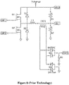
- FIG. 6 shows a resistive charge balancing circuit that is used to discharges cells having a higher voltage until they match the charge voltage of lower voltage cells to balance the charge between the cells.
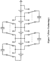
- Figure 7 shows a capacitive charge shuttling circuit used for moving charge from battery cell(s) having a higher voltage to battery cell(s) having a lower voltage.
- Figure 8 shows an inductive charge shuttling circuit used for moving charge from battery cell(s) having a higher voltage to battery cell(s) having a lower voltage.
- Figure 9 shows an inductive switching system that takes charge from higher voltage battery cells and dumps the charge back into the full battery pack.
- Each of these methods removes charge from lower capacity batteries to charge higher capacity cells. The repeated charge/discharge reduces battery life and increases the losses in wasted energy during the battery charging balancing process.
- Document WO 2013088695 A2 discloses a battery cell voltage equalization apparatus, as discussed in the preceding.
- the setup of the reference includes, to equalize respective battery cells of a battery, a switch circuit provided between a charger and the battery and configured to electrically connect or disconnect the charger and the battery; a cell balance circuit configured to equalize the voltage of a plurality of battery cells; and a control unit configured to control the switch circuit using the charging control signal and to control the cell balance circuit using the balance control signal based on a state of the battery.
- the control unit controls the cell balance circuit to equalize the voltage of the plurality of battery cells while controlling the switch circuit so that the charger and the battery are electrically connected, when the charging state of the battery is lower than a prescribed threshold.
- Document US 2014/103857 is another example of prior art.
- the present invention provides battery systems according to claims 1 and 7 ; and methods as defined in claims 12 and 13. Preferred embodiments are defined in dependent claims. The invention is set out in the appended set of claims.
- a multi-cell battery pack charging system adjusts each battery cell's charging current to synchronize the completion of charge.
- the battery pack is charged as a whole.
- the battery pack need only be charged once, and without requiring charge shuttling, resistive charge balancing or inductive charge dumping.
- Charging current to each battery cell is based on voltage matching of the battery cells being charged. Additional charge may be given to higher capacity cells of the battery pack during the voltage matching and charging process.
- Any battery chemistry requiring charge balancing may be charged according to the teachings of this disclosure, for example, but not limited to, Lithium-ion (Li-ion), sealed lead acid, NiMh, NiCad, etc.
- Figure 1 shows a Li-ion battery charging curves.
- Figure 2 shows battery capacity depending on the number of charge cycles.
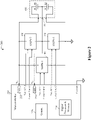
- FIG. 1 depicted is a schematic block diagram of a charging system for a multi-cell battery pack showing voltage and current relationships thereof, according to a specific example embodiment of this disclosure.
- a two-cell battery pack is shown and discussed hereinbelow. It is contemplated and within the scope of this disclosure that a battery pack may comprise more than two battery cells, according to specific embodiments disclosed and claimed herein.
- a battery pack 102 may comprise battery cells B1 and B2, and may further comprise an electrical connector 104 coupled to each terminal (node) of the battery cells B1 and B2.
- a first power supply 106 may be coupled through the electrical connector 104 to a positive terminal of battery cell B1 and a negative terminal of battery cell B2.
- a second power supply 108 may be coupled through the electrical connector 104 to the positive terminal of battery cell B1 and a negative terminal of battery cell B1.
- a third power supply 110 may be coupled through the electrical connector 104 to a positive terminal of battery cell B2 and the negative terminal of battery cell B2.
- the first power supply 106 may provide a first voltage, V 1 , and a first current, I 1 , to the series connected battery cells B1 and B2.
- the first power supply 106 may have operating voltage and current limit set-point inputs.
- the second power supply 108 may operate at a second voltage, V 2 , and provide a second current, I 2 , to the battery cell B1.
- the second power supply 108 may have operating voltage and current limit set-point inputs.
- the third power supply 110 may operate at a third voltage, V 3 , and provide a third current, I 3 , to the battery cell B2.
- the third power supply 110 may have operating voltage and current limit set-point inputs.
- the second power supply 108 may be a floating power supply, e.g., isolated flyback SMPS.
- the third power supply 110 may or may not be a floating power supply since its negative (-) or common node is coupled to the negative (-) or common nodes of the first power supply 106 and the battery pack 102.
- the first power supply 106 may comprise a higher current rated SMPS.
- the second power supply 108 may comprise an isolated lower current rated SMPS, e.g., an isolated flyback SMPS.
- the third power supply 110 may comprise a lower current rated SMPS.
- the second voltage, V 2 is less than the third voltage, V 3
- the first battery cell B1 requires more charge than the second battery cell B2. This is accomplished by the second power supply 108 supplying charging current I 2 to only the first battery cell B1.
- the second power supply 108 is providing the charging current I 2
- the first power supply 108 charging current I 1 will be reduced by the ampere (milliampere) value of the charging current I 2 .
- the second battery cell B2 requires more charge than the first battery cell B1.
- the third power supply 110 is providing the charging current I 3
- the first power supply 108 charging current I 1 will be reduced by the ampere (milliampere) value of the charging current I 3 .
- the charging current to the battery cell B1 will be reduced and thereby not charge as fast as will the battery cell B2.
- the third power supply 110 will cease supplying charging current I 3 and the first power supply 106 will go back to supplying the optimal charging current to both battery cells B1 and B2.
- FIG. 2 illustrates a schematic block diagram of a charging system for a battery pack comprising two battery cells, according to a specific example embodiment of this disclosure.
- a battery pack charging system may comprise a first power supply 106, a second power supply 108, a third power supply 110 and a microcontroller 220.
- a battery pack 102 comprising battery cells B1 and B2 may be coupled to the charging system 200 through an electrical connector 104.
- the first power supply 106 provides charging current and voltage to the series connected battery cells B1 and B2.
- the second power supply 108 provides charging current and voltage to only battery cell B1 when it is providing current.
- the third power supply 110 provides charging current and voltage to only battery cell B2 when it is providing current.
- the first power supply 106 provides charging current at either the optimum charging current rate for the chemistry of the battery cells B1 and B2, or a reduced charging current when one of the other two power supplies 108 or 110 is supplying charging current to its respective battery cell B1 or B2.
- the charging current from the first power supply 106 may be reduced by the charging current value provided by power supply 108 or 110. Therefore, the battery cell having the lower voltage will receive full and optimal charging current until its voltage is substantially the same as the other battery cell. While the other battery cell will receive a lower charging current until both battery cells B1 and B2 are at substantially the same voltage. Then whichever power supply 108 or 110 was supplying charging current will turn off and the first power supply 106 will resume supplying full and optimal charging current to both battery cells B1 and B2.
- the microcontroller 220 may comprise a digital processor and memory 226, a first analog-to-digital converter (ADC) 222, a second ADC 224, voltage set-point outputs 1, 2 and 3; and current limit outputs 1, 2 and 3.
- ADC analog-to-digital converter
- Input power connections are not shown to the microcontroller 220 or power supplies 106, 108 and 110, but one having ordinary skill in the electronic arts and the benefit of this disclosure would understand how to provide the appropriate power connections thereto.
- the voltage set-points and current limit outputs may be digital (e.g., serial or parallel) and/or analog depending upon the input requirements of the power supplies 106, 108 and 110.
- the first power supply 106 may provide most of the charging current to the battery pack 102, and it may be current and voltage limited to provide the necessary current/voltage charging for a specific battery chemistry.
- a battery charging program may reside in the memory of the digital processor and memory 226, and run by the processor to control battery charging operations, according to the teachings of this disclosure.
- the microcontroller 220 may provide all necessary analog and/or digital outputs to the power supplies, and analog inputs for measuring the battery cell voltages.
- the battery charging program may provide for charging many different types of battery packs, whose charging profile may be selected through a communications interface 228, e.g., serial, USB, etc.
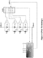
- FIG. 3 illustrates a schematic block diagram of a charging system for a battery pack comprising a plurality of battery cells, according to a specific example embodiment of this disclosure.
- a battery pack charging system may comprise a first high current power supply 106, a second lower current power supply 108, a plurality of lower current power supplies 210n and a microcontroller 320.
- a battery pack 302 may comprise a plurality of battery cells B1 through Bn-1 and may be coupled to the charging system 300 through an electrical connector 304.
- the first power supply 106 provides charging current and voltage to the series connected battery cells B1 through Bn-1.
- the second power supply 108 provides charging current and voltage to only battery cell B1 when it is providing current.
- the plurality of power supplies 210n provide charging current and voltage to an associated battery cell B2 to Bn-1 when it is providing current thereto, where n is the number of battery cells minus 1.
- the first power supply 106 provides charging current at either the optimum charging current rate for the chemistry of the battery cells B1 through Bn-1, or a reduced charging current when one or more of the other power supplies 108 or 210n is supplying charging current to its respective battery cell B1 or B2 to Bn-1.
- the charging current from the first power supply 106 may be reduced by the charging current value provided by power supply 108 and/or 210n. Therefore, the battery cell(s) having the lower voltage(s) will receive full and optimal charging current until its (their) voltage(s) is (are) substantially the same as the other battery cells. While the other battery cells will receive a lower charging current until all battery cells B1 through Bn-1 are at substantially the same voltage.
- More than one lower current power supply may be supplying current to its associated battery cell when those battery cells have a lower voltage then some other ones of the plurality of battery cells.
- the microcontroller 320 may comprise a digital processor and memory 226, a first analog-to-digital converter (ADC) 322, a second ADC 324, a plurality of ADCs 326n-1, voltage set-point outputs 1 through n, and current limit outputs 1 through n.
- Input power connections are not shown to the microcontroller 320 or power supplies 106, 108 and the plurality of power supplies 210n, but one having ordinary skill in the electronic arts and the benefit of this disclosure would understand how to provide the appropriate power connections thereto.
- the voltage set-points and current limit outputs may be digital (e.g., serial or parallel) and/or analog depending upon the input requirements of the power supplies 106, 108 and the plurality of power supplies 210n.
- a single ADC and sample and hold multiplexer (not shown) may be used instead of a plurality of ADCs.
- the first power supply 106 may provide most of the charging current to the battery pack 302, it may be current and voltage limited to provide the necessary current/voltage charging for a specific battery chemistry.
- ADCs 322, 324 and a plurality of ADCs 326n-1 monitor the voltages across the battery cells B1 through Bn-1, and when a difference between these voltages is detected, the balanced charging system is enabled. Based on the difference in individual battery cell voltages, the current drive of the high current charge from the power supply 106 is reduced, and the appropriate power supply(ies) 108 and/or 210n may be enabled at a current output substantially equal to the reduction in the high current charger. In this way, the charging currents for each battery cell may be adjusted to bring the battery cell voltages to be substantially the same. If/when the battery cells charge to substantially the same voltage, then the power supply 108 or 110 may be shut down and the high current charge from the power supply 106 returns to its normal current limit.
- a battery charging program may reside in the memory of the digital processor and memory 226, and run by the processor thereof to control battery charging operations, according to the teachings of this disclosure.
- the microcontroller 320 may provide all necessary analog and/or digital outputs to the power supplies, and analog inputs for measuring the battery cell voltages.
- the battery charging program may provide for charging many different types of battery packs, whose charging profile may be selected through a communications interface 228, e.g., serial, USB, etc.
- each battery cell is charged once and the battery life is thereby maximized.
- Each battery cell is fully charged and no battery cell is over charged in the battery pack, whereby the charge time is optimized. Because charge current is never removed from a battery, the losses in battery life and heating due to repetitive charge and discharge of prior technology charge balancing systems are avoided.
- the voltage difference is charge and chemistry dependent. So, when one battery is low in voltage, then the amount of current would be added to just that battery and may be determined by the charge curves for that battery chemistry. This is just a starting point though, the system can keep track of the voltage increase during charging and if it remained low, then the current to the low cell could be increased. How much and how long would depend upon the chemistry, capacity of the cell, and probably temperature.
Landscapes
- Engineering & Computer Science (AREA)
- Power Engineering (AREA)
- Chemical & Material Sciences (AREA)
- Chemical Kinetics & Catalysis (AREA)
- Electrochemistry (AREA)
- General Chemical & Material Sciences (AREA)
- Manufacturing & Machinery (AREA)
- Charge And Discharge Circuits For Batteries Or The Like (AREA)
- Secondary Cells (AREA)
Description
- The present disclosure relates to battery charging systems, and, in particular, to multi-cell battery pack charging systems.
- When charging multi-cell battery packs each battery cell must not be over or under charged. This requires charge balancing of the multi-cell battery pack. There are four different methods for charge balancing of a multi-cell Battery Pack: 1)
Figure 6 shows a resistive charge balancing circuit that is used to discharges cells having a higher voltage until they match the charge voltage of lower voltage cells to balance the charge between the cells. 2)Figure 7 shows a capacitive charge shuttling circuit used for moving charge from battery cell(s) having a higher voltage to battery cell(s) having a lower voltage. 3)Figure 8 shows an inductive charge shuttling circuit used for moving charge from battery cell(s) having a higher voltage to battery cell(s) having a lower voltage. And 4)Figure 9 shows an inductive switching system that takes charge from higher voltage battery cells and dumps the charge back into the full battery pack. Each of these methods removes charge from lower capacity batteries to charge higher capacity cells. The repeated charge/discharge reduces battery life and increases the losses in wasted energy during the battery charging balancing process. - Document
WO 2013088695 A2 discloses a battery cell voltage equalization apparatus, as discussed in the preceding. The setup of the reference includes, to equalize respective battery cells of a battery, a switch circuit provided between a charger and the battery and configured to electrically connect or disconnect the charger and the battery; a cell balance circuit configured to equalize the voltage of a plurality of battery cells; and a control unit configured to control the switch circuit using the charging control signal and to control the cell balance circuit using the balance control signal based on a state of the battery. The control unit controls the cell balance circuit to equalize the voltage of the plurality of battery cells while controlling the switch circuit so that the charger and the battery are electrically connected, when the charging state of the battery is lower than a prescribed threshold. DocumentUS 2014/103857 is another example of prior art. - There are two main problems with the aforementioned battery charging methods: One, existing charge balancing methods result in a reduction of charge life typically expected with the individual battery cells. Two, existing charge balancing systems move charge already in a cell, to another cell resulting in losses due to the internal resistance of the cell.
- Hence, there is a need for an improved battery charging system for multi-cell battery packs.
- The present invention provides battery systems according to
claims claims - A more complete understanding of the present disclosure may be acquired by referring to the following description taken in conjunction with the accompanying drawings wherein:
-
Figure 1 illustrates a schematic block diagram of a charging system for a multi-cell battery pack showing voltage and current relationships thereof, according to a specific example embodiment of this disclosure; -
Figure 2 illustrates a schematic block diagram of a charging system for a battery pack comprising two battery cells, according to a specific example embodiment of this disclosure; -
Figure 3 illustrates a schematic block diagram of a charging system for a battery pack comprising a plurality of battery cells, according to a specific example embodiment of this disclosure; -
Figure 4 illustrates a graphical representation of Li-Ion battery charging curves; -
Figure 5 illustrates a graphical representation of battery capacity resulting from the number of charge cycles; -
Figure 6 illustrates a schematic diagram of a resistive charge balancing circuit used for discharging battery cells having a higher voltage until they match the charge voltage of lower voltage battery cells to balance the charge between the battery cells; -
Figure 7 illustrates a schematic diagram of a capacitive charge shuttling circuit used for moving charge from battery cell(s) having a higher voltage to battery cell(s) having a lower voltage; -
Figure 8 illustrates a schematic diagram of an inductive charge shuttling circuit used for moving charge from battery cell(s) having a higher voltage to battery cell(s) having a lower voltage; and -
Figure 9 illustrates a schematic diagram of an inductive switching system that takes charge from higher voltage battery cells and dumps the charge back into the full battery pack. - While the present disclosure is susceptible to various modifications and alternative forms, specific example embodiments thereof have been shown in the drawings and are herein described in detail. It should be understood, however, that the description herein of specific example embodiments is not intended to limit the disclosure to the forms disclosed herein.
- According to various embodiments, a multi-cell battery pack charging system adjusts each battery cell's charging current to synchronize the completion of charge. According to various embodiments, the battery pack is charged as a whole. The battery pack need only be charged once, and without requiring charge shuttling, resistive charge balancing or inductive charge dumping. Charging current to each battery cell is based on voltage matching of the battery cells being charged. Additional charge may be given to higher capacity cells of the battery pack during the voltage matching and charging process. Any battery chemistry requiring charge balancing may be charged according to the teachings of this disclosure, for example, but not limited to, Lithium-ion (Li-ion), sealed lead acid, NiMh, NiCad, etc.
Figure 1 shows a Li-ion battery charging curves.Figure 2 shows battery capacity depending on the number of charge cycles. - Referring now to the drawings, the details of example embodiments are schematically illustrated. Like elements in the drawings will be represented by like numbers, and similar elements will be represented by like numbers with a different lower case letter suffix.
- Referring to
Figure 1 , depicted is a schematic block diagram of a charging system for a multi-cell battery pack showing voltage and current relationships thereof, according to a specific example embodiment of this disclosure. For descriptive purposes a two-cell battery pack is shown and discussed hereinbelow. It is contemplated and within the scope of this disclosure that a battery pack may comprise more than two battery cells, according to specific embodiments disclosed and claimed herein. - A
battery pack 102 may comprise battery cells B1 and B2, and may further comprise anelectrical connector 104 coupled to each terminal (node) of the battery cells B1 and B2. Afirst power supply 106 may be coupled through theelectrical connector 104 to a positive terminal of battery cell B1 and a negative terminal of battery cell B2. Asecond power supply 108 may be coupled through theelectrical connector 104 to the positive terminal of battery cell B1 and a negative terminal of battery cell B1. Athird power supply 110 may be coupled through theelectrical connector 104 to a positive terminal of battery cell B2 and the negative terminal of battery cell B2. - The
first power supply 106 may provide a first voltage, V1, and a first current, I1, to the series connected battery cells B1 and B2. Thefirst power supply 106 may have operating voltage and current limit set-point inputs. Thesecond power supply 108 may operate at a second voltage, V2, and provide a second current, I2, to the battery cell B1. Thesecond power supply 108 may have operating voltage and current limit set-point inputs. Thethird power supply 110 may operate at a third voltage, V3, and provide a third current, I3, to the battery cell B2. Thethird power supply 110 may have operating voltage and current limit set-point inputs. - The sum of the second voltage, V2, and the third voltage, V3, equal the first voltage, V1. Current relationships for the first, second and third currents, I1, I2 and I3, respectively, are shown in
Figure 1 . Thesecond power supply 108 may be a floating power supply, e.g., isolated flyback SMPS. Thethird power supply 110 may or may not be a floating power supply since its negative (-) or common node is coupled to the negative (-) or common nodes of thefirst power supply 106 and thebattery pack 102. Thefirst power supply 106 may comprise a higher current rated SMPS. Thesecond power supply 108 may comprise an isolated lower current rated SMPS, e.g., an isolated flyback SMPS. Thethird power supply 110 may comprise a lower current rated SMPS. - When the second voltage, V2, and the third voltage, V3, are substantially equal the
second power supply 108 andthird power supply 110 do not supply current (I2 = I3 = 0), and thefirst power supply 106 alone supplies an optimal charging current I1 to thebattery pack 102 at the first voltage, V1. When the second voltage, V2, is less than the third voltage, V3, the first battery cell B1 requires more charge than the second battery cell B2. This is accomplished by thesecond power supply 108 supplying charging current I2 to only the first battery cell B1. When thesecond power supply 108 is providing the charging current I2, thefirst power supply 108 charging current I1 will be reduced by the ampere (milliampere) value of the charging current I2. This maintains the optimal charging current for the battery cell B1. The charging current to the battery cell B2 will be reduced and thereby not charge as fast as will the battery cell B1. These two different battery cell charging currents will be maintained until the second voltage, V2, is again substantially equal to the third voltage, V3. Then thesecond power supply 108 will cease supplying charging current I2 and thefirst power supply 106 will go back to supplying the optimal charging current to both battery cells B1 and B2. - In a similar fashion when the second voltage, V2, is greater than the third voltage, V3, the second battery cell B2 requires more charge than the first battery cell B1. This is accomplished by the
third power supply 110 supplying charging current I3 to only the second battery cell B2. When thethird power supply 110 is providing the charging current I3, thefirst power supply 108 charging current I1 will be reduced by the ampere (milliampere) value of the charging current I3. This maintains the optimal charging current for the battery cell B2. The charging current to the battery cell B1 will be reduced and thereby not charge as fast as will the battery cell B2. These two different battery cell charging currents will be maintained until the second voltage, V2, is again substantially equal to the third voltage, V3. Then thethird power supply 110 will cease supplying charging current I3 and thefirst power supply 106 will go back to supplying the optimal charging current to both battery cells B1 and B2. -
Figure 2 illustrates a schematic block diagram of a charging system for a battery pack comprising two battery cells, according to a specific example embodiment of this disclosure. A battery pack charging system, generally represented by the numeral 200, may comprise afirst power supply 106, asecond power supply 108, athird power supply 110 and amicrocontroller 220. Abattery pack 102 comprising battery cells B1 and B2 may be coupled to thecharging system 200 through anelectrical connector 104. Thefirst power supply 106 provides charging current and voltage to the series connected battery cells B1 and B2. Thesecond power supply 108 provides charging current and voltage to only battery cell B1 when it is providing current. Thethird power supply 110 provides charging current and voltage to only battery cell B2 when it is providing current. - At all times the
first power supply 106 provides charging current at either the optimum charging current rate for the chemistry of the battery cells B1 and B2, or a reduced charging current when one of the other twopower supplies first power supply 106 may be reduced by the charging current value provided bypower supply power supply first power supply 106 will resume supplying full and optimal charging current to both battery cells B1 and B2. - The
microcontroller 220 may comprise a digital processor andmemory 226, a first analog-to-digital converter (ADC) 222, asecond ADC 224, voltage set-point outputs current limit outputs microcontroller 220 orpower supplies - The
first power supply 106 may provide most of the charging current to thebattery pack 102, and it may be current and voltage limited to provide the necessary current/voltage charging for a specific battery chemistry. TwoADCs power supply 106 is reduced, and theappropriate power supply power supply power supply 106 returns to its normal current limit. - A battery charging program may reside in the memory of the digital processor and
memory 226, and run by the processor to control battery charging operations, according to the teachings of this disclosure. In addition, themicrocontroller 220 may provide all necessary analog and/or digital outputs to the power supplies, and analog inputs for measuring the battery cell voltages. The battery charging program may provide for charging many different types of battery packs, whose charging profile may be selected through acommunications interface 228, e.g., serial, USB, etc. -
Figure 3 illustrates a schematic block diagram of a charging system for a battery pack comprising a plurality of battery cells, according to a specific example embodiment of this disclosure. A battery pack charging system, generally represented by the numeral 300, may comprise a first highcurrent power supply 106, a second lowercurrent power supply 108, a plurality of lowercurrent power supplies 210n and amicrocontroller 320. Abattery pack 302 may comprise a plurality of battery cells B1 through Bn-1 and may be coupled to thecharging system 300 through anelectrical connector 304. Thefirst power supply 106 provides charging current and voltage to the series connected battery cells B1 through Bn-1. Thesecond power supply 108 provides charging current and voltage to only battery cell B1 when it is providing current. The plurality ofpower supplies 210n provide charging current and voltage to an associated battery cell B2 to Bn-1 when it is providing current thereto, where n is the number of battery cells minus 1. - At all times the
first power supply 106 provides charging current at either the optimum charging current rate for the chemistry of the battery cells B1 through Bn-1, or a reduced charging current when one or more of theother power supplies first power supply 106 may be reduced by the charging current value provided bypower supply 108 and/or 210n. Therefore, the battery cell(s) having the lower voltage(s) will receive full and optimal charging current until its (their) voltage(s) is (are) substantially the same as the other battery cells. While the other battery cells will receive a lower charging current until all battery cells B1 through Bn-1 are at substantially the same voltage. Then whichever power supply(ies) 108 or 210n was (were) supplying charging current will turn off and thefirst power supply 106 will resume supplying full and optimal charging current to the battery cells B1 through Bn-1. More than one lower current power supply may be supplying current to its associated battery cell when those battery cells have a lower voltage then some other ones of the plurality of battery cells. - The
microcontroller 320 may comprise a digital processor andmemory 226, a first analog-to-digital converter (ADC) 322, asecond ADC 324, a plurality ofADCs 326n-1, voltage set-point outputs 1 through n, andcurrent limit outputs 1 through n. Input power connections are not shown to themicrocontroller 320 orpower supplies power supplies 210n, but one having ordinary skill in the electronic arts and the benefit of this disclosure would understand how to provide the appropriate power connections thereto. The voltage set-points and current limit outputs may be digital (e.g., serial or parallel) and/or analog depending upon the input requirements of the power supplies 106, 108 and the plurality ofpower supplies 210n. A single ADC and sample and hold multiplexer (not shown) may be used instead of a plurality of ADCs. - The
first power supply 106 may provide most of the charging current to thebattery pack 302, it may be current and voltage limited to provide the necessary current/voltage charging for a specific battery chemistry.ADCs ADCs 326n-1 monitor the voltages across the battery cells B1 through Bn-1, and when a difference between these voltages is detected, the balanced charging system is enabled. Based on the difference in individual battery cell voltages, the current drive of the high current charge from thepower supply 106 is reduced, and the appropriate power supply(ies) 108 and/or 210n may be enabled at a current output substantially equal to the reduction in the high current charger. In this way, the charging currents for each battery cell may be adjusted to bring the battery cell voltages to be substantially the same. If/when the battery cells charge to substantially the same voltage, then thepower supply power supply 106 returns to its normal current limit. - A battery charging program may reside in the memory of the digital processor and
memory 226, and run by the processor thereof to control battery charging operations, according to the teachings of this disclosure. In addition, themicrocontroller 320 may provide all necessary analog and/or digital outputs to the power supplies, and analog inputs for measuring the battery cell voltages. The battery charging program may provide for charging many different types of battery packs, whose charging profile may be selected through acommunications interface 228, e.g., serial, USB, etc. - In the embodiments disclosed and claimed herein, each battery cell is charged once and the battery life is thereby maximized. Each battery cell is fully charged and no battery cell is over charged in the battery pack, whereby the charge time is optimized. Because charge current is never removed from a battery, the losses in battery life and heating due to repetitive charge and discharge of prior technology charge balancing systems are avoided.
- Conventional prior technology charge balancing systems are designed to operate outside the normal charging algorithms used to charge multi-cell battery packs. Only the use of an intelligent charger as provided by the various embodiments disclosed and claimed herein and having the ability to adaptively charge individual battery cells would be able to implement a battery charging system that does not suffer from the deficiencies of the prior technology multi-cell battery pack charging systems.
- The voltage difference is charge and chemistry dependent. So, when one battery is low in voltage, then the amount of current would be added to just that battery and may be determined by the charge curves for that battery chemistry. This is just a starting point though, the system can keep track of the voltage increase during charging and if it remained low, then the current to the low cell could be increased. How much and how long would depend upon the chemistry, capacity of the cell, and probably temperature.
Claims (15)
- A battery charging system for charging a plurality of series connected battery cells in a battery pack without removing charge current from the battery cells, said system comprising:a first electrical connector adapted for coupling to a second electrical connector of a battery pack (102, 302), said battery pack (102, 302) comprising a plurality of battery cells (B1, B2, Bn-1) coupled in series, wherein each electrical node of the plurality of battery cells (B1, B2, Bn-1) is coupled to a respective one of a plurality of electrical contacts of the second electrical connector;a first power supply (106) having voltage set-point and a current limit inputs, where plus and minus outputs from the first power supply (106) are coupled to respective electrical contacts of the first electrical connector that match plus and minus electrical contacts of the second connector, so that a first power supply charging current is provided to all of the series connected plurality of battery cells (B1, B2, Bn-1) ;a plurality of second power supplies (108, 110), each having voltage set-point and a current limit inputs, where plus and minus outputs from each of the plurality of second power supplies are coupled through the electrical connectors to associated terminals of the plurality of battery cells (B1, B2, Bn-1), wherein each one of the plurality of second power supplies is configured to supply a charging current to only the one battery cell (B1, B2, Bn-1) associated therewith;voltage measurement means configured to measure voltages of each of the plurality of battery cells (B1, B2, Bn-1); andcharacterised in that the said system further comprising a charge control unit (220) configured to charge the series connected plurality of battery cells (B1, B2, Bn-1) with the first power supply charging current from the first power supply (106) and upon detection of a difference between battery cell voltages to individually charge battery cells (B1, B2, Bn-1) having a lower voltage than the other battery cells (B1, B2, Bn-1) with additional charging currents from the associated second power supplies (108, 110) of the plurality of second power supplies (108, 110), wherein when additional charging currents from the second power supplies (108, 110) are applied a current limiting control scheme is configured to reduce the first power supply charging current based on the amount of the additional charging currents from the second power supplies (108, 110) as long as the there is a difference in battery cell voltages.
- The battery charging system according to claim 1, wherein the voltage measurement means comprises a plurality of analog-to-digital converters (DACs) coupled to voltage nodes of the series coupled plurality of battery cells (B1, B2, Bn-1) or wherein the voltage measurement means comprises an analog-to-digital converter (ADC) and a multiplexer coupled between the voltage nodes of the series coupled plurality of battery cells (B1, B2, Bn-1) and the ADC.
- The battery charging system according to any of claims 1-2, wherein the first power supply (106) is a high current switched-mode power supply, and the plurality of second power supplies (108, 110) are isolated flyback switched mode power supplies.
- The battery charging system according to any of claims 1-3, wherein a microcontroller (220) is configured to provide:voltage set-point and current limit signals to the first power supply (106) and the plurality of second power supplies (108, 110);the voltage measurement means for measuring voltage of each of the plurality of battery cells (B1, B2, Bn-1); anda digital processor and memory for running battery charging programs and controlling the first power supply voltage set-point and current limit, and controlling the plurality of second power supplies voltage set-points and current limits.
- The battery charging system according to claim 4, further comprising a microcontroller communications port coupled to the digital processor for providing battery charging profiles and battery charging status.
- The battery charging system according to any of claims 1-5, wherein the plurality of battery cells (B1, B2, Bn-1) are selected from the group consisting of Lithium-ion (Li-Ion) battery cells, sealed lead acid, NiMh, and NiCad.
- A battery charging system for charging two series connected battery cells in a battery pack without removing charge current from the battery cells (B1, B2, Bn-1), said system comprising:a first electrical connector adapted for coupling to a second electrical connector of a battery pack (102, 302), said battery pack (102, 302) comprising first and second battery cells (B1, B2) coupled in series, wherein each electrical node of the first and second battery cells (B1, B2) is coupled to a respective one of a plurality of electrical contacts of the second electrical connector;a first power supply (106) having a voltage set-point and a current limit inputs, where plus and minus outputs from the first power supply (106) are coupled to respective electrical contacts of the first electrical connector that match plus and minus electrical contacts of the second connector, so that a first power supply charging current is provided to both of the first and second battery cells (B1, B2, Bn-1) connected in series;a second power supply (108) having a voltage set-point and a current limit input, where plus and minus outputs from the second power supply (108) are coupled only to the associated terminals of the first battery cell (B1);a third power supply (110) having a voltage set-point and a current limit input, where plus and minus outputs from the third power supply (110) are coupled only to the associated terminals of the second battery cell (B2);voltage measurement means configured to measure voltages of the first and second battery cells (B1, B2); andcharacterised in that the said system further comprising a charge control unit (220) configured to charge the series connected first and second battery cells (B1, B2) with the first power supply charging current from the first power supply (106) and upon detection of a difference between the first and second battery cell voltages to individually charge the battery cell (B1, B2) having a lower voltage than the other battery cell (B2, B1) with additional charging currents from the associated second or third power supply (108, 110), wherein when additional charging current from the second or third power supply (108, 110) are applied a current limiting control scheme is configured to reduce the first power supply charging current based on the amount of the charging current from the second or third power supply (108, 110) as long as there is a difference between battery cell voltages.
- The battery charging system according to claim 7, wherein the voltage measurement means comprises at least two analog-to-digital converters (DACs) coupled to voltage nodes of the series coupled first and second battery cells (B1, B2) or wherein the voltage measurement means comprises an analog-to-digital converter (ADC) and a multiplexer coupled between the voltage nodes of the series coupled first and second battery cells (B1, B2) and the ADC.
- The battery charging system according to any of claims 7-8, wherein the first power supply (106) is a high current switched-mode power supply, and the second and third power supplies (108, 110) are isolated flyback switched mode power supplies.
- The battery charging system according to any of claims 7-9, wherein a microcontroller (220) is configured to provide:voltage set-point and current limit signals to the first, second and third power supplies (106, 108, 110);the voltage measurement means for measuring voltages of the first and second battery cells (B1, B2); anda digital processor and memory for running battery charging programs and controlling the first, second and third power supply voltage set-points and current limits.
- The battery charging system according to claim 10, further comprising a microcontroller communications port coupled to the digital processor for providing battery charging profiles and battery charging status.
- A method for charging a battery pack comprising a plurality of battery cells without removing charge current from the battery cells, said method comprising the steps of:setting desired voltage set-point and current limit values into a high current power supply (106) for a plurality of series connected battery cells (B1, B2, Bn-1) in a battery pack (102, 302), wherein the high current power supply (106) provides charging voltage and current to the plurality of series connected battery cells (B1, B2, Bn-1) in the battery pack (102, 302);determining a voltage of each one of the plurality of series connected battery cells (B1, B2, Bn-1) in the battery pack (102, 302);characterised in that if any one or more of the battery cells (B1, B2, Bn-1) has a voltage that is not substantially the same as the other battery cells (B1, B2, Bn-1) thenif that voltage is less than the other battery cell voltages then increase current from another power supply (108, 110) coupled to that battery cell (B1, B2, Bn-1) and reduce the current limit value of the high current power supply (106) by the value of the current from the other power supply (108, 110), andif the voltage is greater than the other battery cells (B1, B2, Bn-1) then increase the current to the other battery cells (B1, B2, Bn-1) with other associated power supplies (108, 110) coupled to the other ones of the plurality of series connected battery cells (B1, B2, Bn-1), and reduce the current limit value of the high current power supply (106) by the value of the currents from the other associated power supplies (108, 110).
- A method for charging a battery pack comprising two battery cells without removing charge current from the battery cells, said method comprising the steps of:setting desired voltage set-point and current limit values into a high current power supply for first and second battery cells in a battery pack and connected series, wherein the first high current power supply provides the desired voltage and current to the first and second series connected battery cells in the battery pack; anddetermining a first voltage of the first battery cell and a second voltage of the second battery cell;characterised in thatif the first voltage is greater than the second voltage then increase current from a second power supply coupled to the first battery cell and reduce the current limit value of the high current power supply by the value of the current from the second power supply, andif the first voltage is less than the second voltage then increase current from a third power supply coupled to the second battery cell and reduce the current limit value of the high current power supply by the value of the current from the third power supply.
- The method according to claim 13, wherein the second and third power supplies provide substantially no currents when the first and second voltages are substantially equal.
- The method according to any of claims 13-14, wherein the second power supply provides substantially no current when the first voltage is greater than the second voltage and/or wherein the third power supply provides substantially no current when the first voltage is less than the second voltage.
Applications Claiming Priority (3)
| Application Number | Priority Date | Filing Date | Title |
|---|---|---|---|
| US201662320708P | 2016-04-11 | 2016-04-11 | |
| US15/483,685 US10283973B2 (en) | 2016-04-11 | 2017-04-10 | Balanced battery charging system |
| PCT/US2017/026971 WO2017180599A1 (en) | 2016-04-11 | 2017-04-11 | Balanced battery charging system |
Publications (2)
| Publication Number | Publication Date |
|---|---|
| EP3443635A1 EP3443635A1 (en) | 2019-02-20 |
| EP3443635B1 true EP3443635B1 (en) | 2022-08-24 |
Family
ID=59998338
Family Applications (1)
| Application Number | Title | Priority Date | Filing Date |
|---|---|---|---|
| EP17719779.5A Active EP3443635B1 (en) | 2016-04-11 | 2017-04-11 | Balanced battery charging system |
Country Status (5)
| Country | Link |
|---|---|
| US (1) | US10283973B2 (en) |
| EP (1) | EP3443635B1 (en) |
| CN (1) | CN108432085B (en) |
| TW (1) | TW201743533A (en) |
| WO (1) | WO2017180599A1 (en) |
Families Citing this family (2)
| Publication number | Priority date | Publication date | Assignee | Title |
|---|---|---|---|---|
| WO2018081912A1 (en) * | 2016-11-07 | 2018-05-11 | Corvus Energy Inc. | Balancing a multi-cell battery |
| EP3804078A4 (en) | 2018-05-30 | 2022-02-23 | Milwaukee Electric Tool Corporation | Fast-charging battery pack |
Citations (1)
| Publication number | Priority date | Publication date | Assignee | Title |
|---|---|---|---|---|
| US20140103857A1 (en) * | 2011-06-11 | 2014-04-17 | Sendyne Corp. | Charge redistribution method for cell arrays |
Family Cites Families (18)
| Publication number | Priority date | Publication date | Assignee | Title |
|---|---|---|---|---|
| US6009344A (en) * | 1997-07-25 | 1999-12-28 | Becton, Dickinson And Company | Iontophoretic drug delivery system |
| US6172480B1 (en) * | 1998-10-23 | 2001-01-09 | Primetech Electronics, Inc. | Compact fast battery charger |
| TW502900U (en) | 1998-11-30 | 2002-09-11 | Ind Tech Res Inst | Battery charging equalizing device |
| US7589500B2 (en) * | 2002-11-22 | 2009-09-15 | Milwaukee Electric Tool Corporation | Method and system for battery protection |
| CN100505471C (en) * | 2004-01-14 | 2009-06-24 | 财团法人工业技术研究院 | Equating circuit for serial battery |
| JP4148162B2 (en) * | 2004-03-05 | 2008-09-10 | 株式会社デンソー | Circuit system |
| US7460930B1 (en) * | 2004-05-14 | 2008-12-02 | Admmicro Properties, Llc | Energy management system and method to monitor and control multiple sub-loads |
| US7688029B2 (en) * | 2005-11-08 | 2010-03-30 | Eveready Battery Company, Inc. | Portable battery powered appliance and method of operation |
| WO2007100035A1 (en) * | 2006-03-03 | 2007-09-07 | Nec Corporation | Power supply system |
| WO2008137764A1 (en) | 2007-05-03 | 2008-11-13 | Sendyne Corporation | Fine-controlled battery-charging system |
| US8193768B2 (en) * | 2008-02-28 | 2012-06-05 | Jason S. Hallett | Contactless charging system for musical instruments |
| JP2010068571A (en) * | 2008-09-09 | 2010-03-25 | Hitachi Koki Co Ltd | Charging apparatus |
| EP2541724A4 (en) * | 2010-02-26 | 2015-11-25 | Toyota Motor Co Ltd | Vehicle |
| JP6030820B2 (en) * | 2010-11-05 | 2016-11-24 | ミツミ電機株式会社 | Battery voltage monitoring circuit |
| JP2013123344A (en) | 2011-12-12 | 2013-06-20 | Toyota Industries Corp | Device for equalizing battery cell voltages |
| FR2986075B1 (en) | 2012-01-25 | 2015-07-17 | Accuwatt | DEVICE FOR MANAGING THE CHARGING OF A HIGH-PRECISION BATTERY, AND METHOD IMPLEMENTED THEREBY. |
| US20130214739A1 (en) * | 2012-02-20 | 2013-08-22 | Jia-Yuan Lee | Charge type battery management system and method thereof |
| CN103607001A (en) * | 2013-11-04 | 2014-02-26 | 江苏嘉钰新能源技术有限公司 | Battery shunt equalization method |
-
2017
- 2017-04-10 US US15/483,685 patent/US10283973B2/en active Active
- 2017-04-11 TW TW106112006A patent/TW201743533A/en unknown
- 2017-04-11 EP EP17719779.5A patent/EP3443635B1/en active Active
- 2017-04-11 WO PCT/US2017/026971 patent/WO2017180599A1/en active Application Filing
- 2017-04-11 CN CN201780005573.5A patent/CN108432085B/en active Active
Patent Citations (1)
| Publication number | Priority date | Publication date | Assignee | Title |
|---|---|---|---|---|
| US20140103857A1 (en) * | 2011-06-11 | 2014-04-17 | Sendyne Corp. | Charge redistribution method for cell arrays |
Also Published As
| Publication number | Publication date |
|---|---|
| WO2017180599A1 (en) | 2017-10-19 |
| TW201743533A (en) | 2017-12-16 |
| CN108432085A (en) | 2018-08-21 |
| US20170294788A1 (en) | 2017-10-12 |
| EP3443635A1 (en) | 2019-02-20 |
| US10283973B2 (en) | 2019-05-07 |
| CN108432085B (en) | 2023-08-29 |
Similar Documents
| Publication | Publication Date | Title |
|---|---|---|
| EP3185388B1 (en) | Battery control method and apparatus, and battery pack | |
| US7928691B2 (en) | Method and system for cell equalization with isolated charging sources | |
| EP2418751B1 (en) | Battery charger and battery charging method | |
| US20170288417A1 (en) | Fast Charging Apparatus and Method | |
| EP2419987B1 (en) | Battery systems and operational methods | |
| US9444267B2 (en) | Cell voltage equalizer for multi-cell battery pack which determines the waiting time between equalization operations based on the voltage difference and the state of charge level | |
| CN100456598C (en) | Battery charging method | |
| US8476869B2 (en) | Battery voltage equalizer circuit and method for using the same | |
| JP5618986B2 (en) | Charger | |
| US11277012B2 (en) | Battery control unit and battery system | |
| US20090267565A1 (en) | Method and system for cell equalization with charging sources and shunt regulators | |
| US20130141034A1 (en) | Charging management system and charger with the same | |
| US20060097697A1 (en) | Method and system for cell equalization with switched charging sources | |
| CN103036268A (en) | Power supply device | |
| US20150048795A1 (en) | Charge control apparatus and charge control method | |
| JP2021057988A (en) | Battery control unit and battery system | |
| EP3443635B1 (en) | Balanced battery charging system | |
| WO2019188889A1 (en) | Power storage system and charging control method | |
| KR20190051483A (en) | Charging control apparatus and method for the same | |
| JP2008067486A (en) | Charging method | |
| US20120256593A1 (en) | Cell charge management system | |
| KR102008518B1 (en) | Charging system for multi-cell | |
| JPH03173323A (en) | Secondary battery charger | |
| US9634499B2 (en) | Adjusting device, battery pack device, and adjusting method | |
| KR100574037B1 (en) | Battery charger capable of individual charging |
Legal Events
| Date | Code | Title | Description |
|---|---|---|---|
| STAA | Information on the status of an ep patent application or granted ep patent |
Free format text: STATUS: UNKNOWN |
|
| STAA | Information on the status of an ep patent application or granted ep patent |
Free format text: STATUS: THE INTERNATIONAL PUBLICATION HAS BEEN MADE |
|
| PUAI | Public reference made under article 153(3) epc to a published international application that has entered the european phase |
Free format text: ORIGINAL CODE: 0009012 |
|
| STAA | Information on the status of an ep patent application or granted ep patent |
Free format text: STATUS: REQUEST FOR EXAMINATION WAS MADE |
|
| 17P | Request for examination filed |
Effective date: 20181112 |
|
| AK | Designated contracting states |
Kind code of ref document: A1 Designated state(s): AL AT BE BG CH CY CZ DE DK EE ES FI FR GB GR HR HU IE IS IT LI LT LU LV MC MK MT NL NO PL PT RO RS SE SI SK SM TR |
|
| AX | Request for extension of the european patent |
Extension state: BA ME |
|
| DAV | Request for validation of the european patent (deleted) | ||
| DAX | Request for extension of the european patent (deleted) | ||
| STAA | Information on the status of an ep patent application or granted ep patent |
Free format text: STATUS: EXAMINATION IS IN PROGRESS |
|
| 17Q | First examination report despatched |
Effective date: 20200909 |
|
| STAA | Information on the status of an ep patent application or granted ep patent |
Free format text: STATUS: EXAMINATION IS IN PROGRESS |
|
| STAA | Information on the status of an ep patent application or granted ep patent |
Free format text: STATUS: EXAMINATION IS IN PROGRESS |
|
| GRAP | Despatch of communication of intention to grant a patent |
Free format text: ORIGINAL CODE: EPIDOSNIGR1 |
|
| STAA | Information on the status of an ep patent application or granted ep patent |
Free format text: STATUS: GRANT OF PATENT IS INTENDED |
|
| INTG | Intention to grant announced |
Effective date: 20220316 |
|
| GRAS | Grant fee paid |
Free format text: ORIGINAL CODE: EPIDOSNIGR3 |
|
| GRAA | (expected) grant |
Free format text: ORIGINAL CODE: 0009210 |
|
| STAA | Information on the status of an ep patent application or granted ep patent |
Free format text: STATUS: THE PATENT HAS BEEN GRANTED |
|
| AK | Designated contracting states |
Kind code of ref document: B1 Designated state(s): AL AT BE BG CH CY CZ DE DK EE ES FI FR GB GR HR HU IE IS IT LI LT LU LV MC MK MT NL NO PL PT RO RS SE SI SK SM TR |
|
| REG | Reference to a national code |
Ref country code: CH Ref legal event code: EP |
|
| REG | Reference to a national code |
Ref country code: IE Ref legal event code: FG4D |
|
| REG | Reference to a national code |
Ref country code: AT Ref legal event code: REF Ref document number: 1514332 Country of ref document: AT Kind code of ref document: T Effective date: 20220915 Ref country code: DE Ref legal event code: R096 Ref document number: 602017060974 Country of ref document: DE |
|
| REG | Reference to a national code |
Ref country code: LT Ref legal event code: MG9D |
|
| REG | Reference to a national code |
Ref country code: NL Ref legal event code: MP Effective date: 20220824 |
|
| PG25 | Lapsed in a contracting state [announced via postgrant information from national office to epo] |
Ref country code: SE Free format text: LAPSE BECAUSE OF FAILURE TO SUBMIT A TRANSLATION OF THE DESCRIPTION OR TO PAY THE FEE WITHIN THE PRESCRIBED TIME-LIMIT Effective date: 20220824 Ref country code: RS Free format text: LAPSE BECAUSE OF FAILURE TO SUBMIT A TRANSLATION OF THE DESCRIPTION OR TO PAY THE FEE WITHIN THE PRESCRIBED TIME-LIMIT Effective date: 20220824 Ref country code: PT Free format text: LAPSE BECAUSE OF FAILURE TO SUBMIT A TRANSLATION OF THE DESCRIPTION OR TO PAY THE FEE WITHIN THE PRESCRIBED TIME-LIMIT Effective date: 20221226 Ref country code: NO Free format text: LAPSE BECAUSE OF FAILURE TO SUBMIT A TRANSLATION OF THE DESCRIPTION OR TO PAY THE FEE WITHIN THE PRESCRIBED TIME-LIMIT Effective date: 20221124 Ref country code: NL Free format text: LAPSE BECAUSE OF FAILURE TO SUBMIT A TRANSLATION OF THE DESCRIPTION OR TO PAY THE FEE WITHIN THE PRESCRIBED TIME-LIMIT Effective date: 20220824 Ref country code: LV Free format text: LAPSE BECAUSE OF FAILURE TO SUBMIT A TRANSLATION OF THE DESCRIPTION OR TO PAY THE FEE WITHIN THE PRESCRIBED TIME-LIMIT Effective date: 20220824 Ref country code: LT Free format text: LAPSE BECAUSE OF FAILURE TO SUBMIT A TRANSLATION OF THE DESCRIPTION OR TO PAY THE FEE WITHIN THE PRESCRIBED TIME-LIMIT Effective date: 20220824 Ref country code: FI Free format text: LAPSE BECAUSE OF FAILURE TO SUBMIT A TRANSLATION OF THE DESCRIPTION OR TO PAY THE FEE WITHIN THE PRESCRIBED TIME-LIMIT Effective date: 20220824 |
|
| REG | Reference to a national code |
Ref country code: AT Ref legal event code: MK05 Ref document number: 1514332 Country of ref document: AT Kind code of ref document: T Effective date: 20220824 |
|
| PG25 | Lapsed in a contracting state [announced via postgrant information from national office to epo] |
Ref country code: PL Free format text: LAPSE BECAUSE OF FAILURE TO SUBMIT A TRANSLATION OF THE DESCRIPTION OR TO PAY THE FEE WITHIN THE PRESCRIBED TIME-LIMIT Effective date: 20220824 Ref country code: IS Free format text: LAPSE BECAUSE OF FAILURE TO SUBMIT A TRANSLATION OF THE DESCRIPTION OR TO PAY THE FEE WITHIN THE PRESCRIBED TIME-LIMIT Effective date: 20221224 Ref country code: HR Free format text: LAPSE BECAUSE OF FAILURE TO SUBMIT A TRANSLATION OF THE DESCRIPTION OR TO PAY THE FEE WITHIN THE PRESCRIBED TIME-LIMIT Effective date: 20220824 Ref country code: GR Free format text: LAPSE BECAUSE OF FAILURE TO SUBMIT A TRANSLATION OF THE DESCRIPTION OR TO PAY THE FEE WITHIN THE PRESCRIBED TIME-LIMIT Effective date: 20221125 |
|
| PG25 | Lapsed in a contracting state [announced via postgrant information from national office to epo] |
Ref country code: SM Free format text: LAPSE BECAUSE OF FAILURE TO SUBMIT A TRANSLATION OF THE DESCRIPTION OR TO PAY THE FEE WITHIN THE PRESCRIBED TIME-LIMIT Effective date: 20220824 Ref country code: RO Free format text: LAPSE BECAUSE OF FAILURE TO SUBMIT A TRANSLATION OF THE DESCRIPTION OR TO PAY THE FEE WITHIN THE PRESCRIBED TIME-LIMIT Effective date: 20220824 Ref country code: ES Free format text: LAPSE BECAUSE OF FAILURE TO SUBMIT A TRANSLATION OF THE DESCRIPTION OR TO PAY THE FEE WITHIN THE PRESCRIBED TIME-LIMIT Effective date: 20220824 Ref country code: DK Free format text: LAPSE BECAUSE OF FAILURE TO SUBMIT A TRANSLATION OF THE DESCRIPTION OR TO PAY THE FEE WITHIN THE PRESCRIBED TIME-LIMIT Effective date: 20220824 Ref country code: CZ Free format text: LAPSE BECAUSE OF FAILURE TO SUBMIT A TRANSLATION OF THE DESCRIPTION OR TO PAY THE FEE WITHIN THE PRESCRIBED TIME-LIMIT Effective date: 20220824 Ref country code: AT Free format text: LAPSE BECAUSE OF FAILURE TO SUBMIT A TRANSLATION OF THE DESCRIPTION OR TO PAY THE FEE WITHIN THE PRESCRIBED TIME-LIMIT Effective date: 20220824 |
|
| REG | Reference to a national code |
Ref country code: DE Ref legal event code: R097 Ref document number: 602017060974 Country of ref document: DE |
|
| PG25 | Lapsed in a contracting state [announced via postgrant information from national office to epo] |
Ref country code: SK Free format text: LAPSE BECAUSE OF FAILURE TO SUBMIT A TRANSLATION OF THE DESCRIPTION OR TO PAY THE FEE WITHIN THE PRESCRIBED TIME-LIMIT Effective date: 20220824 Ref country code: EE Free format text: LAPSE BECAUSE OF FAILURE TO SUBMIT A TRANSLATION OF THE DESCRIPTION OR TO PAY THE FEE WITHIN THE PRESCRIBED TIME-LIMIT Effective date: 20220824 |
|
| PG25 | Lapsed in a contracting state [announced via postgrant information from national office to epo] |
Ref country code: AL Free format text: LAPSE BECAUSE OF FAILURE TO SUBMIT A TRANSLATION OF THE DESCRIPTION OR TO PAY THE FEE WITHIN THE PRESCRIBED TIME-LIMIT Effective date: 20220824 |
|
| PLBE | No opposition filed within time limit |
Free format text: ORIGINAL CODE: 0009261 |
|
| STAA | Information on the status of an ep patent application or granted ep patent |
Free format text: STATUS: NO OPPOSITION FILED WITHIN TIME LIMIT |
|
| P01 | Opt-out of the competence of the unified patent court (upc) registered |
Effective date: 20230528 |
|
| 26N | No opposition filed |
Effective date: 20230525 |
|
| PG25 | Lapsed in a contracting state [announced via postgrant information from national office to epo] |
Ref country code: SI Free format text: LAPSE BECAUSE OF FAILURE TO SUBMIT A TRANSLATION OF THE DESCRIPTION OR TO PAY THE FEE WITHIN THE PRESCRIBED TIME-LIMIT Effective date: 20220824 |
|
| REG | Reference to a national code |
Ref country code: CH Ref legal event code: PL |
|
| GBPC | Gb: european patent ceased through non-payment of renewal fee |
Effective date: 20230411 |
|
| PG25 | Lapsed in a contracting state [announced via postgrant information from national office to epo] |
Ref country code: LU Free format text: LAPSE BECAUSE OF NON-PAYMENT OF DUE FEES Effective date: 20230411 |
|
| REG | Reference to a national code |
Ref country code: BE Ref legal event code: MM Effective date: 20230430 |
|
| PG25 | Lapsed in a contracting state [announced via postgrant information from national office to epo] |
Ref country code: MC Free format text: LAPSE BECAUSE OF FAILURE TO SUBMIT A TRANSLATION OF THE DESCRIPTION OR TO PAY THE FEE WITHIN THE PRESCRIBED TIME-LIMIT Effective date: 20220824 |
|
| PG25 | Lapsed in a contracting state [announced via postgrant information from national office to epo] |
Ref country code: GB Free format text: LAPSE BECAUSE OF NON-PAYMENT OF DUE FEES Effective date: 20230411 |
|
| PG25 | Lapsed in a contracting state [announced via postgrant information from national office to epo] |
Ref country code: MC Free format text: LAPSE BECAUSE OF FAILURE TO SUBMIT A TRANSLATION OF THE DESCRIPTION OR TO PAY THE FEE WITHIN THE PRESCRIBED TIME-LIMIT Effective date: 20220824 Ref country code: LI Free format text: LAPSE BECAUSE OF NON-PAYMENT OF DUE FEES Effective date: 20230430 Ref country code: GB Free format text: LAPSE BECAUSE OF NON-PAYMENT OF DUE FEES Effective date: 20230411 Ref country code: FR Free format text: LAPSE BECAUSE OF NON-PAYMENT OF DUE FEES Effective date: 20230430 Ref country code: CH Free format text: LAPSE BECAUSE OF NON-PAYMENT OF DUE FEES Effective date: 20230430 |
|
| REG | Reference to a national code |
Ref country code: IE Ref legal event code: MM4A |
|
| PG25 | Lapsed in a contracting state [announced via postgrant information from national office to epo] |
Ref country code: BE Free format text: LAPSE BECAUSE OF NON-PAYMENT OF DUE FEES Effective date: 20230430 |
|
| PG25 | Lapsed in a contracting state [announced via postgrant information from national office to epo] |
Ref country code: IE Free format text: LAPSE BECAUSE OF NON-PAYMENT OF DUE FEES Effective date: 20230411 |
|
| PG25 | Lapsed in a contracting state [announced via postgrant information from national office to epo] |
Ref country code: IE Free format text: LAPSE BECAUSE OF NON-PAYMENT OF DUE FEES Effective date: 20230411 |
|
| PG25 | Lapsed in a contracting state [announced via postgrant information from national office to epo] |
Ref country code: IT Free format text: LAPSE BECAUSE OF FAILURE TO SUBMIT A TRANSLATION OF THE DESCRIPTION OR TO PAY THE FEE WITHIN THE PRESCRIBED TIME-LIMIT Effective date: 20220824 |
|
| PGFP | Annual fee paid to national office [announced via postgrant information from national office to epo] |
Ref country code: DE Payment date: 20240320 Year of fee payment: 8 |