EP3442243A1 - Display panel, bracket and display device comprising the same - Google Patents
Display panel, bracket and display device comprising the same Download PDFInfo
- Publication number
- EP3442243A1 EP3442243A1 EP18187475.1A EP18187475A EP3442243A1 EP 3442243 A1 EP3442243 A1 EP 3442243A1 EP 18187475 A EP18187475 A EP 18187475A EP 3442243 A1 EP3442243 A1 EP 3442243A1
- Authority
- EP
- European Patent Office
- Prior art keywords
- vibro
- display panel
- bottom plate
- display device
- acoustic
- Prior art date
- Legal status (The legal status is an assumption and is not a legal conclusion. Google has not performed a legal analysis and makes no representation as to the accuracy of the status listed.)
- Granted
Links
Images







Classifications
-
- G—PHYSICS
- G09—EDUCATION; CRYPTOGRAPHY; DISPLAY; ADVERTISING; SEALS
- G09F—DISPLAYING; ADVERTISING; SIGNS; LABELS OR NAME-PLATES; SEALS
- G09F27/00—Combined visual and audible advertising or displaying, e.g. for public address
-
- H—ELECTRICITY
- H04—ELECTRIC COMMUNICATION TECHNIQUE
- H04R—LOUDSPEAKERS, MICROPHONES, GRAMOPHONE PICK-UPS OR LIKE ACOUSTIC ELECTROMECHANICAL TRANSDUCERS; ELECTRIC HEARING AIDS; PUBLIC ADDRESS SYSTEMS
- H04R7/00—Diaphragms for electromechanical transducers; Cones
- H04R7/02—Diaphragms for electromechanical transducers; Cones characterised by the construction
- H04R7/04—Plane diaphragms
- H04R7/045—Plane diaphragms using the distributed mode principle, i.e. whereby the acoustic radiation is emanated from uniformly distributed free bending wave vibration induced in a stiff panel and not from pistonic motion
-
- G—PHYSICS
- G06—COMPUTING OR CALCULATING; COUNTING
- G06F—ELECTRIC DIGITAL DATA PROCESSING
- G06F1/00—Details not covered by groups G06F3/00 - G06F13/00 and G06F21/00
- G06F1/16—Constructional details or arrangements
- G06F1/1601—Constructional details related to the housing of computer displays, e.g. of CRT monitors, of flat displays
- G06F1/1605—Multimedia displays, e.g. with integrated or attached speakers, cameras, microphones
-
- H—ELECTRICITY
- H10—SEMICONDUCTOR DEVICES; ELECTRIC SOLID-STATE DEVICES NOT OTHERWISE PROVIDED FOR
- H10K—ORGANIC ELECTRIC SOLID-STATE DEVICES
- H10K59/00—Integrated devices, or assemblies of multiple devices, comprising at least one organic light-emitting element covered by group H10K50/00
- H10K59/80—Constructional details
- H10K59/88—Dummy elements, i.e. elements having non-functional features
-
- G—PHYSICS
- G06—COMPUTING OR CALCULATING; COUNTING
- G06F—ELECTRIC DIGITAL DATA PROCESSING
- G06F1/00—Details not covered by groups G06F3/00 - G06F13/00 and G06F21/00
- G06F1/16—Constructional details or arrangements
- G06F1/1613—Constructional details or arrangements for portable computers
- G06F1/1626—Constructional details or arrangements for portable computers with a single-body enclosure integrating a flat display, e.g. Personal Digital Assistants [PDAs]
-
- G—PHYSICS
- G06—COMPUTING OR CALCULATING; COUNTING
- G06F—ELECTRIC DIGITAL DATA PROCESSING
- G06F1/00—Details not covered by groups G06F3/00 - G06F13/00 and G06F21/00
- G06F1/16—Constructional details or arrangements
- G06F1/1613—Constructional details or arrangements for portable computers
- G06F1/1633—Constructional details or arrangements of portable computers not specific to the type of enclosures covered by groups G06F1/1615 - G06F1/1626
- G06F1/1637—Details related to the display arrangement, including those related to the mounting of the display in the housing
- G06F1/1652—Details related to the display arrangement, including those related to the mounting of the display in the housing the display being flexible, e.g. mimicking a sheet of paper, or rollable
-
- H—ELECTRICITY
- H04—ELECTRIC COMMUNICATION TECHNIQUE
- H04N—PICTORIAL COMMUNICATION, e.g. TELEVISION
- H04N5/00—Details of television systems
- H04N5/64—Constructional details of receivers, e.g. cabinets or dust covers
- H04N5/642—Disposition of sound reproducers
-
- H—ELECTRICITY
- H04—ELECTRIC COMMUNICATION TECHNIQUE
- H04R—LOUDSPEAKERS, MICROPHONES, GRAMOPHONE PICK-UPS OR LIKE ACOUSTIC ELECTROMECHANICAL TRANSDUCERS; ELECTRIC HEARING AIDS; PUBLIC ADDRESS SYSTEMS
- H04R1/00—Details of transducers, loudspeakers or microphones
- H04R1/02—Casings; Cabinets ; Supports therefor; Mountings therein
- H04R1/025—Arrangements for fixing loudspeaker transducers, e.g. in a box, furniture
-
- H—ELECTRICITY
- H04—ELECTRIC COMMUNICATION TECHNIQUE
- H04R—LOUDSPEAKERS, MICROPHONES, GRAMOPHONE PICK-UPS OR LIKE ACOUSTIC ELECTROMECHANICAL TRANSDUCERS; ELECTRIC HEARING AIDS; PUBLIC ADDRESS SYSTEMS
- H04R9/00—Transducers of moving-coil, moving-strip, or moving-wire type
- H04R9/06—Loudspeakers
-
- H—ELECTRICITY
- H10—SEMICONDUCTOR DEVICES; ELECTRIC SOLID-STATE DEVICES NOT OTHERWISE PROVIDED FOR
- H10K—ORGANIC ELECTRIC SOLID-STATE DEVICES
- H10K71/00—Manufacture or treatment specially adapted for the organic devices covered by this subclass
-
- H—ELECTRICITY
- H10—SEMICONDUCTOR DEVICES; ELECTRIC SOLID-STATE DEVICES NOT OTHERWISE PROVIDED FOR
- H10N—ELECTRIC SOLID-STATE DEVICES NOT OTHERWISE PROVIDED FOR
- H10N30/00—Piezoelectric or electrostrictive devices
- H10N30/20—Piezoelectric or electrostrictive devices with electrical input and mechanical output, e.g. functioning as actuators or vibrators
-
- G—PHYSICS
- G02—OPTICS
- G02F—OPTICAL DEVICES OR ARRANGEMENTS FOR THE CONTROL OF LIGHT BY MODIFICATION OF THE OPTICAL PROPERTIES OF THE MEDIA OF THE ELEMENTS INVOLVED THEREIN; NON-LINEAR OPTICS; FREQUENCY-CHANGING OF LIGHT; OPTICAL LOGIC ELEMENTS; OPTICAL ANALOGUE/DIGITAL CONVERTERS
- G02F1/00—Devices or arrangements for the control of the intensity, colour, phase, polarisation or direction of light arriving from an independent light source, e.g. switching, gating or modulating; Non-linear optics
- G02F1/01—Devices or arrangements for the control of the intensity, colour, phase, polarisation or direction of light arriving from an independent light source, e.g. switching, gating or modulating; Non-linear optics for the control of the intensity, phase, polarisation or colour
- G02F1/13—Devices or arrangements for the control of the intensity, colour, phase, polarisation or direction of light arriving from an independent light source, e.g. switching, gating or modulating; Non-linear optics for the control of the intensity, phase, polarisation or colour based on liquid crystals, e.g. single liquid crystal display cells
- G02F1/133—Constructional arrangements; Operation of liquid crystal cells; Circuit arrangements
- G02F1/1333—Constructional arrangements; Manufacturing methods
- G02F1/133308—Support structures for LCD panels, e.g. frames or bezels
-
- G—PHYSICS
- G02—OPTICS
- G02F—OPTICAL DEVICES OR ARRANGEMENTS FOR THE CONTROL OF LIGHT BY MODIFICATION OF THE OPTICAL PROPERTIES OF THE MEDIA OF THE ELEMENTS INVOLVED THEREIN; NON-LINEAR OPTICS; FREQUENCY-CHANGING OF LIGHT; OPTICAL LOGIC ELEMENTS; OPTICAL ANALOGUE/DIGITAL CONVERTERS
- G02F1/00—Devices or arrangements for the control of the intensity, colour, phase, polarisation or direction of light arriving from an independent light source, e.g. switching, gating or modulating; Non-linear optics
- G02F1/01—Devices or arrangements for the control of the intensity, colour, phase, polarisation or direction of light arriving from an independent light source, e.g. switching, gating or modulating; Non-linear optics for the control of the intensity, phase, polarisation or colour
- G02F1/13—Devices or arrangements for the control of the intensity, colour, phase, polarisation or direction of light arriving from an independent light source, e.g. switching, gating or modulating; Non-linear optics for the control of the intensity, phase, polarisation or colour based on liquid crystals, e.g. single liquid crystal display cells
- G02F1/133—Constructional arrangements; Operation of liquid crystal cells; Circuit arrangements
- G02F1/1333—Constructional arrangements; Manufacturing methods
- G02F1/133308—Support structures for LCD panels, e.g. frames or bezels
- G02F1/133314—Back frames
-
- H—ELECTRICITY
- H04—ELECTRIC COMMUNICATION TECHNIQUE
- H04R—LOUDSPEAKERS, MICROPHONES, GRAMOPHONE PICK-UPS OR LIKE ACOUSTIC ELECTROMECHANICAL TRANSDUCERS; ELECTRIC HEARING AIDS; PUBLIC ADDRESS SYSTEMS
- H04R2440/00—Bending wave transducers covered by H04R, not provided for in its groups
- H04R2440/07—Loudspeakers using bending wave resonance and pistonic motion to generate sound
-
- H—ELECTRICITY
- H04—ELECTRIC COMMUNICATION TECHNIQUE
- H04R—LOUDSPEAKERS, MICROPHONES, GRAMOPHONE PICK-UPS OR LIKE ACOUSTIC ELECTROMECHANICAL TRANSDUCERS; ELECTRIC HEARING AIDS; PUBLIC ADDRESS SYSTEMS
- H04R2499/00—Aspects covered by H04R or H04S not otherwise provided for in their subgroups
- H04R2499/10—General applications
- H04R2499/15—Transducers incorporated in visual displaying devices, e.g. televisions, computer displays, laptops
Definitions
- the disclosure relates to a display panel, a bracket and a display device including the display panel and the bracket.
- An electronic device that displays an image to a user may include a display device for displaying the image.
- the display device typically includes a display panel for generating and displaying an image, and a bracket disposed below the display panel.
- the bracket may accommodate elements of the display panel and the like, and may protect the elements of the display panel from heat, external impact and the like.
- a separate speaker may be provided therein to provide sound in addition the display device.
- Embodiments of the disclosure relate to a display panel to which vibro-acoustic elements are coupled.
- Embodiments of the disclosure relate to a display device including a display panel, vibro-acoustic elements are coupled the display panel, and a bracket.
- a display device includes: a display panel; and a plurality of vibro-acoustic elements coupled to the display panel and spaced apart from each other on the display panel, where the plurality of vibro-acoustic elements produces audio frequencies in different frequency bands, respectively.
- a bracket of a display device in another embodiment, includes a bottom plate, where a plurality of receiving holes is defined through the bottom plate, and spaced apart from each other, and a portion of the bottom plate defining a receiving hole of the plurality of receiving holes is recessed in a thickness direction of the bottom plate, such that a vibration space is defined by the portion of the bottom plate recessed in the thickness direction.
- a display device incudes: a display panel; a plurality of vibro-acoustic elements coupled to the display panel and spaced apart from each other on a lower surface of the display panel; and a bracket disposed below the display panel and including a bottom plate, where a plurality of receiving holes is defined through the bottom plate.
- the plurality of vibro-acoustic elements is disposed in the plurality of receiving holes, respectively, a vibration space is defined by a portion of the bottom plate defining a receiving hole of the receiving holes, which is recessed from an upper surface toward a lower surface of the bottom plate, and audio frequencies in different frequency bands, respectively, are produced from regions in which the plurality of vibro-acoustic elements is disposed
- the display device has a sound output function by including a bracket and vibro-acoustic elements.
- first,” “second,” “third,” etc. may be used herein to describe various elements, components, regions, layers and/or sections, these elements, components, regions, layers and/or sections should not be limited by these terms. These terms are only used to distinguish one element, component, region, layer or section from another element, component, region, layer or section. Thus, a first element, component, region, layer or section discussed below could be termed a second element, component, region, layer or section without departing from the teachings herein.
- spatially relative terms such as “beneath,” “below,” “lower,” “above,” “upper” and the like, may be used herein for ease of description to describe one element or feature's relationship to another element(s) or feature(s) as illustrated in the figures. It will be understood that the spatially relative terms are intended to encompass different orientations of the device in use or operation in addition to the orientation depicted in the figures. For example, if the device in the figures is turned over, elements described as “below” or “beneath” other elements or features would then be oriented “above” the other elements or features. Thus, the exemplary term “below” can encompass both an orientation of above and below.
- Exemplary embodiments are described herein with reference to cross section illustrations that are schematic illustrations of idealized embodiments. As such, variations from the shapes of the illustrations as a result, for example, of manufacturing techniques and/or tolerances, are to be expected. Thus, embodiments described herein should not be construed as limited to the particular shapes of regions as illustrated herein but are to include deviations in shapes that result, for example, from manufacturing. For example, a region illustrated or described as flat may, typically, have rough and/or nonlinear features. Moreover, sharp angles that are illustrated may be rounded. Thus, the regions illustrated in the figures are schematic in nature and their shapes are not intended to illustrate the precise shape of a region and are not intended to limit the scope of the present claims.
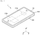
- FIG. 1 is a perspective view of a display device 1 according to an embodiment of the disclosure.
- FIG. 2 is a perspective view showing a back side of a bracket 300 of the display device 1 shown in FIG. 1 .
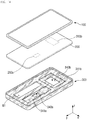
- FIG. 3 is an exploded perspective view of the display device 1 shown in FIG. 1 .
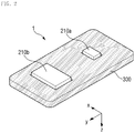
- FIG. 4 is a perspective view showing a back side of a display panel 200 shown in FIG. 3 .
- FIG. 5 is a cross-sectional view taken along line V-V' of FIG. 1 .
- FIG. 1 shows an embodiment where the display device 1 is a portable terminal.
- the portable terminal may include a tablet personal computer ("PC"), a smart phone, a personal digital assistant ("PDA”), a portable multimedia player (“PMP”), a game console, a wristwatch-type electronic device and the like.
- PC personal computer
- PDA personal digital assistant
- PMP portable multimedia player
- the disclosure is not limited thereto.
- the display device 1 may be a small and medium-sized electronic device, such as a personal computer, a notebook computer, a car navigation device and a camera, for example, as well as a large electronic apparatus such as a television (“TV”) or an external billboard, for example.
- TV television
- an external billboard for example.
- an embodiment of the display device 1 may have a rectangular-like shape (e.g., a rectangle with rounded corners) in a plan view, e.g., when viewed from a top plan view.
- the display device 1 may include two opposing short sides extending in a first direction x, and two opposing long sides extending in a second direction y.
- a corner, where the long side and the short side of the display device 1 meet each other may have a right angle, or may be curved as shown in FIG. 1 .
- the planar shape of the display device 1 is not limited to those shown in the accompanying drawings. Alternatively, the planar shape of the display device 1 may be circular or other shapes.
- the display device 1 includes a display area DA for displaying an image and a non-display area NDA adjacent to the display area DA.
- the non-display area NDA may surround the display area DA.
- the display device 1 may include a plurality of vibro-acoustic elements 210a and 210b to be described later.
- the vibro-acoustic elements 210a and 210b may be an element having a speaker function or a microphone function by being vibrated.
- the plurality of vibro-acoustic elements 210a and 210b may be disposed in the display area DA, but not being limited thereto. In an alternative embodiment, a part of the plurality of vibro-acoustic elements 210a and 210b may be disposed in the display area DA and another part thereof may be disposed in the non-display area NDA. In another alternative embodiment, all of the plurality of vibro-acoustic elements 210a and 210b may be disposed in the non-display area NDA. In another alternative embodiment, the plurality of vibro-acoustic elements 210a and 210b may be disposed over the display area DA and the non-display area NDA. The plurality of vibro-acoustic elements 210a and 210b will be described later in greater detail.
- an embodiment of the display device 1 includes the display panel 200 and the plurality of vibro-acoustic elements 210a and 210b disposed on a lower surface of the display panel 200.
- the display device 1 may further include a bracket 300 disposed below the display panel 200.
- the display device 1 may further include a window 100 disposed on the display panel 200.
- the display device 1 may further include an input sensing member (e.g., a touch panel) disposed between the display panel 200 and the window 100.
- the terms “above”, “top” and “upper” as used herein refer to a display surface side with respect to the display panel 200 (i.e., a third direction z), and the terms “below”, “bottom” and “lower” as used herein refer to an opposite side of the display surface with respect to the display panel 200 (i.e., an opposite direction to the third direction z).
- the window 100 may include a light transmitting portion 100-DA for transmitting an image displayed by the display panel 200, and a light shielding portion 100-NDA adjacent to the light transmitting portion 100-DA.
- a light transmitting portion 100-DA for transmitting an image displayed by the display panel 200
- a light shielding portion 100-NDA adjacent to the light transmitting portion 100-DA.
- an inner surface of the light shielding portion 100-NDA of the window 100 may have an opaque masking layer.
- the window 100 may be disposed above the display panel 200 to protect the display panel 200.
- the window 100 may overlap the display panel 200 and cover the entire top surface of the display panel 200.
- the window 100 may be larger than the display panel 200.
- the window 100 may have short sides extending further from the display panel 200 at both short sides of the display device 1, and long sides extending further from the display panel 200 at both long sides of the display device 1.
- a distance between corresponding short sides of the window 100 and the display panel 200 may be larger than that between corresponding long sides thereof.
- the window 100 may include or be made of glass, sapphire, plastic or the like.
- the window 100 may be rigid, but not being limited thereto. Alternatively, the window 100 may be flexible.
- the display panel 200 includes a display portion 200-DA and a non-display portion 200-NDA.
- the display portion 200-DA is an area for displaying an image, and corresponds to or overlaps the light transmitting portion 100-DA of the window 100.
- the non-display portion 200-NDA which is an area where no image is displayed, is adjacent to the display portion 200-DA, and corresponds to or overlaps the light shielding portion 100-NDA of the window 100.
- the display panel 200 may include a structure in which a driving element, such as a thin film transistor, and a display element are disposed on a base substrate including a glass, a polymer or the like.
- a driving element such as a thin film transistor
- a display element are disposed on a base substrate including a glass, a polymer or the like.
- the display panel 200 may be a display panel including a self-luminous element as a display element.
- the display panel 200 includes a display panel including an organic light emitting diode in which an organic light emitting layer is included as a light emitting layer, or a display panel including a quantum dot light emitting diode in which a quantum dot light emitting layer is included as a light emitting layer.
- the disclosure is not limited thereto.
- the display panel 200 may be implemented as a liquid crystal display panel or the like.
- the display panel 200 is a display panel including an organic light emitting diode will be described.
- the display panel 200 may include a touch electrode portion therein.
- a separate input sensing member typically disposed between the window 100 and the display panel 200, may be omitted.
- the display panel 200 may further include a lower panel member (not shown) disposed below the display panel 200.
- the lower panel member may be is a member provided for a heat dissipation function, an electromagnetic wave shielding function, a light shielding or light absorbing function, a buffering function, a digitizing function and the like, and the lower panel member may include a functional layer having at least one of the functions described above.
- the functional layer may be provided in various forms such as a layer, a film, a sheet, a plate, a panel and the like.
- the plurality of vibro-acoustic elements 210a and 210b is disposed below the display panel 200.
- the vibro-acoustic elements 210a and 210b are elements that vibrate in response to a signal including audio data, which is an electrical signal corresponding to the audio data.
- the vibro-acoustic elements 210a and 210b may include, for example, a magnet and a coil surrounding the magnet to allow a current corresponding to the acoustic signal to flow therethrough.
- the vibro-acoustic elements 210a and 210b may vibrate by an electromagnetic force corresponding to a current flowing in the coil.
- the disclosure is not limited thereto.
- the vibro-acoustic elements 210a and 210b may be piezoelectric elements including a vibration material layer.
- the vibration material layer may be mechanically deformed in response to the acoustic signal, and the vibro-acoustic elements 210a and 210b may vibrate by the mechanical deformation.
- the vibration material layer may include at least one of a piezoelectric material, polyvinylidene fluoride ("PVDF”) and an electroactive polymer, for example.
- PVDF polyvinylidene fluoride
- electroactive polymer for example.
- the vibro-acoustic elements 210a and 210b may include electrodes 211 and 213 opposite to each other, and vibration material layers 212a and 212b located therebetween.
- each of the vibro-acoustic elements 210a and 210b include a first electrode 211a or 211b disposed below the display panel 200, a vibration material layer 212a or 212b disposed below the first electrode 211a or 211b, and a second electrode 213a or 213b disposed below the vibration material layer 212a or 212b.
- the first electrodes 211a and 211b may be in contact with the lower surface of the display panel 200.
- the first electrode 211a or 211b and the second electrode 213a or 213b provide an electric field to the vibration material layer 212a or 212b.
- the first electrodes 211a and 211b and the second electrodes 213a and 213b may include or be formed of a conductive material.
- the conductive material may be a transparent conductor, such as indium tin oxide ("ITO") and indium zinc oxide (“IZO”), an opaque metal, a conducting polymer, carbon nanotubes (“CNT”s) or the like.
- the vibration material layers 212a and 212b include a piezo material that vibrates when an electric field provided by the first electrodes 211a and 211b and the second electrodes 213a and 213b is applied thereto.
- the piezoelectric material includes at least one of a piezoelectric material such as a PVDF film and a lead zirconate titanate (“PZT”) ceramic, and an electroactive polymer.
- the plurality of vibro-acoustic elements 210a and 210b is coupled to the lower surface of the display panel 200.
- the plurality of vibro-acoustic elements 210a and 210b may be disposed directly on the lower surface of the display panel 200 as shown in FIG. 4 .
- the plurality of vibro-acoustic elements 210a and 210b are attached to the lower surface of the display panel 200 through a separate adhesive member or the like provided therebetween.
- the plurality of vibro-acoustic elements 210a and 210b may be coupled to a base substrate of the display panel 200. In an embodiment, where the lower panel member is provided, the plurality of vibro-acoustic elements 210a and 210b may be coupled to the lower panel member. In such an embodiment, the plurality of vibro-acoustic elements 210a and 210b may be disposed in direct contact with the lowermost layer or surface of the display panel 200. However, the disclosure is not limited thereto. In an embodiment of the invention, the plurality of vibro-acoustic elements 210a and 210b may be directly or indirectly coupled to the display panel 200.
- the vibro-acoustic elements 210a and 210b may vibrate in response to a voltage applied thereto, and a vibration of the vibro-acoustic elements 210a and 210b may be transmitted to the display panel 200 coupled thereto such that the display panel 200 vibrates.
- at least a part of the display panel 200 may function as a diaphragm that outputs sound in response to the vibration of the vibro-acoustic elements 210a and 210b.
- the plurality of vibro-acoustic elements 210a and 210b may include, or be divided into, a first vibro-acoustic element 210a and a second vibro-acoustic element 210b.
- the first vibro-acoustic element 210a and the second vibro-acoustic element 210b may be spaced apart from each other on the lower surface of the display panel 200.
- the first and second vibro-acoustic elements 210a and 210b may be disposed side by side along a predetermined direction, e.g., the second direction y, but not being limited thereto.
- the first vibro-acoustic element 210a and the second vibro-acoustic element 210b may vibrate with different frequencies or produces audio frequencies in different frequency bands.
- the plurality of vibro-acoustic elements 210a and 210b may produce an audio frequency in a range of about 20 hertz (Hz) to about 20 kilohertz (kHz).
- the first vibro-acoustic element 210a may produce an audio frequency in a relatively high frequency band while the second vibro-acoustic element 210b may produce an audio frequency in a relatively low frequency band.
- the audio frequency of the high frequency band produced by the first vibro-acoustic element 210a may be in a range of about 2 kHz to about 20 kHz
- the audio frequency of the low frequency band produced by the second vibro-acoustic element 210b may be in a range of about 20 Hz to about 2 kHz.
- the disclosure is not limited thereto.
- the audio frequency of the high frequency band produced by the first vibro-acoustic element 210a and the audio frequency of the low frequency band produced by the second vibro-acoustic element 210b may be slightly deviated from the above ranges, and in such embodiments, the audio frequency of the high frequency band produced by the first vibro-acoustic element 210a and the audio frequency of the low frequency band produced by the second vibro-acoustic element 210b may be considered as being substantially within the above range.
- the audio frequencies produced by the first vibro-acoustic element 210a and the audio frequencies produced by the second vibratory acoustic element 210b may partially overlap each other.
- the first and second vibro-acoustic elements 210a and 210b may have different sizes from each other to produce audio frequencies in different frequency bands, respectively.
- the size of the vibro-acoustic elements 210a and 210b may mean an area thereof when viewed from a plan view in a direction opposite to the third direction z, or an overlapping area of each of the vibro-acoustic elements 210a and 210b with the display panel 200. In an embodiment, as shown in FIG.
- the size of the first vibro-acoustic element 210a is smaller than that of the second vibro-acoustic element 210b, and the first vibro-acoustic element 210a may produce an audio frequency in a higher frequency band than that of an audio frequency produced by the second vibro-acoustic element 210b.
- a plurality of vibro-acoustic elements is included in the display device for producing audio frequencies in different frequency bands, respectively, or audio frequencies in a wide frequency band, such that sounds having various or wide frequency bands may be realized by using a plurality of vibro-acoustic elements.
- the bracket 300 may be disposed below the display panel 200.
- the bracket 300 accommodates the window 100 and the display panel 200.
- the bracket 300 may include a bottom plate and sidewalls connected to edges of the bottom plate.
- the top surface of the bottom plate of the bracket 300 may face the bottom surface of the display panel 200 and the sidewalls of the bracket 300 may face the side surfaces of the display panel 200 and the window 100.
- the bracket 300 may include or be made of a synthetic resin material, a metal material, or a combination of different materials.
- a portion of the bracket 300 may be exposed outside through a side of the display device 1 to define an outer side surface of the display device 1.
- an outer housing (not shown) may be coupled to the bottom of the bracket 300.
- a plurality of receiving holes 310a and 310b may be defined in the bottom plate of the bracket 300.
- the plurality of receiving holes 310a and 310b may be formed through the bottom plate, and may be spaced apart from each other.
- the plurality of receiving holes 310a and 310b may be holes in which the plurality of vibro-acoustic elements 210a and 210b is disposed. In an embodiment, the plurality of receiving holes 310a and 310b may be defined at positions corresponding to the plurality of vibro-acoustic elements 210a and 210b, respectively. Each of the receiving holes 310a and 310b may have a size capable of accommodating the corresponding one of the vibro-acoustic elements 210a and 210b. In an embodiment, as shown in FIG.
- the display panel 200 when the display panel 200 is accommodated in the bracket 300, the first and second vibro-acoustic elements 210a and 210b are received in the first and second receiving holes 310a and 310b, respectively. Accordingly, the display panel 200 may be accommodated in the bracket 300 to minimize or substantially decrease a height difference due to the plurality of vibro-acoustic elements 210a and 210b.
- Each of the receiving holes 310a and 310b may have a different through area, which is a cross-sectional area in a direction perpendicular to the third direction z, depending on the size of the corresponding one of the vibro-acoustic elements 210a and 210b.
- the disclosure is not limited thereto.
- the bracket 300 and the plurality of vibro-acoustic elements 210a and 210b may be spaced apart from each other by a predetermined distance without being in contact with each other, such that a space is secured for vibration of the vibro-acoustic elements 210a and 210b, that is, the vibro-acoustic elements 210a and 210b is effectively prevented from contacting the bracket 300 when vibrating.
- each of the plurality of receiving holes 310a and 310b may have a larger size than that of the corresponding one of the vibro-acoustic elements 210a and 210b.
- the thickness of the plurality of vibro-acoustic elements 210a and 210b may be greater than the thickness of the bracket 300.
- the plurality of vibro-acoustic elements 210a and 210b may protrude further downward (in the opposite direction to the third direction z) than the lower surface of the bracket 300, but the disclosure is not limited thereto.
- vibration spaces 311a and 311b are defined by recessed portions of the bottom plate, which are around the receiving holes 310a and 310b and recessed in a thickness direction (opposite direction to the third direction z), i.e., from the top surface toward the bottom surface of the bottom plate.
- the vibration spaces 311a and 311b may be defined by portions of the bottom plate having a groove shape in which peripheral portions of the bottom plate defining the receiving holes 310a and 310b are recessed to have a thickness less than a thickness of other portions of the bottom plate.
- the vibration spaces 311a and 311b may be formed in the periphery of one or more of the receiving holes 310a and 310b. In an embodiment, as shown in FIG.
- a first vibration space 311a is defined in the periphery of the first receiving hole 310a
- a second vibration space 311b is defined in the periphery of the second receiving hole 310b.
- the vibration space of a vibro-acoustic element is defined by a space between the recessed portion of the bottom plate defining a receiving hole that receives the vibro-acoustic element, a portion of the display panel 200 overlapping the recessed portion in the thickness direction, and the vibro-acoustic element.
- the vibration spaces 311a and 311b may serve as a sound box for amplifying vibrations or sound waves generated from the vibro-acoustic elements 210a and 210b located in the receiving holes 310a and 310b.
- the first vibration space 311a may serve as a sound box for the first vibro-acoustic element 210a
- the second vibration space 311b may serve as a sound box for the second vibro-acoustic element 210b.
- the greater the vibration spaces 311a and 311b the greater the effect of amplifying sound waves or vibrations in the low frequency band.
- the vibration spaces 311a and 311b may serve to enhance the characteristics of the low frequency band.
- the size of the vibration spaces 311a and 311b may mean the volume of the vibration spaces 311a and 311b.
- the volume of the vibration spaces 311a and 311b may vary depending on the planar area and depth of the recessed portion of the bottom plate defining the vibration spaces 311a and 311b.
- the first vibration space 311a and the second vibration space 311b may have a same volume as each other, but the disclosure is not limited thereto.
- the vibration spaces 311a and 311b may have different volumes from each other to produce audio frequencies in various frequency bands.
- the vibro-acoustic elements 210a and 210b, the receiving holes 310a and 310b and the vibration spaces 311a and 311b therearound have a rectangular shape in a plan view, but the disclosure is not limited thereto.
- the vibro-acoustic elements 210a and 210b may have various shapes such as a polygonal shape and a curved shape in a plan view.
- the receiving holes 310a and 310b and the vibration spaces 311a and 311b may have various shapes corresponding to the shapes of the vibro-acoustic elements 210a and 210b.
- FIG. 6 is a perspective view of the display panel 200 and vibro-acoustic elements 220a, 220b and 220c of a display device according to an alternative embodiment of the disclosure.
- the display device of FIG. 6 is substantially the same as the display device described with reference to FIGS. 1 to 5 except that a plurality of vibro-acoustic elements 220a, 220b and 220c include first, second and third vibro-acoustic elements 220a, 220b and 220c.
- any repetitive detailed description of a same element will be omitted and differences will be mainly described.
- the plurality of vibro-acoustic elements 220a, 220b and 220c may include a first vibro-acoustic element 220a which produces an audio frequency of a high frequency band, a second vibro-acoustic element 220b which produces an audio frequency of a middle frequency band, and a third vibro-acoustic element 220c which produces an audio frequency of a low frequency band.
- the audio frequency of the high frequency band produced by the first vibro-acoustic element 220a may be in a range of about 2 kHz to about 20 kHz
- the audio frequency of the middle frequency band produced by the second vibro-acoustic element 220b is in a range of about 500 Hz to about 2 kHz
- the audio frequency of the low frequency band produced by the third vibro-acoustic element 220c may be in a range of about 20 Hz to about 500 Hz.
- the disclosure is not limited thereto.
- the audio frequency of the high frequency band produced by the first vibro-acoustic element 220a, the audio frequency of the middle frequency band produced by the second vibro-acoustic element 220b and the audio frequency of the low frequency band produced by the third vibro-acoustic element 220c may be slightly deviated from the above ranges, and in such embodiments, the audio frequency of the high frequency band produced by the first vibro-acoustic element 220a, the audio frequency of the middle frequency band produced by the second vibro-acoustic element 220b and the audio frequency of the low frequency band produced by the third vibro-acoustic element 220c may be considered as being substantially within the above range.
- the frequencies produced by each of the vibro-acoustic elements 220a, 220b and 220c and the frequencies produced by another one of the vibro-acoustic elements 220a, 220b and 220c may partially overlap each other.
- the frequencies produced by the first, second and third vibro-acoustic elements 220a, 220b, and 220c may have relative values to each other without being limited to specific values.
- the first vibro-acoustic element 220a produces an audio frequency of a relatively high or higher frequency band than the second vibro-acoustic element 220b
- the second vibro-acoustic element 220b produces an audio frequency of a relatively high or higher frequency band than the third vibro-acoustic element 220c
- the frequency values may not be limited to a frequency within a specific range.
- the first, second and third vibro-acoustic elements 220a, 220b and 220c may be sequentially arranged. Specifically, the first, second and third vibro-acoustic elements 220a, 220b, and 220c may be sequentially arranged on the display panel 200 along a predetermined direction, e.g., the second direction y, as shown in FIG. 6 .
- a predetermined direction e.g., the second direction y
- the disclosure is not limited thereto and the arrangement thereof may be variously changed.
- the first, second and third vibro-acoustic elements 220a, 220b, and 220c have different sizes from each other as described above, thereby producing frequencies in different frequency bands.
- the vibro-acoustic element that produced the frequency of a higher frequency band may have a smaller size. Accordingly, the first vibro-acoustic element 220a that produces an audio frequency in the highest frequency band may have the smallest size, and the third vibro-acoustic element 220c that produces an audio frequency in the lowest frequency band may have the largest size.
- the vibro-acoustic elements for outputting high, middle and low frequencies, respectively are provided, thereby effectively producing audio frequencies that cover all of high, middle and low frequency bands.
- FIG. 7 is a perspective view of a display panel 201 and vibro-acoustic elements 210a and 210b of a display device according to another alternative embodiment of the disclosure.
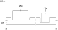
- FIG. 8 is a cross-sectional view taken along line VIII-VIII' of FIG. 7 .
- the back side of the display panel 201 is illustrated.
- the display device of FIGS. 7 and 8 is substantially the same as the display device described with reference to FIGS. 1 to 5 except that portions of the display panel 201 corresponding to the plurality of vibro-acoustic elements 210a and 210b are recessed.
- any repetitive detailed description of a same element will be omitted and differences will be mainly described.
- an embodiment of the display panel 201 may to have a shape in which portions of the display panel 201 corresponding to (or overlapping) the plurality of vibro-acoustic elements 210a and 210b are recessed in the thickness direction (opposite direction to the z direction), i.e., from the lower surface toward the upper surface of the display panel 201.
- the portions corresponding to the plurality of vibro-acoustic elements 210a and 210b may be thinner than the other portions.
- the recessed portions of the display panel 201 may be formed by partially etching the base substrate located in the lower layer of the display panel 201.
- the display panel 201 may vibrate with a greater amplitude due to the vibration provided from the vibro-acoustic elements 210a and 210b, thereby improving the sound output performance of the display device.
- the recessed depth of a portion corresponding to the first vibro-acoustic element 210a may be different from the recessed depth of a portion corresponding to the second vibro-acoustic element 210b.
- the disclosure is not limited thereto, and alternatively, the recessed depths of the portions corresponding to the vibro-acoustic elements 210a and 210b may be equal to each other.
- FIG. 9 is a perspective view of a display panel 200 and vibro-acoustic elements 210a and 210b of a display device according to another alternative embodiment of the disclosure.
- the back side of the display panel 200 is illustrated.
- the display device of FIG. 9 is substantially the same as the display device described with reference to FIGS. 1 to 5 except a vibration reinforcing member disposed between the second vibro-acoustic element 210b and the display panel 200.
- any repetitive detailed description of a same element will be omitted and differences will be mainly described.
- the display device further includes a vibration reinforcing member S disposed between the display panel 200 and the second vibro-acoustic element 210b which produces an audio frequency of a low frequency band.
- the vibration reinforcing member S may reinforce the strength of the vibration of the display panel provided from the vibro-acoustic elements 210a and 210b and allow the display panel 200 to more accurately respond to the vibration of the vibro-acoustic elements 210a and 210b.
- the vibration reinforcing member S may improve the vibration of the low frequency band provided from the second vibro-acoustic element 210b.
- the vibration reinforcing member S may include or be formed of a metal plate, a foam layer, a supporting material or reinforcing structure, or a combination thereof.
- the vibration reinforcing member S may be coupled to both the display panel 200 disposed thereon and the second vibro-acoustic element 210b disposed therebelow, thereby maintaining a state where the second vibro-acoustic element 210b is coupled to the display panel 200.
- the vibration reinforcing member S may be disposed only in the second vibro-acoustic element 210b, but the disclosure is not limited thereto. In an alternative embodiment, the vibration reinforcing member S may be disposed between the first vibro-acoustic element 210a and the display panel 200 to reinforce the output of the first vibro-acoustic element 210a.
- FIG. 10 is a perspective view of a display panel 200 and vibro-acoustic elements 230a and 210b of a display device according to still another alternative embodiment of the disclosure.
- the back side of the display panel 200 is illustrated.
- the display device of FIG. 10 is substantially the same as the display device described with reference to FIGS. 1 to 5 except that the first vibro-acoustic element 230a includes both a coil C and a piezoelectric element P.
- the first vibro-acoustic element 230a includes both a coil C and a piezoelectric element P.
- the first vibro-acoustic element 230a which produces an audio frequency of a high frequency band may include both the coil C and the piezoelectric element P. As the first vibro-acoustic element 230a includes both the coil C and the piezoelectric element P, the output of the high frequency band may be improved.
- the piezoelectric element P may be disposed on the lower surface of the display panel 200, and the coil C may be disposed on the piezoelectric element P.
- the disclosure is not limited thereto.
- the coil C may be disposed on the lower surface of the display panel 200, and the piezoelectric element P may be disposed on the coil C.
- the first vibro-acoustic element 230a includes both the coil C and the piezoelectric element P, but the disclosure is not limited thereto.
- the second vibro-acoustic element 210b may also include both a coil and a piezoelectric element.
- FIG. 11 is a perspective view of a display panel 200, vibro-acoustic elements 240a and 240b and a bracket 301 of a display device according to still another alternative embodiment of the disclosure.
- the display device of FIG. 11 is substantially the same as the display device described with reference to FIGS. 1 to 5 except that the plurality of vibro-acoustic elements 240a and 240b have the same size as each other, and the plurality of vibration spaces 321a and 321b defined in the bracket 301 have different sizes from each other.
- any repetitive detailed description of a same element will be omitted and differences will be mainly described.
- the first vibro-acoustic element 240a and the second vibro-acoustic element 240b have the same size as each other, while the first vibration space 321a and the second vibration space 321b defined in the bracket 301 may have different sizes from each other.
- the size of the first vibration space 321a corresponding to the first vibro-acoustic element 240a may be smaller than the size of the second vibration space 321b corresponding to the second vibro-acoustic element 240b.
- the sizes of the first and second vibration spaces 321a and 321b defined in the bracket 301 are different from each other, and the frequency bands of the audio frequencies produced from regions where the first and second vibro-acoustic elements 240a and 240b are disposed may become different from each other.
- the sizes of a plurality of receiving holes 320a and 320b defined in the bottom plate of the bracket 300 may be the same as each other.
- an audio frequency of a higher frequency band may be produced.
- the size of the vibro-acoustic elements 240a and 240b may be defined as an area where the vibro-acoustic elements 240a and 240b overlap the display panel 200, and the size of the vibration spaces 321a and 321b may be defined as the volume of the vibration spaces 321a and 321b.
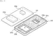
- FIG. 12 is a perspective view of a display panel 200, vibro-acoustic elements 250a and 250b and a bracket 302 of a display device according to still another embodiment of the disclosure.
- the display device of FIG. 12 is substantially the same as the display device described with reference to FIGS. 1 to 5 except that all of a plurality of vibro-acoustic elements 250a and 250b and a plurality of vibration spaces 331a and 331b have different sizes from each other.
- any repetitive detailed description of a same element will be omitted and differences will be mainly described.
- the first vibro-acoustic element 250a and the second vibro-acoustic element 250b may have different sizes from each other, and the first vibration space 331a and the second vibration space 331b defined in the bracket 302 may also have different sizes from each other.
- the sizes of a plurality of receiving holes 330a and 330b defined in the bottom plate of the bracket 300 may be different from each other.
- the sizes of the first and second vibro-acoustic elements 250a and 250b and the sizes of the first and second vibration spaces 331a and 331b are different from each other, the frequency bands of the audio frequencies produced from regions where the first and second vibro-acoustic elements 250a and 250b are disposed may become different from each other.
- the size of the vibro-acoustic elements 250a and 250b and the vibration spaces 331a and 331b is smaller, an audio frequency of a higher frequency band may be produced.
- the size of the vibro-acoustic elements 250a and 250b may mean an area where the vibro-acoustic elements 250a and 250b overlap the display panel 200, and the size of the vibration spaces 331a and 331b may mean the volume of the vibration spaces 331a and 331b.
- FIG. 13 is a perspective view showing a back side of a bracket 303 of a display device 2 according to still another alternative embodiment of the disclosure.
- FIG. 14 is an exploded perspective view of the display device 2 shown in FIG. 13 .
- FIG. 15 is a cross-sectional view taken along line XV-XV' of FIG. 13 .
- the display device 2 of FIGS. 13 to 15 is substantially the same as the display device described with reference to FIGS. 1 to 5 except that a battery receiving hole B1, in which a battery may be accommodated is defined in the bracket 303.
- a battery receiving hole B1 in which a battery may be accommodated is defined in the bracket 303.
- the battery receiving hole B1 for accommodating a battery may be further defined in the bottom plate of the bracket 303 in addition to a plurality of receiving holes 340a and 340b, in which a plurality of vibro-acoustic elements 260a and 260b are accommodated.
- the battery receiving hole B1 may be defined through the bottom plate of the bracket 303.
- the battery refers to a member that supplies power to the display device 2, and is not limited in terms of its shape, size, material or the like.
- the shape and size of the battery receiving hole B1 may correspond to the shape and size of the battery so that the battery may be effectively received therein.
- the battery receiving hole B1 may be spaced apart from the plurality of receiving holes 340a and 340b.
- the battery receiving hole B1 when viewed from a plan view, the battery receiving hole B1 may be disposed at one lower end of the bracket 303, a first receiving hole 340a may be disposed at the other lower end of the bracket 303, and a second receiving hole 340b may be disposed at an upper side of the battery receiving hole B1 and the first receiving hole 340a.
- the first vibro-acoustic element 260a having a relatively small size and which produces an audio frequency of a high frequency band and the first receiving hole 340a corresponding to the first vibro-acoustic element 260a may be arranged side by side with the battery receiving hole B1, and the second vibro-acoustic element 260b having a relatively large size and which produces an audio frequency of a low frequency band and the second receiving hole 340b corresponding to the second vibro-acoustic element 260b may be disposed in the remaining region where the battery receiving hole B1 and the first receiving hole 340a are not defined.
- the position, size and the like of the plurality of vibro-acoustic elements 260a and 260b and the receiving holes 340a and 340b may be variously modified based on the shape and size of the battery receiving hole B1.
- the vibration spaces 341a and 341b defined in the periphery of the plurality of receiving holes 340a and 340b may be spaced apart from the battery receiving hole B1. In such an embodiment, a vibration space may not be formed in the battery receiving hole B1.
- the first vibration space 341a and the second vibration space 341b may have a same size as each other, but are not limited thereto. In alternative embodiments, the size relationship between the first vibration space 341a and the second vibration space 341b may be variously modified as described above.
- FIG. 16 is a perspective view showing a back side of a bracket 304 of a display device 3 according to still another alternative embodiment of the disclosure.
- FIG. 17 is an exploded perspective view of the display device 3 shown in FIG. 16 .
- FIG. 18 is a perspective view showing a back side of a display panel 200 shown in FIG. 17 .
- FIG. 19 is a cross-sectional view taken along line XIX-XIX' of FIG. 16 .
- the display device 3 of FIGS. 16 to 19 is the same as the display device described with reference to FIGS. 13 to 15 except that it further includes a third vibro-acoustic element 260c having an opening B2 defined therein.
- a third vibro-acoustic element 260c having an opening B2 defined therein.
- the third vibro-acoustic element 260c may be further disposed on the lower surface of the display panel 200, and a third receiving hole 340c may be further defined at a position corresponding to the bracket 304.
- the third vibro-acoustic element 260c may have a rectangular frame shape with an opening B2 defined therein.
- the opening B2 may have a predetermined size and shape to accommodate the battery therein.
- the third vibro-acoustic element 260c when the display panel 200 and the bracket 304 are coupled to each other, the third vibro-acoustic element 260c may be positioned inside a rim of the third receiving hole 340c and the opening B2 of the third vibro-acoustic element 260c may serve as a battery receiving hole.
- a third vibration space 341c for amplifying the vibration of the third vibro-acoustic element 260c may be disposed in the periphery of the third receiving hole 340c of the bracket 304.
- the third vibro-acoustic element 260c has a rectangular frame shape, but the disclosure is not limited thereto.
- the third vibro-acoustic element 260c may have a polygonal or closed curve frame shape.
- the third vibro-acoustic element 260c may have a shape corresponding to a part of the above-mentioned frame shape (e.g., a shape having two parallel line segments or ' ' shape). In such an embodiment, the shape of the third vibro-acoustic element 260c is not limited as long as the battery is effectively accommodated in the opening B2.
Landscapes
- Engineering & Computer Science (AREA)
- Physics & Mathematics (AREA)
- Theoretical Computer Science (AREA)
- Signal Processing (AREA)
- General Engineering & Computer Science (AREA)
- Computer Hardware Design (AREA)
- General Physics & Mathematics (AREA)
- Acoustics & Sound (AREA)
- Multimedia (AREA)
- Human Computer Interaction (AREA)
- Manufacturing & Machinery (AREA)
- Devices For Indicating Variable Information By Combining Individual Elements (AREA)
- Nonlinear Science (AREA)
- Mathematical Physics (AREA)
- Chemical & Material Sciences (AREA)
- Crystallography & Structural Chemistry (AREA)
- Optics & Photonics (AREA)
Abstract
Description
- The disclosure relates to a display panel, a bracket and a display device including the display panel and the bracket.
- An electronic device that displays an image to a user, such as a smart phone, a digital camera, a laptop computer, a navigation system and a smart television ("TV"), may include a display device for displaying the image. The display device typically includes a display panel for generating and displaying an image, and a bracket disposed below the display panel. The bracket may accommodate elements of the display panel and the like, and may protect the elements of the display panel from heat, external impact and the like.
- In such an electronic device, a separate speaker may be provided therein to provide sound in addition the display device.
- Embodiments of the disclosure relate to a display panel to which vibro-acoustic elements are coupled.
- Embodiments of the disclosure relate to a display device including a display panel, vibro-acoustic elements are coupled the display panel, and a bracket.
- In an embodiment, a display device includes: a display panel; and a plurality of vibro-acoustic elements coupled to the display panel and spaced apart from each other on the display panel, where the plurality of vibro-acoustic elements produces audio frequencies in different frequency bands, respectively.
- In another embodiment, a bracket of a display device includes a bottom plate, where a plurality of receiving holes is defined through the bottom plate, and spaced apart from each other, and a portion of the bottom plate defining a receiving hole of the plurality of receiving holes is recessed in a thickness direction of the bottom plate, such that a vibration space is defined by the portion of the bottom plate recessed in the thickness direction.
- In another embodiment, a display device incudes: a display panel; a plurality of vibro-acoustic elements coupled to the display panel and spaced apart from each other on a lower surface of the display panel; and a bracket disposed below the display panel and including a bottom plate, where a plurality of receiving holes is defined through the bottom plate. In such an embodiment, the plurality of vibro-acoustic elements is disposed in the plurality of receiving holes, respectively, a vibration space is defined by a portion of the bottom plate defining a receiving hole of the receiving holes, which is recessed from an upper surface toward a lower surface of the bottom plate, and audio frequencies in different frequency bands, respectively, are produced from regions in which the plurality of vibro-acoustic elements is disposed
- According to embodiments of the disclosure, the display device has a sound output function by including a bracket and vibro-acoustic elements.
- The effects of the disclosure are not limited to the above-described effects and other effects which are not described herein will become apparent to those skilled in the art from the following description.
- The above and other features of the invention will become more apparent by describing in detail exemplary embodiments thereof with reference to the attached drawings, in which:
-
FIG. 1 is a perspective view of a display device according to an embodiment of the disclosure; -
FIG. 2 is a perspective view showing a back side of abracket 300 of the display device shown inFIG. 1 ; -
FIG. 3 is an exploded perspective view of thedisplay device 1 shown inFIG. 1 ; -
FIG. 4 is a perspective view showing a back side of a display panel shown inFIG. 3 ; -
FIG. 5 is a cross-sectional view taken along line V-V' ofFIG. 1 ; -
FIGS. 6 and7 are perspective views of a display panel and vibro-acoustic elements of a display device according to alternative embodiments of the disclosure; -
FIG. 8 is a cross-sectional view taken along line VIII-VIII' ofFIG. 7 ; -
FIGS. 9 and10 are perspective views of a display panel and vibro-acoustic elements of a display device according to another alternative embodiment of the disclosure; -
FIGS. 11 and12 are perspective views of a display panel, vibro-acoustic elements and a bracket of a display device according to another alternative embodiment of the disclosure; -
FIG. 13 is a perspective view showing a back side of a bracket of a display device according to still another alternative embodiment of the disclosure; -
FIG. 14 is an exploded perspective view of the display device shown inFIG. 13 ; -
FIG. 15 is a cross-sectional view taken along line XV-XV' ofFIG. 13 ; -
FIG. 16 is a perspective view showing a back side of a bracket of a display device according to still another alternative embodiment of the disclosure; -
FIG. 17 is an exploded perspective view of the display device shown inFIG. 16 ; -
FIG. 18 is a perspective view showing a back side of a display panel shown inFIG. 17 ; and -
FIG. 19 is a cross-sectional view taken along line XIX-XIX' ofFIG. 16 . - The invention now will be described more fully hereinafter with reference to the accompanying drawings, in which various embodiments are shown. This invention may, however, be embodied in many different forms, and should not be construed as limited to the embodiments set forth herein. Rather, these embodiments are provided so that this disclosure will be thorough and complete, and will fully convey the scope of the invention to those skilled in the art. Like reference numerals refer to like elements throughout.
- It will be understood that when an element or layer is referred to as being "on," "connected to" or "coupled to" another element or layer, the element or layer can be directly on, directly connected or directly coupled to another element or layer, or intervening elements or layers may be present therebetween. In contrast, when an element is referred to as being "directly on," "directly connected to" or "directly coupled to" another element or layer, there are no intervening elements or layers present. As used herein, connected may refer to elements being physically, electrically and/or fluidly connected to each other.
- It will be understood that, although the terms "first," "second," "third," etc. may be used herein to describe various elements, components, regions, layers and/or sections, these elements, components, regions, layers and/or sections should not be limited by these terms. These terms are only used to distinguish one element, component, region, layer or section from another element, component, region, layer or section. Thus, a first element, component, region, layer or section discussed below could be termed a second element, component, region, layer or section without departing from the teachings herein.
- The terminology used herein is for the purpose of describing particular embodiments only and is not intended to be limiting. As used herein, the singular forms "a," "an" and "the" are intended to include the plural forms as well, including "at least one," unless the context clearly indicates otherwise. It will be further understood that the terms "comprises," "comprising," "includes" and/or "including," when used in this specification, specify the presence of stated features, integers, operations, elements, and/or components, but do not preclude the presence or addition of one or more other features, integers, steps, operations, elements, components, and/or groups thereof. "At least one" is not to be construed as limiting "a" or "an." "Or" means "and/or." As used herein, the term "and/or" includes any and all combinations of one or more of the associated listed items.
- Spatially relative terms, such as "beneath," "below," "lower," "above," "upper" and the like, may be used herein for ease of description to describe one element or feature's relationship to another element(s) or feature(s) as illustrated in the figures. It will be understood that the spatially relative terms are intended to encompass different orientations of the device in use or operation in addition to the orientation depicted in the figures. For example, if the device in the figures is turned over, elements described as "below" or "beneath" other elements or features would then be oriented "above" the other elements or features. Thus, the exemplary term "below" can encompass both an orientation of above and below.
- "About" or "approximately" as used herein is inclusive of the stated value and means within an acceptable range of deviation for the particular value as determined by one of ordinary skill in the art, considering the measurement in question and the error associated with measurement of the particular quantity (i.e., the limitations of the measurement system).
- Unless otherwise defined, all terms (including technical and scientific terms) used herein have the same meaning as commonly understood by one of ordinary skill in the art to which this disclosure belongs. It will be further understood that terms, such as those defined in commonly used dictionaries, should be interpreted as having a meaning that is consistent with their meaning in the context of the relevant art and the present disclosure, and will not be interpreted in an idealized or overly formal sense unless expressly so defined herein.
- Exemplary embodiments are described herein with reference to cross section illustrations that are schematic illustrations of idealized embodiments. As such, variations from the shapes of the illustrations as a result, for example, of manufacturing techniques and/or tolerances, are to be expected. Thus, embodiments described herein should not be construed as limited to the particular shapes of regions as illustrated herein but are to include deviations in shapes that result, for example, from manufacturing. For example, a region illustrated or described as flat may, typically, have rough and/or nonlinear features. Moreover, sharp angles that are illustrated may be rounded. Thus, the regions illustrated in the figures are schematic in nature and their shapes are not intended to illustrate the precise shape of a region and are not intended to limit the scope of the present claims.
- Hereinafter, embodiments of the disclosure will be described with reference to the accompanying drawings.
-
FIG. 1 is a perspective view of adisplay device 1 according to an embodiment of the disclosure.FIG. 2 is a perspective view showing a back side of abracket 300 of thedisplay device 1 shown inFIG. 1 .FIG. 3 is an exploded perspective view of thedisplay device 1 shown inFIG. 1 .FIG. 4 is a perspective view showing a back side of adisplay panel 200 shown inFIG. 3 .FIG. 5 is a cross-sectional view taken along line V-V' ofFIG. 1 . -
FIG. 1 shows an embodiment where thedisplay device 1 is a portable terminal. The portable terminal may include a tablet personal computer ("PC"), a smart phone, a personal digital assistant ("PDA"), a portable multimedia player ("PMP"), a game console, a wristwatch-type electronic device and the like. However, the disclosure is not limited thereto. Alternatively, thedisplay device 1 may be a small and medium-sized electronic device, such as a personal computer, a notebook computer, a car navigation device and a camera, for example, as well as a large electronic apparatus such as a television ("TV") or an external billboard, for example. - Referring to
FIG. 1 , an embodiment of thedisplay device 1 may have a rectangular-like shape (e.g., a rectangle with rounded corners) in a plan view, e.g., when viewed from a top plan view. Thedisplay device 1 may include two opposing short sides extending in a first direction x, and two opposing long sides extending in a second direction y. In an embodiment, a corner, where the long side and the short side of thedisplay device 1 meet each other, may have a right angle, or may be curved as shown inFIG. 1 . In embodiments of the disclosure, the planar shape of thedisplay device 1 is not limited to those shown in the accompanying drawings. Alternatively, the planar shape of thedisplay device 1 may be circular or other shapes. - In an embodiment, the
display device 1 includes a display area DA for displaying an image and a non-display area NDA adjacent to the display area DA. In some embodiments, the non-display area NDA may surround the display area DA. - The
display device 1 may include a plurality of vibro-acoustic elements acoustic elements - In some embodiments, the plurality of vibro-
acoustic elements acoustic elements acoustic elements acoustic elements acoustic elements - Referring to
FIGS. 1 to 5 , an embodiment of thedisplay device 1 includes thedisplay panel 200 and the plurality of vibro-acoustic elements display panel 200. Thedisplay device 1 may further include abracket 300 disposed below thedisplay panel 200. Thedisplay device 1 may further include awindow 100 disposed on thedisplay panel 200. Although not shown in the figures, thedisplay device 1 may further include an input sensing member (e.g., a touch panel) disposed between thedisplay panel 200 and thewindow 100. - Unless defined otherwise, the terms "above", "top" and "upper" as used herein refer to a display surface side with respect to the display panel 200 (i.e., a third direction z), and the terms "below", "bottom" and "lower" as used herein refer to an opposite side of the display surface with respect to the display panel 200 (i.e., an opposite direction to the third direction z).
- The
window 100 may include a light transmitting portion 100-DA for transmitting an image displayed by thedisplay panel 200, and a light shielding portion 100-NDA adjacent to the light transmitting portion 100-DA. In some embodiments, an inner surface of the light shielding portion 100-NDA of thewindow 100 may have an opaque masking layer. - The
window 100 may be disposed above thedisplay panel 200 to protect thedisplay panel 200. Thewindow 100 may overlap thedisplay panel 200 and cover the entire top surface of thedisplay panel 200. Thewindow 100 may be larger than thedisplay panel 200. In one embodiment, for example, thewindow 100 may have short sides extending further from thedisplay panel 200 at both short sides of thedisplay device 1, and long sides extending further from thedisplay panel 200 at both long sides of thedisplay device 1. However, a distance between corresponding short sides of thewindow 100 and thedisplay panel 200 may be larger than that between corresponding long sides thereof. - The
window 100 may include or be made of glass, sapphire, plastic or the like. Thewindow 100 may be rigid, but not being limited thereto. Alternatively, thewindow 100 may be flexible. - The
display panel 200 includes a display portion 200-DA and a non-display portion 200-NDA. The display portion 200-DA is an area for displaying an image, and corresponds to or overlaps the light transmitting portion 100-DA of thewindow 100. The non-display portion 200-NDA, which is an area where no image is displayed, is adjacent to the display portion 200-DA, and corresponds to or overlaps the light shielding portion 100-NDA of thewindow 100. - The
display panel 200 may include a structure in which a driving element, such as a thin film transistor, and a display element are disposed on a base substrate including a glass, a polymer or the like. - In some embodiments, the
display panel 200 may be a display panel including a self-luminous element as a display element. In one embodiment, for example, thedisplay panel 200 includes a display panel including an organic light emitting diode in which an organic light emitting layer is included as a light emitting layer, or a display panel including a quantum dot light emitting diode in which a quantum dot light emitting layer is included as a light emitting layer. However, the disclosure is not limited thereto. According to an alternative embodiment of the disclosure, thedisplay panel 200 may be implemented as a liquid crystal display panel or the like. Hereinafter, for convenience of description, embodiments where thedisplay panel 200 is a display panel including an organic light emitting diode will be described. - In some embodiments, the
display panel 200 may include a touch electrode portion therein. In such embodiments, a separate input sensing member, typically disposed between thewindow 100 and thedisplay panel 200, may be omitted. - The
display panel 200 may further include a lower panel member (not shown) disposed below thedisplay panel 200. The lower panel member may be is a member provided for a heat dissipation function, an electromagnetic wave shielding function, a light shielding or light absorbing function, a buffering function, a digitizing function and the like, and the lower panel member may include a functional layer having at least one of the functions described above. The functional layer may be provided in various forms such as a layer, a film, a sheet, a plate, a panel and the like. - In an embodiment, the plurality of vibro-
acoustic elements display panel 200. The vibro-acoustic elements acoustic elements acoustic elements acoustic elements acoustic elements acoustic elements - In such embodiments where the vibro-
acoustic elements FIG. 5 , the vibro-acoustic elements vibration material layers acoustic elements first electrode display panel 200, avibration material layer first electrode second electrode vibration material layer first electrodes display panel 200. - The
first electrode second electrode vibration material layer first electrodes second electrodes - The
vibration material layers first electrodes second electrodes - In an embodiment, the plurality of vibro-
acoustic elements display panel 200. In such an embodiment, the plurality of vibro-acoustic elements display panel 200 as shown inFIG. 4 . In an alternative embodiment, the plurality of vibro-acoustic elements display panel 200 through a separate adhesive member or the like provided therebetween. - In an embodiment, the plurality of vibro-
acoustic elements display panel 200. In an embodiment, where the lower panel member is provided, the plurality of vibro-acoustic elements acoustic elements display panel 200. However, the disclosure is not limited thereto. In an embodiment of the invention, the plurality of vibro-acoustic elements display panel 200. - The vibro-
acoustic elements acoustic elements display panel 200 coupled thereto such that thedisplay panel 200 vibrates. In an embodiment, at least a part of thedisplay panel 200 may function as a diaphragm that outputs sound in response to the vibration of the vibro-acoustic elements - The plurality of vibro-
acoustic elements acoustic element 210a and a second vibro-acoustic element 210b. The first vibro-acoustic element 210a and the second vibro-acoustic element 210b may be spaced apart from each other on the lower surface of thedisplay panel 200. The first and second vibro-acoustic elements - The first vibro-
acoustic element 210a and the second vibro-acoustic element 210b may vibrate with different frequencies or produces audio frequencies in different frequency bands. In an embodiment, the plurality of vibro-acoustic elements acoustic element 210a may produce an audio frequency in a relatively high frequency band while the second vibro-acoustic element 210b may produce an audio frequency in a relatively low frequency band. - In some embodiments, the audio frequency of the high frequency band produced by the first vibro-
acoustic element 210a may be in a range of about 2 kHz to about 20 kHz, and the audio frequency of the low frequency band produced by the second vibro-acoustic element 210b may be in a range of about 20 Hz to about 2 kHz. However, the disclosure is not limited thereto. In some embodiment, the audio frequency of the high frequency band produced by the first vibro-acoustic element 210a and the audio frequency of the low frequency band produced by the second vibro-acoustic element 210b may be slightly deviated from the above ranges, and in such embodiments, the audio frequency of the high frequency band produced by the first vibro-acoustic element 210a and the audio frequency of the low frequency band produced by the second vibro-acoustic element 210b may be considered as being substantially within the above range. In an embodiment, the audio frequencies produced by the first vibro-acoustic element 210a and the audio frequencies produced by the second vibratoryacoustic element 210b may partially overlap each other. - The first and second vibro-
acoustic elements acoustic elements acoustic elements display panel 200. In an embodiment, as shown inFIG. 4 , the size of the first vibro-acoustic element 210a is smaller than that of the second vibro-acoustic element 210b, and the first vibro-acoustic element 210a may produce an audio frequency in a higher frequency band than that of an audio frequency produced by the second vibro-acoustic element 210b. - As described above, since the vibro-acoustic element produces sound in a specific audio frequency band depending on the size thereof, sounds of various frequency bands may not be effectively produced by using a single vibro-acoustic element. In an embodiment, a plurality of vibro-acoustic elements is included in the display device for producing audio frequencies in different frequency bands, respectively, or audio frequencies in a wide frequency band, such that sounds having various or wide frequency bands may be realized by using a plurality of vibro-acoustic elements.
- In an embodiment, as shown in
FIGS. 1-3 and5 , thebracket 300 may be disposed below thedisplay panel 200. Thebracket 300 accommodates thewindow 100 and thedisplay panel 200. Thebracket 300 may include a bottom plate and sidewalls connected to edges of the bottom plate. The top surface of the bottom plate of thebracket 300 may face the bottom surface of thedisplay panel 200 and the sidewalls of thebracket 300 may face the side surfaces of thedisplay panel 200 and thewindow 100. - In some embodiments, the
bracket 300 may include or be made of a synthetic resin material, a metal material, or a combination of different materials. - In some embodiments, a portion of the
bracket 300 may be exposed outside through a side of thedisplay device 1 to define an outer side surface of thedisplay device 1. In some embodiments, an outer housing (not shown) may be coupled to the bottom of thebracket 300. - A plurality of receiving
holes bracket 300. The plurality of receivingholes - The plurality of receiving
holes acoustic elements holes acoustic elements holes acoustic elements FIG. 5 , when thedisplay panel 200 is accommodated in thebracket 300, the first and second vibro-acoustic elements holes display panel 200 may be accommodated in thebracket 300 to minimize or substantially decrease a height difference due to the plurality of vibro-acoustic elements - Each of the receiving
holes acoustic elements - In an embodiment, the
bracket 300 and the plurality of vibro-acoustic elements acoustic elements acoustic elements bracket 300 when vibrating. In such an embodiment, each of the plurality of receivingholes acoustic elements - In an embodiment, the thickness of the plurality of vibro-
acoustic elements bracket 300. In such an embodiment, as shown inFIGS. 2 and5 , the plurality of vibro-acoustic elements bracket 300, but the disclosure is not limited thereto. - In an embodiment,
vibration spaces holes vibration spaces holes vibration spaces holes FIG. 5 , afirst vibration space 311a is defined in the periphery of thefirst receiving hole 310a, and asecond vibration space 311b is defined in the periphery of thesecond receiving hole 310b. In an embodiment, the vibration space of a vibro-acoustic element is defined by a space between the recessed portion of the bottom plate defining a receiving hole that receives the vibro-acoustic element, a portion of thedisplay panel 200 overlapping the recessed portion in the thickness direction, and the vibro-acoustic element. - The
vibration spaces acoustic elements holes first vibration space 311a may serve as a sound box for the first vibro-acoustic element 210a, and thesecond vibration space 311b may serve as a sound box for the second vibro-acoustic element 210b. In such an embodiment, the greater thevibration spaces vibration spaces - The size of the
vibration spaces vibration spaces vibration spaces vibration spaces first vibration space 311a and thesecond vibration space 311b may have a same volume as each other, but the disclosure is not limited thereto. In an alternative embodiment, thevibration spaces - In an embodiment, as shown in the figures, the vibro-
acoustic elements holes vibration spaces acoustic elements holes vibration spaces acoustic elements -
FIG. 6 is a perspective view of thedisplay panel 200 and vibro-acoustic elements FIG. 6 , the back side of thedisplay panel 200 is illustrated. The display device ofFIG. 6 is substantially the same as the display device described with reference toFIGS. 1 to 5 except that a plurality of vibro-acoustic elements acoustic elements - Referring to
FIG. 6 , in an embodiment, the plurality of vibro-acoustic elements acoustic element 220a which produces an audio frequency of a high frequency band, a second vibro-acoustic element 220b which produces an audio frequency of a middle frequency band, and a third vibro-acoustic element 220c which produces an audio frequency of a low frequency band. - In an embodiment, the audio frequency of the high frequency band produced by the first vibro-
acoustic element 220a may be in a range of about 2 kHz to about 20 kHz, the audio frequency of the middle frequency band produced by the second vibro-acoustic element 220b is in a range of about 500 Hz to about 2 kHz, and the audio frequency of the low frequency band produced by the third vibro-acoustic element 220c may be in a range of about 20 Hz to about 500 Hz. However, the disclosure is not limited thereto. In some embodiment, the audio frequency of the high frequency band produced by the first vibro-acoustic element 220a, the audio frequency of the middle frequency band produced by the second vibro-acoustic element 220b and the audio frequency of the low frequency band produced by the third vibro-acoustic element 220c may be slightly deviated from the above ranges, and in such embodiments, the audio frequency of the high frequency band produced by the first vibro-acoustic element 220a, the audio frequency of the middle frequency band produced by the second vibro-acoustic element 220b and the audio frequency of the low frequency band produced by the third vibro-acoustic element 220c may be considered as being substantially within the above range. In an embodiment, the frequencies produced by each of the vibro-acoustic elements acoustic elements - In an alternative embodiment, the frequencies produced by the first, second and third vibro-
acoustic elements acoustic element 220a produces an audio frequency of a relatively high or higher frequency band than the second vibro-acoustic element 220b, and the second vibro-acoustic element 220b produces an audio frequency of a relatively high or higher frequency band than the third vibro-acoustic element 220c, the frequency values may not be limited to a frequency within a specific range. - The first, second and third vibro-
acoustic elements acoustic elements display panel 200 along a predetermined direction, e.g., the second direction y, as shown inFIG. 6 . However, the disclosure is not limited thereto and the arrangement thereof may be variously changed. - The first, second and third vibro-
acoustic elements acoustic element 220a that produces an audio frequency in the highest frequency band may have the smallest size, and the third vibro-acoustic element 220c that produces an audio frequency in the lowest frequency band may have the largest size. - In an embodiment, as described above, the vibro-acoustic elements for outputting high, middle and low frequencies, respectively, are provided, thereby effectively producing audio frequencies that cover all of high, middle and low frequency bands.
-
FIG. 7 is a perspective view of adisplay panel 201 and vibro-acoustic elements FIG. 8 is a cross-sectional view taken along line VIII-VIII' ofFIG. 7 . InFIG. 7 , the back side of thedisplay panel 201 is illustrated. The display device ofFIGS. 7 and8 is substantially the same as the display device described with reference toFIGS. 1 to 5 except that portions of thedisplay panel 201 corresponding to the plurality of vibro-acoustic elements - Referring to
FIGS. 7 and8 , an embodiment of thedisplay panel 201 may to have a shape in which portions of thedisplay panel 201 corresponding to (or overlapping) the plurality of vibro-acoustic elements display panel 201. Thus, in such an embodiment of thedisplay panel 201, the portions corresponding to the plurality of vibro-acoustic elements display panel 201 may be formed by partially etching the base substrate located in the lower layer of thedisplay panel 201. - In such an embodiment, where the thickness of the portions corresponding to the vibro-
acoustic elements display panel 201 may vibrate with a greater amplitude due to the vibration provided from the vibro-acoustic elements - In such an embodiment, since the frequency band to be amplified may vary depending on the thickness of the
display panel 201, as shown inFIG. 8 , the recessed depth of a portion corresponding to the first vibro-acoustic element 210a may be different from the recessed depth of a portion corresponding to the second vibro-acoustic element 210b. However, the disclosure is not limited thereto, and alternatively, the recessed depths of the portions corresponding to the vibro-acoustic elements -
FIG. 9 is a perspective view of adisplay panel 200 and vibro-acoustic elements FIG. 9 , the back side of thedisplay panel 200 is illustrated. The display device ofFIG. 9 is substantially the same as the display device described with reference toFIGS. 1 to 5 except a vibration reinforcing member disposed between the second vibro-acoustic element 210b and thedisplay panel 200. For convenience of description, any repetitive detailed description of a same element will be omitted and differences will be mainly described. - Referring to
FIG. 9 , in an embodiment, the display device further includes a vibration reinforcing member S disposed between thedisplay panel 200 and the second vibro-acoustic element 210b which produces an audio frequency of a low frequency band. The vibration reinforcing member S may reinforce the strength of the vibration of the display panel provided from the vibro-acoustic elements display panel 200 to more accurately respond to the vibration of the vibro-acoustic elements acoustic element 210b. - The vibration reinforcing member S may include or be formed of a metal plate, a foam layer, a supporting material or reinforcing structure, or a combination thereof.
- The vibration reinforcing member S may be coupled to both the
display panel 200 disposed thereon and the second vibro-acoustic element 210b disposed therebelow, thereby maintaining a state where the second vibro-acoustic element 210b is coupled to thedisplay panel 200. - In an embodiment, as shown in
FIG. 9 , the vibration reinforcing member S may be disposed only in the second vibro-acoustic element 210b, but the disclosure is not limited thereto. In an alternative embodiment, the vibration reinforcing member S may be disposed between the first vibro-acoustic element 210a and thedisplay panel 200 to reinforce the output of the first vibro-acoustic element 210a. -
FIG. 10 is a perspective view of adisplay panel 200 and vibro-acoustic elements FIG. 10 , the back side of thedisplay panel 200 is illustrated. The display device ofFIG. 10 is substantially the same as the display device described with reference toFIGS. 1 to 5 except that the first vibro-acoustic element 230a includes both a coil C and a piezoelectric element P. For convenience of description, any repetitive detailed description of a same element will be omitted and differences will be mainly described. - Referring to
FIG. 10 , in an embodiment, the first vibro-acoustic element 230a which produces an audio frequency of a high frequency band may include both the coil C and the piezoelectric element P. As the first vibro-acoustic element 230a includes both the coil C and the piezoelectric element P, the output of the high frequency band may be improved. - In an embodiment, as shown in
FIG. 10 , the piezoelectric element P may be disposed on the lower surface of thedisplay panel 200, and the coil C may be disposed on the piezoelectric element P. However, the disclosure is not limited thereto. In an alternative embodiment, the coil C may be disposed on the lower surface of thedisplay panel 200, and the piezoelectric element P may be disposed on the coil C. - In an embodiment, as described above, the first vibro-
acoustic element 230a includes both the coil C and the piezoelectric element P, but the disclosure is not limited thereto. In an alternative embodiment, the second vibro-acoustic element 210b may also include both a coil and a piezoelectric element. -
FIG. 11 is a perspective view of adisplay panel 200, vibro-acoustic elements bracket 301 of a display device according to still another alternative embodiment of the disclosure. InFIG. 11 , the back side of thedisplay panel 200 and the front side of thebracket 301 are illustrated respectively. The display device ofFIG. 11 is substantially the same as the display device described with reference toFIGS. 1 to 5 except that the plurality of vibro-acoustic elements vibration spaces bracket 301 have different sizes from each other. For convenience of description, any repetitive detailed description of a same element will be omitted and differences will be mainly described. - Referring to
FIG. 11 , the first vibro-acoustic element 240a and the second vibro-acoustic element 240b have the same size as each other, while thefirst vibration space 321a and thesecond vibration space 321b defined in thebracket 301 may have different sizes from each other. In an embodiment, the size of thefirst vibration space 321a corresponding to the first vibro-acoustic element 240a may be smaller than the size of thesecond vibration space 321b corresponding to the second vibro-acoustic element 240b. - As shown in
FIG. 11 , in an embodiment, only the sizes of the first andsecond vibration spaces bracket 301 are different from each other, and the frequency bands of the audio frequencies produced from regions where the first and second vibro-acoustic elements holes bracket 300 may be the same as each other. In an embodiment, as the size of thevibration spaces - In an embodiment, as described above, the size of the vibro-
acoustic elements acoustic elements display panel 200, and the size of thevibration spaces vibration spaces -
FIG. 12 is a perspective view of adisplay panel 200, vibro-acoustic elements bracket 302 of a display device according to still another embodiment of the disclosure. InFIG. 12 , the back side of thedisplay panel 200 and the front side of thebracket 302 are illustrated respectively. The display device ofFIG. 12 is substantially the same as the display device described with reference toFIGS. 1 to 5 except that all of a plurality of vibro-acoustic elements vibration spaces - Referring to
FIG. 12 , in an embodiment, the first vibro-acoustic element 250a and the second vibro-acoustic element 250b may have different sizes from each other, and thefirst vibration space 331a and thesecond vibration space 331b defined in thebracket 302 may also have different sizes from each other. In such an embodiment, the sizes of a plurality of receivingholes bracket 300 may be different from each other. - As shown in
FIG. 12 , in an embodiment, the sizes of the first and second vibro-acoustic elements second vibration spaces acoustic elements acoustic elements vibration spaces - In an embodiment, as described above, the size of the vibro-
acoustic elements acoustic elements display panel 200, and the size of thevibration spaces vibration spaces -
FIG. 13 is a perspective view showing a back side of abracket 303 of adisplay device 2 according to still another alternative embodiment of the disclosure.FIG. 14 is an exploded perspective view of thedisplay device 2 shown inFIG. 13 .FIG. 15 is a cross-sectional view taken along line XV-XV' ofFIG. 13 . - The
display device 2 ofFIGS. 13 to 15 is substantially the same as the display device described with reference toFIGS. 1 to 5 except that a battery receiving hole B1, in which a battery may be accommodated is defined in thebracket 303. For convenience of description, any repetitive detailed description of a same element will be omitted and differences will be mainly described. - Referring to
FIGS. 13 to 15 , in an embodiment, the battery receiving hole B1 for accommodating a battery may be further defined in the bottom plate of thebracket 303 in addition to a plurality of receivingholes acoustic elements bracket 303. - The battery refers to a member that supplies power to the
display device 2, and is not limited in terms of its shape, size, material or the like. The shape and size of the battery receiving hole B1 may correspond to the shape and size of the battery so that the battery may be effectively received therein. - The battery receiving hole B1 may be spaced apart from the plurality of receiving
holes FIG. 14 , when viewed from a plan view, the battery receiving hole B1 may be disposed at one lower end of thebracket 303, afirst receiving hole 340a may be disposed at the other lower end of thebracket 303, and asecond receiving hole 340b may be disposed at an upper side of the battery receiving hole B1 and thefirst receiving hole 340a. In an embodiment, the first vibro-acoustic element 260a having a relatively small size and which produces an audio frequency of a high frequency band and thefirst receiving hole 340a corresponding to the first vibro-acoustic element 260a may be arranged side by side with the battery receiving hole B1, and the second vibro-acoustic element 260b having a relatively large size and which produces an audio frequency of a low frequency band and thesecond receiving hole 340b corresponding to the second vibro-acoustic element 260b may be disposed in the remaining region where the battery receiving hole B1 and thefirst receiving hole 340a are not defined. However, the disclosure is not limited thereto. The position, size and the like of the plurality of vibro-acoustic elements holes - In an embodiment, the
vibration spaces holes first vibration space 341a and thesecond vibration space 341b may have a same size as each other, but are not limited thereto. In alternative embodiments, the size relationship between thefirst vibration space 341a and thesecond vibration space 341b may be variously modified as described above. -
FIG. 16 is a perspective view showing a back side of abracket 304 of adisplay device 3 according to still another alternative embodiment of the disclosure.FIG. 17 is an exploded perspective view of thedisplay device 3 shown inFIG. 16 .FIG. 18 is a perspective view showing a back side of adisplay panel 200 shown inFIG. 17 .FIG. 19 is a cross-sectional view taken along line XIX-XIX' ofFIG. 16 . - The
display device 3 ofFIGS. 16 to 19 is the same as the display device described with reference toFIGS. 13 to 15 except that it further includes a third vibro-acoustic element 260c having an opening B2 defined therein. For convenience of description, any repetitive detailed description of a same element will be omitted and differences will be mainly described. - Referring to
FIGS. 16 to 19 , in an embodiment, the third vibro-acoustic element 260c may be further disposed on the lower surface of thedisplay panel 200, and athird receiving hole 340c may be further defined at a position corresponding to thebracket 304. - The third vibro-
acoustic element 260c may have a rectangular frame shape with an opening B2 defined therein. The opening B2 may have a predetermined size and shape to accommodate the battery therein. In an embodiment, as shown inFIG. 19 , when thedisplay panel 200 and thebracket 304 are coupled to each other, the third vibro-acoustic element 260c may be positioned inside a rim of thethird receiving hole 340c and the opening B2 of the third vibro-acoustic element 260c may serve as a battery receiving hole. - A
third vibration space 341c for amplifying the vibration of the third vibro-acoustic element 260c may be disposed in the periphery of thethird receiving hole 340c of thebracket 304.
In an embodiment, as described above, the third vibro-acoustic element 260c has a rectangular frame shape, but the disclosure is not limited thereto. In an alternative embodiment, the third vibro-acoustic element 260c may have a polygonal or closed curve frame shape. In another alternative embodiment, the third vibro-acoustic element 260c may have a shape corresponding to a part of the above-mentioned frame shape (e.g., a shape having two parallel line segments or '' shape). In such an embodiment, the shape of the third vibro-
acoustic element 260c is not limited as long as the battery is effectively accommodated in the opening B2.
Claims (19)
- A display device (1) comprising:a display panel (200);characterized bya plurality of vibro-acoustic elements (210a, 210b) coupled to the display panel (200)and spaced apart from each other on the display panel (200),wherein the plurality of vibro-acoustic elements (210a, 210b) produces audio frequencies in different frequency bands, respectively.
- The display device (1) of claim 1, wherein the plurality of vibro-acoustic elements (210a, 210b) includes:a first vibro-acoustic element (220a) which produces an audio frequency of a high frequency band;a second vibro-acoustic element (220b) which produces an audio frequency of a middle frequency band; anda third vibro-acoustic element (220c) which produces an audio frequency of a low frequency band.
- The display device of claim 1, wherein the plurality of vibro-acoustic elements (220a, 220b, 220c) have different sizes from each other to produces the audio frequencies in the different frequency bands, respectively.
- The display device of claim 1, wherein
portions of the display panel (200) are recessed in a thickness direction, and
the plurality of vibro-acoustic elements (210a, 210b) is disposed in the portions of the display panel (200) recessed in the thickness direction, respectively. - The display device of claim 4, wherein recessed depths of the portions of the display panel (201) recessed in the thickness direction are different from each other.
- The display device of claim 1, further comprising:a vibration reinforcing member (S) disposed between the display panel (200),wherein a vibro-acoustic element (210b) of the plurality of vibro-acoustic elements produces an audio frequency of a low frequency band, andthe vibration reinforcing member (S) is coupled to the display panel (200) and the vibro-acoustic element (210b) which produces the audio frequency of the low frequency band.
- The display device of claim 1, wherein
a vibro-acoustic element (230a) of the plurality of vibro-acoustic elements produces an audio frequency of a high frequency band, and
the vibro-acoustic element (230a) which produces the audio frequency of the high frequency band comprises:a coil (C) disposed on the display panel (200); anda piezoelectric element disposed on the coil (C). - The display device of claim 1, wherein the display panel is a diaphragm, such that at least a part of the display panel outputs sound in response to a vibration of the plurality of vibro-acoustic elements (210a, 210b, 210c).
- A bracket (300) of a display device (1) of at least one of claims 1 to 8, the bracket (301) comprising:a bottom plate,whereina plurality of receiving holes (310a, 310b) is defined through the bottom plate, and spaced apart from each other,a portion of the bottom plate defining a receiving hole of the plurality of receiving holes (310a, 310b) is recessed in a thickness direction of the bottom plate, anda vibration space (311a, 311b) is defined by the portion of the bottom plate recessed in the thickness direction.
- The bracket (300) of claim 9, wherein the plurality of receiving holes (310a, 310b) has different through areas from each other.
- The bracket of claim 9, wherein
another portion of the bottom plate defining another receiving hole of the plurality of receiving holes is recessed in the thickness direction of the bottom plate,
another vibration space is defined by the another portion of the bottom plate recessed in the thickness direction, and
the volume of on vibration space (321a) is different from the volume of the other vibration space (321b). - The bracket of claim 9, wherein the plurality of receiving holes comprises:a vibro-acoustic element receiving hole (340a, 340b) ; and a battery receiving hole (B1),wherein a portion of the bottom plate defining the vibro-acoustic element receiving hole (340a, 340b) is recessed in the thickness direction of the bottom plate, andwherein a portion of the bottom plate defining the battery receiving hole (B1) is not recessed.
- A display device of at least one of claims 1 to 8 comprising:a plurality of vibro-acoustic elements (240a, 240b) coupled to the display panel (200) and spaced apart from each other on a lower surface of the display panel (200); anda bracket (301) disposed below the display panel (200) and including a bottom plate,whereina plurality of receiving holes (320a, 320b) is defined through the bottom plate,the plurality of vibro-acoustic elements (240a, 240b) is disposed in the plurality of receiving holes (320a, 320b), respectively,a portion of the bottom plate defining a receiving hole (320a, 320b) of the plurality of receiving holes is recessed from an upper surface toward a lower surface of the bottom plate,a vibration space (321a, 321b) is defined by the portion of the bottom plate recessed from the upper surface toward the lower surface of the bottom plate, andaudio frequencies in different frequency bands, respectively, are produced from regions in which the plurality of vibro-acoustic elements (240a, 240b) is disposed.
- The display device of claim 13, wherein
at first portion of the bottom plate defining at first receiving hole (330a) of the plurality of receiving holes (330a, 330b) is recessed from the upper surface toward the lower surface of the bottom plate,
a second vibration space (331b) is defined by the another portion of the bottom plate recessed from the upper surface toward the lower surface of the bottom plate forming a second receiving hole (330b), and
the volume of a first vibration space (331a) is different form the volume of a second vibration space (331b) to produce the audio frequencies in the different frequency bands, respectively. - The display device of claim 13, wherein the plurality of vibro-acoustic elements (210a, 210b) and the bracket (300) are not in contact with each other.
- The display device of claim 13, wherein
a battery receiving hole (B1) is defined through the bottom plate, and
the battery receiving hole (B1) is spaced apart from the plurality of receiving holes (340a, 340b). - The display device of claim 16, wherein a portion of the bottom plate defining the battery receiving hole (B1) is not recessed.
- The display device of claim 13, wherein a vibro-acoustic element (260c) of the plurality of vibro-acoustic elements has a shape including at least a part of a frame shape in a plan view with an opening defined therein.
- The display device of claim 18, wherein the vibro-acoustic element (260c) has a rectangular frame shape in the plan view.
Applications Claiming Priority (1)
| Application Number | Priority Date | Filing Date | Title |
|---|---|---|---|
| KR1020170101804A KR102420554B1 (en) | 2017-08-10 | 2017-08-10 | Display panel, bracket and display device comprising the same |
Publications (2)
| Publication Number | Publication Date |
|---|---|
| EP3442243A1 true EP3442243A1 (en) | 2019-02-13 |
| EP3442243B1 EP3442243B1 (en) | 2025-02-19 |
Family
ID=63363841
Family Applications (1)
| Application Number | Title | Priority Date | Filing Date |
|---|---|---|---|
| EP18187475.1A Active EP3442243B1 (en) | 2017-08-10 | 2018-08-06 | Display panel, bracket and display device comprising the same |
Country Status (4)
| Country | Link |
|---|---|
| US (2) | US10671114B2 (en) |
| EP (1) | EP3442243B1 (en) |
| KR (1) | KR102420554B1 (en) |
| CN (1) | CN109389917B (en) |
Cited By (4)
| Publication number | Priority date | Publication date | Assignee | Title |
|---|---|---|---|---|
| US20200213699A1 (en) * | 2018-12-31 | 2020-07-02 | Lg Display Co., Ltd. | Display apparatus |
| GB2582674A (en) * | 2019-03-29 | 2020-09-30 | Lg Display Co Ltd | Display apparatus |
| GB2606946A (en) * | 2018-02-13 | 2022-11-23 | Lg Display Co Ltd | Display apparatus |
| US11930311B2 (en) | 2019-12-10 | 2024-03-12 | Sony Group Corporation | Sound output apparatus and oscillation provising mechanism |
Families Citing this family (31)
| Publication number | Priority date | Publication date | Assignee | Title |
|---|---|---|---|---|
| US10951992B2 (en) | 2018-12-31 | 2021-03-16 | Lg Display Co., Ltd. | Vibration generating device and display apparatus including the same |
| KR102689715B1 (en) * | 2018-12-31 | 2024-07-30 | 엘지디스플레이 주식회사 | Display apparatus |
| KR102771063B1 (en) * | 2018-12-31 | 2025-02-21 | 엘지디스플레이 주식회사 | Vibration generation device and display apparatus comprising the same |
| US11675438B2 (en) * | 2019-02-28 | 2023-06-13 | Samsung Display Co., Ltd. | Display device and sound providing method of the display device |
| KR102668569B1 (en) * | 2019-02-28 | 2024-05-24 | 삼성디스플레이 주식회사 | Display device and method for providing sound of the same |
| KR102608894B1 (en) * | 2019-03-11 | 2023-12-01 | 삼성디스플레이 주식회사 | Display device and method for driving the same |
| KR102668405B1 (en) * | 2019-03-15 | 2024-05-23 | 삼성디스플레이 주식회사 | Display device and method for driving the display device |
| KR102668395B1 (en) * | 2019-03-15 | 2024-05-23 | 삼성디스플레이 주식회사 | Display device |
| KR102689710B1 (en) | 2019-03-29 | 2024-07-29 | 엘지디스플레이 주식회사 | Display apparatus |
| CN112017529A (en) * | 2019-05-30 | 2020-12-01 | 京东方科技集团股份有限公司 | Display panel buffer structure, display screen module, preparation method of display panel buffer structure and terminal equipment |
| CN110351402B (en) * | 2019-06-28 | 2022-04-01 | 武汉华星光电技术有限公司 | Display module and mobile terminal |
| KR102714235B1 (en) * | 2019-07-08 | 2024-10-04 | 엘지디스플레이 주식회사 | Display apparatus |
| KR102734407B1 (en) * | 2019-07-09 | 2024-11-26 | 삼성디스플레이 주식회사 | Display device |
| KR102689725B1 (en) * | 2019-07-22 | 2024-07-29 | 엘지디스플레이 주식회사 | Display apparatus and vehicle comprising the same |
| KR102689721B1 (en) * | 2019-07-22 | 2024-07-29 | 엘지디스플레이 주식회사 | Display apparatus and vehicle comprising the same |
| KR102708562B1 (en) * | 2019-08-09 | 2024-09-23 | 삼성디스플레이 주식회사 | Display device and method for providing sound of the same |
| KR102771113B1 (en) | 2019-08-20 | 2025-02-21 | 삼성디스플레이 주식회사 | Display device |
| KR102733586B1 (en) * | 2019-09-09 | 2024-11-22 | 삼성디스플레이 주식회사 | Display device |
| CN112492065B (en) * | 2019-09-12 | 2022-11-11 | 华为技术有限公司 | Display terminal |
| KR102715358B1 (en) * | 2019-10-23 | 2024-10-08 | 엘지디스플레이 주식회사 | Display apparatus |
| KR102763470B1 (en) | 2019-12-16 | 2025-02-05 | 엘지디스플레이 주식회사 | Display apparatus |
| KR102799442B1 (en) * | 2019-12-31 | 2025-04-22 | 엘지디스플레이 주식회사 | Flexible Vibration Film And Display Having The Same |
| KR102734922B1 (en) | 2019-12-31 | 2024-11-26 | 엘지디스플레이 주식회사 | Display apparatus |
| CN113316060A (en) * | 2020-02-27 | 2021-08-27 | 北京小米移动软件有限公司 | Vibrator module and electronic equipment |
| KR102805671B1 (en) | 2020-03-31 | 2025-05-09 | 엘지디스플레이 주식회사 | Vibration generation device and display apparatus having the same |
| KR102808295B1 (en) * | 2020-07-21 | 2025-05-14 | 엘지디스플레이 주식회사 | Display apparatus |
| KR102787617B1 (en) * | 2020-10-21 | 2025-03-26 | 엘지디스플레이 주식회사 | Vibration apparatus and apparatus comprising the same |
| US12114117B2 (en) | 2020-12-09 | 2024-10-08 | Lg Display Co., Ltd. | Apparatus including vibration member to generate sound and vibration for enhancing sound characteristic and sound pressure level characteristic |
| CN114827318B (en) * | 2021-01-29 | 2025-10-03 | 北京小米移动软件有限公司 | electronic devices |
| KR20230096545A (en) * | 2021-12-23 | 2023-06-30 | 엘지디스플레이 주식회사 | Apparatus |
| CN118262608A (en) * | 2022-12-26 | 2024-06-28 | 京东方科技集团股份有限公司 | Display module and display device |
Citations (3)
| Publication number | Priority date | Publication date | Assignee | Title |
|---|---|---|---|---|
| DE19955867A1 (en) * | 1999-11-22 | 2001-06-21 | Harman Audio Electronic Sys | Flat speaker arrangement for bass reproduction |
| US20120140969A1 (en) * | 2010-12-02 | 2012-06-07 | Akiko Fujise | Piezoelectric speaker and piezoelectric speaker array |
| US20160150318A1 (en) * | 2014-11-24 | 2016-05-26 | Apple Inc. | Mechanically actuated panel acoustic system |
Family Cites Families (43)
| Publication number | Priority date | Publication date | Assignee | Title |
|---|---|---|---|---|
| US5025474A (en) * | 1987-09-29 | 1991-06-18 | Matsushita Electric Industrial Co., Ltd. | Speaker system with image projection screen |
| US5930376A (en) * | 1997-03-04 | 1999-07-27 | Compaq Computer Corporation | Multiple channel speaker system for a portable computer |
| US6519346B1 (en) * | 1998-01-16 | 2003-02-11 | Sony Corporation | Speaker apparatus and electronic apparatus having a speaker apparatus enclosed therein |
| EP1271998B1 (en) * | 2001-06-28 | 2008-04-16 | Matsushita Electric Industrial Co., Ltd. | Speaker system, mobile terminal device, and electronic device |
| JP3886391B2 (en) | 2002-02-15 | 2007-02-28 | シャープ株式会社 | CARD-TYPE DEVICE AND ELECTRONIC DEVICE HAVING THE SAME |
| GB0405475D0 (en) * | 2004-03-11 | 2004-04-21 | New Transducers Ltd | Loudspeakers |
| TW200706049A (en) * | 2005-05-12 | 2007-02-01 | Kenwood Corp | Screen speaker system |
| JP4192187B2 (en) * | 2005-05-24 | 2008-12-03 | エルジー エレクトロニクス インコーポレイティド | Portable terminal |
| CN101253804B (en) * | 2005-11-02 | 2012-11-28 | 日本电气株式会社 | Speaker, picture element protection screen, case of terminal equipment, and terminal equipment |
| KR200408511Y1 (en) * | 2005-11-24 | 2006-02-13 | 부전전자부품 주식회사 | Speaker for mobile terminal |
| JP4237748B2 (en) * | 2005-12-09 | 2009-03-11 | カシオ計算機株式会社 | Display module |
| US20070223744A1 (en) * | 2006-03-23 | 2007-09-27 | Epson Imaging Devices Corporation | Electro-optic device and electronic apparatus |
| KR20080063699A (en) | 2007-01-02 | 2008-07-07 | 엘지전자 주식회사 | Speaker system for display devices and display devices |
| JP4655243B2 (en) * | 2008-09-09 | 2011-03-23 | ソニー株式会社 | Speaker system and speaker driving method |
| KR101057105B1 (en) * | 2009-09-01 | 2011-08-17 | 주식회사 이노칩테크놀로지 | Vibration member and piezoelectric speaker using same |
| JP2012034064A (en) * | 2010-07-28 | 2012-02-16 | Kyocera Corp | Portable electronic apparatus |
| JP5084945B2 (en) * | 2011-01-07 | 2012-11-28 | シャープ株式会社 | Display device |
| US8934228B2 (en) | 2011-03-21 | 2015-01-13 | Apple Inc. | Display-based speaker structures for electronic devices |
| CN106406432A (en) | 2011-03-21 | 2017-02-15 | 苹果公司 | Electronic device with flexible display |
| JP5597583B2 (en) * | 2011-03-28 | 2014-10-01 | 太陽誘電株式会社 | Touch panel device and electronic device |
| KR101383702B1 (en) * | 2012-12-12 | 2014-04-09 | 삼성디스플레이 주식회사 | Display unit |
| KR102061748B1 (en) * | 2013-05-07 | 2020-01-03 | 삼성디스플레이 주식회사 | Display device |
| KR102025786B1 (en) * | 2013-07-04 | 2019-09-27 | 삼성디스플레이 주식회사 | Display device |
| KR102204384B1 (en) * | 2013-09-16 | 2021-01-18 | 삼성디스플레이 주식회사 | Display device |
| KR102116107B1 (en) * | 2013-12-30 | 2020-05-28 | 삼성디스플레이 주식회사 | Display device |
| JP6243771B2 (en) * | 2014-03-26 | 2017-12-06 | 京セラ株式会社 | Mobile device |
| KR102229137B1 (en) * | 2014-05-20 | 2021-03-18 | 삼성디스플레이 주식회사 | Display apparatus |
| KR102209145B1 (en) * | 2014-08-18 | 2021-01-29 | 삼성디스플레이 주식회사 | Display device |
| CN105491474A (en) * | 2014-10-07 | 2016-04-13 | 鸿富锦精密工业(深圳)有限公司 | Display device and electric device comprising same |
| JP2016184786A (en) * | 2015-03-25 | 2016-10-20 | 京セラ株式会社 | SOUND GENERATOR AND ELECTRONIC DEVICE USING THE SAME |
| CN106292856B (en) * | 2015-06-03 | 2020-04-07 | 宏碁股份有限公司 | Electronic device |
| CN105142077B (en) * | 2015-08-13 | 2017-05-31 | 深圳市韶音科技有限公司 | A kind of method and bone-conduction speaker for improving bone-conduction speaker leakage sound |
| CN108029222B (en) * | 2015-09-18 | 2020-08-28 | 东丽株式会社 | electronic equipment housing |
| US10142738B2 (en) * | 2016-03-28 | 2018-11-27 | Lg Display Co., Ltd. | Panel vibration type sound-generating display device |
| KR101704517B1 (en) * | 2016-03-28 | 2017-02-09 | 엘지디스플레이 주식회사 | Display device for generating sound by panel vibration type |
| CN207939678U (en) * | 2017-01-13 | 2018-10-02 | 哈曼国际工业有限公司 | Speaker accessory mounting bracket |
| KR102373433B1 (en) * | 2017-04-29 | 2022-03-10 | 엘지디스플레이 주식회사 | Display apparatus |
| KR101919454B1 (en) * | 2017-07-31 | 2018-11-16 | 엘지디스플레이 주식회사 | Display apparatus and computing apparatus |
| KR102405215B1 (en) * | 2017-11-06 | 2022-06-02 | 엘지디스플레이 주식회사 | Display apparatus |
| CN107979671A (en) * | 2017-11-22 | 2018-05-01 | 北京小米移动软件有限公司 | Mobile terminal |
| KR102416381B1 (en) * | 2017-12-29 | 2022-07-01 | 엘지디스플레이 주식회사 | Display apparatus |
| KR102595188B1 (en) * | 2018-01-23 | 2023-10-27 | 삼성디스플레이 주식회사 | Display device |
| KR102608137B1 (en) * | 2018-09-20 | 2023-11-29 | 엘지디스플레이 주식회사 | Display apparatus |
-
2017
- 2017-08-10 KR KR1020170101804A patent/KR102420554B1/en active Active
-
2018
- 2018-05-24 US US15/988,990 patent/US10671114B2/en active Active
- 2018-08-06 EP EP18187475.1A patent/EP3442243B1/en active Active
- 2018-08-06 CN CN201810883826.5A patent/CN109389917B/en active Active
-
2020
- 2020-05-29 US US16/888,259 patent/US11079792B2/en not_active Expired - Fee Related
Patent Citations (3)
| Publication number | Priority date | Publication date | Assignee | Title |
|---|---|---|---|---|
| DE19955867A1 (en) * | 1999-11-22 | 2001-06-21 | Harman Audio Electronic Sys | Flat speaker arrangement for bass reproduction |
| US20120140969A1 (en) * | 2010-12-02 | 2012-06-07 | Akiko Fujise | Piezoelectric speaker and piezoelectric speaker array |
| US20160150318A1 (en) * | 2014-11-24 | 2016-05-26 | Apple Inc. | Mechanically actuated panel acoustic system |
Cited By (18)
| Publication number | Priority date | Publication date | Assignee | Title |
|---|---|---|---|---|
| GB2606946A (en) * | 2018-02-13 | 2022-11-23 | Lg Display Co Ltd | Display apparatus |
| GB2606946B (en) * | 2018-02-13 | 2023-08-16 | Lg Display Co Ltd | Display apparatus |
| JP2023153985A (en) * | 2018-12-31 | 2023-10-18 | エルジー ディスプレイ カンパニー リミテッド | display device |
| US20220377445A1 (en) * | 2018-12-31 | 2022-11-24 | Lg Display Co., Ltd. | Display apparatus |
| JP7625661B2 (en) | 2018-12-31 | 2025-02-03 | エルジー ディスプレイ カンパニー リミテッド | Display device |
| US12185043B2 (en) * | 2018-12-31 | 2024-12-31 | Lg Display Co., Ltd. | Display apparatus |
| US11432061B2 (en) | 2018-12-31 | 2022-08-30 | Lg Display Co., Ltd. | Display apparatus |
| GB2580449B (en) * | 2018-12-31 | 2022-09-07 | Lg Display Co Ltd | Display apparatus |
| US20200213699A1 (en) * | 2018-12-31 | 2020-07-02 | Lg Display Co., Ltd. | Display apparatus |
| US10911852B2 (en) | 2018-12-31 | 2021-02-02 | Lg Display Co., Ltd. | Display apparatus |
| GB2580449A (en) * | 2018-12-31 | 2020-07-22 | Lg Display Co Ltd | Display apparatus |
| US11770656B2 (en) | 2019-03-29 | 2023-09-26 | Lg Display Co., Ltd. | Display apparatus |
| GB2582674A (en) * | 2019-03-29 | 2020-09-30 | Lg Display Co Ltd | Display apparatus |
| US12047743B2 (en) | 2019-03-29 | 2024-07-23 | Lg Display Co., Ltd. | Display apparatus |
| US11166108B2 (en) | 2019-03-29 | 2021-11-02 | Lg Display Co., Ltd. | Display apparatus |
| GB2582674B (en) * | 2019-03-29 | 2021-05-19 | Lg Display Co Ltd | Display apparatus |
| DE102019119519B4 (en) * | 2019-03-29 | 2025-07-17 | Lg Display Co., Ltd. | Display device |
| US11930311B2 (en) | 2019-12-10 | 2024-03-12 | Sony Group Corporation | Sound output apparatus and oscillation provising mechanism |
Also Published As
| Publication number | Publication date |
|---|---|
| KR102420554B1 (en) | 2022-07-14 |
| US20190050024A1 (en) | 2019-02-14 |
| KR20190018084A (en) | 2019-02-21 |
| EP3442243B1 (en) | 2025-02-19 |
| CN109389917A (en) | 2019-02-26 |
| CN109389917B (en) | 2022-04-01 |
| US10671114B2 (en) | 2020-06-02 |
| US11079792B2 (en) | 2021-08-03 |
| US20200293084A1 (en) | 2020-09-17 |
Similar Documents
| Publication | Publication Date | Title |
|---|---|---|
| US11079792B2 (en) | Display panel, bracket and display device including the same | |
| US10983637B2 (en) | Display device | |
| US11455038B2 (en) | Vibration structure, vibration device, and tactile sense presentation device | |
| CN110164300B (en) | display device | |
| CN111105736B (en) | Display apparatus | |
| US9398359B2 (en) | Display device | |
| US11522470B2 (en) | Display apparatus | |
| CN111625084B (en) | Display device | |
| KR102595188B1 (en) | Display device | |
| KR102795248B1 (en) | Display device including ultrasonic detection device | |
| KR20190070749A (en) | Electronic apparatus | |
| CN110544706B (en) | Force sensor module and display device including the force sensor module | |
| US20240385710A1 (en) | Sensor | |
| KR102705131B1 (en) | Display device | |
| US20240223963A1 (en) | Apparatus | |
| US20250277694A1 (en) | Vibration sensing apparatus | |
| KR102183085B1 (en) | Display device | |
| KR102186361B1 (en) | Display device | |
| CN113727236A (en) | Panel sound production device |
Legal Events
| Date | Code | Title | Description |
|---|---|---|---|
| PUAI | Public reference made under article 153(3) epc to a published international application that has entered the european phase |
Free format text: ORIGINAL CODE: 0009012 |
|
| STAA | Information on the status of an ep patent application or granted ep patent |
Free format text: STATUS: THE APPLICATION HAS BEEN PUBLISHED |
|
| AK | Designated contracting states |
Kind code of ref document: A1 Designated state(s): AL AT BE BG CH CY CZ DE DK EE ES FI FR GB GR HR HU IE IS IT LI LT LU LV MC MK MT NL NO PL PT RO RS SE SI SK SM TR |
|
| AX | Request for extension of the european patent |
Extension state: BA ME |
|
| STAA | Information on the status of an ep patent application or granted ep patent |
Free format text: STATUS: REQUEST FOR EXAMINATION WAS MADE |
|
| 17P | Request for examination filed |
Effective date: 20190812 |
|
| RBV | Designated contracting states (corrected) |
Designated state(s): AL AT BE BG CH CY CZ DE DK EE ES FI FR GB GR HR HU IE IS IT LI LT LU LV MC MK MT NL NO PL PT RO RS SE SI SK SM TR |
|
| STAA | Information on the status of an ep patent application or granted ep patent |
Free format text: STATUS: EXAMINATION IS IN PROGRESS |
|
| 17Q | First examination report despatched |
Effective date: 20210331 |
|
| P01 | Opt-out of the competence of the unified patent court (upc) registered |
Effective date: 20230516 |
|
| GRAP | Despatch of communication of intention to grant a patent |
Free format text: ORIGINAL CODE: EPIDOSNIGR1 |
|
| STAA | Information on the status of an ep patent application or granted ep patent |
Free format text: STATUS: GRANT OF PATENT IS INTENDED |
|
| INTG | Intention to grant announced |
Effective date: 20240925 |
|
| RIN1 | Information on inventor provided before grant (corrected) |
Inventor name: CHU, HYE YONG Inventor name: SONG, KEUN KYU Inventor name: NOH, JUNG HUN Inventor name: KIM, SUNG CHUL Inventor name: AHN, YI JOON |
|
| GRAS | Grant fee paid |
Free format text: ORIGINAL CODE: EPIDOSNIGR3 |
|
| GRAA | (expected) grant |
Free format text: ORIGINAL CODE: 0009210 |
|
| STAA | Information on the status of an ep patent application or granted ep patent |
Free format text: STATUS: THE PATENT HAS BEEN GRANTED |
|
| AK | Designated contracting states |
Kind code of ref document: B1 Designated state(s): AL AT BE BG CH CY CZ DE DK EE ES FI FR GB GR HR HU IE IS IT LI LT LU LV MC MK MT NL NO PL PT RO RS SE SI SK SM TR |
|
| REG | Reference to a national code |
Ref country code: GB Ref legal event code: FG4D |
|
| REG | Reference to a national code |
Ref country code: CH Ref legal event code: EP |
|
| REG | Reference to a national code |
Ref country code: DE Ref legal event code: R096 Ref document number: 602018079271 Country of ref document: DE |
|
| REG | Reference to a national code |
Ref country code: IE Ref legal event code: FG4D |
|
| REG | Reference to a national code |
Ref country code: NL Ref legal event code: FP |
|
| PG25 | Lapsed in a contracting state [announced via postgrant information from national office to epo] |
Ref country code: RS Free format text: LAPSE BECAUSE OF FAILURE TO SUBMIT A TRANSLATION OF THE DESCRIPTION OR TO PAY THE FEE WITHIN THE PRESCRIBED TIME-LIMIT Effective date: 20250519 |
|
| PG25 | Lapsed in a contracting state [announced via postgrant information from national office to epo] |
Ref country code: FI Free format text: LAPSE BECAUSE OF FAILURE TO SUBMIT A TRANSLATION OF THE DESCRIPTION OR TO PAY THE FEE WITHIN THE PRESCRIBED TIME-LIMIT Effective date: 20250219 |
|
| PG25 | Lapsed in a contracting state [announced via postgrant information from national office to epo] |
Ref country code: PL Free format text: LAPSE BECAUSE OF FAILURE TO SUBMIT A TRANSLATION OF THE DESCRIPTION OR TO PAY THE FEE WITHIN THE PRESCRIBED TIME-LIMIT Effective date: 20250219 |
|
| PG25 | Lapsed in a contracting state [announced via postgrant information from national office to epo] |
Ref country code: ES Free format text: LAPSE BECAUSE OF FAILURE TO SUBMIT A TRANSLATION OF THE DESCRIPTION OR TO PAY THE FEE WITHIN THE PRESCRIBED TIME-LIMIT Effective date: 20250219 |
|
| REG | Reference to a national code |
Ref country code: LT Ref legal event code: MG9D |
|
| PG25 | Lapsed in a contracting state [announced via postgrant information from national office to epo] |
Ref country code: IS Free format text: LAPSE BECAUSE OF FAILURE TO SUBMIT A TRANSLATION OF THE DESCRIPTION OR TO PAY THE FEE WITHIN THE PRESCRIBED TIME-LIMIT Effective date: 20250619 Ref country code: NO Free format text: LAPSE BECAUSE OF FAILURE TO SUBMIT A TRANSLATION OF THE DESCRIPTION OR TO PAY THE FEE WITHIN THE PRESCRIBED TIME-LIMIT Effective date: 20250519 |
|
| PG25 | Lapsed in a contracting state [announced via postgrant information from national office to epo] |
Ref country code: HR Free format text: LAPSE BECAUSE OF FAILURE TO SUBMIT A TRANSLATION OF THE DESCRIPTION OR TO PAY THE FEE WITHIN THE PRESCRIBED TIME-LIMIT Effective date: 20250219 |
|
| PG25 | Lapsed in a contracting state [announced via postgrant information from national office to epo] |
Ref country code: LV Free format text: LAPSE BECAUSE OF FAILURE TO SUBMIT A TRANSLATION OF THE DESCRIPTION OR TO PAY THE FEE WITHIN THE PRESCRIBED TIME-LIMIT Effective date: 20250219 Ref country code: PT Free format text: LAPSE BECAUSE OF FAILURE TO SUBMIT A TRANSLATION OF THE DESCRIPTION OR TO PAY THE FEE WITHIN THE PRESCRIBED TIME-LIMIT Effective date: 20250620 |
|
| PG25 | Lapsed in a contracting state [announced via postgrant information from national office to epo] |
Ref country code: BG Free format text: LAPSE BECAUSE OF FAILURE TO SUBMIT A TRANSLATION OF THE DESCRIPTION OR TO PAY THE FEE WITHIN THE PRESCRIBED TIME-LIMIT Effective date: 20250219 Ref country code: GR Free format text: LAPSE BECAUSE OF FAILURE TO SUBMIT A TRANSLATION OF THE DESCRIPTION OR TO PAY THE FEE WITHIN THE PRESCRIBED TIME-LIMIT Effective date: 20250520 |
|
| REG | Reference to a national code |
Ref country code: AT Ref legal event code: MK05 Ref document number: 1769520 Country of ref document: AT Kind code of ref document: T Effective date: 20250219 |
|
| PGFP | Annual fee paid to national office [announced via postgrant information from national office to epo] |
Ref country code: NL Payment date: 20250722 Year of fee payment: 8 |
|
| PG25 | Lapsed in a contracting state [announced via postgrant information from national office to epo] |
Ref country code: SE Free format text: LAPSE BECAUSE OF FAILURE TO SUBMIT A TRANSLATION OF THE DESCRIPTION OR TO PAY THE FEE WITHIN THE PRESCRIBED TIME-LIMIT Effective date: 20250219 |
|
| PG25 | Lapsed in a contracting state [announced via postgrant information from national office to epo] |
Ref country code: SM Free format text: LAPSE BECAUSE OF FAILURE TO SUBMIT A TRANSLATION OF THE DESCRIPTION OR TO PAY THE FEE WITHIN THE PRESCRIBED TIME-LIMIT Effective date: 20250219 |
|
| PG25 | Lapsed in a contracting state [announced via postgrant information from national office to epo] |
Ref country code: DK Free format text: LAPSE BECAUSE OF FAILURE TO SUBMIT A TRANSLATION OF THE DESCRIPTION OR TO PAY THE FEE WITHIN THE PRESCRIBED TIME-LIMIT Effective date: 20250219 |
|
| PGFP | Annual fee paid to national office [announced via postgrant information from national office to epo] |
Ref country code: DE Payment date: 20250721 Year of fee payment: 8 |
|
| PG25 | Lapsed in a contracting state [announced via postgrant information from national office to epo] |
Ref country code: IT Free format text: LAPSE BECAUSE OF FAILURE TO SUBMIT A TRANSLATION OF THE DESCRIPTION OR TO PAY THE FEE WITHIN THE PRESCRIBED TIME-LIMIT Effective date: 20250219 |
|
| PGFP | Annual fee paid to national office [announced via postgrant information from national office to epo] |
Ref country code: GB Payment date: 20250722 Year of fee payment: 8 |
|
| PG25 | Lapsed in a contracting state [announced via postgrant information from national office to epo] |
Ref country code: AT Free format text: LAPSE BECAUSE OF FAILURE TO SUBMIT A TRANSLATION OF THE DESCRIPTION OR TO PAY THE FEE WITHIN THE PRESCRIBED TIME-LIMIT Effective date: 20250219 |
|
| PGFP | Annual fee paid to national office [announced via postgrant information from national office to epo] |
Ref country code: FR Payment date: 20250725 Year of fee payment: 8 |
|
| PG25 | Lapsed in a contracting state [announced via postgrant information from national office to epo] |
Ref country code: EE Free format text: LAPSE BECAUSE OF FAILURE TO SUBMIT A TRANSLATION OF THE DESCRIPTION OR TO PAY THE FEE WITHIN THE PRESCRIBED TIME-LIMIT Effective date: 20250219 Ref country code: CZ Free format text: LAPSE BECAUSE OF FAILURE TO SUBMIT A TRANSLATION OF THE DESCRIPTION OR TO PAY THE FEE WITHIN THE PRESCRIBED TIME-LIMIT Effective date: 20250219 |
|
| PG25 | Lapsed in a contracting state [announced via postgrant information from national office to epo] |
Ref country code: RO Free format text: LAPSE BECAUSE OF FAILURE TO SUBMIT A TRANSLATION OF THE DESCRIPTION OR TO PAY THE FEE WITHIN THE PRESCRIBED TIME-LIMIT Effective date: 20250219 |
|
| PG25 | Lapsed in a contracting state [announced via postgrant information from national office to epo] |
Ref country code: SK Free format text: LAPSE BECAUSE OF FAILURE TO SUBMIT A TRANSLATION OF THE DESCRIPTION OR TO PAY THE FEE WITHIN THE PRESCRIBED TIME-LIMIT Effective date: 20250219 |
|
| REG | Reference to a national code |
Ref country code: DE Ref legal event code: R097 Ref document number: 602018079271 Country of ref document: DE |
|
| PLBE | No opposition filed within time limit |
Free format text: ORIGINAL CODE: 0009261 |
|
| STAA | Information on the status of an ep patent application or granted ep patent |
Free format text: STATUS: NO OPPOSITION FILED WITHIN TIME LIMIT |
|
| REG | Reference to a national code |
Ref country code: CH Ref legal event code: L10 Free format text: ST27 STATUS EVENT CODE: U-0-0-L10-L00 (AS PROVIDED BY THE NATIONAL OFFICE) Effective date: 20251231 |
|
| 26N | No opposition filed |
Effective date: 20251120 |
|
| REG | Reference to a national code |
Ref country code: CH Ref legal event code: H13 Free format text: ST27 STATUS EVENT CODE: U-0-0-H10-H13 (AS PROVIDED BY THE NATIONAL OFFICE) Effective date: 20260324 |
|
| PG25 | Lapsed in a contracting state [announced via postgrant information from national office to epo] |
Ref country code: MC Free format text: LAPSE BECAUSE OF FAILURE TO SUBMIT A TRANSLATION OF THE DESCRIPTION OR TO PAY THE FEE WITHIN THE PRESCRIBED TIME-LIMIT Effective date: 20250219 |
|
| PG25 | Lapsed in a contracting state [announced via postgrant information from national office to epo] |
Ref country code: LU Free format text: LAPSE BECAUSE OF NON-PAYMENT OF DUE FEES Effective date: 20250806 |
|
| PG25 | Lapsed in a contracting state [announced via postgrant information from national office to epo] |
Ref country code: CH Free format text: LAPSE BECAUSE OF NON-PAYMENT OF DUE FEES Effective date: 20250831 |