EP3441693A1 - Air conditioner - Google Patents
Air conditioner Download PDFInfo
- Publication number
- EP3441693A1 EP3441693A1 EP17890848.9A EP17890848A EP3441693A1 EP 3441693 A1 EP3441693 A1 EP 3441693A1 EP 17890848 A EP17890848 A EP 17890848A EP 3441693 A1 EP3441693 A1 EP 3441693A1
- Authority
- EP
- European Patent Office
- Prior art keywords
- electrical
- lid
- component box
- air conditioner
- box body
- Prior art date
- Legal status (The legal status is an assumption and is not a legal conclusion. Google has not performed a legal analysis and makes no representation as to the accuracy of the status listed.)
- Granted
Links
- 238000009434 installation Methods 0.000 claims abstract description 12
- 238000005452 bending Methods 0.000 claims description 6
- 238000012423 maintenance Methods 0.000 description 32
- 239000002537 cosmetic Substances 0.000 description 4
- 230000000694 effects Effects 0.000 description 4
- 239000002184 metal Substances 0.000 description 4
- 238000010586 diagram Methods 0.000 description 2
- 238000001816 cooling Methods 0.000 description 1
- 238000010981 drying operation Methods 0.000 description 1
- 238000010438 heat treatment Methods 0.000 description 1
- 239000000463 material Substances 0.000 description 1
- 238000000034 method Methods 0.000 description 1
- 230000002265 prevention Effects 0.000 description 1
- 238000005057 refrigeration Methods 0.000 description 1
Images


Classifications
-
- F—MECHANICAL ENGINEERING; LIGHTING; HEATING; WEAPONS; BLASTING
- F24—HEATING; RANGES; VENTILATING
- F24F—AIR-CONDITIONING; AIR-HUMIDIFICATION; VENTILATION; USE OF AIR CURRENTS FOR SCREENING
- F24F1/00—Room units for air-conditioning, e.g. separate or self-contained units or units receiving primary air from a central station
- F24F1/0007—Indoor units, e.g. fan coil units
-
- F—MECHANICAL ENGINEERING; LIGHTING; HEATING; WEAPONS; BLASTING
- F24—HEATING; RANGES; VENTILATING
- F24F—AIR-CONDITIONING; AIR-HUMIDIFICATION; VENTILATION; USE OF AIR CURRENTS FOR SCREENING
- F24F11/00—Control or safety arrangements
- F24F11/89—Arrangement or mounting of control or safety devices
-
- F—MECHANICAL ENGINEERING; LIGHTING; HEATING; WEAPONS; BLASTING
- F24—HEATING; RANGES; VENTILATING
- F24F—AIR-CONDITIONING; AIR-HUMIDIFICATION; VENTILATION; USE OF AIR CURRENTS FOR SCREENING
- F24F1/00—Room units for air-conditioning, e.g. separate or self-contained units or units receiving primary air from a central station
- F24F1/0007—Indoor units, e.g. fan coil units
- F24F1/0043—Indoor units, e.g. fan coil units characterised by mounting arrangements
- F24F1/0047—Indoor units, e.g. fan coil units characterised by mounting arrangements mounted in the ceiling or at the ceiling
-
- F—MECHANICAL ENGINEERING; LIGHTING; HEATING; WEAPONS; BLASTING
- F24—HEATING; RANGES; VENTILATING
- F24F—AIR-CONDITIONING; AIR-HUMIDIFICATION; VENTILATION; USE OF AIR CURRENTS FOR SCREENING
- F24F13/00—Details common to, or for air-conditioning, air-humidification, ventilation or use of air currents for screening
- F24F13/20—Casings or covers
-
- F—MECHANICAL ENGINEERING; LIGHTING; HEATING; WEAPONS; BLASTING
- F24—HEATING; RANGES; VENTILATING
- F24F—AIR-CONDITIONING; AIR-HUMIDIFICATION; VENTILATION; USE OF AIR CURRENTS FOR SCREENING
- F24F13/00—Details common to, or for air-conditioning, air-humidification, ventilation or use of air currents for screening
- F24F13/32—Supports for air-conditioning, air-humidification or ventilation units
-
- F—MECHANICAL ENGINEERING; LIGHTING; HEATING; WEAPONS; BLASTING
- F24—HEATING; RANGES; VENTILATING
- F24F—AIR-CONDITIONING; AIR-HUMIDIFICATION; VENTILATION; USE OF AIR CURRENTS FOR SCREENING
- F24F13/00—Details common to, or for air-conditioning, air-humidification, ventilation or use of air currents for screening
- F24F13/20—Casings or covers
- F24F2013/205—Mounting a ventilator fan therein
Definitions
- the present invention relates to a ceiling-mounted air conditioner provided with an electrical-component box.
- an indoor device of the air conditioner is mounted in the ceiling.
- Patent Literature 1 discloses an air conditioner in which it is possible to suspend a lid of an electrical-component box from an electrical-component box body or an air conditioner body.
- Patent Literature 2 also discloses an air conditioner in which it is possible to suspend a lid from the electrical-component box body to temporarily hold the lid.
- the present invention has been achieved to solve the above problems, and an object of the present invention is to provide an air conditioner that can facilitate maintenance on electrical components in an electrical-component box.
- the present invention provides an air conditioner including an electrical-component box to accommodate therein electrical components on a lower surface of the air conditioner in an installation state in which the air conditioner is installed in a ceiling.
- the electrical-component box includes an electrical-component box body having a box shape with a lower surface opened in the installation state, and including a body-side engaging portion protruding outward from a side surface, and a plate-like lid capable of closing the opening and including a lid-side engaging portion to be engaged with the body-side engaging portion.
- the lid is capable of being suspended from the electrical-component box body by engaging the lid-side engaging portion with the body-side engaging portion, and the lid includes a temporary item-placement portion on which items can be temporarily placed in a suspended state in which the lid is suspended from the electrical-component box body.
- the ceiling-mounted air conditioner according to the present invention has an effect where it is possible to facilitate maintenance on electrical components in an electrical-component box.
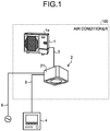
- FIG. 1 is a diagram schematically illustrating an air conditioner 100 according to a first embodiment of the present invention.
- the air conditioner 100 includes a ceiling-mounted indoor device 2, an outdoor device 1 connected to the indoor device 2 through an indoor-outdoor line 3, a wired remote controller 4 connected to the indoor device 2 through a wired remote-control line 5 that is a signal line through which a signal is transmitted.
- the indoor-outdoor line 3 includes a signal line through which a signal is transmitted between the indoor device 2 and the outdoor device 1.
- Information to be transmitted and received between the wired remote controller 4 and the indoor device 2 is transmitted to the wired remote-control line 5.
- the outdoor device 1 is provided with a cuboid-shaped outer panel 1a that is an outside casing of the outdoor device 1, a compressor, a heat exchanger, and a blower driven by a fan motor.
- FIG. 1 omits illustrations of the compressor, the heat exchanger, the fan motor, and the blower of the outdoor device 1.
- FIG. 2 is a perspective view of a casing 21 of the indoor device 2 with a lid of an electrical-component box 25 closed, as viewed from the lower side of the casing 21 in the air conditioner 100 according to the first embodiment of the present invention.
- FIG. 3 is a perspective view of the casing 21 of the indoor device 2 with the lid of the electrical-component box 25 suspended from this electrical-component box 25, as viewed from the lower side of the casing 21 in the air conditioner 100 according to the first embodiment of the present invention.
- FIGS. 2 and 3 illustrate a state in which a cosmetic panel that covers the bottom surface of the casing 21 has been removed in the air conditioner 100.
- the indoor device 2 includes the casing 21 formed by bending a sheet material into a cuboid shape, and the cosmetic panel (not illustrated) attached to the lower surface of the casing 21.
- the indoor device 2 is illustrated with its cosmetic panel removed.
- the lower surface of the casing 21 is opposed to the floor in the room in an installation state of the indoor device 2 in which the indoor device 2 is installed in the ceiling.
- the casing 21 is fixed to the ceiling wall with fixing bolts (not illustrated).
- the casing 21 includes a blower 22 located at the center inside the casing 21 and driven by a fan motor, a bell mouth 23 located at the center inside the casing 21, a plurality of outlet ports 24, the electrical-component box 25 located between the bell mouth 23 and one of the outlet ports 24, and the heat exchanger located so as to cover the blower 22.
- FIG. 2 omits illustrations of the fan motor and the heat exchanger located in the indoor device 2.
- the fan motor of the indoor device 2 is supplied with power through a power-supply line 6.
- a refrigeration cycle is constituted of the heat exchanger of the indoor device 2, the compressor of the outdoor device 1, and the heat exchanger of the outdoor device 1.
- airflow generated by the rotation of the blower 22 passes through the heat exchanger of the indoor device 2, and is then turned to cool air or warm air.
- the cool air or the warm air is discharged from the outlet ports 24 to cool or heat the room.
- the heat exchanger of the indoor device 2 functions as an evaporator.
- the heat exchanger of the indoor device 2 functions as a condenser.
- the electrical-component box 25 is constituted of an electrical-component box body 30 that is a box body made of metal sheet and having an elongated cuboid shape, and a lid 40 made of metal sheet and having an elongated rectangular plate-like shape.
- the electrical-component box body 30 is fixed to the lower surface of the casing 21.
- the lid 40 serves as the bottom surface of the electrical-component box 25 in the installation state, in which the lid 40 is capable of covering and thus closing an opening 30h formed in the electrical-component box body 30.
- the opening 30h is described later.
- FIG. 4 is a perspective view illustrating a shape of the electrical-component box body 30 of the electrical-component box 25 according to the first embodiment of the present invention.
- FIG. 4 illustrates the electrical-component box body 30 which is turned upside down compared to the state in which the electrical-component box 25 is fixed to the lower surface of the casing 21.
- the electrical-component box body 30 is configured by including a top plate 30a that constitutes the top portion of the electrical-component box body 30 in the installation state, and that has an elongated substantially-rectangular shape, and side plates 30b, 30c, 30d, 30e, 30f, and 30g that are the side surfaces extending from the edges of the top plate 30a.
- the opening 30h is formed opposed to the top plate 30a.
- the edges of the opening 30h are defined by the respective lower end portions of the side plates 30b, 30c, 30d, 30e, 30f, and 30g. That is, the electrical-component box body 30 has a box shape with its bottom surface opened in the installation state of the indoor device 2 in which the indoor device 2 is installed in the ceiling.
- two body-side engaging tabs 31 that are the body-side engaging portions are provided in a state of extending outward from the electrical-component box body 30 and parallel to the top plate 30a.
- the body-side engaging tabs 31 are formed integrally with the side plate 30b by means of sheet-metal processing. That is, the body-side engaging tabs 31 are provided in a state of protruding outward from the side surface of the electrical-component box body 30.
- the body-side engaging tabs 31 are the body-side engaging portions used for attaching the lid 40 to the electrical-component box body 30.
- Each of the body-side engaging tabs 31 also functions as the body-side engaging portion that engages with a lid-side engaging hole 43 in a removable manner in order to suspend the lid 40 from the electrical-component box body 30.
- the lid-side engaging hole 43 is described later.
- two body-side screwing tabs 32 are provided on the side plate 30e which is a side plate extending from the longer-side edge of the top plate 30a.
- the body-side screwing tabs 32 are formed integrally with the side plate 30e by means of sheet-metal processing.
- a through hole 32a used for screwing with a screw 51 is provided at the central portion of the body-side screwing tab 32 having a rectangular shape in plan view. The screw 51 is described later.
- electrical components are accommodated, such as various types of actuators and sensors used for controlling the air conditioner 100, and an electrical circuit board connected to the wired remote controller 4.
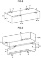
- FIG. 5 is a perspective view illustrating the shape of the lid 40 of the electrical-component box 25 according to the first embodiment of the present invention.
- FIG. 6 is a cross-sectional view of the lid 40 of the electrical-component box 25 according to the first embodiment of the present invention, which is taken along the VI-VI line in FIG. 5 .
- FIG. 7 is a cross-sectional view of the lid 40 of the electrical-component box 25 according to the first embodiment of the present invention, which is taken along the VII-VII line in FIG. 5 .
- the lid 40 is configured by including a plate-like flat portion 40a having a rectangular shape in plan view, lid-side screwing tabs 41, a bent edge portion 42, the lid-side engaging holes 43, and a cut and raised portion 44.
- the lid-side screwing tabs 41 are provided on one of the longer sides of the flat portion 40a in a state of extending outward from the flat portion 40a.
- the lid-side screwing tabs 41 are welded integrally with the flat portion 40a.
- a through hole 41a that is a keyhole used for screwing with the screw 51 is provided by means of stamping at the central portion of the lid-side screwing tab 41 having a rectangular shape in plan view. The screw 51 is described later.
- the bent edge portion 42 is formed by bending one of the longer-side edges of the flat portion 40a into an L-shape in cross section. That is, the bent edge portion 42 is formed by bending one of the longer-side edges of the flat portion 40a at a right angle toward the interior side of the electrical-component box body 30 with respect to the flat portion 40a, and thereafter bending the distal-end part of the bent part at a right angle toward the inner side of the flat portion 40a. Therefore, the bent edge portion 42 is formed by a total of 180-degree bend from the flat portion 40a. In this manner, one of the longer-side edges of the flat portion 40a, and the bent edge portion 42 form a U-shape in cross section.
- the bent edge portion 42 is located at the lower end portion of the lid 40 in a suspended state in which the lid 40 is suspended from the electrical-component box body 30 as described later. It is thus possible to use the bent edge portion 42 as a temporary item-placement portion on which necessary items for maintenance work including screws and other components can be temporarily placed at a location close to the worker.
- the bent edge portion 42 includes a surface extending perpendicularly to the flat portion 40a, on which items are placed.
- the bent edge portion 42 also includes a surface extending parallel to the flat portion 40a, which prevents the items from dropping.
- the interior side of the electrical-component box body 30 refers to the side where the top plate 30a of the electrical-component box body 30 is located when the lid 40 is attached thereto. That is, the bent edge portion 42 is provided on one surface of the flat portion 40a, which faces the interior side of the electrical-component box body 30 when the lid 40 is attached thereto as described later.
- the bent edge portion 42 is bent upward in the vertical direction in a state in which the lid 40 is suspended from the electrical-component box body 30 as described later. That is, the distal-end portion of the bent edge portion 42 is directed upward in the vertical direction in a state in which the lid 40 is suspended from the electrical-component box body 30 as described later.
- the lid-side engaging holes 43 are the lid-side engaging portions used for attaching the lid 40 to the electrical-component box body 30, and are formed by stamping in an area of the other longer-side edge of the flat portion 40a.
- the lid-side engaging holes 43 are formed with such a shape as to be engageable with the body-side engaging tabs 31 of the electrical-component box body 30.
- the lid-side engaging holes 43 engage respectively with the body-side engaging tabs 31 in a removable manner.
- Each of the lid-side engaging holes 43 also functions as the lid-side engaging portion that engages with the body-side engaging tab 31 in a removable manner when the lid 40 is suspended from the electrical-component box body 30.
- the cut and raised portion 44 is a protruding portion that protrudes obliquely upward from the flat portion 40a in a suspended state in which the lid 40 is suspended from the electrical-component box body 30.
- the area of the flat portion 40a on one-end side in the longitudinal direction is partially cut and raised, such that the cut and raised portion 44 protrudes from the flat portion 40a.
- the cut and raised portion 44 is provided on one surface of the flat portion 40a, which faces the interior side of the electrical-component box body 30. Therefore, the cut and raised portion 44 protrudes from a surface of the flat portion 40a on which the bent edge portion 42 is provided.
- the raised end portion of the cut and raised portion 44 which is raised from the flat portion 40a, is directed obliquely upward in a suspended state in which the lid 40 is suspended from the electrical-component box body 30 as described later. This makes it possible to use the cut and raised portion 44 as a temporary item-placement portion on which necessary items for maintenance work such as a bag, or cables and the like can be hooked and temporarily placed.
- FIG. 8 is a perspective view illustrating a state in which the electrical-component box body 30 according to the first embodiment of the present invention is closed with the lid 40.
- the opening 30h of the electrical-component box body 30 is closed with the lid 40 as illustrated in FIGS. 2 and 8 from the viewpoint of prevention of the spread of fire, and noise countermeasures.
- the lid 40 is fixed to the electrical-component box body 30 by inserting the body-side engaging tabs 31 of the electrical-component box body 30 through the lid-side engaging holes 43 of the lid 40 to be engaged with each other, and fastening the body-side screwing tabs 32 of the electrical-component box body 30, and the lid-side screwing tabs 41 of the lid 40 with the screws 51 inserted through the through holes 32a on the body-side screwing tabs 32, and the through holes 41a on the lid-side screwing tabs 41.
- FIG. 9 is a perspective view illustrating a state in which the lid 40 is suspended from the electrical-component box body 30 according to the first embodiment of the present invention.
- the side surfaces of the electrical-component box body 30 that are the side plates 30b, 30c, 30d, 30e, 30f, and 30g are oriented parallel to the vertical direction.
- the body-side engaging tabs 31 of the electrical-component box body 30 are oriented parallel to the horizontal direction.
- the lid-side screwing tabs 41 are directed upward in the vertical direction, while the flat portion 40a is oriented parallel to the vertical direction, the body-side engaging tabs 31 of the electrical-component box body 30 are inserted through the lid-side engaging holes 43 of the lid 40 to be engaged with each other. In this manner, the lid 40 can be suspended from the electrical-component box body 30 as illustrated in FIGS. 2 and 9 .
- the body-side engaging tabs 31 of the electrical-component box body 30 are respectively inserted through the lid-side engaging holes 43 of the lid 40 to be engaged with each other.
- the body-side screwing tabs 32 of the electrical-component box body 30, and the lid-side screwing tabs 41 of the lid 40 are not screwed with each other.
- the lid 40 can be suspended from the electrical-component box body 30 as illustrated in FIGS. 2 and 9 . In this state, the worker performs maintenance work on the electrical components.
- the lid 40 is suspended from the electrical-component box body 30 as illustrated in FIG. 9 , and thus one of the longer-side edges of the flat portion 40a, and the bent edge portion 42 form a U-shape in cross section with its upper part opened at the lower end portion of the lid 40. Therefore, in the indoor device 2, it is possible to temporarily place the removed screws 51 on the bent edge portion 42.
- the worker can use his hands more freely as compared to the case where the worker performs maintenance work with the screws 51 held in his hand. This facilitates the maintenance work and thus improves the work efficiency.
- the worker can reduce the number of times of stepping on/off the stepladder as compared to the case where the worker performs maintenance work with the screws 51 temporarily placed on the floor or somewhere else. This facilitates the maintenance work and thus improves the work efficiency.
- a worker performs maintenance work on the electrical components on a stepladder, including on-off switching and attachment of the cables and the like.
- the lid 40 is suspended from the electrical-component box body 30 as illustrated in FIG. 9 .
- a worker By hooking a bag with smaller items such as replacement components stored therein on the cut and raised portion 44, a worker can proceed with maintenance work without the need to step on/off the stepladder frequently to pick up the replacement components. This facilitates the maintenance work and thus improves the work efficiency.
- use of the electrical-component box 25 according to the present embodiment facilitates maintenance work on the electrical components accommodated in the electrical-component box 25. This improves the work efficiency.
- the bent edge portion 42 is more preferable because it is usually accommodated inside the electrical-component box body 30, and thus does not come into contact with members outside the electrical-component box 25.
- the cut and raised portion 44 protrudes from the flat portion 40a toward the exterior side of the electrical-component box body 30.
- the bent edge portion 42 is more preferable because it is usually accommodated inside the electrical-component box body 30, and thus does not come into contact with members outside the electrical-component box 25.
- the ceiling-mounted air conditioner 100 has been explained.
- the electrical-component box 25 described above is applied to a ceiling-suspended air conditioner, maintenance-work efficiency can be also improved similarly to the ceiling-mounted air conditioner 100 described above. Therefore, in an air conditioner with an indoor device installed on the ceiling, the electrical-component box 25 is installed on the lower surface of the indoor device, and thereby the air conditioner can also obtain the effects described above.
- the air conditioner 100 at the time of performing maintenance on the electrical components in the electrical-component box 25, smaller items such as the screws 51 can be temporarily placed on the bent edge portion 42 provided at the lower end portion of the lid 40 in a suspended state in which the lid 40 is suspended from the electrical-component box body 30. Due to this structure in the air conditioner 100, a worker does not need to significantly change his posture during maintenance work. This facilitates the maintenance work and can improve the work efficiency.
- the air conditioner 100 at the time of performing maintenance on the electrical components in the electrical-component box 25, work tools or components such as a bag, or cables and the like can be temporarily placed on the cut and raised portion 44 of the flat portion 40a of the lid 40 in a suspended state in which the lid 40 is suspended from the electrical-component box body 30. Due to this structure in the air conditioner 100, smaller items such as replacement components can be stored in a bag hooked on the cut and raised portion 44, and a worker can pick up the replacement components without the need to step on/off the stepladder. This facilitates the maintenance work and improves the work efficiency. Further, the worker can perform maintenance work with cables and the like kept within his sight, and therefore does not need to look for the cables and the like when necessary. This facilitates the maintenance work and improves the work efficiency.
- the air conditioner 100 according to the first embodiment has an effect where it is possible to facilitate maintenance on electrical components in the electrical-component box 25.
Abstract
Description
- The present invention relates to a ceiling-mounted air conditioner provided with an electrical-component box.
- In a ceiling-mounted air conditioner, an indoor device of the air conditioner is mounted in the ceiling.
- In general, during maintenance work on the ceiling-mounted air conditioner as described above, a worker stands on a stepstool such as a stepladder. Thus, it is often difficult for the worker to have somewhere to temporarily place the removed components.
- In order to solve this problem,
Patent Literature 1 discloses an air conditioner in which it is possible to suspend a lid of an electrical-component box from an electrical-component box body or an air conditioner body.Patent Literature 2 also discloses an air conditioner in which it is possible to suspend a lid from the electrical-component box body to temporarily hold the lid. -
- Patent Literature 1: Japanese Patent Application Laid-open No.
H11-94294 - Patent Literature 2: Japanese Patent Application Laid-open No.
2011-208859 - However, in the air conditioners in
Patent Literatures - In the case where a worker performs the maintenance work with the screws held in his hand, the work efficiency is reduced because movement of some of his fingers is limited. It is conceivable to temporarily place the screws somewhere such as on the top of the stepladder, on the floor, in the pocket of the worker's uniform, and the like.
- However, in a case of temporarily placing the screws on the top of the stepladder, there is a problem in that the worker needs to significantly change his posture in order to pick up the screws, which is inconvenient. Furthermore, in a case of temporarily placing the screws on the floor, there is a problem in that the worker needs to step off the stepladder, which is even more inconvenient. The worker often wears gloves during the maintenance work. Therefore, in a case of keeping the screws in the pocket of the worker's uniform, there is a problem that the worker may not easily take the screws out from the pocket.
- The present invention has been achieved to solve the above problems, and an object of the present invention is to provide an air conditioner that can facilitate maintenance on electrical components in an electrical-component box.
- In order to solve the above-mentioned problems and achieve the object, the present invention provides an air conditioner including an electrical-component box to accommodate therein electrical components on a lower surface of the air conditioner in an installation state in which the air conditioner is installed in a ceiling. The electrical-component box includes an electrical-component box body having a box shape with a lower surface opened in the installation state, and including a body-side engaging portion protruding outward from a side surface, and a plate-like lid capable of closing the opening and including a lid-side engaging portion to be engaged with the body-side engaging portion. The lid is capable of being suspended from the electrical-component box body by engaging the lid-side engaging portion with the body-side engaging portion, and the lid includes a temporary item-placement portion on which items can be temporarily placed in a suspended state in which the lid is suspended from the electrical-component box body.
- The ceiling-mounted air conditioner according to the present invention has an effect where it is possible to facilitate maintenance on electrical components in an electrical-component box.
-
-
FIG. 1 is a diagram schematically illustrating an air conditioner according to a first embodiment of the present invention. -
FIG. 2 is a perspective view of a casing of an indoor device with a lid of an electrical-component box closed, as viewed from a lower side of the casing in the air conditioner according to the first embodiment of the present invention. -
FIG. 3 is a perspective view of the casing of the indoor device with the lid of the electrical-component box suspended from the electrical-component box, as viewed from the lower side of the casing in the air conditioner according to the first embodiment of the present invention. -
FIG. 4 is a perspective view illustrating a shape of an electrical-component box body of the electrical-component box according to the first embodiment of the present invention. -
FIG. 5 is a perspective view illustrating a shape of the lid of the electrical-component box according to the first embodiment of the present invention. -
FIG. 6 is a cross-sectional view of the lid of the electrical-component box according to the first embodiment of the present invention, which is taken along the VI-VI line. -
FIG. 7 is a cross-sectional view of the lid of the electrical-component box according to the first embodiment of the present invention, which is taken along the VII-VII line. -
FIG. 8 is a perspective view illustrating a state in which the electrical-component box body according to the first embodiment is closed with the lid. -
FIG. 9 is a perspective view illustrating a state in which the lid is suspended from the electrical-component box body according to the first embodiment of the present invention. - An air conditioner according to embodiments of the present invention will be described in detail below with reference to the accompanying drawings. The present invention is not limited to the embodiments.
-
FIG. 1 is a diagram schematically illustrating anair conditioner 100 according to a first embodiment of the present invention. Theair conditioner 100 includes a ceiling-mountedindoor device 2, anoutdoor device 1 connected to theindoor device 2 through an indoor-outdoor line 3, a wiredremote controller 4 connected to theindoor device 2 through a wired remote-control line 5 that is a signal line through which a signal is transmitted. The indoor-outdoor line 3 includes a signal line through which a signal is transmitted between theindoor device 2 and theoutdoor device 1. Information to be transmitted and received between the wiredremote controller 4 and theindoor device 2 is transmitted to the wired remote-control line 5. - The
outdoor device 1 is provided with a cuboid-shapedouter panel 1a that is an outside casing of theoutdoor device 1, a compressor, a heat exchanger, and a blower driven by a fan motor.FIG. 1 omits illustrations of the compressor, the heat exchanger, the fan motor, and the blower of theoutdoor device 1. -
FIG. 2 is a perspective view of acasing 21 of theindoor device 2 with a lid of an electrical-component box 25 closed, as viewed from the lower side of thecasing 21 in theair conditioner 100 according to the first embodiment of the present invention.FIG. 3 is a perspective view of thecasing 21 of theindoor device 2 with the lid of the electrical-component box 25 suspended from this electrical-component box 25, as viewed from the lower side of thecasing 21 in theair conditioner 100 according to the first embodiment of the present invention.FIGS. 2 and 3 illustrate a state in which a cosmetic panel that covers the bottom surface of thecasing 21 has been removed in theair conditioner 100. - The
indoor device 2 includes thecasing 21 formed by bending a sheet material into a cuboid shape, and the cosmetic panel (not illustrated) attached to the lower surface of thecasing 21. InFIG. 1 , theindoor device 2 is illustrated with its cosmetic panel removed. The lower surface of thecasing 21 is opposed to the floor in the room in an installation state of theindoor device 2 in which theindoor device 2 is installed in the ceiling. - The
casing 21 is fixed to the ceiling wall with fixing bolts (not illustrated). Thecasing 21 includes ablower 22 located at the center inside thecasing 21 and driven by a fan motor, abell mouth 23 located at the center inside thecasing 21, a plurality ofoutlet ports 24, the electrical-component box 25 located between thebell mouth 23 and one of theoutlet ports 24, and the heat exchanger located so as to cover theblower 22.FIG. 2 omits illustrations of the fan motor and the heat exchanger located in theindoor device 2. The fan motor of theindoor device 2 is supplied with power through a power-supply line 6. - In the
air conditioner 100 illustrated inFIG. 1 , a refrigeration cycle is constituted of the heat exchanger of theindoor device 2, the compressor of theoutdoor device 1, and the heat exchanger of theoutdoor device 1. During the normal operation of theair conditioner 100, airflow generated by the rotation of theblower 22 passes through the heat exchanger of theindoor device 2, and is then turned to cool air or warm air. The cool air or the warm air is discharged from theoutlet ports 24 to cool or heat the room. During the cooling operation or the drying operation, the heat exchanger of theindoor device 2 functions as an evaporator. During the heating operation, the heat exchanger of theindoor device 2 functions as a condenser. - The electrical-
component box 25 is constituted of an electrical-component box body 30 that is a box body made of metal sheet and having an elongated cuboid shape, and alid 40 made of metal sheet and having an elongated rectangular plate-like shape. The electrical-component box body 30 is fixed to the lower surface of thecasing 21. Thelid 40 serves as the bottom surface of the electrical-component box 25 in the installation state, in which thelid 40 is capable of covering and thus closing an opening 30h formed in the electrical-component box body 30. Theopening 30h is described later. -
FIG. 4 is a perspective view illustrating a shape of the electrical-component box body 30 of the electrical-component box 25 according to the first embodiment of the present invention.FIG. 4 illustrates the electrical-component box body 30 which is turned upside down compared to the state in which the electrical-component box 25 is fixed to the lower surface of thecasing 21. The electrical-component box body 30 is configured by including atop plate 30a that constitutes the top portion of the electrical-component box body 30 in the installation state, and that has an elongated substantially-rectangular shape, andside plates top plate 30a. At the bottom position of the electrical-component box 25 in the installation state, theopening 30h is formed opposed to thetop plate 30a. The edges of theopening 30h are defined by the respective lower end portions of theside plates component box body 30 has a box shape with its bottom surface opened in the installation state of theindoor device 2 in which theindoor device 2 is installed in the ceiling. - On the
side plate 30b which is a side plate extending from the longer-side edge of thetop plate 30a, two body-sideengaging tabs 31 that are the body-side engaging portions are provided in a state of extending outward from the electrical-component box body 30 and parallel to thetop plate 30a. The body-sideengaging tabs 31 are formed integrally with theside plate 30b by means of sheet-metal processing. That is, the body-sideengaging tabs 31 are provided in a state of protruding outward from the side surface of the electrical-component box body 30. The body-sideengaging tabs 31 are the body-side engaging portions used for attaching thelid 40 to the electrical-component box body 30. Each of the body-sideengaging tabs 31 also functions as the body-side engaging portion that engages with a lid-side engaging hole 43 in a removable manner in order to suspend thelid 40 from the electrical-component box body 30. The lid-side engaging hole 43 is described later. - On the
side plate 30e which is a side plate extending from the longer-side edge of thetop plate 30a, two body-side screwing tabs 32 are provided in a state of extending outward from the electrical-component box body 30 and parallel to thetop plate 30a. The body-side screwing tabs 32 are formed integrally with theside plate 30e by means of sheet-metal processing. A throughhole 32a used for screwing with ascrew 51 is provided at the central portion of the body-side screwing tab 32 having a rectangular shape in plan view. Thescrew 51 is described later. - Inside the electrical-
component box body 30, electrical components (not illustrated) are accommodated, such as various types of actuators and sensors used for controlling theair conditioner 100, and an electrical circuit board connected to the wiredremote controller 4. -
FIG. 5 is a perspective view illustrating the shape of thelid 40 of the electrical-component box 25 according to the first embodiment of the present invention.FIG. 6 is a cross-sectional view of thelid 40 of the electrical-component box 25 according to the first embodiment of the present invention, which is taken along the VI-VI line inFIG. 5 .FIG. 7 is a cross-sectional view of thelid 40 of the electrical-component box 25 according to the first embodiment of the present invention, which is taken along the VII-VII line inFIG. 5 . Thelid 40 is configured by including a plate-likeflat portion 40a having a rectangular shape in plan view, lid-side screwing tabs 41, abent edge portion 42, the lid-side engaging holes 43, and a cut and raisedportion 44. - The lid-
side screwing tabs 41 are provided on one of the longer sides of theflat portion 40a in a state of extending outward from theflat portion 40a. The lid-side screwing tabs 41 are welded integrally with theflat portion 40a. A throughhole 41a that is a keyhole used for screwing with thescrew 51 is provided by means of stamping at the central portion of the lid-side screwing tab 41 having a rectangular shape in plan view. Thescrew 51 is described later. - The
bent edge portion 42 is formed by bending one of the longer-side edges of theflat portion 40a into an L-shape in cross section. That is, thebent edge portion 42 is formed by bending one of the longer-side edges of theflat portion 40a at a right angle toward the interior side of the electrical-component box body 30 with respect to theflat portion 40a, and thereafter bending the distal-end part of the bent part at a right angle toward the inner side of theflat portion 40a. Therefore, thebent edge portion 42 is formed by a total of 180-degree bend from theflat portion 40a. In this manner, one of the longer-side edges of theflat portion 40a, and thebent edge portion 42 form a U-shape in cross section. Thebent edge portion 42 is located at the lower end portion of thelid 40 in a suspended state in which thelid 40 is suspended from the electrical-component box body 30 as described later. It is thus possible to use thebent edge portion 42 as a temporary item-placement portion on which necessary items for maintenance work including screws and other components can be temporarily placed at a location close to the worker. Thebent edge portion 42 includes a surface extending perpendicularly to theflat portion 40a, on which items are placed. Thebent edge portion 42 also includes a surface extending parallel to theflat portion 40a, which prevents the items from dropping. - The interior side of the electrical-
component box body 30 refers to the side where thetop plate 30a of the electrical-component box body 30 is located when thelid 40 is attached thereto. That is, thebent edge portion 42 is provided on one surface of theflat portion 40a, which faces the interior side of the electrical-component box body 30 when thelid 40 is attached thereto as described later. Thebent edge portion 42 is bent upward in the vertical direction in a state in which thelid 40 is suspended from the electrical-component box body 30 as described later. That is, the distal-end portion of thebent edge portion 42 is directed upward in the vertical direction in a state in which thelid 40 is suspended from the electrical-component box body 30 as described later. - The lid-
side engaging holes 43 are the lid-side engaging portions used for attaching thelid 40 to the electrical-component box body 30, and are formed by stamping in an area of the other longer-side edge of theflat portion 40a. The lid-side engaging holes 43 are formed with such a shape as to be engageable with the body-sideengaging tabs 31 of the electrical-component box body 30. The lid-side engaging holes 43 engage respectively with the body-sideengaging tabs 31 in a removable manner. Each of the lid-side engaging holes 43 also functions as the lid-side engaging portion that engages with the body-side engaging tab 31 in a removable manner when thelid 40 is suspended from the electrical-component box body 30. - The cut and raised
portion 44 is a protruding portion that protrudes obliquely upward from theflat portion 40a in a suspended state in which thelid 40 is suspended from the electrical-component box body 30. The area of theflat portion 40a on one-end side in the longitudinal direction is partially cut and raised, such that the cut and raisedportion 44 protrudes from theflat portion 40a. When thelid 40 is attached to the electrical-component box body 30 as described later, the cut and raisedportion 44 is provided on one surface of theflat portion 40a, which faces the interior side of the electrical-component box body 30. Therefore, the cut and raisedportion 44 protrudes from a surface of theflat portion 40a on which thebent edge portion 42 is provided. The raised end portion of the cut and raisedportion 44, which is raised from theflat portion 40a, is directed obliquely upward in a suspended state in which thelid 40 is suspended from the electrical-component box body 30 as described later. This makes it possible to use the cut and raisedportion 44 as a temporary item-placement portion on which necessary items for maintenance work such as a bag, or cables and the like can be hooked and temporarily placed. -
FIG. 8 is a perspective view illustrating a state in which the electrical-component box body 30 according to the first embodiment of the present invention is closed with thelid 40. When theair conditioner 100 is used, theopening 30h of the electrical-component box body 30 is closed with thelid 40 as illustrated inFIGS. 2 and8 from the viewpoint of prevention of the spread of fire, and noise countermeasures. Thelid 40 is fixed to the electrical-component box body 30 by inserting the body-sideengaging tabs 31 of the electrical-component box body 30 through the lid-side engaging holes 43 of thelid 40 to be engaged with each other, and fastening the body-side screwing tabs 32 of the electrical-component box body 30, and the lid-side screwing tabs 41 of thelid 40 with thescrews 51 inserted through the throughholes 32a on the body-side screwing tabs 32, and the throughholes 41a on the lid-side screwing tabs 41. -
FIG. 9 is a perspective view illustrating a state in which thelid 40 is suspended from the electrical-component box body 30 according to the first embodiment of the present invention. In an installation state in which theindoor device 2 is installed in the ceiling, the side surfaces of the electrical-component box body 30 that are theside plates engaging tabs 31 of the electrical-component box body 30 are oriented parallel to the horizontal direction. In a state in which the lid-side screwing tabs 41 are directed upward in the vertical direction, while theflat portion 40a is oriented parallel to the vertical direction, the body-sideengaging tabs 31 of the electrical-component box body 30 are inserted through the lid-side engaging holes 43 of thelid 40 to be engaged with each other. In this manner, thelid 40 can be suspended from the electrical-component box body 30 as illustrated inFIGS. 2 and9 . - Next, a case of performing maintenance on electrical components is described, which are accommodated in the electrical-
component box 25 configured as described above and provided in theindoor device 2 installed in the ceiling. First, a worker stands on the stepladder and removes the cosmetic panel from theindoor device 2. Next, in the exposed electrical-component box 25, thescrews 51 that fix thelid 40 to the electrical-component box body 30 are removed. The body-sideengaging tabs 31 of the electrical-component box body 30 are disengaged from the lid-side engaging holes 43 of thelid 40 to remove thelid 40 from the electrical-component box body 30. - Subsequently, the body-side
engaging tabs 31 of the electrical-component box body 30 are respectively inserted through the lid-side engaging holes 43 of thelid 40 to be engaged with each other. At this time, the body-side screwing tabs 32 of the electrical-component box body 30, and the lid-side screwing tabs 41 of thelid 40 are not screwed with each other. In this manner, thelid 40 can be suspended from the electrical-component box body 30 as illustrated inFIGS. 2 and9 . In this state, the worker performs maintenance work on the electrical components. - The
lid 40 is suspended from the electrical-component box body 30 as illustrated inFIG. 9 , and thus one of the longer-side edges of theflat portion 40a, and thebent edge portion 42 form a U-shape in cross section with its upper part opened at the lower end portion of thelid 40. Therefore, in theindoor device 2, it is possible to temporarily place the removed screws 51 on thebent edge portion 42. - In a case where a worker performs maintenance work with the
screws 51 temporarily placed on thebent edge portion 42, the worker can use his hands more freely as compared to the case where the worker performs maintenance work with thescrews 51 held in his hand. This facilitates the maintenance work and thus improves the work efficiency. - Further, in the case where a worker performs maintenance work with the
screws 51 temporarily placed on thebent edge portion 42, the worker can reduce the number of times of stepping on/off the stepladder as compared to the case where the worker performs maintenance work with thescrews 51 temporarily placed on the floor or somewhere else. This facilitates the maintenance work and thus improves the work efficiency. - In a case where the
screws 51 are temporarily placed on the top of the stepladder, a worker needs to change his posture on the stepladder to pick up thescrews 51 and there is a possibility for the worker to step on thescrews 51 and lose his balance. In contrast to this case, in the case where a worker performs maintenance work with thescrews 51 temporarily placed on thebent edge portion 42, the worker can pick up thescrews 51 without changing his posture on the stepladder, and does not step on thescrews 51 and does not lose his balance. This facilitates the maintenance work and thus improves the work efficiency. - A worker performs maintenance work on the electrical components on a stepladder, including on-off switching and attachment of the cables and the like.
- The
lid 40 is suspended from the electrical-component box body 30 as illustrated inFIG. 9 . This makes it possible to temporarily hook work tools or components such as a bag, or cables and the like on the cut and raisedportion 44. Due to this structure, a worker can perform maintenance work with the cables and the like kept within his sight, and therefore does not need to look for the cables and the like when necessary. This improves the work efficiency. By hooking a bag with smaller items such as replacement components stored therein on the cut and raisedportion 44, a worker can proceed with maintenance work without the need to step on/off the stepladder frequently to pick up the replacement components. This facilitates the maintenance work and thus improves the work efficiency. - Therefore, use of the electrical-
component box 25 according to the present embodiment facilitates maintenance work on the electrical components accommodated in the electrical-component box 25. This improves the work efficiency. - In the above descriptions, the case has been explained, in which when the
lid 40 is suspended from the electrical-component box body 30 as illustrated inFIG. 9 , one of the longer-side edges of theflat portion 40a, and thebent edge portion 42 form a U-shape in cross section with its upper part opened at the lower end portion of thelid 40. However, as long as components can be temporarily placed on thebent edge portion 42, it is allowable that the total bending angles for forming thebent edge portion 42 are smaller than 180 degrees. - It is also possible to provide a cross-sectional L-shaped portion that is similar to the
bent edge portion 42 on one surface of theflat portion 40a, which faces the interior side of the electrical-component box body 30, or on the other surface of theflat portion 40a, which faces the exterior side of the electrical-component box body 30, such that the L-shaped portion can be used as a temporary item-placement portion. However, thebent edge portion 42 is more preferable because it is usually accommodated inside the electrical-component box body 30, and thus does not come into contact with members outside the electrical-component box 25. - It is permissible that the cut and raised
portion 44 protrudes from theflat portion 40a toward the exterior side of the electrical-component box body 30. However, thebent edge portion 42 is more preferable because it is usually accommodated inside the electrical-component box body 30, and thus does not come into contact with members outside the electrical-component box 25. - In the above descriptions, the ceiling-mounted
air conditioner 100 has been explained. When the electrical-component box 25 described above is applied to a ceiling-suspended air conditioner, maintenance-work efficiency can be also improved similarly to the ceiling-mountedair conditioner 100 described above. Therefore, in an air conditioner with an indoor device installed on the ceiling, the electrical-component box 25 is installed on the lower surface of the indoor device, and thereby the air conditioner can also obtain the effects described above. - As explained above, in the
air conditioner 100 according to the first embodiment, at the time of performing maintenance on the electrical components in the electrical-component box 25, smaller items such as thescrews 51 can be temporarily placed on thebent edge portion 42 provided at the lower end portion of thelid 40 in a suspended state in which thelid 40 is suspended from the electrical-component box body 30. Due to this structure in theair conditioner 100, a worker does not need to significantly change his posture during maintenance work. This facilitates the maintenance work and can improve the work efficiency. - In the
air conditioner 100, at the time of performing maintenance on the electrical components in the electrical-component box 25, work tools or components such as a bag, or cables and the like can be temporarily placed on the cut and raisedportion 44 of theflat portion 40a of thelid 40 in a suspended state in which thelid 40 is suspended from the electrical-component box body 30. Due to this structure in theair conditioner 100, smaller items such as replacement components can be stored in a bag hooked on the cut and raisedportion 44, and a worker can pick up the replacement components without the need to step on/off the stepladder. This facilitates the maintenance work and improves the work efficiency. Further, the worker can perform maintenance work with cables and the like kept within his sight, and therefore does not need to look for the cables and the like when necessary. This facilitates the maintenance work and improves the work efficiency. - Accordingly, the
air conditioner 100 according to the first embodiment has an effect where it is possible to facilitate maintenance on electrical components in the electrical-component box 25. - The configurations described in the above embodiments are only examples of the content of the present invention. The configurations can be combined with other well-known techniques, and a part of each configuration can be omitted or modified without departing from the scope of the present invention.
- 1 outdoor device, 1a outer panel, 2 indoor device, 3 indoor-outdoor line, 4 wired remote controller, 5 wired remote-control line, 6 power-supply line, 21 casing, 22 blower, 23 bell mouth, 24 outlet port, 25 electrical-component box, 30 electrical-component box body, 30a top plate, 30b, 30c, 30d, 30e, 30f, 30g side plate, 30h opening, 31 body-side engaging tab, 32 body-side screwing tab, 32a, 41a through hole, 40 lid, 40a flat portion, 41 lid-side screwing tab, 42 bent edge portion, 43 lid-side engaging hole, 44 cut and raised portion, 51 screw, 100 air conditioner.
Claims (4)
- An air conditioner comprising an electrical-component box to accommodate therein electrical components on a lower surface of the air conditioner in an installation state in which the air conditioner is installed in a ceiling, wherein
the electrical-component box includes
an electrical-component box body having a box shape with a lower surface opened in the installation state, and including a body-side engaging portion protruding outward from a side surface, and
a plate-like lid capable of closing the opening and including a lid-side engaging portion to be engaged with the body-side engaging portion,
the lid is capable of being suspended from the electrical-component box body by engaging the lid-side engaging portion with the body-side engaging portion, and
the lid includes a temporary item-placement portion on which items can be temporarily placed in a suspended state in which the lid is suspended from the electrical-component box body. - The air conditioner according to claim 1, wherein the temporary item-placement portion is a bent edge portion formed by bending a lower end portion of the lid in the suspended state.
- The air conditioner according to claim 1, wherein the temporary item-placement portion is a protruding portion that protrudes obliquely upward from the lid in the suspended state.
- The air conditioner according to claim 3, wherein the protruding portion is a cut and raised portion formed by cutting and raising a flat portion of the lid in the suspended state.
Applications Claiming Priority (1)
| Application Number | Priority Date | Filing Date | Title |
|---|---|---|---|
| PCT/JP2017/019091 WO2018216085A1 (en) | 2017-05-22 | 2017-05-22 | Air conditioner |
Publications (3)
| Publication Number | Publication Date |
|---|---|
| EP3441693A1 true EP3441693A1 (en) | 2019-02-13 |
| EP3441693A4 EP3441693A4 (en) | 2019-06-12 |
| EP3441693B1 EP3441693B1 (en) | 2021-01-06 |
Family
ID=64396338
Family Applications (1)
| Application Number | Title | Priority Date | Filing Date |
|---|---|---|---|
| EP17890848.9A Active EP3441693B1 (en) | 2017-05-22 | 2017-05-22 | Air conditioner |
Country Status (6)
| Country | Link |
|---|---|
| US (1) | US11397022B2 (en) |
| EP (1) | EP3441693B1 (en) |
| JP (1) | JP6762426B2 (en) |
| CN (1) | CN110621942B (en) |
| AU (1) | AU2017415672B2 (en) |
| WO (1) | WO2018216085A1 (en) |
Cited By (2)
| Publication number | Priority date | Publication date | Assignee | Title |
|---|---|---|---|---|
| US11415337B2 (en) | 2019-09-16 | 2022-08-16 | Haler US Appliance Solutions, Inc. | Hinged control box for an RVAC |
| US11639083B2 (en) | 2020-07-09 | 2023-05-02 | Haier Us Appliance Solutions, Inc. | Hinged control box assembly for an air conditioner unit |
Families Citing this family (2)
| Publication number | Priority date | Publication date | Assignee | Title |
|---|---|---|---|---|
| JP6732139B2 (en) * | 2017-10-06 | 2020-07-29 | 三菱電機株式会社 | Indoor unit of air conditioner and air conditioner |
| AU2019429836B2 (en) * | 2019-02-22 | 2022-07-28 | Mitsubishi Electric Corporation | Indoor unit and air-conditioning apparatus |
Family Cites Families (14)
| Publication number | Priority date | Publication date | Assignee | Title |
|---|---|---|---|---|
| JPH04103517U (en) * | 1991-02-13 | 1992-09-07 | 株式会社富士通ゼネラル | air conditioner |
| JPH07145955A (en) * | 1993-11-22 | 1995-06-06 | Sanyo Electric Co Ltd | Electric instrument box of air conditioner |
| JPH08121810A (en) * | 1994-10-19 | 1996-05-17 | Matsushita Seiko Co Ltd | Electrical equipment-setting device for ceiling built-in type air conditioner |
| JPH0960917A (en) * | 1995-08-22 | 1997-03-04 | Sanyo Electric Co Ltd | Built-in type air-conditioner in ceiling |
| JP3615366B2 (en) | 1997-09-22 | 2005-02-02 | 三洋電機株式会社 | Ceiling suspended air conditioner |
| JP2010002076A (en) * | 2008-06-18 | 2010-01-07 | Daikin Ind Ltd | Ceiling-embedded air conditioning indoor unit |
| JP2011208859A (en) * | 2010-03-29 | 2011-10-20 | Daikin Industries Ltd | Ceiling installation type air conditioner |
| JP5143173B2 (en) | 2010-03-29 | 2013-02-13 | 三菱電機株式会社 | Turbo fan and air conditioner indoor unit equipped with the same |
| JP2015031480A (en) | 2013-08-06 | 2015-02-16 | 株式会社東芝 | Air conditioner |
| CN204494640U (en) * | 2015-02-09 | 2015-07-22 | 广东美的暖通设备有限公司 | Electric-controlled box and air-conditioner |
| JP6479183B2 (en) * | 2015-07-01 | 2019-03-06 | 三菱電機株式会社 | Indoor unit and air conditioner |
| CN106468459B (en) * | 2015-08-11 | 2019-07-05 | Lg电子株式会社 | The indoor unit of air conditioner |
| CN205452798U (en) * | 2016-03-16 | 2016-08-10 | 天津建电控制设备有限公司 | A combination section bar for switch board |
| CN105899030A (en) * | 2016-05-03 | 2016-08-24 | 广东志高暖通设备股份有限公司 | Electric appliance box and air conditioner |
-
2017
- 2017-05-22 US US16/491,048 patent/US11397022B2/en active Active
- 2017-05-22 CN CN201780090042.0A patent/CN110621942B/en active Active
- 2017-05-22 AU AU2017415672A patent/AU2017415672B2/en not_active Ceased
- 2017-05-22 EP EP17890848.9A patent/EP3441693B1/en active Active
- 2017-05-22 WO PCT/JP2017/019091 patent/WO2018216085A1/en active Application Filing
- 2017-05-22 JP JP2019519826A patent/JP6762426B2/en active Active
Cited By (2)
| Publication number | Priority date | Publication date | Assignee | Title |
|---|---|---|---|---|
| US11415337B2 (en) | 2019-09-16 | 2022-08-16 | Haler US Appliance Solutions, Inc. | Hinged control box for an RVAC |
| US11639083B2 (en) | 2020-07-09 | 2023-05-02 | Haier Us Appliance Solutions, Inc. | Hinged control box assembly for an air conditioner unit |
Also Published As
| Publication number | Publication date |
|---|---|
| JP6762426B2 (en) | 2020-09-30 |
| US11397022B2 (en) | 2022-07-26 |
| US20200072489A1 (en) | 2020-03-05 |
| WO2018216085A1 (en) | 2018-11-29 |
| AU2017415672A1 (en) | 2019-10-24 |
| EP3441693B1 (en) | 2021-01-06 |
| EP3441693A4 (en) | 2019-06-12 |
| CN110621942A (en) | 2019-12-27 |
| AU2017415672B2 (en) | 2021-01-28 |
| JPWO2018216085A1 (en) | 2019-11-07 |
| CN110621942B (en) | 2021-09-07 |
Similar Documents
| Publication | Publication Date | Title |
|---|---|---|
| EP3441693B1 (en) | Air conditioner | |
| US9903600B2 (en) | Wind direction adjusting device of air-conditioning apparatus and air-conditioning apparatus | |
| JP6599020B2 (en) | Recessed ceiling air conditioner | |
| JP2015034643A (en) | Decorative panel mounting structure of air conditioner and indoor unit | |
| JP5232666B2 (en) | Embedded ceiling air conditioner | |
| JP5272351B2 (en) | Equipment | |
| JP5370191B2 (en) | Air conditioner indoor unit | |
| WO2017002237A1 (en) | Indoor unit and air conditioning device | |
| JP4888435B2 (en) | Air conditioner | |
| JP6650303B2 (en) | Ceiling-mounted air conditioner | |
| JP3615366B2 (en) | Ceiling suspended air conditioner | |
| JP4704226B2 (en) | Ceiling cassette type air conditioner | |
| EP3460350A1 (en) | Indoor unit of air-conditioner | |
| EP3534085A1 (en) | Indoor unit of air-conditioner | |
| JP2007212104A (en) | Outdoor unit for air conditioner | |
| JP4739893B2 (en) | Air conditioner | |
| JP4417101B2 (en) | Ceiling suspended air conditioner | |
| KR100820887B1 (en) | Structure for assembling the controller box of ceiling type air-conditioner | |
| EP3521726A1 (en) | Indoor unit for air conditioning device | |
| JP6019217B2 (en) | Air conditioner | |
| EP4040054A1 (en) | Wall-mounted air conditioner | |
| US20230243551A1 (en) | Indoor unit for an air conditioner | |
| JP2007003019A (en) | Panel structure | |
| JP4245443B2 (en) | Air conditioner | |
| WO2019186688A1 (en) | Electrical component box, air conditioner, and indoor unit for air conditioner |
Legal Events
| Date | Code | Title | Description |
|---|---|---|---|
| STAA | Information on the status of an ep patent application or granted ep patent |
Free format text: STATUS: UNKNOWN |
|
| STAA | Information on the status of an ep patent application or granted ep patent |
Free format text: STATUS: THE INTERNATIONAL PUBLICATION HAS BEEN MADE |
|
| PUAI | Public reference made under article 153(3) epc to a published international application that has entered the european phase |
Free format text: ORIGINAL CODE: 0009012 |
|
| STAA | Information on the status of an ep patent application or granted ep patent |
Free format text: STATUS: REQUEST FOR EXAMINATION WAS MADE |
|
| 17P | Request for examination filed |
Effective date: 20180719 |
|
| AK | Designated contracting states |
Kind code of ref document: A1 Designated state(s): AL AT BE BG CH CY CZ DE DK EE ES FI FR GB GR HR HU IE IS IT LI LT LU LV MC MK MT NL NO PL PT RO RS SE SI SK SM TR |
|
| AX | Request for extension of the european patent |
Extension state: BA ME |
|
| A4 | Supplementary search report drawn up and despatched |
Effective date: 20190514 |
|
| RIC1 | Information provided on ipc code assigned before grant |
Ipc: F24F 13/20 20060101AFI20190508BHEP Ipc: F24F 1/0007 20190101ALI20190508BHEP |
|
| STAA | Information on the status of an ep patent application or granted ep patent |
Free format text: STATUS: EXAMINATION IS IN PROGRESS |
|
| 17Q | First examination report despatched |
Effective date: 20191211 |
|
| GRAP | Despatch of communication of intention to grant a patent |
Free format text: ORIGINAL CODE: EPIDOSNIGR1 |
|
| STAA | Information on the status of an ep patent application or granted ep patent |
Free format text: STATUS: GRANT OF PATENT IS INTENDED |
|
| DAV | Request for validation of the european patent (deleted) | ||
| DAX | Request for extension of the european patent (deleted) | ||
| INTG | Intention to grant announced |
Effective date: 20200731 |
|
| GRAS | Grant fee paid |
Free format text: ORIGINAL CODE: EPIDOSNIGR3 |
|
| GRAA | (expected) grant |
Free format text: ORIGINAL CODE: 0009210 |
|
| STAA | Information on the status of an ep patent application or granted ep patent |
Free format text: STATUS: THE PATENT HAS BEEN GRANTED |
|
| AK | Designated contracting states |
Kind code of ref document: B1 Designated state(s): AL AT BE BG CH CY CZ DE DK EE ES FI FR GB GR HR HU IE IS IT LI LT LU LV MC MK MT NL NO PL PT RO RS SE SI SK SM TR |
|
| REG | Reference to a national code |
Ref country code: GB Ref legal event code: FG4D |
|
| REG | Reference to a national code |
Ref country code: AT Ref legal event code: REF Ref document number: 1352784 Country of ref document: AT Kind code of ref document: T Effective date: 20210115 Ref country code: CH Ref legal event code: EP |
|
| REG | Reference to a national code |
Ref country code: DE Ref legal event code: R096 Ref document number: 602017031223 Country of ref document: DE |
|
| REG | Reference to a national code |
Ref country code: IE Ref legal event code: FG4D |
|
| REG | Reference to a national code |
Ref country code: NL Ref legal event code: MP Effective date: 20210106 |
|
| REG | Reference to a national code |
Ref country code: AT Ref legal event code: MK05 Ref document number: 1352784 Country of ref document: AT Kind code of ref document: T Effective date: 20210106 |
|
| REG | Reference to a national code |
Ref country code: LT Ref legal event code: MG9D |
|
| PG25 | Lapsed in a contracting state [announced via postgrant information from national office to epo] |
Ref country code: HR Free format text: LAPSE BECAUSE OF FAILURE TO SUBMIT A TRANSLATION OF THE DESCRIPTION OR TO PAY THE FEE WITHIN THE PRESCRIBED TIME-LIMIT Effective date: 20210106 Ref country code: FI Free format text: LAPSE BECAUSE OF FAILURE TO SUBMIT A TRANSLATION OF THE DESCRIPTION OR TO PAY THE FEE WITHIN THE PRESCRIBED TIME-LIMIT Effective date: 20210106 Ref country code: GR Free format text: LAPSE BECAUSE OF FAILURE TO SUBMIT A TRANSLATION OF THE DESCRIPTION OR TO PAY THE FEE WITHIN THE PRESCRIBED TIME-LIMIT Effective date: 20210407 Ref country code: NO Free format text: LAPSE BECAUSE OF FAILURE TO SUBMIT A TRANSLATION OF THE DESCRIPTION OR TO PAY THE FEE WITHIN THE PRESCRIBED TIME-LIMIT Effective date: 20210406 Ref country code: PT Free format text: LAPSE BECAUSE OF FAILURE TO SUBMIT A TRANSLATION OF THE DESCRIPTION OR TO PAY THE FEE WITHIN THE PRESCRIBED TIME-LIMIT Effective date: 20210506 Ref country code: BG Free format text: LAPSE BECAUSE OF FAILURE TO SUBMIT A TRANSLATION OF THE DESCRIPTION OR TO PAY THE FEE WITHIN THE PRESCRIBED TIME-LIMIT Effective date: 20210406 Ref country code: LT Free format text: LAPSE BECAUSE OF FAILURE TO SUBMIT A TRANSLATION OF THE DESCRIPTION OR TO PAY THE FEE WITHIN THE PRESCRIBED TIME-LIMIT Effective date: 20210106 |
|
| PG25 | Lapsed in a contracting state [announced via postgrant information from national office to epo] |
Ref country code: AT Free format text: LAPSE BECAUSE OF FAILURE TO SUBMIT A TRANSLATION OF THE DESCRIPTION OR TO PAY THE FEE WITHIN THE PRESCRIBED TIME-LIMIT Effective date: 20210106 Ref country code: RS Free format text: LAPSE BECAUSE OF FAILURE TO SUBMIT A TRANSLATION OF THE DESCRIPTION OR TO PAY THE FEE WITHIN THE PRESCRIBED TIME-LIMIT Effective date: 20210106 Ref country code: LV Free format text: LAPSE BECAUSE OF FAILURE TO SUBMIT A TRANSLATION OF THE DESCRIPTION OR TO PAY THE FEE WITHIN THE PRESCRIBED TIME-LIMIT Effective date: 20210106 Ref country code: PL Free format text: LAPSE BECAUSE OF FAILURE TO SUBMIT A TRANSLATION OF THE DESCRIPTION OR TO PAY THE FEE WITHIN THE PRESCRIBED TIME-LIMIT Effective date: 20210106 Ref country code: SE Free format text: LAPSE BECAUSE OF FAILURE TO SUBMIT A TRANSLATION OF THE DESCRIPTION OR TO PAY THE FEE WITHIN THE PRESCRIBED TIME-LIMIT Effective date: 20210106 |
|
| PG25 | Lapsed in a contracting state [announced via postgrant information from national office to epo] |
Ref country code: IS Free format text: LAPSE BECAUSE OF FAILURE TO SUBMIT A TRANSLATION OF THE DESCRIPTION OR TO PAY THE FEE WITHIN THE PRESCRIBED TIME-LIMIT Effective date: 20210506 |
|
| REG | Reference to a national code |
Ref country code: DE Ref legal event code: R097 Ref document number: 602017031223 Country of ref document: DE |
|
| PG25 | Lapsed in a contracting state [announced via postgrant information from national office to epo] |
Ref country code: SM Free format text: LAPSE BECAUSE OF FAILURE TO SUBMIT A TRANSLATION OF THE DESCRIPTION OR TO PAY THE FEE WITHIN THE PRESCRIBED TIME-LIMIT Effective date: 20210106 Ref country code: EE Free format text: LAPSE BECAUSE OF FAILURE TO SUBMIT A TRANSLATION OF THE DESCRIPTION OR TO PAY THE FEE WITHIN THE PRESCRIBED TIME-LIMIT Effective date: 20210106 Ref country code: CZ Free format text: LAPSE BECAUSE OF FAILURE TO SUBMIT A TRANSLATION OF THE DESCRIPTION OR TO PAY THE FEE WITHIN THE PRESCRIBED TIME-LIMIT Effective date: 20210106 |
|
| PLBE | No opposition filed within time limit |
Free format text: ORIGINAL CODE: 0009261 |
|
| STAA | Information on the status of an ep patent application or granted ep patent |
Free format text: STATUS: NO OPPOSITION FILED WITHIN TIME LIMIT |
|
| PG25 | Lapsed in a contracting state [announced via postgrant information from national office to epo] |
Ref country code: DK Free format text: LAPSE BECAUSE OF FAILURE TO SUBMIT A TRANSLATION OF THE DESCRIPTION OR TO PAY THE FEE WITHIN THE PRESCRIBED TIME-LIMIT Effective date: 20210106 Ref country code: SK Free format text: LAPSE BECAUSE OF FAILURE TO SUBMIT A TRANSLATION OF THE DESCRIPTION OR TO PAY THE FEE WITHIN THE PRESCRIBED TIME-LIMIT Effective date: 20210106 Ref country code: RO Free format text: LAPSE BECAUSE OF FAILURE TO SUBMIT A TRANSLATION OF THE DESCRIPTION OR TO PAY THE FEE WITHIN THE PRESCRIBED TIME-LIMIT Effective date: 20210106 |
|
| 26N | No opposition filed |
Effective date: 20211007 |
|
| REG | Reference to a national code |
Ref country code: CH Ref legal event code: PL |
|
| PG25 | Lapsed in a contracting state [announced via postgrant information from national office to epo] |
Ref country code: CH Free format text: LAPSE BECAUSE OF NON-PAYMENT OF DUE FEES Effective date: 20210531 Ref country code: AL Free format text: LAPSE BECAUSE OF FAILURE TO SUBMIT A TRANSLATION OF THE DESCRIPTION OR TO PAY THE FEE WITHIN THE PRESCRIBED TIME-LIMIT Effective date: 20210106 Ref country code: MC Free format text: LAPSE BECAUSE OF FAILURE TO SUBMIT A TRANSLATION OF THE DESCRIPTION OR TO PAY THE FEE WITHIN THE PRESCRIBED TIME-LIMIT Effective date: 20210106 Ref country code: LI Free format text: LAPSE BECAUSE OF NON-PAYMENT OF DUE FEES Effective date: 20210531 Ref country code: LU Free format text: LAPSE BECAUSE OF NON-PAYMENT OF DUE FEES Effective date: 20210522 Ref country code: ES Free format text: LAPSE BECAUSE OF FAILURE TO SUBMIT A TRANSLATION OF THE DESCRIPTION OR TO PAY THE FEE WITHIN THE PRESCRIBED TIME-LIMIT Effective date: 20210106 |
|
| REG | Reference to a national code |
Ref country code: BE Ref legal event code: MM Effective date: 20210531 |
|
| PG25 | Lapsed in a contracting state [announced via postgrant information from national office to epo] |
Ref country code: SI Free format text: LAPSE BECAUSE OF FAILURE TO SUBMIT A TRANSLATION OF THE DESCRIPTION OR TO PAY THE FEE WITHIN THE PRESCRIBED TIME-LIMIT Effective date: 20210106 |
|
| PG25 | Lapsed in a contracting state [announced via postgrant information from national office to epo] |
Ref country code: IT Free format text: LAPSE BECAUSE OF FAILURE TO SUBMIT A TRANSLATION OF THE DESCRIPTION OR TO PAY THE FEE WITHIN THE PRESCRIBED TIME-LIMIT Effective date: 20210106 Ref country code: IE Free format text: LAPSE BECAUSE OF NON-PAYMENT OF DUE FEES Effective date: 20210522 |
|
| PG25 | Lapsed in a contracting state [announced via postgrant information from national office to epo] |
Ref country code: IS Free format text: LAPSE BECAUSE OF FAILURE TO SUBMIT A TRANSLATION OF THE DESCRIPTION OR TO PAY THE FEE WITHIN THE PRESCRIBED TIME-LIMIT Effective date: 20210506 Ref country code: FR Free format text: LAPSE BECAUSE OF NON-PAYMENT OF DUE FEES Effective date: 20210531 |
|
| PG25 | Lapsed in a contracting state [announced via postgrant information from national office to epo] |
Ref country code: BE Free format text: LAPSE BECAUSE OF NON-PAYMENT OF DUE FEES Effective date: 20210531 |
|
| PGFP | Annual fee paid to national office [announced via postgrant information from national office to epo] |
Ref country code: DE Payment date: 20220329 Year of fee payment: 6 Ref country code: GB Payment date: 20220401 Year of fee payment: 6 |
|
| PG25 | Lapsed in a contracting state [announced via postgrant information from national office to epo] |
Ref country code: NL Free format text: LAPSE BECAUSE OF NON-PAYMENT OF DUE FEES Effective date: 20210206 Ref country code: CY Free format text: LAPSE BECAUSE OF FAILURE TO SUBMIT A TRANSLATION OF THE DESCRIPTION OR TO PAY THE FEE WITHIN THE PRESCRIBED TIME-LIMIT Effective date: 20210106 |
|
| PG25 | Lapsed in a contracting state [announced via postgrant information from national office to epo] |
Ref country code: HU Free format text: LAPSE BECAUSE OF FAILURE TO SUBMIT A TRANSLATION OF THE DESCRIPTION OR TO PAY THE FEE WITHIN THE PRESCRIBED TIME-LIMIT; INVALID AB INITIO Effective date: 20170522 |
|
| REG | Reference to a national code |
Ref country code: DE Ref legal event code: R119 Ref document number: 602017031223 Country of ref document: DE |
|
| GBPC | Gb: european patent ceased through non-payment of renewal fee |
Effective date: 20230522 |