EP3441688A1 - Indoor unit for air conditioner - Google Patents
Indoor unit for air conditioner Download PDFInfo
- Publication number
- EP3441688A1 EP3441688A1 EP16897971.4A EP16897971A EP3441688A1 EP 3441688 A1 EP3441688 A1 EP 3441688A1 EP 16897971 A EP16897971 A EP 16897971A EP 3441688 A1 EP3441688 A1 EP 3441688A1
- Authority
- EP
- European Patent Office
- Prior art keywords
- air
- temperature
- floor
- controller
- indoor unit
- Prior art date
- Legal status (The legal status is an assumption and is not a legal conclusion. Google has not performed a legal analysis and makes no representation as to the accuracy of the status listed.)
- Granted
Links
Images





Classifications
-
- F—MECHANICAL ENGINEERING; LIGHTING; HEATING; WEAPONS; BLASTING
- F24—HEATING; RANGES; VENTILATING
- F24F—AIR-CONDITIONING; AIR-HUMIDIFICATION; VENTILATION; USE OF AIR CURRENTS FOR SCREENING
- F24F11/00—Control or safety arrangements
- F24F11/70—Control systems characterised by their outputs; Constructional details thereof
- F24F11/80—Control systems characterised by their outputs; Constructional details thereof for controlling the temperature of the supplied air
- F24F11/86—Control systems characterised by their outputs; Constructional details thereof for controlling the temperature of the supplied air by controlling compressors within refrigeration or heat pump circuits
-
- F—MECHANICAL ENGINEERING; LIGHTING; HEATING; WEAPONS; BLASTING
- F24—HEATING; RANGES; VENTILATING
- F24D—DOMESTIC- OR SPACE-HEATING SYSTEMS, e.g. CENTRAL HEATING SYSTEMS; DOMESTIC HOT-WATER SUPPLY SYSTEMS; ELEMENTS OR COMPONENTS THEREFOR
- F24D19/00—Details
- F24D19/10—Arrangement or mounting of control or safety devices
- F24D19/1084—Arrangement or mounting of control or safety devices for air heating systems
-
- F—MECHANICAL ENGINEERING; LIGHTING; HEATING; WEAPONS; BLASTING
- F24—HEATING; RANGES; VENTILATING
- F24D—DOMESTIC- OR SPACE-HEATING SYSTEMS, e.g. CENTRAL HEATING SYSTEMS; DOMESTIC HOT-WATER SUPPLY SYSTEMS; ELEMENTS OR COMPONENTS THEREFOR
- F24D3/00—Hot-water central heating systems
- F24D3/12—Tube and panel arrangements for ceiling, wall, or underfloor heating
- F24D3/14—Tube and panel arrangements for ceiling, wall, or underfloor heating incorporated in a ceiling, wall or floor
-
- F—MECHANICAL ENGINEERING; LIGHTING; HEATING; WEAPONS; BLASTING
- F24—HEATING; RANGES; VENTILATING
- F24F—AIR-CONDITIONING; AIR-HUMIDIFICATION; VENTILATION; USE OF AIR CURRENTS FOR SCREENING
- F24F11/00—Control or safety arrangements
- F24F11/30—Control or safety arrangements for purposes related to the operation of the system, e.g. for safety or monitoring
-
- F—MECHANICAL ENGINEERING; LIGHTING; HEATING; WEAPONS; BLASTING
- F24—HEATING; RANGES; VENTILATING
- F24F—AIR-CONDITIONING; AIR-HUMIDIFICATION; VENTILATION; USE OF AIR CURRENTS FOR SCREENING
- F24F11/00—Control or safety arrangements
- F24F11/70—Control systems characterised by their outputs; Constructional details thereof
- F24F11/72—Control systems characterised by their outputs; Constructional details thereof for controlling the supply of treated air, e.g. its pressure
- F24F11/74—Control systems characterised by their outputs; Constructional details thereof for controlling the supply of treated air, e.g. its pressure for controlling air flow rate or air velocity
- F24F11/77—Control systems characterised by their outputs; Constructional details thereof for controlling the supply of treated air, e.g. its pressure for controlling air flow rate or air velocity by controlling the speed of ventilators
-
- F—MECHANICAL ENGINEERING; LIGHTING; HEATING; WEAPONS; BLASTING
- F24—HEATING; RANGES; VENTILATING
- F24F—AIR-CONDITIONING; AIR-HUMIDIFICATION; VENTILATION; USE OF AIR CURRENTS FOR SCREENING
- F24F11/00—Control or safety arrangements
- F24F11/70—Control systems characterised by their outputs; Constructional details thereof
- F24F11/72—Control systems characterised by their outputs; Constructional details thereof for controlling the supply of treated air, e.g. its pressure
- F24F11/79—Control systems characterised by their outputs; Constructional details thereof for controlling the supply of treated air, e.g. its pressure for controlling the direction of the supplied air
-
- F—MECHANICAL ENGINEERING; LIGHTING; HEATING; WEAPONS; BLASTING
- F24—HEATING; RANGES; VENTILATING
- F24F—AIR-CONDITIONING; AIR-HUMIDIFICATION; VENTILATION; USE OF AIR CURRENTS FOR SCREENING
- F24F11/00—Control or safety arrangements
- F24F11/89—Arrangement or mounting of control or safety devices
-
- F—MECHANICAL ENGINEERING; LIGHTING; HEATING; WEAPONS; BLASTING
- F24—HEATING; RANGES; VENTILATING
- F24H—FLUID HEATERS, e.g. WATER OR AIR HEATERS, HAVING HEAT-GENERATING MEANS, e.g. HEAT PUMPS, IN GENERAL
- F24H15/00—Control of fluid heaters
- F24H15/20—Control of fluid heaters characterised by control inputs
-
- F—MECHANICAL ENGINEERING; LIGHTING; HEATING; WEAPONS; BLASTING
- F24—HEATING; RANGES; VENTILATING
- F24H—FLUID HEATERS, e.g. WATER OR AIR HEATERS, HAVING HEAT-GENERATING MEANS, e.g. HEAT PUMPS, IN GENERAL
- F24H15/00—Control of fluid heaters
- F24H15/20—Control of fluid heaters characterised by control inputs
- F24H15/254—Room temperature
-
- F—MECHANICAL ENGINEERING; LIGHTING; HEATING; WEAPONS; BLASTING
- F24—HEATING; RANGES; VENTILATING
- F24H—FLUID HEATERS, e.g. WATER OR AIR HEATERS, HAVING HEAT-GENERATING MEANS, e.g. HEAT PUMPS, IN GENERAL
- F24H15/00—Control of fluid heaters
- F24H15/30—Control of fluid heaters characterised by control outputs; characterised by the components to be controlled
- F24H15/375—Control of heat pumps
-
- F—MECHANICAL ENGINEERING; LIGHTING; HEATING; WEAPONS; BLASTING
- F24—HEATING; RANGES; VENTILATING
- F24H—FLUID HEATERS, e.g. WATER OR AIR HEATERS, HAVING HEAT-GENERATING MEANS, e.g. HEAT PUMPS, IN GENERAL
- F24H15/00—Control of fluid heaters
- F24H15/30—Control of fluid heaters characterised by control outputs; characterised by the components to be controlled
- F24H15/375—Control of heat pumps
- F24H15/38—Control of compressors of heat pumps
-
- G—PHYSICS
- G01—MEASURING; TESTING
- G01J—MEASUREMENT OF INTENSITY, VELOCITY, SPECTRAL CONTENT, POLARISATION, PHASE OR PULSE CHARACTERISTICS OF INFRARED, VISIBLE OR ULTRAVIOLET LIGHT; COLORIMETRY; RADIATION PYROMETRY
- G01J5/00—Radiation pyrometry, e.g. infrared or optical thermometry
- G01J5/0037—Radiation pyrometry, e.g. infrared or optical thermometry for sensing the heat emitted by liquids
-
- F—MECHANICAL ENGINEERING; LIGHTING; HEATING; WEAPONS; BLASTING
- F24—HEATING; RANGES; VENTILATING
- F24F—AIR-CONDITIONING; AIR-HUMIDIFICATION; VENTILATION; USE OF AIR CURRENTS FOR SCREENING
- F24F2110/00—Control inputs relating to air properties
- F24F2110/10—Temperature
-
- F—MECHANICAL ENGINEERING; LIGHTING; HEATING; WEAPONS; BLASTING
- F24—HEATING; RANGES; VENTILATING
- F24H—FLUID HEATERS, e.g. WATER OR AIR HEATERS, HAVING HEAT-GENERATING MEANS, e.g. HEAT PUMPS, IN GENERAL
- F24H15/00—Control of fluid heaters
- F24H15/20—Control of fluid heaters characterised by control inputs
- F24H15/269—Time, e.g. hour or date
-
- F—MECHANICAL ENGINEERING; LIGHTING; HEATING; WEAPONS; BLASTING
- F24—HEATING; RANGES; VENTILATING
- F24H—FLUID HEATERS, e.g. WATER OR AIR HEATERS, HAVING HEAT-GENERATING MEANS, e.g. HEAT PUMPS, IN GENERAL
- F24H15/00—Control of fluid heaters
- F24H15/30—Control of fluid heaters characterised by control outputs; characterised by the components to be controlled
- F24H15/33—Control of dampers
-
- F—MECHANICAL ENGINEERING; LIGHTING; HEATING; WEAPONS; BLASTING
- F24—HEATING; RANGES; VENTILATING
- F24H—FLUID HEATERS, e.g. WATER OR AIR HEATERS, HAVING HEAT-GENERATING MEANS, e.g. HEAT PUMPS, IN GENERAL
- F24H15/00—Control of fluid heaters
- F24H15/40—Control of fluid heaters characterised by the type of controllers
- F24H15/414—Control of fluid heaters characterised by the type of controllers using electronic processing, e.g. computer-based
- F24H15/421—Control of fluid heaters characterised by the type of controllers using electronic processing, e.g. computer-based using pre-stored data
-
- Y—GENERAL TAGGING OF NEW TECHNOLOGICAL DEVELOPMENTS; GENERAL TAGGING OF CROSS-SECTIONAL TECHNOLOGIES SPANNING OVER SEVERAL SECTIONS OF THE IPC; TECHNICAL SUBJECTS COVERED BY FORMER USPC CROSS-REFERENCE ART COLLECTIONS [XRACs] AND DIGESTS
- Y02—TECHNOLOGIES OR APPLICATIONS FOR MITIGATION OR ADAPTATION AGAINST CLIMATE CHANGE
- Y02B—CLIMATE CHANGE MITIGATION TECHNOLOGIES RELATED TO BUILDINGS, e.g. HOUSING, HOUSE APPLIANCES OR RELATED END-USER APPLICATIONS
- Y02B30/00—Energy efficient heating, ventilation or air conditioning [HVAC]
-
- Y—GENERAL TAGGING OF NEW TECHNOLOGICAL DEVELOPMENTS; GENERAL TAGGING OF CROSS-SECTIONAL TECHNOLOGIES SPANNING OVER SEVERAL SECTIONS OF THE IPC; TECHNICAL SUBJECTS COVERED BY FORMER USPC CROSS-REFERENCE ART COLLECTIONS [XRACs] AND DIGESTS
- Y02—TECHNOLOGIES OR APPLICATIONS FOR MITIGATION OR ADAPTATION AGAINST CLIMATE CHANGE
- Y02B—CLIMATE CHANGE MITIGATION TECHNOLOGIES RELATED TO BUILDINGS, e.g. HOUSING, HOUSE APPLIANCES OR RELATED END-USER APPLICATIONS
- Y02B30/00—Energy efficient heating, ventilation or air conditioning [HVAC]
- Y02B30/70—Efficient control or regulation technologies, e.g. for control of refrigerant flow, motor or heating
Definitions
- the present invention relates to indoor units of air-conditioning apparatuses, and in particular, relates to an air-conditioning-apparatus indoor unit capable of determining an operation state of a floor heating device.
- a recently developed system includes an air-conditioning apparatus and a floor heating device that operate in collaboration with each other (refer to, for example, Patent Literature 1).
- Patent Literature 1 both the floor heating device and an indoor unit of the air-conditioning apparatus are controlled on the basis of detection data from an infrared sensor.
- Patent Literature 1 Japanese Unexamined Patent Application Publication No. 11-153328
- a controller obtains not only data on the air-conditioning apparatus but also data on the floor heating device to control various devices.
- the related-art system needs to be configured to communicate with the floor heating device, and its versatility decreases, accordingly.
- the present invention has been made to overcome the above-described disadvantages, and aims to provide an air-conditioning-apparatus indoor unit capable of achieving comfortable air-conditioning without communicating with a floor heating device.
- An air-conditioning-apparatus indoor unit includes a casing, an infrared sensor disposed on the casing and configured to detect infrared radiation emitted to an air-conditioned space, and a controller to which the infrared sensor outputs a detection result.
- the controller is configured to convert the detection result of the infrared sensor into overall thermal image data representing a temperature distribution within an infrared detection range of the infrared sensor, calculate, on the basis of the overall thermal image data, a floor area of the air-conditioned space, and obtain, on the basis of the overall thermal image data, floor thermal image data including a plurality of element data items each including coordinates within the floor area and a floor temperature within the floor area associated with the coordinates.
- the controller is configured to determine, on the basis of the floor thermal image data, presence or absence of a floor heating device in the air-conditioned space.
- the controller determines the presence of the floor heating device
- the controller is configured to determine, on the basis of data that is included in the floor thermal image data and corresponds to an installation region of the floor heating device, an operation state of the floor heating device.
- the air-conditioning-apparatus indoor unit can achieve comfortable air-conditioning without communicating with the floor heating device.
- Fig. 1 is a schematic diagram illustrating an exemplary configuration of an air-conditioning apparatus 10 including an indoor unit 11 according to Embodiment 1.
- Fig. 2 is a perspective view of the indoor unit 11 according to Embodiment 1. The configuration of the air-conditioning apparatus 10 will be described below with reference to Figs. 1 and 2 .
- the term "air-conditioned space" in Embodiment 1 refers to, for example, an indoor space in which the indoor unit 11 is installed.
- the air-conditioning apparatus 10 includes the indoor unit 11 and an outdoor unit 12.
- the indoor unit 11 and the outdoor unit 12 are connected by refrigerant pipes P.
- the air-conditioning apparatus 10 includes a compressor 1, a four-way valve 1B, an outdoor heat exchanger 2, an expansion device 3, and an indoor heat exchanger 4.
- the compressor 1, the four-way valve 1B, the outdoor heat exchanger 2, the expansion device 3, and the indoor heat exchanger 4 are connected by the refrigerant pipes P.
- the indoor unit 11 houses the indoor heat exchanger 4 and an air-sending fan 5.
- the outdoor unit 12 houses the compressor 1, the four-way valve 1B, the outdoor heat exchanger 2, and the expansion device 3.
- the expansion device 3 may be disposed outside the outdoor unit 12 and the indoor unit 11 or may be disposed in the indoor unit 11.
- the air-conditioning apparatus 10 further includes the air-sending fan 5 provided to the indoor heat exchanger 4.
- the air-conditioning apparatus 10 includes an infrared sensor 9 disposed on the indoor unit 11, a thermistor 8 disposed on the indoor unit 11, a horizontal air-directing plate 7 for adjusting the direction of air supplied from the indoor unit 11 to the air-conditioned space horizontally or in a right-left direction, and a vertical air-directing plate 6 for adjusting the direction of air supplied from the indoor unit 11 to the air-conditioned space vertically or in an up-down direction.
- the air-conditioning apparatus 10 further includes a controller Cn.
- the controller Cn includes a controller Cn1 disposed in the indoor unit 11 and a controller Cn2 disposed in the outdoor unit 12.
- the compressor 1 compresses and discharges refrigerant.
- the compressor 1 is connected at its discharge portion and its suction portion to the four-way valve 1B.
- the four-way valve 1B is a refrigerant flow switching device.
- the four-way valve 1B is capable of switching between a first position to connect the discharge portion of the compressor 1 to the outdoor heat exchanger 2 and connect the suction portion of the compressor 1 to the indoor heat exchanger 4 and a second position to connect the discharge portion of the compressor 1 to the indoor heat exchanger 4 and connect the suction portion of the compressor 1 to the outdoor heat exchanger 2.
- the outdoor heat exchanger 2 is connected at one end to the four-way valve 1B, and is connected at the other end to the expansion device 3.
- the outdoor heat exchanger 2 may be, for example, a finned-tube heat exchanger.
- the outdoor heat exchanger 2 acts as an evaporator when the air-conditioning apparatus 10 performs a heating operation, and acts as a condenser (radiator) when the air-conditioning apparatus 10 performs a cooling operation.
- the expansion device 3 is connected at one end to the outdoor heat exchanger 2, and is connected at the other end to the indoor heat exchanger 4.
- the expansion device 3 may include a pressure reducing valve capable of adjusting the amount of expansion or may include a capillary tube.
- the indoor heat exchanger 4 is connected at one end to the expansion device 3, and is connected at the other end to the four-way valve 1B.
- the indoor heat exchanger 4 may be, for example, a finned-tube heat exchanger.
- the indoor heat exchanger 4 acts as a condenser when the air-conditioning apparatus 10 performs the heating operation, and acts as an evaporator when the air-conditioning apparatus 10 performs the cooling operation.
- the air-sending fan 5 is disposed in the indoor unit 11.
- the indoor unit 11 includes a casing 11A, serving as a shell, and the air-sending fan 5 is disposed in the casing 11A.
- the casing 11A has an air inlet and an air outlet. The operation of the air-sending fan 5 causes air to be sucked into the casing 11A through the air inlet and causes air in the casing 11A to flow out of the casing 11A through the air outlet.
- an air-sending fan may be provided to the outdoor heat exchanger 2.
- the infrared sensor 9 which is disposed on the casing 11A, detects infrared radiation emitted to the air-conditioned space.
- the infrared sensor 9 is disposed on lower part of the casing 11A. Specifically, the infrared sensor 9 protrudes from a lower surface of the casing 11A, and is located at a position close to one end of the casing 11A in the longitudinal direction of the casing 11A.
- the infrared sensor 9 is rotated by a stepping motor (not illustrated), and is capable of scanning infrared radiation in the air-conditioned space.
- the infrared sensor 9 outputs a detection result (infrared radiation temperature data) to the controller Cn.
- the thermistor 8 which is disposed on the casing 11A, measures the temperature of the air-conditioned space.
- the thermistor 8 outputs a measurement result (indoor temperature data) to the controller Cn.
- the horizontal air-directing plate 7 is disposed in the air outlet of the casing 11A.
- the horizontal air-directing plate 7 is, for example, a plate-shaped part.
- the horizontal air-directing plate 7 is fixed to a shaft (not illustrated). The movement of the shaft causes the horizontal air-directing plate 7 to rotate from side to side, or horizontally.
- the air-conditioning apparatus 10 can adjust the direction of air blown from the air outlet of the casing 11A horizontally.
- the vertical air-directing plate 6 is disposed in the air outlet of the casing 11A, and is located adjacent to the horizontal air-directing plate 7.
- the vertical air-directing plate 6, the horizontal air-directing plate 7, is, for example, a plate-shaped part.
- the horizontal air-directing plate 7 is fixed to a shaft (not illustrated). The movement of the shaft causes the horizontal air-directing plate 7 to rotate from side to side, or horizontally.
- the air-conditioning apparatus 10 can adjust the direction of air blown from the air outlet of the casing 11A horizontally.
- the controller Cn has at least three functions: a first function of calculating a floor area of the air-conditioned space; a second function of determining the presence or absence of a floor heating device installed in the air-conditioned space; and a third function of determining an operation state of the floor heating device.
- the third function corresponds to a function of determining, on the basis of a detection result of the infrared sensor 9, whether the floor heating device installed under the floor of the air-conditioned space is in an on state.
- the operation state in Embodiment 1 corresponds to the on state or an off state of the floor heating device.
- the first function of the controller Cn is achieved as follows, for example.
- the controller Cn converts a detection result of the infrared sensor 9 into overall thermal image data representing a temperature distribution within an infrared detection range of the infrared sensor 9, and calculates the floor area of the air-conditioned space on the basis of the overall thermal image data obtained by the conversion.
- the controller Cn obtains, on the basis of the overall thermal image data, floor thermal image data including a plurality of element data items each including coordinates within the floor area and a floor temperature within the floor area associated with the coordinates.
- the second function of the controller Cn is achieved as follows, for example.
- the controller Cn determines, on the basis of the floor thermal image data, the presence or absence of a floor heating device in the air-conditioned space.
- the floor thermal image data is composed of first temperature range element data items composed of the element data items each including floor temperature within a predetermined temperature range and second temperature range element data items composed of the element data items each including floor temperature outside the predetermined temperature range.
- the presence of the floor heating device is determined (the second function)
- the area defined by the coordinates of the element data items constituting the first temperature range element data items is greater than or equal to a predetermined percentage p1 of an intended floor area.
- the percentage p1 corresponds to a first percentage in the present invention.
- the controller Cn determines the presence of the floor heating device
- the controller Cn sets a flag indicating the presence of the floor heating device.
- the controller Cn has determined the presence of the floor heating device in the area defined by the coordinates of the element data items constituting the first temperature range element data items.
- the third function of the controller Cn is achieved as follows, for example.
- the controller Cn determines, on the basis of data that is included in the floor thermal image data and corresponds to an installation region of the floor heating device, the operation state of the floor heating device.
- the third function is achieved, for example, in a manner similar to the second function. Specifically, when the on state of the floor heating device is determined (the third function), the area defined by the coordinates of the element data items constituting the first temperature range element data items is greater than or equal to a predetermined percentage p2 of the intended floor area.
- the percentage p1 and the percentage p2 may be the same or different from each other.
- the controller Cn includes the controller Cn1 disposed in the indoor unit 11 and the controller Cn2 disposed in the outdoor unit 12.
- the controller Cn1 and the controller Cn2 communicate with each other, and control various actuators for the compressor 1 and other devices in collaboration with each other.
- the controller Cn1 includes an actuator control unit 15, a memory 18, an arithmetic unit 20, and a time measuring unit 21.
- the controller Cn2 includes a compressor rotation-frequency control unit 32 and an indoor-temperature adjusting unit 31.
- the arithmetic unit 20 and the indoor-temperature adjusting unit 31 may also be collectively referred to as a determination unit d.
- the actuator control unit 15 controls, for example, motors for the vertical air-directing plate 6, the horizontal air-directing plate 7, and the air-sending fan 5, on the basis of a determination result of the determination unit d, for example.
- the memory 18 stores data including temperature data that is a measurement result of the thermistor 8, and the overall thermal image data based on a detection result of the infrared sensor 9.
- the overall thermal image data will be described below.
- the overall thermal image data is obtained by scanning the air-conditioned space through the infrared sensor 9.
- the overall thermal image data includes floor thermal image data and wall image data.
- the scan range of the infrared sensor 9 includes no walls and only the floor is a target located within the scan range, the overall thermal image data will not include wall image data.
- the overall thermal image data is composed of a plurality of element data items.
- the floor thermal image data is composed of a plurality of element data items, and the wall image data is also composed of a plurality of element data items.
- Each element data item, or element data is data corresponding to the least significant bit (LSB), which is a minimum unit of thermal data obtained by the infrared sensor 9.
- the element data includes coordinate data (x, y) and temperature data (T) associated with the coordinate data.
- the element data is associated with the coordinate data representing a first coordinate x in a first direction and a second coordinate y in a second direction and the temperature data T representing a floor temperature at a position defined by the first coordinate x and the second coordinate y.
- the element data can be expressed as (x, y, T).
- the arithmetic unit 20 has the above-described first, second, and third functions.
- the time measuring unit 21 has a function of measuring various time lengths. For example, the time measuring unit 21 measures time that has elapsed since activation of the air-conditioning apparatus 10.
- the indoor-temperature adjusting unit 31 gives an instruction to the compressor rotation-frequency control unit 32 to control the compressor 1 on the basis of a determination result of the arithmetic unit 20 and a detection result of the infrared sensor 9. For example, when the arithmetic unit 20 determines that the floor heating device is on, the indoor-temperature adjusting unit 31 gives an instruction to the compressor rotation-frequency control unit 32 to increase, reduce, or maintain the rotation frequency of the compressor 1.
- the refrigerant discharged from the compressor 1 is supplied to the indoor heat exchanger 4 through the four-way valve 1B.
- the indoor heat exchanger 4 acts as a condenser.
- the refrigerant supplied to the indoor heat exchanger 4 exchanges heat with air supplied by the air-sending fan 5, and thus condenses and liquifies.
- the refrigerant leaving the indoor heat exchanger 4 is reduced in pressure by the expansion device 3, so that the refrigerant turns into low-temperature, low-pressure, two-phase gas-liquid refrigerant.
- the refrigerant leaving the expansion device 3 is supplied to the outdoor heat exchanger 2.
- the outdoor heat exchanger 2 acts as an evaporator.
- the refrigerant supplied to the outdoor heat exchanger 2 evaporates and gasifies.
- the refrigerant leaving the outdoor heat exchanger 2 passes through the four-way valve 1B, and is returned to the discharge portion of the compressor 1.
- the refrigerant flows in a direction opposite to that in the heating operation.
- Fig. 3 is a diagram explaining the infrared sensor 9 of the indoor unit 11 according to Embodiment 1.
- the infrared sensor 9 is mounted on the casing 11A such that the infrared sensor 9 faces downward (for example, at a depression angle of approximately 24.5 degrees) to the floor.
- the infrared sensor 9 includes a cylindrical part 9A made of metal and eight light-receiving elements (not illustrated) arranged in the cylindrical part.
- the eight light-receiving elements are vertically arranged in a straight line.
- the cylindrical part 9A has an end with a lens window (not illustrated) through which infrared radiation can enter and reach the light-receiving elements.
- a light-distribution view angle 9B of each light-receiving element is defined by a vertical light-distribution view angle 9B1 of 7 degrees and a horizontal light-distribution view angle 9B2 of 8 degrees.
- each light-receiving element extends 7 degrees vertically and 8 degrees horizontally
- the view angles are not limited to 7 degrees in the vertical direction and 8 degrees in the horizontal direction.
- the number of light-receiving elements varies depending on the light-distribution view angle 9B of each light-receiving element. For example, it is only required that the product of the vertical light-distribution view angle 9B1 of each light-receiving element and the number of light-receiving elements is constant.
- the infrared sensor 9 can be rotated from side to side within a predetermined angle range by the action of, for example, the stepping motor (not illustrated). Specifically, the infrared sensor 9 can scan, for example, the floor and the walls within a predetermined range. In this case, each time the stepping motor rotates by 1.6 degrees, the stepping motor stops rotating for a predetermined time (0.1 to 0.2 seconds), and data for thermal image data on the floor and the walls is obtained from the light-receiving elements of the infrared sensor 9.
- the operation of rotating the stepping motor by 1.6 degrees and the operation of obtaining thermal image data from the light-receiving elements are repeated, so that the infrared sensor 9 can obtain data for overall thermal image data.
- the stepping motor operates as follows. For example, the stepping motor (infrared sensor 9) starts to rotate from the lower limit of the rotation angle. The rotation angle of the stepping motor (infrared sensor 9) increases to reach the upper limit, and then decreases from the upper limit to the lower limit.
- the infrared sensor 9 combines data for thermal image data items obtained for respective rotation angle ranges of the stepping motor into data for overall thermal image data.
- the stepping motor has 94 rotation angle ranges. In other words, the angle of rotation of the infrared sensor 9 is approximately 150.4 degrees.
- the infrared sensor 9 obtains 94 thermal image data items by scanning an area corresponding to the range from the lower limit to the upper limit of the rotation angle of the stepping motor.
- the controller Cn generates overall thermal image data on the basis of the 94 thermal image data items.
- Fig. 4 is a diagram illustrating vertical light-distribution view angles of the infrared sensor 9 of the indoor unit 11 according to Embodiment 1.
- Fig. 4 illustrates the vertical light-distribution view angles under conditions where the indoor unit 11 is installed at a level of 1,800 mm from the floor of the indoor space.
- the vertical light-distribution view angle 9B1 of one light-receiving element is 7 degrees.
- Fig. 4 further illustrates an overall light-distribution view angle 9B3 corresponding to the vertical light-distribution view angles of all of the light-receiving elements.
- An angle range 9B4 is outside the overall light-distribution view angle 9B3 of the infrared sensor 9.
- the angle range 9B4 is an angle formed by a reference wall, on which the indoor unit 11 is mounted, and a lower limit of the overall light-distribution view angle 9B3.
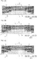
- Fig. 5A illustrates overall thermal image data including data corresponding to a floor A, a wall W1, a wall W2, and a wall W3 of the air-conditioned space (indoor space).
- Fig. 5B is a diagram explaining a reference line L0, a partition line L2, and a partition line L1.
- Fig. 5C is a diagram explaining a boundary line Lm obtained on the basis of temperature variations between the partition lines L2 and L1.
- the floor A is represented by a dashed-lined trapezoidal portion in Fig. 5A .
- the floor A extends in a first direction Dr1 (right-left direction) and a second direction Dr2 (depth direction).
- the floor A, the first direction Dr1, and the second direction Dr2 are concepts in a real space.
- the first direction Dr1 and the second direction Dr2 are parallel to the horizontal direction.
- Fig. 5D illustrates overall thermal image data including data corresponding to a user present in the air-conditioned space (indoor space).
- the floor A represents as a floor area B on overall thermal image data D1.
- the first direction Dr1 in the real space corresponds to the direction of the first coordinate x
- the second direction Dr2 in the real space corresponds to the direction of the second coordinate y.
- the overall thermal image data represents an increase in temperature in a region occupied by the user in the air-conditioned space.
- data corresponding to a certain range of the first coordinate values and a certain range of the second coordinate values represents an increase in temperature.
- the data corresponding to the certain ranges of the first and second coordinate values represents as thermal image data D3.
- the controller Cn can calculate an area corresponding to the floor A using the obtained overall thermal image data D1 (the first function). In other words, the controller Cn can calculate the floor area B on the basis of the overall thermal image data D1.
- a known unit (refer to Japanese Unexamined Patent Application Publication No. 2010-91253 , for example) can be used.
- the controller Cn can perform the first function at predetermined time. Specifically, the controller Cn may perform the first function before the compressor 1 is activated or may perform the first function when the controller Cn receives operation start data from an operation unit (remote control) that transmits operation information.
- an operation unit remote control
- the controller Cn can obtain the floor area B of the air-conditioned space on the basis of temperature variations that is to be generated along a boundary portion between the floor A and the walls of the air-conditioned space.
- the controller Cn has data on the reference line L0 to be used to separate the floor A from the surfaces of the walls W1, W2, and W3.
- the data on the reference line L0 is obtained on the basis of, for example, data on a capacity zone of the air-conditioning apparatus and installation position data about the indoor unit 11 set through, for example, the remote control.
- the reference line L0 does not coincide with the boundary between the floor A and the surfaces of the walls W1, W2, and W3.
- the controller Cn can obtain the partition line L1 and the partition line L2, each of which is a predetermined number of pixels away from the reference line L0.
- the predetermined number of pixels is, for example, two.
- the y coordinate values of the partition line L1, the reference line L0, and the partition line L2 are in descending order. In other words, the reference line L0 is located between the partition line L1 and the partition line L2.
- the controller Cn obtains data on the boundary line Lm that separates the floor A from the surfaces of the walls W1, W2, and W3 on the basis of data that is included in the overall thermal image data D1 and corresponds to a region between the partition lines L1 and L2. In a case where temperature variations in the y direction are large in pixels, the controller Cn calculates the coordinate values of the pixels as the coordinate values of the boundary line Lm. For calculation of temperature variations in the y direction, absolute values in the overall thermal image data D1 may be used or derivatives in the y direction may be used.
- the controller Cn can obtain a region corresponding to the surface of the wall W1 and a region corresponding to the surface of the wall W2 in the same manner.
- the controller Cn can obtain the floor area B corresponding to the floor A on the basis of the data on the boundary line Lm.
- the controller Cn calculates, as the floor area B, a region having y coordinate values greater than those of the boundary line Lm in the overall coordinate range of the overall thermal image data D1.
- a region located below the boundary line Lm in the overall thermal image data D1 corresponds to floor thermal image data D2.
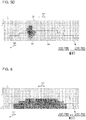
- Fig. 6 illustrates overall thermal image data in the on state of the floor heating device.
- Fig. 6 illustrates an exemplary state of the floor heating device operating in an operation mode for heating the entire floor. The second function will be described below with reference to Fig. 6 .
- the second function is a function of determining, on the basis of floor thermal image data, the presence or absence of a floor heating device in an air-conditioned space.
- the controller Cn determines whether the number of element data items each including a floor temperature within the predetermined temperature range is greater than or equal to the predetermined percentage p1 of the number of element data items corresponding to an intended floor area. When the number of element data items is greater than or equal to the predetermined percentage p1, the controller Cn determines the presence of the floor heating device. For example, the controller Cn sets the intended floor area to the whole of the floor area B. In Fig. 6 , dark portions each represent a floor temperature within the predetermined temperature range. In Fig. 6 , temperatures, specified by temperature data, associated with 70% or more of the element data items corresponding to the floor area B are within the predetermined temperature range. For example, when the percentage p1 is 60%, the controller Cn determines the presence of the floor heating device.
- Fig. 7 illustrates overall thermal image data D1 in the on state of the floor heating device in the operation mode for heating the entire floor A.
- Fig. 8 illustrates overall thermal image data D1 in the on state of the floor heating device under conditions where a piece of furniture is placed on the floor A of the air-conditioned space (indoor space).
- Fig. 7 illustrates a state in which the floor heating device is on and the whole of the floor A (the entire floor area B) is heated.
- thermal image data D4 corresponding to a certain range of the first coordinate values and a certain range of the second coordinate values represents a lower temperature than temperatures represented by data corresponding to regions surrounding the range corresponding to the thermal image data D4.
- the data corresponding to the certain range of the first coordinate values and the certain range of the second coordinate values is illustrated as the thermal image data D4. Consequently, the thermal image data D4 divides thermal image data representing high temperatures.
- the accuracy of determination of the operation state of the floor heating device is reduced by the division of the thermal image data.
- the floor heating device is actually on, a region representing high temperatures is divided into short segments, and thus the floor heating device may be determined to be off.
- the indoor unit 11 according to Embodiment 1 can avoid such an erroneous determination.
- the controller Cn has a function of obtaining overall thermal image data D1 representing a temperature distribution in the infrared detection range of the infrared sensor 9 on the basis of a detection result of the infrared sensor 9. Furthermore, the controller Cn determines, on the basis of floor thermal image data D2 that is included in the overall thermal image data D1 and represents a temperature distribution in the first direction Dr1 of the floor A and the second direction Dr2 intersecting the first direction Dr1, whether the heating device is in the on state.
- the controller Cn determines that the floor heating device is on.
- the determination unit d of the controller Cn uses not a temperature distribution in the first direction Dr1 (direction of the first coordinate x) or the second direction Dr2 (direction of the second coordinate y) but a temperature distribution in both the first direction Dr1 (direction of the first coordinate x) and the second direction Dr2 (direction of the second coordinate y) to determine the operation state of the floor heating device. Consequently, the accuracy of determination of the operation state of the floor heating device can be increased.
- the effect of the increase in determination accuracy is great particularly in a case where a piece of furniture is placed in the air-conditioned space as illustrated in Fig. 8 .
- the controller Cn determines the on state of the floor heating device in the following manner.
- the controller Cn determines that the floor heating device is on.
- the total number of element data items is 270.
- the determination unit d of the controller Cn determines that the floor heating device is on.
- the controller Cn determines the on state of the floor heating device in the following manner.
- the total number of element data items is 270, which is the same as that in Fig. 7 .
- the number of element data items each representing a temperature higher than the first temperature threshold is 163, which is lower than that in Fig. 7 because of the existence of the piece of furniture.
- 163/270 approximately 60.3%, which exceeds the first value.
- Fig. 9 illustrates overall thermal image data D1 in the on state of the floor heating device in an operation mode for heating half of the entire floor A.
- Some floor heating devices have a mode for heating half of the entire floor A and another mode for heating 3/4 of the floor A in addition to the mode for heating the whole of the floor A. In such a mode, the controller Cn can accurately determine whether the floor heating device is on.
- the controller Cn determines that the heating device is on.
- the determination unit d of the indoor unit 11 can determine the on state of the floor heating device even in the mode for heating, for example, half of the entire floor A.
- the first value is equal to a second value.
- the first value may differ from the second value.
- the controller Cn determines the on state of the floor heating device in the following manner.
- the number of element data items belonging to a first range r1 of consecutive first coordinate values x and a second range r2 of consecutive second coordinate values y is 135.
- the first range r1 and the second range r2 are set for the mode for heating half of the floor A.
- the controller Cn has a variety of first ranges r1 and a variety of second ranges r2 for other modes of the floor heating device.
- the controller Cn can determine that the floor heating device is on.
- the controller Cn uses the first temperature threshold. Any other threshold may be used.
- a second temperature threshold e.g., 35 degrees C
- the determination unit d of the controller Cn determines the on state of the heating device in a case where element data items each representing a temperature higher than the first temperature threshold and lower than the second value higher than the first temperature threshold account for the percentage p2 (e.g., 60%) or more of the total number of element data items.
- Floor heating devices achieve temperatures typically ranging from approximately 25 degrees C to approximately 35 degrees C. Setting not only a lower limit (first temperature threshold) but also an upper limit (second temperature threshold) achieves a further increase in accuracy of determination of the operation state of the floor heating device.
- the first and second temperature thresholds may be determined on the basis of a temperature measured by the thermistor 8. Specifically, the controller Cn may set the first temperature threshold to a temperature higher than the temperature measured by the thermistor 8 and set the second temperature threshold to a temperature higher than the first temperature threshold.
- the controller Cn determines the operation state of the floor heating device. Control to be performed in a case where the controller Cn determines the on state of the floor heating device and control to be performed in a case where the controller Cn determines the off state of the floor heating device will be described below.
- the controller Cn determines the off state of the floor heating device
- the controller Cn performs control based on the difference between a set temperature and an indoor temperature (NO in step S1 in Fig. 10 ) or control based on the difference between the indoor temperature and a floor temperature (NO in step S11 in Fig. 12 ). For example, when the floor temperature is significantly lower than the indoor temperature, the controller Cn increases the rotation frequency of the compressor 1. For example, when the floor temperature is significantly lower than a set temperature of the indoor space, the controller Cn increases the rotation frequency of the compressor 1.
- the controller Cn determines that the floor heating device is on, the controller Cn performs control based on a sensible temperature in addition to the difference between the set temperature and the indoor temperature (YES in step S1 in Fig. 10 ) or control based on the difference between the indoor temperature and the floor temperature (YES in step S11 in Fig. 12 ). This operation eliminates or reduces a likelihood that a user may feel a current of cold air.
- Fig. 10 illustrates a control flowchart 1 for the indoor unit 11 according to Embodiment 1.
- the controller Cn determines, during the heating operation, that the floor heating device is on, the controller Cn adjusts the rotation frequency of the compressor 1 on the basis of a set temperature and a sensible temperature obtained by subtracting a temperature correction value (correction value Co1, which will be described later) from a temperature measured by a temperature sensor (thermistor 8). Furthermore, when the difference between the set temperature and the sensible temperature is greater than or equal to a predetermined value, the controller Cn increases the rotation frequency of the compressor 1. Such a configuration will be described below.
- step S0 the floor area B has been obtained, and the presence of a floor heating device has been determined.
- the controller Cn determines whether the floor heating device is on.
- the controller Cn determines whether a value obtained by subtracting the temperature measured by the thermistor 8 from a set temperature of the air-conditioned space set through, for example, the remote control, is greater than or equal to ⁇ 1.
- step S5 When the value is greater than or equal to ⁇ 1, the process proceeds to step S5.
- step S6 When the value is not greater than or equal to ⁇ 1, the process proceeds to step S6.
- the controller Cn increases the rotation frequency of the compressor 1.
- An increase may be a constant or may vary depending on the difference between the set temperature and the indoor temperature. In other words, an increase in rotation frequency of the compressor 1 may be increased as the difference increases.
- the controller Cn makes a determination on the basis of the following expression in step S2.
- the correction value Co1 is a positive value and is not determined on the basis of the floor temperature.
- the sum of the indoor temperature Ta and the correction value Co1 is a value corresponding to the sensible temperature.
- the reason why the correction value Co1 is used is to avoid an erroneous determination that the indoor space is heated in the on state of the floor heating device. Specifically, when the infrared sensor 9 scans the indoor space in the on state of the floor heating device, the floor temperature is high, so that the controller Cn may erroneously determine that the indoor space is heated. In such a case, although the indoor space is not sufficiently heated and the rotation frequency of the compressor 1 should not be reduced, the controller Cn may perform control for reducing the rotation frequency of the compressor 1.
- the controller Cn of the indoor unit 11 uses Expression 1 described above.
- the controller Cn increases the rotation frequency of the compressor 1 (step S3).
- the controller Cn maintains the rotation frequency of the compressor 1 (step S4 in Fig. 10 ).
- An increase in rotation frequency of the compressor 1 may be set greater as the difference between the set temperature and the sensible temperature increases.
- Fig. 11 illustrates a modification of the control flowchart 1 of Fig. 10 .
- a control flowchart 1 according to the modification illustrated in Fig. 11 includes step S4.
- the controller Cn determines whether a predetermined time has elapsed since the increase in the rotation frequency of the compressor 1 in step S3.
- Step S4 is repeated until the predetermined time elapses.
- the process proceeds to step S5, and the control process is terminated.
- the operations in steps S1, S2, S3, and S5 in Fig. 11 are the same as those in steps S1, S2, S3, and S4 in Fig. 10 .
- the controller Cn may reduce the rotation frequency of the compressor 1. For example, when the process proceeds from step S4 to step S5, the controller Cn sets the rotation frequency of the compressor 1 back to the rotation frequency before the rotation frequency is increased in step S3.
- Fig. 12 illustrates a control flowchart 2 for the indoor unit 11 according to Embodiment 1.
- the controller Cn determines, during the heating operation, that the floor heating device is on, the controller Cn maintains or increases the rotation frequency of the compressor 1.
- the controller Cn performs the heating operation.
- step S10 the floor area B has been obtained, and the presence of the floor heating device has been determined.
- the controller Cn determines whether the floor heating device is on.
- the controller Cn determines whether a value (predetermined temperature difference) obtained by subtracting a floor temperature Tfav, obtained from a detection result of the infrared sensor 9, from a temperature measured by the thermistor 8 is greater than or equal to ⁇ 1.
- step S13 When the value is greater than or equal to ⁇ 1, the process proceeds to step S13.
- step S14 When the value is not greater than or equal to ⁇ 1, the process proceeds to step S14.
- the controller Cn increases the rotation frequency of the compressor 1.
- an increase may be a constant or may vary depending on the difference between the temperature measured by the thermistor 8 and the floor temperature Tfav obtained from the detection result of the infrared sensor 9.
- an increase in rotation frequency of the compressor 1 may be increased as the difference increases.
- the value ⁇ 1 is previously set in the controller Cn.
- the value ⁇ 1 may be a variable or a constant.
- Performing the process of the control flowchart 2 of Fig. 12 can obtain substantially the same advantageous effects as those obtained by performing the process of the control flowchart 1 of Fig. 10 .
- step S2 in Fig. 10 the condition that a specified time has not elapsed since activation of the air-conditioning apparatus 10 may be used. Specifically, when the condition in step S2 or the condition that the specified time has not elapsed since the activation of the air-conditioning apparatus 10 is satisfied, the process proceeds to step S3. When neither of the conditions is satisfied, the process proceeds to step S4.
- step S12 in Fig. 12 the condition that the specified time has not elapsed since the activation of the air-conditioning apparatus 10 may also be used. Specifically, when the condition in step S12 or the condition that the specified time has not elapsed since the activation of the air-conditioning apparatus 10 is satisfied, the process proceeds to step S13. When neither of the condition is satisfied, the process proceeds to step S14.
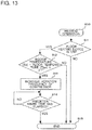
- Fig. 13 illustrates Modification of the control flowchart 2 illustrated in Fig. 12 .
- control flowchart 2 illustrated in Fig. 12 can be modified into a flowchart illustrated in Fig. 13 .
- a long heating operation raises warm air from below in the air-conditioned space, so that the entire air-conditioned space becomes heated. Consequently, the process of the control flowchart 2 illustrated in Fig. 12 is preferable to be performed temporarily.
- the control flowchart 2 according to the modification illustrated in Fig. 13 includes step S14.
- step S14 the controller Cn determines whether a predetermined time has elapsed since the increase in the rotation frequency of the compressor 1 in step S13. Step S14 is repeated until the predetermined time elapses.
- step S15 When the predetermined time has elapsed, the process proceeds to step S15, and the control process is terminated.
- steps S11, S12, S13, and S15 in Fig. 13 are the same as those in steps S11, S12, S13, and S14 in Fig. 12 .
- the controller Cn may reduce the rotation frequency of the compressor 1. For example, when the process proceeds from step S14 to step S15, the controller Cn sets the rotation frequency of the compressor 1 back to the rotation frequency before the rotation frequency is increased in step S13.
- Embodiment 1 whether the floor heating device is on is determined using the infrared sensor 9, and the rotation frequency of the compressor 1 is adjusted, thus achieving comfortable air-conditioning. In other words, in Embodiment 1, comfortable air-conditioning is achieved without communication with the floor heating device.
- the indoor unit 11 of the air-conditioning apparatus 10 converts a detection result of the infrared sensor 9 into overall thermal image data D1 representing a temperature distribution within the infrared detection range of the infrared sensor 9, and determines, on the basis of floor thermal image data D2 that is included in the overall thermal image data D1 and represents a temperature distribution in the first direction Dr1 of the floor and the second direction Dr2 intersecting the first direction Dr1, whether the heating device is on.
- the accuracy of determination of whether the floor heating device is on can be increased.
- the indoor unit 11 of the air-conditioning apparatus 10 according to Embodiment 1 can avoid a reduction in rotation frequency of the compressor 1 in a situation where the rotation frequency of the compressor 1 should not be reduced, even in the on state of the floor heating device. This configuration can reduce or eliminate a reduction in user comfort.
- the indoor unit 11 of the air-conditioning apparatus 10 according to Embodiment 1 can increase the accuracy of detection of the on state of the floor heating device. Consequently, air-conditioning control adjusted for the operation of the floor heating device can be facilitated, thus reducing an increase in power consumption.
- the indoor unit 11 is installed in the same space as the air-conditioned space.
- the indoor unit 11 and the air-conditioned space may be located in another manner.
- the indoor unit 11 of the air-conditioning apparatus 10 may be installed outside the air-conditioned space, and the air outlet of the indoor unit 11 may communicate with the air-conditioned space via a duct.
- the infrared sensor 9 may be separated from the casing 11A of the indoor unit 11, and may be disposed in the air-conditioned space.
- the air-sending fan 5 can be a control target.
- the controller Cn determines, during the heating operation, that the floor heating device is on, the controller Cn adjusts the rotation frequency of the air-sending fan 5 on the basis of a set temperature and a sensible temperature obtained by subtracting a temperature correction value (correction value Co1) from a temperature measured by the temperature sensor (thermistor 8).
- the controller Cn increases the rotation frequency of the air-sending fan 5.
- the controller Cn may reduce the rotation frequency. For example, when a predetermined time has elapsed since the increase in the rotation frequency of the air-sending fan 5, the controller Cn sets the rotation frequency of the air-sending fan 5 back to the rotation frequency before the rotation frequency is increased.
- the controller Cn maintains the rotation frequency of the air-sending fan 5.
- Such a configuration offers advantageous effects similar to those described with reference to Figs. 10 and 11 .
- the air-sending fan 5 can be a control target.
- the controller Cn determines, during the heating operation, that the floor heating device is on, the controller Cn adjusts the rotation frequency of the air-sending fan 5 on the basis of a value (predetermined temperature difference) obtained by subtracting the floor temperature Tfav, obtained from a detection result of the infrared sensor 9, from a temperature measured by the thermistor 8.
- the controller Cn increases the rotation frequency of the air-sending fan 5.
- the controller Cn may reduce the rotation frequency. For example, when a predetermined time has elapsed since the increase in the rotation frequency of the air-sending fan 5, the controller Cn sets the rotation frequency back to the rotation frequency before the rotation frequency is increased.
- the controller Cn maintains the rotation frequency of the air-sending fan 5.
- Such a configuration offers advantageous effects similar to those described with reference to Figs. 12 and 13 .
- the vertical air-directing plate 6 can be a control target. Specifically, when the controller Cn determines that the floor heating device is on, the controller Cn adjusts the angle of the vertical air-directing plate 6 to increase an angle formed by the floor and a virtual plane that is parallel to the vertical air-directing plate 6 and intersects the floor. In other words, the vertical air-directing plate 6 is directed toward the floor. Consequently, the indoor unit 11 increases the amount of air supplied to lower part of the air-conditioned space, compared to that to upper part of the air-conditioned space. Such a configuration prevents the controller Cn from erroneously determining that, due to the floor heated by the floor heating device, the user does not feel cold.
- Embodiment 2 differs from Embodiment 1 in the third function.
- the third function is to determine whether the floor heating device is on.
- the third function is to determine the extent of a heated region of the floor heated by the floor heating device.
- the controller Cn determines whether the area defined by the coordinates of element data items constituting first temperature range element data items is greater than or equal to a predetermined percentage p3 of the floor area B, and determines, on the basis of the determination result, the operation state of the floor heating device.
- the percentage p3 corresponds to a second percentage in the present invention.
- the percentage p1 is 30% and the percentage p2 is 20%.
- Fig. 14 illustrates a control flowchart for an indoor unit 11 according to Embodiment 2.
- the controller Cn performs the heating operation (step S20).
- the controller Cn obtains floor thermal image data D2 on the basis of overall thermal image data D1. In other words, the controller Cn calculates the floor area B of the air-conditioned space.
- the controller Cn determines whether a flag indicating the presence of a floor heating device is set.
- the controller Cn determines whether the area defined by the coordinates of data items included in a predetermined temperature range of the floor thermal image data D2 is greater than or equal to the percentage p1 (e.g., 30%) of the floor area B.
- the data items included in the predetermined temperature range of the floor thermal image data D2 correspond to the first temperature range element data items.
- the predetermined temperature range ranges, for example, from 25 degrees C to 35 degrees C.
- step S24 When the range is greater than or equal to the percentage p1, the process proceeds to step S24.
- the controller Cn sets the flag indicating the presence of the floor heating device.
- the controller Cn determines whether the area defined by the coordinates of data items included in a predetermined temperature range of the floor thermal image data D2 is greater than or equal to the percentage p3 (e.g., 20%) of the floor area B.
- the data items included in the predetermined temperature range of the floor thermal image data D2 correspond to the first temperature range element data items.
- the predetermined temperature range ranges, for example, from 25 degrees C to 35 degrees C.
- step S27 When the range is greater than or equal to the percentage p3, the process proceeds to step S27.
- step S26 When the range is not greater than or equal to the percentage p3, the process proceeds to step S26.
- step S26 the area defined by the coordinates of the element data items constituting the first temperature range element data items is less than the percentage p3 of the floor area B.
- the controller Cn maintains the rotation frequency of the compressor 1.
- step S27 the area defined by the coordinates of the element data items constituting the first temperature range element data items is greater than or equal to the percentage p3 of the floor area B.
- the controller Cn reduces the rotation frequency of the compressor 1. A reduction can be set depending on the extent of the area defined by the coordinates of the element data items constituting the first temperature range element data items.
- the reduction is set to x1 when the area defined by the coordinates of the element data items constituting the first temperature range element data items is greater than or equal to 20% and less than 50% of the floor area B, the reduction is set to x2 when the range is greater than or equal to 50% and less than 80% of the floor area B, and the reduction is set to x3 when the range is greater than or equal to 80%.
- an inequation is satisfied that x3 > x2 > x1.
- a reduction in rotation frequency of the compressor 1 is increased as the area defined by the coordinates of the element data items constituting the first temperature range element data items increases.
- the controller Cn determines whether a value (predetermined temperature difference) obtained by subtracting the floor temperature Tfav, obtained from a detection result of the infrared sensor 9, from a temperature (indoor temperature Ta) measured by the thermistor 8 is less than or equal to V.
- the floor temperature Tfav can be obtained by, for example, averaging temperatures represented by temperature data items included in element data items in a certain range.
- the controller Cn terminates the control process illustrated in Fig. 14 .
- the infrared sensor 9 is used to obtain data on the extent of a heated region of the floor heated by the floor heating device, and the rotation frequency of the compressor 1 is adjusted on the basis of the obtained data, thus achieving comfortable air-conditioning.
- comfortable air-conditioning can be achieved without communication with the floor heating device.
- Embodiment 2 as the heated region of the floor heated by the floor heating device increases, a reduction in rotation frequency of the compressor 1 is increased. This setting can reduce power consumption and increase the user comfort.
- the percentage p3 is less than the percentage p1.
- the percentage p1 which is greater than the percentage p3, tightens a criterion for determining the presence or absence of a floor heating device. This setting can avoid an erroneous determination of the presence or absence of a floor heating device.
- the rotation frequency of the compressor 1 can be appropriately adjusted in Embodiment 2 even when the heated region of the floor heated by the floor heating device decreases. Consequently, more finely adjusted air-conditioning can be achieved.
- the rotation frequency of the compressor 1 is adjusted on the basis of the indoor temperature Ta and the floor temperature Tfav. Specifically, the controller Cn reduces the rotation frequency of the compressor 1 when the floor temperature Tfav approaches the indoor temperature Ta. This operation can reduce the power consumption and increase the user comfort.
Landscapes
- Engineering & Computer Science (AREA)
- Chemical & Material Sciences (AREA)
- Combustion & Propulsion (AREA)
- Mechanical Engineering (AREA)
- General Engineering & Computer Science (AREA)
- Physics & Mathematics (AREA)
- Thermal Sciences (AREA)
- Fluid Mechanics (AREA)
- General Physics & Mathematics (AREA)
- Spectroscopy & Molecular Physics (AREA)
- Air Conditioning Control Device (AREA)
Abstract
Description
- The present invention relates to indoor units of air-conditioning apparatuses, and in particular, relates to an air-conditioning-apparatus indoor unit capable of determining an operation state of a floor heating device.
- A recently developed system includes an air-conditioning apparatus and a floor heating device that operate in collaboration with each other (refer to, for example, Patent Literature 1). In the related-art system described in
Patent Literature 1, both the floor heating device and an indoor unit of the air-conditioning apparatus are controlled on the basis of detection data from an infrared sensor. - Patent Literature 1: Japanese Unexamined Patent Application Publication No.
11-153328 - In the above-described related-art system, a controller obtains not only data on the air-conditioning apparatus but also data on the floor heating device to control various devices. In other words, the related-art system needs to be configured to communicate with the floor heating device, and its versatility decreases, accordingly.
- The present invention has been made to overcome the above-described disadvantages, and aims to provide an air-conditioning-apparatus indoor unit capable of achieving comfortable air-conditioning without communicating with a floor heating device.
- An air-conditioning-apparatus indoor unit according to an embodiment of the present invention includes a casing, an infrared sensor disposed on the casing and configured to detect infrared radiation emitted to an air-conditioned space, and a controller to which the infrared sensor outputs a detection result. The controller is configured to convert the detection result of the infrared sensor into overall thermal image data representing a temperature distribution within an infrared detection range of the infrared sensor, calculate, on the basis of the overall thermal image data, a floor area of the air-conditioned space, and obtain, on the basis of the overall thermal image data, floor thermal image data including a plurality of element data items each including coordinates within the floor area and a floor temperature within the floor area associated with the coordinates. The controller is configured to determine, on the basis of the floor thermal image data, presence or absence of a floor heating device in the air-conditioned space. When the controller determines the presence of the floor heating device, the controller is configured to determine, on the basis of data that is included in the floor thermal image data and corresponds to an installation region of the floor heating device, an operation state of the floor heating device.
- With the above-described configuration, the air-conditioning-apparatus indoor unit according to an embodiment of the present invention can achieve comfortable air-conditioning without communicating with the floor heating device.
-
-
Fig. 1 is a schematic diagram illustrating an exemplary configuration of an air-conditioning apparatus including an indoor unit according toEmbodiment 1 of the present invention. -
Fig. 2 is a perspective view of the indoor unit according toEmbodiment 1 of the present invention. -
Fig. 3 is a diagram explaining an infrared sensor of the indoor unit according toEmbodiment 1 of the present invention. -
Fig. 4 is a diagram illustrating vertical light-distribution view angles of the infrared sensor of the indoor unit according toEmbodiment 1 of the present invention. -
Fig. 5A illustrates overall thermal image data including data corresponding to a floor and walls of an air-conditioned space (indoor space). -
Fig. 5B is a diagram explaining a reference line, a partition line, and another partition line. -
Fig. 5C is a diagram explaining a boundary line obtained on the basis of temperature variations between the partition lines. -
Fig. 5D illustrates overall thermal image data including data corresponding to a user present in the air-conditioned space (indoor space). -
Fig. 6 illustrates overall thermal image data in an on state of a floor heating device. -
Fig. 7 illustrates overall thermal image data in the on state of the floor heating device in an operation mode for heating the entire floor. -
Fig. 8 illustrates overall thermal image data in the on state of the floor heating device under conditions where a piece of furniture is placed on the floor of the air-conditioned space (indoor space). -
Fig. 9 illustrates overall thermal image data in the on state of the floor heating device in an operation mode for heating half of the floor. -
Fig. 10 illustrates acontrol flowchart 1 for the indoor unit according toEmbodiment 1 of the present invention. -
Fig. 11 illustrates a modification of thecontrol flowchart 1 illustrated inFig. 10 . -
Fig. 12 illustrates acontrol flowchart 2 for the indoor unit according toEmbodiment 1 of the present invention. -
Fig. 13 illustrates a modification of thecontrol flowchart 1 illustrated inFig. 12 . -
Fig. 14 illustrates a control flowchart for an indoor unit according toEmbodiment 2 of the present invention. - Embodiments of an air-conditioning-apparatus indoor unit according to the present invention will be described below with reference to the drawings. The present invention is not limited to the following embodiments. Note that the relative sizes of components illustrated in the following figures including
Fig. 1 may differ from actual relative sizes. -
Fig. 1 is a schematic diagram illustrating an exemplary configuration of an air-conditioning apparatus 10 including anindoor unit 11 according toEmbodiment 1.Fig. 2 is a perspective view of theindoor unit 11 according to Embodiment 1. The configuration of the air-conditioning apparatus 10 will be described below with reference toFigs. 1 and 2 . The term "air-conditioned space" inEmbodiment 1 refers to, for example, an indoor space in which theindoor unit 11 is installed. - The air-
conditioning apparatus 10 includes theindoor unit 11 and anoutdoor unit 12. Theindoor unit 11 and theoutdoor unit 12 are connected by refrigerant pipes P. - The air-
conditioning apparatus 10 includes acompressor 1, a four-way valve 1B, anoutdoor heat exchanger 2, anexpansion device 3, and anindoor heat exchanger 4. Thecompressor 1, the four-way valve 1B, theoutdoor heat exchanger 2, theexpansion device 3, and theindoor heat exchanger 4 are connected by the refrigerant pipes P. - The
indoor unit 11 houses theindoor heat exchanger 4 and an air-sendingfan 5. Theoutdoor unit 12 houses thecompressor 1, the four-way valve 1B, theoutdoor heat exchanger 2, and theexpansion device 3. Theexpansion device 3 may be disposed outside theoutdoor unit 12 and theindoor unit 11 or may be disposed in theindoor unit 11. - The air-
conditioning apparatus 10 further includes the air-sendingfan 5 provided to theindoor heat exchanger 4. - In addition, the air-
conditioning apparatus 10 includes aninfrared sensor 9 disposed on theindoor unit 11, athermistor 8 disposed on theindoor unit 11, a horizontal air-directingplate 7 for adjusting the direction of air supplied from theindoor unit 11 to the air-conditioned space horizontally or in a right-left direction, and a vertical air-directingplate 6 for adjusting the direction of air supplied from theindoor unit 11 to the air-conditioned space vertically or in an up-down direction. - The air-
conditioning apparatus 10 further includes a controller Cn. The controller Cn includes a controller Cn1 disposed in theindoor unit 11 and a controller Cn2 disposed in theoutdoor unit 12. - The
compressor 1 compresses and discharges refrigerant. Thecompressor 1 is connected at its discharge portion and its suction portion to the four-way valve 1B. - The four-
way valve 1B is a refrigerant flow switching device. The four-way valve 1B is capable of switching between a first position to connect the discharge portion of thecompressor 1 to theoutdoor heat exchanger 2 and connect the suction portion of thecompressor 1 to theindoor heat exchanger 4 and a second position to connect the discharge portion of thecompressor 1 to theindoor heat exchanger 4 and connect the suction portion of thecompressor 1 to theoutdoor heat exchanger 2. - The
outdoor heat exchanger 2 is connected at one end to the four-way valve 1B, and is connected at the other end to theexpansion device 3. Theoutdoor heat exchanger 2 may be, for example, a finned-tube heat exchanger. Theoutdoor heat exchanger 2 acts as an evaporator when the air-conditioning apparatus 10 performs a heating operation, and acts as a condenser (radiator) when the air-conditioning apparatus 10 performs a cooling operation. - The
expansion device 3 is connected at one end to theoutdoor heat exchanger 2, and is connected at the other end to theindoor heat exchanger 4. Theexpansion device 3 may include a pressure reducing valve capable of adjusting the amount of expansion or may include a capillary tube. - The
indoor heat exchanger 4 is connected at one end to theexpansion device 3, and is connected at the other end to the four-way valve 1B. Theindoor heat exchanger 4 may be, for example, a finned-tube heat exchanger. Theindoor heat exchanger 4 acts as a condenser when the air-conditioning apparatus 10 performs the heating operation, and acts as an evaporator when the air-conditioning apparatus 10 performs the cooling operation. - The air-sending
fan 5 is disposed in theindoor unit 11. Specifically, theindoor unit 11 includes acasing 11A, serving as a shell, and the air-sendingfan 5 is disposed in thecasing 11A. Thecasing 11A has an air inlet and an air outlet. The operation of the air-sendingfan 5 causes air to be sucked into thecasing 11A through the air inlet and causes air in thecasing 11A to flow out of thecasing 11A through the air outlet. Although not illustrated, an air-sending fan may be provided to theoutdoor heat exchanger 2. - The
infrared sensor 9, which is disposed on thecasing 11A, detects infrared radiation emitted to the air-conditioned space. Theinfrared sensor 9 is disposed on lower part of thecasing 11A. Specifically, theinfrared sensor 9 protrudes from a lower surface of thecasing 11A, and is located at a position close to one end of thecasing 11A in the longitudinal direction of thecasing 11A. Theinfrared sensor 9 is rotated by a stepping motor (not illustrated), and is capable of scanning infrared radiation in the air-conditioned space. Theinfrared sensor 9 outputs a detection result (infrared radiation temperature data) to the controller Cn. - The
thermistor 8, which is disposed on thecasing 11A, measures the temperature of the air-conditioned space. Thethermistor 8 outputs a measurement result (indoor temperature data) to the controller Cn. - The horizontal air-directing
plate 7 is disposed in the air outlet of thecasing 11A. The horizontal air-directingplate 7 is, for example, a plate-shaped part. The horizontal air-directingplate 7 is fixed to a shaft (not illustrated). The movement of the shaft causes the horizontal air-directingplate 7 to rotate from side to side, or horizontally. Thus, the air-conditioning apparatus 10 can adjust the direction of air blown from the air outlet of thecasing 11A horizontally. - The vertical air-directing
plate 6 is disposed in the air outlet of thecasing 11A, and is located adjacent to the horizontal air-directingplate 7. The vertical air-directingplate 6, the horizontal air-directingplate 7, is, for example, a plate-shaped part. The horizontal air-directingplate 7 is fixed to a shaft (not illustrated). The movement of the shaft causes the horizontal air-directingplate 7 to rotate from side to side, or horizontally. Thus, the air-conditioning apparatus 10 can adjust the direction of air blown from the air outlet of thecasing 11A horizontally. - The controller Cn has at least three functions: a first function of calculating a floor area of the air-conditioned space; a second function of determining the presence or absence of a floor heating device installed in the air-conditioned space; and a third function of determining an operation state of the floor heating device. In
Embodiment 1, the third function corresponds to a function of determining, on the basis of a detection result of theinfrared sensor 9, whether the floor heating device installed under the floor of the air-conditioned space is in an on state. In other words, the operation state inEmbodiment 1 corresponds to the on state or an off state of the floor heating device. - The first function of the controller Cn is achieved as follows, for example. The controller Cn converts a detection result of the
infrared sensor 9 into overall thermal image data representing a temperature distribution within an infrared detection range of theinfrared sensor 9, and calculates the floor area of the air-conditioned space on the basis of the overall thermal image data obtained by the conversion. The controller Cn obtains, on the basis of the overall thermal image data, floor thermal image data including a plurality of element data items each including coordinates within the floor area and a floor temperature within the floor area associated with the coordinates. - The second function of the controller Cn is achieved as follows, for example. The controller Cn determines, on the basis of the floor thermal image data, the presence or absence of a floor heating device in the air-conditioned space. Specifically, the floor thermal image data is composed of first temperature range element data items composed of the element data items each including floor temperature within a predetermined temperature range and second temperature range element data items composed of the element data items each including floor temperature outside the predetermined temperature range. When the presence of the floor heating device is determined (the second function), the area defined by the coordinates of the element data items constituting the first temperature range element data items is greater than or equal to a predetermined percentage p1 of an intended floor area. The percentage p1 corresponds to a first percentage in the present invention. For the intended floor area, for example, the whole of the floor area can be used. When the controller Cn determines the presence of the floor heating device, the controller Cn sets a flag indicating the presence of the floor heating device. In this case, the controller Cn has determined the presence of the floor heating device in the area defined by the coordinates of the element data items constituting the first temperature range element data items.
- The third function of the controller Cn is achieved as follows, for example. When the controller Cn determines the presence of the floor heating device, the controller Cn determines, on the basis of data that is included in the floor thermal image data and corresponds to an installation region of the floor heating device, the operation state of the floor heating device. In
Embodiment 1, the third function is achieved, for example, in a manner similar to the second function. Specifically, when the on state of the floor heating device is determined (the third function), the area defined by the coordinates of the element data items constituting the first temperature range element data items is greater than or equal to a predetermined percentage p2 of the intended floor area. The percentage p1 and the percentage p2 may be the same or different from each other. - The controller Cn includes the controller Cn1 disposed in the
indoor unit 11 and the controller Cn2 disposed in theoutdoor unit 12. The controller Cn1 and the controller Cn2 communicate with each other, and control various actuators for thecompressor 1 and other devices in collaboration with each other. - The controller Cn1 includes an
actuator control unit 15, amemory 18, anarithmetic unit 20, and atime measuring unit 21. The controller Cn2 includes a compressor rotation-frequency control unit 32 and an indoor-temperature adjusting unit 31. In the following description, thearithmetic unit 20 and the indoor-temperature adjusting unit 31 may also be collectively referred to as a determination unit d. - The
actuator control unit 15 controls, for example, motors for the vertical air-directingplate 6, the horizontal air-directingplate 7, and the air-sendingfan 5, on the basis of a determination result of the determination unit d, for example. - The
memory 18 stores data including temperature data that is a measurement result of thethermistor 8, and the overall thermal image data based on a detection result of theinfrared sensor 9. The overall thermal image data will be described below. - The overall thermal image data is obtained by scanning the air-conditioned space through the
infrared sensor 9. - The overall thermal image data includes floor thermal image data and wall image data. When the scan range of the
infrared sensor 9 includes no walls and only the floor is a target located within the scan range, the overall thermal image data will not include wall image data. - The overall thermal image data is composed of a plurality of element data items. The floor thermal image data is composed of a plurality of element data items, and the wall image data is also composed of a plurality of element data items.
- Each element data item, or element data, is data corresponding to the least significant bit (LSB), which is a minimum unit of thermal data obtained by the
infrared sensor 9. The element data includes coordinate data (x, y) and temperature data (T) associated with the coordinate data. The element data is associated with the coordinate data representing a first coordinate x in a first direction and a second coordinate y in a second direction and the temperature data T representing a floor temperature at a position defined by the first coordinate x and the second coordinate y. In other words, the element data can be expressed as (x, y, T). - The
arithmetic unit 20 has the above-described first, second, and third functions. - The
time measuring unit 21 has a function of measuring various time lengths. For example, thetime measuring unit 21 measures time that has elapsed since activation of the air-conditioning apparatus 10. - The indoor-
temperature adjusting unit 31 gives an instruction to the compressor rotation-frequency control unit 32 to control thecompressor 1 on the basis of a determination result of thearithmetic unit 20 and a detection result of theinfrared sensor 9. For example, when thearithmetic unit 20 determines that the floor heating device is on, the indoor-temperature adjusting unit 31 gives an instruction to the compressor rotation-frequency control unit 32 to increase, reduce, or maintain the rotation frequency of thecompressor 1. - In the heating operation, the refrigerant discharged from the
compressor 1 is supplied to theindoor heat exchanger 4 through the four-way valve 1B. In other words, theindoor heat exchanger 4 acts as a condenser. The refrigerant supplied to theindoor heat exchanger 4 exchanges heat with air supplied by the air-sendingfan 5, and thus condenses and liquifies. The refrigerant leaving theindoor heat exchanger 4 is reduced in pressure by theexpansion device 3, so that the refrigerant turns into low-temperature, low-pressure, two-phase gas-liquid refrigerant. The refrigerant leaving theexpansion device 3 is supplied to theoutdoor heat exchanger 2. In other words, theoutdoor heat exchanger 2 acts as an evaporator. The refrigerant supplied to theoutdoor heat exchanger 2 evaporates and gasifies. The refrigerant leaving theoutdoor heat exchanger 2 passes through the four-way valve 1B, and is returned to the discharge portion of thecompressor 1. - In the cooling operation, the refrigerant flows in a direction opposite to that in the heating operation.
-
Fig. 3 is a diagram explaining theinfrared sensor 9 of theindoor unit 11 according toEmbodiment 1. - The
infrared sensor 9 is mounted on thecasing 11A such that theinfrared sensor 9 faces downward (for example, at a depression angle of approximately 24.5 degrees) to the floor. - As illustrated in
Fig. 3 , theinfrared sensor 9 includes acylindrical part 9A made of metal and eight light-receiving elements (not illustrated) arranged in the cylindrical part. The eight light-receiving elements are vertically arranged in a straight line. Thecylindrical part 9A has an end with a lens window (not illustrated) through which infrared radiation can enter and reach the light-receiving elements. A light-distribution view angle 9B of each light-receiving element is defined by a vertical light-distribution view angle 9B1 of 7 degrees and a horizontal light-distribution view angle 9B2 of 8 degrees. - Although the above-described light-
distribution view angle 9B of each light-receiving element extends 7 degrees vertically and 8 degrees horizontally, the view angles are not limited to 7 degrees in the vertical direction and 8 degrees in the horizontal direction. The number of light-receiving elements varies depending on the light-distribution view angle 9B of each light-receiving element. For example, it is only required that the product of the vertical light-distribution view angle 9B1 of each light-receiving element and the number of light-receiving elements is constant. - The
infrared sensor 9 can be rotated from side to side within a predetermined angle range by the action of, for example, the stepping motor (not illustrated). Specifically, theinfrared sensor 9 can scan, for example, the floor and the walls within a predetermined range. In this case, each time the stepping motor rotates by 1.6 degrees, the stepping motor stops rotating for a predetermined time (0.1 to 0.2 seconds), and data for thermal image data on the floor and the walls is obtained from the light-receiving elements of theinfrared sensor 9. - The operation of rotating the stepping motor by 1.6 degrees and the operation of obtaining thermal image data from the light-receiving elements are repeated, so that the
infrared sensor 9 can obtain data for overall thermal image data. When an upper limit and a lower limit of the rotation angle of the stepping motor are set, the stepping motor operates as follows. For example, the stepping motor (infrared sensor 9) starts to rotate from the lower limit of the rotation angle. The rotation angle of the stepping motor (infrared sensor 9) increases to reach the upper limit, and then decreases from the upper limit to the lower limit. - The
infrared sensor 9 combines data for thermal image data items obtained for respective rotation angle ranges of the stepping motor into data for overall thermal image data. InEmbodiment 1, the stepping motor has 94 rotation angle ranges. In other words, the angle of rotation of theinfrared sensor 9 is approximately 150.4 degrees. Theinfrared sensor 9 obtains 94 thermal image data items by scanning an area corresponding to the range from the lower limit to the upper limit of the rotation angle of the stepping motor. The controller Cn generates overall thermal image data on the basis of the 94 thermal image data items. -
Fig. 4 is a diagram illustrating vertical light-distribution view angles of theinfrared sensor 9 of theindoor unit 11 according toEmbodiment 1.Fig. 4 illustrates the vertical light-distribution view angles under conditions where theindoor unit 11 is installed at a level of 1,800 mm from the floor of the indoor space. The vertical light-distribution view angle 9B1 of one light-receiving element is 7 degrees.Fig. 4 further illustrates an overall light-distribution view angle 9B3 corresponding to the vertical light-distribution view angles of all of the light-receiving elements. An angle range 9B4 is outside the overall light-distribution view angle 9B3 of theinfrared sensor 9. The angle range 9B4 is an angle formed by a reference wall, on which theindoor unit 11 is mounted, and a lower limit of the overall light-distribution view angle 9B3. - When the depression angle of the
infrared sensor 9 is 0 degrees, an equation is satisfied that the angle range 9B4 = 90 degrees - 4 (the number of light-receiving elements whose vertical light-distribution view angle 9B1 is less than 0 degrees when the horizontal direction is 0 degrees) × 7 degrees (vertical light-distribution view angle of one light-receiving element) = 62 degrees. As theinfrared sensor 9 inEmbodiment 1 is at a depression angle of 24.5 degrees, an equation is satisfied that the angle range 9B4 = 62 degrees - 24.5 degrees = 37.5 degrees. -
Fig. 5A illustrates overall thermal image data including data corresponding to a floor A, a wall W1, a wall W2, and a wall W3 of the air-conditioned space (indoor space).Fig. 5B is a diagram explaining a reference line L0, a partition line L2, and a partition line L1.Fig. 5C is a diagram explaining a boundary line Lm obtained on the basis of temperature variations between the partition lines L2 and L1. The floor A is represented by a dashed-lined trapezoidal portion inFig. 5A . The floor A extends in a first direction Dr1 (right-left direction) and a second direction Dr2 (depth direction). The floor A, the first direction Dr1, and the second direction Dr2 are concepts in a real space. The first direction Dr1 and the second direction Dr2 are parallel to the horizontal direction. -
Fig. 5D illustrates overall thermal image data including data corresponding to a user present in the air-conditioned space (indoor space). As illustrated inFig. 5D , the floor A represents as a floor area B on overall thermal image data D1. On the overall thermal image data, the first direction Dr1 in the real space corresponds to the direction of the first coordinate x, and the second direction Dr2 in the real space corresponds to the direction of the second coordinate y. - As illustrated in
Fig. 5D , the overall thermal image data represents an increase in temperature in a region occupied by the user in the air-conditioned space. InFig. 5D , data corresponding to a certain range of the first coordinate values and a certain range of the second coordinate values represents an increase in temperature. InFig. 5D , the data corresponding to the certain ranges of the first and second coordinate values represents as thermal image data D3. - The controller Cn can calculate an area corresponding to the floor A using the obtained overall thermal image data D1 (the first function). In other words, the controller Cn can calculate the floor area B on the basis of the overall thermal image data D1. For such a calculation unit, a known unit (refer to Japanese Unexamined Patent Application Publication No.
2010-91253 - The controller Cn can perform the first function at predetermined time. Specifically, the controller Cn may perform the first function before the
compressor 1 is activated or may perform the first function when the controller Cn receives operation start data from an operation unit (remote control) that transmits operation information. - For example, the controller Cn can obtain the floor area B of the air-conditioned space on the basis of temperature variations that is to be generated along a boundary portion between the floor A and the walls of the air-conditioned space.
- As illustrated in
Fig. 5B , the controller Cn has data on the reference line L0 to be used to separate the floor A from the surfaces of the walls W1, W2, and W3. The data on the reference line L0 is obtained on the basis of, for example, data on a capacity zone of the air-conditioning apparatus and installation position data about theindoor unit 11 set through, for example, the remote control. As illustrated inFig. 5B , the reference line L0 does not coincide with the boundary between the floor A and the surfaces of the walls W1, W2, and W3. - The controller Cn can obtain the partition line L1 and the partition line L2, each of which is a predetermined number of pixels away from the reference line L0. In this case, the predetermined number of pixels is, for example, two. The y coordinate values of the partition line L1, the reference line L0, and the partition line L2 are in descending order. In other words, the reference line L0 is located between the partition line L1 and the partition line L2.
- The controller Cn obtains data on the boundary line Lm that separates the floor A from the surfaces of the walls W1, W2, and W3 on the basis of data that is included in the overall thermal image data D1 and corresponds to a region between the partition lines L1 and L2. In a case where temperature variations in the y direction are large in pixels, the controller Cn calculates the coordinate values of the pixels as the coordinate values of the boundary line Lm. For calculation of temperature variations in the y direction, absolute values in the overall thermal image data D1 may be used or derivatives in the y direction may be used.
- How to separate the floor A from the surfaces of the walls W1, W2, and W3 has been described above. The controller Cn can obtain a region corresponding to the surface of the wall W1 and a region corresponding to the surface of the wall W2 in the same manner.
- The controller Cn can obtain the floor area B corresponding to the floor A on the basis of the data on the boundary line Lm. The controller Cn calculates, as the floor area B, a region having y coordinate values greater than those of the boundary line Lm in the overall coordinate range of the overall thermal image data D1. In other words, in
Fig. 5C , a region located below the boundary line Lm in the overall thermal image data D1 corresponds to floor thermal image data D2. -
Fig. 6 illustrates overall thermal image data in the on state of the floor heating device.Fig. 6 illustrates an exemplary state of the floor heating device operating in an operation mode for heating the entire floor. The second function will be described below with reference toFig. 6 . - The second function is a function of determining, on the basis of floor thermal image data, the presence or absence of a floor heating device in an air-conditioned space. The controller Cn determines whether the number of element data items each including a floor temperature within the predetermined temperature range is greater than or equal to the predetermined percentage p1 of the number of element data items corresponding to an intended floor area. When the number of element data items is greater than or equal to the predetermined percentage p1, the controller Cn determines the presence of the floor heating device. For example, the controller Cn sets the intended floor area to the whole of the floor area B. In
Fig. 6 , dark portions each represent a floor temperature within the predetermined temperature range. InFig. 6 , temperatures, specified by temperature data, associated with 70% or more of the element data items corresponding to the floor area B are within the predetermined temperature range. For example, when the percentage p1 is 60%, the controller Cn determines the presence of the floor heating device. -
Fig. 7 illustrates overall thermal image data D1 in the on state of the floor heating device in the operation mode for heating the entire floor A. -
Fig. 8 illustrates overall thermal image data D1 in the on state of the floor heating device under conditions where a piece of furniture is placed on the floor A of the air-conditioned space (indoor space). -
Fig. 7 illustrates a state in which the floor heating device is on and the whole of the floor A (the entire floor area B) is heated. - However, even when the whole of the floor A is heated, a piece of furniture, such as a sofa and a table, in the air-conditioned space will block part of infrared radiation emitted from the floor A. Consequently, thermal image data D4 corresponding to a certain range of the first coordinate values and a certain range of the second coordinate values represents a lower temperature than temperatures represented by data corresponding to regions surrounding the range corresponding to the thermal image data D4. In
Fig. 8 , the data corresponding to the certain range of the first coordinate values and the certain range of the second coordinate values is illustrated as the thermal image data D4. Consequently, the thermal image data D4 divides thermal image data representing high temperatures. For example, when the operation state of the floor heating device is determined only on the basis of a temperature distribution in the first direction (direction of the first coordinate x) or a temperature distribution in the second direction (direction of the second coordinate y), the accuracy of determination of the operation state of the floor heating device is reduced by the division of the thermal image data. In other words, although the floor heating device is actually on, a region representing high temperatures is divided into short segments, and thus the floor heating device may be determined to be off. Theindoor unit 11 according toEmbodiment 1 can avoid such an erroneous determination. - The controller Cn has a function of obtaining overall thermal image data D1 representing a temperature distribution in the infrared detection range of the
infrared sensor 9 on the basis of a detection result of theinfrared sensor 9. Furthermore, the controller Cn determines, on the basis of floor thermal image data D2 that is included in the overall thermal image data D1 and represents a temperature distribution in the first direction Dr1 of the floor A and the second direction Dr2 intersecting the first direction Dr1, whether the heating device is in the on state. - Specifically, when element data items each representing a temperature higher than a first temperature threshold account for a predetermined percentage p2 or more of a predetermined number of element data items, the controller Cn determines that the floor heating device is on. As described above, the determination unit d of the controller Cn uses not a temperature distribution in the first direction Dr1 (direction of the first coordinate x) or the second direction Dr2 (direction of the second coordinate y) but a temperature distribution in both the first direction Dr1 (direction of the first coordinate x) and the second direction Dr2 (direction of the second coordinate y) to determine the operation state of the floor heating device. Consequently, the accuracy of determination of the operation state of the floor heating device can be increased. The effect of the increase in determination accuracy is great particularly in a case where a piece of furniture is placed in the air-conditioned space as illustrated in
Fig. 8 . - In the case illustrated in
Fig. 7 , the controller Cn determines the on state of the floor heating device in the following manner. - In the case where element data items each representing a temperature higher than the first temperature threshold (e.g., 25 degrees C) account for the percentage p2 (e.g., 60%) or more of the total number of element data items, the controller Cn determines that the floor heating device is on.
- In
Fig. 7 , the total number of element data items is 270. The number of element data items each representing a temperature higher than the first temperature threshold is 193. Consequently, an equation is satisfied that 193/270 = approximately 71%, which exceeds a first value. Thus, the determination unit d of the controller Cn determines that the floor heating device is on. - In the case illustrated in
Fig. 8 , the controller Cn determines the on state of the floor heating device in the following manner. - In
Fig. 8 , the total number of element data items is 270, which is the same as that inFig. 7 . In this case, the number of element data items each representing a temperature higher than the first temperature threshold is 163, which is lower than that inFig. 7 because of the existence of the piece of furniture. However, an equation is satisfied that 163/270 = approximately 60.3%, which exceeds the first value. Thus, the determination unit d of the controller Cn can determine that the floor heating device is on. In other words, even when the thermal image data D4 divides the thermal image data representing high temperatures, the controller Cn can determine that the floor heating device is on. -
Fig. 9 illustrates overall thermal image data D1 in the on state of the floor heating device in an operation mode for heating half of the entire floor A. - Some floor heating devices have a mode for heating half of the entire floor A and another mode for
heating 3/4 of the floor A in addition to the mode for heating the whole of the floor A. In such a mode, the controller Cn can accurately determine whether the floor heating device is on. - In a case where element data items each representing a temperature higher than the first temperature threshold (e.g., 25 degrees C) account for the percentage p2 (e.g., 60%) or more of element data items belonging to a first range of consecutive first coordinate values x and a second range of consecutive second coordinate values y, the controller Cn determines that the heating device is on.
- With such a configuration, the determination unit d of the
indoor unit 11 can determine the on state of the floor heating device even in the mode for heating, for example, half of the entire floor A. In the above description, the first value is equal to a second value. The first value may differ from the second value. - In the case illustrated in
Fig. 9 , the controller Cn determines the on state of the floor heating device in the following manner. - In
Fig. 9 , the number of element data items belonging to a first range r1 of consecutive first coordinate values x and a second range r2 of consecutive second coordinate values y is 135. In the controller Cn, the first range r1 and the second range r2 are set for the mode for heating half of the floor A. The controller Cn has a variety of first ranges r1 and a variety of second ranges r2 for other modes of the floor heating device. - In this case, the number of element data items each representing a temperature higher than the first temperature threshold is 90, and an equation is satisfied that 90/135 = approximately 66.6%, which exceeds the second value. Thus, the controller Cn can determine that the floor heating device is on.
- In the above description with reference to
Figs. 7 to 9 , the controller Cn uses the first temperature threshold. Any other threshold may be used. For example, a second temperature threshold (e.g., 35 degrees C) greater than the first temperature threshold may be set in addition to the first temperature threshold in the controller Cn. Specifically, the determination unit d of the controller Cn determines the on state of the heating device in a case where element data items each representing a temperature higher than the first temperature threshold and lower than the second value higher than the first temperature threshold account for the percentage p2 (e.g., 60%) or more of the total number of element data items. Floor heating devices achieve temperatures typically ranging from approximately 25 degrees C to approximately 35 degrees C. Setting not only a lower limit (first temperature threshold) but also an upper limit (second temperature threshold) achieves a further increase in accuracy of determination of the operation state of the floor heating device. - As regards how to determine the first and second temperature thresholds, although 25 degrees C and 35 degrees C are used as examples in the above description, any other values may be used. The first and second temperature thresholds may be determined on the basis of a temperature measured by the
thermistor 8. Specifically, the controller Cn may set the first temperature threshold to a temperature higher than the temperature measured by thethermistor 8 and set the second temperature threshold to a temperature higher than the first temperature threshold. - For the third function, the controller Cn determines the operation state of the floor heating device. Control to be performed in a case where the controller Cn determines the on state of the floor heating device and control to be performed in a case where the controller Cn determines the off state of the floor heating device will be described below. In the case where the controller Cn determines the off state of the floor heating device, the controller Cn performs control based on the difference between a set temperature and an indoor temperature (NO in step S1 in
Fig. 10 ) or control based on the difference between the indoor temperature and a floor temperature (NO in step S11 inFig. 12 ). For example, when the floor temperature is significantly lower than the indoor temperature, the controller Cn increases the rotation frequency of thecompressor 1. For example, when the floor temperature is significantly lower than a set temperature of the indoor space, the controller Cn increases the rotation frequency of thecompressor 1. - When the controller Cn determines that the floor heating device is on, the controller Cn performs control based on a sensible temperature in addition to the difference between the set temperature and the indoor temperature (YES in step S1 in
Fig. 10 ) or control based on the difference between the indoor temperature and the floor temperature (YES in step S11 inFig. 12 ). This operation eliminates or reduces a likelihood that a user may feel a current of cold air. -
Fig. 10 illustrates acontrol flowchart 1 for theindoor unit 11 according toEmbodiment 1. - When the controller Cn determines, during the heating operation, that the floor heating device is on, the controller Cn adjusts the rotation frequency of the
compressor 1 on the basis of a set temperature and a sensible temperature obtained by subtracting a temperature correction value (correction value Co1, which will be described later) from a temperature measured by a temperature sensor (thermistor 8). Furthermore, when the difference between the set temperature and the sensible temperature is greater than or equal to a predetermined value, the controller Cn increases the rotation frequency of thecompressor 1. Such a configuration will be described below. - The controller Cn performs the heating operation. In step S0, the floor area B has been obtained, and the presence of a floor heating device has been determined.
- The controller Cn determines whether the floor heating device is on.
- (1) When the controller Cn determines that the floor heating device is off, the process proceeds to step S4.
- (2) When the controller Cn determines that the floor heating device is on, the process proceeds to step S2. Proceeding to step S2 performs control for maintaining the rotation frequency of the compressor 1 (step S4) or increasing the rotation frequency (step S3). The reason for performing such control is that an indoor temperature corrected on the basis of a detection result of the
infrared sensor 9 in the on state of the floor heating device may cause the user to feel a current of cold air. Specifically, when the floor heating device is operating under conditions where an actual indoor temperature is not so high, theinfrared sensor 9 is to correct the indoor temperature on the basis of the temperature of the floor heated by the floor heating device. In other words, a high sensible temperature may be determined, causing control for reducing the rotation frequency of thecompressor 1. When control for reducing the rotation frequency of thecompressor 1 is performed under conditions where an actual indoor temperature is not so high, the user may feel a current of cold air. To avoid such a situation, control for reducing the rotation frequency of thecompressor 1 is not performed. Instead, control for maintaining or increasing the rotation frequency of thecompressor 1 is performed. - The controller Cn determines whether a value obtained by subtracting the temperature measured by the
thermistor 8 from a set temperature of the air-conditioned space set through, for example, the remote control, is greater than or equal to α1. - When the value is greater than or equal to α1, the process proceeds to step S5.
- When the value is not greater than or equal to α1, the process proceeds to step S6.
- The controller Cn increases the rotation frequency of the
compressor 1. - An increase may be a constant or may vary depending on the difference between the set temperature and the indoor temperature. In other words, an increase in rotation frequency of the
compressor 1 may be increased as the difference increases. - The controller Cn makes a determination on the basis of the following expression in step S2.
- Set temperature Tset

- In this expression, an equation is satisfied that α1 = C1 (constant) + correction value Co1.
- The correction value Co1 is a positive value and is not determined on the basis of the floor temperature.
-
Expression 1 described above can be rewritten as follows.
- In this expression, the sum of the indoor temperature Ta and the correction value Co1 is a value corresponding to the sensible temperature.
- The reason why the correction value Co1 is used is to avoid an erroneous determination that the indoor space is heated in the on state of the floor heating device. Specifically, when the
infrared sensor 9 scans the indoor space in the on state of the floor heating device, the floor temperature is high, so that the controller Cn may erroneously determine that the indoor space is heated. In such a case, although the indoor space is not sufficiently heated and the rotation frequency of thecompressor 1 should not be reduced, the controller Cn may perform control for reducing the rotation frequency of thecompressor 1. - For this reason, when the controller Cn determines that the floor heating device is on (step S1 to step S2), the controller Cn of the
indoor unit 11 according toEmbodiment 1 usesExpression 1 described above. When this expression is satisfied, the controller Cn increases the rotation frequency of the compressor 1 (step S3). When the expression is not satisfied, the controller Cn maintains the rotation frequency of the compressor 1 (step S4 inFig. 10 ). An increase in rotation frequency of thecompressor 1 may be set greater as the difference between the set temperature and the sensible temperature increases. -
Fig. 11 illustrates a modification of thecontrol flowchart 1 ofFig. 10 . - A long heating operation raises warm air from below in the air-conditioned space, so that the entire air-conditioned space becomes heated. Consequently, the process of the
control flowchart 1 ofFig. 10 is preferable to be performed temporarily. Acontrol flowchart 1 according to the modification illustrated inFig. 11 includes step S4. In step S4, the controller Cn determines whether a predetermined time has elapsed since the increase in the rotation frequency of thecompressor 1 in step S3. Step S4 is repeated until the predetermined time elapses. When the predetermined time has elapsed, the process proceeds to step S5, and the control process is terminated. The operations in steps S1, S2, S3, and S5 inFig. 11 are the same as those in steps S1, S2, S3, and S4 inFig. 10 . - When the process proceeds from step S4 to step S5, the controller Cn may reduce the rotation frequency of the
compressor 1. For example, when the process proceeds from step S4 to step S5, the controller Cn sets the rotation frequency of thecompressor 1 back to the rotation frequency before the rotation frequency is increased in step S3. -
Fig. 12 illustrates acontrol flowchart 2 for theindoor unit 11 according toEmbodiment 1. - When the controller Cn determines, during the heating operation, that the floor heating device is on, the controller Cn maintains or increases the rotation frequency of the
compressor 1. - The controller Cn performs the heating operation. In step S10, the floor area B has been obtained, and the presence of the floor heating device has been determined.
- The controller Cn determines whether the floor heating device is on.
- The controller Cn determines whether a value (predetermined temperature difference) obtained by subtracting a floor temperature Tfav, obtained from a detection result of the
infrared sensor 9, from a temperature measured by thethermistor 8 is greater than or equal to β1. - When the value is greater than or equal to β1, the process proceeds to step S13.
- When the value is not greater than or equal to β1, the process proceeds to step S14.
- The controller Cn increases the rotation frequency of the
compressor 1. - In this case, an increase may be a constant or may vary depending on the difference between the temperature measured by the
thermistor 8 and the floor temperature Tfav obtained from the detection result of theinfrared sensor 9. In other words, an increase in rotation frequency of thecompressor 1 may be increased as the difference increases. - The value β1 is previously set in the controller Cn. The value β1 may be a variable or a constant.
- Performing the process of the
control flowchart 2 ofFig. 12 can obtain substantially the same advantageous effects as those obtained by performing the process of thecontrol flowchart 1 ofFig. 10 . - As regards the condition in step S2 in
Fig. 10 , the condition that a specified time has not elapsed since activation of the air-conditioning apparatus 10 may be used. Specifically, when the condition in step S2 or the condition that the specified time has not elapsed since the activation of the air-conditioning apparatus 10 is satisfied, the process proceeds to step S3. When neither of the conditions is satisfied, the process proceeds to step S4. - Furthermore, as regards the condition in step S12 in
Fig. 12 , the condition that the specified time has not elapsed since the activation of the air-conditioning apparatus 10 may also be used. Specifically, when the condition in step S12 or the condition that the specified time has not elapsed since the activation of the air-conditioning apparatus 10 is satisfied, the process proceeds to step S13. When neither of the condition is satisfied, the process proceeds to step S14. - When the air-
conditioning apparatus 10 is activated, it is likely that the floor may be heated by the floor heating device but the indoor space may be at a low temperature, or may not be heated. Using the above-described configuration eases the conditions in steps S2 and S12, thus readily causing control for increasing the rotation frequency of thecompressor 1. This configuration ensures that a reduction in user comfort is avoided. -
Fig. 13 illustrates Modification of thecontrol flowchart 2 illustrated inFig. 12 . - For the same intention as that in the flowchart illustrated in
Fig. 11 , thecontrol flowchart 2 illustrated inFig. 12 can be modified into a flowchart illustrated inFig. 13 . Specifically, a long heating operation raises warm air from below in the air-conditioned space, so that the entire air-conditioned space becomes heated. Consequently, the process of thecontrol flowchart 2 illustrated inFig. 12 is preferable to be performed temporarily. Thecontrol flowchart 2 according to the modification illustrated inFig. 13 includes step S14. In step S14, the controller Cn determines whether a predetermined time has elapsed since the increase in the rotation frequency of thecompressor 1 in step S13. Step S14 is repeated until the predetermined time elapses. When the predetermined time has elapsed, the process proceeds to step S15, and the control process is terminated. The operations in steps S11, S12, S13, and S15 inFig. 13 are the same as those in steps S11, S12, S13, and S14 inFig. 12 . - When the process proceeds from step S14 to step S15, the controller Cn may reduce the rotation frequency of the
compressor 1. For example, when the process proceeds from step S14 to step S15, the controller Cn sets the rotation frequency of thecompressor 1 back to the rotation frequency before the rotation frequency is increased in step S13. - According to
Embodiment 1, whether the floor heating device is on is determined using theinfrared sensor 9, and the rotation frequency of thecompressor 1 is adjusted, thus achieving comfortable air-conditioning. In other words, inEmbodiment 1, comfortable air-conditioning is achieved without communication with the floor heating device. - The
indoor unit 11 of the air-conditioning apparatus 10 according toEmbodiment 1 converts a detection result of theinfrared sensor 9 into overall thermal image data D1 representing a temperature distribution within the infrared detection range of theinfrared sensor 9, and determines, on the basis of floor thermal image data D2 that is included in the overall thermal image data D1 and represents a temperature distribution in the first direction Dr1 of the floor and the second direction Dr2 intersecting the first direction Dr1, whether the heating device is on. Thus, the accuracy of determination of whether the floor heating device is on can be increased. - The
indoor unit 11 of the air-conditioning apparatus 10 according toEmbodiment 1 can avoid a reduction in rotation frequency of thecompressor 1 in a situation where the rotation frequency of thecompressor 1 should not be reduced, even in the on state of the floor heating device. This configuration can reduce or eliminate a reduction in user comfort. - The
indoor unit 11 of the air-conditioning apparatus 10 according toEmbodiment 1 can increase the accuracy of detection of the on state of the floor heating device. Consequently, air-conditioning control adjusted for the operation of the floor heating device can be facilitated, thus reducing an increase in power consumption. - In
Embodiment 1 described above, theindoor unit 11 is installed in the same space as the air-conditioned space. Theindoor unit 11 and the air-conditioned space may be located in another manner. For example, theindoor unit 11 of the air-conditioning apparatus 10 may be installed outside the air-conditioned space, and the air outlet of theindoor unit 11 may communicate with the air-conditioned space via a duct. In such a case, theinfrared sensor 9 may be separated from thecasing 11A of theindoor unit 11, and may be disposed in the air-conditioned space. - Although the control target in
Figs. 10 and11 is thecompressor 1, the air-sendingfan 5 can be a control target. Specifically, when the controller Cn determines, during the heating operation, that the floor heating device is on, the controller Cn adjusts the rotation frequency of the air-sendingfan 5 on the basis of a set temperature and a sensible temperature obtained by subtracting a temperature correction value (correction value Co1) from a temperature measured by the temperature sensor (thermistor 8). When the difference between the set temperature and the sensible temperature is greater than or equal to a predetermined value, the controller Cn increases the rotation frequency of the air-sendingfan 5. After the controller Cn increases the rotation frequency of the air-sendingfan 5, the controller Cn may reduce the rotation frequency. For example, when a predetermined time has elapsed since the increase in the rotation frequency of the air-sendingfan 5, the controller Cn sets the rotation frequency of the air-sendingfan 5 back to the rotation frequency before the rotation frequency is increased. - Furthermore, when the difference between the set temperature and the sensible temperature is less than the predetermined value, the controller Cn maintains the rotation frequency of the air-sending
fan 5. Such a configuration offers advantageous effects similar to those described with reference toFigs. 10 and11 . - Although the control target in
Figs. 12 and13 is thecompressor 1, the air-sendingfan 5 can be a control target. Specifically, when the controller Cn determines, during the heating operation, that the floor heating device is on, the controller Cn adjusts the rotation frequency of the air-sendingfan 5 on the basis of a value (predetermined temperature difference) obtained by subtracting the floor temperature Tfav, obtained from a detection result of theinfrared sensor 9, from a temperature measured by thethermistor 8. When the value obtained by the subtraction is greater than or equal to β1, the controller Cn increases the rotation frequency of the air-sendingfan 5. After the controller Cn increases the rotation frequency of the air-sendingfan 5, the controller Cn may reduce the rotation frequency. For example, when a predetermined time has elapsed since the increase in the rotation frequency of the air-sendingfan 5, the controller Cn sets the rotation frequency back to the rotation frequency before the rotation frequency is increased. - When the value obtained by the subtraction is less than β1, the controller Cn maintains the rotation frequency of the air-sending
fan 5. Such a configuration offers advantageous effects similar to those described with reference toFigs. 12 and13 . - Although the control target in
Figs. 10 to 13 is thecompressor 1, the vertical air-directingplate 6 can be a control target. Specifically, when the controller Cn determines that the floor heating device is on, the controller Cn adjusts the angle of the vertical air-directingplate 6 to increase an angle formed by the floor and a virtual plane that is parallel to the vertical air-directingplate 6 and intersects the floor. In other words, the vertical air-directingplate 6 is directed toward the floor. Consequently, theindoor unit 11 increases the amount of air supplied to lower part of the air-conditioned space, compared to that to upper part of the air-conditioned space. Such a configuration prevents the controller Cn from erroneously determining that, due to the floor heated by the floor heating device, the user does not feel cold. - In
Embodiment 2, explanation of components and parts common toEmbodiments Embodiment 1.Embodiment 2 differs fromEmbodiment 1 in the third function. InEmbodiment 1, the third function is to determine whether the floor heating device is on. InEmbodiment 2, the third function is to determine the extent of a heated region of the floor heated by the floor heating device. - The controller Cn determines whether the area defined by the coordinates of element data items constituting first temperature range element data items is greater than or equal to a predetermined percentage p3 of the floor area B, and determines, on the basis of the determination result, the operation state of the floor heating device. The percentage p3 corresponds to a second percentage in the present invention.
- In
Embodiment 2, for example, the percentage p1 is 30% and the percentage p2 is 20%. -
Fig. 14 illustrates a control flowchart for anindoor unit 11 according toEmbodiment 2. - The controller Cn performs the heating operation (step S20).
- The controller Cn obtains floor thermal image data D2 on the basis of overall thermal image data D1. In other words, the controller Cn calculates the floor area B of the air-conditioned space.
- The controller Cn determines whether a flag indicating the presence of a floor heating device is set.
- When the flag is set, the process proceeds to step S25.
- When the flag is not set, the process proceeds to step S23.
- The controller Cn determines whether the area defined by the coordinates of data items included in a predetermined temperature range of the floor thermal image data D2 is greater than or equal to the percentage p1 (e.g., 30%) of the floor area B. The data items included in the predetermined temperature range of the floor thermal image data D2 correspond to the first temperature range element data items. The predetermined temperature range ranges, for example, from 25 degrees C to 35 degrees C.
- When the range is greater than or equal to the percentage p1, the process proceeds to step S24.
- When the range is not greater than or equal to the percentage p1, the process returns to step S21.
- The controller Cn sets the flag indicating the presence of the floor heating device.
- The controller Cn determines whether the area defined by the coordinates of data items included in a predetermined temperature range of the floor thermal image data D2 is greater than or equal to the percentage p3 (e.g., 20%) of the floor area B. The data items included in the predetermined temperature range of the floor thermal image data D2 correspond to the first temperature range element data items. The predetermined temperature range ranges, for example, from 25 degrees C to 35 degrees C.
- When the range is greater than or equal to the percentage p3, the process proceeds to step S27.
- When the range is not greater than or equal to the percentage p3, the process proceeds to step S26.
- In step S26, the area defined by the coordinates of the element data items constituting the first temperature range element data items is less than the percentage p3 of the floor area B. The controller Cn maintains the rotation frequency of the
compressor 1. - In step S27, the area defined by the coordinates of the element data items constituting the first temperature range element data items is greater than or equal to the percentage p3 of the floor area B. The controller Cn reduces the rotation frequency of the
compressor 1. A reduction can be set depending on the extent of the area defined by the coordinates of the element data items constituting the first temperature range element data items. - For example, the reduction is set to x1 when the area defined by the coordinates of the element data items constituting the first temperature range element data items is greater than or equal to 20% and less than 50% of the floor area B, the reduction is set to x2 when the range is greater than or equal to 50% and less than 80% of the floor area B, and the reduction is set to x3 when the range is greater than or equal to 80%. In this case, an inequation is satisfied that x3 > x2 > x1. In other words, a reduction in rotation frequency of the
compressor 1 is increased as the area defined by the coordinates of the element data items constituting the first temperature range element data items increases. - The controller Cn determines whether a value (predetermined temperature difference) obtained by subtracting the floor temperature Tfav, obtained from a detection result of the
infrared sensor 9, from a temperature (indoor temperature Ta) measured by thethermistor 8 is less than or equal to V. The floor temperature Tfav can be obtained by, for example, averaging temperatures represented by temperature data items included in element data items in a certain range. - When the obtained value is less than or equal to V, the process proceeds to step S29.
- When the obtained value is not less than or equal to V, the process proceeds to step S30.
- The controller Cn terminates the control process illustrated in
Fig. 14 . - In
Embodiment 2, theinfrared sensor 9 is used to obtain data on the extent of a heated region of the floor heated by the floor heating device, and the rotation frequency of thecompressor 1 is adjusted on the basis of the obtained data, thus achieving comfortable air-conditioning. In other words, inEmbodiment 2, comfortable air-conditioning can be achieved without communication with the floor heating device. - In
Embodiment 2, as the heated region of the floor heated by the floor heating device increases, a reduction in rotation frequency of thecompressor 1 is increased. This setting can reduce power consumption and increase the user comfort. - In
Embodiment 2, the percentage p3 is less than the percentage p1. In other words, the percentage p1, which is greater than the percentage p3, tightens a criterion for determining the presence or absence of a floor heating device. This setting can avoid an erroneous determination of the presence or absence of a floor heating device. Furthermore, as the percentage p3 is less than the percentage p1, the rotation frequency of thecompressor 1 can be appropriately adjusted inEmbodiment 2 even when the heated region of the floor heated by the floor heating device decreases. Consequently, more finely adjusted air-conditioning can be achieved. - In
Embodiment 2, the rotation frequency of thecompressor 1 is adjusted on the basis of the indoor temperature Ta and the floor temperature Tfav. Specifically, the controller Cn reduces the rotation frequency of thecompressor 1 when the floor temperature Tfav approaches the indoor temperature Ta. This operation can reduce the power consumption and increase the user comfort. - 1
compressor 1B four-way valve 2outdoor heat exchanger 3expansion device 4indoor heat exchanger 5 air-sendingfan 6 vertical air-directingplate 7 horizontal air-directingplate 8thermistor 9infrared sensor 9Acylindrical part 9B light-distribution view angle 9B1 vertical light-distribution view angle 9B2 horizontal light-distribution view angle 9B3 overall light-distribution view angle 9B4 angle range 10 air-conditioning apparatus 11indoor unit 11A casing 12outdoor unit 15actuator control unit 18memory 20arithmetic unit 21time measuring unit 31 indoor-temperature adjusting unit 32 compressor rotation-frequency control unit A floor B floor area Cn controller Cn1 controller Cn2 controller Co1 correction value Co2 correction value D1 overall thermal image data D2 floor thermal image data D3 thermal image data D4 thermal image data Dr1 first direction Dr2 second direction P refrigerant pipe W1 wall W2 wall W3 wall d determination unit r1 first range r2 second range x first coordinate y second coordinate
Claims (22)
- An indoor unit of an air-conditioning apparatus, the indoor unit comprising:a casing;an infrared sensor disposed on the casing, the infrared sensor configured to detect infrared radiation emitted to an air-conditioned space; anda controller to which the infrared sensor outputs a detection result,the controller being configured toconvert the detection result of the infrared sensor into overall thermal image data representing a temperature distribution within an infrared detection range of the infrared sensor,calculate, on a basis of the overall thermal image data, a floor area of the air-conditioned space,obtain, on a basis of the overall thermal image data, floor thermal image data including a plurality of element data items each including coordinates within the floor area and a floor temperature within the floor area associated with the coordinates,determine, on a basis of the floor thermal image data, presence or absence of a floor heating device in the air-conditioned space, andwhen the controller determines the presence of the floor heating device, determine, on a basis of data that is included in the floor thermal image data and corresponds to an installation region of the floor heating device, an operation state of the floor heating device.
- The indoor unit of an air-conditioning apparatus of claim 1,
wherein the floor thermal image data includes first temperature range element data items including element data items of the plurality of element data items each including floor temperature within a temperature range that is predetermined, and
wherein the presence or absence of the floor heating device is determined on a basis of a determination of whether an area defined by the coordinates of the element data items included in the first temperature range element data items is greater than or equal to a first percentage of the floor area that is predetermined. - The indoor unit of an air-conditioning apparatus of claim 2, wherein the operation state of the floor heating device is determined on a basis of a determination of whether the area defined by the coordinates of the element data items included in the first temperature range element data items is greater than or equal to a second percentage of the floor area that is predetermined.
- The indoor unit of an air-conditioning apparatus of claim 3, wherein the second percentage is less than the first percentage.
- The indoor unit of an air-conditioning apparatus of claim 3 or 4,
wherein in a case where the area defined by the coordinates of the element data items included in the first temperature range element data items is less than the second percentage of the floor area, the controller is configured to maintain a rotation frequency of a compressor, and
wherein in a case where the area defined by the coordinates of the element data items included in the first temperature range element data items is greater than or equal to the second percentage of the floor area, the controller is configured to reduce the rotation frequency of the compressor. - The indoor unit of an air-conditioning apparatus of any one of claims 1 to 5, wherein the floor area of the air-conditioned space is obtained on a basis of temperature variations that is to be generated along a boundary portion between a floor of the air-conditioned space and a wall of the air-conditioned space.
- The indoor unit of an air-conditioning apparatus of claim 1 or 2, the indoor unit further comprising a temperature sensor configured to measure a temperature of the air-conditioned space,
wherein the operation state of the floor heating device corresponds to an on state or an off state of the floor heating device, and
wherein in a case where the controller determines, during a heating operation, that the floor heating device is in the on state, the controller is configured to adjust a rotation frequency of a compressor on a basis of a set temperature of the air-conditioned space and a sensible temperature obtained by subtracting a temperature correction value from the temperature measured by the temperature sensor. - The indoor unit of an air-conditioning apparatus of claim 7, wherein the controller is configured to increase the rotation frequency of the compressor in a case where a difference between the set temperature and the sensible temperature is greater than or equal to a predetermined value.
- The indoor unit of an air-conditioning apparatus of claim 7 or 8, wherein the controller is configured to maintain the rotation frequency of the compressor in a case where a difference between the set temperature and the sensible temperature is less than a predetermined value.
- The indoor unit of an air-conditioning apparatus of claim 1 or 2, the indoor unit further comprising a temperature sensor configured to measure a temperature of the air-conditioned space,
wherein the operation state of the floor heating device corresponds to an on state or an off state of the floor heating device, and
wherein in a case where the controller determines, during a heating operation, that the floor heating device is in the on state, the controller is configured to adjust a rotation frequency of a compressor on a basis of a difference between the temperature measured by the temperature sensor and the floor temperature. - The indoor unit of an air-conditioning apparatus of claim 10, wherein the controller is configured to increase the rotation frequency of the compressor in a case where the difference between the temperature measured by the temperature sensor and the floor temperature is greater than a predetermined temperature difference.
- The indoor unit of an air-conditioning apparatus of claim 10 or 11, wherein the controller is configured to maintain the rotation frequency of the compressor in a case where the difference between the temperature measured by the temperature sensor and the floor temperature is less than a predetermined temperature difference.
- The indoor unit of an air-conditioning apparatus of claim 1 or 2, the indoor unit further comprising:an air-sending fan disposed in the casing; anda temperature sensor configured to measure a temperature of the air-conditioned space,wherein the operation state of the floor heating device corresponds to an on state or an off state of the floor heating device, andwherein in a case where the controller determines, during a heating operation, that the floor heating device is in the on state, the controller is configured to adjust a rotation frequency of the air-sending fan on a basis of a set temperature of the air-conditioned space and a sensible temperature obtained by subtracting a temperature correction value from the temperature measured by the temperature sensor.
- The indoor unit of an air-conditioning apparatus of claim 13, wherein the controller is configured to increase the rotation frequency of the air-sending fan in a case where a difference between the set temperature and the sensible temperature is greater than or equal to a predetermined value.
- The indoor unit of an air-conditioning apparatus of claim 13 or 14, wherein the controller is configured to maintain the rotation frequency of the air-sending fan in a case where a difference between the set temperature and the sensible temperature is less than a predetermined value.
- The indoor unit of an air-conditioning apparatus of claim 1 or 2, the indoor unit further comprising:an air-sending fan disposed in the casing; anda temperature sensor configured to measure a temperature of the air-conditioned space,wherein the operation state of the floor heating device corresponds to an on state or an off state of the floor heating device, andwherein in a case where the controller determines, during a heating operation, that the floor heating device is in the on state, the controller is configured to adjust a rotation frequency of the air-sending fan on a basis of a difference between the temperature measured by the temperature sensor and the floor temperature.
- The indoor unit of an air-conditioning apparatus of claim 16, wherein the controller is configured to increase the rotation frequency of the air-sending fan in a case where the difference between the temperature measured by the temperature sensor and the floor temperature is greater than a predetermined temperature difference.
- The indoor unit of an air-conditioning apparatus of claim 16 or 17, wherein the controller is configured to maintain the rotation frequency of the air-sending fan in a case where the difference between the temperature measured by the temperature sensor and the floor temperature is less than a predetermined temperature difference.
- The indoor unit of an air-conditioning apparatus of any one of claims 7 to 12, wherein in a case where the controller increases the rotation frequency of the compressor, the controller is configured to reduce the rotation frequency of the compressor when a predetermined time has elapsed.
- The indoor unit of an air-conditioning apparatus of any one of claims 13 to 18, wherein in a case where the controller increases the rotation frequency of the air-sending fan, the controller is configured to reduce the rotation frequency of the air-sending fan when a predetermined time has elapsed.
- The indoor unit of an air-conditioning apparatus of any one of claims 1 to 20, the indoor unit further comprising a vertical air-directing plate disposed in an air outlet of the casing,
wherein in a case where the controller determines that the floor heating device is in an on state, the controller is configured to adjust an angle of the vertical air-directing plate to increase an angle formed by a floor and a virtual plane that is parallel to the vertical air-directing plate and intersects the floor. - The indoor unit of an air-conditioning apparatus of any one of claims 1 to 21, wherein the controller is configured to calculate the floor area of the air-conditioned space before a compressor is activated or when operation start data is received from an operation unit configured to transmit operation information.
Applications Claiming Priority (2)
| Application Number | Priority Date | Filing Date | Title |
|---|---|---|---|
| PCT/JP2016/061125 WO2017175305A1 (en) | 2016-04-05 | 2016-04-05 | Indoor unit for air conditioner |
| PCT/JP2016/086615 WO2017175419A1 (en) | 2016-04-05 | 2016-12-08 | Indoor unit for air conditioner |
Publications (3)
| Publication Number | Publication Date |
|---|---|
| EP3441688A1 true EP3441688A1 (en) | 2019-02-13 |
| EP3441688A4 EP3441688A4 (en) | 2019-04-24 |
| EP3441688B1 EP3441688B1 (en) | 2020-01-29 |
Family
ID=60000327
Family Applications (1)
| Application Number | Title | Priority Date | Filing Date |
|---|---|---|---|
| EP16897971.4A Active EP3441688B1 (en) | 2016-04-05 | 2016-12-08 | Indoor unit of an air conditioner |
Country Status (6)
| Country | Link |
|---|---|
| US (1) | US10794610B2 (en) |
| EP (1) | EP3441688B1 (en) |
| JP (1) | JP6628865B2 (en) |
| CN (1) | CN108885021B (en) |
| RU (1) | RU2704922C1 (en) |
| WO (2) | WO2017175305A1 (en) |
Families Citing this family (13)
| Publication number | Priority date | Publication date | Assignee | Title |
|---|---|---|---|---|
| US11185235B2 (en) * | 2017-03-27 | 2021-11-30 | Panasonic Intellectual Property Management Co., Ltd. | Information processing method, information processing device, and recording medium |
| EP4123236B1 (en) * | 2017-04-07 | 2023-09-13 | Mitsubishi Electric Corporation | Air conditioner |
| CN108954709B (en) * | 2018-06-29 | 2019-12-10 | 广东美的制冷设备有限公司 | Control method and device of air conditioning equipment and air conditioning equipment |
| CN110906492B (en) * | 2018-09-14 | 2022-04-19 | 青岛海尔空调器有限总公司 | Temperature and cold sensing ground display control method and device |
| CN110906491B (en) * | 2018-09-14 | 2022-04-15 | 青岛海尔空调器有限总公司 | Temperature and cold feeling display control method and device |
| CN110906493B (en) * | 2018-09-14 | 2022-04-15 | 青岛海尔空调器有限总公司 | Temperature and cold feeling projection display control method and device |
| KR102756470B1 (en) * | 2019-01-02 | 2025-01-20 | 엘지이노텍 주식회사 | Farm environment management appratus |
| DE112019007651T5 (en) * | 2019-08-23 | 2022-07-07 | Mitsubishi Electric Corporation | climate control system |
| WO2021155366A1 (en) | 2020-01-31 | 2021-08-05 | Objectvideo Labs, Llc | Temperature regulation based on thermal imaging |
| CN111351186A (en) * | 2020-03-16 | 2020-06-30 | 广东美的制冷设备有限公司 | Operation method and device of air conditioner, air conditioner and computer readable storage medium |
| CN112212483A (en) * | 2020-10-16 | 2021-01-12 | 珠海格力节能环保制冷技术研究中心有限公司 | Air conditioner control method and device based on infrared thermal imaging and air conditioning unit |
| JP7609678B2 (en) * | 2021-03-29 | 2025-01-07 | アズビル株式会社 | Temperature Measuring Device |
| CN115077036A (en) * | 2022-05-18 | 2022-09-20 | 重庆海尔空调器有限公司 | Air conditioner fan rotating speed adjusting method and system and storage medium |
Family Cites Families (22)
| Publication number | Priority date | Publication date | Assignee | Title |
|---|---|---|---|---|
| JPH067022B2 (en) * | 1988-02-01 | 1994-01-26 | 三菱電機株式会社 | Air conditioner |
| CN1056225C (en) * | 1992-03-07 | 2000-09-06 | 三星电子株式会社 | An air conditioning apparatus |
| JPH05312381A (en) * | 1992-05-06 | 1993-11-22 | Res Dev Corp Of Japan | Air conditioning system |
| JPH06160507A (en) * | 1992-09-24 | 1994-06-07 | Matsushita Electric Ind Co Ltd | Personnel existence state judging device |
| JPH0771785A (en) * | 1993-08-31 | 1995-03-17 | Sanyo Electric Co Ltd | Air conditioner |
| JP3225993B2 (en) | 1994-04-20 | 2001-11-05 | 株式会社日立製作所 | Human body detecting device and air conditioner using the same |
| JPH11153328A (en) * | 1997-11-25 | 1999-06-08 | Sanyo Electric Co Ltd | Test method of floor heating device and air conditioner |
| JP3575288B2 (en) * | 1998-08-05 | 2004-10-13 | ダイキン工業株式会社 | Control method of air conditioner |
| JP2000130823A (en) * | 1998-10-26 | 2000-05-12 | Noritz Corp | Indoor heating system |
| CN1258662C (en) * | 2000-10-04 | 2006-06-07 | 夏普公司 | Air conditioner and temperature detection device |
| JP2003322388A (en) | 2002-05-02 | 2003-11-14 | Toshiba Kyaria Kk | Air conditioner |
| JP4042480B2 (en) * | 2002-06-26 | 2008-02-06 | 三菱電機株式会社 | Air conditioner |
| JP2004286412A (en) | 2003-03-25 | 2004-10-14 | Mitsubishi Electric Corp | Heat pump hot water floor heating system with air conditioning function |
| JP2005147614A (en) * | 2003-11-19 | 2005-06-09 | Matsushita Electric Ind Co Ltd | Air conditioner |
| DE102004046689B3 (en) * | 2004-09-24 | 2006-06-14 | Danfoss A/S | Space heating device |
| JP2006336915A (en) * | 2005-05-31 | 2006-12-14 | Tokyo Electric Power Co Inc:The | Air conditioning and comfortable space facilities |
| JP5111445B2 (en) * | 2008-09-10 | 2013-01-09 | 三菱電機株式会社 | Air conditioner |
| JP5289392B2 (en) * | 2010-07-16 | 2013-09-11 | 三菱電機株式会社 | Air conditioner |
| JP5528531B1 (en) * | 2012-12-25 | 2014-06-25 | 三菱電機株式会社 | Control system, control method and program |
| JP6072561B2 (en) * | 2013-02-20 | 2017-02-01 | 三菱電機株式会社 | Air conditioning system |
| CN104019494B (en) * | 2013-02-28 | 2018-08-21 | 大金工业株式会社 | Indoor machine of air conditioner |
| JP6046579B2 (en) | 2013-09-09 | 2016-12-21 | ジョンソンコントロールズ ヒタチ エア コンディショニング テクノロジー(ホンコン)リミテッド | Air conditioner |
-
2016
- 2016-04-05 WO PCT/JP2016/061125 patent/WO2017175305A1/en not_active Ceased
- 2016-12-08 CN CN201680083421.2A patent/CN108885021B/en not_active Expired - Fee Related
- 2016-12-08 WO PCT/JP2016/086615 patent/WO2017175419A1/en not_active Ceased
- 2016-12-08 RU RU2018131226A patent/RU2704922C1/en not_active IP Right Cessation
- 2016-12-08 US US16/071,618 patent/US10794610B2/en not_active Expired - Fee Related
- 2016-12-08 JP JP2018510225A patent/JP6628865B2/en not_active Expired - Fee Related
- 2016-12-08 EP EP16897971.4A patent/EP3441688B1/en active Active
Also Published As
| Publication number | Publication date |
|---|---|
| WO2017175305A1 (en) | 2017-10-12 |
| CN108885021B (en) | 2020-06-12 |
| JP6628865B2 (en) | 2020-01-15 |
| EP3441688B1 (en) | 2020-01-29 |
| JPWO2017175419A1 (en) | 2018-11-01 |
| WO2017175419A1 (en) | 2017-10-12 |
| EP3441688A4 (en) | 2019-04-24 |
| CN108885021A (en) | 2018-11-23 |
| US10794610B2 (en) | 2020-10-06 |
| RU2704922C1 (en) | 2019-10-31 |
| US20190032950A1 (en) | 2019-01-31 |
Similar Documents
| Publication | Publication Date | Title |
|---|---|---|
| EP3441688B1 (en) | Indoor unit of an air conditioner | |
| US20140069131A1 (en) | Air conditioning system | |
| EP3608599B1 (en) | Air conditioner | |
| EP3760939B1 (en) | Air conditioner | |
| EP3203160A1 (en) | Air-conditioning-device indoor unit | |
| WO2018078709A1 (en) | Air conditioner system, air conditioner control device, air conditioner method, and program | |
| JP3102906B2 (en) | Air conditioner | |
| JP6607267B2 (en) | Air conditioner | |
| JP2021050907A (en) | Air conditioner | |
| JP4173880B2 (en) | Dehumidification control method for air conditioning system | |
| JP7150176B2 (en) | Indoor unit of air conditioner | |
| WO2022024261A1 (en) | Air conditioning device | |
| JPH11237097A (en) | Multi-room air conditioner | |
| US10837670B2 (en) | Air-conditioning apparatus | |
| JP6562094B2 (en) | Air conditioner | |
| JP7061917B2 (en) | Air conditioner | |
| JP2019138521A (en) | Air conditioning device | |
| JP6562139B2 (en) | Refrigeration equipment | |
| EP4435336A1 (en) | Air conditioning system, controller, control method, and program | |
| JP2006084044A (en) | Air conditioner | |
| JP3182439B2 (en) | Air conditioner | |
| CN113348328B (en) | air conditioner | |
| JP2000274770A (en) | Air conditioner |
Legal Events
| Date | Code | Title | Description |
|---|---|---|---|
| STAA | Information on the status of an ep patent application or granted ep patent |
Free format text: STATUS: THE INTERNATIONAL PUBLICATION HAS BEEN MADE |
|
| PUAI | Public reference made under article 153(3) epc to a published international application that has entered the european phase |
Free format text: ORIGINAL CODE: 0009012 |
|
| STAA | Information on the status of an ep patent application or granted ep patent |
Free format text: STATUS: REQUEST FOR EXAMINATION WAS MADE |
|
| 17P | Request for examination filed |
Effective date: 20180928 |
|
| AK | Designated contracting states |
Kind code of ref document: A1 Designated state(s): AL AT BE BG CH CY CZ DE DK EE ES FI FR GB GR HR HU IE IS IT LI LT LU LV MC MK MT NL NO PL PT RO RS SE SI SK SM TR |
|
| AX | Request for extension of the european patent |
Extension state: BA ME |
|
| A4 | Supplementary search report drawn up and despatched |
Effective date: 20190327 |
|
| RIC1 | Information provided on ipc code assigned before grant |
Ipc: F24F 11/30 20180101AFI20190321BHEP Ipc: F24F 11/79 20180101ALI20190321BHEP Ipc: F24F 11/86 20180101ALI20190321BHEP Ipc: F24F 11/77 20180101ALI20190321BHEP |
|
| REG | Reference to a national code |
Ref country code: DE Ref legal event code: R079 Ref document number: 602016028995 Country of ref document: DE Free format text: PREVIOUS MAIN CLASS: F24F0011020000 Ipc: F24F0011300000 |
|
| DAV | Request for validation of the european patent (deleted) | ||
| DAX | Request for extension of the european patent (deleted) | ||
| GRAP | Despatch of communication of intention to grant a patent |
Free format text: ORIGINAL CODE: EPIDOSNIGR1 |
|
| STAA | Information on the status of an ep patent application or granted ep patent |
Free format text: STATUS: GRANT OF PATENT IS INTENDED |
|
| RIC1 | Information provided on ipc code assigned before grant |
Ipc: F24D 19/10 20060101ALI20190703BHEP Ipc: F24D 3/14 20060101ALI20190703BHEP Ipc: F24F 110/10 20180101ALI20190703BHEP Ipc: F24F 11/77 20180101ALI20190703BHEP Ipc: F24F 11/79 20180101ALI20190703BHEP Ipc: F24F 11/30 20180101AFI20190703BHEP Ipc: F24F 11/86 20180101ALI20190703BHEP |
|
| INTG | Intention to grant announced |
Effective date: 20190719 |
|
| GRAS | Grant fee paid |
Free format text: ORIGINAL CODE: EPIDOSNIGR3 |
|
| GRAA | (expected) grant |
Free format text: ORIGINAL CODE: 0009210 |
|
| STAA | Information on the status of an ep patent application or granted ep patent |
Free format text: STATUS: THE PATENT HAS BEEN GRANTED |
|
| AK | Designated contracting states |
Kind code of ref document: B1 Designated state(s): AL AT BE BG CH CY CZ DE DK EE ES FI FR GB GR HR HU IE IS IT LI LT LU LV MC MK MT NL NO PL PT RO RS SE SI SK SM TR |
|
| REG | Reference to a national code |
Ref country code: GB Ref legal event code: FG4D |
|
| REG | Reference to a national code |
Ref country code: CH Ref legal event code: EP |
|
| REG | Reference to a national code |
Ref country code: AT Ref legal event code: REF Ref document number: 1228777 Country of ref document: AT Kind code of ref document: T Effective date: 20200215 |
|
| REG | Reference to a national code |
Ref country code: IE Ref legal event code: FG4D |
|
| REG | Reference to a national code |
Ref country code: DE Ref legal event code: R096 Ref document number: 602016028995 Country of ref document: DE |
|
| REG | Reference to a national code |
Ref country code: SE Ref legal event code: TRGR |
|
| REG | Reference to a national code |
Ref country code: NL Ref legal event code: MP Effective date: 20200129 |
|
| PG25 | Lapsed in a contracting state [announced via postgrant information from national office to epo] |
Ref country code: PT Free format text: LAPSE BECAUSE OF FAILURE TO SUBMIT A TRANSLATION OF THE DESCRIPTION OR TO PAY THE FEE WITHIN THE PRESCRIBED TIME-LIMIT Effective date: 20200621 Ref country code: RS Free format text: LAPSE BECAUSE OF FAILURE TO SUBMIT A TRANSLATION OF THE DESCRIPTION OR TO PAY THE FEE WITHIN THE PRESCRIBED TIME-LIMIT Effective date: 20200129 Ref country code: FI Free format text: LAPSE BECAUSE OF FAILURE TO SUBMIT A TRANSLATION OF THE DESCRIPTION OR TO PAY THE FEE WITHIN THE PRESCRIBED TIME-LIMIT Effective date: 20200129 Ref country code: NO Free format text: LAPSE BECAUSE OF FAILURE TO SUBMIT A TRANSLATION OF THE DESCRIPTION OR TO PAY THE FEE WITHIN THE PRESCRIBED TIME-LIMIT Effective date: 20200429 |
|
| REG | Reference to a national code |
Ref country code: LT Ref legal event code: MG4D |
|
| PG25 | Lapsed in a contracting state [announced via postgrant information from national office to epo] |
Ref country code: HR Free format text: LAPSE BECAUSE OF FAILURE TO SUBMIT A TRANSLATION OF THE DESCRIPTION OR TO PAY THE FEE WITHIN THE PRESCRIBED TIME-LIMIT Effective date: 20200129 Ref country code: LV Free format text: LAPSE BECAUSE OF FAILURE TO SUBMIT A TRANSLATION OF THE DESCRIPTION OR TO PAY THE FEE WITHIN THE PRESCRIBED TIME-LIMIT Effective date: 20200129 Ref country code: GR Free format text: LAPSE BECAUSE OF FAILURE TO SUBMIT A TRANSLATION OF THE DESCRIPTION OR TO PAY THE FEE WITHIN THE PRESCRIBED TIME-LIMIT Effective date: 20200430 Ref country code: IS Free format text: LAPSE BECAUSE OF FAILURE TO SUBMIT A TRANSLATION OF THE DESCRIPTION OR TO PAY THE FEE WITHIN THE PRESCRIBED TIME-LIMIT Effective date: 20200529 Ref country code: BG Free format text: LAPSE BECAUSE OF FAILURE TO SUBMIT A TRANSLATION OF THE DESCRIPTION OR TO PAY THE FEE WITHIN THE PRESCRIBED TIME-LIMIT Effective date: 20200429 |
|
| PG25 | Lapsed in a contracting state [announced via postgrant information from national office to epo] |
Ref country code: NL Free format text: LAPSE BECAUSE OF FAILURE TO SUBMIT A TRANSLATION OF THE DESCRIPTION OR TO PAY THE FEE WITHIN THE PRESCRIBED TIME-LIMIT Effective date: 20200129 |
|
| PG25 | Lapsed in a contracting state [announced via postgrant information from national office to epo] |
Ref country code: RO Free format text: LAPSE BECAUSE OF FAILURE TO SUBMIT A TRANSLATION OF THE DESCRIPTION OR TO PAY THE FEE WITHIN THE PRESCRIBED TIME-LIMIT Effective date: 20200129 Ref country code: LT Free format text: LAPSE BECAUSE OF FAILURE TO SUBMIT A TRANSLATION OF THE DESCRIPTION OR TO PAY THE FEE WITHIN THE PRESCRIBED TIME-LIMIT Effective date: 20200129 Ref country code: CZ Free format text: LAPSE BECAUSE OF FAILURE TO SUBMIT A TRANSLATION OF THE DESCRIPTION OR TO PAY THE FEE WITHIN THE PRESCRIBED TIME-LIMIT Effective date: 20200129 Ref country code: SM Free format text: LAPSE BECAUSE OF FAILURE TO SUBMIT A TRANSLATION OF THE DESCRIPTION OR TO PAY THE FEE WITHIN THE PRESCRIBED TIME-LIMIT Effective date: 20200129 Ref country code: EE Free format text: LAPSE BECAUSE OF FAILURE TO SUBMIT A TRANSLATION OF THE DESCRIPTION OR TO PAY THE FEE WITHIN THE PRESCRIBED TIME-LIMIT Effective date: 20200129 Ref country code: SK Free format text: LAPSE BECAUSE OF FAILURE TO SUBMIT A TRANSLATION OF THE DESCRIPTION OR TO PAY THE FEE WITHIN THE PRESCRIBED TIME-LIMIT Effective date: 20200129 Ref country code: DK Free format text: LAPSE BECAUSE OF FAILURE TO SUBMIT A TRANSLATION OF THE DESCRIPTION OR TO PAY THE FEE WITHIN THE PRESCRIBED TIME-LIMIT Effective date: 20200129 Ref country code: ES Free format text: LAPSE BECAUSE OF FAILURE TO SUBMIT A TRANSLATION OF THE DESCRIPTION OR TO PAY THE FEE WITHIN THE PRESCRIBED TIME-LIMIT Effective date: 20200129 |
|
| REG | Reference to a national code |
Ref country code: DE Ref legal event code: R097 Ref document number: 602016028995 Country of ref document: DE |
|
| REG | Reference to a national code |
Ref country code: AT Ref legal event code: MK05 Ref document number: 1228777 Country of ref document: AT Kind code of ref document: T Effective date: 20200129 |
|
| PLBE | No opposition filed within time limit |
Free format text: ORIGINAL CODE: 0009261 |
|
| STAA | Information on the status of an ep patent application or granted ep patent |
Free format text: STATUS: NO OPPOSITION FILED WITHIN TIME LIMIT |
|
| 26N | No opposition filed |
Effective date: 20201030 |
|
| PG25 | Lapsed in a contracting state [announced via postgrant information from national office to epo] |
Ref country code: IT Free format text: LAPSE BECAUSE OF FAILURE TO SUBMIT A TRANSLATION OF THE DESCRIPTION OR TO PAY THE FEE WITHIN THE PRESCRIBED TIME-LIMIT Effective date: 20200129 Ref country code: AT Free format text: LAPSE BECAUSE OF FAILURE TO SUBMIT A TRANSLATION OF THE DESCRIPTION OR TO PAY THE FEE WITHIN THE PRESCRIBED TIME-LIMIT Effective date: 20200129 |
|
| PG25 | Lapsed in a contracting state [announced via postgrant information from national office to epo] |
Ref country code: SI Free format text: LAPSE BECAUSE OF FAILURE TO SUBMIT A TRANSLATION OF THE DESCRIPTION OR TO PAY THE FEE WITHIN THE PRESCRIBED TIME-LIMIT Effective date: 20200129 Ref country code: PL Free format text: LAPSE BECAUSE OF FAILURE TO SUBMIT A TRANSLATION OF THE DESCRIPTION OR TO PAY THE FEE WITHIN THE PRESCRIBED TIME-LIMIT Effective date: 20200129 |
|
| REG | Reference to a national code |
Ref country code: CH Ref legal event code: PL |
|
| GBPC | Gb: european patent ceased through non-payment of renewal fee |
Effective date: 20201208 |
|
| PG25 | Lapsed in a contracting state [announced via postgrant information from national office to epo] |
Ref country code: MC Free format text: LAPSE BECAUSE OF FAILURE TO SUBMIT A TRANSLATION OF THE DESCRIPTION OR TO PAY THE FEE WITHIN THE PRESCRIBED TIME-LIMIT Effective date: 20200129 |
|
| REG | Reference to a national code |
Ref country code: BE Ref legal event code: MM Effective date: 20201231 |
|
| PG25 | Lapsed in a contracting state [announced via postgrant information from national office to epo] |
Ref country code: FR Free format text: LAPSE BECAUSE OF NON-PAYMENT OF DUE FEES Effective date: 20201231 Ref country code: IE Free format text: LAPSE BECAUSE OF NON-PAYMENT OF DUE FEES Effective date: 20201208 Ref country code: LU Free format text: LAPSE BECAUSE OF NON-PAYMENT OF DUE FEES Effective date: 20201208 |
|
| PG25 | Lapsed in a contracting state [announced via postgrant information from national office to epo] |
Ref country code: CH Free format text: LAPSE BECAUSE OF NON-PAYMENT OF DUE FEES Effective date: 20201231 Ref country code: LI Free format text: LAPSE BECAUSE OF NON-PAYMENT OF DUE FEES Effective date: 20201231 Ref country code: GB Free format text: LAPSE BECAUSE OF NON-PAYMENT OF DUE FEES Effective date: 20201208 |
|
| PGFP | Annual fee paid to national office [announced via postgrant information from national office to epo] |
Ref country code: TR Payment date: 20211208 Year of fee payment: 6 Ref country code: SE Payment date: 20211110 Year of fee payment: 6 Ref country code: DE Payment date: 20211102 Year of fee payment: 6 |
|
| PG25 | Lapsed in a contracting state [announced via postgrant information from national office to epo] |
Ref country code: MT Free format text: LAPSE BECAUSE OF FAILURE TO SUBMIT A TRANSLATION OF THE DESCRIPTION OR TO PAY THE FEE WITHIN THE PRESCRIBED TIME-LIMIT Effective date: 20200129 Ref country code: CY Free format text: LAPSE BECAUSE OF FAILURE TO SUBMIT A TRANSLATION OF THE DESCRIPTION OR TO PAY THE FEE WITHIN THE PRESCRIBED TIME-LIMIT Effective date: 20200129 |
|
| PG25 | Lapsed in a contracting state [announced via postgrant information from national office to epo] |
Ref country code: MK Free format text: LAPSE BECAUSE OF FAILURE TO SUBMIT A TRANSLATION OF THE DESCRIPTION OR TO PAY THE FEE WITHIN THE PRESCRIBED TIME-LIMIT Effective date: 20200129 Ref country code: AL Free format text: LAPSE BECAUSE OF FAILURE TO SUBMIT A TRANSLATION OF THE DESCRIPTION OR TO PAY THE FEE WITHIN THE PRESCRIBED TIME-LIMIT Effective date: 20200129 |
|
| PG25 | Lapsed in a contracting state [announced via postgrant information from national office to epo] |
Ref country code: BE Free format text: LAPSE BECAUSE OF NON-PAYMENT OF DUE FEES Effective date: 20201231 |
|
| REG | Reference to a national code |
Ref country code: DE Ref legal event code: R119 Ref document number: 602016028995 Country of ref document: DE |
|
| REG | Reference to a national code |
Ref country code: SE Ref legal event code: EUG |
|
| PG25 | Lapsed in a contracting state [announced via postgrant information from national office to epo] |
Ref country code: SE Free format text: LAPSE BECAUSE OF NON-PAYMENT OF DUE FEES Effective date: 20221209 Ref country code: DE Free format text: LAPSE BECAUSE OF NON-PAYMENT OF DUE FEES Effective date: 20230701 |
|
| PG25 | Lapsed in a contracting state [announced via postgrant information from national office to epo] |
Ref country code: TR Free format text: LAPSE BECAUSE OF NON-PAYMENT OF DUE FEES Effective date: 20221208 |