EP3441639B1 - Damper assembly and damper therefor - Google Patents
Damper assembly and damper therefor Download PDFInfo
- Publication number
- EP3441639B1 EP3441639B1 EP18186911.6A EP18186911A EP3441639B1 EP 3441639 B1 EP3441639 B1 EP 3441639B1 EP 18186911 A EP18186911 A EP 18186911A EP 3441639 B1 EP3441639 B1 EP 3441639B1
- Authority
- EP
- European Patent Office
- Prior art keywords
- bracket
- side wall
- connecting members
- damper
- damper assembly
- Prior art date
- Legal status (The legal status is an assumption and is not a legal conclusion. Google has not performed a legal analysis and makes no representation as to the accuracy of the status listed.)
- Active
Links
Images












Classifications
-
- F—MECHANICAL ENGINEERING; LIGHTING; HEATING; WEAPONS; BLASTING
- F16—ENGINEERING ELEMENTS AND UNITS; GENERAL MEASURES FOR PRODUCING AND MAINTAINING EFFECTIVE FUNCTIONING OF MACHINES OR INSTALLATIONS; THERMAL INSULATION IN GENERAL
- F16F—SPRINGS; SHOCK-ABSORBERS; MEANS FOR DAMPING VIBRATION
- F16F7/00—Vibration-dampers; Shock-absorbers
-
- F—MECHANICAL ENGINEERING; LIGHTING; HEATING; WEAPONS; BLASTING
- F16—ENGINEERING ELEMENTS AND UNITS; GENERAL MEASURES FOR PRODUCING AND MAINTAINING EFFECTIVE FUNCTIONING OF MACHINES OR INSTALLATIONS; THERMAL INSULATION IN GENERAL
- F16F—SPRINGS; SHOCK-ABSORBERS; MEANS FOR DAMPING VIBRATION
- F16F7/00—Vibration-dampers; Shock-absorbers
- F16F7/003—One-shot shock absorbers
-
- F—MECHANICAL ENGINEERING; LIGHTING; HEATING; WEAPONS; BLASTING
- F16—ENGINEERING ELEMENTS AND UNITS; GENERAL MEASURES FOR PRODUCING AND MAINTAINING EFFECTIVE FUNCTIONING OF MACHINES OR INSTALLATIONS; THERMAL INSULATION IN GENERAL
- F16F—SPRINGS; SHOCK-ABSORBERS; MEANS FOR DAMPING VIBRATION
- F16F7/00—Vibration-dampers; Shock-absorbers
- F16F7/10—Vibration-dampers; Shock-absorbers using inertia effect
- F16F7/104—Vibration-dampers; Shock-absorbers using inertia effect the inertia member being resiliently mounted
- F16F7/108—Vibration-dampers; Shock-absorbers using inertia effect the inertia member being resiliently mounted on plastics springs
-
- B—PERFORMING OPERATIONS; TRANSPORTING
- B60—VEHICLES IN GENERAL
- B60N—SEATS SPECIALLY ADAPTED FOR VEHICLES; VEHICLE PASSENGER ACCOMMODATION NOT OTHERWISE PROVIDED FOR
- B60N2/00—Seats specially adapted for vehicles; Arrangement or mounting of seats in vehicles
- B60N2/50—Seat suspension devices
-
- B—PERFORMING OPERATIONS; TRANSPORTING
- B60—VEHICLES IN GENERAL
- B60N—SEATS SPECIALLY ADAPTED FOR VEHICLES; VEHICLE PASSENGER ACCOMMODATION NOT OTHERWISE PROVIDED FOR
- B60N2/00—Seats specially adapted for vehicles; Arrangement or mounting of seats in vehicles
- B60N2/80—Head-rests
-
- B—PERFORMING OPERATIONS; TRANSPORTING
- B60—VEHICLES IN GENERAL
- B60N—SEATS SPECIALLY ADAPTED FOR VEHICLES; VEHICLE PASSENGER ACCOMMODATION NOT OTHERWISE PROVIDED FOR
- B60N2/00—Seats specially adapted for vehicles; Arrangement or mounting of seats in vehicles
- B60N2/80—Head-rests
- B60N2/879—Head-rests with additional features not related to head-rest positioning, e.g. heating or cooling devices or loudspeakers
-
- F—MECHANICAL ENGINEERING; LIGHTING; HEATING; WEAPONS; BLASTING
- F16—ENGINEERING ELEMENTS AND UNITS; GENERAL MEASURES FOR PRODUCING AND MAINTAINING EFFECTIVE FUNCTIONING OF MACHINES OR INSTALLATIONS; THERMAL INSULATION IN GENERAL
- F16F—SPRINGS; SHOCK-ABSORBERS; MEANS FOR DAMPING VIBRATION
- F16F13/00—Units comprising springs of the non-fluid type as well as vibration-dampers, shock-absorbers, or fluid springs
- F16F13/02—Units comprising springs of the non-fluid type as well as vibration-dampers, shock-absorbers, or fluid springs damping by frictional contact between the spring and braking means
-
- F—MECHANICAL ENGINEERING; LIGHTING; HEATING; WEAPONS; BLASTING
- F16—ENGINEERING ELEMENTS AND UNITS; GENERAL MEASURES FOR PRODUCING AND MAINTAINING EFFECTIVE FUNCTIONING OF MACHINES OR INSTALLATIONS; THERMAL INSULATION IN GENERAL
- F16F—SPRINGS; SHOCK-ABSORBERS; MEANS FOR DAMPING VIBRATION
- F16F7/00—Vibration-dampers; Shock-absorbers
- F16F7/10—Vibration-dampers; Shock-absorbers using inertia effect
- F16F7/104—Vibration-dampers; Shock-absorbers using inertia effect the inertia member being resiliently mounted
-
- F—MECHANICAL ENGINEERING; LIGHTING; HEATING; WEAPONS; BLASTING
- F16—ENGINEERING ELEMENTS AND UNITS; GENERAL MEASURES FOR PRODUCING AND MAINTAINING EFFECTIVE FUNCTIONING OF MACHINES OR INSTALLATIONS; THERMAL INSULATION IN GENERAL
- F16M—FRAMES, CASINGS OR BEDS OF ENGINES, MACHINES OR APPARATUS, NOT SPECIFIC TO ENGINES, MACHINES OR APPARATUS PROVIDED FOR ELSEWHERE; STANDS; SUPPORTS
- F16M13/00—Other supports for positioning apparatus or articles; Means for steadying hand-held apparatus or articles
- F16M13/02—Other supports for positioning apparatus or articles; Means for steadying hand-held apparatus or articles for supporting on, or attaching to, an object, e.g. tree, gate, window-frame, cycle
-
- B—PERFORMING OPERATIONS; TRANSPORTING
- B60—VEHICLES IN GENERAL
- B60N—SEATS SPECIALLY ADAPTED FOR VEHICLES; VEHICLE PASSENGER ACCOMMODATION NOT OTHERWISE PROVIDED FOR
- B60N2/00—Seats specially adapted for vehicles; Arrangement or mounting of seats in vehicles
- B60N2/80—Head-rests
- B60N2002/899—Head-rests characterised by structural or mechanical details not otherwise provided for
-
- F—MECHANICAL ENGINEERING; LIGHTING; HEATING; WEAPONS; BLASTING
- F16—ENGINEERING ELEMENTS AND UNITS; GENERAL MEASURES FOR PRODUCING AND MAINTAINING EFFECTIVE FUNCTIONING OF MACHINES OR INSTALLATIONS; THERMAL INSULATION IN GENERAL
- F16F—SPRINGS; SHOCK-ABSORBERS; MEANS FOR DAMPING VIBRATION
- F16F2222/00—Special physical effects, e.g. nature of damping effects
- F16F2222/08—Inertia
Definitions
- the present disclosure generally relates to dampers, including dampers that may be used in connection with vehicles to reduce noise and/or vibration.
- WO 2017/148707 A1 relates to a device for damping vibrations which consists of a frame and a body.
- the body includes protrusions which abut against inner surfaces of an aperture of the frame.
- the device has a base including supports which extend from the body. The supports connect the body with the frame.
- DE 10 2014 018 212 A1 relates to a device for damping oscillations which includes a housing and an absorbing mass. The absorbing mass is supported by ribs and connected to the housing via spring members.
- a tuned mass damper for a vehicle seat is disclosed in DE 2014 206 232 A1 .
- US 6991077 B2 discloses a vibration damping device including a damper mass.
- US 2016/102726 A1 teaches a vibration absorber.
- the absorber damper including a bracket member and a vibratory mass, having a surface that acts as a movement limiter, said surface configured for contacting an inner surface of an angle bracket of the bracket member to limit movement of the mass relative to the bracket member.
- a plurality of connecting members are disclosed extending from the mass, the plurality of connecting members connecting the mass with the bracket member.
- An opposite outer side serves as a second movement limiter.
- dampers certain portions may be subject to forces that may result in undesirable wear or fatigue. Some dampers may produce an undesirable amount of noise. Some dampers may involve relatively complex assembly processes.
- a damper assembly includes the features of claim 1.
- a plurality of connecting members may include substantially T-shaped or bow tie-shaped configurations.
- dampers such as dampers used in a vehicle environment, may use blunt contact between planar surfaces as a travel limitation. Travel limitations may be utilized to improve an overall durability of working rubber. Dampers contacting panels in a vehicle may include or be connected to felt/flock tape and/or rubber pads to reduce noise.
- a damper assembly 20 may include a damper 22 but in any event according to the invention includes a bracket 24.
- a damper 22 may include a body or mass 30, one or movement limiters 32, and/or one or more connecting members 34.
- a damper 22 may be connected with a bracket 24 via one or more connecting members 34 such that the body 30 may move, at least to some degree, relative to the bracket 24 (e.g., in an X-direction, which may include fore and aft directions).
- a damper 22 may include one or more of a variety of shapes, sizes, configurations, and/or materials.
- a damper 22 may include a resilient material (e.g., a rubber) and/or a body 30 may include a resilient material formed or disposed around a mass, such as a mass of metal.
- a bracket 24 may be configured for connecting a damper assembly 20 to a mounting component or surface 36, such as a vehicle component or structure.
- a bracket 24 may include one or more of a variety of shapes, sizes, configurations, and/or materials.
- a bracket 24 may include a metal, such as steel (see, e.g., FIGS. 1 , 1A , and 1B ) and/or may include plastic (see, e.g., FIGS. 2A and 2B ).
- a bracket 24 includes side walls, namely a first side wall 40, a second side wall 42, a third side wall 44, a fourth side wall 46, and a fifth side wall 48.
- the second side wall 42, the third side wall 44, the fourth side wall 46, and the fifth side wall 48 extend from the first side wall 40 (e.g., perpendicularly), such as to generally form a rectangular prism configuration.
- a bracket 24 may include an open side 50 that may be disposed opposite the first side wall 40.
- a bracket 24 may include one or more apertures 52 that may be configured to engage and/or at least partially receive a movement limiter. As generally illustrated in FIGS. 1 , 1A , 1B , 3 , and 4 , an aperture 52 may, for example and without limitation, be disposed in and/or extend through the second side wall 42 and/or the fourth side wall 46 (e.g., at opposite sides of the bracket 24).
- a bracket 24 may include one or more recesses 54 that may, for example, be disposed or formed at an inner surface of bracket 24, such as at inner surfaces of the second side wall 42 and/or the fourth side wall 46 (see, e.g., FIGS. 2A, 2B , and 5 ).
- a movement limiter 32 may be configured to restrict movement of the body 30 relative to the bracket 24.
- a movement limiter 32 restricts movement of the body 30 toward the first side wall 40 and away from the first side wall 40 (e.g., fore and aft movement).
- a movement limiter 32 may impede or restrict movement in one or more other directions (e.g., in Z-directions), which may, with some examples, be parallel with a vertical direction), such as under large loads.
- a movement limiter 32 extends from the body 30 and may extend at least partially into an aperture 52 or recess 54 of the bracket 24.
- a movement limiter 32 may extend into and through an aperture 52 of a bracket 24.
- a movement limiter 32 may include one or more of a variety of shapes, sizes, configurations, and/or materials.
- a movement limiter 32 may include a generally triangular configuration but in any event according to the invention includes a plurality of ribs 60 that may be spaced from each other, such as in a Z-direction (e.g., a movement limiter 32 may include a castellated configuration).
- a plurality of ribs 60 may include, for example only, six ribs. The ribs 60 may be disposed such that upon movement of the body 30 (e.g., in an X-direction), the ribs 60 contact an inner surface or edge 62 of the aperture 52 or recess 54 of the bracket 24 and restrict additional movement of the body 30.
- a distance D1 between a movement limiter 32 and the inner surface 62 of an aperture 52 or recess 54 of a bracket 24 may be less than a distance D2 between a body 30 of the damper 22 and the bracket 24 such that the movement limiter 32 contacts the inner surface 62 of the aperture 52 or recess 54 before the body 30 contacts the bracket 24.
- a movement limiter with ribs 60 may reduce overall surface contact between the damper 22 and the bracket 24, such as compared to a movement limiter without ribs, including movement limiters with planar contact portions. For example and without limitation, reducing surface contact may, inter alia, reduce noise produced via contact between the damper 22 and the bracket, such as, for example, a slapping noise.
- a movement limiter 32 or a plurality of movement limiters 32 may be the only portions of a damper 22 that may contact a bracket 24.
- the size of the movement limiter 32 may remain substantially the same and the aperture 52 of the bracket 24 may be modified to set a working travel distance (e.g., distance D1) of the damper 22.
- a damper 22 includes a pair of movement limiters 32 that may be disposed at opposite ends of the body 30 and may extend at least partially into corresponding apertures 52 or recesses 54 at opposite sides (e.g., the second side wall 42 and the fourth side wall 46) of the bracket 24.
- dampers may be directly molded to a body/mass and a bracket, and a bonding agent may be applied to the bracket.
- a bonding agent may be applied to the bracket.
- Such molding may involve larger cavities or molds to accommodate the mass and the bracket.
- Some embodiments may use "pull through carrot” style components instead of molding the mass to the bracket. Pull through carrot embodiments may involve a post assembly step of cutting excess material once assembled, which may add complexity to assembly.
- connecting members 34 may be configured to connect a body 30 with a bracket 24.
- a connecting member 34 may include one or more arms or wings 70 and/or a leg 72.
- a leg 72 may extend from the body 30 in a Z-direction (e.g., perpendicularly from the body 30) and/or may connect the one or more arms 70 with the body 30.
- the arms 70 may extend in opposite directions from each other and/or perpendicularly to the leg 72 (e.g., may extend in Y-directions).
- a damper 22 may include, for example only, four connecting members 34 that may include two connecting members 34 extending from a first side (e.g., a top) of the body 30 and two connecting members 34 extending from a second side (e.g., a bottom) of the body 30.
- a bracket 24 may include one or more retainers 80 that may correspond to the one or more connecting members 34.
- a retainer 80 may include forked configurations.
- Connecting a connecting member 34 with the bracket 24 may include snapping or pulling the arms 70 over a forked retainer 80 such that a leg 72 is disposed at least partially in the forked retainer 80.
- Snapping or pulling the arms 70 over the forked retainer 80 may include at least some deformation and/or stretching of the leg 72, such as in an axial direction of the leg 72, which may be a Z-direction.
- Deformation and/or stretching of the leg 72 may be only temporary during a connection process, and once connection is complete, the leg 72 may return to an initial state and/or may not be materially deformed, stretched, and/or stressed in a rest state (e.g., in an assembled configuration).
- a connecting member 34 may not under a material amount of tensile strain to impart major deformation and/or fatigue (e.g., a leg 72 may be stretched about 5% or less, which may not cause substantial/material fatigue).
- a connection process may include snapping one or more movement limiters 32 into corresponding apertures 52, which may include at least some deformation of the movement limiters 32. Connecting a damper 22 with a bracket 24 via the connecting members 34 may not involve any post assembly operations as the connecting members 34 may not include any excess portions to be removed.
- a retainer 80 may include a first portion 82 and a second portion 84 that may be spaced from the first portion 82.
- the first portion 82 and the second portion 84 may be disposed in a fork-like configuration.
- a distance D3 between the first portion 82 and the second portion 84 may correspond to a width 72W of a leg 72 of a corresponding connecting member 34 (see, e.g., FIG. 7A ).
- a retainer 80 may include one or more lip or flange portions 86 that may extend from a first portion 82 and/or from a second portion 84.
- the lip or flange portions 86 may extend away from the body 30, such as in a Z-direction and/or in a direction parallel to an axial direction of the leg 72 of a corresponding connecting member 34, which may be parallel to a Z-direction.
- Connecting a damper 22 with a bracket 24 may include lifting/pulling arms of a connecting member 34 outward beyond a lip or flange portion 86, sliding a leg 72 of the connecting member 34 between the first portion 82 and the second portion 84, and/or releasing the arms 70 to rest on the first portion 82 and the second portion 84.
- dampers may be attached to upper and lower sections of a C-channel or cross member.
- a damper may be connected to a C-channel or cross member via upper and lower brackets, such as to accommodate or compensate for differences in attachment distances (e.g., if an attachment distance is on the low or high side of dimensional specifications).
- Some dampers may be directly bonded to an upper and lower bracket. If the attachment distance is not within a specified range, rubber legs of the damper may either be stretched or compressed while the damper is attached (and at rest) and/or during use. Such stretching or compression may cause durability issues or premature wear for the damper.
- a mounting portion such as mounting portions 110 1 , 110 2 may include tabs 112 that may have an L-shaped configuration. Tabs 112 may extend from a side of mounting portions 110 1 , 110 2 and/or may be configured to facilitate connection of a bracket 23 with a mounting component 36.
- a damper assembly 20 may include a bracket 24 that may include a first portion 100 and a second portion 102 (e.g., first and second halves).
- a damper assembly 220 may include one or more connectors 106A, 106B that may connect the first portion 100 with the second portion 102.
- a connector 106A, 106B may include one or more of a variety of shapes, sizes, and/or configurations.
- a connector 106A, 106B may include a tube-shaped and/or shaft-shaped configuration, among other configurations.
- a bracket 24 may include recesses 104A, 104B that may be configured to at least partially receive connectors 106A, 106B, respectively.
- the first portion 100 and second portion 102 of the bracket 24 may cooperate to form recesses 104A, 104B, respectively (e.g., first portion 100 and second portion 102 may each include about half of recesses 104A, 104B).
- a connecting member 34 may be configured to transfer stress of a leg 72 of the connecting member 34 to a different area or location, such as to the arms 70.
- an arm 70 may include a stress relief or transfer portion 90.
- a stress relief or transfer portion 90 may correspond to a portion of the arm 70 with a reduced thickness that may be configured for deflection under stress. Stress relieved or transferred via a stress relief or transfer portion 90 may otherwise be experienced by a leg 72 (e.g., arms 70 or stress relief portions 90 may be designed to flex or deform before the leg 72 flexes or deforms).
- relocating or transferring stresses to a non-functioning feature may improve durability and overall life of the damper 22.
- the arms of the connecting members 34 may be angled (e.g., toward the body 30) and/or may act as a preload if the legs 72 are in compression, which may improve durability of the legs 72.
- a damper 22 with stress relieving connecting members 34 may provide improved, such as, for example, if an attachment distance is outside of a nominal range on a high end or a low end (e.g., ⁇ 5 mm).
- a connecting member 34 may include a substantially round or cylindrical portion 92.
- the arms of a connecting member 34 may extend from the round or cylindrical portion 92.
- the round or cylindrical portion 92 may be connected to the leg 72.
- a bracket 24 may include a first portion 100 and a second portion 102.
- the first portion 100 and the second portion 102 may be configured to move (e.g., translate or slide) relative to each other, such as if an attachment distance is greater than or less than a nominal/design distance.
- a bracket 24 may include one or more mounting portions 110.
- a mounting portion 110 may be configured for connecting a damper assembly 20 and/or a bracket 24 with a mounting component 36, such as a portion of a vehicle (e.g., a vehicle seat structure).
- a mounting portion 110 may, for example and without limitation, include a threaded portion 120, such as nut welded to the mounting portion 110.
- a mounting portion 110 may extend from a side wall of a bracket, such as from a second side wall 42 and/or from a fourth side wall 46.
- a mounting portion may extend from an end of a side wall, such as generally illustrated in FIGS. 1 , 1A , 3 , 4 , 7A , 7B , and 7C .
- a mounting portion 110 1 may extend from an end of a second side wall 42 and/or a mounting portion 110 2 may extend from an end of a fourth side wall 46, such as for a rear-side mounting configuration.
- a mounting portion may extend from a side of a second side wall 42 and/or a mounting portion (e.g. mounting portion 110 4 ) may extend from side of a fourth side wall 46, such as for an overhead mounting configuration.
- Mounting portions 110 3 , 110 4 may be disposed substantially parallel with the third side wall 44 and/or the fifth side wall 48.
- a mounting portion 110s may extend from a third side wall 44 and/or a mounting portion 110 6 may extend from a first side wall 40.
- a mounting portion 110s may be disposed between (e.g., relative to a Y-direction) a first retainer 80 1 /a first connecting member 34 and a second retainer 80 2 /a second connecting member 34.
- a first retainer 80 1 and a second retainer 80 2 may extend from a common side of the bracket 24.
- a pair of connecting members 34 (e.g., first and second connecting members) may extend from a common side of the damper 22.
- a mounting portion 110 6 may be disposed between a third retainer 80 3 and a fourth retainer 80 4 .
- a mounting portion 110s may extend at an angle (e.g., an oblique or right angle) relative to third side wall 44.
- a mounting portion 110 may extend substantially parallel with first side wall 40.
- Mounting portions 110 may, for example and without limitation, include generally rectangular configurations.
- a mounting portion 110 7 may extend from a third side wall 44 and/or a mounting portion 110 8 may extend from a fifth side wall 48.
- Mounting portions 110 7 , 110 8 may, for example and without limitation, include generally triangular and/or V-shaped configurations that may taper away from the first side wall 40 of the bracket 24.
- a mounting portion 110 7 , 110 8 may extend substantially parallel with the third side wall 44 and/or a mounting portion 110 7 , 110 8 may extend substantially parallel with the fifth side wall 48.
- Mounting portions 110 7 , 110 8 may include apertures 122 that may be configured to receive a fastener for connecting the bracket 24 with a mounting component 36.
- a bracket 24 may include one or more clips 130 (e.g., flexible mounting clips).
- a clip 130 may be configured to engage a mounting component 36 to at least temporarily retain a bracket 24 relative to the mounting component 36 and/or to facilitate alignment of mounting portions 110 with the mounting component 36.
- a clip 130 may be flexible/resilient and/or may be configured to bend or flex into and/or out of engagement with a mounting component 36.
- the one or more clips 130 may initially flex (e.g., in a Y-direction and/or in a Z-direction) and/or may snap back and into engagement with the mounting component 36.
- a damper assembly 220 may include a damper 222 but in any event according to the invention includes a bracket 224.
- a damper 222 may include connecting members 234 that may connect the damper 222 with the bracket 224.
- a connecting member 234 may include a head 270 and/or a leg 272 that may connect the head 270 with a body 230 of the damper 222.
- a head 270 may include one or more of a variety of shapes, sizes, and/or configurations.
- a head 270 may include a rectangular, square, and/or diamond-shaped configurations, among other configurations.
- a head 270 may be disposed substantially perpendicular to a leg 272.
- a bracket 224 may include one or more retainers 280 that may be configured to at least partially receive and/or retain connecting member 234.
- Retainers 280 may be configured as recesses and/or chambers.
- a bracket 224 may include a first portion 224A and a second portion 224B. The first portion 224A and the second portion 224B may cooperate to form or define one or more retainers 280 (e.g., each portion 224A, 224B may provide half of a retainer 280).
- Connecting members 234 and/or retainers 280 may be configured for connecting members 234 to be compressed, at least to some degree, within the retainers 280.
- one or more inner dimensions of a retainer 280 may be at least somewhat smaller than outer dimensions of a head 270 of a connecting member 234.
- a shape of a retainer 280 may correspond to the shape of a head 270.
- a damper assembly 220 may include one or more connectors 290 that may connect the first portion 224A with the second portion 224B.
- a connector 290 may include one or more of a variety of shapes, sizes, and/or configurations.
- a connector 290 may include a tube-shaped configuration, among other configurations.
- a damper 222 includes movement limiters that may be configured in the same or a similar manner as movement limiters 32.
- a bracket 224 may include apertures and/or recesses that may correspond to the movement limiters and may be configured in the same or a similar manner as apertures 52 and/or recesses 54.
- the first portion 224A with the second portion 224B may include corresponding latch members 228 that may be configured for connecting the first portion 224A with the second portion 224B.
- a damper assembly 320 may include a damper 322 but in any event according to the invention includes a bracket 324.
- a damper 322 includes movement limiters (e.g., movement limiters 332 1 , 332 2 ) that may be configured to restrict movement of the damper 322 relative to the bracket 324. Movement limiters 332 1 , 332 2 may be configured in the same or a similar manner as movement limiters 32.
- a damper 322 includes connecting members (e.g., connecting members 334 1 , 334 2 , 334 3 , 334 4 ) that may connect the damper 322 with the bracket 324.
- a damper 322 may include one or more recesses (e.g., recesses 326A, 326B).
- a bracket 324 may include or more recesses (e.g., recesses 328A, 328B).
- Recesses 326A, 326B, 328A, 328B may, for example and without limitation, be configured to at least partially receive posts 364A, 364B of a headrest 364, such as of a vehicle seat.
- Recesses 326A, 326B, 328A, 328B may extend in a direction substantially parallel to posts 364A, 364B, which may be substantially vertical (e.g., depending on the position of the seat).
- Recesses 326A, 328A may be disposed (e.g., in the Y-direction) between a first movement limiter 332 1 and connecting members 334 1 , 334 2 . Connecting members. Additionally or alternatively, recesses 326B, 328B may be disposed (e.g., in the Y-direction) between a second movement limiter 332 2 and connecting members 334 3 , 334 4 . With embodiments, one or more connecting members (e.g., connecting members 334 1 , 334 3 and/or connecting members 334 2 , 334 4 ) may be connected and/or formed together. With embodiments, a bracket 324 may include one or more retainers 380 that may be configured for connection with multiple connecting members (e.g., connecting members 334 1 , 334 3 and/or connecting members 334 2 , 334 4 ).
Landscapes
- Engineering & Computer Science (AREA)
- General Engineering & Computer Science (AREA)
- Mechanical Engineering (AREA)
- Aviation & Aerospace Engineering (AREA)
- Transportation (AREA)
- Vibration Prevention Devices (AREA)
- Vibration Dampers (AREA)
- Seats For Vehicles (AREA)
Description
- The present disclosure generally relates to dampers, including dampers that may be used in connection with vehicles to reduce noise and/or vibration.
- This background description is set forth below for the purpose of providing context only. Therefore, any aspect of this background description, to the extent that it does not otherwise qualify as prior art, is neither expressly nor impliedly admitted as prior art against the instant disclosure.
-
WO 2017/148707 A1 relates to a device for damping vibrations which consists of a frame and a body. The body includes protrusions which abut against inner surfaces of an aperture of the frame. The device has a base including supports which extend from the body. The supports connect the body with the frame.DE 10 2014 018 212 A1 relates to a device for damping oscillations which includes a housing and an absorbing mass. The absorbing mass is supported by ribs and connected to the housing via spring members. A tuned mass damper for a vehicle seat is disclosed inDE 2014 206 232 A1 .US 6991077 B2 discloses a vibration damping device including a damper mass.US 2016/102726 A1 teaches a vibration absorber. The absorber damper including a bracket member and a vibratory mass, having a surface that acts as a movement limiter, said surface configured for contacting an inner surface of an angle bracket of the bracket member to limit movement of the mass relative to the bracket member. A plurality of connecting members are disclosed extending from the mass, the plurality of connecting members connecting the mass with the bracket member. An opposite outer side serves as a second movement limiter. - With some dampers, certain portions may be subject to forces that may result in undesirable wear or fatigue. Some dampers may produce an undesirable amount of noise. Some dampers may involve relatively complex assembly processes.
- There is a desire for solutions/options that minimize or eliminate one or more challenges or shortcomings of dampers. The foregoing discussion is intended only to illustrate examples of the present field and should not be taken as a disavowal of scope.
- According to the invention, a damper assembly includes the features of claim 1. A plurality of connecting members may include substantially T-shaped or bow tie-shaped configurations.
- The foregoing and other aspects, features, details, utilities, and/or advantages of embodiments of the present disclosure will be apparent from reading the following description, and from reviewing the accompanying drawings.
-
-
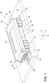
FIG. 1 is a perspective view generally illustrating portions of embodiments of a damper assembly according to teachings of the present disclosure. -
FIG. 1A is a side view generally illustrating portions of embodiments of a damper assembly according to teachings of the present disclosure. -
FIGS. 1B, 2A, and 2B are cross-sectional views generally illustrating portions of embodiments of dampers and brackets according to teachings of the present disclosure. -
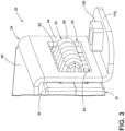
FIGS. 3 and4 are perspective views generally illustrating portions of embodiments of dampers and brackets according to teachings of the present disclosure. -
FIG. 5 is a cross-sectional view generally illustrating portions of embodiments of a damper and a bracket according to teachings of the present disclosure. -
FIGS. 6A and 6B are side views generally illustrating portions of embodiments of connecting members according to teachings of the present disclosure. -
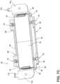
FIGS. 7A ,7B , and7C are perspective views generally illustrating portions of embodiments of dampers and brackets according to teachings of the present disclosure. -
FIGS. 8A and 8B are a perspective view and an exploded perspective view generally illustrating portions of embodiments of dampers and brackets according to teachings of the present disclosure. -
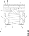
FIGS. 8C is a cross-sectional view generally illustrating portions of an embodiment of a damper and a bracket according to teachings of the present disclosure. -
FIGS. 9A and 9B are side views generally illustrating portions of embodiments of connecting members according to teachings of the present disclosure. -
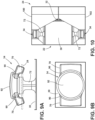
FIG. 10 is a side view generally illustrating portions embodiments of a damper and a bracket according to teachings of the present disclosure. -
FIG. 11 is a perspective view generally illustrating portions of embodiments of a damper and a bracket according to teachings of the present disclosure. -
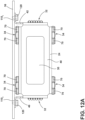
FIGS. 12A and12B are a side view and a perspective view generally illustrating portions of embodiments of dampers and brackets according to teachings of the present disclosure. -
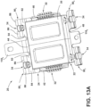
FIGS. 13A and13B are perspective views generally illustrating portions of embodiments of dampers and brackets according to teachings of the present disclosure. -
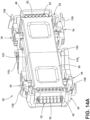
FIGS. 14A and14B are perspective views generally illustrating portions of embodiments of dampers and brackets according to teachings of the present disclosure. -
FIGS. 14C and14D are a side view and a top view generally illustrating portions of embodiments of dampers and brackets according to teachings of the present disclosure. -
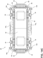
FIGS. 15A ,15B , and15C are perspective views generally illustrating portions of damper assemblies according to teachings of the present disclosure. -
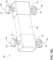
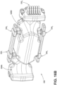
FIGS. 16A ,16B , and16C are perspective views generally illustrating portions of damper assemblies according to teachings of the present disclosure. - Reference will now be made in detail to embodiments of the present disclosure, examples of which are described herein and illustrated in the accompanying drawings. While the present disclosure will be described in conjunction with embodiments and/or examples, it will be understood that they are not intended to limit the present disclosure to these embodiments and/or examples. On the contrary, the present disclosure is intended to cover alternatives, modifications, and equivalents.
- Some dampers, such as dampers used in a vehicle environment, may use blunt contact between planar surfaces as a travel limitation. Travel limitations may be utilized to improve an overall durability of working rubber. Dampers contacting panels in a vehicle may include or be connected to felt/flock tape and/or rubber pads to reduce noise.
- In embodiments, such as generally illustrated in
FIGS. 1 ,1A, 1B, 2A ,2B ,3 ,4 , and5 , adamper assembly 20 may include adamper 22 but in any event according to the invention includes abracket 24. Adamper 22 may include a body ormass 30, one ormovement limiters 32, and/or one or more connectingmembers 34. Adamper 22 may be connected with abracket 24 via one or more connectingmembers 34 such that thebody 30 may move, at least to some degree, relative to the bracket 24 (e.g., in an X-direction, which may include fore and aft directions). Adamper 22 may include one or more of a variety of shapes, sizes, configurations, and/or materials. For example and without limitation, adamper 22 may include a resilient material (e.g., a rubber) and/or abody 30 may include a resilient material formed or disposed around a mass, such as a mass of metal. - With embodiments, a
bracket 24 may be configured for connecting adamper assembly 20 to a mounting component orsurface 36, such as a vehicle component or structure. Abracket 24 may include one or more of a variety of shapes, sizes, configurations, and/or materials. For example and without limitation, abracket 24 may include a metal, such as steel (see, e.g.,FIGS. 1 ,1A, and 1B ) and/or may include plastic (see, e.g.,FIGS. 2A and 2B ). Abracket 24 includes side walls, namely afirst side wall 40, asecond side wall 42, athird side wall 44, afourth side wall 46, and afifth side wall 48. Thesecond side wall 42, thethird side wall 44, thefourth side wall 46, and thefifth side wall 48 extend from the first side wall 40 (e.g., perpendicularly), such as to generally form a rectangular prism configuration. Abracket 24 may include anopen side 50 that may be disposed opposite thefirst side wall 40. Abracket 24 may include one ormore apertures 52 that may be configured to engage and/or at least partially receive a movement limiter. As generally illustrated inFIGS. 1 ,1A ,1B ,3 , and4 , anaperture 52 may, for example and without limitation, be disposed in and/or extend through thesecond side wall 42 and/or the fourth side wall 46 (e.g., at opposite sides of the bracket 24). With embodiments, abracket 24 may include one ormore recesses 54 that may, for example, be disposed or formed at an inner surface ofbracket 24, such as at inner surfaces of thesecond side wall 42 and/or the fourth side wall 46 (see, e.g.,FIGS. 2A, 2B , and5 ). - In embodiments, a
movement limiter 32 may be configured to restrict movement of thebody 30 relative to thebracket 24. Amovement limiter 32 restricts movement of thebody 30 toward thefirst side wall 40 and away from the first side wall 40 (e.g., fore and aft movement). In embodiments, amovement limiter 32 may impede or restrict movement in one or more other directions (e.g., in Z-directions), which may, with some examples, be parallel with a vertical direction), such as under large loads. Amovement limiter 32 extends from thebody 30 and may extend at least partially into anaperture 52 orrecess 54 of thebracket 24. For example and without limitation, amovement limiter 32 may extend into and through anaperture 52 of abracket 24. Amovement limiter 32 may include one or more of a variety of shapes, sizes, configurations, and/or materials. For example and without limitation, amovement limiter 32 may include a generally triangular configuration but in any event according to the invention includes a plurality ofribs 60 that may be spaced from each other, such as in a Z-direction (e.g., amovement limiter 32 may include a castellated configuration). A plurality ofribs 60 may include, for example only, six ribs. Theribs 60 may be disposed such that upon movement of the body 30 (e.g., in an X-direction), theribs 60 contact an inner surface or edge 62 of theaperture 52 orrecess 54 of thebracket 24 and restrict additional movement of thebody 30. - As generally illustrated in
FIG. 4 , in embodiments a distance D1 between amovement limiter 32 and theinner surface 62 of anaperture 52 orrecess 54 of abracket 24 may be less than a distance D2 between abody 30 of thedamper 22 and thebracket 24 such that themovement limiter 32 contacts theinner surface 62 of theaperture 52 orrecess 54 before thebody 30 contacts thebracket 24. - In embodiments, a movement limiter with
ribs 60 may reduce overall surface contact between thedamper 22 and thebracket 24, such as compared to a movement limiter without ribs, including movement limiters with planar contact portions. For example and without limitation, reducing surface contact may, inter alia, reduce noise produced via contact between thedamper 22 and the bracket, such as, for example, a slapping noise. With embodiments, amovement limiter 32 or a plurality ofmovement limiters 32 may be the only portions of adamper 22 that may contact abracket 24. In embodiments, the size of themovement limiter 32 may remain substantially the same and theaperture 52 of thebracket 24 may be modified to set a working travel distance (e.g., distance D1) of thedamper 22. - In embodiments, a
damper 22 includes a pair ofmovement limiters 32 that may be disposed at opposite ends of thebody 30 and may extend at least partially into correspondingapertures 52 orrecesses 54 at opposite sides (e.g., thesecond side wall 42 and the fourth side wall 46) of thebracket 24. - With some embodiments, dampers may be directly molded to a body/mass and a bracket, and a bonding agent may be applied to the bracket. Such molding may involve larger cavities or molds to accommodate the mass and the bracket. Some embodiments may use "pull through carrot" style components instead of molding the mass to the bracket. Pull through carrot embodiments may involve a post assembly step of cutting excess material once assembled, which may add complexity to assembly.
- In embodiments, such as generally illustrated in
FIGS. 1 ,4 ,5 ,6A ,6B ,7A ,7B ,8A ,8B , and8C , connectingmembers 34 may be configured to connect abody 30 with abracket 24. As generally illustrated inFIGS. 6A-7A , a connectingmember 34 may include one or more arms orwings 70 and/or aleg 72. Aleg 72 may extend from thebody 30 in a Z-direction (e.g., perpendicularly from the body 30) and/or may connect the one ormore arms 70 with thebody 30. Thearms 70 may extend in opposite directions from each other and/or perpendicularly to the leg 72 (e.g., may extend in Y-directions). Thearms 70 and theleg 72 may, for example, form a generally T-shaped or bow tie-shaped configuration. Adamper 22 may include, for example only, four connectingmembers 34 that may include two connectingmembers 34 extending from a first side (e.g., a top) of thebody 30 and two connectingmembers 34 extending from a second side (e.g., a bottom) of thebody 30. - In embodiments, such as generally illustrated in
FIGS. 7A-7C , abracket 24 may include one ormore retainers 80 that may correspond to the one or more connectingmembers 34. For example and without limitation, aretainer 80 may include forked configurations. Connecting a connectingmember 34 with thebracket 24 may include snapping or pulling thearms 70 over a forkedretainer 80 such that aleg 72 is disposed at least partially in the forkedretainer 80. Snapping or pulling thearms 70 over the forkedretainer 80 may include at least some deformation and/or stretching of theleg 72, such as in an axial direction of theleg 72, which may be a Z-direction. Deformation and/or stretching of theleg 72 may be only temporary during a connection process, and once connection is complete, theleg 72 may return to an initial state and/or may not be materially deformed, stretched, and/or stressed in a rest state (e.g., in an assembled configuration). For example and without limitation, in an assembled configuration, a connectingmember 34 may not under a material amount of tensile strain to impart major deformation and/or fatigue (e.g., aleg 72 may be stretched about 5% or less, which may not cause substantial/material fatigue). A connection process may include snapping one ormore movement limiters 32 into correspondingapertures 52, which may include at least some deformation of the movement limiters 32. Connecting adamper 22 with abracket 24 via the connectingmembers 34 may not involve any post assembly operations as the connectingmembers 34 may not include any excess portions to be removed. - In embodiments, a
retainer 80 may include afirst portion 82 and asecond portion 84 that may be spaced from thefirst portion 82. Thefirst portion 82 and thesecond portion 84 may be disposed in a fork-like configuration. A distance D3 between thefirst portion 82 and thesecond portion 84 may correspond to awidth 72W of aleg 72 of a corresponding connecting member 34 (see, e.g.,FIG. 7A ). Aretainer 80 may include one or more lip orflange portions 86 that may extend from afirst portion 82 and/or from asecond portion 84. The lip orflange portions 86 may extend away from thebody 30, such as in a Z-direction and/or in a direction parallel to an axial direction of theleg 72 of a corresponding connectingmember 34, which may be parallel to a Z-direction. Connecting adamper 22 with abracket 24 may include lifting/pulling arms of a connectingmember 34 outward beyond a lip orflange portion 86, sliding aleg 72 of the connectingmember 34 between thefirst portion 82 and thesecond portion 84, and/or releasing thearms 70 to rest on thefirst portion 82 and thesecond portion 84. - With some embodiments, dampers may be attached to upper and lower sections of a C-channel or cross member. A damper may be connected to a C-channel or cross member via upper and lower brackets, such as to accommodate or compensate for differences in attachment distances (e.g., if an attachment distance is on the low or high side of dimensional specifications). Some dampers may be directly bonded to an upper and lower bracket. If the attachment distance is not within a specified range, rubber legs of the damper may either be stretched or compressed while the damper is attached (and at rest) and/or during use. Such stretching or compression may cause durability issues or premature wear for the damper.
- With embodiments, such as generally illustrated in
FIG. 7C , a mounting portion, such as mountingportions tabs 112 that may have an L-shaped configuration.Tabs 112 may extend from a side of mountingportions component 36. - With embodiments, such as generally illustrated in
FIGS. 8A, 8B , and8C , adamper assembly 20 may include abracket 24 that may include afirst portion 100 and a second portion 102 (e.g., first and second halves). Adamper assembly 220 may include one ormore connectors first portion 100 with thesecond portion 102. Aconnector connector bracket 24 may includerecesses connectors first portion 100 andsecond portion 102 of thebracket 24 may cooperate to formrecesses first portion 100 andsecond portion 102 may each include about half ofrecesses - In embodiments, such as generally illustrated in
FIGS. 9A, 9B , and11 , a connectingmember 34 may be configured to transfer stress of aleg 72 of the connectingmember 34 to a different area or location, such as to thearms 70. For example and without limitation, anarm 70 may include a stress relief ortransfer portion 90. A stress relief ortransfer portion 90 may correspond to a portion of thearm 70 with a reduced thickness that may be configured for deflection under stress. Stress relieved or transferred via a stress relief ortransfer portion 90 may otherwise be experienced by a leg 72 (e.g.,arms 70 orstress relief portions 90 may be designed to flex or deform before theleg 72 flexes or deforms). - With embodiments, relocating or transferring stresses to a non-functioning feature (e.g., the arms) may improve durability and overall life of the
damper 22. The arms of the connectingmembers 34 may be angled (e.g., toward the body 30) and/or may act as a preload if thelegs 72 are in compression, which may improve durability of thelegs 72. Adamper 22 with stress relieving connectingmembers 34 may provide improved, such as, for example, if an attachment distance is outside of a nominal range on a high end or a low end (e.g., ±5 mm). - With embodiments, a connecting
member 34 may include a substantially round orcylindrical portion 92. The arms of a connectingmember 34 may extend from the round orcylindrical portion 92. The round orcylindrical portion 92 may be connected to theleg 72. - In embodiments, such as generally illustrated in
FIGS. 2A, 2B ,5 ,10 , and11 , abracket 24 may include afirst portion 100 and asecond portion 102. Thefirst portion 100 and thesecond portion 102 may be configured to move (e.g., translate or slide) relative to each other, such as if an attachment distance is greater than or less than a nominal/design distance. - With embodiments, such as generally illustrated in
FIGS. 1 ,1A ,3 ,4 ,7A ,7B , and7C , abracket 24 may include one or more mountingportions 110. A mountingportion 110 may be configured for connecting adamper assembly 20 and/or abracket 24 with a mountingcomponent 36, such as a portion of a vehicle (e.g., a vehicle seat structure). A mountingportion 110 may, for example and without limitation, include a threadedportion 120, such as nut welded to the mountingportion 110. A mountingportion 110 may extend from a side wall of a bracket, such as from asecond side wall 42 and/or from afourth side wall 46. A mounting portion (e.g., mountingportion 1101, 1102) may extend from an end of a side wall, such as generally illustrated inFIGS. 1 ,1A ,3 ,4 ,7A ,7B , and7C . For example and without limitation, a mountingportion 1101 may extend from an end of asecond side wall 42 and/or a mountingportion 1102 may extend from an end of afourth side wall 46, such as for a rear-side mounting configuration. - With embodiments, such as generally illustrated in
FIGS. 12A and12B , a mounting portion (e.g. mounting portion 1103) may extend from a side of asecond side wall 42 and/or a mounting portion (e.g. mounting portion 1104) may extend from side of afourth side wall 46, such as for an overhead mounting configuration. Mountingportions third side wall 44 and/or thefifth side wall 48. - In embodiments, such as generally illustrated in
FIGS. 13A and13B , a mounting portion 110s may extend from athird side wall 44 and/or a mountingportion 1106 may extend from afirst side wall 40. A mounting portion 110s may be disposed between (e.g., relative to a Y-direction) afirst retainer 801/a first connectingmember 34 and asecond retainer 802/a second connectingmember 34. Afirst retainer 801 and asecond retainer 802 may extend from a common side of thebracket 24. A pair of connecting members 34 (e.g., first and second connecting members) may extend from a common side of thedamper 22. Additionally or alternatively, a mountingportion 1106 may be disposed between athird retainer 803 and afourth retainer 804. A mounting portion 110s may extend at an angle (e.g., an oblique or right angle) relative tothird side wall 44. A mountingportion 110 may extend substantially parallel withfirst side wall 40. Mountingportions 110 may, for example and without limitation, include generally rectangular configurations. - With embodiments, such as generally illustrated in
FIGS. 14A ,14B ,14C , and14D , a mountingportion 1107 may extend from athird side wall 44 and/or a mountingportion 1108 may extend from afifth side wall 48. Mountingportions first side wall 40 of thebracket 24. A mountingportion third side wall 44 and/or a mountingportion fifth side wall 48. Mountingportions apertures 122 that may be configured to receive a fastener for connecting thebracket 24 with a mountingcomponent 36. - In embodiments, such as generally illustrated in
FIGS. 14A ,14B ,14C , and14D abracket 24 may include one or more clips 130 (e.g., flexible mounting clips). Aclip 130 may be configured to engage a mountingcomponent 36 to at least temporarily retain abracket 24 relative to the mountingcomponent 36 and/or to facilitate alignment of mountingportions 110 with the mountingcomponent 36. Aclip 130 may be flexible/resilient and/or may be configured to bend or flex into and/or out of engagement with a mountingcomponent 36. For example and without limitation, during a connection with a mountingcomponent 36, the one ormore clips 130 may initially flex (e.g., in a Y-direction and/or in a Z-direction) and/or may snap back and into engagement with the mountingcomponent 36. - With embodiments, such as generally illustrated in
FIGS. 15A ,15B , and15C , adamper assembly 220 may include adamper 222 but in any event according to the invention includes abracket 224. Adamper 222 may include connectingmembers 234 that may connect thedamper 222 with thebracket 224. A connectingmember 234 may include ahead 270 and/or aleg 272 that may connect thehead 270 with abody 230 of thedamper 222. Ahead 270 may include one or more of a variety of shapes, sizes, and/or configurations. For example and without limitation, ahead 270 may include a rectangular, square, and/or diamond-shaped configurations, among other configurations. With embodiments, ahead 270 may be disposed substantially perpendicular to aleg 272. - In embodiments, a
bracket 224 may include one ormore retainers 280 that may be configured to at least partially receive and/or retain connectingmember 234.Retainers 280 may be configured as recesses and/or chambers. Abracket 224 may include afirst portion 224A and asecond portion 224B. Thefirst portion 224A and thesecond portion 224B may cooperate to form or define one or more retainers 280 (e.g., eachportion members 234 and/orretainers 280 may be configured for connectingmembers 234 to be compressed, at least to some degree, within theretainers 280. For example and without limitation, one or more inner dimensions of aretainer 280 may be at least somewhat smaller than outer dimensions of ahead 270 of a connectingmember 234. A shape of aretainer 280 may correspond to the shape of ahead 270. Adamper assembly 220 may include one ormore connectors 290 that may connect thefirst portion 224A with thesecond portion 224B. Aconnector 290 may include one or more of a variety of shapes, sizes, and/or configurations. For example and without limitation, aconnector 290 may include a tube-shaped configuration, among other configurations. Adamper 222 includes movement limiters that may be configured in the same or a similar manner as movement limiters 32. Abracket 224 may include apertures and/or recesses that may correspond to the movement limiters and may be configured in the same or a similar manner asapertures 52 and/or recesses 54. Thefirst portion 224A with thesecond portion 224B may include correspondinglatch members 228 that may be configured for connecting thefirst portion 224A with thesecond portion 224B. - With embodiments, such as generally illustrated in
FIGS. 16A ,16B , and16C , adamper assembly 320 may include adamper 322 but in any event according to the invention includes abracket 324. Adamper 322 includes movement limiters (e.g.,movement limiters 3321, 3322) that may be configured to restrict movement of thedamper 322 relative to thebracket 324.Movement limiters damper 322 includes connecting members (e.g., connectingmembers damper 322 with thebracket 324. Adamper 322 may include one or more recesses (e.g., recesses 326A, 326B). Abracket 324 may include or more recesses (e.g., recesses 328A, 328B).Recesses posts headrest 364, such as of a vehicle seat.Recesses posts Recesses first movement limiter 3321 and connectingmembers second movement limiter 3322 and connectingmembers members members 3342, 3344) may be connected and/or formed together. With embodiments, abracket 324 may include one ormore retainers 380 that may be configured for connection with multiple connecting members (e.g., connectingmembers members 3342, 3344).
Claims (11)
- A damper assembly (20, 220, 320), comprising:a bracket (24, 224, 324);a body (30, 230);a movement limiter (32, 3321, 3322) extending from the body (30, 230), the movement limiter (32, 3321, 3322) including a plurality of ribs (60) configured for contacting an inner surface of an aperture (52) of the bracket (24, 224, 324) to limit movement of the body (30, 230) relative to the bracket (24, 224, 324);a plurality of connecting members (34, 234, 3341, 3342, 3343, 3344) extending from the body (30, 230), the plurality of connecting members (34, 234, 3341, 3342, 3343, 3344) connecting the body (30, 230) with the bracket (24, 224, 324); anda second movement limiter (32, 3321, 3322), wherein the movement limiter (32, 3321, 3322) and the second movement limiter (32, 3321, 3322) extend from opposite sides of the body (30, 230), wherein the bracket (24, 224, 324) includes a first side wall (40), a second side wall (42), a third side wall (44), a fourth side wall (46), and a fifth side wall (48); the second side wall (42), the third side wall (44), the fourth side wall (46), and the fifth side wall (48) extend from the first side wall (40); the aperture (52) is disposed in one of the second side wall (42), the third side wall (44), the fourth side wall (46), and the fifth side wall (48); and the movement limiters (32, 3321, 3322) are configured to restrict movement of the body (30, 230) toward the first side wall (40) and away from the first side wall (40).
- The damper assembly (20, 220, 320) of claim 1, wherein the plurality of connecting members (34, 234, 3341, 3342, 3343, 3344) include a resilient material.
- The damper assembly (20, 220, 320) of claim 1, wherein the movement limiter (32, 3321, 3322) includes a substantially triangular configuration, and/or wherein the movement limiter (32, 3321, 3322) is configured to deform during insertion of the body (30, 230) into the bracket (24, 224, 324), and/or wherein the movement limiter (32, 3321, 3322) extends through the aperture (52).
- The damper assembly (20, 220, 320) of claim 1, wherein the plurality of connecting members (34, 234, 3341, 3342, 3343, 3344) includes four connecting members (34, 234, 3341, 3342, 3343, 3344).
- The damper assembly (20, 220, 320) of claim 1, wherein a first connecting member of the plurality of connecting members (34, 234, 3341, 3342, 3343, 3344) extends from a first side of the body (30, 230), a second connecting member of the plurality of connecting members (34, 234, 3341, 3342, 3343, 3344) extends from a second side of the body (30, 230), and the first side is opposite the second side, wherein preferably the movement limiter (32, 3321, 3322) extends from a third side of the body (30, 230), and the third side is disposed substantially perpendicular relative to the first side and the second side.
- The damper assembly (20, 220, 320) of claim 1, wherein at least one of the plurality of connecting members (34, 234, 3341, 3342, 3343, 3344) includes a T-shaped configuration.
- The damper assembly (20, 220, 320) of claim 1, wherein, in an assembled configuration, the plurality of connecting members (34, 234, 3341, 3342, 3343, 3344) are not under a material amount of tensile strain to impart major deformation and/or fatigue.
- The damper assembly (20, 220, 320) of claim 1, wherein the body (30, 230) is not in contact with the bracket (24, 224, 324).
- The damper assembly (20, 220, 320) of claim 1, wherein the bracket (24, 224, 324) includes one or more clips configured to at least temporarily connect the bracket (24, 224, 324) with a mounting component (36), and the bracket (24, 224, 324) includes one or more mounting portions (110) configured to connect the bracket (24, 224, 324) with said mounting component (36).
- The damper assembly (20, 220, 320) of claim 1, wherein the movement limiter (32, 3321, 3322) extends in a Y-direction, the bracket (24, 224, 324) includes a mounting portion (110) that extends beyond the movement limiter (32, 3321, 3322) in the Y-direction, and the mounting portion (110) includes a threaded portion (120).
- The damper assembly (20, 220, 320) of claim 1, wherein the plurality of connecting members (34, 234, 3341, 3342, 3343, 3344) includes a first connecting member and a second connecting member that extend from a common side of the bracket (24, 224, 324), and the bracket (24, 224, 324) includes a mounting portion (110) disposed between the first connecting member and the second connecting member relative to a Y-direction, wherein preferably the bracket (24, 224, 324) includes a plurality of flexible mounting clips (130).
Applications Claiming Priority (2)
| Application Number | Priority Date | Filing Date | Title |
|---|---|---|---|
| US201762542853P | 2017-08-09 | 2017-08-09 | |
| US16/010,792 US10738853B2 (en) | 2017-08-09 | 2018-06-18 | Damper and assembly |
Publications (3)
| Publication Number | Publication Date |
|---|---|
| EP3441639A1 EP3441639A1 (en) | 2019-02-13 |
| EP3441639C0 EP3441639C0 (en) | 2025-04-30 |
| EP3441639B1 true EP3441639B1 (en) | 2025-04-30 |
Family
ID=63142999
Family Applications (1)
| Application Number | Title | Priority Date | Filing Date |
|---|---|---|---|
| EP18186911.6A Active EP3441639B1 (en) | 2017-08-09 | 2018-08-01 | Damper assembly and damper therefor |
Country Status (7)
| Country | Link |
|---|---|
| US (1) | US10738853B2 (en) |
| EP (1) | EP3441639B1 (en) |
| JP (1) | JP6954872B2 (en) |
| KR (1) | KR102502137B1 (en) |
| CN (1) | CN109386565B (en) |
| MX (1) | MX2018009664A (en) |
| PL (1) | PL3441639T3 (en) |
Families Citing this family (3)
| Publication number | Priority date | Publication date | Assignee | Title |
|---|---|---|---|---|
| DE102016115782B4 (en) * | 2016-08-25 | 2019-06-19 | Vibracoustic Gmbh | vibration absorber |
| JP7422623B2 (en) * | 2020-07-22 | 2024-01-26 | Toyo Tire株式会社 | Dynamic damper mounting structure |
| US11292375B1 (en) | 2020-11-10 | 2022-04-05 | Ford Global Technologies, Llc | Headrest assembly |
Citations (4)
| Publication number | Priority date | Publication date | Assignee | Title |
|---|---|---|---|---|
| US6991077B2 (en) * | 2001-09-28 | 2006-01-31 | Tokai Rubber Industries, Ltd. | Vibration damping device |
| US7264097B2 (en) * | 2003-07-17 | 2007-09-04 | Tokai Rubber Industries, Ltd. | Dynamic damper |
| US20160102726A1 (en) * | 2014-10-10 | 2016-04-14 | Nbjx Usa, Inc. | Mass damper |
| US20160339817A1 (en) * | 2015-05-19 | 2016-11-24 | Toyota Boshoku Kabushiki Kaisha | Vehicle seat |
Family Cites Families (13)
| Publication number | Priority date | Publication date | Assignee | Title |
|---|---|---|---|---|
| JP2599059B2 (en) * | 1991-11-25 | 1997-04-09 | 東海ゴム工業株式会社 | Dynamic damper for hollow drive shaft |
| JP3985732B2 (en) | 2003-05-30 | 2007-10-03 | 東海ゴム工業株式会社 | Dynamic damper |
| US7410039B2 (en) * | 2005-02-04 | 2008-08-12 | Asm Assembly Automation Ltd. | Tunable vibration absorption device |
| JP2007078159A (en) | 2005-09-16 | 2007-03-29 | Tokai Rubber Ind Ltd | Dynamic damper |
| DE202006010876U1 (en) * | 2006-07-10 | 2006-09-28 | Takata-Petri Ag | Energy absorber for motor vehicle seat or child seat, has covering of flexible material wrapped around foam core |
| JP4857216B2 (en) | 2007-08-07 | 2012-01-18 | 倉敷化工株式会社 | Dynamic damper |
| EP2871093B1 (en) | 2012-07-06 | 2018-11-14 | TS Tech Co., Ltd. | Seat device for vehicle |
| JP6110609B2 (en) * | 2012-07-06 | 2017-04-05 | テイ・エス テック株式会社 | Vehicle seat device |
| JP6166581B2 (en) * | 2013-04-25 | 2017-07-19 | テイ・エス テック株式会社 | Vehicle seat device |
| DE102014206232A1 (en) * | 2014-04-02 | 2015-10-08 | Volkswagen Aktiengesellschaft | Vibration damper for a vehicle seat, vehicle seat and motor vehicle |
| DE102014018212A1 (en) * | 2014-12-09 | 2016-06-09 | Süddeutsche Gelenkscheibenfabrik GmbH & Co. KG | Device for damping vibrations |
| FR3048474B1 (en) | 2016-03-04 | 2018-04-20 | Cooper Standard France | DEVICE FOR DAMPING VIBRATIONS BETWEEN A FIRST VIBRATING ELEMENT AND A SECOND ELEMENT |
| KR102115200B1 (en) * | 2018-05-28 | 2020-05-26 | 주식회사 대흥알앤티 | Dynamic damper |
-
2018
- 2018-06-18 US US16/010,792 patent/US10738853B2/en active Active
- 2018-08-01 EP EP18186911.6A patent/EP3441639B1/en active Active
- 2018-08-01 PL PL18186911.6T patent/PL3441639T3/en unknown
- 2018-08-06 KR KR1020180091299A patent/KR102502137B1/en active Active
- 2018-08-08 JP JP2018149498A patent/JP6954872B2/en active Active
- 2018-08-08 CN CN201810896345.8A patent/CN109386565B/en active Active
- 2018-08-08 MX MX2018009664A patent/MX2018009664A/en unknown
Patent Citations (4)
| Publication number | Priority date | Publication date | Assignee | Title |
|---|---|---|---|---|
| US6991077B2 (en) * | 2001-09-28 | 2006-01-31 | Tokai Rubber Industries, Ltd. | Vibration damping device |
| US7264097B2 (en) * | 2003-07-17 | 2007-09-04 | Tokai Rubber Industries, Ltd. | Dynamic damper |
| US20160102726A1 (en) * | 2014-10-10 | 2016-04-14 | Nbjx Usa, Inc. | Mass damper |
| US20160339817A1 (en) * | 2015-05-19 | 2016-11-24 | Toyota Boshoku Kabushiki Kaisha | Vehicle seat |
Also Published As
| Publication number | Publication date |
|---|---|
| JP2019032081A (en) | 2019-02-28 |
| EP3441639C0 (en) | 2025-04-30 |
| KR102502137B1 (en) | 2023-02-21 |
| PL3441639T3 (en) | 2025-10-27 |
| MX2018009664A (en) | 2019-02-12 |
| JP6954872B2 (en) | 2021-10-27 |
| CN109386565B (en) | 2022-04-12 |
| EP3441639A1 (en) | 2019-02-13 |
| KR20190016913A (en) | 2019-02-19 |
| CN109386565A (en) | 2019-02-26 |
| US10738853B2 (en) | 2020-08-11 |
| US20190048960A1 (en) | 2019-02-14 |
Similar Documents
| Publication | Publication Date | Title |
|---|---|---|
| US8430382B2 (en) | Stopper structure of torque rod | |
| JP5798596B2 (en) | Vibration isolator | |
| US9518628B2 (en) | Tubular vibration-damping device | |
| EP2750906B1 (en) | A vibroisolating device with a nonlinear force vs. displacement characteristic and a motor vehicle suspension system comprising such vibroisolating device | |
| CN104937303B (en) | Cylindrical vibration isolating device | |
| EP3203108A1 (en) | Vibration isolation device | |
| CN105378330B (en) | Vibration isolation device | |
| US10738853B2 (en) | Damper and assembly | |
| CN111448403A (en) | Cylindrical vibration isolator | |
| JP6595371B2 (en) | Vibration isolator | |
| CN104912997B (en) | Vibration isolation device | |
| US9394958B2 (en) | Vibration damping device | |
| JP2005036845A (en) | Dynamic damper | |
| US20130168907A1 (en) | Vibration isolator | |
| JP3893977B2 (en) | Vibration isolator | |
| JP4304054B2 (en) | Cylindrical bush | |
| JP2020060222A (en) | Cylindrical vibration controller | |
| JPH0728434Y2 (en) | Exhaust pipe anti-vibration support | |
| KR102679744B1 (en) | Safe ring for pressure regulating valve to improve assemblyability | |
| CN220726950U (en) | Load self-adaptive elastic vibration isolator | |
| US20070102617A1 (en) | Powertrain mount | |
| JP2017067156A (en) | Vibration isolation device | |
| JP2008507664A (en) | Multipurpose powertrain mount with integrated restrictor | |
| CN117108664A (en) | Load self-adaptive elastic vibration isolator | |
| JP2023070307A (en) | torque rod |
Legal Events
| Date | Code | Title | Description |
|---|---|---|---|
| PUAI | Public reference made under article 153(3) epc to a published international application that has entered the european phase |
Free format text: ORIGINAL CODE: 0009012 |
|
| STAA | Information on the status of an ep patent application or granted ep patent |
Free format text: STATUS: THE APPLICATION HAS BEEN PUBLISHED |
|
| AK | Designated contracting states |
Kind code of ref document: A1 Designated state(s): AL AT BE BG CH CY CZ DE DK EE ES FI FR GB GR HR HU IE IS IT LI LT LU LV MC MK MT NL NO PL PT RO RS SE SI SK SM TR |
|
| AX | Request for extension of the european patent |
Extension state: BA ME |
|
| STAA | Information on the status of an ep patent application or granted ep patent |
Free format text: STATUS: REQUEST FOR EXAMINATION WAS MADE |
|
| 17P | Request for examination filed |
Effective date: 20190708 |
|
| RBV | Designated contracting states (corrected) |
Designated state(s): AL AT BE BG CH CY CZ DE DK EE ES FI FR GB GR HR HU IE IS IT LI LT LU LV MC MK MT NL NO PL PT RO RS SE SI SK SM TR |
|
| STAA | Information on the status of an ep patent application or granted ep patent |
Free format text: STATUS: EXAMINATION IS IN PROGRESS |
|
| 17Q | First examination report despatched |
Effective date: 20200904 |
|
| REG | Reference to a national code |
Ref country code: DE Ipc: B60N0002500000 Ref country code: DE Ref legal event code: R079 Ref document number: 602018081464 Country of ref document: DE Free format text: PREVIOUS MAIN CLASS: F16F0007104000 Ipc: B60N0002500000 |
|
| GRAP | Despatch of communication of intention to grant a patent |
Free format text: ORIGINAL CODE: EPIDOSNIGR1 |
|
| STAA | Information on the status of an ep patent application or granted ep patent |
Free format text: STATUS: GRANT OF PATENT IS INTENDED |
|
| RIC1 | Information provided on ipc code assigned before grant |
Ipc: F16F 7/104 20060101ALI20240917BHEP Ipc: F16F 7/108 20060101ALI20240917BHEP Ipc: B60N 2/50 20060101AFI20240917BHEP |
|
| INTG | Intention to grant announced |
Effective date: 20241002 |
|
| GRAJ | Information related to disapproval of communication of intention to grant by the applicant or resumption of examination proceedings by the epo deleted |
Free format text: ORIGINAL CODE: EPIDOSDIGR1 |
|
| STAA | Information on the status of an ep patent application or granted ep patent |
Free format text: STATUS: EXAMINATION IS IN PROGRESS |
|
| GRAP | Despatch of communication of intention to grant a patent |
Free format text: ORIGINAL CODE: EPIDOSNIGR1 |
|
| STAA | Information on the status of an ep patent application or granted ep patent |
Free format text: STATUS: GRANT OF PATENT IS INTENDED |
|
| INTC | Intention to grant announced (deleted) | ||
| INTG | Intention to grant announced |
Effective date: 20250213 |
|
| GRAS | Grant fee paid |
Free format text: ORIGINAL CODE: EPIDOSNIGR3 |
|
| GRAA | (expected) grant |
Free format text: ORIGINAL CODE: 0009210 |
|
| STAA | Information on the status of an ep patent application or granted ep patent |
Free format text: STATUS: THE PATENT HAS BEEN GRANTED |
|
| AK | Designated contracting states |
Kind code of ref document: B1 Designated state(s): AL AT BE BG CH CY CZ DE DK EE ES FI FR GB GR HR HU IE IS IT LI LT LU LV MC MK MT NL NO PL PT RO RS SE SI SK SM TR |
|
| REG | Reference to a national code |
Ref country code: CH Ref legal event code: EP Ref country code: GB Ref legal event code: FG4D |
|
| REG | Reference to a national code |
Ref country code: DE Ref legal event code: R096 Ref document number: 602018081464 Country of ref document: DE |
|
| REG | Reference to a national code |
Ref country code: IE Ref legal event code: FG4D |
|
| U01 | Request for unitary effect filed |
Effective date: 20250530 |
|
| U07 | Unitary effect registered |
Designated state(s): AT BE BG DE DK EE FI FR IT LT LU LV MT NL PT RO SE SI Effective date: 20250610 |
|
| U20 | Renewal fee for the european patent with unitary effect paid |
Year of fee payment: 8 Effective date: 20250827 |
|
| PG25 | Lapsed in a contracting state [announced via postgrant information from national office to epo] |
Ref country code: ES Free format text: LAPSE BECAUSE OF FAILURE TO SUBMIT A TRANSLATION OF THE DESCRIPTION OR TO PAY THE FEE WITHIN THE PRESCRIBED TIME-LIMIT Effective date: 20250430 |
|
| PG25 | Lapsed in a contracting state [announced via postgrant information from national office to epo] |
Ref country code: NO Free format text: LAPSE BECAUSE OF FAILURE TO SUBMIT A TRANSLATION OF THE DESCRIPTION OR TO PAY THE FEE WITHIN THE PRESCRIBED TIME-LIMIT Effective date: 20250730 Ref country code: GR Free format text: LAPSE BECAUSE OF FAILURE TO SUBMIT A TRANSLATION OF THE DESCRIPTION OR TO PAY THE FEE WITHIN THE PRESCRIBED TIME-LIMIT Effective date: 20250731 |
|
| PGFP | Annual fee paid to national office [announced via postgrant information from national office to epo] |
Ref country code: TR Payment date: 20250728 Year of fee payment: 8 |
|
| PGFP | Annual fee paid to national office [announced via postgrant information from national office to epo] |
Ref country code: GB Payment date: 20250821 Year of fee payment: 8 |
|
| PG25 | Lapsed in a contracting state [announced via postgrant information from national office to epo] |
Ref country code: HR Free format text: LAPSE BECAUSE OF FAILURE TO SUBMIT A TRANSLATION OF THE DESCRIPTION OR TO PAY THE FEE WITHIN THE PRESCRIBED TIME-LIMIT Effective date: 20250430 |
|
| PG25 | Lapsed in a contracting state [announced via postgrant information from national office to epo] |
Ref country code: RS Free format text: LAPSE BECAUSE OF FAILURE TO SUBMIT A TRANSLATION OF THE DESCRIPTION OR TO PAY THE FEE WITHIN THE PRESCRIBED TIME-LIMIT Effective date: 20250731 |
|
| PG25 | Lapsed in a contracting state [announced via postgrant information from national office to epo] |
Ref country code: IS Free format text: LAPSE BECAUSE OF FAILURE TO SUBMIT A TRANSLATION OF THE DESCRIPTION OR TO PAY THE FEE WITHIN THE PRESCRIBED TIME-LIMIT Effective date: 20250830 |
|
| PG25 | Lapsed in a contracting state [announced via postgrant information from national office to epo] |
Ref country code: SM Free format text: LAPSE BECAUSE OF FAILURE TO SUBMIT A TRANSLATION OF THE DESCRIPTION OR TO PAY THE FEE WITHIN THE PRESCRIBED TIME-LIMIT Effective date: 20250430 |
|
| PG25 | Lapsed in a contracting state [announced via postgrant information from national office to epo] |
Ref country code: CZ Free format text: LAPSE BECAUSE OF FAILURE TO SUBMIT A TRANSLATION OF THE DESCRIPTION OR TO PAY THE FEE WITHIN THE PRESCRIBED TIME-LIMIT Effective date: 20250430 |
|
| PGFP | Annual fee paid to national office [announced via postgrant information from national office to epo] |
Ref country code: PL Payment date: 20250725 Year of fee payment: 8 |
|
| PG25 | Lapsed in a contracting state [announced via postgrant information from national office to epo] |
Ref country code: SK Free format text: LAPSE BECAUSE OF FAILURE TO SUBMIT A TRANSLATION OF THE DESCRIPTION OR TO PAY THE FEE WITHIN THE PRESCRIBED TIME-LIMIT Effective date: 20250430 |
|
| PLBE | No opposition filed within time limit |
Free format text: ORIGINAL CODE: 0009261 |
|
| STAA | Information on the status of an ep patent application or granted ep patent |
Free format text: STATUS: NO OPPOSITION FILED WITHIN TIME LIMIT |
|
| REG | Reference to a national code |
Ref country code: CH Ref legal event code: L10 Free format text: ST27 STATUS EVENT CODE: U-0-0-L10-L00 (AS PROVIDED BY THE NATIONAL OFFICE) Effective date: 20260311 |
|
| REG | Reference to a national code |
Ref country code: CH Ref legal event code: H13 Free format text: ST27 STATUS EVENT CODE: U-0-0-H10-H13 (AS PROVIDED BY THE NATIONAL OFFICE) Effective date: 20260324 |
|
| PG25 | Lapsed in a contracting state [announced via postgrant information from national office to epo] |
Ref country code: MC Free format text: LAPSE BECAUSE OF FAILURE TO SUBMIT A TRANSLATION OF THE DESCRIPTION OR TO PAY THE FEE WITHIN THE PRESCRIBED TIME-LIMIT Effective date: 20250430 |
|
| 26N | No opposition filed |
Effective date: 20260202 |
|
| PG25 | Lapsed in a contracting state [announced via postgrant information from national office to epo] |
Ref country code: CH Free format text: LAPSE BECAUSE OF NON-PAYMENT OF DUE FEES Effective date: 20250831 |