EP3441351A1 - Cart assembly for use with a work piece and methods of use - Google Patents
Cart assembly for use with a work piece and methods of use Download PDFInfo
- Publication number
- EP3441351A1 EP3441351A1 EP18183816.0A EP18183816A EP3441351A1 EP 3441351 A1 EP3441351 A1 EP 3441351A1 EP 18183816 A EP18183816 A EP 18183816A EP 3441351 A1 EP3441351 A1 EP 3441351A1
- Authority
- EP
- European Patent Office
- Prior art keywords
- trolley
- base
- work piece
- work
- floor
- Prior art date
- Legal status (The legal status is an assumption and is not a legal conclusion. Google has not performed a legal analysis and makes no representation as to the accuracy of the status listed.)
- Granted
Links
Images



Classifications
-
- B—PERFORMING OPERATIONS; TRANSPORTING
- B66—HOISTING; LIFTING; HAULING
- B66F—HOISTING, LIFTING, HAULING OR PUSHING, NOT OTHERWISE PROVIDED FOR, e.g. DEVICES WHICH APPLY A LIFTING OR PUSHING FORCE DIRECTLY TO THE SURFACE OF A LOAD
- B66F7/00—Lifting frames, e.g. for lifting vehicles; Platform lifts
- B66F7/06—Lifting frames, e.g. for lifting vehicles; Platform lifts with platforms supported by levers for vertical movement
- B66F7/065—Scissor linkages, i.e. X-configuration
- B66F7/0683—Scissor linkage plus tilting action
-
- B—PERFORMING OPERATIONS; TRANSPORTING
- B60—VEHICLES IN GENERAL
- B60P—VEHICLES ADAPTED FOR LOAD TRANSPORTATION OR TO TRANSPORT, TO CARRY, OR TO COMPRISE SPECIAL LOADS OR OBJECTS
- B60P1/00—Vehicles predominantly for transporting loads and modified to facilitate loading, consolidating the load, or unloading
- B60P1/02—Vehicles predominantly for transporting loads and modified to facilitate loading, consolidating the load, or unloading with parallel up-and-down movement of load supporting or containing element
-
- B—PERFORMING OPERATIONS; TRANSPORTING
- B23—MACHINE TOOLS; METAL-WORKING NOT OTHERWISE PROVIDED FOR
- B23P—METAL-WORKING NOT OTHERWISE PROVIDED FOR; COMBINED OPERATIONS; UNIVERSAL MACHINE TOOLS
- B23P21/00—Machines for assembling a multiplicity of different parts to compose units, with or without preceding or subsequent working of such parts, e.g. with program control
- B23P21/002—Machines for assembling a multiplicity of different parts to compose units, with or without preceding or subsequent working of such parts, e.g. with program control the units stationary whilst being composed
-
- B—PERFORMING OPERATIONS; TRANSPORTING
- B23—MACHINE TOOLS; METAL-WORKING NOT OTHERWISE PROVIDED FOR
- B23P—METAL-WORKING NOT OTHERWISE PROVIDED FOR; COMBINED OPERATIONS; UNIVERSAL MACHINE TOOLS
- B23P19/00—Machines for simply fitting together or separating metal parts or objects, or metal and non-metal parts, whether or not involving some deformation; Tools or devices therefor so far as not provided for in other classes
- B23P19/008—Machines for simply fitting together or separating metal parts or objects, or metal and non-metal parts, whether or not involving some deformation; Tools or devices therefor so far as not provided for in other classes the parts being continuously transported through the machine during assembling or disassembling
-
- B—PERFORMING OPERATIONS; TRANSPORTING
- B60—VEHICLES IN GENERAL
- B60P—VEHICLES ADAPTED FOR LOAD TRANSPORTATION OR TO TRANSPORT, TO CARRY, OR TO COMPRISE SPECIAL LOADS OR OBJECTS
- B60P1/00—Vehicles predominantly for transporting loads and modified to facilitate loading, consolidating the load, or unloading
- B60P1/04—Vehicles predominantly for transporting loads and modified to facilitate loading, consolidating the load, or unloading with a tipping movement of load-transporting element
Definitions
- the present disclosure relates generally to the field an assembly for moving and manipulating a work piece during a manufacturing process. More specifically, the present disclosure is directed to methods and apparatuses for transporting a work piece along an assembly line, and for adjusting vertical and angular orientations of the work piece to provide access to different sections of the work piece during assembly.
- the manufacturing process for many items includes assembly along an assembly line.
- An assembly line is used for a wide variety of items, including but not limited to aircraft, automobiles, household appliances, and electronic goods.
- the assembly line features a series of work stations that are each configured to perform one or more steps of the overall assembly process.
- the work stations are equipped with tools for adding components to the work piece.
- the work piece may start as a single component or the basic framework of the item.
- the work piece is further assembled and begins to resemble the final item.
- the end of the assembly line the work piece is either complete or ready for additional manufacturing steps at a different assembly process.
- a household appliance may be complete and ready for shipment to a customer at the end of the assembly line.
- a component of an aircraft such as an interior component, may be completed at the end of the assembly line and then moved for subsequent assembly into the larger overall aircraft.
- the positioning includes elevating the work piece to various heights above the work floor and/or orienting the work piece at different angular positions relative to the work floor. This may also include accessing the different sections and sides of the work piece (e.g., front-and-back, top-and-bottom, left-and-right sides).
- the size and/or weight of the work piece often makes it difficult or impossible for a worker to physically lift and manipulate the work piece. This is particularly true in later work stations along the assembly line when the numerous components have already been added to the work piece and it begins to resemble its final configuration. Further, the worker is not able to handle the work piece because they are also handling tools and components needed for assembly.
- aspects of the present disclosure comprise cart assemblies configured to support and position a work piece during an assembly process.
- the cart assemblies are configured to position the work piece at different elevational heights and angular orientations relative to a work floor.
- Methods of receiving and positioning the work pieces with a cart assembly are also disclosed.
- An aspect of the present disclosure is directed to a cart assembly configured to move a work piece about a work floor.
- the cart assembly includes a base with a top side and a bottom side spaced from the top side. The bottom side configured to be supported on the work floor.
- a table is positioned on the top side of the base and includes a first end, a second end spaced from the first end, a pivot disposed towards the first end, and a work surface that extends between the first and second ends and configured to support the work piece.
- the table is pivotally mounted to move about the pivot between a horizontal position and a vertical position.
- a tilt mechanism is coupled to the table and configured to rotate the table about the pivot between the horizontal position and the vertical position.
- a lift mechanism is disposed between the base and the table and is configured to move the table relative to the base between a lowered position defining a first distance above the work floor and a raised position defining a second distance above the work floor that is greater than the first distance.
- a trolley that includes wheels is configured to be supported on the work floor. The trolley is connected to the base and horizontally movable relative to the base along the work floor between a retracted position and an extended position. In the retracted position, the trolley is vertically overlapped by the first end of the table and in the extended position the trolley is horizontally spaced away from the first end of the table.
- the cart assembly includes at least one slide that connects the trolley to the base.
- the at least one slide is configured to prevent the trolley from rotating relative to the base.
- the trolley is detachable from the at least one slide to remove the trolley from the base.
- the trolley also includes a carousel operatively connected to the wheels and configured to rotate relative to the wheels of the trolley.
- the trolley includes a pin that extends outward from the carousel and is sized to engage with the work piece.
- the table is parallel to the base when in the horizontal position and perpendicular to the base when in the vertical position.
- the cart assembly includes a processing circuit communicatively connected to the lift mechanism and the tilt mechanism, a drive train to drive the base along the work floor, and a wireless transceiver operatively connected to the processing circuit and configured to wirelessly communicate with a remote source to remotely control the drive train, the tilt mechanism, and the lift mechanism.
- the cart assembly also includes a sensing circuit operatively connected to the processing circuit with the sensing circuit configured to detect an object within a physical envelope around the cart assembly and to signal the processing circuit to prevent movement of the cart assembly when the object is detected.
- a further aspect is directed to a cart assembly configured to move a work piece about a work floor.
- the cart assembly includes a base with a top side and a bottom side spaced from the top side with the bottom side configured to be supported on the work floor.
- a table is positioned on the top side of the base and has a pivot and presents a work surface configured to support the work piece.
- a lift mechanism is disposed between the base and the table and is configured to move the table relative to the base between a lowered position and a raised position.
- a tilt mechanism is connected to the table and configured to rotate the table about the pivot between a horizontal position and a vertical position.
- a trolley is configured to be supported on the work floor.
- the trolley is connected to the base and horizontally movable along the work floor relative to the base between a retracted position and an extended position.
- the cart assembly is movable between first, second, third, fourth, and fifth positions. In the first position the table is in the lowered and horizontal positions and the trolley is in the retracted position. In the second position the table is in the raised and horizontal positions and the trolley is in the retracted position. In the third position the table is in the raised and vertical positions and the trolley is in the retracted position. In the fourth position the table is in the lowered and vertical positions and the trolley is in the retracted position. In the fifth position the table is in the vertical position and the trolley is in the extended position.
- the lift mechanism includes a scissor lift with first and second arms with each of the arms having a first end connected to the base and a second end connected to the table.
- the cart assembly includes an adapter plate configured to be attached to the work piece to secure the work piece to the trolley.
- the cart assembly includes at least one slide that connects the trolley to the base with the at least one slide configured to prevent the trolley from rotating relative to the base and to locate the trolley between the extended and retracted positions.
- the trolley includes wheels to move along the work floor and also a carousel mounted to the wheels and that rotates relative to the wheels.
- the cart assembly includes a processing circuit communicatively connected to the lift mechanism and the tilt mechanism, a drive train to drive the base along the work floor, and a wireless transceiver operatively connected to the processing circuit and configured to wirelessly communicate with a remote source to remotely control the lift mechanism and the tilt mechanism to move the cart assembly between the first, second, third, fourth, and fifth positions.
- a further aspect is directed to a method of using a cart assembly to move a work piece about a work floor.
- the method includes: supporting the work piece with a table with the table attached to a base that is positioned on the work floor; positioning the table and the work piece in a lowered position a first distance from the work floor and with the table and the work piece in a horizontal position; raising the table away from the work floor to a raised position while the work piece is supported on the table and the base is on the work floor and the work piece is in the horizontal position; rotating the table and positioning the work piece transverse to the work floor while the work piece is supported on the table and the base is on the work floor and the table is in the raised position; positioning the work piece vertically over a trolley that is on the work floor and that is attached to base; lowering the table towards the work floor and positioning the work piece onto the trolley while the trolley is on the floor and is attached to the base while the work piece is supported on the table and the base is on the work floor; supporting the work piece on the trolley and removing the
- the method includes supporting the work piece on a shelf of an elbow member that is attached to and that extends outward from the table while the table is in the vertical position.
- the method includes simultaneously moving the base along the work floor while rotating and raising the table.
- the method includes comprising remotely rotating and raising the table.
- the method includes rotating the table 90° between the horizontal position and a vertical position.
- the method includes detaching the trolley from the base while the trolley is supporting the work piece.
- the present disclosure is directed to a cart assembly for positioning a work piece during manufacturing.
- the cart assembly includes a table with a work surface configured to support the work piece.
- the table is connected to a base that is movable along a work floor, and a lift mechanism that elevates the table above the work floor.
- a tilt mechanism provides for adjusting an angle of the table relative to the work floor.
- the lift and tilt mechanisms may be used separately or simultaneously to adjust the positioning of the table as needed.
- the cart assembly also includes a trolley.
- the trolley is configured to receive and support the work piece away from the base. This provides for a worker to access additional sections of the work piece during assembly.
- FIG. 1 illustrates a cart assembly 10 that is positioned on a work floor 110.
- the cart assembly 10 includes a base 20 and a table 30.
- Lift and tilt mechanisms 40, 50 are configured to adjust the elevation and angular positions of the table 30 relative to the work floor 110.
- a trolley 60 is connected to the base 20 and movable relative to the base 20 along the work floor 110.
- a work piece (not illustrated) may be moved from the table to the trolley 60. The trolley 60 may then be moved away from the base 20 to position the work piece 100 at additional positions to provide further accessibility for a worker.
- the base 20 forms the foundation of the cart assembly 10. As illustrated in Figures 1 and 2 , the base 20 includes an elongated length L with a top side 23 and a bottom side 24. Wheels 22 extend from the bottom side 24 to contact the work floor 110 and provide for movement of the cart assembly 10 along the work floor 110. The wheels 22 are configured to provide for movement in various directions about the work floor.
- the base 20 may also include a motor 29 and drivetrain that deliver power to one or more of the wheels 22 for propelling the cart assembly 10 around the work floor 110. In one design, the motor 29 is an electric motor, with other designs including other sources of power. In another design, the cart assembly 10 does not include a motor and drivetrain and relies upon the one or more workers for movement along the work floor 110.
- the table 30 is positioned at the top side 23 of the base 20.
- the table 30 includes an elongated shape that extends between a first end 31 and a second end 32.
- a top side 33 of the table includes a work surface 34 configured to support a work piece 100.
- the work surface 34 may extend outward beyond one or both sides 31, 32, or may be located within the sides 31, 32. In one design, the work surface 34 is substantially flat such that the work piece 100 can be supported across the length.
- the work surface 34 may also include indents, extensions, etc. to conform to the shape of the work piece 100 that is to be supported.
- the work surface 34 may also include a textured surface, padding, or other like elements to prevent the work piece 100 from sliding off.
- a shelf 38 is connected to the table 30 and extends outward beyond the work surface 34.
- One design includes the shelf 38 being L-shaped with first and second legs. The first leg is connected to the work surface 34, and the second leg extends outward above the work surface 34.
- the shelf 38 may be positioned outward beyond the end 31, or may be positioned at a point along the work surface 34.
- the shelf 38 supports the work piece 100 when the table 30 is pivoted by the tilt mechanism 50.
- the table 30 may also equipped to secure the work piece 100 to the work surface 34.
- One design features one or more straps that are connected to the table 30 and are sized to extend outward over the work piece 100.
- the table 30 may also include one or more receptacles configured to receive an end of a strap to attach the work piece 100 to the table 30.
- the receptacles may include openings or indents sized and configured to receive a hook at one or both ends of the straps.
- the table 30 may also include one or more openings through which a strap can be inserted.
- One design includes the straps having hook-and-loop members that engage together to secure the work piece 100. Other designs feature buckles, loops, or other elements that provide for securing the straps.
- a lift mechanism 40 is configured to adjust the vertical position of the table 30 relative to the base 20.
- the vertical elevation is in the direction indicated by arrow Y and provides for lifting the table 30 away from the work floor 110.
- the lift mechanism 40 is configured to move the table 30 directly away from and towards the base 20 in a direction that is perpendicular to the work floor 110.
- Other designs move the table 30 relative to the base 20 at a variety of different angles that are not perpendicular to the work floor 110.
- One design includes the lift mechanism 40 being a scissor-lift with first and second supports 41, 42.
- Each support 41, 42 includes a first end that is connected to the base 20 and a second end that is connected to the table 30.
- the supports 41, 42 are positioned in a criss-cross X-pattern arrangement. As illustrated in Figure 2 , this includes the first end of the first support 41 and second end of the second support 42 on a first side of the intersection, and the second end of the first support 41 and the first end of the second support 42 being on a second side of the intersection.
- the lift mechanism 40 includes a power source that may be powered in various manners including electrical, hydraulic, and pneumatic.
- One or more of the designs may include a mechanical lift structure with a leadscrew or rack and pinion system that are powered by the power source.
- One design features a handle that can be cranked by the worked to provide the force for powering the lift mechanism 40 and moving the table 30 between the various elevational positions.
- the first and second supports 41, 42 may include a single layer of arms 41, 42 positioned between the base 20 and table 30 as illustrated in Figure 2 .
- Other designs may include the two or more layers of arms 41, 42 that are pivotally mounted together in an end-to-end arrangement.
- Figure 1 includes a single set of supports 41, 42 located along the length L of the base 20.
- Other designs may feature two or more sets of supports 41, 42 positioned along the length L. Further, multiple sets of supports 41, 42 may be positioned along the width (i.e., into the page as viewed in Figure 2 ).
- Figure 1 illustrates the cart assembly 10 in a lowered position with the table 30 a first distance from the work floor 110.
- the table 30 may be located above the base 20, or may overlap with the base 20.
- Figure 2 illustrates a raised positioned with the table 30 elevated above the work floor 110 and away from the base 20.
- the cart assembly 10 may also be positioned at various elevations between the raised and lowered positions as necessary for the work piece 110 to be accessible to the worker.
- the arms 41, 42 may include the same length to cause the table 30 to be maintained flat with the work surface 34 parallel to the work floor 110.
- the arms 41, 42 may also include different lengths such that the table 30 angles as it is lifted away from the work floor 110.
- a tilt mechanism 50 is configured to pivot the table.
- the table 30 includes a first section 35 and a second section 36.
- the first section 35 is attached to the lift mechanism 40 and the second section 36 includes the work surface 34 that supports the work piece 100.
- the first and second sections 35, 36 are connected together at a pivot 37 that is positioned towards the first end of the table 30 and provides for pivoting movement.
- the pivot 37 includes one or more pins that extend through each of the first and second sections 35, 36 and provide for the pivoting movement.
- Another design features an elongated bar that extends along the width of the sections 35, 36 and through openings in each that provides for the pivoting movement.
- the tilt mechanism 50 includes one or more cylinders 51 that are connected to the underside of the second section 36 and to one or more of the first section 35 and/or lift mechanism 40.
- the one or more cylinders 51 are extendable in length and may be hydraulic, electrical, or pneumatic powered.
- the cylinders 51 are movable between a first orientation to position the table 30 at a level orientation as illustrated in Figures 1 and 2 and a second orientation to pivot the second section 36 relative to the first section 35 as illustrated in Figure 3 .
- the tilt mechanism 50 provides for selectively pivoting the table within a range between 0° - 90°.
- the one or more cylinders 51 are configured to support the table 30 at the various angular positions within the range.
- the tilt mechanism 50 and the lift mechanism 40 are configured to simultaneously position the table 30 at the various angular and elevational positions. Thus, a worker is able to lift and angle the table 30 as needed to position the work piece 100 in a desired orientation.
- Figure 2 illustrates the table 30 in raised and horizontal positions.
- the lift mechanism 40 and the tilt mechanism 50 may also be used individually, thus allowing a worker to independently adjust height and angle as necessary.
- One or more of the lift and tilt mechanisms 40, 50 may include a servomechanism featuring a built-in encoder or other position feedback mechanism to track the elevational and/or angular position of the table 30.
- the table 30 is parallel to the base 20 when in the horizontal position and perpendicular to the base 20 in the vertical position. In one design, the table 30 is parallel to the work floor 110 when in the horizontal position and perpendicular to the work floor 110 in the vertical position.
- a trolley 60 is movably attached to the base 20 and configured to support the work piece 100 away from the base 20.
- the trolley 60 includes a base 61 with wheels 62 that extend outward to contact against the work floor 110.
- the base 61 may include various lengths and widths to provide a support structure to support the work piece 110.
- the wheels 62 may be positioned about the bottom of the base 61 to support the base 61 and provide for movement of the trolley 60 along the work floor 110.
- the trolley 60 is not powered, but rather is movable when pushed and pulled by a worker.
- Other designs include an engine and drivetrain with one or more of the wheels 62 being powered.
- the trolley 60 is attached to the base 20 by one or more arms 63.
- the one or more arms 63 provide for the trolley 60 to move along the work floor 110 between a retracted position as illustrated in Figure 4 in closer proximity to the base 20 and an extended position as illustrated in Figure 5 .
- One or more of the arms 63 may include first and second sections 63a, 63b as illustrated in Figure 5 .
- the first section 63a includes a straight shape and is sized to slide into a slot that extends along the second section 63b.
- the sections 63a, 63b are in an overlapping, side-by-side arrangement.
- the sections 63a, 63b are in an extended, end-to-end arrangement.
- the ends of the sections 63a, 63b remain overlapped to maintain the connection between the trolley 60 and the base 20.
- the one or more arms 63 may also be disconnected such that the trolley 60 can moved about the work floor 110 independently from the base 20. This may include when the work piece 110 is loaded onto the trolley 60.
- the arms 63 may remain attached to the base 20, to the trolley 60, or to each (i.e., first section 63a remains attached to the trolley 60 and second section 63b remains attached to the base 20).
- Disconnecting the arms 63 may include sliding the first arm sections 63a out of the ends of the second arm sections 63b. This may also include removing a mechanical fastener at one or both of the trolley 60 and base 20 that attaches the one or more arms 63.
- the trolley 60 can also be reattached to the base 20 by sliding the arm sections 63a, 63b together and/or reattaching the one or more mechanical fasteners.
- the trolley 60 may be secured in the retracted position.
- One design includes a magnetic release in which the trolley 60 and base 20 include magnets that can be magnetically connected together to stow the trolley 60 in the retracted position.
- a worker may apply a force to the trolley 60 to overcome the magnetic force and move the trolley 60 to the extended position.
- a mechanical latch may also be provided on one or both of the trolley 60 and base 20 to secure the trolley 60 in the retracted position.
- a carousel 64 is positioned on the top of the base 61.
- the carousel 64 is rotatable relative to the base 61, with other designs including the base 61 and table 64 being fixedly connected.
- One or more pins 65 extend upward from the table 64 to engage with the work piece 100 when the work piece 100 is positioned on the trolley 60.
- the pins 65 may include a variety of sizes and shapes, with designs including a length of 10 inches and a circular sectional shape.
- the pin 65 is located laterally outward from the pivot 37 on the table 30. This provides for the work piece 100 to be aligned vertically above the carousel when the table 30 is tilted to the vertical position (as illustrated in Figure 3 ).
- Other designs include the trolley 60 recessed laterally inward of the pivot 37. The user adjusts the lateral position of the trolley 60 relative to the base 20 when aligning the work piece 100 prior to transfer to the trolley 60.
- the trolley 60 is vertically overlapped by the first end of the table 30. This positioning provides for the trolley 60 to receive and support the work piece 100 from the table 30. Once received, the trolley 60 is horizontally movable along the work floor 110 and is spaced away from the first end 31 of the table 30.
- An adapter plate 70 may be attached to the work piece 100 to engage with the trolley 60 when the work piece 100 is transferred to the trolley 60.
- the adapter plate 70 includes a plate 71 with one or more extensions 72 extending outward from a first side and an extension 73 extending from an opposing second side.
- the first extensions 72 are configured to conform to and engage with the work piece 100.
- the extensions 72 may include various shapes and sizes to provide for engagement with the work piece 100.
- Extension 73 may be hollow to form a receptacle 73 sized to receive the pin 65.
- the trolley 60 is configured to support the work piece 100 away from the base 20. As illustrated in Figure 4 , the work piece 100 is lowered onto the trolley 60 while in a vertical position on the table 30. With the table 30 in this vertical position, the extension 73 of the adapter plate 70 aligns with the pin 65 of the carousel 64. The lift mechanism 40 can lower the table 30 causing the work piece 100 to move downward onto the trolley 60. The extension 73 is positioned on the pin 65 and brought into contact with the carousel 64.
- the trolley 60 may be moved away from the base 20. This includes extending the one or more arms 63 and sliding the trolley 60 along the work floor 110. With the trolley 60 positioned away from the base 20, the work piece 100 may be rotated on the carousel 64. This may include rotating the extension 73 of the adapter plate around the pin 65. This rotation provides for additional access to the work piece 100 by the worker. Once completed, the trolley 60 may be moved back to the retracted position at the base 20. This includes sliding the one or more arms 63 together.
- the table 30 is positioned relative to the work piece 100 with the shelf 38 extending underneath the lower end of the work piece 100.
- the lift mechanism 40 may then elevate the table 30 and lift the work piece off the trolley 60.
- the lift and tilt mechanisms 40, 50 may then be used to locate the table 30 and work piece 100 as necessary.
- the cart assembly 10 includes a control unit 80 that controls the operation.
- the control unit 80 may signal control steps to the lift mechanism 40, tilt mechanism 50, and motor 29.
- the control unit 80 is typically housed in the base 20, although it may be located in other components including but not limited to the table 30 and the trolley 60.
- control unit 80 includes one or more processing circuits (shown as processing circuit 81) that may include one or more microprocessors, Application Specific Integrated Circuits (ASICs), or the like, configured with appropriate software and/or firmware.
- a computer readable storage medium (shown as memory circuit 82) stores data and computer readable program code that configures the processing circuit 81 to implement the techniques described above.
- Memory circuit 82 is a non-transitory computer readable medium, and may include various memory devices such as random access memory, read-only memory, and flash memory.
- a worker interface 83 includes one or more user input devices such as a keypad, touchpad, function keys, scroll wheel, or other type of computer input device.
- the interface 83 may include a display screen, such as a conventional liquid crystal display (LCD) or touch screen display which also functions as a user input device.
- LCD liquid crystal display
- the interface 83 provides for the worker to control the functions of the various components that are in communication with the control unit 80.
- a system interface 84 is configured to communications with a remote source. In one design, this includes a system controller 90. This may also include a remote control source used by the worker who is remote from the cart assembly 10.
- the system interface 84 includes a transceiver configured to wirelessly communicate with the remote source.
- the system interface 84 may also provide for hardwire connection with the remote source.
- the system interface 84 may also provide for the supply of power from a remote source.
- the control unit 80 may also include a power source 86.
- the power source 86 may be used in the event of failure of receiving power from the remote source.
- the power source 86 may also provide power to just one or more limited elements, such as the processing circuit 81 and the memory circuit 82.
- the power source may be rechargeable battery pack that includes a set of battery cells configured to power electrical equipment.
- One or more sensors 85 may detect the presence of an object within a work envelope of the cart assembly. This may include within a specific distance of the base 20, such as a ten foot area.
- the sensors 85 detect a person or object within a predetermined distance of the cart assembly 10 and signals to stop operation of one or more components to prevent a potentially unsafe condition.
- the sensors 85 are configured to detect the object.
- Various sensor types may be used, including a camera, heat sensor, and movement sensor.
- the cart assembly 10 is a stand-alone device that operates independently.
- Other designs include the cart assembly 10 being a component within a larger work area system such as an assembly line 120 as illustrated in Figure 7 .
- the assembly line 120 includes one or more cart assemblies 10 that move around an assembly track 121.
- Work stations 125 are positioned around the track 121 and each is configured to perform one or more assembly steps on the work pieces 100.
- the system controller 90 communicates with the cart assemblies 10 and controls and oversees the operation of the assembly line 120.
- the system controller 90 may be housed in a cabinet or the like at some distance from the assembly line 120.
- the system controller 90 may include a control circuit with one or more microprocessors, microcontrollers, and ASICs that with appropriate software and/or firmware.
- a memory circuit stores data and computer readable program code that configures the control circuit to implement the techniques described above.
- Memory circuit is a non-transitory computer readable medium, and may include various memory devices such as random access memory, read-only memory, and flash memory.
- the system controller 90 may also include an interface to send and receive data to the cart assemblies 10.
- Communications between the system controller 90 and cart assemblies 10 may occur through a cabling system with various cables extending between the elements.
- the cables are configured for carrying various data signals.
- the system communicates through a LAN, with another design featuring communication through a communications bus.
- the communication may also include a wireless interface, such as through a Bluetooth interface or wireless local area network (WLAN) interface.
- WLAN wireless local area network
- Some embodiments feature a combination of cabling and wireless communications.
- the cabling system may further be configured to provide power from a power source to the cart assemblies 10. Control information from each cart assembly 10, such as angle, elevational information, and drive train information, is signaled to the system controller 90. The system controller 90 is then able to monitor the assembly process and transmit control signals to the cart assemblies 10 as necessary to continue the process.
- Figure 8 illustrates one method of using the cart assembly 10 with a work piece 100.
- the work piece 100 is positioned on the work surface 34 of the table 30 (block 90).
- the table 30 may be at various heights above the work floor 110 and/or angular orientations relative to the work floor 110 when the work piece 100 is positioned on the work surface 34. This may include the table 30 being in a lowered positioned with the work surface 34 parallel to the work floor.
- the work piece 100 is secured onto the work surface 34. This may include positioning one or more straps over the work piece 100 and securing the straps to the table 30.
- the table 30 is then elevated and angled at the desired orientation (blocks 91, 92).
- the lift mechanism 40 is activated to adjust the elevation and the tilt mechanism 50 is activated to adjust the angle.
- the elevation and angular movements may be performed sequentially, or may be performed simultaneously. Adjustments of the height and/or angle provide for the worker to access the various sections of the work piece 100 to perform the various assembly steps.
- the work piece 100 may also be moved to the trolley 60 for additional assembly steps (block 93).
- an assembly plate 70 may be attached to the work piece 100. This may include positioning one or more of the extensions 72 into receptacles in the work piece 100. Fasteners may be secured to the extensions 72 to secure the adapter plate 70 to the work piece 100.
- an adapter plate 70 is not used, but rather the work piece 100 is configured to engage with the trolley 60.
- the table 30 is positioned to be vertically above the trolley 60. In one design, this includes positioning the table 30 at a vertical position (i.e., perpendicular relative to the work floor 110). This positions a section of the work piece 100 directly over the trolley 60. This orientation of the table 30 may result in the work piece 110 being supported by the shelf 38 that extends outward from the work surface 34.
- the trolley 60 may be positioned in a retracted position to receive the work piece 100. In another design, the trolley 60 is in an extended position outward from the base 20.
- the table 30 is lowered such that the work piece 100 is moved onto and supported on the carousel 64.
- an adapter plate 70 this includes inserting the pin 65 on the trolley 60 into an opening in the adapter plate 70. Straps, fasteners, or other like mechanical connectors may further secure the work piece 100 to the trolley 60. Without an adapter plate, the work piece 100 may be simply positioned on the surface of the carousel 64 and secured by straps, fasteners, or some other mechanical connectors.
- the trolley 60 may be moved away from the base 20 (block 94). This may include extending the trolley 60 outward from the base 20 along the arms 63. This may also include detaching the trolley 60 from the base 20. In the various designs, different portions of the work piece 100 are accessible for the user to perform additional assembly steps. For example, the side of the work piece 100 that was facing the table 30 is now accessible for the user. Further, the work piece 100 may be rotated on the trolley 60 to provide access as necessary. This includes the adapter plate 70 rotating around the pin 65 as the user applies a rotating force to the work piece 100. This may also include the carousel 64 rotating relative to the base 61 of the trolley 60.
- the trolley 60 and the work piece 100 may remain detached from the base 20 as the remainder of the cart assembly 10 moves along the assembly line 120.
- the trolley 60 may be reattached to the base 20 and the cart assembly 10 and work piece 100 are moved along the assembly line 120.
- the table 30 When the trolley 60 is reattached, the table 30 may be positioned to re-engage with the work piece 100. This may include positioning the table 30 in the lowered and vertical positions, and laterally moving the shelf 38 on the work surface 34 underneath the lower edge of the work piece 100. The table 30 may then be raised with the work piece 100 being lifted off of the trolley 60 and onto the table 30. The work piece 100 may be angled as needed during or after the lifting process.
- components and parts such as, for example, composite component parts of any dimension, including the manufacture and use of components and parts in the fabrication of larger parts and structures.
- Such devices include, but are not limited to, components and parts designed to be positioned on the exterior or interior of stationary objects including, without limitation, bridge trusses, support columns and structures, general construction objects, etc.
- Further structures and objects include vehicles, such as, without limitation, aircraft, satellites, rockets, missiles, etc., and therefore further include manned and unmanned aircraft, manned and unmanned spacecraft, manned and unmanned rotorcraft, manned and unmanned terrestrial vehicles, manned and unmanned non-terrestrial vehicles, manned and unmanned surface and sub-surface water-borne vehicles, objects, and structures.
- Particularly contemplated components include aircraft stringer, spars, ribs, as well as components comprising other planar and non-planar geometries used in the manufacture of aircraft components and parts, etc.
Landscapes
- Engineering & Computer Science (AREA)
- Mechanical Engineering (AREA)
- Transportation (AREA)
- Life Sciences & Earth Sciences (AREA)
- Geology (AREA)
- Structural Engineering (AREA)
- Handcart (AREA)
- Forklifts And Lifting Vehicles (AREA)
Abstract
Description
- The present disclosure relates generally to the field an assembly for moving and manipulating a work piece during a manufacturing process. More specifically, the present disclosure is directed to methods and apparatuses for transporting a work piece along an assembly line, and for adjusting vertical and angular orientations of the work piece to provide access to different sections of the work piece during assembly.
- The manufacturing process for many items includes assembly along an assembly line. An assembly line is used for a wide variety of items, including but not limited to aircraft, automobiles, household appliances, and electronic goods.
- The assembly line features a series of work stations that are each configured to perform one or more steps of the overall assembly process. The work stations are equipped with tools for adding components to the work piece. At the beginning of the assembly line, the work piece may start as a single component or the basic framework of the item. As the work piece progresses along the assembly line, the work piece is further assembled and begins to resemble the final item. By the end of the assembly line, the work piece is either complete or ready for additional manufacturing steps at a different assembly process. By way of example, a household appliance may be complete and ready for shipment to a customer at the end of the assembly line. Conversely, a component of an aircraft, such as an interior component, may be completed at the end of the assembly line and then moved for subsequent assembly into the larger overall aircraft.
- It is often necessary to move and position the work piece at a variety of different physical positions at the different work stations. This is necessary to assemble the components on the various sections of the work piece. The positioning includes elevating the work piece to various heights above the work floor and/or orienting the work piece at different angular positions relative to the work floor. This may also include accessing the different sections and sides of the work piece (e.g., front-and-back, top-and-bottom, left-and-right sides).
- The size and/or weight of the work piece often makes it difficult or impossible for a worker to physically lift and manipulate the work piece. This is particularly true in later work stations along the assembly line when the numerous components have already been added to the work piece and it begins to resemble its final configuration. Further, the worker is not able to handle the work piece because they are also handling tools and components needed for assembly.
- Aspects of the present disclosure comprise cart assemblies configured to support and position a work piece during an assembly process. The cart assemblies are configured to position the work piece at different elevational heights and angular orientations relative to a work floor. Methods of receiving and positioning the work pieces with a cart assembly are also disclosed.
- An aspect of the present disclosure is directed to a cart assembly configured to move a work piece about a work floor. The cart assembly includes a base with a top side and a bottom side spaced from the top side. The bottom side configured to be supported on the work floor. A table is positioned on the top side of the base and includes a first end, a second end spaced from the first end, a pivot disposed towards the first end, and a work surface that extends between the first and second ends and configured to support the work piece. The table is pivotally mounted to move about the pivot between a horizontal position and a vertical position. A tilt mechanism is coupled to the table and configured to rotate the table about the pivot between the horizontal position and the vertical position. A lift mechanism is disposed between the base and the table and is configured to move the table relative to the base between a lowered position defining a first distance above the work floor and a raised position defining a second distance above the work floor that is greater than the first distance. A trolley that includes wheels is configured to be supported on the work floor. The trolley is connected to the base and horizontally movable relative to the base along the work floor between a retracted position and an extended position. In the retracted position, the trolley is vertically overlapped by the first end of the table and in the extended position the trolley is horizontally spaced away from the first end of the table.
- In another aspect, the cart assembly includes at least one slide that connects the trolley to the base. The at least one slide is configured to prevent the trolley from rotating relative to the base.
- In another aspect, the trolley is detachable from the at least one slide to remove the trolley from the base.
- In another aspect, the trolley also includes a carousel operatively connected to the wheels and configured to rotate relative to the wheels of the trolley.
- In another aspect, the trolley includes a pin that extends outward from the carousel and is sized to engage with the work piece.
- In another aspect, the table is parallel to the base when in the horizontal position and perpendicular to the base when in the vertical position.
- In another aspect, the cart assembly includes a processing circuit communicatively connected to the lift mechanism and the tilt mechanism, a drive train to drive the base along the work floor, and a wireless transceiver operatively connected to the processing circuit and configured to wirelessly communicate with a remote source to remotely control the drive train, the tilt mechanism, and the lift mechanism.
- In another aspect, the cart assembly also includes a sensing circuit operatively connected to the processing circuit with the sensing circuit configured to detect an object within a physical envelope around the cart assembly and to signal the processing circuit to prevent movement of the cart assembly when the object is detected.
- A further aspect is directed to a cart assembly configured to move a work piece about a work floor. The cart assembly includes a base with a top side and a bottom side spaced from the top side with the bottom side configured to be supported on the work floor. A table is positioned on the top side of the base and has a pivot and presents a work surface configured to support the work piece. A lift mechanism is disposed between the base and the table and is configured to move the table relative to the base between a lowered position and a raised position. A tilt mechanism is connected to the table and configured to rotate the table about the pivot between a horizontal position and a vertical position. A trolley is configured to be supported on the work floor. The trolley is connected to the base and horizontally movable along the work floor relative to the base between a retracted position and an extended position. The cart assembly is movable between first, second, third, fourth, and fifth positions. In the first position the table is in the lowered and horizontal positions and the trolley is in the retracted position. In the second position the table is in the raised and horizontal positions and the trolley is in the retracted position. In the third position the table is in the raised and vertical positions and the trolley is in the retracted position. In the fourth position the table is in the lowered and vertical positions and the trolley is in the retracted position. In the fifth position the table is in the vertical position and the trolley is in the extended position.
- In a further aspect, the lift mechanism includes a scissor lift with first and second arms with each of the arms having a first end connected to the base and a second end connected to the table.
- In a further aspect, the cart assembly includes an adapter plate configured to be attached to the work piece to secure the work piece to the trolley.
- In a further aspect, the cart assembly includes at least one slide that connects the trolley to the base with the at least one slide configured to prevent the trolley from rotating relative to the base and to locate the trolley between the extended and retracted positions.
- In a further aspect, the trolley includes wheels to move along the work floor and also a carousel mounted to the wheels and that rotates relative to the wheels.
- In a further aspect, the cart assembly includes a processing circuit communicatively connected to the lift mechanism and the tilt mechanism, a drive train to drive the base along the work floor, and a wireless transceiver operatively connected to the processing circuit and configured to wirelessly communicate with a remote source to remotely control the lift mechanism and the tilt mechanism to move the cart assembly between the first, second, third, fourth, and fifth positions.
- A further aspect is directed to a method of using a cart assembly to move a work piece about a work floor. The method includes: supporting the work piece with a table with the table attached to a base that is positioned on the work floor; positioning the table and the work piece in a lowered position a first distance from the work floor and with the table and the work piece in a horizontal position; raising the table away from the work floor to a raised position while the work piece is supported on the table and the base is on the work floor and the work piece is in the horizontal position; rotating the table and positioning the work piece transverse to the work floor while the work piece is supported on the table and the base is on the work floor and the table is in the raised position; positioning the work piece vertically over a trolley that is on the work floor and that is attached to base; lowering the table towards the work floor and positioning the work piece onto the trolley while the trolley is on the floor and is attached to the base while the work piece is supported on the table and the base is on the work floor; supporting the work piece on the trolley and removing the work piece from the table; and moving the trolley along the work floor away from the base while the trolley is supporting the work piece.
- In a further aspect, the method includes supporting the work piece on a shelf of an elbow member that is attached to and that extends outward from the table while the table is in the vertical position.
- In a further aspect, the method includes simultaneously moving the base along the work floor while rotating and raising the table.
- In a further aspect, the method includes comprising remotely rotating and raising the table.
- In a further aspect, the method includes rotating the table 90° between the horizontal position and a vertical position.
- In a further aspect, the method includes detaching the trolley from the base while the trolley is supporting the work piece.
- Having thus described variations of the disclosure in general terms, reference will now be made to the accompanying drawings, which are not necessarily drawn to scale, and wherein:
-
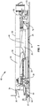
FIG. 1 is a side view of a cart assembly with a table in lowered and horizontal positions. -
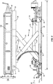
FIG. 2 is a side view of a cart assembly with a table in raised and horizontal positions. -
FIG. 3 is a side view of a cart assembly with a table in raised and vertical positions. -
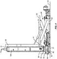
FIG. 4 is a side view of a cart assembly with a table in lowered and vertical positions and a work piece aligned vertically over a trolley. -
FIG. 5 is a side view of a cart assembly with a trolley in an extended position and a work piece supported on the trolley. -
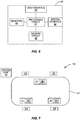
FIG. 6 is a schematic diagram of a control unit for a cart assembly. -
FIG. 7 is a schematic view of an assembly line with cart assemblies movable past work stations. -
FIG. 8 is a flowchart diagram of a method of using a cart assembly with a work piece. - The present disclosure is directed to a cart assembly for positioning a work piece during manufacturing. The cart assembly includes a table with a work surface configured to support the work piece. The table is connected to a base that is movable along a work floor, and a lift mechanism that elevates the table above the work floor. A tilt mechanism provides for adjusting an angle of the table relative to the work floor. The lift and tilt mechanisms may be used separately or simultaneously to adjust the positioning of the table as needed. The cart assembly also includes a trolley. The trolley is configured to receive and support the work piece away from the base. This provides for a worker to access additional sections of the work piece during assembly.
-
Figure 1 illustrates acart assembly 10 that is positioned on awork floor 110. Thecart assembly 10 includes abase 20 and a table 30. Lift and tiltmechanisms work floor 110. Atrolley 60 is connected to thebase 20 and movable relative to thebase 20 along thework floor 110. A work piece (not illustrated) may be moved from the table to thetrolley 60. Thetrolley 60 may then be moved away from the base 20 to position thework piece 100 at additional positions to provide further accessibility for a worker. - The base 20 forms the foundation of the
cart assembly 10. As illustrated inFigures 1 and2 , thebase 20 includes an elongated length L with atop side 23 and abottom side 24.Wheels 22 extend from thebottom side 24 to contact thework floor 110 and provide for movement of thecart assembly 10 along thework floor 110. Thewheels 22 are configured to provide for movement in various directions about the work floor. The base 20 may also include amotor 29 and drivetrain that deliver power to one or more of thewheels 22 for propelling thecart assembly 10 around thework floor 110. In one design, themotor 29 is an electric motor, with other designs including other sources of power. In another design, thecart assembly 10 does not include a motor and drivetrain and relies upon the one or more workers for movement along thework floor 110. - The table 30 is positioned at the
top side 23 of thebase 20. The table 30 includes an elongated shape that extends between afirst end 31 and asecond end 32. Atop side 33 of the table includes awork surface 34 configured to support awork piece 100. Thework surface 34 may extend outward beyond one or bothsides sides work surface 34 is substantially flat such that thework piece 100 can be supported across the length. Thework surface 34 may also include indents, extensions, etc. to conform to the shape of thework piece 100 that is to be supported. Thework surface 34 may also include a textured surface, padding, or other like elements to prevent thework piece 100 from sliding off. Ashelf 38 is connected to the table 30 and extends outward beyond thework surface 34. One design includes theshelf 38 being L-shaped with first and second legs. The first leg is connected to thework surface 34, and the second leg extends outward above thework surface 34. Theshelf 38 may be positioned outward beyond theend 31, or may be positioned at a point along thework surface 34. Theshelf 38 supports thework piece 100 when the table 30 is pivoted by thetilt mechanism 50. - The table 30 may also equipped to secure the
work piece 100 to thework surface 34. One design features one or more straps that are connected to the table 30 and are sized to extend outward over thework piece 100. The table 30 may also include one or more receptacles configured to receive an end of a strap to attach thework piece 100 to the table 30. The receptacles may include openings or indents sized and configured to receive a hook at one or both ends of the straps. The table 30 may also include one or more openings through which a strap can be inserted. One design includes the straps having hook-and-loop members that engage together to secure thework piece 100. Other designs feature buckles, loops, or other elements that provide for securing the straps. - A
lift mechanism 40 is configured to adjust the vertical position of the table 30 relative to thebase 20. The vertical elevation is in the direction indicated by arrow Y and provides for lifting the table 30 away from thework floor 110. In some designs, thelift mechanism 40 is configured to move the table 30 directly away from and towards the base 20 in a direction that is perpendicular to thework floor 110. Other designs move the table 30 relative to the base 20 at a variety of different angles that are not perpendicular to thework floor 110. - One design includes the
lift mechanism 40 being a scissor-lift with first andsecond supports support base 20 and a second end that is connected to the table 30. The supports 41, 42 are positioned in a criss-cross X-pattern arrangement. As illustrated inFigure 2 , this includes the first end of thefirst support 41 and second end of thesecond support 42 on a first side of the intersection, and the second end of thefirst support 41 and the first end of thesecond support 42 being on a second side of the intersection. Thelift mechanism 40 includes a power source that may be powered in various manners including electrical, hydraulic, and pneumatic. One or more of the designs may include a mechanical lift structure with a leadscrew or rack and pinion system that are powered by the power source. One design features a handle that can be cranked by the worked to provide the force for powering thelift mechanism 40 and moving the table 30 between the various elevational positions. - The first and
second supports arms Figure 2 . Other designs may include the two or more layers ofarms -
Figure 1 includes a single set ofsupports base 20. Other designs may feature two or more sets ofsupports supports Figure 2 ). -
Figure 1 illustrates thecart assembly 10 in a lowered position with the table 30 a first distance from thework floor 110. In the lowered position, the table 30 may be located above thebase 20, or may overlap with thebase 20.Figure 2 illustrates a raised positioned with the table 30 elevated above thework floor 110 and away from thebase 20. Thecart assembly 10 may also be positioned at various elevations between the raised and lowered positions as necessary for thework piece 110 to be accessible to the worker. - The
arms work surface 34 parallel to thework floor 110. Thearms work floor 110. - A
tilt mechanism 50 is configured to pivot the table. As illustrated inFigure 3 , the table 30 includes afirst section 35 and asecond section 36. Thefirst section 35 is attached to thelift mechanism 40 and thesecond section 36 includes thework surface 34 that supports thework piece 100. The first andsecond sections pivot 37 that is positioned towards the first end of the table 30 and provides for pivoting movement. In one design, thepivot 37 includes one or more pins that extend through each of the first andsecond sections sections - The
tilt mechanism 50 includes one ormore cylinders 51 that are connected to the underside of thesecond section 36 and to one or more of thefirst section 35 and/orlift mechanism 40. The one ormore cylinders 51 are extendable in length and may be hydraulic, electrical, or pneumatic powered. Thecylinders 51 are movable between a first orientation to position the table 30 at a level orientation as illustrated inFigures 1 and2 and a second orientation to pivot thesecond section 36 relative to thefirst section 35 as illustrated inFigure 3 . In one design, thetilt mechanism 50 provides for selectively pivoting the table within a range between 0° - 90°. The one ormore cylinders 51 are configured to support the table 30 at the various angular positions within the range. - The
tilt mechanism 50 and thelift mechanism 40 are configured to simultaneously position the table 30 at the various angular and elevational positions. Thus, a worker is able to lift and angle the table 30 as needed to position thework piece 100 in a desired orientation. By way of example,Figure 2 illustrates the table 30 in raised and horizontal positions. Thelift mechanism 40 and thetilt mechanism 50 may also be used individually, thus allowing a worker to independently adjust height and angle as necessary. - One or more of the lift and
tilt mechanisms - In one design, the table 30 is parallel to the base 20 when in the horizontal position and perpendicular to the base 20 in the vertical position. In one design, the table 30 is parallel to the
work floor 110 when in the horizontal position and perpendicular to thework floor 110 in the vertical position. - A
trolley 60 is movably attached to thebase 20 and configured to support thework piece 100 away from thebase 20. As illustrated inFigures 4 and5 , thetrolley 60 includes a base 61 withwheels 62 that extend outward to contact against thework floor 110. The base 61 may include various lengths and widths to provide a support structure to support thework piece 110. Thewheels 62 may be positioned about the bottom of the base 61 to support thebase 61 and provide for movement of thetrolley 60 along thework floor 110. In one design, thetrolley 60 is not powered, but rather is movable when pushed and pulled by a worker. Other designs include an engine and drivetrain with one or more of thewheels 62 being powered. - The
trolley 60 is attached to thebase 20 by one ormore arms 63. The one ormore arms 63 provide for thetrolley 60 to move along thework floor 110 between a retracted position as illustrated inFigure 4 in closer proximity to thebase 20 and an extended position as illustrated inFigure 5 . One or more of thearms 63 may include first andsecond sections Figure 5 . Thefirst section 63a includes a straight shape and is sized to slide into a slot that extends along thesecond section 63b. In the retracted position, thesections sections sections trolley 60 and thebase 20. - The one or
more arms 63 may also be disconnected such that thetrolley 60 can moved about thework floor 110 independently from thebase 20. This may include when thework piece 110 is loaded onto thetrolley 60. Thearms 63 may remain attached to thebase 20, to thetrolley 60, or to each (i.e.,first section 63a remains attached to thetrolley 60 andsecond section 63b remains attached to the base 20). Disconnecting thearms 63 may include sliding thefirst arm sections 63a out of the ends of thesecond arm sections 63b. This may also include removing a mechanical fastener at one or both of thetrolley 60 andbase 20 that attaches the one ormore arms 63. Thetrolley 60 can also be reattached to thebase 20 by sliding thearm sections - The
trolley 60 may be secured in the retracted position. One design includes a magnetic release in which thetrolley 60 andbase 20 include magnets that can be magnetically connected together to stow thetrolley 60 in the retracted position. A worker may apply a force to thetrolley 60 to overcome the magnetic force and move thetrolley 60 to the extended position. A mechanical latch may also be provided on one or both of thetrolley 60 andbase 20 to secure thetrolley 60 in the retracted position. - A
carousel 64 is positioned on the top of thebase 61. In one design, thecarousel 64 is rotatable relative to thebase 61, with other designs including thebase 61 and table 64 being fixedly connected. One ormore pins 65 extend upward from the table 64 to engage with thework piece 100 when thework piece 100 is positioned on thetrolley 60. Thepins 65 may include a variety of sizes and shapes, with designs including a length of 10 inches and a circular sectional shape. - As illustrated in
Figure 2 , thepin 65 is located laterally outward from thepivot 37 on the table 30. This provides for thework piece 100 to be aligned vertically above the carousel when the table 30 is tilted to the vertical position (as illustrated inFigure 3 ). Other designs include thetrolley 60 recessed laterally inward of thepivot 37. The user adjusts the lateral position of thetrolley 60 relative to the base 20 when aligning thework piece 100 prior to transfer to thetrolley 60. - As further illustrated in
Figures 3 and4 , thetrolley 60 is vertically overlapped by the first end of the table 30. This positioning provides for thetrolley 60 to receive and support thework piece 100 from the table 30. Once received, thetrolley 60 is horizontally movable along thework floor 110 and is spaced away from thefirst end 31 of the table 30. - An
adapter plate 70 may be attached to thework piece 100 to engage with thetrolley 60 when thework piece 100 is transferred to thetrolley 60. As illustrated inFigures 3 , theadapter plate 70 includes aplate 71 with one ormore extensions 72 extending outward from a first side and anextension 73 extending from an opposing second side. Thefirst extensions 72 are configured to conform to and engage with thework piece 100. Theextensions 72 may include various shapes and sizes to provide for engagement with thework piece 100.Extension 73 may be hollow to form areceptacle 73 sized to receive thepin 65. - The
trolley 60 is configured to support thework piece 100 away from thebase 20. As illustrated inFigure 4 , thework piece 100 is lowered onto thetrolley 60 while in a vertical position on the table 30. With the table 30 in this vertical position, theextension 73 of theadapter plate 70 aligns with thepin 65 of thecarousel 64. Thelift mechanism 40 can lower the table 30 causing thework piece 100 to move downward onto thetrolley 60. Theextension 73 is positioned on thepin 65 and brought into contact with thecarousel 64. - Once the
work piece 100 is on thetrolley 60, thetrolley 60 may be moved away from thebase 20. This includes extending the one ormore arms 63 and sliding thetrolley 60 along thework floor 110. With thetrolley 60 positioned away from thebase 20, thework piece 100 may be rotated on thecarousel 64. This may include rotating theextension 73 of the adapter plate around thepin 65. This rotation provides for additional access to thework piece 100 by the worker. Once completed, thetrolley 60 may be moved back to the retracted position at thebase 20. This includes sliding the one ormore arms 63 together. The table 30 is positioned relative to thework piece 100 with theshelf 38 extending underneath the lower end of thework piece 100. Thelift mechanism 40 may then elevate the table 30 and lift the work piece off thetrolley 60. The lift andtilt mechanisms work piece 100 as necessary. - The
cart assembly 10 includes acontrol unit 80 that controls the operation. Thecontrol unit 80 may signal control steps to thelift mechanism 40,tilt mechanism 50, andmotor 29. Thecontrol unit 80 is typically housed in thebase 20, although it may be located in other components including but not limited to the table 30 and thetrolley 60. - As illustrated in
Figure 6 , thecontrol unit 80 includes one or more processing circuits (shown as processing circuit 81) that may include one or more microprocessors, Application Specific Integrated Circuits (ASICs), or the like, configured with appropriate software and/or firmware. A computer readable storage medium (shown as memory circuit 82) stores data and computer readable program code that configures theprocessing circuit 81 to implement the techniques described above.Memory circuit 82 is a non-transitory computer readable medium, and may include various memory devices such as random access memory, read-only memory, and flash memory. - A worker interface 83 includes one or more user input devices such as a keypad, touchpad, function keys, scroll wheel, or other type of computer input device. The interface 83 may include a display screen, such as a conventional liquid crystal display (LCD) or touch screen display which also functions as a user input device. The interface 83 provides for the worker to control the functions of the various components that are in communication with the
control unit 80. - A
system interface 84 is configured to communications with a remote source. In one design, this includes asystem controller 90. This may also include a remote control source used by the worker who is remote from thecart assembly 10. Thesystem interface 84 includes a transceiver configured to wirelessly communicate with the remote source. Thesystem interface 84 may also provide for hardwire connection with the remote source. Thesystem interface 84 may also provide for the supply of power from a remote source. - The
control unit 80 may also include a power source 86. The power source 86 may be used in the event of failure of receiving power from the remote source. The power source 86 may also provide power to just one or more limited elements, such as theprocessing circuit 81 and thememory circuit 82. The power source may be rechargeable battery pack that includes a set of battery cells configured to power electrical equipment. - One or
more sensors 85 may detect the presence of an object within a work envelope of the cart assembly. This may include within a specific distance of thebase 20, such as a ten foot area. Thesensors 85 detect a person or object within a predetermined distance of thecart assembly 10 and signals to stop operation of one or more components to prevent a potentially unsafe condition. Thesensors 85 are configured to detect the object. Various sensor types may be used, including a camera, heat sensor, and movement sensor. - In some designs, the
cart assembly 10 is a stand-alone device that operates independently. Other designs include thecart assembly 10 being a component within a larger work area system such as anassembly line 120 as illustrated inFigure 7 . Theassembly line 120 includes one ormore cart assemblies 10 that move around anassembly track 121.Work stations 125 are positioned around thetrack 121 and each is configured to perform one or more assembly steps on thework pieces 100. - Some or all functionality of the
cart assemblies 10 may be controlled by asystem controller 90. Thesystem controller 90 communicates with thecart assemblies 10 and controls and oversees the operation of theassembly line 120. Thesystem controller 90 may be housed in a cabinet or the like at some distance from theassembly line 120. Thesystem controller 90 may include a control circuit with one or more microprocessors, microcontrollers, and ASICs that with appropriate software and/or firmware. A memory circuit stores data and computer readable program code that configures the control circuit to implement the techniques described above. Memory circuit is a non-transitory computer readable medium, and may include various memory devices such as random access memory, read-only memory, and flash memory. Thesystem controller 90 may also include an interface to send and receive data to thecart assemblies 10. - Communications between the
system controller 90 andcart assemblies 10 may occur through a cabling system with various cables extending between the elements. The cables are configured for carrying various data signals. In one design, the system communicates through a LAN, with another design featuring communication through a communications bus. The communication may also include a wireless interface, such as through a Bluetooth interface or wireless local area network (WLAN) interface. Some embodiments feature a combination of cabling and wireless communications. The cabling system may further be configured to provide power from a power source to thecart assemblies 10. Control information from eachcart assembly 10, such as angle, elevational information, and drive train information, is signaled to thesystem controller 90. Thesystem controller 90 is then able to monitor the assembly process and transmit control signals to thecart assemblies 10 as necessary to continue the process. -
Figure 8 illustrates one method of using thecart assembly 10 with awork piece 100. Initially, thework piece 100 is positioned on thework surface 34 of the table 30 (block 90). The table 30 may be at various heights above thework floor 110 and/or angular orientations relative to thework floor 110 when thework piece 100 is positioned on thework surface 34. This may include the table 30 being in a lowered positioned with thework surface 34 parallel to the work floor. After positioning on the table 30, thework piece 100 is secured onto thework surface 34. This may include positioning one or more straps over thework piece 100 and securing the straps to the table 30. - The table 30 is then elevated and angled at the desired orientation (blocks 91, 92). The
lift mechanism 40 is activated to adjust the elevation and thetilt mechanism 50 is activated to adjust the angle. The elevation and angular movements may be performed sequentially, or may be performed simultaneously. Adjustments of the height and/or angle provide for the worker to access the various sections of thework piece 100 to perform the various assembly steps. - The
work piece 100 may also be moved to thetrolley 60 for additional assembly steps (block 93). Prior to moving thework piece 100 to thetrolley 60, anassembly plate 70 may be attached to thework piece 100. This may include positioning one or more of theextensions 72 into receptacles in thework piece 100. Fasteners may be secured to theextensions 72 to secure theadapter plate 70 to thework piece 100. In another design, anadapter plate 70 is not used, but rather thework piece 100 is configured to engage with thetrolley 60. - To move the
work piece 100 to thetrolley 60, the table 30 is positioned to be vertically above thetrolley 60. In one design, this includes positioning the table 30 at a vertical position (i.e., perpendicular relative to the work floor 110). This positions a section of thework piece 100 directly over thetrolley 60. This orientation of the table 30 may result in thework piece 110 being supported by theshelf 38 that extends outward from thework surface 34. Thetrolley 60 may be positioned in a retracted position to receive thework piece 100. In another design, thetrolley 60 is in an extended position outward from thebase 20. - Once the
work piece 100 is aligned with thetrolley 60, the table 30 is lowered such that thework piece 100 is moved onto and supported on thecarousel 64. When anadapter plate 70 is used, this includes inserting thepin 65 on thetrolley 60 into an opening in theadapter plate 70. Straps, fasteners, or other like mechanical connectors may further secure thework piece 100 to thetrolley 60. Without an adapter plate, thework piece 100 may be simply positioned on the surface of thecarousel 64 and secured by straps, fasteners, or some other mechanical connectors. - Once the
work piece 100 is on thetrolley 60, thetrolley 60 may be moved away from the base 20 (block 94). This may include extending thetrolley 60 outward from thebase 20 along thearms 63. This may also include detaching thetrolley 60 from thebase 20. In the various designs, different portions of thework piece 100 are accessible for the user to perform additional assembly steps. For example, the side of thework piece 100 that was facing the table 30 is now accessible for the user. Further, thework piece 100 may be rotated on thetrolley 60 to provide access as necessary. This includes theadapter plate 70 rotating around thepin 65 as the user applies a rotating force to thework piece 100. This may also include thecarousel 64 rotating relative to thebase 61 of thetrolley 60. - The
trolley 60 and thework piece 100 may remain detached from the base 20 as the remainder of thecart assembly 10 moves along theassembly line 120. Alternatively, thetrolley 60 may be reattached to thebase 20 and thecart assembly 10 andwork piece 100 are moved along theassembly line 120. - When the
trolley 60 is reattached, the table 30 may be positioned to re-engage with thework piece 100. This may include positioning the table 30 in the lowered and vertical positions, and laterally moving theshelf 38 on thework surface 34 underneath the lower edge of thework piece 100. The table 30 may then be raised with thework piece 100 being lifted off of thetrolley 60 and onto the table 30. Thework piece 100 may be angled as needed during or after the lifting process. - The variations and alternatives of the present disclosure relate to the manufacture and use of components and parts such as, for example, composite component parts of any dimension, including the manufacture and use of components and parts in the fabrication of larger parts and structures. Such devices include, but are not limited to, components and parts designed to be positioned on the exterior or interior of stationary objects including, without limitation, bridge trusses, support columns and structures, general construction objects, etc. Further structures and objects include vehicles, such as, without limitation, aircraft, satellites, rockets, missiles, etc., and therefore further include manned and unmanned aircraft, manned and unmanned spacecraft, manned and unmanned rotorcraft, manned and unmanned terrestrial vehicles, manned and unmanned non-terrestrial vehicles, manned and unmanned surface and sub-surface water-borne vehicles, objects, and structures. Particularly contemplated components include aircraft stringer, spars, ribs, as well as components comprising other planar and non-planar geometries used in the manufacture of aircraft components and parts, etc.
- While the preferred variations and alternatives of the present disclosure have been illustrated and described, it will be appreciated that various changes and substitutions can be made therein without departing from the spirit and scope of the disclosure. Accordingly, the scope of the disclosure should only be limited by the accompanying claims and equivalents thereof. When introducing elements of the present disclosure or exemplary aspects or embodiment(s) thereof, the articles "a," "an," "the" and "said" are intended to mean that there are one or more of the elements. The terms "comprising," "including" and "having" are intended to be inclusive and mean that there may be additional elements other than the listed elements. Although this disclosure has been described with respect to specific embodiments, the details of these embodiments are not to be construed as limitations. While the preferred variations and alternatives of the present disclosure have been illustrated and described, it will be appreciated that various changes and substitutions can be made therein without departing from the spirit and scope of the disclosure.
- Further, the disclosure comprises embodiments according to the following clauses:
- Clause 1. A cart assembly configured to move a work piece about a work floor, the cart assembly comprising:
- a base having a top side and a bottom side spaced from the top side, the bottom side configured to be supported on the work floor;
- a table positioned on the top side of the base and comprising a first end, a second end spaced from the first end, a pivot disposed towards the first end, and a work surface that extends between the first and second ends and configured to support the work piece, the table pivotally mounted to move about the pivot between a horizontal position and a vertical position;
- a tilt mechanism coupled to the table and configured to rotate the table about the pivot between the horizontal position and the vertical position;
- a lift mechanism disposed between the base and the table, the lift mechanism configured to move the table relative to the base between a lowered position defining a first distance above the work floor and a raised position defining a second distance above the work floor that is greater than the first distance; and
- a trolley comprising wheels configured to be supported on the work floor, the trolley connected to the base and horizontally movable relative to the base along the work floor between a retracted position and an extended position;
- wherein in the retracted position, the trolley is vertically overlapped by the first end of the table and in the extended position the trolley is horizontally spaced away from the first end of the table.
- Clause 2. The cart assembly of Clause 1, further comprising at least one slide that connects the trolley to the base, the at least one slide configured to prevent the trolley from rotating relative to the base.
- Clause 3. The cart assembly of Clause 2, wherein the trolley is detachable from the at least one slide to remove the trolley from the base.
- Clause 4. The cart assembly of Clause 1, wherein the trolley further comprises a carousel operatively connected to the wheels and configured to rotate relative to the wheels.
- Clause 5. The cart assembly of Clause 4, wherein the trolley further comprises a pin that extends outward from the carousel, the pin sized to engage with the work piece.
- Clause 6. The cart assembly of Clause 1, wherein the table is parallel to the base when in the horizontal position and perpendicular to the base when in the vertical position.
- Clause 7. The cart assembly of Clause 1, further comprising:
- a processing circuit communicatively connected to the lift mechanism and the tilt mechanism;
- a drive train to drive the base along the work floor; and
- a wireless transceiver operatively connected to the processing circuit and configured to wirelessly communicate with a remote source to remotely control the drive train, the tilt mechanism, and the lift mechanism.
- Clause 8. The cart assembly of Clause 7, further comprising a sensing circuit operatively connected to the processing circuit, the sensing circuit configured to detect an object within a physical envelope around the cart assembly and to signal the processing circuit to prevent movement of the cart assembly when the object is detected.
- Clause 9. A cart assembly configured to move a work piece about a work floor, the cart assembly comprising:
- a base with a top side and a bottom side spaced from the top side, the bottom side configured to be supported on the work floor;
- a table positioned on the top side of the base, the table having a pivot and presenting a work surface configured to support the work piece;
- a lift mechanism disposed between the base and the table, the lift mechanism configured to move the table relative to the base between a lowered position and a raised position;
- a tilt mechanism connected to the table and configured to rotate the table about the pivot between a horizontal position and a vertical position; and
- a trolley configured to be supported on the work floor, the trolley connected to the base and horizontally movable along the work floor relative to the base between a retracted position and an extended position;
- the cart assembly being movable between first, second, third, fourth, and fifth positions;
- in the first position the table is in the lowered and horizontal positions and the trolley is in the retracted position;
- in the second position the table is in the raised and horizontal positions and the trolley is in the retracted position;
- in the third position the table is in the raised and vertical positions and the trolley is in the retracted position;
- in the fourth position the table is in the lowered and vertical positions and the trolley is in the retracted position;
- in the fifth position the table is in the vertical position and the trolley is in the extended position.
-
Clause 10. The cart assembly of Clause 9, wherein the lift mechanism comprises a scissor lift comprising first and second arms with each of the arms having a first end connected to the base and a second end connected to the table. - Clause 11. The cart assembly of Clause 9, further comprising an adapter plate configured to be attached to the work piece to secure the work piece to the trolley.
- Clause 12. The cart assembly of Clause 9, further comprising at least one slide that connects the trolley to the base, the at least one slide configured to prevent the trolley from rotating relative to the base and to locate the trolley between the extended and retracted positions.
- Clause 13. The cart assembly of Clause 12, wherein the trolley comprises wheels to move along the work floor, the trolley also comprises a carousel mounted to the wheels and that rotates relative to the wheels.
- Clause 14. The cart assembly of Clause 9, further comprising:
- a processing circuit communicatively connected to the lift mechanism and the tilt mechanism;
- a drive train to drive the base along the work floor; and
- a wireless transceiver operatively connected to the processing circuit and configured to wirelessly communicate with a remote source to remotely control the lift mechanism and the tilt mechanism to move the cart assembly between the first, second, third, fourth, and fifth positions.
- Clause 15. A method of using a cart assembly to move a work piece about a work floor, the method comprising:
- supporting the work piece with a table, the table being attached to a base that is positioned on the work floor;
- positioning the table and the work piece in a lowered position a first distance from the work floor and with the table and the work piece in a horizontal position;
- raising the table away from the work floor to a raised position while the work piece is supported on the table and the base is on the work floor and the work piece is in the horizontal position;
- rotating the table and positioning the work piece transverse to the work floor while the work piece is supported on the table and the base is on the work floor and the table is in the raised position;
- positioning the work piece vertically over a trolley that is on the work floor and that is attached to base;
- lowering the table towards the work floor and positioning the work piece onto the trolley while the trolley is on the floor and is attached to the base while the work piece is supported on the table and the base is on the work floor;
- supporting the work piece on the trolley and removing the work piece from the table; and
- moving the trolley along the work floor away from the base while the trolley is supporting the work piece.
- Clause 16. The method of Clause 15, further comprising supporting the work piece on a shelf of an elbow member that is attached to and that extends outward from the table while the table is in the vertical position.
- Clause 17. The method of Clause 15, further comprising simultaneously moving the base along the work floor while rotating and raising the table.
- Clause 18. The method of Clause 15, further comprising remotely rotating and raising the table.
- Clause 19. The method of Clause 15, further comprising rotating the table 90° between the horizontal position and a vertical position.
-
Clause 20. The method of Clause 15, further comprising detaching the trolley from the base while the trolley is supporting the work piece. - The present invention may, of course, be carried out in other ways than those specifically set forth herein without departing from essential characteristics of the invention. The present embodiments are to be considered in all respects as illustrative and not restrictive, and all changes coming within the meaning and equivalency range of the appended claims are intended to be embraced therein.
Claims (14)
- A cart assembly configured to move a work piece about a work floor, the cart assembly comprising:a base (20) having a top side (23) and a bottom side (24) spaced from the top side (23), the bottom side (24) configured to be supported on the work floor;a table (30) positioned on the top side (23) of the base (20) and comprising a first end (31), a second end (32) spaced from the first end (31), a pivot (37) disposed towards the first end (31), and a work surface (34) that extends between the first and second ends (31, 32) and configured to support the work piece, the table (30) pivotally mounted to move about the pivot (37) between a horizontal position and a vertical position;a tilt mechanism (50) coupled to the table (30) and configured to rotate the table (30) about the pivot (37) between the horizontal position and the vertical position;a lift mechanism (40) disposed between the base (20) and the table (30), the lift mechanism (40) configured to move the table (30) relative to the base (20) between a lowered position defining a first distance above the work floor and a raised position defining a second distance above the work floor that is greater than the first distance; anda trolley (60) comprising wheels (62) configured to be supported on the work floor, the trolley (60) connected to the base (20) and horizontally movable relative to the base (20) along the work floor between a retracted position and an extended position;wherein in the retracted position, the trolley (60) is vertically overlapped by the first end (31) of the table (30) and in the extended position the trolley (60) is horizontally spaced away from the first end (31) of the table (30).
- The cart assembly of claim 1, further comprising at least one slide (63) that connects the trolley (60) to the base (20), the at least one slide (63) configured to prevent the trolley (60) from rotating relative to the base (20).
- The cart assembly of claim 2, wherein the trolley (60) is detachable from the at least one slide (63) to remove the trolley (60) from the base (20).
- The cart assembly of any one of claims 1-3, wherein the trolley (60) further comprises a carousel (64) operatively connected to the wheels (62) and configured to rotate relative to the wheels (62).
- The cart assembly of claim 4, wherein the trolley (60) further comprises a pin (65) that extends outward from the carousel (64), the pin (65) sized to engage with the work piece.
- The cart assembly of any one of claims 1-5, wherein the table (30) is parallel to the base (20) when in the horizontal position and perpendicular to the base (20) when in the vertical position.
- The cart assembly of any one of claims 1-6, further comprising:a processing circuit (81) communicatively connected to the lift mechanism (40) and the tilt mechanism (50);a drive train (29) to drive the base (20) along the work floor; anda wireless transceiver (84) operatively connected to the processing circuit (81) and configured to wirelessly communicate with a remote source to remotely control the drive train (29), the tilt mechanism (50), and the lift mechanism (40).
- The cart assembly of claim 7, further comprising a sensing circuit (85) operatively connected to the processing circuit (81), the sensing circuit (85) configured to detect an object within a physical envelope around the cart assembly (10) and to signal the processing circuit (81) to prevent movement of the cart assembly (10) when the object is detected.
- A method of using a cart assembly to move a work piece about a work floor, the method comprising:supporting the work piece with a table (30), the table (30) being attached to a base (20) that is positioned on the work floor;positioning the table (30) and the work piece in a lowered position a first distance from the work floor and with the table (30) and the work piece in a horizontal position;raising the table (30) away from the work floor to a raised position while the work piece is supported on the table (30) and the base (20) is on the work floor and the work piece is in the horizontal position;rotating the table (30) and positioning the work piece transverse to the work floor while the work piece is supported on the table (30) and the base (20) is on the work floor and the table (30) is in the raised position;positioning the work piece vertically over a trolley (60) that is on the work floor and that is attached to base (20);lowering the table (30) towards the work floor and positioning the work piece onto the trolley (60) while the trolley (60) is on the floor and is attached to the base (20) while the work piece is supported on the table (30) and the base (20) is on the work floor;supporting the work piece on the trolley (60) and removing the work piece from the table (30); andmoving the trolley (30) along the work floor away from the base (20) while the trolley (60) is supporting the work piece.
- The method of claim 9, further comprising supporting the work piece on a shelf (38) of an elbow member that is attached to and that extends outward from the table (30) while the table (30) is in the vertical position.
- The method of claims 9 or 10, further comprising simultaneously moving the base (20) along the work floor while rotating and raising the table (30).
- The method of any one of claims 9-11, further comprising remotely rotating and raising the table (30).
- The method of any one of claims 9-12, further comprising rotating the table (30) 90° between the horizontal position and a vertical position.
- The method of any one of claims 9-13, further comprising detaching the trolley (60) from the base (20) while the trolley (60) is supporting the work piece.
Applications Claiming Priority (1)
| Application Number | Priority Date | Filing Date | Title |
|---|---|---|---|
| US15/671,825 US10457184B2 (en) | 2017-08-08 | 2017-08-08 | Cart assembly for use with a work piece and methods of use |
Publications (2)
| Publication Number | Publication Date |
|---|---|
| EP3441351A1 true EP3441351A1 (en) | 2019-02-13 |
| EP3441351B1 EP3441351B1 (en) | 2020-09-02 |
Family
ID=63014318
Family Applications (1)
| Application Number | Title | Priority Date | Filing Date |
|---|---|---|---|
| EP18183816.0A Active EP3441351B1 (en) | 2017-08-08 | 2018-07-16 | Cart assembly for use with a work piece and methods of use |
Country Status (6)
| Country | Link |
|---|---|
| US (1) | US10457184B2 (en) |
| EP (1) | EP3441351B1 (en) |
| JP (1) | JP7138507B2 (en) |
| CN (1) | CN109382650B (en) |
| CA (1) | CA3009774C (en) |
| MX (1) | MX2018009647A (en) |
Families Citing this family (27)
| Publication number | Priority date | Publication date | Assignee | Title |
|---|---|---|---|---|
| US10336596B2 (en) * | 2017-10-20 | 2019-07-02 | Oshkosh Corporation | Scissor deck access arrangement |
| WO2019092682A1 (en) * | 2017-11-13 | 2019-05-16 | Nhon Hoa Nguyen | Lifting cart for building construction |
| US11530623B2 (en) * | 2019-04-11 | 2022-12-20 | The Boeing Company | Systems and methods for positioning aircraft engine components |
| CN110065650B (en) * | 2019-05-24 | 2024-03-12 | 凌云(宜昌)航空装备工程有限公司 | Work platform for repairing aircraft nose of electric lifting aircraft |
| CN110293530A (en) * | 2019-06-25 | 2019-10-01 | 顺德职业技术学院 | The mounting platform of bottom plate of electric cabinet |
| CN112238431A (en) * | 2019-07-16 | 2021-01-19 | 廊坊市万丽装饰工程有限公司 | Rotary tilting worktable for door and window production |
| CN110316677A (en) * | 2019-07-19 | 2019-10-11 | 江苏中联风能机械股份有限公司 | Large-size machine assembles handling device and assembly method for carrying |
| US11865960B2 (en) * | 2019-10-09 | 2024-01-09 | New Heights, Llc | Material delivery and waste removal trailer |
| CN111591919B (en) * | 2020-05-29 | 2025-01-07 | 力成运维(宁夏)电力技术有限公司 | A height and width adjustable circuit breaker transfer trolley |
| CN113829290B (en) * | 2020-06-23 | 2023-02-24 | 中冶宝钢技术服务有限公司 | Sector block disassembly tool and disassembly inspection method thereof |
| CN111702704A (en) * | 2020-07-17 | 2020-09-25 | 龙杰机械装备(太仓)有限公司 | Special machine for disassembly and assembly of inner manhole cover |
| DE102020121883A1 (en) * | 2020-08-20 | 2022-02-24 | Fraunhofer-Gesellschaft zur Förderung der angewandten Forschung eingetragener Verein | Vehicle with cargo pick-up |
| CN114313287A (en) * | 2020-09-25 | 2022-04-12 | 北京二郎神科技有限公司 | Unmanned aerial vehicle battery positioning device, battery control system and positioning and control method thereof |
| CN112225118A (en) * | 2020-10-13 | 2021-01-15 | 苏州美罗升降机械有限公司 | Electric push-pull device |
| CN112357821B (en) * | 2020-11-02 | 2024-01-02 | 新疆国统管道股份有限公司 | PCCP spiral welding and water pressure inspection automatic assembly line and application method thereof |
| CN112247421A (en) * | 2020-11-02 | 2021-01-22 | 新疆国统管道股份有限公司 | PCCP spiral welding steel cylinder automatic delivery and turnover integrated machine and application thereof |
| CN112573454A (en) * | 2020-11-25 | 2021-03-30 | 浙江精功精密制造有限公司 | A large cylinder erecting device |
| CN112621681B (en) * | 2020-12-28 | 2025-04-08 | 江西泰豪智能电力科技有限公司 | Object placing platform |
| CN112875568B (en) * | 2021-01-11 | 2022-06-21 | 安徽升业工程机械有限公司 | Multi-angle conveying platform of elevator |
| US12013281B2 (en) * | 2021-03-05 | 2024-06-18 | The Boeing Company | Deadweight loading apparatus, system, and method for calibrating a testing device |
| CN113086901B (en) * | 2021-03-29 | 2022-06-10 | 黑龙江工程学院 | Intelligent transportation robot |
| KR102575708B1 (en) * | 2021-08-10 | 2023-09-07 | 제일에스컬레이터(주) | Control box lifting device for escalator |
| CN114714076B (en) * | 2022-03-18 | 2022-11-22 | 佛山市南海建泰铝制品有限公司 | Annular assembly line of walking aid appliance |
| US12434374B2 (en) | 2022-10-20 | 2025-10-07 | Toyota Motor Engineering & Manufacturing North America, Inc. | Work part delivery system and apparatus |
| CN115503974A (en) * | 2022-10-31 | 2022-12-23 | 芜湖创联航空装备产业研究院有限公司 | A Modular Workstation for Ground Station Synthesis, Debugging and Trial |
| CN117260636A (en) * | 2023-10-11 | 2023-12-22 | 东风本田发动机有限公司 | How to disassemble the trolley device and gearbox |
| CN117922835B (en) * | 2024-03-22 | 2024-06-18 | 成都航空职业技术学院 | A loading device and a control method thereof |
Citations (5)
| Publication number | Priority date | Publication date | Assignee | Title |
|---|---|---|---|---|
| FR2685911A1 (en) * | 1992-01-03 | 1993-07-09 | Bretagne Concept Sarl | Device for manipulating bulky and heavy articles in the form of rolls |
| WO1995029865A1 (en) * | 1994-04-29 | 1995-11-09 | Roll Systems, Inc. | Method and apparatus for business forms processing |
| WO2006133700A1 (en) * | 2005-06-17 | 2006-12-21 | Mogens Lyngby Pedersen | Procedure for the transportation of tires or car wheels, which are demounted from a car, to another place in a garage to be processed, and back again, and a frame for the carrying out of the procedure |
| US20140027693A1 (en) * | 2012-07-26 | 2014-01-30 | Mopec, Inc. | Scissor lift apparatus |
| US20170050830A1 (en) * | 2015-08-21 | 2017-02-23 | The Boeing Company | Component moving system and method |
Family Cites Families (11)
| Publication number | Priority date | Publication date | Assignee | Title |
|---|---|---|---|---|
| US2335692A (en) * | 1943-01-30 | 1943-11-30 | Thomas W Murray | Supporting table and jack |
| US3811579A (en) * | 1972-09-25 | 1974-05-21 | D Black | Mechanized van loading and unloading apparatus and system |
| JPS5823737U (en) * | 1981-08-10 | 1983-02-15 | 金子農機株式会社 | Transloading device for agricultural vehicles |
| JPH1135392A (en) * | 1997-07-15 | 1999-02-09 | Shinetsu Eng Kk | Spindle-shaped silicon product reversing elevating device |
| JP3520466B2 (en) * | 1999-08-06 | 2004-04-19 | 日産車体株式会社 | Locator linear guide device |
| JP2006008300A (en) * | 2004-06-24 | 2006-01-12 | Yamato Trackwork System Co Ltd | Lengthy article processing device |
| US20070126196A1 (en) * | 2005-06-29 | 2007-06-07 | Klahn Kenneth F | Third axle assembly for log hauling trailers |
| WO2010124287A2 (en) * | 2009-04-24 | 2010-10-28 | Michael Leonard | Modular transport apparatus |
| CN201737451U (en) * | 2010-07-15 | 2011-02-09 | 周大同 | Movable lifting overturning dolly |
| US10414318B2 (en) * | 2016-04-28 | 2019-09-17 | Rakkatec Oy | Arrangement for optimizing load position in relation to transportation vehicle |
| CN206068751U (en) * | 2016-08-24 | 2017-04-05 | 深圳市科陆电子科技股份有限公司 | A kind of device for overturning for battery and carrying |
-
2017
- 2017-08-08 US US15/671,825 patent/US10457184B2/en active Active
-
2018
- 2018-06-27 CA CA3009774A patent/CA3009774C/en active Active
- 2018-07-16 EP EP18183816.0A patent/EP3441351B1/en active Active
- 2018-08-03 JP JP2018147111A patent/JP7138507B2/en active Active
- 2018-08-07 CN CN201810888119.5A patent/CN109382650B/en active Active
- 2018-08-08 MX MX2018009647A patent/MX2018009647A/en unknown
Patent Citations (5)
| Publication number | Priority date | Publication date | Assignee | Title |
|---|---|---|---|---|
| FR2685911A1 (en) * | 1992-01-03 | 1993-07-09 | Bretagne Concept Sarl | Device for manipulating bulky and heavy articles in the form of rolls |
| WO1995029865A1 (en) * | 1994-04-29 | 1995-11-09 | Roll Systems, Inc. | Method and apparatus for business forms processing |
| WO2006133700A1 (en) * | 2005-06-17 | 2006-12-21 | Mogens Lyngby Pedersen | Procedure for the transportation of tires or car wheels, which are demounted from a car, to another place in a garage to be processed, and back again, and a frame for the carrying out of the procedure |
| US20140027693A1 (en) * | 2012-07-26 | 2014-01-30 | Mopec, Inc. | Scissor lift apparatus |
| US20170050830A1 (en) * | 2015-08-21 | 2017-02-23 | The Boeing Company | Component moving system and method |
Also Published As
| Publication number | Publication date |
|---|---|
| JP2019052047A (en) | 2019-04-04 |
| CN109382650A (en) | 2019-02-26 |
| CA3009774A1 (en) | 2019-02-08 |
| US10457184B2 (en) | 2019-10-29 |
| US20190047458A1 (en) | 2019-02-14 |
| MX2018009647A (en) | 2019-03-28 |
| EP3441351B1 (en) | 2020-09-02 |
| CN109382650B (en) | 2022-04-05 |
| CA3009774C (en) | 2022-10-18 |
| JP7138507B2 (en) | 2022-09-16 |
Similar Documents
| Publication | Publication Date | Title |
|---|---|---|
| CA3009774C (en) | Cart assembly for use with a work piece and methods of use | |
| CN106829807B (en) | Modular motorized mover attachment | |
| EP3236332B1 (en) | Method and system for transporting inventory items | |
| EP1930289B1 (en) | Center of gravity sensing and adjusting load bar, program product, and related methods | |
| ES2616101T3 (en) | Modular upright system | |
| US8690510B1 (en) | Self-lifting robotic device movable in desired horizontal directions | |
| US20130240812A1 (en) | Electronically controlled wheel lift system | |
| JP6417265B2 (en) | Modular support system | |
| WO2014009797A1 (en) | Robotic device movable in three mutually perpendicular directions | |
| CA3045999C (en) | Work platform mover system | |
| US10173237B2 (en) | Apparatus and method for building a product from a base member and one or more attaching members | |
| EP3523664A1 (en) | Manipulator | |
| CN103261028A (en) | Arrangement for handling of luggage | |
| CN114683017A (en) | Equipment assembling system and method | |
| KR20160063830A (en) | Automatic Transfer Vehicle | |
| CN112319581A (en) | Automatic assembly fixture for antenna array surface | |
| CN110509236B (en) | Working table | |
| WO2021050021A1 (en) | Wheeled military land vehicles assembly/disassembly automation system | |
| CN113548410B (en) | A material transfer conveying trolley | |
| US11001460B2 (en) | Method and tool cart for transferring a tool component | |
| CN115320880A (en) | Automatic attitude-adjusting docking method for outer wing of airplane | |
| CN114952215A (en) | Appearance butt joint platform is transferred in portable outer wing support | |
| CN212531202U (en) | Petroleum asphalt glass fiber tire asphalt felt stacking device | |
| CN208375168U (en) | The disassembling stations of adjustable posture | |
| CN207241757U (en) | A kind of new PM trolleys |
Legal Events
| Date | Code | Title | Description |
|---|---|---|---|
| PUAI | Public reference made under article 153(3) epc to a published international application that has entered the european phase |
Free format text: ORIGINAL CODE: 0009012 |
|
| STAA | Information on the status of an ep patent application or granted ep patent |
Free format text: STATUS: REQUEST FOR EXAMINATION WAS MADE |
|
| 17P | Request for examination filed |
Effective date: 20180716 |
|
| AK | Designated contracting states |
Kind code of ref document: A1 Designated state(s): AL AT BE BG CH CY CZ DE DK EE ES FI FR GB GR HR HU IE IS IT LI LT LU LV MC MK MT NL NO PL PT RO RS SE SI SK SM TR |
|
| AX | Request for extension of the european patent |
Extension state: BA ME |
|
| RBV | Designated contracting states (corrected) |
Designated state(s): AL AT BE BG CH CY CZ DE DK EE ES FI FR GB GR HR HU IE IS IT LI LT LU LV MC MK MT NL NO PL PT RO RS SE SI SK SM TR |
|
| GRAP | Despatch of communication of intention to grant a patent |
Free format text: ORIGINAL CODE: EPIDOSNIGR1 |
|
| STAA | Information on the status of an ep patent application or granted ep patent |
Free format text: STATUS: GRANT OF PATENT IS INTENDED |
|
| INTG | Intention to grant announced |
Effective date: 20200114 |
|
| GRAS | Grant fee paid |
Free format text: ORIGINAL CODE: EPIDOSNIGR3 |
|
| GRAJ | Information related to disapproval of communication of intention to grant by the applicant or resumption of examination proceedings by the epo deleted |
Free format text: ORIGINAL CODE: EPIDOSDIGR1 |
|
| GRAL | Information related to payment of fee for publishing/printing deleted |
Free format text: ORIGINAL CODE: EPIDOSDIGR3 |
|
| STAA | Information on the status of an ep patent application or granted ep patent |
Free format text: STATUS: REQUEST FOR EXAMINATION WAS MADE |
|
| GRAR | Information related to intention to grant a patent recorded |
Free format text: ORIGINAL CODE: EPIDOSNIGR71 |
|
| STAA | Information on the status of an ep patent application or granted ep patent |
Free format text: STATUS: GRANT OF PATENT IS INTENDED |
|
| INTC | Intention to grant announced (deleted) | ||
| INTG | Intention to grant announced |
Effective date: 20200602 |
|
| GRAA | (expected) grant |
Free format text: ORIGINAL CODE: 0009210 |
|
| STAA | Information on the status of an ep patent application or granted ep patent |
Free format text: STATUS: THE PATENT HAS BEEN GRANTED |
|
| AK | Designated contracting states |
Kind code of ref document: B1 Designated state(s): AL AT BE BG CH CY CZ DE DK EE ES FI FR GB GR HR HU IE IS IT LI LT LU LV MC MK MT NL NO PL PT RO RS SE SI SK SM TR |
|
| REG | Reference to a national code |
Ref country code: GB Ref legal event code: FG4D |
|
| REG | Reference to a national code |
Ref country code: AT Ref legal event code: REF Ref document number: 1308602 Country of ref document: AT Kind code of ref document: T Effective date: 20200915 Ref country code: CH Ref legal event code: EP |
|
| REG | Reference to a national code |
Ref country code: DE Ref legal event code: R096 Ref document number: 602018007425 Country of ref document: DE |
|
| REG | Reference to a national code |
Ref country code: IE Ref legal event code: FG4D |
|
| REG | Reference to a national code |
Ref country code: LT Ref legal event code: MG4D |
|
| PG25 | Lapsed in a contracting state [announced via postgrant information from national office to epo] |
Ref country code: FI Free format text: LAPSE BECAUSE OF FAILURE TO SUBMIT A TRANSLATION OF THE DESCRIPTION OR TO PAY THE FEE WITHIN THE PRESCRIBED TIME-LIMIT Effective date: 20200902 Ref country code: LT Free format text: LAPSE BECAUSE OF FAILURE TO SUBMIT A TRANSLATION OF THE DESCRIPTION OR TO PAY THE FEE WITHIN THE PRESCRIBED TIME-LIMIT Effective date: 20200902 Ref country code: HR Free format text: LAPSE BECAUSE OF FAILURE TO SUBMIT A TRANSLATION OF THE DESCRIPTION OR TO PAY THE FEE WITHIN THE PRESCRIBED TIME-LIMIT Effective date: 20200902 Ref country code: NO Free format text: LAPSE BECAUSE OF FAILURE TO SUBMIT A TRANSLATION OF THE DESCRIPTION OR TO PAY THE FEE WITHIN THE PRESCRIBED TIME-LIMIT Effective date: 20201202 Ref country code: GR Free format text: LAPSE BECAUSE OF FAILURE TO SUBMIT A TRANSLATION OF THE DESCRIPTION OR TO PAY THE FEE WITHIN THE PRESCRIBED TIME-LIMIT Effective date: 20201203 Ref country code: SE Free format text: LAPSE BECAUSE OF FAILURE TO SUBMIT A TRANSLATION OF THE DESCRIPTION OR TO PAY THE FEE WITHIN THE PRESCRIBED TIME-LIMIT Effective date: 20200902 Ref country code: BG Free format text: LAPSE BECAUSE OF FAILURE TO SUBMIT A TRANSLATION OF THE DESCRIPTION OR TO PAY THE FEE WITHIN THE PRESCRIBED TIME-LIMIT Effective date: 20201202 |
|
| REG | Reference to a national code |
Ref country code: NL Ref legal event code: MP Effective date: 20200902 |
|
| REG | Reference to a national code |
Ref country code: AT Ref legal event code: MK05 Ref document number: 1308602 Country of ref document: AT Kind code of ref document: T Effective date: 20200902 |
|
| PG25 | Lapsed in a contracting state [announced via postgrant information from national office to epo] |
Ref country code: RS Free format text: LAPSE BECAUSE OF FAILURE TO SUBMIT A TRANSLATION OF THE DESCRIPTION OR TO PAY THE FEE WITHIN THE PRESCRIBED TIME-LIMIT Effective date: 20200902 Ref country code: PL Free format text: LAPSE BECAUSE OF FAILURE TO SUBMIT A TRANSLATION OF THE DESCRIPTION OR TO PAY THE FEE WITHIN THE PRESCRIBED TIME-LIMIT Effective date: 20200902 Ref country code: LV Free format text: LAPSE BECAUSE OF FAILURE TO SUBMIT A TRANSLATION OF THE DESCRIPTION OR TO PAY THE FEE WITHIN THE PRESCRIBED TIME-LIMIT Effective date: 20200902 |
|
| PG25 | Lapsed in a contracting state [announced via postgrant information from national office to epo] |
Ref country code: SM Free format text: LAPSE BECAUSE OF FAILURE TO SUBMIT A TRANSLATION OF THE DESCRIPTION OR TO PAY THE FEE WITHIN THE PRESCRIBED TIME-LIMIT Effective date: 20200902 Ref country code: RO Free format text: LAPSE BECAUSE OF FAILURE TO SUBMIT A TRANSLATION OF THE DESCRIPTION OR TO PAY THE FEE WITHIN THE PRESCRIBED TIME-LIMIT Effective date: 20200902 Ref country code: PT Free format text: LAPSE BECAUSE OF FAILURE TO SUBMIT A TRANSLATION OF THE DESCRIPTION OR TO PAY THE FEE WITHIN THE PRESCRIBED TIME-LIMIT Effective date: 20210104 Ref country code: CZ Free format text: LAPSE BECAUSE OF FAILURE TO SUBMIT A TRANSLATION OF THE DESCRIPTION OR TO PAY THE FEE WITHIN THE PRESCRIBED TIME-LIMIT Effective date: 20200902 Ref country code: EE Free format text: LAPSE BECAUSE OF FAILURE TO SUBMIT A TRANSLATION OF THE DESCRIPTION OR TO PAY THE FEE WITHIN THE PRESCRIBED TIME-LIMIT Effective date: 20200902 |
|
| PG25 | Lapsed in a contracting state [announced via postgrant information from national office to epo] |
Ref country code: AL Free format text: LAPSE BECAUSE OF FAILURE TO SUBMIT A TRANSLATION OF THE DESCRIPTION OR TO PAY THE FEE WITHIN THE PRESCRIBED TIME-LIMIT Effective date: 20200902 Ref country code: AT Free format text: LAPSE BECAUSE OF FAILURE TO SUBMIT A TRANSLATION OF THE DESCRIPTION OR TO PAY THE FEE WITHIN THE PRESCRIBED TIME-LIMIT Effective date: 20200902 Ref country code: ES Free format text: LAPSE BECAUSE OF FAILURE TO SUBMIT A TRANSLATION OF THE DESCRIPTION OR TO PAY THE FEE WITHIN THE PRESCRIBED TIME-LIMIT Effective date: 20200902 Ref country code: IS Free format text: LAPSE BECAUSE OF FAILURE TO SUBMIT A TRANSLATION OF THE DESCRIPTION OR TO PAY THE FEE WITHIN THE PRESCRIBED TIME-LIMIT Effective date: 20210102 |
|
| REG | Reference to a national code |
Ref country code: DE Ref legal event code: R097 Ref document number: 602018007425 Country of ref document: DE |
|
| PG25 | Lapsed in a contracting state [announced via postgrant information from national office to epo] |
Ref country code: SK Free format text: LAPSE BECAUSE OF FAILURE TO SUBMIT A TRANSLATION OF THE DESCRIPTION OR TO PAY THE FEE WITHIN THE PRESCRIBED TIME-LIMIT Effective date: 20200902 |
|
| PLBE | No opposition filed within time limit |
Free format text: ORIGINAL CODE: 0009261 |
|
| STAA | Information on the status of an ep patent application or granted ep patent |
Free format text: STATUS: NO OPPOSITION FILED WITHIN TIME LIMIT |
|
| 26N | No opposition filed |
Effective date: 20210603 |
|
| PG25 | Lapsed in a contracting state [announced via postgrant information from national office to epo] |
Ref country code: SI Free format text: LAPSE BECAUSE OF FAILURE TO SUBMIT A TRANSLATION OF THE DESCRIPTION OR TO PAY THE FEE WITHIN THE PRESCRIBED TIME-LIMIT Effective date: 20200902 Ref country code: DK Free format text: LAPSE BECAUSE OF FAILURE TO SUBMIT A TRANSLATION OF THE DESCRIPTION OR TO PAY THE FEE WITHIN THE PRESCRIBED TIME-LIMIT Effective date: 20200902 |
|
| PGFP | Annual fee paid to national office [announced via postgrant information from national office to epo] |
Ref country code: IT Payment date: 20210731 Year of fee payment: 4 |
|
| REG | Reference to a national code |
Ref country code: CH Ref legal event code: PL |
|
| PG25 | Lapsed in a contracting state [announced via postgrant information from national office to epo] |
Ref country code: MC Free format text: LAPSE BECAUSE OF FAILURE TO SUBMIT A TRANSLATION OF THE DESCRIPTION OR TO PAY THE FEE WITHIN THE PRESCRIBED TIME-LIMIT Effective date: 20200902 |
|
| REG | Reference to a national code |
Ref country code: BE Ref legal event code: MM Effective date: 20210731 |
|
| PG25 | Lapsed in a contracting state [announced via postgrant information from national office to epo] |
Ref country code: LI Free format text: LAPSE BECAUSE OF NON-PAYMENT OF DUE FEES Effective date: 20210731 Ref country code: CH Free format text: LAPSE BECAUSE OF NON-PAYMENT OF DUE FEES Effective date: 20210731 |
|
| PG25 | Lapsed in a contracting state [announced via postgrant information from national office to epo] |
Ref country code: LU Free format text: LAPSE BECAUSE OF NON-PAYMENT OF DUE FEES Effective date: 20210716 |
|
| PG25 | Lapsed in a contracting state [announced via postgrant information from national office to epo] |
Ref country code: IE Free format text: LAPSE BECAUSE OF NON-PAYMENT OF DUE FEES Effective date: 20210716 Ref country code: BE Free format text: LAPSE BECAUSE OF NON-PAYMENT OF DUE FEES Effective date: 20210731 |
|
| P01 | Opt-out of the competence of the unified patent court (upc) registered |
Effective date: 20230516 |
|
| PG25 | Lapsed in a contracting state [announced via postgrant information from national office to epo] |
Ref country code: NL Free format text: LAPSE BECAUSE OF NON-PAYMENT OF DUE FEES Effective date: 20200923 Ref country code: CY Free format text: LAPSE BECAUSE OF FAILURE TO SUBMIT A TRANSLATION OF THE DESCRIPTION OR TO PAY THE FEE WITHIN THE PRESCRIBED TIME-LIMIT Effective date: 20200902 |
|
| PG25 | Lapsed in a contracting state [announced via postgrant information from national office to epo] |
Ref country code: IT Free format text: LAPSE BECAUSE OF NON-PAYMENT OF DUE FEES Effective date: 20220716 Ref country code: HU Free format text: LAPSE BECAUSE OF FAILURE TO SUBMIT A TRANSLATION OF THE DESCRIPTION OR TO PAY THE FEE WITHIN THE PRESCRIBED TIME-LIMIT; INVALID AB INITIO Effective date: 20180716 |
|
| PG25 | Lapsed in a contracting state [announced via postgrant information from national office to epo] |
Ref country code: MK Free format text: LAPSE BECAUSE OF FAILURE TO SUBMIT A TRANSLATION OF THE DESCRIPTION OR TO PAY THE FEE WITHIN THE PRESCRIBED TIME-LIMIT Effective date: 20200902 |
|
| PG25 | Lapsed in a contracting state [announced via postgrant information from national office to epo] |
Ref country code: MT Free format text: LAPSE BECAUSE OF FAILURE TO SUBMIT A TRANSLATION OF THE DESCRIPTION OR TO PAY THE FEE WITHIN THE PRESCRIBED TIME-LIMIT Effective date: 20200902 |
|
| PGFP | Annual fee paid to national office [announced via postgrant information from national office to epo] |
Ref country code: DE Payment date: 20250729 Year of fee payment: 8 |
|
| PGFP | Annual fee paid to national office [announced via postgrant information from national office to epo] |
Ref country code: GB Payment date: 20250728 Year of fee payment: 8 |
|
| PGFP | Annual fee paid to national office [announced via postgrant information from national office to epo] |
Ref country code: FR Payment date: 20250725 Year of fee payment: 8 |