EP3441335A1 - Card separation apparatus and card separation method - Google Patents
Card separation apparatus and card separation method Download PDFInfo
- Publication number
- EP3441335A1 EP3441335A1 EP18183118.1A EP18183118A EP3441335A1 EP 3441335 A1 EP3441335 A1 EP 3441335A1 EP 18183118 A EP18183118 A EP 18183118A EP 3441335 A1 EP3441335 A1 EP 3441335A1
- Authority
- EP
- European Patent Office
- Prior art keywords
- sheet
- card
- tray
- movable tray
- unit
- Prior art date
- Legal status (The legal status is an assumption and is not a legal conclusion. Google has not performed a legal analysis and makes no representation as to the accuracy of the status listed.)
- Withdrawn
Links
Images





Classifications
-
- B—PERFORMING OPERATIONS; TRANSPORTING
- B65—CONVEYING; PACKING; STORING; HANDLING THIN OR FILAMENTARY MATERIAL
- B65H—HANDLING THIN OR FILAMENTARY MATERIAL, e.g. SHEETS, WEBS, CABLES
- B65H29/00—Delivering or advancing articles from machines; Advancing articles to or into piles
- B65H29/54—Article strippers, e.g. for stripping from advancing elements
-
- B—PERFORMING OPERATIONS; TRANSPORTING
- B65—CONVEYING; PACKING; STORING; HANDLING THIN OR FILAMENTARY MATERIAL
- B65H—HANDLING THIN OR FILAMENTARY MATERIAL, e.g. SHEETS, WEBS, CABLES
- B65H41/00—Machines for separating superposed webs
-
- B—PERFORMING OPERATIONS; TRANSPORTING
- B65—CONVEYING; PACKING; STORING; HANDLING THIN OR FILAMENTARY MATERIAL
- B65H—HANDLING THIN OR FILAMENTARY MATERIAL, e.g. SHEETS, WEBS, CABLES
- B65H29/00—Delivering or advancing articles from machines; Advancing articles to or into piles
- B65H29/58—Article switches or diverters
- B65H29/64—Article switches or diverters directing the components of composite articles into separate paths
-
- B—PERFORMING OPERATIONS; TRANSPORTING
- B65—CONVEYING; PACKING; STORING; HANDLING THIN OR FILAMENTARY MATERIAL
- B65H—HANDLING THIN OR FILAMENTARY MATERIAL, e.g. SHEETS, WEBS, CABLES
- B65H31/00—Pile receivers
- B65H31/04—Pile receivers with movable end support arranged to recede as pile accumulates
- B65H31/08—Pile receivers with movable end support arranged to recede as pile accumulates the articles being piled one above another
- B65H31/10—Pile receivers with movable end support arranged to recede as pile accumulates the articles being piled one above another and applied at the top of the pile
-
- B—PERFORMING OPERATIONS; TRANSPORTING
- B65—CONVEYING; PACKING; STORING; HANDLING THIN OR FILAMENTARY MATERIAL
- B65H—HANDLING THIN OR FILAMENTARY MATERIAL, e.g. SHEETS, WEBS, CABLES
- B65H31/00—Pile receivers
- B65H31/24—Pile receivers multiple or compartmented, e.d. for alternate, programmed, or selective filling
-
- B—PERFORMING OPERATIONS; TRANSPORTING
- B65—CONVEYING; PACKING; STORING; HANDLING THIN OR FILAMENTARY MATERIAL
- B65H—HANDLING THIN OR FILAMENTARY MATERIAL, e.g. SHEETS, WEBS, CABLES
- B65H43/00—Use of control, checking, or safety devices, e.g. automatic devices comprising an element for sensing a variable
-
- B—PERFORMING OPERATIONS; TRANSPORTING
- B65—CONVEYING; PACKING; STORING; HANDLING THIN OR FILAMENTARY MATERIAL
- B65H—HANDLING THIN OR FILAMENTARY MATERIAL, e.g. SHEETS, WEBS, CABLES
- B65H2511/00—Dimensions; Position; Numbers; Identification; Occurrences
- B65H2511/10—Size; Dimensions
-
- B—PERFORMING OPERATIONS; TRANSPORTING
- B65—CONVEYING; PACKING; STORING; HANDLING THIN OR FILAMENTARY MATERIAL
- B65H—HANDLING THIN OR FILAMENTARY MATERIAL, e.g. SHEETS, WEBS, CABLES
- B65H2511/00—Dimensions; Position; Numbers; Identification; Occurrences
- B65H2511/20—Location in space
- B65H2511/23—Coordinates, e.g. three dimensional coordinates
-
- B—PERFORMING OPERATIONS; TRANSPORTING
- B65—CONVEYING; PACKING; STORING; HANDLING THIN OR FILAMENTARY MATERIAL
- B65H—HANDLING THIN OR FILAMENTARY MATERIAL, e.g. SHEETS, WEBS, CABLES
- B65H2513/00—Dynamic entities; Timing aspects
- B65H2513/10—Speed
-
- B—PERFORMING OPERATIONS; TRANSPORTING
- B65—CONVEYING; PACKING; STORING; HANDLING THIN OR FILAMENTARY MATERIAL
- B65H—HANDLING THIN OR FILAMENTARY MATERIAL, e.g. SHEETS, WEBS, CABLES
- B65H2513/00—Dynamic entities; Timing aspects
- B65H2513/40—Movement
- B65H2513/41—Direction of movement
-
- B—PERFORMING OPERATIONS; TRANSPORTING
- B65—CONVEYING; PACKING; STORING; HANDLING THIN OR FILAMENTARY MATERIAL
- B65H—HANDLING THIN OR FILAMENTARY MATERIAL, e.g. SHEETS, WEBS, CABLES
- B65H2513/00—Dynamic entities; Timing aspects
- B65H2513/50—Timing
- B65H2513/52—Age; Duration; Life time or chronology of event
-
- B—PERFORMING OPERATIONS; TRANSPORTING
- B65—CONVEYING; PACKING; STORING; HANDLING THIN OR FILAMENTARY MATERIAL
- B65H—HANDLING THIN OR FILAMENTARY MATERIAL, e.g. SHEETS, WEBS, CABLES
- B65H2701/00—Handled material; Storage means
- B65H2701/10—Handled articles or webs
- B65H2701/11—Dimensional aspect of article or web
- B65H2701/113—Size
- B65H2701/1131—Size of sheets
-
- B—PERFORMING OPERATIONS; TRANSPORTING
- B65—CONVEYING; PACKING; STORING; HANDLING THIN OR FILAMENTARY MATERIAL
- B65H—HANDLING THIN OR FILAMENTARY MATERIAL, e.g. SHEETS, WEBS, CABLES
- B65H2701/00—Handled material; Storage means
- B65H2701/10—Handled articles or webs
- B65H2701/17—Nature of material
- B65H2701/172—Composite material
- B65H2701/1726—Composite material including detachable components
- B65H2701/17262—Composite material including detachable components distributed only on a part of the surface of the material
-
- B—PERFORMING OPERATIONS; TRANSPORTING
- B65—CONVEYING; PACKING; STORING; HANDLING THIN OR FILAMENTARY MATERIAL
- B65H—HANDLING THIN OR FILAMENTARY MATERIAL, e.g. SHEETS, WEBS, CABLES
- B65H2701/00—Handled material; Storage means
- B65H2701/10—Handled articles or webs
- B65H2701/19—Specific article or web
- B65H2701/1914—Cards, e.g. telephone, credit and identity cards
-
- B—PERFORMING OPERATIONS; TRANSPORTING
- B65—CONVEYING; PACKING; STORING; HANDLING THIN OR FILAMENTARY MATERIAL
- B65H—HANDLING THIN OR FILAMENTARY MATERIAL, e.g. SHEETS, WEBS, CABLES
- B65H2801/00—Application field
- B65H2801/24—Post -processing devices
-
- B—PERFORMING OPERATIONS; TRANSPORTING
- B65—CONVEYING; PACKING; STORING; HANDLING THIN OR FILAMENTARY MATERIAL
- B65H—HANDLING THIN OR FILAMENTARY MATERIAL, e.g. SHEETS, WEBS, CABLES
- B65H2801/00—Application field
- B65H2801/24—Post -processing devices
- B65H2801/27—Devices located downstream of office-type machines
Definitions
- Embodiments described herein relate generally to a card separation apparatus and a card separation method.
- a sheet which is subjected to being conveyed in an image forming apparatus is assumed to have a minimum size.
- a card-sized sheet (hereinafter, referred to as "card"), which has a size smaller than the minimum size, cannot be conveyed in the image forming apparatus. For that reason, in order to form an image on the card by the image forming apparatus, a user needs to attach the card onto a sheet having at least the minimum size capable of being conveyed in the image forming apparatus. After the sheet on which the card is attached is ejected from the image forming apparatus, the card needs to be manually separated by the user.
- One of the objects of the present invention is to improve prior art techniques and overcome at least some of the prior art problems as for instance above illustrated.
- a card separation apparatus comprising:
- the movable tray is movable up and down, and the controller controls the movable tray to move down at the predetermined timing.
- the controller controls the movable tray to move down at the predetermined timing and stay down until the card has separated completely from the sheet and the sheet is conveyed onto the surface of the movable tray.
- the card separation unit includes a card tray at an upper surface of the card separation unit, the card tray being positioned to receive the card that is separated from the sheet by the card separation unit and shaped to hold the separated card.
- the card tray has a concave portion and the separated card is received into the concave portion.
- the apparatus according to the first aspect further comprises a conveying roller configured to convey the sheet to the movable tray and through the opening of the card separation unit.
- the apparatus further comprises an ejection sensor configured to detect a sheet conveyed by the conveying roller, wherein the controller determines the predetermined timing based on detection signals from the ejection sensor.
- the apparatus according to the first aspect further comprises a restraining pawl configured to discharge the sheet through the opening of the card separation unit.
- the controller is configured to determine the predetermined timing based on information about the sheet and a conveying speed of the sheet.
- the apparatus according to the first aspect further comprises a communication unit configured to receive the information about the sheet from outside of the card separation apparatus.
- the information about the sheet includes size information of the sheet.
- a card separation method comprising:
- the method according to the second aspect further comprises maintaining the movable tray at the lowered position until the card has separated completely from the sheet and the sheet is conveyed onto the surface of the movable tray.
- the card separation unit includes a card tray at an upper surface of the card separation unit, the card tray being positioned to receive the card that is separated from the sheet by the card separation unit and shaped to hold the separated card.
- the card tray has a concave portion and the separated card is received into the concave portion.
- the method according to the second aspect further comprises detecting a sheet conveyed by the conveying roller using a sensor that is placed at an upstream side of the card separation unit, wherein the predetermined timing is determined based on detection signals from the sensor.
- the method according to the second aspect further comprises discharging the sheet through the opening of the card separation unit using a restraining pawl.
- the method according to the second aspect further comprises determining the predetermined timing based on information about the sheet and a conveying speed of the sheet.
- the information about the sheet includes size information of the sheet.
- the information about the sheet further includes a position of the card on the sheet.
- a card separation apparatus includes a movable tray having a surface onto which a sheet is conveyed after a card has been separated from the sheet, and a card separation unit mounted on the surface for movement with the movable tray, the card separation unit having an opening through which the sheet is conveyed, and a controller configured to send an instruction to the movable tray to be moved at a predetermined timing after a leading edge of the sheet to which the card is attached enters the opening, so as to cause the sheet to be initially separated from the card.
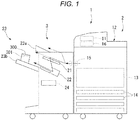
- FIG. 1 is a diagram illustrating an example of the entire configuration of an image forming system 1 according to an embodiment.
- FIG. 2 is a diagram illustrating an example of a functional configuration of the image forming system 1 illustrated in FIG. 1 .
- the image forming system 1 includes an image forming apparatus 2 and a sheet post-processing apparatus 3.
- the image forming apparatus 2 forms an image on a medium (in the following, referred to as a "sheet") having a sheet shape such as paper.
- the sheet post-processing apparatus 3 performs post-processing on a sheet conveyed from the image forming apparatus 2.
- the image forming apparatus 2 is provided with a control panel 11, a scanner unit 12, a printer unit 13, a paper feeding unit 14, a paper discharge unit 15, and an image forming control unit 16.
- the control panel 11 is provided with various keys receiving operations by a user. For example, the control panel 11 receives operation input by a user relating to a type of post-processing for a sheet.
- the control panel 11 sends information (including information about a type of a sheet) relating to the input type of post-processing to the sheet post-processing apparatus 3.
- a sheet is attached with a card.
- the card preserves its shape and returns to its original shape even when the card becomes bent.
- the sheet attached with the card is conveyed to the sheet post-processing apparatus 3 so that the surface of the sheet on which the card is attached faces upward.
- the card is separated by a card separation unit 300 provided in the sheet post-processing apparatus 3.
- the scanner unit 12 is provided with a reading unit which reads image information of an object to be copied.
- the scanner unit 12 sends the read image information to the printer unit 13.
- the printer unit 13 forms an output image (in the following, referred to as a "toner image") by developer such as a toner, based on image information transmitted from the scanner unit 12 or external equipment.
- the printer unit 13 transfers a toner image onto a surface of the sheet.
- the printer unit 13 applies heat and pressure to the toner image transferred onto the sheet to fix the toner image onto the sheet.
- the paper feeding unit 14 supplies the sheet to the printer unit 13 one by one at the timing when the printer unit 13 forms the toner image.
- the paper discharge unit 15 discharges the sheet from the printer unit 13 to the sheet post-processing apparatus 3.
- the image forming control unit 16 controls operations of the image forming apparatus 2 in its entirety. That is, the image forming control unit 16 controls the control panel 11, the scanner unit 12, the printer unit 13, the paper feeding unit 14, and the paper discharge unit 15.
- the image forming control unit 16 is formed with a control circuit including a central processing unit (CPU), a read only memory (ROM) and a random access memory (RAM).
- CPU central processing unit
- ROM read only memory
- RAM random access memory
- the sheet post-processing apparatus 3 is disposed to be adjacent to the image forming apparatus 2.
- the sheet post-processing apparatus 3 performs post-processing designated through the control panel 11 on the sheet conveyed from the image forming apparatus 2.
- post-processing is card separation processing, staple processing, or sort processing.
- the sheet post-processing apparatus 3 is provided with a standby unit 21, a processing unit 22, an ejection unit 23, a post-processing control unit 24, and the card separation unit 300.
- a finisher is an example of the sheet post-processing apparatus 3.
- the sheet post-processing apparatus 3 is one embodiment of the card separation apparatus.
- the standby unit 21 receives the sheet S conveyed from the image forming apparatus 2 onto a standby tray 41 (explained later) and temporarily holds the sheet S (see FIG. 3 ).
- the standby unit 21 makes a plurality of subsequent paper sheets S standby while post-processing for the preceding sheet S is performed by the processing unit 22.
- the standby unit 21 is provided above the processing unit 22.
- the standby tray 41 of the standby unit 21 is retreated from, for example, above the processing unit 22 so as to drop the sheet S being held by the standby unit 21 toward the processing unit 22.
- the processing unit 22 performs staple processing or sort processing on the sheet S. For example, the processing unit 22 aligns a plurality of sheets S. The processing unit 22 performs staple processing on the plurality of the aligned sheets S. With this, the plurality of the sheets S are bound.
- the processing unit 22 ejects the sheet S subjected to staple processing or sort processing to the ejection unit 23.
- the ejection unit 23 is provided with a fixed tray 23a and a movable tray 23b.
- the fixed tray 23a is provided at an upper portion of the sheet post-processing apparatus 3.
- the movable tray 23b is provided at a side portion of the sheet post-processing apparatus 3 such that the movable tray 23b can be movable in up and down direction.
- the sheet S subjected to staple processing or sort processing is ejected to the movable tray 23b.
- the card separation unit 300 is provided at an upper portion of the movable tray 23b.
- the card separation unit 300 includes a card tray 301, a bridge member 302, and a pair of sidewalls 303.
- the side walls 303 are disposed upright on an upper surface of the movable tray 23b. Upper side ends of the side walls 303 support the ends of the bridge member 302.
- the card separation unit 300 has an internal space M through which the sheet S can pass, that is surrounded by a lower surface 302b of the bridge member 302, side surfaces of a pair of sidewalls 303, which face each other, and the upper surface of the movable tray 23b.
- the card tray 301 is formed in a center of the bridge member 302.
- the card tray 301 has a card receiving portion 301 which has a concave shape to receive a card.
- the card separation unit 300 separates the card attached on the sheet S. Specifically, the sheet S is ejected so as to pass through the internal space M of the card separation unit 300. When a front end (a leading edge) of the sheet enters the internal space M of the card separation unit 300, the movable tray 23b is moved downward. When the movable tray 23b moves downward, a height difference between upper surface 44g ( Fig. 5 ) of an ejection port, at which the sheet is ejected from the sheet post-processing apparatus 3, and the internal space M of the card separation unit 300 is increased.
- the post-processing control unit 24 controls operations of the sheet post-processing apparatus 3 in its entirety. That is, the post-processing control unit 24 controls the standby unit 21, the processing unit 22, and the ejection unit 23. As illustrated in FIG. 2 , the post-processing control unit 24 controls a paddle unit 34 and the ejection roller 44a which will be described later.
- the post-processing control unit 24 is formed with a control circuit including the CPU, the ROM, and the RAM.
- FIG. 3 is a diagram schematically illustrating a configuration of the sheet post-processing apparatus 3 of the embodiment.
- the sheet post-processing apparatus 3 includes a conveying path 31 of the sheet S, a pair of inlet rollers 32a and 32b, a pair of outlet rollers 33a and 33b, the pair of ejection rollers 44a and 44b, the standby unit 21, the paddle unit 34, and the processing unit 22.
- a “sheet conveying direction” in the present specification means a conveying direction D (an entering direction of the sheet S into the standby tray 41) of the sheet S with respect to the standby tray 41 of the standby unit 21.
- an "upstream side” and a “downstream side” mean an upstream side and a downstream side in the sheet conveying direction D, respectively.
- a “front end portion” and a “rear end portion” mean an "end portion of the downstream side” and an "end portion of the upstream side” in the sheet conveying direction D, respectively.
- a direction which is substantially parallel to an upper surface of the standby tray 41 and substantially orthogonal to the sheet conveying direction D is referred to as a sheet width direction W.
- the conveying path 31 is provided inside the sheet post-processing apparatus 3.
- the conveying path 31 includes a sheet supply port 31p and a sheet ejection port 31d.
- the sheet supply port 31p faces the image forming apparatus 2 .
- the sheet S is supplied to the sheet supply port 31p from the image forming apparatus 2.
- the sheet ejection port 31d is positioned in the vicinity of the standby unit 21.
- the sheet S passing through the conveying path 31 is ejected onto the standby tray 41 of the standby unit 21 from the sheet ejection port 31d.
- the inlet rollers 32a and 32b are provided in the vicinity of the sheet supply port 31p.
- the inlet rollers 32a and 32b convey the sheet S supplied to the sheet supply port 31p toward the downstream side of the conveying path 31.
- the inlet rollers 32a and 32b convey the sheet S supplied to the sheet supply port 31p to the outlet rollers 33a and 33b.
- An inlet sensor 35 is provided in the vicinity of the inlet roller 32a and detects the sheet S passing through the sheet supply port 31p. For example, the inlet sensor 35 outputs a detection signal of a high level while detecting of the sheet S is performed whereas outputs a detection signal of a low level while detecting of the sheet S is not performed.
- the outlet rollers 33a and 33b are provided in the vicinity of the sheet ejection port 31d.
- the outlet rollers 33a and 33b receive the sheet S conveyed by the inlet rollers 32a and 32b.
- the outlet rollers 33a and 33b convey the sheet S from the sheet ejection port 31d to the standby unit 21.
- An outlet sensor 36 is provided in the vicinity of the outlet roller 33a and detects the sheet S passing through the sheet ejection port 31d. For example, the outlet sensor 36 outputs a detection signal of a high level while detecting of the sheet S is performed whereas outputs a detection signal of a low level while detecting of the sheet S is not performed.
- the standby unit 21 includes a standby tray (buffer tray) 41, a conveying guide 43, ejection rollers 44a and 44b, and an ejection sensor 46.
- the standby tray 41 is an example of a "second tray”.
- the rear end portion of the standby tray 41 is positioned in the vicinity of the outlet rollers 33a and 33b to receive the sheet from the outlet rollers 33a and 33b.
- the standby tray 41 makes a plurality of sheets S standby to be stacked while post-processing is performed by the processing unit 22.
- the standby tray 41 includes a bottom wall 45 which supports the sheet S from below.
- the bottom wall 45 is configured with, for example, two plate-like members arranged in parallel to the sheet conveying direction.
- the two plate-like members receive the sheet S on the surface thereof.
- the two plate-like members are retreated so as to be separated by being divided into the right-and-left direction, which is perpendicular to the sheet conveying direction D, to drop the held sheet S onto the processing tray 61.
- the ejection rollers 44a and 44b are provided in the vicinity of the ejection unit 23.
- the ejection rollers 44a and 44b receive the sheet S conveyed along the conveying guide 43.
- the ejection rollers 44a and 44b apply a conveying force to the sheet S to be conveyed to the ejection unit 23.
- the ejection roller 44a is a driving roller.
- the ejection roller 44b is a driven roller. In a case of a sheet attached with a card, the sheet is conveyed to the movable tray 23b.
- the ejection sensor 46 is provided in the vicinity of the ejection roller 44a and detects the front end of the sheet S passing through the ejection unit 23. For example, the ejection sensor 46 outputs a detection signal of a high level while the sheet S is detected, and outputs a detection signal of a low level while the sheet S is not detected.
- the paddle unit 34 is provided between the standby tray 41 and the processing tray 61.
- the paddle unit 34 rotates so as to push the sheet S toward the processing tray 61. Furthermore, the paddle unit 34 conveys the sheet S dropped onto the processing tray 61 toward a stapler 62 which will be described later.
- the paddle unit 34 includes a rotation shaft 49, a rotation body 50, a plurality of first paddles 51 and a plurality of second paddles 52.
- the processing unit 22 includes the processing tray 61, the stapler 62, conveying rollers 63a and 63b, a conveying belt 64, and a restraining pawl 65.
- the processing tray 61 is an example of a "first tray”.
- the processing tray 61 is provided below the standby tray 41.
- a plurality of sheets S conveyed to the processing tray 61 are aligned by an alignment plate or the like in the sheet width direction W and the sheet conveying direction D.
- the stapler 62 is provided at an end portion of the processing tray 61.
- the stapler 62 performs staple processing (binding) on a bundle of a predetermined number of sheets S positioned on the processing tray 61.
- the conveying rollers 63a and 63b are disposed at predetermined intervals in the sheet conveying direction D.
- the conveying belt 64 is stretched between the conveying rollers 63a and 63b.
- the conveying belt 64 is rotated by being synchronized with the conveying rollers 63a and 63b.
- the conveying belt 64 conveys the sheet S between the stapler 62 and the ejection unit 23.
- the post-processing control unit 24 of the sheet post-processing apparatus 3 controls the conveying speed of the sheet S by controlling the number of rotations of the outlet rollers 33a and 33b when ejecting the sheet S to the processing tray 61.
- conveying speed control of the sheet S in the post-processing control unit 24 in a first exemplary embodiment.
- the sheet S is assumed to be in a state of being ejected directly onto the processing tray 61 without passing through the standby tray 41, on the premise that the conveying speed control of the sheet S is performed in first exemplary embodiment.
- a restraining hook 65 is a pushing-out member which is provided on the conveying belt 64 and driven integrally with the conveying belt 64.
- the restraining hook 65 is driven together with the conveying belt 64 to move the sheet S on the processing tray 61 to the downstream side in the conveying direction.
- the restraining hook 65 is retreated from a sheet placement surface of the processing tray 61.
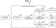
- FIG. 4 is diagram illustrating functional blocks relating to control of sheet separation processing in the post-processing control unit 24 of the exemplary embodiment.
- the post-processing control unit 24 is provided with a communication unit 241, a sheet information acquisition unit 242, a sensor information acquisition unit 243, a rotation control unit 244, and a movable tray control unit 245.
- the communication unit 241 performs communication with the control panel 11 of the image forming apparatus 2.
- the sheet information acquisition unit 242 acquires information of an operation input indicating a type of post-processing selected by a user from the control panel 11 through the communication unit 241 and information about a type of the sheet S to be subjected to post-processing.
- the information about the type of the sheet S includes information relating to a size of the sheet S (information such as A4 or A3), information about basis weight of the sheet S, information about a material of the sheet S, information of whether a card is attached onto a sheet or not, and the like.
- Basis weight of the sheet S is weight of the sheet S g/m 2 per square meter. When the card is attached to the sheet, information about a position on the sheet where the card is attached and the number of cards may be included.
- the sensor information acquisition unit 243 acquires a detection signal according to detection of the sheet S, which passes through the ejection unit 23, from the ejection sensor 46.
- a detection signal of a high level indicating that the sheet S is detected is referred to as an ON signal and a detection signal of a low level indicating that the sheet S is not detected is referred to as an OFF signal.
- the rotation control unit 244 controls rotation of the ejection rollers 44a and 44b conveying the sheet S based on information about the sheet S acquired by the sheet information acquisition unit 242 and the detection signal acquired by the sensor information acquisition unit 243.
- the rotation control unit 244 controls the number of rotations of a driving motor which rotates the ejection rollers 44a and 44b by a pulse rate (pps: pulses per second). That is, the rotation control unit 244 controls the rotational speed of the ejection rollers 44a and 44b so as to control the conveying speed of the sheet S.
- the rotation control unit 244 sets a first speed of the sheet S as v1 (pps) and sets a second speed as v2 (pps) based on, for example, information about the sheet S.
- the first speed v1 (pps) and the second speed v2 (pps) of the sheet S are just examples and the rotation control unit 244 may set an arbitrary value according to the size and basis weight of the sheet S, as the conveying speed.
- the conveying speed of the sheet S there are a first speed at which the sheet S is conveyed in the conveying path 31 and a second speed which is suitable for ejecting the sheet S to the processing tray 61 (where first speed > second speed) .
- the speed suitable for ejecting the sheet S to the processing tray 61 is a speed at which the ejected sheet S lands on a predetermined position of the processing tray 61. That is, the post-processing control unit 24 controls such that the sheet S is conveyed in the conveying path at the first speed or the second speed.
- the rotation control unit 244 reduces the conveying speed before the front end portion of the sheet S collides with the processing tray 61 based on the timing at which the detection signal becomes the ON signal and the size of the sheet S.
- the timing at which the detection becomes the ON signal is the timing at which the front end portion of the sheet S passing through the sheet ejection port 31d.
- the expression of "before the front end portion of the sheet S collides to the processing tray 61" means a period of time which is before the front end portion of the sheet S comes in contact with the processing tray 61 and after the front end portion of the sheet S passed through the sheet ejection port 31d.
- a conveying amount extending from the sheet ejection port 31d to a position until right before the front end portion of the sheet S collides to the processing tray 61 is set as a first conveying amount.
- the rotation control unit 244 monitors the conveying amount of the sheet S from a time point at which the front end portion of the sheet S passes through the sheet ejection port 31d and decelerates at a time point at which the sheet S is conveyed by the first conveying amount.
- the rotation control unit 244 also sets the first conveying amount when setting the first speed and the second speed based on information about the sheet S.
- the movable tray control unit 245 controls a vertical movement of the movable tray 23b based on information about the sheet S acquired by the sheet information acquisition unit 242 and the detection signal acquired by the sensor information acquisition unit 243.
- the movable tray control unit 245 controls the movable tray 23b to be moved down to a lower portion of the sheet post-processing apparatus 3.
- the movable tray control unit 245 determines the timing at which the movable tray 23b is to be moved down to the lower portion of the sheet post-processing apparatus 3 based on information about the sheet S.
- FIG. 5 is a diagram schematically illustrating a configuration of the card separation unit 300 of the embodiment.
- the card separation unit 300 includes the card tray 301.
- the card separation unit 300 is provided on the movable tray 23b.
- the sheet S is ejected from the sheet post-processing apparatus 3 so that the surface of the sheet on which the card is attached faces upward (face up manner) due to the rotation of the ejection rollers 44a and 44b (see Fig. 3 ) .
- the movable tray 23b is moved down to the lower portion at a predetermined timing such that a card 401 separated from the sheet is accumulated in the card tray 301.
- a plurality of the card trays 301 may be provided.
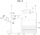
- FIG. 6 to FIG. 9 are diagrams schematically illustrating a flow of card separation processing according to the embodiment.
- FIG. 6 is a diagram illustrating a state in which a sheet S is present in the processing tray 61 of the embodiment.
- the sheet S disposed in the processing tray 61 is conveyed to the ejection unit 23 by a conveying force applied from the ejection rollers 44a and 44b.
- the ejection sensor 46 detects the front end portion of the sheet S passing through the ejection unit 23.
- the ejection sensor 46 outputs the detection signal of the high level while the sheet S is detected.
- FIG. 7 is a diagram illustrating a state in which ejection from the processing tray 61 to the movable tray 23b of the embodiment is started.
- the front end portion of the sheet S ejected onto the movable tray 23b is conveyed into the lower portion of the card separation unit 300.
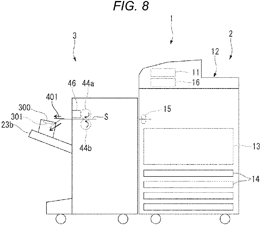
- FIG. 8 is a diagram illustrating a state in which the movable tray 23b of the embodiment is made to descend such that the sheet S is deformed.
- the movable tray 23b descends based on the instruction of the movable tray control unit 245.
- the front end of the sheet S is pushed downward by the card separation unit 300 and is bent.
- the card 401 is separated from the bent sheet.
- the predetermined length is a length corresponding to a downward-push degree of the sheet S when the movable tray 23b descends.
- the predetermined length may differ according to the type of the sheet.
- FIG. 9 is a diagram illustrating a state in which ejection of the sheet S is completed.
- the ejection rollers 44a and 44b further convey the sheet S in a state where the movable tray 23b is moved down to the lower portion and the sheet S is downwardly bent.
- the sheet S is dropped onto the upper portion of the movable tray 23b.
- the card 401 is completely separated from the sheet S.
- the card 401 separated from the sheet S drops onto the card tray 301 included in the card separation unit 300 and card separation processing is ended.
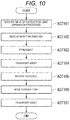
- FIG. 10 is a flowchart depicting a flow of card separation processing according to an embodiment.
- the control panel 11 of the image forming apparatus 2 receives input of instruction card separation processing from a user (ACT 101) .
- the control panel 11 receives information about the sheet from the user (ACT 102) .
- the printer unit 13 of the image forming apparatus 2 forms an image on the card attached to the sheet (ACT 103) .
- the sheet on which an image is formed is supplied to the sheet post-processing apparatus 3 and is conveyed in the conveying path 31 (ACT 104) .
- the sensor information acquisition unit 243 of the sheet post-processing apparatus 3 receives the ON signal from the ejection sensor 46 (ACT 105).
- the movable tray control unit 245 moves down the movable tray 23b to the lower portion at a predetermined timing based on information about the sheet received from the control panel 11 and the ON signal received from the sensor information acquisition unit 243 (ACT 106) .
- the ejection rollers 44a and 44b rotate until the sheet is entirely conveyed (ACT 107) .
- the processing is ended.
- the movable tray 23b descends at a predetermined timing so as to make it possible for the card separation unit 300 to separate the card attached to the sheet.
- the sheet is further conveyed in a state of being separated such that the card is completely separated from the sheet. Accordingly, the user may acquire the card from the sheet more efficiently.
- processing for separating the card from the sheet by allowing the ejection rollers 44a and 44b to convey the sheet was described in detail.
- a mechanism used for conveying the sheet in order to separate the card is not limited to the ejection rollers 44a and 44b.
- a mechanism which applies a force pushing out the sheet from the rear may be included, instead of the ejection rollers 44a and 44b.
- the processing unit 22 may drive the conveying belt 64 in a state where the sheet is pushed by the paddle unit 34 so as to cause the restraining hook 65 to move the sheet.
- the conveying belt 64 is driven so as to cause the restraining hook 65 to abut on the edge of the sheet on the upstream side in the conveying direction.
- the restraining hook 65 pushes out the edge of the sheet on the upstream side in the conveying direction toward the downstream side in conveying direction.
- the restraining hook 65 pushes out the sheet so as to be conveyed to the movable tray 23b such that the sheet is moved down to the lower portion of the card separation unit 300.
- control that causes the ejection sensor 46 to detect the conveyed sheet so as to move the movable tray 23b to the lower portion was described in detail.
- control that causes the movable tray 23b to be moved down to lower portion in order to separate the card is not limited to the configuration in which the sheet is detected by the ejection sensor 46.
- control that causes the movable tray 23b to be moved down to the lower portion may be performed, after a predetermined time elapses from image formation on the sheet.
- the predetermined time is, for example, the time required for allowing the conveyed sheet to be entered into the lower portion of the card separation unit 300 by a predetermined length.
- the predetermined time is determined based on information about the sheet received from the control panel 11 and the conveying speed of the sheet.
- the card separation unit 300 may include a plurality of card trays 301.
Landscapes
- Engineering & Computer Science (AREA)
- Mechanical Engineering (AREA)
- Pile Receivers (AREA)
Abstract
A card separation apparatus includes a movable tray (23b) having a surface onto which a sheet (S) is conveyed after a card (401) has been separated from the sheet, and a card separation unit (300) mounted on the surface for movement with the movable tray, the card separation unit having an opening through which the sheet is conveyed, and a controller (24) configured to send an instruction to the movable tray to be moved at a predetermined timing after a leading edge of the sheet to which the card is attached enters the opening, so as to cause the sheet to be initially separated from the card.


Description
- Embodiments described herein relate generally to a card separation apparatus and a card separation method.
- A sheet which is subjected to being conveyed in an image forming apparatus is assumed to have a minimum size. A card-sized sheet (hereinafter, referred to as "card"), which has a size smaller than the minimum size, cannot be conveyed in the image forming apparatus. For that reason, in order to form an image on the card by the image forming apparatus, a user needs to attach the card onto a sheet having at least the minimum size capable of being conveyed in the image forming apparatus. After the sheet on which the card is attached is ejected from the image forming apparatus, the card needs to be manually separated by the user.
- One of the objects of the present invention is to improve prior art techniques and overcome at least some of the prior art problems as for instance above illustrated.
- According to a first aspect of the present invention, it is provided a card separation apparatus comprising:
- a movable tray having a surface onto which a sheet is conveyed after a card has been separated from the sheet, and a card separation unit mounted on the surface for movement with the movable tray, the card separation unit having an opening through which the sheet is conveyed; and
- a controller configured to send an instruction to the movable tray to be moved at a predetermined timing after a leading edge of the sheet to which the card is attached enters the opening, so as to cause the sheet to be initially separated from the card.
- Optionally, in the apparatus according to the first aspect, the movable tray is movable up and down, and the controller controls the movable tray to move down at the predetermined timing.
- Optionally, in the apparatus according to the first aspect, the controller controls the movable tray to move down at the predetermined timing and stay down until the card has separated completely from the sheet and the sheet is conveyed onto the surface of the movable tray.
- Optionally, in the apparatus according to the first aspect, the card separation unit includes a card tray at an upper surface of the card separation unit, the card tray being positioned to receive the card that is separated from the sheet by the card separation unit and shaped to hold the separated card.
- Optionally, in the apparatus according to the first aspect, the card tray has a concave portion and the separated card is received into the concave portion.
- Optionally, the apparatus according to the first aspect further comprises a conveying roller configured to convey the sheet to the movable tray and through the opening of the card separation unit.
- Optionally, the apparatus according to the first aspect further comprises an ejection sensor configured to detect a sheet conveyed by the conveying roller, wherein the controller determines the predetermined timing based on detection signals from the ejection sensor.
- Optionally, the apparatus according to the first aspect further comprises a restraining pawl configured to discharge the sheet through the opening of the card separation unit.
- Optionally, in the apparatus according to the first aspect, the controller is configured to determine the predetermined timing based on information about the sheet and a conveying speed of the sheet.
- Optionally, the apparatus according to the first aspect further comprises a communication unit configured to receive the information about the sheet from outside of the card separation apparatus.
- Optionally, in the apparatus according to the first aspect, the information about the sheet includes size information of the sheet.
- According to a second aspect of the present invention, it is provided a card separation method comprising:
- conveying a sheet having a card attached thereto towards a movable tray having a surface onto which the sheet is to be conveyed after the card is separated from the sheet and a card separation unit mounted on the surface for movement with the movable tray, the card separation unit having an opening through which the sheet is to be conveyed; and
- at a predetermined timing after a leading edge of the sheet enters the opening, lowering the movable tray and causing the sheet to be initially separated from the card.
- Optionally, the method according to the second aspect further comprises maintaining the movable tray at the lowered position until the card has separated completely from the sheet and the sheet is conveyed onto the surface of the movable tray.
- Optionally, in the method according to the second aspect, the card separation unit includes a card tray at an upper surface of the card separation unit, the card tray being positioned to receive the card that is separated from the sheet by the card separation unit and shaped to hold the separated card.
- Optionally, in the method according to the second aspect, the card tray has a concave portion and the separated card is received into the concave portion.
- Optionally, the method according to the second aspect further comprises detecting a sheet conveyed by the conveying roller using a sensor that is placed at an upstream side of the card separation unit, wherein the predetermined timing is determined based on detection signals from the sensor.
- Optionally, the method according to the second aspect further comprises discharging the sheet through the opening of the card separation unit using a restraining pawl.
- Optionally, the method according to the second aspect further comprises determining the predetermined timing based on information about the sheet and a conveying speed of the sheet.
- Optionally, in the method according to the second aspect, the information about the sheet includes size information of the sheet.
- Optionally, in the method according to the second aspect, the information about the sheet further includes a position of the card on the sheet.
-
-
FIG. 1 illustrates a diagram of an image forming system according to an embodiment. -
FIG. 2 illustrates a diagram of a functional configuration of the image forming system illustrated inFIG. 1 . -
FIG. 3 illustrates a schematic diagram of a configuration of a sheet post-processing apparatus of the embodiment. -
FIG. 4 illustrates a functional block diagram relating to control of sheet separation processing in a post-processing control unit of the embodiment. -
FIG. 5 illustrates a schematic diagram of a configuration of a card separation unit of the embodiment. -
FIG. 6 illustrates a diagram of a state in which a sheet is present in a processing tray. -
FIG. 7 illustrates a diagram of a state in which ejection from the processing tray to a movable tray is started. -
FIG. 8 illustrates a diagram of a state in which the movable tray is made to descend such that the sheet is deformed. -
FIG. 9 illustrates a diagram of a state in which ejection of the sheet is completed. -
FIG. 10 is a flowchart depicting a flow of card separation processing according to an embodiment. - In general, according to one embodiment, a card separation apparatus includes a movable tray having a surface onto which a sheet is conveyed after a card has been separated from the sheet, and a card separation unit mounted on the surface for movement with the movable tray, the card separation unit having an opening through which the sheet is conveyed, and a controller configured to send an instruction to the movable tray to be moved at a predetermined timing after a leading edge of the sheet to which the card is attached enters the opening, so as to cause the sheet to be initially separated from the card.
- In the following, an image forming system provided with an image forming apparatus and a sheet post-processing apparatus of the embodiments will be described with reference to the accompanying drawings.
-
FIG. 1 is a diagram illustrating an example of the entire configuration of an image forming system 1 according to an embodiment.FIG. 2 is a diagram illustrating an example of a functional configuration of the image forming system 1 illustrated inFIG. 1 . The image forming system 1 includes animage forming apparatus 2 and asheet post-processing apparatus 3. Theimage forming apparatus 2 forms an image on a medium (in the following, referred to as a "sheet") having a sheet shape such as paper. Thesheet post-processing apparatus 3 performs post-processing on a sheet conveyed from theimage forming apparatus 2. - The
image forming apparatus 2 is provided with acontrol panel 11, ascanner unit 12, aprinter unit 13, apaper feeding unit 14, apaper discharge unit 15, and an image formingcontrol unit 16. Thecontrol panel 11 is provided with various keys receiving operations by a user. For example, thecontrol panel 11 receives operation input by a user relating to a type of post-processing for a sheet. Thecontrol panel 11 sends information (including information about a type of a sheet) relating to the input type of post-processing to thesheet post-processing apparatus 3. A sheet is attached with a card. The card preserves its shape and returns to its original shape even when the card becomes bent. The sheet attached with the card is conveyed to thesheet post-processing apparatus 3 so that the surface of the sheet on which the card is attached faces upward. The card is separated by acard separation unit 300 provided in thesheet post-processing apparatus 3. - The
scanner unit 12 is provided with a reading unit which reads image information of an object to be copied. Thescanner unit 12 sends the read image information to theprinter unit 13. Theprinter unit 13 forms an output image (in the following, referred to as a "toner image") by developer such as a toner, based on image information transmitted from thescanner unit 12 or external equipment. Theprinter unit 13 transfers a toner image onto a surface of the sheet. Theprinter unit 13 applies heat and pressure to the toner image transferred onto the sheet to fix the toner image onto the sheet. Thepaper feeding unit 14 supplies the sheet to theprinter unit 13 one by one at the timing when theprinter unit 13 forms the toner image. Thepaper discharge unit 15 discharges the sheet from theprinter unit 13 to the sheetpost-processing apparatus 3. - The image forming
control unit 16 controls operations of theimage forming apparatus 2 in its entirety. That is, the image formingcontrol unit 16 controls thecontrol panel 11, thescanner unit 12, theprinter unit 13, thepaper feeding unit 14, and thepaper discharge unit 15. The image formingcontrol unit 16 is formed with a control circuit including a central processing unit (CPU), a read only memory (ROM) and a random access memory (RAM). - Next, the sheet
post-processing apparatus 3 will be described. - First, the entire configuration of the sheet
post-processing apparatus 3 will be described. As illustrated inFIG. 1 , the sheetpost-processing apparatus 3 is disposed to be adjacent to theimage forming apparatus 2. The sheetpost-processing apparatus 3 performs post-processing designated through thecontrol panel 11 on the sheet conveyed from theimage forming apparatus 2. For example, post-processing is card separation processing, staple processing, or sort processing. The sheetpost-processing apparatus 3 is provided with astandby unit 21, aprocessing unit 22, anejection unit 23, apost-processing control unit 24, and thecard separation unit 300. A finisher is an example of the sheetpost-processing apparatus 3. The sheetpost-processing apparatus 3 is one embodiment of the card separation apparatus. - The
standby unit 21 receives the sheet S conveyed from theimage forming apparatus 2 onto a standby tray 41 (explained later) and temporarily holds the sheet S (seeFIG. 3 ). For example, thestandby unit 21 makes a plurality of subsequent paper sheets S standby while post-processing for the preceding sheet S is performed by theprocessing unit 22. Thestandby unit 21 is provided above theprocessing unit 22. When the sheet, which is processed by theprocessing unit 22, is ejected from theejection unit 23, thestandby tray 41 of thestandby unit 21 is retreated from, for example, above theprocessing unit 22 so as to drop the sheet S being held by thestandby unit 21 toward theprocessing unit 22. - The
processing unit 22 performs staple processing or sort processing on the sheet S. For example, theprocessing unit 22 aligns a plurality of sheets S. Theprocessing unit 22 performs staple processing on the plurality of the aligned sheets S. With this, the plurality of the sheets S are bound. Theprocessing unit 22 ejects the sheet S subjected to staple processing or sort processing to theejection unit 23. Theejection unit 23 is provided with a fixedtray 23a and amovable tray 23b. The fixedtray 23a is provided at an upper portion of the sheetpost-processing apparatus 3. Themovable tray 23b is provided at a side portion of the sheetpost-processing apparatus 3 such that themovable tray 23b can be movable in up and down direction. The sheet S subjected to staple processing or sort processing is ejected to themovable tray 23b. - The
card separation unit 300 is provided at an upper portion of themovable tray 23b. Thecard separation unit 300 includes acard tray 301, abridge member 302, and a pair ofsidewalls 303. Theside walls 303 are disposed upright on an upper surface of themovable tray 23b. Upper side ends of theside walls 303 support the ends of thebridge member 302. Thecard separation unit 300 has an internal space M through which the sheet S can pass, that is surrounded by alower surface 302b of thebridge member 302, side surfaces of a pair ofsidewalls 303, which face each other, and the upper surface of themovable tray 23b. Thecard tray 301 is formed in a center of thebridge member 302. Thecard tray 301 has acard receiving portion 301 which has a concave shape to receive a card. - The
card separation unit 300 separates the card attached on the sheet S. Specifically, the sheet S is ejected so as to pass through the internal space M of thecard separation unit 300. When a front end (a leading edge) of the sheet enters the internal space M of thecard separation unit 300, themovable tray 23b is moved downward. When themovable tray 23b moves downward, a height difference betweenupper surface 44g (Fig. 5 ) of an ejection port, at which the sheet is ejected from the sheetpost-processing apparatus 3, and the internal space M of thecard separation unit 300 is increased. By this movement, an upper surface of the front end portion of the sheet, which is not supported by theupper surface 44g of the ejection port, is pushed down and deformed by thelower surface 302b of thebridge member 302 which moves downward according to an increase in the height difference. As a result, a portion of the card becomes separated from the sheet as the sheet S is conveyed. The sheet is further conveyed while a portion of the card is being separated such that the card is entirely separated from the sheet. The separated card is received on thecard receiving portion 301 of thecard tray 301 included in thecard separation unit 300. - The
post-processing control unit 24 controls operations of the sheetpost-processing apparatus 3 in its entirety. That is, thepost-processing control unit 24 controls thestandby unit 21, theprocessing unit 22, and theejection unit 23. As illustrated inFIG. 2 , thepost-processing control unit 24 controls apaddle unit 34 and theejection roller 44a which will be described later. Thepost-processing control unit 24 is formed with a control circuit including the CPU, the ROM, and the RAM. - Next, configurations of respective components of the sheet
post-processing apparatus 3 of embodiment will be described in detail.FIG. 3 is a diagram schematically illustrating a configuration of the sheetpost-processing apparatus 3 of the embodiment. As illustrated inFIG. 3 , the sheetpost-processing apparatus 3 includes a conveyingpath 31 of the sheet S, a pair ofinlet rollers outlet rollers ejection rollers standby unit 21, thepaddle unit 34, and theprocessing unit 22. - A "sheet conveying direction" in the present specification means a conveying direction D (an entering direction of the sheet S into the standby tray 41) of the sheet S with respect to the
standby tray 41 of thestandby unit 21. In the present specification, an "upstream side" and a "downstream side" mean an upstream side and a downstream side in the sheet conveying direction D, respectively. In the present specification, a "front end portion" and a "rear end portion" mean an "end portion of the downstream side" and an "end portion of the upstream side" in the sheet conveying direction D, respectively. Also, in the present specification, a direction which is substantially parallel to an upper surface of thestandby tray 41 and substantially orthogonal to the sheet conveying direction D is referred to as a sheet width direction W. - The conveying
path 31 is provided inside the sheetpost-processing apparatus 3. The conveyingpath 31 includes asheet supply port 31p and asheet ejection port 31d. Thesheet supply port 31p faces theimage forming apparatus 2 . The sheet S is supplied to thesheet supply port 31p from theimage forming apparatus 2. On the other hand, thesheet ejection port 31d is positioned in the vicinity of thestandby unit 21. The sheet S passing through the conveyingpath 31 is ejected onto thestandby tray 41 of thestandby unit 21 from thesheet ejection port 31d. - The
inlet rollers sheet supply port 31p. Theinlet rollers sheet supply port 31p toward the downstream side of the conveyingpath 31. For example, theinlet rollers sheet supply port 31p to theoutlet rollers inlet sensor 35 is provided in the vicinity of theinlet roller 32a and detects the sheet S passing through thesheet supply port 31p. For example, theinlet sensor 35 outputs a detection signal of a high level while detecting of the sheet S is performed whereas outputs a detection signal of a low level while detecting of the sheet S is not performed. - The
outlet rollers sheet ejection port 31d. Theoutlet rollers inlet rollers outlet rollers sheet ejection port 31d to thestandby unit 21. Anoutlet sensor 36 is provided in the vicinity of theoutlet roller 33a and detects the sheet S passing through thesheet ejection port 31d. For example, theoutlet sensor 36 outputs a detection signal of a high level while detecting of the sheet S is performed whereas outputs a detection signal of a low level while detecting of the sheet S is not performed. - Next, the
standby unit 21 will be described. Thestandby unit 21 includes a standby tray (buffer tray) 41, a conveyingguide 43,ejection rollers ejection sensor 46. Thestandby tray 41 is an example of a "second tray". The rear end portion of thestandby tray 41 is positioned in the vicinity of theoutlet rollers outlet rollers standby tray 41 makes a plurality of sheets S standby to be stacked while post-processing is performed by theprocessing unit 22. Thestandby tray 41 includes abottom wall 45 which supports the sheet S from below. Thebottom wall 45 is configured with, for example, two plate-like members arranged in parallel to the sheet conveying direction. The two plate-like members receive the sheet S on the surface thereof. The two plate-like members are retreated so as to be separated by being divided into the right-and-left direction, which is perpendicular to the sheet conveying direction D, to drop the held sheet S onto theprocessing tray 61. - The
ejection rollers ejection unit 23. Theejection rollers guide 43. Theejection rollers ejection unit 23. Theejection roller 44a is a driving roller. On the other hand, theejection roller 44b is a driven roller. In a case of a sheet attached with a card, the sheet is conveyed to themovable tray 23b. Theejection sensor 46 is provided in the vicinity of theejection roller 44a and detects the front end of the sheet S passing through theejection unit 23. For example, theejection sensor 46 outputs a detection signal of a high level while the sheet S is detected, and outputs a detection signal of a low level while the sheet S is not detected. - The
paddle unit 34 is provided between thestandby tray 41 and theprocessing tray 61. When the sheet S is conveyed from thestandby tray 41 toward theprocessing tray 61, thepaddle unit 34 rotates so as to push the sheet S toward theprocessing tray 61. Furthermore, thepaddle unit 34 conveys the sheet S dropped onto theprocessing tray 61 toward astapler 62 which will be described later. Thepaddle unit 34 includes arotation shaft 49, arotation body 50, a plurality offirst paddles 51 and a plurality ofsecond paddles 52. - Next, the
processing unit 22 will be described. Theprocessing unit 22 includes theprocessing tray 61, thestapler 62, conveyingrollers belt 64, and a restrainingpawl 65. Theprocessing tray 61 is an example of a "first tray". Theprocessing tray 61 is provided below thestandby tray 41. A plurality of sheets S conveyed to theprocessing tray 61 are aligned by an alignment plate or the like in the sheet width direction W and the sheet conveying direction D. Thestapler 62 is provided at an end portion of theprocessing tray 61. Thestapler 62 performs staple processing (binding) on a bundle of a predetermined number of sheets S positioned on theprocessing tray 61. - The conveying
rollers belt 64 is stretched between the conveyingrollers belt 64 is rotated by being synchronized with the conveyingrollers belt 64 conveys the sheet S between thestapler 62 and theejection unit 23. - The
post-processing control unit 24 of the sheetpost-processing apparatus 3 controls the conveying speed of the sheet S by controlling the number of rotations of theoutlet rollers processing tray 61. In the following, description will be made on conveying speed control of the sheet S in thepost-processing control unit 24 in a first exemplary embodiment. The sheet S is assumed to be in a state of being ejected directly onto theprocessing tray 61 without passing through thestandby tray 41, on the premise that the conveying speed control of the sheet S is performed in first exemplary embodiment. - A restraining
hook 65 is a pushing-out member which is provided on the conveyingbelt 64 and driven integrally with the conveyingbelt 64. The restraininghook 65 is driven together with the conveyingbelt 64 to move the sheet S on theprocessing tray 61 to the downstream side in the conveying direction. When the sheet S is conveyed to theprocessing tray 61, the restraininghook 65 is retreated from a sheet placement surface of theprocessing tray 61. -
FIG. 4 is diagram illustrating functional blocks relating to control of sheet separation processing in thepost-processing control unit 24 of the exemplary embodiment. As illustrated inFIG. 4 , thepost-processing control unit 24 is provided with acommunication unit 241, a sheetinformation acquisition unit 242, a sensorinformation acquisition unit 243, arotation control unit 244, and a movabletray control unit 245. - The
communication unit 241 performs communication with thecontrol panel 11 of theimage forming apparatus 2. The sheetinformation acquisition unit 242 acquires information of an operation input indicating a type of post-processing selected by a user from thecontrol panel 11 through thecommunication unit 241 and information about a type of the sheet S to be subjected to post-processing. The information about the type of the sheet S includes information relating to a size of the sheet S (information such as A4 or A3), information about basis weight of the sheet S, information about a material of the sheet S, information of whether a card is attached onto a sheet or not, and the like. Basis weight of the sheet S is weight of the sheet S g/m2 per square meter. When the card is attached to the sheet, information about a position on the sheet where the card is attached and the number of cards may be included. - The sensor
information acquisition unit 243 acquires a detection signal according to detection of the sheet S, which passes through theejection unit 23, from theejection sensor 46. In the following description, a detection signal of a high level indicating that the sheet S is detected is referred to as an ON signal and a detection signal of a low level indicating that the sheet S is not detected is referred to as an OFF signal. - The
rotation control unit 244 controls rotation of theejection rollers information acquisition unit 242 and the detection signal acquired by the sensorinformation acquisition unit 243. - The
rotation control unit 244 controls the number of rotations of a driving motor which rotates theejection rollers rotation control unit 244 controls the rotational speed of theejection rollers rotation control unit 244 sets a first speed of the sheet S as v1 (pps) and sets a second speed as v2 (pps) based on, for example, information about the sheet S. The first speed v1 (pps) and the second speed v2 (pps) of the sheet S are just examples and therotation control unit 244 may set an arbitrary value according to the size and basis weight of the sheet S, as the conveying speed. - As the conveying speed of the sheet S, there are a first speed at which the sheet S is conveyed in the conveying
path 31 and a second speed which is suitable for ejecting the sheet S to the processing tray 61 (where first speed > second speed) . The speed suitable for ejecting the sheet S to theprocessing tray 61 is a speed at which the ejected sheet S lands on a predetermined position of theprocessing tray 61. That is, thepost-processing control unit 24 controls such that the sheet S is conveyed in the conveying path at the first speed or the second speed. Therotation control unit 244 reduces the conveying speed before the front end portion of the sheet S collides with theprocessing tray 61 based on the timing at which the detection signal becomes the ON signal and the size of the sheet S. The timing at which the detection becomes the ON signal is the timing at which the front end portion of the sheet S passing through thesheet ejection port 31d. The expression of "before the front end portion of the sheet S collides to theprocessing tray 61" means a period of time which is before the front end portion of the sheet S comes in contact with theprocessing tray 61 and after the front end portion of the sheet S passed through thesheet ejection port 31d. - It is possible to predict how far the front end portion of the sheet S is conveyed from the
sheet ejection port 31d and when the front end portion of the sheet S collides to theprocessing tray 61, based on the size and basis weight of the sheet S and a distance from thesheet ejection port 31d to theprocessing tray 61. Here, a conveying amount extending from thesheet ejection port 31d to a position until right before the front end portion of the sheet S collides to theprocessing tray 61 is set as a first conveying amount. Therotation control unit 244 monitors the conveying amount of the sheet S from a time point at which the front end portion of the sheet S passes through thesheet ejection port 31d and decelerates at a time point at which the sheet S is conveyed by the first conveying amount. Therotation control unit 244 also sets the first conveying amount when setting the first speed and the second speed based on information about the sheet S. - The movable
tray control unit 245 controls a vertical movement of themovable tray 23b based on information about the sheet S acquired by the sheetinformation acquisition unit 242 and the detection signal acquired by the sensorinformation acquisition unit 243. - When the ON signal generated by the
ejection sensor 46 is received from the sensorinformation acquisition unit 243, the movabletray control unit 245 controls themovable tray 23b to be moved down to a lower portion of the sheetpost-processing apparatus 3. The movabletray control unit 245 determines the timing at which themovable tray 23b is to be moved down to the lower portion of the sheetpost-processing apparatus 3 based on information about the sheet S. -
FIG. 5 is a diagram schematically illustrating a configuration of thecard separation unit 300 of the embodiment. As illustrated inFIG. 5 , thecard separation unit 300 includes thecard tray 301. Thecard separation unit 300 is provided on themovable tray 23b. The sheet S is ejected from the sheetpost-processing apparatus 3 so that the surface of the sheet on which the card is attached faces upward (face up manner) due to the rotation of theejection rollers Fig. 3 ) . Themovable tray 23b is moved down to the lower portion at a predetermined timing such that acard 401 separated from the sheet is accumulated in thecard tray 301. A plurality of thecard trays 301 may be provided. -
FIG. 6 to FIG. 9 are diagrams schematically illustrating a flow of card separation processing according to the embodiment.FIG. 6 is a diagram illustrating a state in which a sheet S is present in theprocessing tray 61 of the embodiment. The sheet S disposed in theprocessing tray 61 is conveyed to theejection unit 23 by a conveying force applied from theejection rollers ejection sensor 46 detects the front end portion of the sheet S passing through theejection unit 23. Theejection sensor 46 outputs the detection signal of the high level while the sheet S is detected. -
FIG. 7 is a diagram illustrating a state in which ejection from theprocessing tray 61 to themovable tray 23b of the embodiment is started. The front end portion of the sheet S ejected onto themovable tray 23b is conveyed into the lower portion of thecard separation unit 300. -
FIG. 8 is a diagram illustrating a state in which themovable tray 23b of the embodiment is made to descend such that the sheet S is deformed. When the sheet S is conveyed into the lower portion of thecard separation unit 300 from the front end portion of the sheet S by a predetermined length, themovable tray 23b descends based on the instruction of the movabletray control unit 245. When themovable tray 23b descends, the front end of the sheet S is pushed downward by thecard separation unit 300 and is bent. When the sheet is bent, thecard 401 is separated from the bent sheet. The predetermined length is a length corresponding to a downward-push degree of the sheet S when themovable tray 23b descends. The predetermined length may differ according to the type of the sheet. -
FIG. 9 is a diagram illustrating a state in which ejection of the sheet S is completed. Theejection rollers movable tray 23b is moved down to the lower portion and the sheet S is downwardly bent. When the sheet S is entirely conveyed to theejection rollers movable tray 23b. When the sheet S is entirely conveyed to theejection rollers card 401 is completely separated from the sheet S. Thecard 401 separated from the sheet S drops onto thecard tray 301 included in thecard separation unit 300 and card separation processing is ended. -
FIG. 10 is a flowchart depicting a flow of card separation processing according to an embodiment. Thecontrol panel 11 of theimage forming apparatus 2 receives input of instruction card separation processing from a user (ACT 101) . Thecontrol panel 11 receives information about the sheet from the user (ACT 102) . Theprinter unit 13 of theimage forming apparatus 2 forms an image on the card attached to the sheet (ACT 103) . The sheet on which an image is formed is supplied to the sheetpost-processing apparatus 3 and is conveyed in the conveying path 31 (ACT 104) . When the conveyed sheet comes close to theejection sensor 46, the sensorinformation acquisition unit 243 of the sheetpost-processing apparatus 3 receives the ON signal from the ejection sensor 46 (ACT 105). The movabletray control unit 245 moves down themovable tray 23b to the lower portion at a predetermined timing based on information about the sheet received from thecontrol panel 11 and the ON signal received from the sensor information acquisition unit 243 (ACT 106) . Theejection rollers post-processing apparatus 3, the processing is ended. - By adopting the configuration described above, the
movable tray 23b descends at a predetermined timing so as to make it possible for thecard separation unit 300 to separate the card attached to the sheet. The sheet is further conveyed in a state of being separated such that the card is completely separated from the sheet. Accordingly, the user may acquire the card from the sheet more efficiently. - In the embodiment described above, processing for separating the card from the sheet by allowing the
ejection rollers ejection rollers ejection rollers processing unit 22 may drive the conveyingbelt 64 in a state where the sheet is pushed by thepaddle unit 34 so as to cause the restraininghook 65 to move the sheet. The conveyingbelt 64 is driven so as to cause the restraininghook 65 to abut on the edge of the sheet on the upstream side in the conveying direction. The restraininghook 65 pushes out the edge of the sheet on the upstream side in the conveying direction toward the downstream side in conveying direction. The restraininghook 65 pushes out the sheet so as to be conveyed to themovable tray 23b such that the sheet is moved down to the lower portion of thecard separation unit 300. - In the embodiment described above, control that causes the
ejection sensor 46 to detect the conveyed sheet so as to move themovable tray 23b to the lower portion was described in detail. However, control that causes themovable tray 23b to be moved down to lower portion in order to separate the card is not limited to the configuration in which the sheet is detected by theejection sensor 46. For example, control that causes themovable tray 23b to be moved down to the lower portion may be performed, after a predetermined time elapses from image formation on the sheet. The predetermined time is, for example, the time required for allowing the conveyed sheet to be entered into the lower portion of thecard separation unit 300 by a predetermined length. The predetermined time is determined based on information about the sheet received from thecontrol panel 11 and the conveying speed of the sheet. By adopting the configuration described above, sheet separation processing becomes possible without providing theejection sensor 46 in the vicinity of theejection rollers - In the embodiment described above, a case where the
card separation unit 300 includes asingle card tray 301 was described in detail. Thecard separation unit 300 may include a plurality ofcard trays 301. By adopting the configuration described above, even when a plurality of cards are attached to the sheet, the card may be efficiently separated. - While certain embodiments have been described, these embodiments have been presented by way of example only, and are not intended to limit the scope of the inventions. Indeed, the novel embodiments described herein may be embodied in a variety of other forms; furthermore, various omissions, substitutions and changes in the form of the embodiments described herein may be made without departing from the spirit of the inventions. The accompanying claims and their equivalents are intended to cover such forms or modifications as would fall within the scope and spirit of the inventions.
Claims (15)
- A card separation apparatus comprising:a movable tray having a surface onto which a sheet is conveyed after a card has been separated from the sheet, and a card separation unit mounted on the surface for movement with the movable tray, the card separation unit having an opening through which the sheet is conveyed; anda controller configured to send an instruction to the movable tray to be moved at a predetermined timing after a leading edge of the sheet to which the card is attached enters the opening, so as to cause the sheet to be initially separated from the card.
- The apparatus according to claim 1, wherein the movable tray is movable up and down, and the controller controls the movable tray to move down at the predetermined timing.
- The apparatus according to claim 2, wherein the controller controls the movable tray to move down at the predetermined timing and stay down until the card has separated completely from the sheet and the sheet is conveyed onto the surface of the movable tray.
- The apparatus according to any of claims 1 to 3, wherein the card separation unit includes a card tray at an upper surface of the card separation unit, the card tray being positioned to receive the card that is separated from the sheet by the card separation unit and shaped to hold the separated card.
- The apparatus according to any of claims 1 to 4, wherein the card tray has a concave portion and the separated card is received into the concave portion.
- The apparatus according to any of claims 1 to 5, further comprising a conveying roller configured to convey the sheet to the movable tray and through the opening of the card separation unit.
- The apparatus according to claim 6, further comprising:an ejection sensor configured to detect a sheet conveyed by the conveying roller,wherein the controller determines the predetermined timing based on detection signals from the ejection sensor.
- The apparatus according to any of claims 1 to 7, further comprising a restraining pawl configured to discharge the sheet through the opening of the card separation unit.
- The apparatus according to any of claims 1 to 8, wherein the controller is configured to determine the predetermined timing based on information about the sheet and a conveying speed of the sheet.
- The apparatus according to claim 9, further comprising a communication unit configured to receive the information about the sheet from outside of the card separation apparatus.
- The apparatus according to any of claims 9 and 10, wherein the information about the sheet includes size information of the sheet.
- A card separation method comprising:conveying a sheet having a card attached thereto towards a movable tray having a surface onto which the sheet is to be conveyed after the card is separated from the sheet and a card separation unit mounted on the surface for movement with the movable tray, the card separation unit having an opening through which the sheet is to be conveyed; andat a predetermined timing after a leading edge of the sheet enters the opening, lowering the movable tray and causing the sheet to be initially separated from the card.
- The method according to claim 12, further comprising:
maintaining the movable tray at the lowered position until the card has separated completely from the sheet and the sheet is conveyed onto the surface of the movable tray. - The method according to claim 12 or 13, further comprising:
determining the predetermined timing based on information about the sheet and a conveying speed of the sheet. - The method according to claim 14, wherein the information about the sheet further includes a position of the card on the sheet.
Applications Claiming Priority (1)
| Application Number | Priority Date | Filing Date | Title |
|---|---|---|---|
| US15/671,569 US10093508B1 (en) | 2017-08-08 | 2017-08-08 | Card separation apparatus and card separation method |
Publications (1)
| Publication Number | Publication Date |
|---|---|
| EP3441335A1 true EP3441335A1 (en) | 2019-02-13 |
Family
ID=62975855
Family Applications (1)
| Application Number | Title | Priority Date | Filing Date |
|---|---|---|---|
| EP18183118.1A Withdrawn EP3441335A1 (en) | 2017-08-08 | 2018-07-12 | Card separation apparatus and card separation method |
Country Status (3)
| Country | Link |
|---|---|
| US (2) | US10093508B1 (en) |
| EP (1) | EP3441335A1 (en) |
| CN (1) | CN109384079A (en) |
Families Citing this family (2)
| Publication number | Priority date | Publication date | Assignee | Title |
|---|---|---|---|---|
| US10093508B1 (en) * | 2017-08-08 | 2018-10-09 | Kabushiki Kaisha Toshiba | Card separation apparatus and card separation method |
| CN116216404B (en) * | 2021-12-03 | 2026-03-06 | 致伸科技股份有限公司 | Printing device with document organization function and document organization method |
Citations (3)
| Publication number | Priority date | Publication date | Assignee | Title |
|---|---|---|---|---|
| JPH02178159A (en) * | 1988-12-28 | 1990-07-11 | Dainippon Printing Co Ltd | Sheet separator |
| JPH08169630A (en) * | 1994-04-25 | 1996-07-02 | Riso Kagaku Corp | Card peeling device |
| US20100194023A1 (en) * | 2009-02-05 | 2010-08-05 | Kabushiki Kaisha Toshiba | Sheet finishing apparatus, sheet finishing method, image forming apparatus |
Family Cites Families (10)
| Publication number | Priority date | Publication date | Assignee | Title |
|---|---|---|---|---|
| DE59002531D1 (en) * | 1989-06-23 | 1993-10-07 | Ferag Ag | Device for stacking printed products in a shingled stream. |
| JPH08189830A (en) | 1995-01-06 | 1996-07-23 | Kajima Corp | Automatic marking method and device using laser lighthouse |
| US20040089706A1 (en) * | 2001-02-22 | 2004-05-13 | Hill Gregory S | Card package production system having multidirectinal card package distribution module with stacker and reject gate and method |
| US7137554B2 (en) * | 2000-02-23 | 2006-11-21 | Dynetics Engineering Corporation, Inc. | Card mailer system and method of preparing card packages for mailing |
| DE202007006218U1 (en) * | 2007-04-27 | 2007-08-09 | Pasquini Und Kromer Gmbh | Apparatus for continuously folding labels of composite material |
| CN103068684B (en) * | 2010-08-10 | 2014-10-01 | 琳得科株式会社 | Sheet peeling device and peeling method, and sheet sticking device and sticking method |
| JP5781758B2 (en) * | 2010-12-27 | 2015-09-24 | 日本電産サンキョー株式会社 | Labeling device |
| JP6483542B2 (en) * | 2015-06-16 | 2019-03-13 | リンテック株式会社 | Sheet pasting device |
| JP6353419B2 (en) * | 2015-09-09 | 2018-07-04 | キヤノンファインテックニスカ株式会社 | Sheet conveying apparatus and image forming system provided with the same |
| US10093508B1 (en) * | 2017-08-08 | 2018-10-09 | Kabushiki Kaisha Toshiba | Card separation apparatus and card separation method |
-
2017
- 2017-08-08 US US15/671,569 patent/US10093508B1/en active Active
-
2018
- 2018-06-12 CN CN201810605222.4A patent/CN109384079A/en not_active Withdrawn
- 2018-07-12 EP EP18183118.1A patent/EP3441335A1/en not_active Withdrawn
- 2018-09-10 US US16/126,802 patent/US11440762B2/en active Active
Patent Citations (3)
| Publication number | Priority date | Publication date | Assignee | Title |
|---|---|---|---|---|
| JPH02178159A (en) * | 1988-12-28 | 1990-07-11 | Dainippon Printing Co Ltd | Sheet separator |
| JPH08169630A (en) * | 1994-04-25 | 1996-07-02 | Riso Kagaku Corp | Card peeling device |
| US20100194023A1 (en) * | 2009-02-05 | 2010-08-05 | Kabushiki Kaisha Toshiba | Sheet finishing apparatus, sheet finishing method, image forming apparatus |
Also Published As
| Publication number | Publication date |
|---|---|
| US20190047813A1 (en) | 2019-02-14 |
| CN109384079A (en) | 2019-02-26 |
| US11440762B2 (en) | 2022-09-13 |
| US10093508B1 (en) | 2018-10-09 |
Similar Documents
| Publication | Publication Date | Title |
|---|---|---|
| US8960668B2 (en) | Sheet-discharge apparatus, sheet processing apparatus, and image forming apparatus | |
| US7467789B2 (en) | Sheet handling apparatus and image forming apparatus | |
| US9932194B2 (en) | Sheet discharge apparatus and image forming apparatus having same | |
| CN102673187B (en) | Recording medium cutting apparatus | |
| GB2341598A (en) | Sheet stacking trays | |
| CN111183104B (en) | Automatic manuscript feeding device | |
| EP2602666A2 (en) | Sheet processing apparatus and image forming system | |
| US11440762B2 (en) | Card separation apparatus and card separation method | |
| US10294059B2 (en) | Image forming apparatus and sheet processing apparatus | |
| EP3396461B1 (en) | Post-processing apparatus | |
| US9421796B2 (en) | Sheet processing apparatus and image forming system | |
| US20220070321A1 (en) | Post-processing apparatus | |
| EP2687915A2 (en) | Image forming apparatus for discharging sheets to post-processing apparatus, and image forming system | |
| CN101306774A (en) | Paper post-processing device | |
| US20200180891A1 (en) | Post-processing apparatus, image forming system and control method | |
| US20180237251A1 (en) | Sheet processing apparatus and sheet processing method | |
| US20210284479A1 (en) | Sheet processing apparatus and image forming system | |
| JP2004175513A (en) | Image forming device | |
| JP7206646B2 (en) | Sheet conveying device and image forming system | |
| JP7439475B2 (en) | Sheet conveyance device, image processing device | |
| JP2001002306A (en) | How to improve the stacking quality of printed paper | |
| US9932191B2 (en) | Sheet post-processing device | |
| JP5771654B2 (en) | Sheet processing device | |
| JPH1165193A (en) | Paper post-processing equipment | |
| JP2018144997A (en) | Paper discharge device, paper discharge method, and paper discharge program |
Legal Events
| Date | Code | Title | Description |
|---|---|---|---|
| PUAI | Public reference made under article 153(3) epc to a published international application that has entered the european phase |
Free format text: ORIGINAL CODE: 0009012 |
|
| AK | Designated contracting states |
Kind code of ref document: A1 Designated state(s): AL AT BE BG CH CY CZ DE DK EE ES FI FR GB GR HR HU IE IS IT LI LT LU LV MC MK MT NL NO PL PT RO RS SE SI SK SM TR |
|
| AX | Request for extension of the european patent |
Extension state: BA ME |
|
| STAA | Information on the status of an ep patent application or granted ep patent |
Free format text: STATUS: THE APPLICATION IS DEEMED TO BE WITHDRAWN |
|
| 18D | Application deemed to be withdrawn |
Effective date: 20190814 |