EP3441299B1 - Ensemble de panneau - Google Patents
Ensemble de panneau Download PDFInfo
- Publication number
- EP3441299B1 EP3441299B1 EP18186317.6A EP18186317A EP3441299B1 EP 3441299 B1 EP3441299 B1 EP 3441299B1 EP 18186317 A EP18186317 A EP 18186317A EP 3441299 B1 EP3441299 B1 EP 3441299B1
- Authority
- EP
- European Patent Office
- Prior art keywords
- stringer
- foot
- run
- reinforcement elements
- panel
- Prior art date
- Legal status (The legal status is an assumption and is not a legal conclusion. Google has not performed a legal analysis and makes no representation as to the accuracy of the status listed.)
- Active
Links
Images


Classifications
-
- B—PERFORMING OPERATIONS; TRANSPORTING
- B64—AIRCRAFT; AVIATION; COSMONAUTICS
- B64C—AEROPLANES; HELICOPTERS
- B64C3/00—Wings
- B64C3/18—Spars; Ribs; Stringers
- B64C3/182—Stringers, longerons
-
- B—PERFORMING OPERATIONS; TRANSPORTING
- B29—WORKING OF PLASTICS; WORKING OF SUBSTANCES IN A PLASTIC STATE IN GENERAL
- B29C—SHAPING OR JOINING OF PLASTICS; SHAPING OF MATERIAL IN A PLASTIC STATE, NOT OTHERWISE PROVIDED FOR; AFTER-TREATMENT OF THE SHAPED PRODUCTS, e.g. REPAIRING
- B29C70/00—Shaping composites, i.e. plastics material comprising reinforcements, fillers or preformed parts, e.g. inserts
-
- B—PERFORMING OPERATIONS; TRANSPORTING
- B64—AIRCRAFT; AVIATION; COSMONAUTICS
- B64C—AEROPLANES; HELICOPTERS
- B64C1/00—Fuselages; Constructional features common to fuselages, wings, stabilising surfaces or the like
- B64C1/06—Frames; Stringers; Longerons ; Fuselage sections
- B64C1/064—Stringers; Longerons
-
- B—PERFORMING OPERATIONS; TRANSPORTING
- B64—AIRCRAFT; AVIATION; COSMONAUTICS
- B64C—AEROPLANES; HELICOPTERS
- B64C1/00—Fuselages; Constructional features common to fuselages, wings, stabilising surfaces or the like
- B64C1/06—Frames; Stringers; Longerons ; Fuselage sections
- B64C1/12—Construction or attachment of skin panels
-
- B—PERFORMING OPERATIONS; TRANSPORTING
- B64—AIRCRAFT; AVIATION; COSMONAUTICS
- B64C—AEROPLANES; HELICOPTERS
- B64C3/00—Wings
- B64C3/20—Integral or sandwich constructions
-
- B—PERFORMING OPERATIONS; TRANSPORTING
- B64—AIRCRAFT; AVIATION; COSMONAUTICS
- B64C—AEROPLANES; HELICOPTERS
- B64C3/00—Wings
- B64C3/26—Construction, shape, or attachment of separate skins, e.g. panels
-
- B—PERFORMING OPERATIONS; TRANSPORTING
- B64—AIRCRAFT; AVIATION; COSMONAUTICS
- B64C—AEROPLANES; HELICOPTERS
- B64C1/00—Fuselages; Constructional features common to fuselages, wings, stabilising surfaces or the like
- B64C2001/0054—Fuselage structures substantially made from particular materials
- B64C2001/0072—Fuselage structures substantially made from particular materials from composite materials
-
- Y—GENERAL TAGGING OF NEW TECHNOLOGICAL DEVELOPMENTS; GENERAL TAGGING OF CROSS-SECTIONAL TECHNOLOGIES SPANNING OVER SEVERAL SECTIONS OF THE IPC; TECHNICAL SUBJECTS COVERED BY FORMER USPC CROSS-REFERENCE ART COLLECTIONS [XRACs] AND DIGESTS
- Y02—TECHNOLOGIES OR APPLICATIONS FOR MITIGATION OR ADAPTATION AGAINST CLIMATE CHANGE
- Y02T—CLIMATE CHANGE MITIGATION TECHNOLOGIES RELATED TO TRANSPORTATION
- Y02T50/00—Aeronautics or air transport
- Y02T50/40—Weight reduction
Definitions
- the present invention relates to a panel assembly, typically but not exclusively for a composite skin of an aircraft wing.
- a known solution is to clamp the run-out to the skin with a metallic finger plate which is bolted to the stringer foot and skin, as disclosed in US2013/0313391 .
- US2012/0234978 describes a device for transferring the load of a stringer to the skin in a stringer run-out zone using two brackets.
- US4350728 describes increasing the interlaminar shear strength of an aircraft wing by embedding thin steel wires.
- US2014/0250665 describes a Z-pinning patch capable of improving process efficiency.
- WO2014/065719 describes an aircraft structure joined by embedding a plurality of elongated reinforcement fiber-like elements.
- An improved method of making a reinforced resin impregnated fibrous composites is disclosed in US3837985 .
- a first aspect of the invention provides a panel assembly according to claim 1 comprising: a panel; a stringer comprising a stringer foot and an upstanding stringer web, wherein the stringer foot comprises a flange which extends in a widthwise direction between the stringer web and a lateral edge and in a lengthwise direction alongside the stringer web, and a foot run-out which extends between the flange and a tip of the stringer foot, wherein the foot run-out is bonded to the panel at a foot run-out interface; and reinforcement elements which pass through the foot run-out interface, wherein the reinforcement elements are distributed across the foot run-out interface in a series of rows including an end row nearest to the tip of the stringer foot and further rows spaced progressively further from the tip of the stringer foot, and at least the end row comprises three or more of the reinforcement elements which are distributed along a polygonal curve which is not a straight line.
- a polygonal curve is a series of line segments connected by corners, where not all of the line segments are co-linear - in other words they do not all lie in a straight line. Distributing the end row along a polygonal curve rather than a straight line enables the reinforcement elements to be more equally loaded by following the expected line of a curved crack front, thus avoiding successive failure of the reinforcement elements.
- a further aspect of the invention provides a method of reinforcing a panel assembly according to claim 15, the panel assembly comprising: a panel; a stringer comprising a stringer foot and an upstanding stringer web, wherein the stringer foot comprises a flange which extends in a widthwise direction between the stringer web and a lateral edge and in a lengthwise direction alongside the stringer web, and a foot run-out which extends between the flange and a tip of the stringer foot, wherein the foot run-out contacts the panel at a foot run-out interface.
- the method comprises: in a design phase, performing a failure test of a test specimen or a failure analysis of a computer model to obtaining a series of rows of points each corresponding with a respective crack profile; and in a reinforcement phase, inserting reinforcement elements through the foot run-out interface in a distribution pattern, and using the series of rows of points from the design phase to determine the distribution pattern of the reinforcement elements across the foot run-out interface.
- the distribution pattern comprises a series of rows including an end row nearest to the tip of the stringer foot and further rows spaced progressively further from the tip of the stringer foot, and at least the end row comprises three or more of the reinforcement elements which are distributed along a polygonal curve.
- the end row comprises four, five, six or more of the reinforcement elements which are distributed along a polygonal curve. Providing a larger number of reinforcement elements in the end row enables the polygonal curve to more closely follow the profile of a tightly curved crack front.
- At least some of the further rows comprise three, four, five, six or more of the reinforcement elements which are distributed along a respective polygonal curve. Providing a larger number of reinforcement elements in the further rows enables each polygonal curve to more closely follow the profile of a tightly curved crack front.
- at least some of the further rows have more reinforcement elements than the end row.
- the series of rows do not form a rectilinear grid, or any other grid of identical polygons.
- the polygonal curve or each respective polygonal curve, has a convex side facing the tip of the stringer foot and a concave side facing away from the tip of the stringer foot.
- At least some of the reinforcement elements are inclined relative to the foot run-out interface.
- at least some of the reinforcement elements are inclined at an oblique angle of inclination relative to the foot run-out interface and in a direction of inclination which is either towards or away from the tip of the stringer foot and defines an angle of azimuth relative to the lengthwise direction, and the angle of azimuth lies between -45° and +45°.
- the reinforcement elements are bonded to the foot run-out and/or the panel. This enhances the mechanical performance of the reinforcement elements, prevents leakage problems associated with bolts, and also avoids the structural weakness and lightning strike problems associated with drilled bolt holes.
- each reinforcement element has a diameter less than 1mm or less than 2mm.
- the reinforcement elements of the end row may be spaced apart along the polygonal curve with a centre-to-centre pitch which is substantially constant, or varies by no more than 10% or 20% from an average centre-to-centre pitch of the end row.
- the reinforcement elements of the end row are spaced apart along the polygonal curve with an average centre-to-centre pitch which is less than 10mm or less than 5mm.
- the rows are spaced apart with an average row-to-row pitch which is less than 10mm or less than 5mm.
- the reinforcement elements may be tufts, Z-pins, or fasteners such as bolts or rivets.
- the foot run-out comprises multiple plies (typically fibre-reinforced composite plies); and the reinforcement elements pass through some or all of the plies of the foot run-out.
- the panel comprises multiple plies (typically fibre-reinforced composite plies); and the reinforcement elements pass through some or all of the plies of the panel.
- the foot run-out and/or the panel are made from a fibre-reinforced composite material.
- the panel has a thickness at the foot run-out interface, and at least some of the reinforcement elements are spaced from the tip of the stringer foot at the point of passing through the foot run-out interface by a distance less than the thickness of the panel at the foot run-out interface.
- At least some of the reinforcement elements are spaced from the tip of the stringer foot at the point of passing through the foot run-out interface by a distance less than 10mm or less than 5mm.
- the stringer web may have the same height along the entire length of the stringer, but more typically it comprises a web run-out which upstands by a height from the stringer foot and terminates at a tip of the stringer web, the height of the web run-out reduces towards the tip of the stringer web, and the foot run-out coincides with the web run-out.
- the stringer may have a variety of cross-sectional shapes, including T-shaped, L-shaped, omega (or top-hat) shaped, or J-shaped.
- the web may stop short of the foot run-out, so the foot run-out extends further than the web in the lengthwise direction.
- the web may terminate in the same plane as the tip of the foot run-out.
- the foot run-out comprises a first foot run-out flange which extends in the widthwise direction between a first side of the stringer web and a first lateral edge and a second foot run-out flange which extends in the widthwise direction between a second side of the stringer web opposite the first side of the stringer web and a second lateral edge
- the reinforcement elements are distributed in first and second series of rows which pass through the first and second foot run-out flanges respectively, each row including an end row nearest the tip of the stringer foot and further rows spaced progressively further from the tip of the stringer foot
- the rows of the first series extend laterally away from the first side of the stringer web towards the first lateral edge
- the rows of the second series extend laterally away from the second side of the stringer web towards the second lateral edge
- the end row of the first series comprises three or more of the reinforcement elements which are distributed along a first polygonal curve
- the end row of the second series comprises three or more of the reinforcement elements which are distributed along a second poly
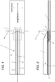
- a panel assembly shown in Figures 1-5 comprises a panel 1 carrying multiple stringers 2. Only one of the stringers is shown in Figure 1 , but three of the stringers are shown side-by-side in Figure 3 . All of the stringers are similar, so only the stringer 2 shown in Figure 1 will be described in detail.
- the stringer 2 has a T-shaped cross-section as shown in Figure 3 , with a stringer foot and an upstanding stringer web 4.
- the stringer web 4 upstands by a maximum height H from the stringer foot as shown in Figure 2 and 3 .
- a web run-out 8 At the end of the stringer web 4 there is a web run-out 8 which terminates at a tip 7.
- the web run-out 8 tapers so that the height of the web run-out 8 reduces towards the tip 7 as shown in Figure 2 .
- the stringer foot has two symmetrical halves: a flange 3a and foot run-out part 9a on one side of the web; and a flange 3b and foot run-out part 9b on the other side of the web.
- the majority of the stringer foot comprises the flanges 3a,b which each extend in a widthwise direction between the stringer web 4 and a respective lateral edge 5a,b.
- Each flange 3a,b also extends in a lengthwise direction alongside the stringer web 4 up to a respective foot run-out part 9a,b which coincides with the tapering web run-out 8.
- the foot run-out parts 9a,b each extend in the lengthwise direction between a respective flange 3a,b and a tip 6 of the stringer foot.
- the tip 6 of the stringer foot is a straight edge running in the widthwise direction perpendicular to the lengthwise direction, although other geometries may be possible.
- the first foot run-out part 9a extends in the widthwise direction between a first side 4a of the stringer web and a first lateral edge
- the second foot run-out part 9b extends in the widthwise direction between a second side 4b of the stringer web opposite the first side 4a of the stringer web and a second lateral edge.
- the tip 7 of the web and the tip 6 of the stringer foot all lie in the same tip plane 6a perpendicular to the lengthwise direction.
- Figure 1 shows only one end of the stringer 2.
- the opposite end of the stringer may be similar, or different to the end of the stringer shown in Figure 1 .
- the flanges 3a,b run along the full length of the stringer between the foot run-out parts 9a,b and the opposite end of the stringer.
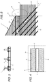
- the stringer foot 3a,3b,9a,9b is bonded to the panel at a stringer/panel interface (or bondline) which runs the full length of the stringer.
- the stringer/panel interface comprises a flange interface 10 where the flanges 3a,b are bonded to the panel, and a foot run-out interface 11 where the foot run-out parts 9a,b are bonded to the panel.
- the panel 1 and the stringer 2 are both made from fibre-reinforced composite materials. More specifically - the panel 1 comprises multiple plies of fibre-reinforced composite material, such as carbon fibres impregnated or infused with an epoxy resin matrix.
- the stringer 2 is typically made from a similar (or the same) composite material. That is, the stringer foot 3a,3b,9a,9b and the stringer web 4 are made from multiple plies of fibre-reinforced composite material, such as carbon fibres impregnated or infused with an epoxy resin matrix.
- the stringer foot is illustrated schematically in Figure 3 as separate from the stringer web 4, in a preferred embodiment the stringer 2 is constructed as two back-to-back L-section pieces - as shown in Fig 1 of US5827383 for example.
- Figure 5 is an enlarged view of the end of the stringer 2 and the panel 1, the horizontal shading indicating the planes of the plies of fibre-reinforced composite material.
- the panel assembly is manufactured by assembling dry fibre preforms (i.e. carbon fibre without any epoxy resin matrix) then injecting the preforms with epoxy resin matrix material to simultaneously infuse the panel 1 and the stringers 2. This infusion process fully wets the carbon fibre preforms, and the curing of the resin forms bonded joints between the individual plies, and a bonded joint between the stringer 2 and the panel 1 at the stringer/panel interface 10,11.
- each reinforcement element 12 passes through the full thickness of the stringer foot and the full thickness of the panel 1.
- each reinforcement element 12 is a tuft - that is, a loop of fibre such as carbon-fibre.
- the individual tufts 12 may be connected to adjacent tufts by seams, or more typically they are independent with no seams.
- the reinforcement elements 12 may be Z-pins made of carbon-fibre, steel, copper or any other suitable material. In the following description the reinforcement elements 12 will be referred to as tufts.
- Figure 6 is a schematic view of a tufting head 13 inserting the tufts 12. The tufts are inserted simultaneously, each tuft being inserted by a respective needle inclined at the necessary angle and direction of inclination. An imprint of the required tufting parameters (angle, pattern, density, and profile) is defined in the tufting head 13.
- the tufts 12 are inserted before the infusion process, so the infusion process fully wets the tufts, and the curing of the resin forms bonds between the tufts and the resin.
- the tufts 12 may be inserted after infusion, or the stringers and panel may be laid up as wet prepreg (resin-impregnated carbon fibre).
- the tufts 12 are distributed across the full extent of the foot run-out parts 9a,b and also across part of the flanges 3a,b. As shown in Figure 5 , the tufts pass through the foot run-out interface 11 from the foot run-out parts 9a,b into the panel 1. A small number of the tufts are also inserted into the flanges 3a,b - these tufts passing through the flange interface 10 between the flanges and the panel. The rest of each flange is free of tufts as shown in Figure 2 . In other examples, the tufts may only cover part of the foot run-out parts 9a,b.
- the tufts are distributed in first and second series 12a,b of rows which pass through the first 9a and second 9b foot run-out parts respectively.
- the first series 12a has twenty-one rows
- the second series 12b also has twenty-one rows.
- Each series 12a,b includes an end row nearest to the tip 6 of the stringer foot and twenty further rows spaced progressively further back from the tip of the stringer foot.
- the rows of the first series 12a extend laterally away from the first side 4a of the stringer web towards the first lateral edge
- the rows of the second series 12b extend laterally away from the second side 4b of the stringer web towards the second lateral edge.
- the end row of the first series 12a consists of six tufts which are distributed along a first polygonal curve 14a which is not a straight line
- the end row of the second series 12b consists of six tufts which are distributed along a second polygonal curve 14b which is also not a straight line.
- Polygonal curves 14a,b and 15a,b are indicated in Figure 7 for the end rows and one of the further rows, but not for the other rows. Note that the polygonal curves indicated in Figure 7 are constructed from imaginary straight line segments connecting the tufts. So the straight line segments shown in Figure 7 do not indicate seams between the tufts (although optionally there may be seams which follow these lines). Note that the corner of each foot run-out part 9a,b next to the tip 6 is free of tufts.
- each row consists of six tufts, but in other embodiments there may be more tufts (for instance sixteen per row) or fewer tufts (for instance three, four or five per row).
- the centre-to-centre pitch between the adjacent tufts in each row does not vary substantially along each row.
- the average centre-to-centre pitch (labelled P in Figure 7 ) along a row is 3.5mm and the diameter of each tuft is 0.5mm.
- the centre-to-centre pitch may vary slightly either side of the average along a row, but preferably by no more than 20% (0.7mm).
- the centre-to-centre pitch between rows is also approximately 3.5 mm.
- each row has the same number of tufts so the centre-to-centre pitch P does not vary from row-to-row.
- the number of tufts per row may increase from row-to-row away from the tip 6, so the centre-to-centre pitch P decreases from row-to-row.
- Each polygonal curve has a "C" shape with a convex side facing the tip 6 of the stringer foot and a concave side facing away from the tip 6 of the stringer foot.
- Each polygonal curve may have a portion where adjacent line segments are co-linear, that is, they lie in a straight line.
- the polygonal curve 14a includes two adjacent line segments which are co-linear. However, none of the polygonal curves are entirely straight.
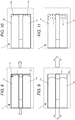
- FIGs 8-11 The distribution pattern for the tufts 12 is determined in a design phase shown in Figures 8-11.
- Figures 8 and 9 illustrate a failure test of a test specimen with the same structure as the panel assembly of Figure 1 , except with only a single stringer.
- the test specimen is stressed by applying a tensile force indicated by arrows, the size of the arrows in Figures 8 and 9 indicating the size of the force.
- the tensile force is applied by holding the panel and stringer at one end, and holding just the panel at the other end.
- the force is increased in a series of equal steps.
- Figure 8 shows the test specimen at the end of a first step, when a crack has formed at the tip 6 of the stringer foot and propagated along the length of the stringer 2 to the position indicated 15a.
- a small ultrasonic probe 18 is scanned across the back of the panel 1.
- An ultrasonic signal is transmitted through the test specimen and echo signals are received. Diminished strength of the echo signal at a particular location defines the presence of a crack (or start of the crack front).
- the crack locations are marked on the test specimen to obtain a first pair of rows of data points 16a,b shown in Figure 10 corresponding with the crack profile of Figure 8 .
- An approximate smooth curve over the data points is drawn to represent the crack front.
- the ultrasonic inspection device 18 is scanned again across the foot run-out parts 9a,b to obtain a second pair of rows of data points 17a,b shown in Figure 11 corresponding with the crack profile of Figure 9 .
- the process is repeated to obtain a full set of data points.
- tufts 12 are inserted through the foot run-out interface in the distribution pattern of Figure 7 , using the series of rows of data points from the design phase as a guide to determine the distribution pattern.
- a finite element analysis is performed on a computer model of the assembly (consisting of the stringer, panel, run-out and tufts) to theoretically predict the crack profile and number of tufts needed in each row to contain the crack growth.
- This analysis is performed by a suitably programmed computer to obtain the series of rows of data points 16a,b;17a,b each row corresponding with a respective theoretical crack profile.
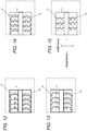
- each tuft 12 has a first (upper) portion 121 in the foot run-out 9a,b and a second (lower) portion 122 in the panel 1.
- the tufts are inclined in a direction of inclination which is away from the tip 6 of the stringer foot, so that the first portion 121 is further from the tip 6 of the stringer foot than the second portion 122.
- the direction of inclination of the tufts is also parallel with the lengthwise direction as shown in Figure 12 .
- Each arrow in Figure 12 indicates a tuft, with the arrow head showing the direction of inclination. So as shown in Figure 12 all of the tufts are inclined directly away from the tip 6 of the stringer foot in the lengthwise direction.
- Figure 13 shows an alternative embodiment in which the tufts are inclined in the opposite direction, towards the tip 6 of the stringer foot.
- Figure 14 shows a further alternative embodiment in which columns of tufts are inclined in alternating senses, towards and away from the tip 6 of the stringer foot.
- Figure 15 shows a further alternative embodiment in which the tufts are inclined towards the tip 6 of the stringer foot, but the direction of inclination is not parallel with the lengthwise direction but rather defines an angle of azimuth of +/- 45°.
- the arrows in Figure 15 could be reversed so that the tufts are inclined away from the tip 6 of the stringer foot.
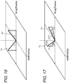
- Figures 16 and 17 illustrate the difference between the angle of inclination and the angle of azimuth for the tufts.
- Figure 16 shows a tuft 12a angled away from the stringer tip as in Figure 12 , and a tuft 12b angled towards the stringer tip as in Figure 13 .
- the orthogonal projection of the tuft onto the plane of the foot run-out interface 11 is parallel with the lengthwise direction, so the angle of azimuth relative to the lengthwise direction is zero.
- Figure 17 shows a first tuft 12c angled away from the stringer tip with an angle of inclination ⁇ 1, and a second tuft 12d angled towards the stringer tip with an angle of inclination ⁇ 2.
- the orthogonal projection of each tuft onto the plane of the foot run-out interface 11 is not parallel with the lengthwise direction. Rather the orthogonal projection of the first tuft 12c defines an angle of azimuth ⁇ 1 relative to the lengthwise direction, and the orthogonal projection of the second tuft 12d defines an angle of azimuth ⁇ 2 relative to the lengthwise direction.
- half of the tufts have an angle of azimuth ⁇ of +45°, and the other half of the tufts have an angle of azimuth ⁇ of -45°.
- the angle of azimuth is shown as precisely zero, but in practice manufacturing tolerances will mean that the angle of azimuth of each tuft may deviate from zero by up to 5°, 10° or 15°. However, as long as the angle of azimuth is sufficiently low then the inclined tufts will be sufficiently aligned with the lengthwise direction to provide advantages compared with vertical tufts.
- Deformation around the run-out is highly dependent on the geometrical features which lead to formation of the crack and the crack growth. Based on the geometry and the loads, peak tensile and shear stresses are developed at the tip of the run-out or at the crack front after formation of the crack.
- peak tensile and shear stresses are developed at the tip of the run-out or at the crack front after formation of the crack.
- the tufts When vertical tufts are placed behind the crack front (supposing the crack has formed and passed through the tufts) then the tufts reduce the through-thickness tensile stress at the crack tip. However, they do not significantly affect the transverse shear stress. Inclining the tufts behind the crack front considerably reduces the peak tensile and the shear stresses at the crack tip.
- Figure 18 is a view of a stringer 2 and panel 1 with no tufts, showing the deformation of the stringer and panel predicted by a finite element analysis (FEA) model after a crack has propagated between them. Note that there is a distinct upward kink at the tip of the stringer 2.
- Figure 19 shows the output of the same FEA model but with vertical tufts 123. Note that the kink is still present.
- Figure 20 shows the output of the same FEA model but with tufts 124 inclined away from the tip of the stringer. Note that there is no kink in the stringer run-out. This relative lack of deformation of the stringer run-out is beneficial because it reduces tensile and shear stresses at the crack front.
- FEA finite element analysis
- the inclined tufts modify the local load path as shown in Figure 5 - the arrows indicating the load path from the panel 1 to the stringer 2 via the inclined tufts.
- Calculations show that for a tufting density of 4%, the shear stiffness of the joint is doubled for tufts inclined at 45° in the region that is still bonded, which will alleviate the transverse shear stresses at the crack front or at the tip of the run-out before a crack is formed, thereby reducing the chance of a crack spreading by shear, or even forming in the first place.
- the first row of inclined tufts is sufficiently close to the tip 6 that they extend through the plane 6a of the tip as shown in Figure 5 .
- the first row of tufts is positioned as close as possible to the tip 6 of the stringer foot, in order to provide this reduced load flow in the local zone 20.
- the distance D between the first row of tufts and the tip 6 of the foot run-out, at the point where the tuft passes through the interface 11, is less than the thickness of the panel 1 at the interface 11.
- the thickness of the panel 1 at the interface 11 could vary - for example it might be between 3mm and 10mm.
- the distance D is greater than 3.5mm but less than 10mm.
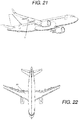
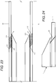
- Figures 21 and 22 show an aircraft with a pair of wings. Each wing has an upper (low pressure) skin 30 and a lower (high pressure) skin 31.
- Figure 23 is a schematic sectional view through one of the aircraft wings showing only the upper and lower skins 30, 31. Each skin comprises a panel assembly as shown in Figures 1-5 , so it will not be described again in detail.
- the wing is attached to the fuselage at its root, and extends in a spanwise direction to its tip.
- the stringers extend in the spanwise direction from an inboard end at the root of the wing to an outboard end towards the tip of the wing.
- Figure 23 shows only the outboard end of the stringer 2.
- the inboard end of the stringer typically has a different construction, running into the wing root joint and being held down by cleats for example.
- the aerodynamic loads acting on the wing cause it to bend upwards so the lower skin is in tension. Therefore in the lower skin 31 the tufts are inclined in a direction of inclination which is away from the tip of the stringer foot. So the first (upper) portion 121 of each tuft in the stringer foot is further from the tip 6 of the stringer foot than the second (lower) portion 122 of the tuft in the lower skin 31.
- the upward bending of the wing causes the upper skin 30 to be in compression, so the direction of inclination of the tufts is reversed compared with the lower skin. So in the upper skin the tufts are inclined in a direction of inclination which is towards the tip 6 of the stringer foot, so that the first (lower) portion 121 of each tuft in the stringer foot is closer to the tip 6 of the stringer foot than the second (upper) portion 122 of the tuft in the upper skin 30.
Landscapes
- Engineering & Computer Science (AREA)
- Mechanical Engineering (AREA)
- Aviation & Aerospace Engineering (AREA)
- Chemical & Material Sciences (AREA)
- Composite Materials (AREA)
- Moulding By Coating Moulds (AREA)
- Working Measures On Existing Buildindgs (AREA)
Claims (15)
- Ensemble panneau pour une peau composite d'une aile d'aéronef, l'ensemble panneau comprenant :un panneau (1),une lisse (2) comprenant un pied de lisse et un plat de lisse vertical (4), le pied de lisse comprenant une bride (3a, 3b) qui s'étend dans le sens de la largeur, entre le plat de lisse (4) et un bord latéral (5a, 5b) et dans le sens de la longueur, le long du plat de lisse (4), la lisse s'étendant dans le sens de la longueur, entre une paire de extrémités et une des extrémités de la lisse comprenant une partie terminale (9a, 9b) qui s'étend dans le sens de la longueur, entre la bride (3a, 3b) et une pointe (6) du pied de lisse, la partie terminale (9a, 9b) étant liée au panneau (1), au niveau d'une interface de partie terminale du pied de lisse (11) etdes éléments de renforcement (12) qui passent à travers l'interface de la partie terminale du pied de lisse (11),les éléments de renforcement (12) étant répartis à travers l'interface de la partie terminale du pied de lisse (11) en une série de rangées incluant une dernière rangée la plus proche de la pointe du pied de lisse et d'autres rangées progressivement espacées de la pointe du pied de lisse dans le sens de la longueur, et au moins la dernière rangée comprenant trois éléments de renforcement (12) ou plus qui sont répartis le long d'une courbe polygonale qui n'est pas une ligne droite.
- Ensemble panneau suivant la revendication 1, dans lequel les éléments de renforcement (12) sont liés à la partie terminale du pied de lisse (9a, 9b) et/ou au panneau.
- Ensemble panneau suivant une des revendications précédentes, dans lequel au moins la dernière rangée comprend quatre, cinq, six éléments de renforcement (12) ou plus qui sont répartis le long de la courbe polygonale.
- Ensemble panneau suivant une des revendications précédentes, dans lequel au moins quelques-unes des autres rangées comprennent trois éléments de renforcement (12) ou plus qui sont répartis le long d'une courbe polygonale respective.
- Ensemble panneau suivant une des revendications précédentes, dans lequel au moins quelques-unes des autres rangées comprennent quatre, cinq, six éléments de renforcement (12) ou plus qui sont répartis le long d'une courbe polygonale respective.
- Ensemble panneau suivant une des revendications précédentes, dans lequel les séries de rangées ne forment pas une grille rectiligne ou une grille de polygones identiques.
- Ensemble panneau suivant une des revendications précédentes, dans lequel les éléments de renforcement (12) de la dernière rangée sont espacés le long de la courbe polygonale d'un pas de centre à centre qui est sensiblement constant ou ne présente pas de variation supérieure à 10% ou 20% d'un pas de centre à centre moyen de la dernière rangée.
- Ensemble panneau suivant une des revendications précédentes, dans lequel la courbe polygonale ou chaque courbe polygonale respective possède un côté convexe faisant face à la pointe (6) du pied de lisse et un côté concave opposé à la pointe (6) du pied de lisse.
- Ensemble panneau suivant une des revendications précédentes, dans lequel chaque élément de renforcement (12) possède un diamètre inférieur à 2mm.
- Ensemble panneau suivant une des revendications précédentes, dans lequel la partie terminale du pied de lisse (9a, 9b) comprend plusieurs couches et les éléments de renforcement (12) passent à travers quelques-unes ou toutes les couches de la partie terminale du pied de lisse (9a, 9b).
- Ensemble panneau suivant une des revendications précédentes, dans lequel le panneau (1) comprend plusieurs couches et les éléments de renforcement (12) passent à travers quelques-unes ou toutes les couches du panneau.
- Ensemble panneau suivant une des revendications précédentes, dans lequel le panneau (1) présente une épaisseur au niveau de l'interface de la partie terminale du pied de lisse (11) et au moins quelques-uns des éléments de renforcement (12) sont espacés de la pointe (6) du pied de lisse à l'endroit où ils passent à travers l'interface de la partie terminale du pied de lisse (11), d'une distance inférieure à l'épaisseur du panneau (1) au niveau de l'interface de la partie terminale du pied de lisse (11).
- Ensemble panneau suivant une des revendications précédentes, dans lequel la partie terminale du pied de lisse (9a, 9b) comprend une première bride de la partie terminale du pied de lisse (9a) qui s'étend dans le sens de la largeur entre un premier côté du plat de lisse et un premier bord latéral (5a) et une seconde bride de la partie terminale du pied de lisse (9b) qui s'étend dans le sens de la largeur entre un second côté du plat de lisse opposé au premier côté du plat de lisse et un second bord latéral (5b), les éléments de renforcement (12) étant répartis en une première et une seconde série de rangées qui passent respectivement à travers la première et la seconde bride de la partie terminale du pied de lisse (9a, 9b), chaque rangée incluant une dernière rangée la plus proche de la pointe (6) du pied de lisse et d'autres rangées espacées progressivement de la pointe (6) du pied de lisse, les rangées de la première série s'étendant latéralement de sorte à s'éloigner du premier côté du plat de lisse en direction du premier bord latéral (5a), les rangées de la seconde série s'étendant latéralement de sorte à s'éloigner du second côté du plat de lisse envers le second bord latéral (5b), la dernière rangée de la première série comprenant trois éléments de renforcement (12) ou plus qui sont répartis le long d'une première courbe polygonale et la dernière rangée de la seconde série comprenant trois éléments de renforcement (12) ou plus qui sont répartis le long d'une seconde courbe polygonale.
- Aéronef comprenant un ensemble panneau suivant une des revendications précédentes.
- Procédé de renforcement d'un ensemble panneau pour une peau composite d'une aile d'aéronef, l'ensemble panneau comprenant: un panneau (1), une lisse (2) comprenant un pied de lisse et un plat de lisse vertical (4), le pied de lisse comprenant une bride (3a, 3b) qui s'étend dans le sens de la largeur, entre le plat de lisse (4) et un bord latéral (5a, 5b), et dans le sens de la longueur, le long du plat de lisse (4), la lisse s'étendant dans le sens de la longueur entre une paire d'extrémités et une des extrémités de la lisse comprenant une partie terminale (9a, 9b) qui s'étend entre la bride (3a, 3b) et une pointe (6) du pied de lisse, la partie terminale du pied de lisse (9a, 9b) entrant en contact avec le panneau (1) au niveau d'une interface de la partie terminale du pied de lisse (11), le procédé comprenant :au cours d'une phase de conception, la réalisation d'un essai de défaillance d'un échantillon d'essai ou d'une analyse de défaillance d'un modèle informatique pour obtenir une série de rangées de points correspondant chacune à un profil respectif de fissure, etau cours d'une phase de renforcement, l'insertion d'éléments de renforcement (12) à travers l'interface de la partie terminale du pied de lisse (11) selon un motif de répartition et l'utilisation de la série de rangées de points de la phase de conception pour déterminer le motif de répartition des éléments de renforcement (12) à travers l'interface de la partie terminale du pied de lisse (11).
Applications Claiming Priority (1)
| Application Number | Priority Date | Filing Date | Title |
|---|---|---|---|
| GB1712913.1A GB2565350A (en) | 2017-08-11 | 2017-08-11 | Panel assembly |
Publications (2)
| Publication Number | Publication Date |
|---|---|
| EP3441299A1 EP3441299A1 (fr) | 2019-02-13 |
| EP3441299B1 true EP3441299B1 (fr) | 2021-05-05 |
Family
ID=59895875
Family Applications (1)
| Application Number | Title | Priority Date | Filing Date |
|---|---|---|---|
| EP18186317.6A Active EP3441299B1 (fr) | 2017-08-11 | 2018-07-30 | Ensemble de panneau |
Country Status (4)
| Country | Link |
|---|---|
| US (1) | US11124284B2 (fr) |
| EP (1) | EP3441299B1 (fr) |
| CN (1) | CN109383751A (fr) |
| GB (1) | GB2565350A (fr) |
Family Cites Families (22)
| Publication number | Priority date | Publication date | Assignee | Title |
|---|---|---|---|---|
| US3837985A (en) * | 1972-02-24 | 1974-09-24 | Whittaker Corp | Multi-directional reinforced composite and method of making the same |
| US4109435A (en) * | 1977-08-26 | 1978-08-29 | Rockwell International Corporation | Composite structural joint and method of fabrication thereof |
| US4350728A (en) * | 1980-10-02 | 1982-09-21 | The United States Of America As Represented By The Secretary Of The Navy | Cross reinforcement in a graphite-epoxy laminate |
| US5466506A (en) * | 1992-10-27 | 1995-11-14 | Foster-Miller, Inc. | Translaminar reinforcement system for Z-direction reinforcement of a fiber matrix structure |
| US5789061A (en) | 1996-02-13 | 1998-08-04 | Foster-Miller, Inc. | Stiffener reinforced assembly and method of manufacturing same |
| US5876540A (en) * | 1996-05-31 | 1999-03-02 | The Boeing Company | Joining composites using Z-pinned precured strips |
| DE10159067A1 (de) | 2001-12-01 | 2003-06-26 | Daimler Chrysler Ag | Faserverbund-Crashstruktur |
| FR2866626B1 (fr) * | 2004-02-20 | 2006-05-19 | Airbus France | Arret de raidisseur a pentes decalees et panneau muni d'un tel arret |
| DK176564B1 (da) * | 2004-12-29 | 2008-09-01 | Lm Glasfiber As | Fiberforstærket samling |
| GB0708333D0 (en) | 2007-04-30 | 2007-06-06 | Airbus Uk Ltd | Composite structure |
| GB0819159D0 (en) * | 2008-10-20 | 2008-11-26 | Airbus Uk Ltd | Joint between aircraft components |
| GB201005308D0 (en) * | 2010-03-30 | 2010-05-12 | Airbus Operations Ltd | Composite structural member |
| GB201016279D0 (en) * | 2010-09-28 | 2010-11-10 | Airbus Operations Ltd | Stiffener run-out |
| ES2398985B1 (es) * | 2011-03-14 | 2014-02-14 | Airbus Operations S.L. | Dispositivos de transferencia de carga en la terminación de un larguerillo. |
| KR101394408B1 (ko) * | 2011-10-07 | 2014-05-14 | 한국항공우주연구원 | Z-피닝 패치 및 이를 이용한 복합재 적층 구조물의 제조 또는 결합 방법 |
| ES2405155B1 (es) * | 2011-10-24 | 2014-09-02 | Airbus Operations S.L. | Zonas de terminación de larguerillos optimizadas en componentes de aeronaves |
| US8974886B2 (en) * | 2012-04-25 | 2015-03-10 | The Boeing Company | Disbond resistant composite stiffener runout |
| GB201209437D0 (en) * | 2012-05-28 | 2012-07-11 | Kitchener Renato | Power supply and battery charger |
| EP2909008B1 (fr) * | 2012-10-22 | 2018-04-11 | Saab Ab | Fixation intégrée de montant en plastique renforcé de fibres à un revêtement en plastique renforcé de fibres pour ailes portantes d'avion |
| EP2808156B1 (fr) | 2013-05-28 | 2017-07-12 | Airbus Operations GmbH | Segment d'enveloppe d'un aéronef et procédé de production |
| EP2808147B1 (fr) * | 2013-05-30 | 2017-03-01 | Airbus Operations S.L. | Outil hybride pour le durcissement de pièces de matériau composite |
| US9399509B2 (en) * | 2014-04-10 | 2016-07-26 | The Boeing Company | Vent stringer fitting |
-
2017
- 2017-08-11 GB GB1712913.1A patent/GB2565350A/en not_active Withdrawn
-
2018
- 2018-07-30 EP EP18186317.6A patent/EP3441299B1/fr active Active
- 2018-08-09 US US16/059,822 patent/US11124284B2/en active Active
- 2018-08-09 CN CN201810902801.5A patent/CN109383751A/zh active Pending
Also Published As
| Publication number | Publication date |
|---|---|
| EP3441299A1 (fr) | 2019-02-13 |
| GB201712913D0 (en) | 2017-09-27 |
| US20190047679A1 (en) | 2019-02-14 |
| CN109383751A (zh) | 2019-02-26 |
| US11124284B2 (en) | 2021-09-21 |
| GB2565350A (en) | 2019-02-13 |
Similar Documents
| Publication | Publication Date | Title |
|---|---|---|
| EP2822852B1 (fr) | Joint de recouvrement collé | |
| Mouritz | Review of z-pinned composite laminates | |
| US9371127B2 (en) | Composite structure comprising a stringer with a pad embedded in the recess of a panel and method of transmitting forces | |
| EP2441571B1 (fr) | Procédé pour la fabrication d'un composant composite en fibres | |
| EP3441303B1 (fr) | Ensemble de panneau | |
| CN107757873B (zh) | 用于在结构上支撑飞机机翼的系统和方法 | |
| EP2730498A2 (fr) | Joint pour ailes composites | |
| WO2012161741A2 (fr) | Semelles de longeron pour pale d'éolienne | |
| EP2808156B1 (fr) | Segment d'enveloppe d'un aéronef et procédé de production | |
| US20230415448A1 (en) | Honeycomb core sandwich panels | |
| US10618631B2 (en) | Reinforced blade and spar | |
| CN104448877B (zh) | 包括分散的纤维丝的复合织物 | |
| GB2245862A (en) | Manufacture of a composite material | |
| EP3441299B1 (fr) | Ensemble de panneau | |
| Ucsnik et al. | Composite to composite joint with lightweight metal reinforcement for enhanced damage tolerance | |
| EP4048509B1 (fr) | Améliorations se rapportant à la fabrication de pales d'éolienne | |
| EP2848518B1 (fr) | Poutre de charge en polymères renforcés de fibres de carbone avec plaque jointive en C et étançons de chargement intégrés | |
| US11685503B2 (en) | Stringer assemblies and methods of forming thereof |
Legal Events
| Date | Code | Title | Description |
|---|---|---|---|
| PUAI | Public reference made under article 153(3) epc to a published international application that has entered the european phase |
Free format text: ORIGINAL CODE: 0009012 |
|
| STAA | Information on the status of an ep patent application or granted ep patent |
Free format text: STATUS: THE APPLICATION HAS BEEN PUBLISHED |
|
| AK | Designated contracting states |
Kind code of ref document: A1 Designated state(s): AL AT BE BG CH CY CZ DE DK EE ES FI FR GB GR HR HU IE IS IT LI LT LU LV MC MK MT NL NO PL PT RO RS SE SI SK SM TR |
|
| AX | Request for extension of the european patent |
Extension state: BA ME |
|
| STAA | Information on the status of an ep patent application or granted ep patent |
Free format text: STATUS: REQUEST FOR EXAMINATION WAS MADE |
|
| 17P | Request for examination filed |
Effective date: 20190726 |
|
| RBV | Designated contracting states (corrected) |
Designated state(s): AL AT BE BG CH CY CZ DE DK EE ES FI FR GB GR HR HU IE IS IT LI LT LU LV MC MK MT NL NO PL PT RO RS SE SI SK SM TR |
|
| STAA | Information on the status of an ep patent application or granted ep patent |
Free format text: STATUS: EXAMINATION IS IN PROGRESS |
|
| 17Q | First examination report despatched |
Effective date: 20200320 |
|
| GRAP | Despatch of communication of intention to grant a patent |
Free format text: ORIGINAL CODE: EPIDOSNIGR1 |
|
| STAA | Information on the status of an ep patent application or granted ep patent |
Free format text: STATUS: GRANT OF PATENT IS INTENDED |
|
| INTG | Intention to grant announced |
Effective date: 20201127 |
|
| GRAS | Grant fee paid |
Free format text: ORIGINAL CODE: EPIDOSNIGR3 |
|
| GRAA | (expected) grant |
Free format text: ORIGINAL CODE: 0009210 |
|
| STAA | Information on the status of an ep patent application or granted ep patent |
Free format text: STATUS: THE PATENT HAS BEEN GRANTED |
|
| AK | Designated contracting states |
Kind code of ref document: B1 Designated state(s): AL AT BE BG CH CY CZ DE DK EE ES FI FR GB GR HR HU IE IS IT LI LT LU LV MC MK MT NL NO PL PT RO RS SE SI SK SM TR |
|
| REG | Reference to a national code |
Ref country code: GB Ref legal event code: FG4D |
|
| REG | Reference to a national code |
Ref country code: CH Ref legal event code: EP |
|
| REG | Reference to a national code |
Ref country code: AT Ref legal event code: REF Ref document number: 1389503 Country of ref document: AT Kind code of ref document: T Effective date: 20210515 |
|
| REG | Reference to a national code |
Ref country code: IE Ref legal event code: FG4D |
|
| REG | Reference to a national code |
Ref country code: DE Ref legal event code: R096 Ref document number: 602018016513 Country of ref document: DE |
|
| REG | Reference to a national code |
Ref country code: LT Ref legal event code: MG9D |
|
| REG | Reference to a national code |
Ref country code: AT Ref legal event code: MK05 Ref document number: 1389503 Country of ref document: AT Kind code of ref document: T Effective date: 20210505 |
|
| PG25 | Lapsed in a contracting state [announced via postgrant information from national office to epo] |
Ref country code: FI Free format text: LAPSE BECAUSE OF FAILURE TO SUBMIT A TRANSLATION OF THE DESCRIPTION OR TO PAY THE FEE WITHIN THE PRESCRIBED TIME-LIMIT Effective date: 20210505 Ref country code: HR Free format text: LAPSE BECAUSE OF FAILURE TO SUBMIT A TRANSLATION OF THE DESCRIPTION OR TO PAY THE FEE WITHIN THE PRESCRIBED TIME-LIMIT Effective date: 20210505 Ref country code: LT Free format text: LAPSE BECAUSE OF FAILURE TO SUBMIT A TRANSLATION OF THE DESCRIPTION OR TO PAY THE FEE WITHIN THE PRESCRIBED TIME-LIMIT Effective date: 20210505 Ref country code: AT Free format text: LAPSE BECAUSE OF FAILURE TO SUBMIT A TRANSLATION OF THE DESCRIPTION OR TO PAY THE FEE WITHIN THE PRESCRIBED TIME-LIMIT Effective date: 20210505 Ref country code: BG Free format text: LAPSE BECAUSE OF FAILURE TO SUBMIT A TRANSLATION OF THE DESCRIPTION OR TO PAY THE FEE WITHIN THE PRESCRIBED TIME-LIMIT Effective date: 20210805 |
|
| PG25 | Lapsed in a contracting state [announced via postgrant information from national office to epo] |
Ref country code: LV Free format text: LAPSE BECAUSE OF FAILURE TO SUBMIT A TRANSLATION OF THE DESCRIPTION OR TO PAY THE FEE WITHIN THE PRESCRIBED TIME-LIMIT Effective date: 20210505 Ref country code: PL Free format text: LAPSE BECAUSE OF FAILURE TO SUBMIT A TRANSLATION OF THE DESCRIPTION OR TO PAY THE FEE WITHIN THE PRESCRIBED TIME-LIMIT Effective date: 20210505 Ref country code: PT Free format text: LAPSE BECAUSE OF FAILURE TO SUBMIT A TRANSLATION OF THE DESCRIPTION OR TO PAY THE FEE WITHIN THE PRESCRIBED TIME-LIMIT Effective date: 20210906 Ref country code: NO Free format text: LAPSE BECAUSE OF FAILURE TO SUBMIT A TRANSLATION OF THE DESCRIPTION OR TO PAY THE FEE WITHIN THE PRESCRIBED TIME-LIMIT Effective date: 20210805 Ref country code: RS Free format text: LAPSE BECAUSE OF FAILURE TO SUBMIT A TRANSLATION OF THE DESCRIPTION OR TO PAY THE FEE WITHIN THE PRESCRIBED TIME-LIMIT Effective date: 20210505 Ref country code: SE Free format text: LAPSE BECAUSE OF FAILURE TO SUBMIT A TRANSLATION OF THE DESCRIPTION OR TO PAY THE FEE WITHIN THE PRESCRIBED TIME-LIMIT Effective date: 20210505 Ref country code: IS Free format text: LAPSE BECAUSE OF FAILURE TO SUBMIT A TRANSLATION OF THE DESCRIPTION OR TO PAY THE FEE WITHIN THE PRESCRIBED TIME-LIMIT Effective date: 20210905 Ref country code: GR Free format text: LAPSE BECAUSE OF FAILURE TO SUBMIT A TRANSLATION OF THE DESCRIPTION OR TO PAY THE FEE WITHIN THE PRESCRIBED TIME-LIMIT Effective date: 20210806 |
|
| REG | Reference to a national code |
Ref country code: NL Ref legal event code: MP Effective date: 20210505 |
|
| PG25 | Lapsed in a contracting state [announced via postgrant information from national office to epo] |
Ref country code: NL Free format text: LAPSE BECAUSE OF FAILURE TO SUBMIT A TRANSLATION OF THE DESCRIPTION OR TO PAY THE FEE WITHIN THE PRESCRIBED TIME-LIMIT Effective date: 20210505 |
|
| PG25 | Lapsed in a contracting state [announced via postgrant information from national office to epo] |
Ref country code: DK Free format text: LAPSE BECAUSE OF FAILURE TO SUBMIT A TRANSLATION OF THE DESCRIPTION OR TO PAY THE FEE WITHIN THE PRESCRIBED TIME-LIMIT Effective date: 20210505 Ref country code: CZ Free format text: LAPSE BECAUSE OF FAILURE TO SUBMIT A TRANSLATION OF THE DESCRIPTION OR TO PAY THE FEE WITHIN THE PRESCRIBED TIME-LIMIT Effective date: 20210505 Ref country code: RO Free format text: LAPSE BECAUSE OF FAILURE TO SUBMIT A TRANSLATION OF THE DESCRIPTION OR TO PAY THE FEE WITHIN THE PRESCRIBED TIME-LIMIT Effective date: 20210505 Ref country code: SM Free format text: LAPSE BECAUSE OF FAILURE TO SUBMIT A TRANSLATION OF THE DESCRIPTION OR TO PAY THE FEE WITHIN THE PRESCRIBED TIME-LIMIT Effective date: 20210505 Ref country code: SK Free format text: LAPSE BECAUSE OF FAILURE TO SUBMIT A TRANSLATION OF THE DESCRIPTION OR TO PAY THE FEE WITHIN THE PRESCRIBED TIME-LIMIT Effective date: 20210505 Ref country code: EE Free format text: LAPSE BECAUSE OF FAILURE TO SUBMIT A TRANSLATION OF THE DESCRIPTION OR TO PAY THE FEE WITHIN THE PRESCRIBED TIME-LIMIT Effective date: 20210505 Ref country code: ES Free format text: LAPSE BECAUSE OF FAILURE TO SUBMIT A TRANSLATION OF THE DESCRIPTION OR TO PAY THE FEE WITHIN THE PRESCRIBED TIME-LIMIT Effective date: 20210505 |
|
| REG | Reference to a national code |
Ref country code: DE Ref legal event code: R097 Ref document number: 602018016513 Country of ref document: DE |
|
| REG | Reference to a national code |
Ref country code: CH Ref legal event code: PL |
|
| PLBE | No opposition filed within time limit |
Free format text: ORIGINAL CODE: 0009261 |
|
| STAA | Information on the status of an ep patent application or granted ep patent |
Free format text: STATUS: NO OPPOSITION FILED WITHIN TIME LIMIT |
|
| PG25 | Lapsed in a contracting state [announced via postgrant information from national office to epo] |
Ref country code: MC Free format text: LAPSE BECAUSE OF FAILURE TO SUBMIT A TRANSLATION OF THE DESCRIPTION OR TO PAY THE FEE WITHIN THE PRESCRIBED TIME-LIMIT Effective date: 20210505 |
|
| REG | Reference to a national code |
Ref country code: BE Ref legal event code: MM Effective date: 20210731 |
|
| 26N | No opposition filed |
Effective date: 20220208 |
|
| PG25 | Lapsed in a contracting state [announced via postgrant information from national office to epo] |
Ref country code: LI Free format text: LAPSE BECAUSE OF NON-PAYMENT OF DUE FEES Effective date: 20210731 Ref country code: CH Free format text: LAPSE BECAUSE OF NON-PAYMENT OF DUE FEES Effective date: 20210731 |
|
| PG25 | Lapsed in a contracting state [announced via postgrant information from national office to epo] |
Ref country code: IS Free format text: LAPSE BECAUSE OF FAILURE TO SUBMIT A TRANSLATION OF THE DESCRIPTION OR TO PAY THE FEE WITHIN THE PRESCRIBED TIME-LIMIT Effective date: 20210905 Ref country code: LU Free format text: LAPSE BECAUSE OF NON-PAYMENT OF DUE FEES Effective date: 20210730 Ref country code: AL Free format text: LAPSE BECAUSE OF FAILURE TO SUBMIT A TRANSLATION OF THE DESCRIPTION OR TO PAY THE FEE WITHIN THE PRESCRIBED TIME-LIMIT Effective date: 20210505 |
|
| PG25 | Lapsed in a contracting state [announced via postgrant information from national office to epo] |
Ref country code: IT Free format text: LAPSE BECAUSE OF FAILURE TO SUBMIT A TRANSLATION OF THE DESCRIPTION OR TO PAY THE FEE WITHIN THE PRESCRIBED TIME-LIMIT Effective date: 20210505 Ref country code: IE Free format text: LAPSE BECAUSE OF NON-PAYMENT OF DUE FEES Effective date: 20210730 Ref country code: BE Free format text: LAPSE BECAUSE OF NON-PAYMENT OF DUE FEES Effective date: 20210731 |
|
| PG25 | Lapsed in a contracting state [announced via postgrant information from national office to epo] |
Ref country code: CY Free format text: LAPSE BECAUSE OF FAILURE TO SUBMIT A TRANSLATION OF THE DESCRIPTION OR TO PAY THE FEE WITHIN THE PRESCRIBED TIME-LIMIT Effective date: 20210505 |
|
| PG25 | Lapsed in a contracting state [announced via postgrant information from national office to epo] |
Ref country code: HU Free format text: LAPSE BECAUSE OF FAILURE TO SUBMIT A TRANSLATION OF THE DESCRIPTION OR TO PAY THE FEE WITHIN THE PRESCRIBED TIME-LIMIT; INVALID AB INITIO Effective date: 20180730 |
|
| PG25 | Lapsed in a contracting state [announced via postgrant information from national office to epo] |
Ref country code: MK Free format text: LAPSE BECAUSE OF FAILURE TO SUBMIT A TRANSLATION OF THE DESCRIPTION OR TO PAY THE FEE WITHIN THE PRESCRIBED TIME-LIMIT Effective date: 20210505 |
|
| PG25 | Lapsed in a contracting state [announced via postgrant information from national office to epo] |
Ref country code: TR Free format text: LAPSE BECAUSE OF FAILURE TO SUBMIT A TRANSLATION OF THE DESCRIPTION OR TO PAY THE FEE WITHIN THE PRESCRIBED TIME-LIMIT Effective date: 20210505 |
|
| PG25 | Lapsed in a contracting state [announced via postgrant information from national office to epo] |
Ref country code: MT Free format text: LAPSE BECAUSE OF FAILURE TO SUBMIT A TRANSLATION OF THE DESCRIPTION OR TO PAY THE FEE WITHIN THE PRESCRIBED TIME-LIMIT Effective date: 20210505 |
|
| PGFP | Annual fee paid to national office [announced via postgrant information from national office to epo] |
Ref country code: DE Payment date: 20250722 Year of fee payment: 8 |
|
| PGFP | Annual fee paid to national office [announced via postgrant information from national office to epo] |
Ref country code: GB Payment date: 20250722 Year of fee payment: 8 |
|
| PGFP | Annual fee paid to national office [announced via postgrant information from national office to epo] |
Ref country code: FR Payment date: 20250725 Year of fee payment: 8 |