EP3441285B1 - Electric power steering device - Google Patents
Electric power steering device Download PDFInfo
- Publication number
- EP3441285B1 EP3441285B1 EP16897884.9A EP16897884A EP3441285B1 EP 3441285 B1 EP3441285 B1 EP 3441285B1 EP 16897884 A EP16897884 A EP 16897884A EP 3441285 B1 EP3441285 B1 EP 3441285B1
- Authority
- EP
- European Patent Office
- Prior art keywords
- housing
- control unit
- phase
- winding
- electric
- Prior art date
- Legal status (The legal status is an assumption and is not a legal conclusion. Google has not performed a legal analysis and makes no representation as to the accuracy of the status listed.)
- Active
Links
Images

Classifications
-
- B—PERFORMING OPERATIONS; TRANSPORTING
- B62—LAND VEHICLES FOR TRAVELLING OTHERWISE THAN ON RAILS
- B62D—MOTOR VEHICLES; TRAILERS
- B62D5/00—Power-assisted or power-driven steering
- B62D5/04—Power-assisted or power-driven steering electrical, e.g. using an electric servo-motor connected to, or forming part of, the steering gear
- B62D5/0403—Power-assisted or power-driven steering electrical, e.g. using an electric servo-motor connected to, or forming part of, the steering gear characterised by constructional features, e.g. common housing for motor and gear box
- B62D5/0406—Power-assisted or power-driven steering electrical, e.g. using an electric servo-motor connected to, or forming part of, the steering gear characterised by constructional features, e.g. common housing for motor and gear box including housing for electronic control unit
-
- H—ELECTRICITY
- H02—GENERATION; CONVERSION OR DISTRIBUTION OF ELECTRIC POWER
- H02K—DYNAMO-ELECTRIC MACHINES
- H02K11/00—Structural association of dynamo-electric machines with electric components or with devices for shielding, monitoring or protection
- H02K11/30—Structural association with control circuits or drive circuits
- H02K11/33—Drive circuits, e.g. power electronics
-
- H—ELECTRICITY
- H02—GENERATION; CONVERSION OR DISTRIBUTION OF ELECTRIC POWER
- H02K—DYNAMO-ELECTRIC MACHINES
- H02K3/00—Details of windings
- H02K3/46—Fastening of windings on the stator or rotor structure
- H02K3/50—Fastening of winding heads, equalising connectors, or connections thereto
-
- H—ELECTRICITY
- H02—GENERATION; CONVERSION OR DISTRIBUTION OF ELECTRIC POWER
- H02K—DYNAMO-ELECTRIC MACHINES
- H02K5/00—Casings; Enclosures; Supports
- H02K5/04—Casings or enclosures characterised by the shape, form or construction thereof
-
- H—ELECTRICITY
- H02—GENERATION; CONVERSION OR DISTRIBUTION OF ELECTRIC POWER
- H02K—DYNAMO-ELECTRIC MACHINES
- H02K5/00—Casings; Enclosures; Supports
- H02K5/04—Casings or enclosures characterised by the shape, form or construction thereof
- H02K5/22—Auxiliary parts of casings not covered by groups H02K5/06-H02K5/20, e.g. shaped to form connection boxes or terminal boxes
- H02K5/225—Terminal boxes or connection arrangements
-
- B—PERFORMING OPERATIONS; TRANSPORTING
- B62—LAND VEHICLES FOR TRAVELLING OTHERWISE THAN ON RAILS
- B62D—MOTOR VEHICLES; TRAILERS
- B62D5/00—Power-assisted or power-driven steering
- B62D5/04—Power-assisted or power-driven steering electrical, e.g. using an electric servo-motor connected to, or forming part of, the steering gear
- B62D5/0457—Power-assisted or power-driven steering electrical, e.g. using an electric servo-motor connected to, or forming part of, the steering gear characterised by control features of the drive means as such
- B62D5/046—Controlling the motor
- B62D5/0463—Controlling the motor calculating assisting torque from the motor based on driver input
-
- H—ELECTRICITY
- H02—GENERATION; CONVERSION OR DISTRIBUTION OF ELECTRIC POWER
- H02K—DYNAMO-ELECTRIC MACHINES
- H02K11/00—Structural association of dynamo-electric machines with electric components or with devices for shielding, monitoring or protection
- H02K11/20—Structural association of dynamo-electric machines with electric components or with devices for shielding, monitoring or protection for measuring, monitoring, testing, protecting or switching
- H02K11/21—Devices for sensing speed or position, or actuated thereby
-
- H—ELECTRICITY
- H02—GENERATION; CONVERSION OR DISTRIBUTION OF ELECTRIC POWER
- H02K—DYNAMO-ELECTRIC MACHINES
- H02K11/00—Structural association of dynamo-electric machines with electric components or with devices for shielding, monitoring or protection
- H02K11/20—Structural association of dynamo-electric machines with electric components or with devices for shielding, monitoring or protection for measuring, monitoring, testing, protecting or switching
- H02K11/24—Devices for sensing torque, or actuated thereby
-
- H—ELECTRICITY
- H02—GENERATION; CONVERSION OR DISTRIBUTION OF ELECTRIC POWER
- H02P—CONTROL OR REGULATION OF ELECTRIC MOTORS, ELECTRIC GENERATORS OR DYNAMO-ELECTRIC CONVERTERS; CONTROLLING TRANSFORMERS, REACTORS OR CHOKE COILS
- H02P25/00—Arrangements or methods for the control of AC motors characterised by the kind of AC motor or by structural details
- H02P25/16—Arrangements or methods for the control of AC motors characterised by the kind of AC motor or by structural details characterised by the circuit arrangement or by the kind of wiring
- H02P25/22—Multiple windings; Windings for more than three phases
-
- H—ELECTRICITY
- H02—GENERATION; CONVERSION OR DISTRIBUTION OF ELECTRIC POWER
- H02P—CONTROL OR REGULATION OF ELECTRIC MOTORS, ELECTRIC GENERATORS OR DYNAMO-ELECTRIC CONVERTERS; CONTROLLING TRANSFORMERS, REACTORS OR CHOKE COILS
- H02P27/00—Arrangements or methods for the control of AC motors characterised by the kind of supply voltage
- H02P27/04—Arrangements or methods for the control of AC motors characterised by the kind of supply voltage using variable-frequency supply voltage, e.g. inverter or converter supply voltage
- H02P27/06—Arrangements or methods for the control of AC motors characterised by the kind of supply voltage using variable-frequency supply voltage, e.g. inverter or converter supply voltage using DC to AC converters or inverters
Definitions
- the present invention relates to a vehicle electric power steering apparatus, particularly to an electric power steering apparatus in which a motor and a control unit are integrated.
- an electric power steering apparatus is configured in such a way that an electric motor produces auxiliary torque corresponding to steering torque that is exerted by a driver on the steering system of a vehicle and then the auxiliary torque is exerted on the steering system so as to assist the driver's steering.
- an electric power steering apparatus in which a single electric motor has two groups of armature windings, configured in the same manner, and a control unit is provided with two groups of inverter circuits that can independently drive the two groups of armature windings.
- Such an electric power steering apparatus is configured in such a way that control is performed by making the two groups of inverter circuits collaborate with each other and in such a way that when an abnormality exists in a control system including one of the inverter circuits, only a control system including the other one of the inverter circuits, which is normal, continues driving of the electric motor so that steering of the vehicle is prevented from becoming impossible and hence the safety of the vehicle is secured.
- connection portions between the winding end portions and the inverter unit are extended into the control unit or to the outside of a cover. Furthermore, a power-source-system connector unit is disposed in the vicinity of the middle portion of the cover that covers the control unit; a capacitor, a choke coil, the winding end portions of stator windings, and the like to be connected with the power-source-system connector are arranged in the inner space of the control unit cover.
- a similar electric power steering apparatus is shown in US 2016/036304 A1 , US 2013/257232 A1 , WO 2015/145630 A1 , and US 2013/249335 A1 .
- the present invention has been implemented in order to solve the foregoing problem in a conventional electric power steering apparatus; the objective thereof is to provide an electric power steering apparatus that can be downsized by optimizing the arrangement of the components.
- the electric power steering apparatus of the present invention is defined by independent claim 1.
- Dependent claims are related to optional features and particular embodiments.
- An electric power steering apparatus includes an electric motor that has two groups of armature windings having the same configuration and generates assist torque corresponding to steering torque produced by a vehicle driver, a control unit that has two groups of control circuit units capable of separately controlling the two groups of armature windings and that is disposed on the axle-direction end portion, at the anti-output side, of the electric motor so as to be integrally fixed to the electric motor, and a housing that is fixed to the electric motor and covers the control unit; the electric power steering apparatus is characterized in that the control unit includes
- the control unit includes a power-source connector that connects the control unit with an external power source, a first connection portion where the winding terminal of the armature winding of one of the two groups of armature windings is connected with one of the two groups of control circuit units, and a second connection portion where the winding terminal of the armature winding of the other one of the two groups of armature windings is connected with the other one of the two groups of control circuit units; a power-source connector is situated at or in the vicinity of the radial-direction middle portion of a housing and is fixed to the housing; the first connection portion and the second connection portion are substantially symmetrically arranged at positions corresponding to the radial-direction peripheral portions of the power-source connector; thus, all portions of the control unit can be arranged within the diameter of the motor and hence downsizing can be achieved.
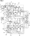
- FIG. 1 is a circuit configuration diagram of an integrated electric power steering apparatus according to Embodiment 1 of the present invention
- FIG. 1 represents a circuit configuration mainly including an electric motor and a control unit.
- the electric motor 2 is formed of a brushless motor provided with a stator having a first armature winding 201 and a second armature winding 202, which are independent from each other, and a rotor having magnetic-field poles formed of permanent magnets.
- the first armature winding 201 is formed of a three-phase winding in which a first U-phase winding U1, a first V-phase winding V1, and a first W-phase winding W1 are A-connected.
- the second armature winding 202 is formed of a three-phase winding in which a second U-phase winding U2, a second V-phase winding V2, and a second W-phase winding W3 are ⁇ -connected.
- the electric motor 2 may be a motor with a brush; moreover, each of the first armature winding 201 and the second armature winding 202 may be a multiphase winding of three phases or more. Furthermore, the electric motor 2 may be not a three-phase A-connection brushless motor but a three-phase Y-connection brushless motor or double-pole two-pair brush motor. With regard to the winding specification, distributed winding and concentrated winding can be adopted, as is the case with a conventional apparatus. Furthermore, the electric motor 2 may be a so-called tandem motor having two stators.
- the electric motor 2 is a brushless motor in which three-phase two groups of the armature windings 201 and 202 are A-connected; thus, a rotation sensor unit 16 for detecting the rotation position of the rotor of the electric motor 2 is formed as a dual system so as to secure the redundancy and is provided with a first rotation sensor 16a, a second rotation sensor 16b, and a rotation sensor rotor 16c (refer to FIG. 2 ) that is shared by the first rotation sensor 16a and the second rotation sensor 16b. As described later, the rotation sensor rotor 16c is fixed at the anti-output side of the output axle of the motor 2.
- the first rotation sensor 16a and the second rotation sensor 16b are arranged in such a way as to face the rotation sensor rotor 16c and to be spaced a predetermined gap apart from the rotation sensor rotor 16c in the axel direction.
- a battery 9 mounted in a vehicle, an ignition switch 7, and various kinds of sensors 8 such as a vehicle speed sensor and a torque sensor that detects steering torque on a handwheel are provided outside the electric power steering apparatus.
- a first control unit 1a is formed mainly of a first inverter circuit 3a that supplies electric power to the first armature winding 201 of the electric motor 2, a first control circuit unit 4a equipped with a first CPU 10a, a first power-source relay 5a, and a filter unit 6.
- the +B terminal and the GND terminal to be connected with the battery 9 and the filter unit 6 are utilized also in a second control unit 1b, described later.
- the first inverter circuit 3a is formed of a three-phase bridge circuit having a U-phase arm including a U-phase upper arm and a U-phase lower arm, a V-phase arm including a V-phase upper arm and a V-phase lower arm, and a W-phase arm including a W-phase upper arm and a W-phase lower arm.
- the U-phase upper arm has a U-phase upper arm switching device 31U
- the U-phase lower arm has a U-phase low arm switching device 32U.
- the V-phase upper arm has a V-phase upper arm switching device; the V-phase lower arm has a V-phase lower arm switching device; the W-phase upper arm has a W-phase upper arm switching device; the W-phase lower arm has a W-phase lower arm switching device.
- the reference characters of the switching devices other than the U-phase-arm switching devices are omitted. Each of these switching devices is formed of, for example, a MOSFET having a parasitic diode.
- the first inverter circuit 3a further has a noise-suppression first capacitor 30a that is connected between the GND and the connection portion between the U-phase upper arm and the V-phase upper arm and a noise-suppression second capacitor 30b that is connected between the GND and the connection portion between the V-phase upper arm and the W-phase upper arm.
- a first U-phase shunt resistor 33U, a first V-phase shunt resistor, and a first W-phase shunt resistor for detecting respective currents flowing in the first windings U1, V1, and W1 of the respective phases are connected with the U-phase lower arm switching device 32U, the V-phase lower arm switching device, and the W-phase lower arm switching device, respectively.
- the reference characters of the shunt resistors other than the U-phase-arm shunt resistor 33U are omitted.
- a U-phase output terminal pulled out from the connection point between the U-phase upper arm and the U-phase lower arm of the first inverter circuit 3a is connected with the winding terminal of the first U-phase winding U1 by way of a U-phase first motor switching device 34U.
- a V-phase output terminal pulled out from the connection point between the V-phase upper arm and the V-phase lower arm is connected with the winding terminal of the first V-phase winding V1 by way of a V-phase first motor switching device 34V.
- a W-phase output terminal pulled out from the connection point between the W-phase upper arm and the W-phase lower arm is connected with the winding terminal of the first W-phase winding W1 by way of a W-phase first motor switching device 34W.
- Each of the first motor switching devices 34U, 34V, and 34W of the respective phases is formed of, for example, a FET having a parasitic diode and has a function as a motor relay that opens or closes the path between the first armature winding 201 and the first inverter circuit 3a.
- the power source +B and the GND are connected with the battery 9 mounted in the vehicle; by means of an ignition switch 7, a power source is applied by way of a first power-supply circuit 13a of the first control circuit unit 4a.
- information pieces for example, from a torque sensor that is mounted in the vicinity of a handwheel (unillustrated) and detects steering torque produced by a driver, a speed sensor that detects the traveling speed of the vehicle, and the like are inputted from sensors 8.
- the filter unit 6 is shared by the first control unit 1a and the second control unit 1b.
- the power source 15 after the filter unit 6 is connected with the first control unit 1a and the second control unit 1b.
- the filter unit 6 is provided with a common mode coil 6a, a normal mode coil 6b, capacitors, and the like; however, it is made possible that depending on the magnitude of noise in the apparatus, only one of the foregoing coils is utilized and the number of the capacitors is adjusted.
- the filter unit 6 is provided in each of the first control unit 1a and the second control unit 1b.
- the second control unit 1b is formed mainly of a second inverter circuit 3b that supplies electric power to the second armature winding 202 of the electric motor 2, a second control circuit unit 4b equipped with a second CPU 10b, and a second power-source relay 5b.
- the +B terminal and the GND terminal to be connected with the battery 9 and the filter unit 6 provided in the foregoing first control unit 1a are utilized also in the second control unit 1b.
- the second inverter circuit 3b is formed of a three-phase bridge circuit having a U-phase arm including a U-phase upper arm and a U-phase lower arm, a V-phase arm including a V-phase upper arm and a V-phase lower arm, and a W-phase arm including a W-phase upper arm and a W-phase lower arm.
- the U-phase upper arm has a U-phase upper arm switching device 311U
- the U-phase lower arm has a U-phase lower arm switching device 321U.
- the V-phase upper arm has a V-phase upper arm switching device; the V-phase lower arm has a V-phase lower arm switching device; the W-phase upper arm has a W-phase upper arm switching device; the W-phase lower arm has a W-phase lower arm switching device.
- the reference characters of the switching devices other than the U-phase-arm switching devices are omitted. Each of these switching devices is formed of, for example, a MOSFET having a parasitic diode.
- the second inverter circuit 3b further has a noise-suppression third capacitor 301a that is connected between the GND and the connection portion between the U-phase upper arm and the V-phase upper arm and a noise-suppression fourth capacitor 301b that is connected between the GND and the connection portion between the V-phase upper arm and the W-phase upper arm.
- a second U-phase shunt resistor 331U, a first V-phase shunt resistor, and a first W-phase shunt resistor for detecting respective currents flowing in the second windings U2, V2, and W2 of the respective phases are connected with the U-phase lower arm switching device 32U, the V-phase lower arm switching device, and the W-phase lower arm switching device, respectively.
- the reference characters of the shunt resistors other than the U-phase-arm shunt resistor 331U are omitted.
- a U-phase output terminal pulled out from the connection point between the U-phase upper arm and the U-phase lower arm of the second inverter circuit 3b is connected with the winding terminal of the second U-phase winding U2 by way of a U-phase second motor switching device 341U.
- a V-phase output terminal pulled out from the connection point between the V-phase upper arm and the V-phase lower arm is connected with the winding terminal of the second V-phase winding V2 by way of a V-phase second motor switching device 341V.
- a W-phase output terminal pulled out from the connection point between the W-phase upper arm and the W-phase lower arm is connected with the winding terminal of the second W-phase winding W2 by way of a W-phase second motor switching device 341W.
- Each of the second motor switching devices 341U, 341V, and 341W of the respective phases is formed of, for example, a FET having a parasitic diode and has a function as a motor relay that opens or closes the path between the second armature winding 202 and the second inverter circuit 3b.
- the power source +B and the GND are connected with the battery 9 mounted in the vehicle; by means of the ignition switch 7, a power source is applied by way of a second power-supply circuit 13b of the second control circuit unit 4b.
- information pieces for example, from the torque sensor that is mounted in the vicinity of the handwheel (unillustrated) and detects steering torque produced by the driver, the speed sensor that detects the traveling speed of the vehicle, and the like are inputted from sensors 8.
- the first power-supply circuit 13a is supplied with electric power by the battery 9 so as to generate a predetermined DC constant voltage and to supply the DC constant voltage to the first CPU 10a, a first input circuit 12a, and a first driving circuit 11a in the first control unit 1a.
- the second power-supply circuit 13b is supplied with electric power by the battery 9 so as to generate a predetermined DC constant voltage and to supply the DC constant voltage to the second CPU 10b, a second input circuit 12b, and a second driving circuit 11b in the second control unit 1b.
- the battery 9 supplies a DC voltage to the first inverter circuit 3a and the second inverter circuit 3b, by way of the filter unit 6.
- Information pieces from the various kinds of sensors 8 such as the vehicle speed sensor and the torque sensor are inputted to the first CPU 10a by way of the first input circuit 12a; concurrently, the information pieces are inputted to the second CPU 10b by way of the second input circuit 12b.
- each of the first CPU 10a and the second CPU 10b calculates a control amount for supplying electric power to the electric motor 2; a first control command based on the result of the calculation by the first CPU 10a is provided to the first driving circuit 11a; a second control command based on the result of the calculation by the second CPU 10b is provided to the second driving circuit 11b.
- the first driving circuit 11a Based on the first control command from the first CPU 10a, the first driving circuit 11a performs PWM driving of the upper arm switching devices and the lower arm switching devices of the respective phases, such as the U-phase upper arm switching device 31U and the U-phase lower arm switching device 32U, in the first inverter circuit 3a. Similarly, based on the second control command from the second CPU 10b, the second driving circuit 11b performs PWM driving of the upper arm switching devices and the lower arm switching devices of the respective phases, such as the U-phase upper arm switching device 311U and the U-phase lower arm switching device 321U, in the second inverter circuit 3b.
- the first inverter circuit 3a supplies electric power to the first armature winding 201 of the electric motor 2, by way of the U-phase opening/closing switching device 34U, the V-phase opening/closing switching device 34V, and the W-phase opening/closing switching device 34W;
- the second inverter circuit 3b supplies electric power to the second armature winding 202 of the electric motor 2, by way of the U-phase switching device 341U, the V-phase switching device 341V, and the W-phase switching device 341W.
- the rotor of the electric motor 2 When undergoing a rotating magnetic field generated by the first armature winding 201 and the second armature winding 202, the rotor of the electric motor 2 produces predetermined rotation torque; the produced rotation torque, as auxiliary torque, is exerted on the steering shaft so as to assist the driver's steering.
- the voltage values or current values at respective portions of the first inverter circuit 3a and the second inverter circuit 3b and the information pieces on the rotation angle of the rotor of the electric motor 2 from the first rotation sensor 16a and the second rotation sensor 16b are transferred to the first CPU 10a and the second CPU 10b by way of the first input circuit 12a and the second input circuit 12b, respectively. Based on these transferred information pieces, the first CPU 10a performs feedback control of the first inverter circuit 3a and the second CPU 10b performs feedback control of the second inverter circuit 3b.
- commands from the first CPU 10a forcibly turn off the first power-source-relay switching device 5a and/or the motor switching devices 34U, 34V, and 34W, so that the first inverter circuit 3a and/or the first armature winding 201 can be disconnected from the battery 9.
- commands from the second CPU 10b forcibly turn off the second power-source-relay switching device 5b and/or the motor switching devices 341U, 341V, and 341W, so that the second inverter circuit 3b and/or the second armature winding 202 can be disconnected from the battery 9.
- the parasitic diodes in the first power-source-relay switching device 5a and the second power-source-relay switching device 5b cut off the lines in which the respective currents of the first inverter circuit 3a and the second inverter circuit 3b flow, so that the first inverter circuit 3a and the second inverter circuit 3b can be protected.
- the switching devices of the respective phases such as the U-phase upper arm switching device 31U and the U-phase lower arm switching device 32U, in the first inverter circuit 3a are PWM-driven based on the commands from the first CPU 10a; noise signals generated through the PWM driving are suppressed by the first capacitor 30a and the second capacitor 30b.
- the switching devices of the respective phases such as the U-phase upper arm switching device 311U and the U-phase lower arm switching device 321U, in the second inverter circuit 3b are PWM-driven based on the commands from the second CPU 10b; noise signals generated through the PWM driving are suppressed by the third capacitor 301a and the fourth capacitor 301b.
- the information, on the rotation angle of the rotor of the electric motor 2, that is detected by the first rotation sensor 16a is transferred to the first CPU 10a; the rotation position and/or the rotation speed of the electric motor are/is calculated and then are/is utilized in the feedback control of the first inverter circuit 3a and the like.
- the voltages and/or currents at the respective connection points between the upper arm switching devices and the lower arm switching devices of the respective phases are transferred to the second CPU 10b; the difference between a control command value (target value) and the actual current or voltage value is comprehended, and then so-called feedback control and a fault determination are performed.
- the information, on the rotation angle of the rotor of the electric motor 2, that is detected by the second rotation sensor 16b is transferred to the second CPU 10b; the rotation position and/or the rotation speed of the electric motor are/is calculated and then are/is utilized in the feedback control of the second inverter circuit 3b and the like.
- the first driving circuit 11a and the second driving circuit 11b are disposed in the first control circuit unit 4a and the second control circuit unit 4b, respectively, in Embodiment 1; however, it is made possible that the first driving circuit 11a is disposed in the first inverter circuit 3a and the second driving circuit 11b is disposed in the second inverter circuit 3b. It may be allowed that because a large current flows and hence heat is generated in each of them, the first power-source-relay switching device 5a and the second power-source-relay switching device 5b are included in the first inverter circuit 3a and the second inverter circuit 3b, respectively.
- each of the first control unit 1a and the second control unit 1b independently utilizes input information and the calculation value for a control amount and is capable of independently driving the electric motor 2.
- a communication line 14 is connected between the first control unit 1a and the second control unit 1b so that data and information can be transmitted and received therebetween.
- the communication line 14 connects the first CPU 10a with the second CPU 10b, so that the first CPU 10a can comprehend the condition of the second CPU 10b, and vice versa.
- the first CPU 10a detects that a failure has occurred in the first inverter circuit 3a or in the first armature winding 201 and turns off the first power-source-relay switching device 5a and/or the motor switching devices 34U, 34V, and 34W, information pieces on the contents of the abnormality detection, the subject component, the motor driving condition, and the like are transferred to the second CPU 10b.
- the second CPU 10b detects that a failure has occurred in the second inverter circuit 3b or in the second armature winding 202 and turns off the second power-source-relay switching device 5b and/or the motor switching devices 341U, 341V, and 341W, information pieces on the contents of the abnormality detection, the subject component, the motor driving condition, and the like are transferred to the first CPU 10a.
- first control circuit unit 4a the second control circuit unit 4b, and the respective components mounted therein can functionally drive the first armature winding 201 and the second armature winding 202 of the electric motor 2; thus, it may be allowed that instead of the two independent groups, a single configuration is utilized; for example, it may be allowed that only a single CPU or only a single power-supply circuit is provided.
- FIG. 2 is a cross-sectional view of the electric power steering apparatus according to Embodiment 1 of the present invention
- FIG. 3 is a plan view of the control unit in the electric power steering apparatus according to Embodiment 1 of the present invention.
- the electric motor 2 is situated at the lower part of the drawing; a control unit 1 including the first control unit 1a and the second control unit 1b is situated at the upper part of the drawing.
- the electric motor 2 and the control unit 1 are integrated with each other in such a way as to be arranged coaxially on the axis line of an output axle 21 of the electric motor 2.
- An electric-motor case 25 that is made of meatal and formed in the shape of a cylindrical tube has an end wall portion 250 in which a mounting flange portion 25a for mounting the electric power steering apparatus in a mechanism portion or the like of a vehicle and a connection portion 25b for mechanically connecting the electric power steering apparatus with a speed reducer (unillustrated) are integrally formed.
- the electric-motor case 25 is preferably formed of, for example, aluminum, when the heat radiation performance and the outer shape thereof are taken into consideration.
- a stator 22 and a rotor 23 of the electric motor 2 are contained in the electric-motor case 25.
- the output-side end portion in the axis direction of the output axle 21 of the electric motor 2 is pivotably supported by a first bearing 29b mounted in an end wall portion through-hole 251 provided in the radial-direction middle portion of the end wall portion 250, penetrates the end wall portion through-hole 251, and protrudes toward the speed reducer.
- the rotor 23 is fixed to the output axle 21; in the circumferential direction thereof, two or more pairs of magnetic-field poles, each of which is formed of a permanent magnet, are arranged.
- the circumferential surface of the rotor 23 is disposed in such a way as to face the inner circumferential surface of the stator 22 via a gap.
- the first armature winding 201 and the second armature winding 202 are mounted on the stator 22.
- the three first winding terminals 26a of the windings of the respective phases in the first armature winding 201 are electrically connected with respective connecting conductors of the connection ring 27 disposed in the right vicinity of the armature winding and extend in the axle direction of the electric motor 2 from the axel-direction endface of the connection ring 27 to the control unit 1.
- the three second winding terminals 26b of the windings of the respective phases in the second armature winding 202 are electrically connected with respective connecting conductors of the connection ring 27 and extend in the axle direction of the electric motor 2 from the axel-direction endface of the connection ring 27 to the control unit 1, at positions opposite to the first winding terminals 26a via the output axle 21.
- a frame 28 is mounted in such a way as to be inscribed to the end portion, at the anti-speed-reducer side in the axel direction, of the electric-motor case 25.
- the frame 28 is also made of metal; a second bearing 29a is mounted in a frame through-hole 281 formed in the radial-direction middle portion.
- the end portion, at the anti-output side, of the output axle 21 of the electric motor 2 is pivotably supported by the second bearing 29a.
- the rotation sensor rotor 16c described above, is fixed on the end portion at the anti-output side, of the output axle 21 of the electric motor 2.
- the frame 28 is provided with a first winding-terminal through-hole 28a through which the first winding terminal 26a passes and a second winding-terminal through-hole 28b through which the second winding terminal 26b passes.
- the first winding terminal 26a described above, penetrates the first winding-terminal through-hole 28a and then extends toward a control board 4 in the axle direction of the electric motor 2.
- the second winding terminal 26b described above, penetrates the second winding-terminal through-hole 28b and then extends toward the control board 4 in the axle direction of the electric motor 2.
- the frame 28 has two or more functions such as a function as a diaphragm for separating the electric motor 2 from the control unit 1 and a function of holding the second bearing 29a. Furthermore, the frame 28 also has a function as a heat sink for radiating the heat of the control unit 1. As described above, because the frame 28 has a great number of functions, the number of components can be reduced.
- the electric motor 2 has a structure in which the electric-motor case 25 contains the output axle 21, the rotor 23, the stator 22, the first armature winding 201, the second armature winding 202, the connection ring 27, the frame 28, the first bearing 29b, and the second bearing 29a. Accordingly, the electric motor 2 can be assembled separately from the control unit 1. The electric motor 2 and the control unit 1 are assembled separately from each other and then are integrated with each other.
- the control unit 1 includes the first control unit 1a and the second control unit 1b represented in FIG. 1 and is covered with a housing 40 fixed to the axel-direction end portion of the metal electric-motor case 25.
- An inner housing 46 described later, separates the inside of the housing 40 into a first room 41 and a second room 43.
- the first room 41 contains the control board 4 on which the control circuit unit including the first control circuit unit 4a and the second control circuit unit 4b is mounted.
- the CPU 10 including the first CPU 10a and the second CPU 10b is mounted on the surface, at the anti-electric-motor 2 side, of the control board 4. Both the first CPU 10a and the second CPU 10b, represented in FIG. 1 , of the CPU 10 are contained in a single package.
- the switching devices of the respective phases such as the U-phase upper arm switching device 31U and the U-phase lower arm switching device 32U, in the first inverter circuit 3a and the switching devices of the respective phases, such as the U-phase upper arm switching device 311U and the U-phase lower arm switching device 321U, in the second inverter circuit 3b are mounted on the surface, at the electric motor 2 side, of the control board 4 (in FIG. 2 , only the reference character 311U is represented).
- the first motor switching devices 34U, 34V, and 34W of the respective phases in the first inverter circuit 3a and the second motor switching devices 341U, 341V, and 341W of the respective phases in the second inverter circuit 3b are mounted on the surface, at the electric motor 2 side, of the control board 4 (in FIG. 2 , only the reference character 34U is represented).
- the first winding terminal 26a penetrates the first winding-terminal through-hole 28a, passes through the peripheral portion of the control board 4, and further penetrates a penetration opening in the housing 40 so as to extend to the outside of the housing 40.
- the first winding terminal 26a extends in the axle direction of the electric motor 2.
- the second winding terminals 26b penetrates the second winding-terminal through-hole 28b, passes through the peripheral portion of the control board 4, and further penetrates a penetration opening in the housing 40 so as to extend to the outside of the housing 40.
- the inner housing 46 is disposed inside the housing 40 and is fixed to the axel-direction end portion of the frame 28.
- the inner housing 46 is made of, for example, an insulative resin; the filter unit 6 represented in FIG. 1 is mounted thereon.
- the inner housing 46 has a role of fixing first electric conductors 451a from the switching devices of the respective phases, such as the U-phase upper arm switching device 31U and the U-phase lower arm switching device 32U, in the first inverter circuit 3a, the first motor switching devices 34U, 34V, and 34W, and the like and second electric conductors 451b from the switching devices of the respective phases, such as the U-phase upper arm switching device 311U and the U-phase lower arm switching device 321U, in the second inverter circuit 3b, the second motor switching devices 341U, 341V, and 341W, and the like. Furthermore, the inner housing 46 has a role of fixing bus bars 45a and 45b connected with the filter unit 6. When covered with a metal plate, the inner housing 46 can be utilized as a shielding wall for separating the control board 4 from the filter unit 6.
- the filter unit 6, described above, is contained in the second room 43 of the housing 40.
- the housing 40 is formed in such a way that the portion that corresponds to the second room 43 protrudes toward the anti-electric-motor 2 side.
- a power-source connector 42 provided with the +B terminal and the GND terminal is disposed in the portion, of the housing 40, that corresponds to the second room 43.
- the power-source connector 42 and the housing 40 are integrated with each other and are made of resin.
- the switching control of the power switching devices such as the switching devices 311U and 34U, mounted on the surface, at the electric motor 2 side, of the control board 4 causes heat generation. Accordingly, those power switching devices are arranged in such a way that the surfaces thereof abut on the surface of the frame 28 so that the heat can be transferred to the frame 28. In other words, the frame 28 has a role also as a heat sink.
- each of the first winding terminal 26a and the second winding terminals 26b passes through the peripheral portion of the control board 4 and penetrates the housing 40 so as to extend to the outside of the housing 40.
- the first electric conductor 451a and the second electric conductor 451b from the switching devices, such as the switching devices 311U and 34U, on the control board 4 also penetrate the housing 40 so as to extend to the outside of the housing 40 and are electrically connected with the front-end portions of the winding terminals 26a and 26b, respectively, for example, through welding. These respective connection portions are covered with covers 47a and 47b.
- connection portion between the first winding terminal 26a and the first electric conductor 451a and the connection portion between the second winding terminals 26b and the second electric conductor 451b are arranged outside the housing 40, the workability of connecting these members is raised. For example, it is not required to consider spatters caused by the welding and the arrangement of welding tools; thus, the working efficiency is remarkably raised in comparison with the case where the welding is performed inside the control unit 1.
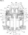
- FIG. 3 is an explanatory view of the control unit in the electric power steering apparatus according to Embodiment 1 of the present invention.
- the electric conductors extending from the +B terminal and the GND terminal in the power-source connector 42 to the control board 4 via the filter unit 6 are the portions that are directly connected therebetween, as illustrated in the circuit in FIG. 1 ; thus, because the current that flows in each of the electric conductors is large, the width and the thickness thereof need to correspond to the current and hence downsizing is hindered. Therefore, the power-source connector 42 is disposed at the substantially middle portion of the housing 40, as illustrated in FIG. 3 .
- the power-source connector 42 has the +B terminal and the GND terminal; these respective terminals extend in the housing 40 and are connected with the bus bar 45a and 45b, respectively.
- the respective components in the filter unit 6 in FIG. 1 are connected with the bus bars 45a and 45b.
- a common mode coil 6a and a normal mode coil 6b are arranged in that order and are connected with the bus bars 45a and 45b, respectively.
- the power-source connector 42 and the components in the filter unit 6, which is a large component are sterically arranged and hence the mounting area is reduced, so that the downsizing is implemented.
- a first signal connector 48a and a second signal connector 48b for the sensors 8 are arranged from side to side in the housing 40 in such a way as to be separated from each other.
- the first signal connector 48a is connected with the first input circuit 12a of the first control circuit unit 4a; the second signal connector 48b is connected with the second input circuit 12b of the second control circuit unit 4b.
- the first winding terminal 26a and the second winding terminals 26b are arranged substantially symmetrically in the peripheral portion of the housing 40 in such a way as to flank the filter unit 6 and are connected with the first electric conductor 451a and the second electric conductor 451b, respectively.
- the connection position between the first winding terminal 26a and the first electric conductor 451a and the connection position between the second winding terminals 26b and the second electric conductor 451b are arranged substantially symmetrically with respect to the middle portion of the housing 40.
- the first signal connector 48a and the second signal connector 48b are arranged in the vicinity of the housing 40, and the connection portion between the first winding terminal 26a and the first electric conductor 451a and the connection portion between the second winding terminals 26b and the second electric conductor 451b are arranged in the vicinity of the housing 40; therefore, because the conductive wires extending from these members are arranged in the peripheral portion or in the vicinity of the control board 4, the effective area of the control board 4 is not reduced.
- the electric power steering apparatus has a two-storied structure in which the control unit 1 is mounted on the axle-direction end portion, at the anti-electric-motor side, of the output axle 21 of the electric motor 2 so as to be integrated with the electric motor 2, in which the power-source connector is disposed at the substantially middle portion of the housing of the control unit 1, and in which the filter unit 6 is disposed under the power-source connector, and the winding terminals and the signal connectors are arranged in the peripheral portion of the housing 40; thus, the respective components can be arranged within a diameter the same as that of the motor 2 and hence the downsizing can be implemented.
- This arrangement makes it possible that the wiring leads that start from the power-source terminal and then pass through the filter unit 6 can be shortened as much as possible. Furthermore, because the respective connection positons between the winding terminals 26a and 26b and the switching devices are situated in the peripheral side of the housing, the working efficiency can be raised.
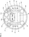
- FIG. 4 is a cross-sectional view of the electric power steering apparatus according to Embodiment 2 of the present invention
- FIG. 5 is an explanatory view of a control unit in the electric power steering apparatus according to Embodiment 2 of the present invention
- the elements the same as or equivalent to those in FIGS. 1 , 2 , and 3 are designated by the same reference characters.
- Embodiment 1 and Embodiment 2 are the connection structures of the first winding terminal 26a and the second winding terminals 26b of the electric motor 2 and the arrangement of the first capacitor 30a, the second capacitor 30b, the third capacitor 301a, and the fourth capacitor 301b in the control unit 1.
- the control unit 1 is disposed at the axle-direction anti-output side of the electric motor 2 in such a way as to be coaxial with the output axle 21 of the electric motor 2.
- the three first winding terminals 26a of the windings of the respective phases in the first armature winding 201 are electrically connected with respective connecting conductors of the connection ring 27 disposed in the right vicinity of the armature winding and extend in the axle direction of the electric motor 2 from the axel-direction endface of the connection ring 27 to the control unit 1; however, the front-end portions thereof do not penetrate the housing 40 but stay within the housing 40.
- the three second winding terminals 26b of the windings of the respective phases in the second armature winding 202 are electrically connected with respective connecting conductors of the connection ring 27 and extend in the axle direction of the electric motor 2 from the axel-direction endface of the connection ring 27 to the control unit 1, at positions opposite to the first winding terminals 26a via the output axle 21; however, the front-end portions thereof do not penetrate the housing 40 but stay within the housing 40.
- a terminal 50 is provided on the control board 4.
- the terminal 50 includes a conductive plate 50a and an insulative resin portion 50b. Via the strip conductor of the control board 4, one end of the conductive plate 50a is connected with the switching devices 31U, 31V, and 31W of the respective arms of the first inverter circuit 3a or the switching devices 311U, 311V, and 311W of the respective arms of the second inverter circuit 3b (in FIG. 4 , only the reference character 311U is expressed) and the first motor switching devices 34U, 34V, 34W of the respective phases of the first inverter circuit 3a or the second motor switching devices 341U, 341V, 341W of the respective phases of the second inverter circuit 3b (in FIG. 4 , only the reference character 34U is expressed).
- the other end of the conductive plate 50a is covered with the insulative resin portion 50b; window portions are provided in the insulative resin portion 50b, and the conductive plates 50a are disposed in the window portions in such a way as to be separated into at least two pieces each in a fork-shaped manner.
- FIG. 5 illustrates that two pieces each of the fork-shaped conductive plates 50a are arranged.
- Each of the first winding terminal 26a and the second winding terminals 26b is inserted between the portions of the conductive plate 50a, which are separated in a fork-shaped manner, fitted with the conductive plate 50a, and electrically connected with the conductive plate 50a through press-fitting.
- Part of the insulative resin portion 50b abuts on the inner housing 46; through the abutting, there are performed positioning of the terminal 50 and supporting of the pressure at a time when each of the first winding terminal 26a and the second winding terminals 26b is inserted into the conductive plate 50a.
- the first capacitor 30a and the second capacitor 30b for suppressing noise from the switching devices of the first inverter circuit 3a represented in FIG. 1 and the third capacitor 301a and the fourth capacitor 301b for suppressing noise from the switching devices of the second inverter circuit 3b represented in FIG. 1 are connected with the control board 4.
- These capacitors 30a, 30b, 301a, and 301b are mounted on the control board 4; because being relatively large components, these capacitors 30a, 30b, 301a, and 301b penetrate penetration openings provided in the inner housing 46 and extend in such a way as to go beyond the endface of the housing 40, as illustrated in FIG. 4 .
- these capacitors 30a, 30b, 301a, and 301b are arranged in the surroundings of the filter unit 6, described also in Embodiment 1.
- the housing 40 has tubular protrusions 41a, 411a, 41b, and 411b at the respective positions corresponding to these capacitors 30a, 30b, 301a, and 301b; the capacitors 30a, 30b, 301a, and 301b are partially contained in the tubular protrusions 41a, 411a, 41b, and 411b, respectively.
- the protrusions 41a, 411a, 41b, and 411b for the capacitors can sterically be arranged without overlapping with the filter unit 6 and the power-source connector 42.
- the capacitors 30a, 30b, 301a, and 301b are arranged at respective positions that are substantially symmetric with one another. This is because each of the first inverter circuit 3a and the second inverter circuit 3b has the same circuit configuration and the constituent components of each of the first inverter circuit 3a and the second inverter circuit 3b are arranged in the same manner; as a result, the capacitors 30a, 30b, 301a, and 301b can be arranged in such a way as to be symmetric with the respective corresponding capacitors. This symmetric arrangement suppresses as much as possible the electrical difference between the first inverter circuit 3a and the second inverter circuit 3b, for example, the difference in the circuitry impedance.
- the connection between the winding terminals and the control circuit units is performed within the control unit 1; therefore, the assembly can be simplified. Moreover, it is made possible that the capacitors having a large height can be contained in the protrusions provided in the housing 40 and hence it is made possible that without enlarging the diameter of the electric motor 2, all portions can be arranged within the diameter of the electric motor 2; therefore, the downsizing can be achieved.
- Embodiments 1 and 2 are not limited to the respective electric power steering driving apparatuses according to foregoing Embodiments 1 and 2; within the scope of the appended claims the respective configurations of Embodiments 1 and 2 can appropriately be combined with each other, can partially be modified, or can partially be omitted.
Landscapes
- Engineering & Computer Science (AREA)
- Power Engineering (AREA)
- Chemical & Material Sciences (AREA)
- Combustion & Propulsion (AREA)
- Transportation (AREA)
- Mechanical Engineering (AREA)
- Microelectronics & Electronic Packaging (AREA)
- Power Steering Mechanism (AREA)
- Motor Or Generator Frames (AREA)
Description
- The present invention relates to a vehicle electric power steering apparatus, particularly to an electric power steering apparatus in which a motor and a control unit are integrated.
- As is well known, an electric power steering apparatus is configured in such a way that an electric motor produces auxiliary torque corresponding to steering torque that is exerted by a driver on the steering system of a vehicle and then the auxiliary torque is exerted on the steering system so as to assist the driver's steering. To date, there has practically been utilized an electric power steering apparatus in which a single electric motor has two groups of armature windings, configured in the same manner, and a control unit is provided with two groups of inverter circuits that can independently drive the two groups of armature windings. Such an electric power steering apparatus is configured in such a way that control is performed by making the two groups of inverter circuits collaborate with each other and in such a way that when an abnormality exists in a control system including one of the inverter circuits, only a control system including the other one of the inverter circuits, which is normal, continues driving of the electric motor so that steering of the vehicle is prevented from becoming impossible and hence the safety of the vehicle is secured.
- To date, in such an electric power steering apparatus as described above, there have been disclosed configurations in each of which an electric motor and a control unit are coaxially arranged on the axis line of the output axle of the electric motor and the control unit is disposed at the anti-output side of the electric motor so that the electric motor and the control unit are integrated (e.g., refer to
JP 2015-154673 A JP 2015-154673 A US 2016/036304 A1 ,US 2013/257232 A1 ,WO 2015/145630 A1 , andUS 2013/249335 A1 . - Because the conventional electric power steering apparatus disclosed in
Patent Document 1 is configured in such a manner as described above, the winding end portions of the armature windings and large components such as the capacitor and the choke coil occupy a large area in the inner space of the control unit cover and hence downsizing of the electric power steering apparatus is hindered. - The present invention has been implemented in order to solve the foregoing problem in a conventional electric power steering apparatus; the objective thereof is to provide an electric power steering apparatus that can be downsized by optimizing the arrangement of the components.
- The electric power steering apparatus of the present invention is defined by
independent claim 1. Dependent claims are related to optional features and particular embodiments. - An electric power steering apparatus according to the present invention includes
an electric motor that has two groups of armature windings having the same configuration and generates assist torque corresponding to steering torque produced by a vehicle driver,
a control unit that has two groups of control circuit units capable of separately controlling the two groups of armature windings and that is disposed on the axle-direction end portion, at the anti-output side, of the electric motor so as to be integrally fixed to the electric motor, and
a housing that is fixed to the electric motor and covers the control unit; the electric power steering apparatus is characterized
in that the control unit includes - a power-source connector that connects the control unit with an external power source,
- a first connection portion where the winding terminal of the armature winding of one of the two groups of armature windings is connected with one of the two groups of control circuit units,
- a second connection portion where the winding terminal of the armature winding of the other one of the two groups of armature windings is connected with the other one of the two groups of control circuit units,
- In an electric power steering apparatus according to the present invention, the control unit includes a power-source connector that connects the control unit with an external power source, a first connection portion where the winding terminal of the armature winding of one of the two groups of armature windings is connected with one of the two groups of control circuit units, and a second connection portion where the winding terminal of the armature winding of the other one of the two groups of armature windings is connected with the other one of the two groups of control circuit units; a power-source connector is situated at or in the vicinity of the radial-direction middle portion of a housing and is fixed to the housing; the first connection portion and the second connection portion are substantially symmetrically arranged at positions corresponding to the radial-direction peripheral portions of the power-source connector; thus, all portions of the control unit can be arranged within the diameter of the motor and hence downsizing can be achieved.
-
-
FIG. 1 is a circuit configuration diagram of an electric power steering apparatus according to any one ofEmbodiments -
FIG. 2 is a cross-sectional view of the electric power steering apparatus according toEmbodiment 1 of the present invention; -
FIG. 3 is an explanatory view of a control unit in the electric power steering apparatus according toEmbodiment 1 of the present invention; -
FIG. 4 is a cross-sectional view of the electric power steering apparatus according toEmbodiment 2 of the present invention; and -
FIG. 5 is an explanatory view of a control unit in the electric power steering apparatus according toEmbodiment 2 of the present invention. - Hereinafter,
Embodiment 1 of the present invention will be explained based on the drawings.FIG. 1 is a circuit configuration diagram of an integrated electric power steering apparatus according toEmbodiment 1 of the present invention;FIG. 1 represents a circuit configuration mainly including an electric motor and a control unit. InFIG. 1 , inEmbodiment 1, theelectric motor 2 is formed of a brushless motor provided with a stator having a first armature winding 201 and a second armature winding 202, which are independent from each other, and a rotor having magnetic-field poles formed of permanent magnets. The first armature winding 201 is formed of a three-phase winding in which a first U-phase winding U1, a first V-phase winding V1, and a first W-phase winding W1 are A-connected. The second armature winding 202 is formed of a three-phase winding in which a second U-phase winding U2, a second V-phase winding V2, and a second W-phase winding W3 are Δ-connected. - The
electric motor 2 may be a motor with a brush; moreover, each of the first armature winding 201 and the second armature winding 202 may be a multiphase winding of three phases or more. Furthermore, theelectric motor 2 may be not a three-phase A-connection brushless motor but a three-phase Y-connection brushless motor or double-pole two-pair brush motor. With regard to the winding specification, distributed winding and concentrated winding can be adopted, as is the case with a conventional apparatus. Furthermore, theelectric motor 2 may be a so-called tandem motor having two stators. - In
Embodiment 1, as described above, theelectric motor 2 is a brushless motor in which three-phase two groups of thearmature windings rotation sensor unit 16 for detecting the rotation position of the rotor of theelectric motor 2 is formed as a dual system so as to secure the redundancy and is provided with afirst rotation sensor 16a, asecond rotation sensor 16b, and arotation sensor rotor 16c (refer toFIG. 2 ) that is shared by thefirst rotation sensor 16a and thesecond rotation sensor 16b. As described later, therotation sensor rotor 16c is fixed at the anti-output side of the output axle of themotor 2. Thefirst rotation sensor 16a and thesecond rotation sensor 16b are arranged in such a way as to face therotation sensor rotor 16c and to be spaced a predetermined gap apart from therotation sensor rotor 16c in the axel direction. Abattery 9 mounted in a vehicle, anignition switch 7, and various kinds ofsensors 8 such as a vehicle speed sensor and a torque sensor that detects steering torque on a handwheel are provided outside the electric power steering apparatus. - A
first control unit 1a is formed mainly of afirst inverter circuit 3a that supplies electric power to the first armature winding 201 of theelectric motor 2, a firstcontrol circuit unit 4a equipped with afirst CPU 10a, a first power-source relay 5a, and afilter unit 6. The +B terminal and the GND terminal to be connected with thebattery 9 and thefilter unit 6 are utilized also in asecond control unit 1b, described later. - The
first inverter circuit 3a is formed of a three-phase bridge circuit having a U-phase arm including a U-phase upper arm and a U-phase lower arm, a V-phase arm including a V-phase upper arm and a V-phase lower arm, and a W-phase arm including a W-phase upper arm and a W-phase lower arm. The U-phase upper arm has a U-phase upperarm switching device 31U, and the U-phase lower arm has a U-phase lowarm switching device 32U. Similarly, the V-phase upper arm has a V-phase upper arm switching device; the V-phase lower arm has a V-phase lower arm switching device; the W-phase upper arm has a W-phase upper arm switching device; the W-phase lower arm has a W-phase lower arm switching device. For the sake of avoiding the complexity of the drawing, the reference characters of the switching devices other than the U-phase-arm switching devices are omitted. Each of these switching devices is formed of, for example, a MOSFET having a parasitic diode. - The
first inverter circuit 3a further has a noise-suppressionfirst capacitor 30a that is connected between the GND and the connection portion between the U-phase upper arm and the V-phase upper arm and a noise-suppressionsecond capacitor 30b that is connected between the GND and the connection portion between the V-phase upper arm and the W-phase upper arm. A firstU-phase shunt resistor 33U, a first V-phase shunt resistor, and a first W-phase shunt resistor for detecting respective currents flowing in the first windings U1, V1, and W1 of the respective phases are connected with the U-phase lowerarm switching device 32U, the V-phase lower arm switching device, and the W-phase lower arm switching device, respectively. For the sake of avoiding the complexity of the drawing, the reference characters of the shunt resistors other than the U-phase-arm shunt resistor 33U are omitted. - A U-phase output terminal pulled out from the connection point between the U-phase upper arm and the U-phase lower arm of the
first inverter circuit 3a is connected with the winding terminal of the first U-phase winding U1 by way of a U-phase firstmotor switching device 34U. Similarly, a V-phase output terminal pulled out from the connection point between the V-phase upper arm and the V-phase lower arm is connected with the winding terminal of the first V-phase winding V1 by way of a V-phase firstmotor switching device 34V. Moreover, a W-phase output terminal pulled out from the connection point between the W-phase upper arm and the W-phase lower arm is connected with the winding terminal of the first W-phase winding W1 by way of a W-phase firstmotor switching device 34W. Each of the firstmotor switching devices first inverter circuit 3a. - The power source +B and the GND are connected with the
battery 9 mounted in the vehicle; by means of anignition switch 7, a power source is applied by way of a first power-supply circuit 13a of the firstcontrol circuit unit 4a. Moreover, information pieces, for example, from a torque sensor that is mounted in the vicinity of a handwheel (unillustrated) and detects steering torque produced by a driver, a speed sensor that detects the traveling speed of the vehicle, and the like are inputted fromsensors 8. As described above, thefilter unit 6 is shared by thefirst control unit 1a and thesecond control unit 1b. Thepower source 15 after thefilter unit 6 is connected with thefirst control unit 1a and thesecond control unit 1b. Thefilter unit 6 is provided with acommon mode coil 6a, anormal mode coil 6b, capacitors, and the like; however, it is made possible that depending on the magnitude of noise in the apparatus, only one of the foregoing coils is utilized and the number of the capacitors is adjusted. - It may be allowed that the
filter unit 6 is provided in each of thefirst control unit 1a and thesecond control unit 1b. - The
second control unit 1b is formed mainly of asecond inverter circuit 3b that supplies electric power to the second armature winding 202 of theelectric motor 2, a secondcontrol circuit unit 4b equipped with asecond CPU 10b, and a second power-source relay 5b. The +B terminal and the GND terminal to be connected with thebattery 9 and thefilter unit 6 provided in the foregoingfirst control unit 1a are utilized also in thesecond control unit 1b. - The
second inverter circuit 3b is formed of a three-phase bridge circuit having a U-phase arm including a U-phase upper arm and a U-phase lower arm, a V-phase arm including a V-phase upper arm and a V-phase lower arm, and a W-phase arm including a W-phase upper arm and a W-phase lower arm. The U-phase upper arm has a U-phase upperarm switching device 311U, and the U-phase lower arm has a U-phase lowerarm switching device 321U. Similarly, the V-phase upper arm has a V-phase upper arm switching device; the V-phase lower arm has a V-phase lower arm switching device; the W-phase upper arm has a W-phase upper arm switching device; the W-phase lower arm has a W-phase lower arm switching device. For the sake of avoiding the complexity of the drawing, the reference characters of the switching devices other than the U-phase-arm switching devices are omitted. Each of these switching devices is formed of, for example, a MOSFET having a parasitic diode. - The
second inverter circuit 3b further has a noise-suppressionthird capacitor 301a that is connected between the GND and the connection portion between the U-phase upper arm and the V-phase upper arm and a noise-suppressionfourth capacitor 301b that is connected between the GND and the connection portion between the V-phase upper arm and the W-phase upper arm. A secondU-phase shunt resistor 331U, a first V-phase shunt resistor, and a first W-phase shunt resistor for detecting respective currents flowing in the second windings U2, V2, and W2 of the respective phases are connected with the U-phase lowerarm switching device 32U, the V-phase lower arm switching device, and the W-phase lower arm switching device, respectively. For the sake of avoiding the complexity of the drawing, the reference characters of the shunt resistors other than the U-phase-arm shunt resistor 331U are omitted. - A U-phase output terminal pulled out from the connection point between the U-phase upper arm and the U-phase lower arm of the
second inverter circuit 3b is connected with the winding terminal of the second U-phase winding U2 by way of a U-phase secondmotor switching device 341U. Similarly, a V-phase output terminal pulled out from the connection point between the V-phase upper arm and the V-phase lower arm is connected with the winding terminal of the second V-phase winding V2 by way of a V-phase secondmotor switching device 341V. Moreover, a W-phase output terminal pulled out from the connection point between the W-phase upper arm and the W-phase lower arm is connected with the winding terminal of the second W-phase winding W2 by way of a W-phase secondmotor switching device 341W. Each of the secondmotor switching devices second inverter circuit 3b. - The power source +B and the GND are connected with the
battery 9 mounted in the vehicle; by means of theignition switch 7, a power source is applied by way of a second power-supply circuit 13b of the secondcontrol circuit unit 4b. Moreover, information pieces, for example, from the torque sensor that is mounted in the vicinity of the handwheel (unillustrated) and detects steering torque produced by the driver, the speed sensor that detects the traveling speed of the vehicle, and the like are inputted fromsensors 8. - In the integrated electric power steering apparatus, according to
Embodiment 1 of the present invention, that is configured in such a manner as described above, when the driver turns on theignition switch 7, the first power-supply circuit 13a is supplied with electric power by thebattery 9 so as to generate a predetermined DC constant voltage and to supply the DC constant voltage to thefirst CPU 10a, afirst input circuit 12a, and afirst driving circuit 11a in thefirst control unit 1a. The second power-supply circuit 13b is supplied with electric power by thebattery 9 so as to generate a predetermined DC constant voltage and to supply the DC constant voltage to thesecond CPU 10b, asecond input circuit 12b, and asecond driving circuit 11b in thesecond control unit 1b. Furthermore, thebattery 9 supplies a DC voltage to thefirst inverter circuit 3a and thesecond inverter circuit 3b, by way of thefilter unit 6. - Information pieces from the various kinds of
sensors 8 such as the vehicle speed sensor and the torque sensor are inputted to thefirst CPU 10a by way of thefirst input circuit 12a; concurrently, the information pieces are inputted to thesecond CPU 10b by way of thesecond input circuit 12b. Based on these inputted information pieces, each of thefirst CPU 10a and thesecond CPU 10b calculates a control amount for supplying electric power to theelectric motor 2; a first control command based on the result of the calculation by thefirst CPU 10a is provided to thefirst driving circuit 11a; a second control command based on the result of the calculation by thesecond CPU 10b is provided to thesecond driving circuit 11b. - Based on the first control command from the
first CPU 10a, thefirst driving circuit 11a performs PWM driving of the upper arm switching devices and the lower arm switching devices of the respective phases, such as the U-phase upperarm switching device 31U and the U-phase lowerarm switching device 32U, in thefirst inverter circuit 3a. Similarly, based on the second control command from thesecond CPU 10b, thesecond driving circuit 11b performs PWM driving of the upper arm switching devices and the lower arm switching devices of the respective phases, such as the U-phase upperarm switching device 311U and the U-phase lowerarm switching device 321U, in thesecond inverter circuit 3b. - The
first inverter circuit 3a supplies electric power to the first armature winding 201 of theelectric motor 2, by way of the U-phase opening/closing switching device 34U, the V-phase opening/closing switching device 34V, and the W-phase opening/closing switching device 34W; thesecond inverter circuit 3b supplies electric power to the second armature winding 202 of theelectric motor 2, by way of theU-phase switching device 341U, the V-phase switching device 341V, and the W-phase switching device 341W. When undergoing a rotating magnetic field generated by the first armature winding 201 and the second armature winding 202, the rotor of theelectric motor 2 produces predetermined rotation torque; the produced rotation torque, as auxiliary torque, is exerted on the steering shaft so as to assist the driver's steering. - The voltage values or current values at respective portions of the
first inverter circuit 3a and thesecond inverter circuit 3b and the information pieces on the rotation angle of the rotor of theelectric motor 2 from thefirst rotation sensor 16a and thesecond rotation sensor 16b are transferred to thefirst CPU 10a and thesecond CPU 10b by way of thefirst input circuit 12a and thesecond input circuit 12b, respectively. Based on these transferred information pieces, thefirst CPU 10a performs feedback control of thefirst inverter circuit 3a and thesecond CPU 10b performs feedback control of thesecond inverter circuit 3b. - In the case where a failure occurs in the
first inverter circuit 3a or in the case where a failure occurs in the first armature winding 201, commands from thefirst CPU 10a forcibly turn off the first power-source-relay switching device 5a and/or themotor switching devices first inverter circuit 3a and/or the first armature winding 201 can be disconnected from thebattery 9. - Similarly, in the case where a failure occurs in the
second inverter circuit 3b or in the case where a failure occurs in the second armature winding 202, commands from thesecond CPU 10b forcibly turn off the second power-source-relay switching device 5b and/or themotor switching devices second inverter circuit 3b and/or the second armature winding 202 can be disconnected from thebattery 9. - Furthermore, even when the
battery 9 is connected in such a way that the polarity thereof is reversed, the parasitic diodes in the first power-source-relay switching device 5a and the second power-source-relay switching device 5b cut off the lines in which the respective currents of thefirst inverter circuit 3a and thesecond inverter circuit 3b flow, so that thefirst inverter circuit 3a and thesecond inverter circuit 3b can be protected. - The switching devices of the respective phases, such as the U-phase upper
arm switching device 31U and the U-phase lowerarm switching device 32U, in thefirst inverter circuit 3a are PWM-driven based on the commands from thefirst CPU 10a; noise signals generated through the PWM driving are suppressed by thefirst capacitor 30a and thesecond capacitor 30b. Similarly, the switching devices of the respective phases, such as the U-phase upperarm switching device 311U and the U-phase lowerarm switching device 321U, in thesecond inverter circuit 3b are PWM-driven based on the commands from thesecond CPU 10b; noise signals generated through the PWM driving are suppressed by thethird capacitor 301a and thefourth capacitor 301b. - The voltages and/or currents at the respective connection points between the upper arm switching devices and the lower arm switching devices of the respective phases, such as the connection point between the U-phase upper
arm switching device 31U and the U-phase lowerarm switching device 32U and the like, the voltages and/or currents at the shunt resistors of the respective phases, such as theU-phase shunt resistor 33U and the like, and the respective inter-winding-terminal voltages and/or currents of the first U-phase winding U1, the first V-phase winding V1, and the first W-phase winding W1 of the first armature winding 201 in thefirst inverter circuit 3a are transferred to thefirst CPU 10a; the difference between a control command value (target value) and the actual current or voltage value is comprehended, and then so-called feedback control and a fault determination are performed. The information, on the rotation angle of the rotor of theelectric motor 2, that is detected by thefirst rotation sensor 16a is transferred to thefirst CPU 10a; the rotation position and/or the rotation speed of the electric motor are/is calculated and then are/is utilized in the feedback control of thefirst inverter circuit 3a and the like. - The voltages and/or currents at the respective connection points between the upper arm switching devices and the lower arm switching devices of the respective phases, such as the connection point between the U-phase upper
arm switching device 311U and the U-phase lowerarm switching device 321U and the like, the voltages and/or currents at the shunt resistors of the respective phases, such as theU-phase shunt resistor 331U and the like, and the respective inter-winding-terminal voltages and/or currents of the second U-phase winding U2, the second V-phase winding V2, and the second W-phase winding W2 of the second armature winding 202 in thesecond inverter circuit 3b are transferred to thesecond CPU 10b; the difference between a control command value (target value) and the actual current or voltage value is comprehended, and then so-called feedback control and a fault determination are performed. The information, on the rotation angle of the rotor of theelectric motor 2, that is detected by thesecond rotation sensor 16b is transferred to thesecond CPU 10b; the rotation position and/or the rotation speed of the electric motor are/is calculated and then are/is utilized in the feedback control of thesecond inverter circuit 3b and the like. - Because the respective currents that flow in the
first driving circuit 11a and thesecond driving circuit 11b are small, thefirst driving circuit 11a and thesecond driving circuit 11b are disposed in the firstcontrol circuit unit 4a and the secondcontrol circuit unit 4b, respectively, inEmbodiment 1; however, it is made possible that thefirst driving circuit 11a is disposed in thefirst inverter circuit 3a and thesecond driving circuit 11b is disposed in thesecond inverter circuit 3b. It may be allowed that because a large current flows and hence heat is generated in each of them, the first power-source-relay switching device 5a and the second power-source-relay switching device 5b are included in thefirst inverter circuit 3a and thesecond inverter circuit 3b, respectively. - As described above, each of the
first control unit 1a and thesecond control unit 1b independently utilizes input information and the calculation value for a control amount and is capable of independently driving theelectric motor 2. Acommunication line 14 is connected between thefirst control unit 1a and thesecond control unit 1b so that data and information can be transmitted and received therebetween. Thecommunication line 14 connects thefirst CPU 10a with thesecond CPU 10b, so that thefirst CPU 10a can comprehend the condition of thesecond CPU 10b, and vice versa. - For example, when the
first CPU 10a detects that a failure has occurred in thefirst inverter circuit 3a or in the first armature winding 201 and turns off the first power-source-relay switching device 5a and/or themotor switching devices second CPU 10b. Similarly, when thesecond CPU 10b detects that a failure has occurred in thesecond inverter circuit 3b or in the second armature winding 202 and turns off the second power-source-relay switching device 5b and/or themotor switching devices first CPU 10a. - It is only necessary that the first
control circuit unit 4a, the secondcontrol circuit unit 4b, and the respective components mounted therein can functionally drive the first armature winding 201 and the second armature winding 202 of theelectric motor 2; thus, it may be allowed that instead of the two independent groups, a single configuration is utilized; for example, it may be allowed that only a single CPU or only a single power-supply circuit is provided. - Next, there will be explained the integrated configuration in which the
electric motor 2, thefirst control unit 1a, and thesecond control unit 1b of the electric power steering apparatus, according toEmbodiment 1 of the present invention, that has a foregoing circuit configuration.FIG. 2 is a cross-sectional view of the electric power steering apparatus according toEmbodiment 1 of the present invention;FIG. 3 is a plan view of the control unit in the electric power steering apparatus according toEmbodiment 1 of the present invention. InFIG. 2 , theelectric motor 2 is situated at the lower part of the drawing; acontrol unit 1 including thefirst control unit 1a and thesecond control unit 1b is situated at the upper part of the drawing. Theelectric motor 2 and thecontrol unit 1 are integrated with each other in such a way as to be arranged coaxially on the axis line of anoutput axle 21 of theelectric motor 2. - An electric-
motor case 25 that is made of meatal and formed in the shape of a cylindrical tube has anend wall portion 250 in which a mountingflange portion 25a for mounting the electric power steering apparatus in a mechanism portion or the like of a vehicle and aconnection portion 25b for mechanically connecting the electric power steering apparatus with a speed reducer (unillustrated) are integrally formed. The electric-motor case 25 is preferably formed of, for example, aluminum, when the heat radiation performance and the outer shape thereof are taken into consideration. Astator 22 and arotor 23 of theelectric motor 2 are contained in the electric-motor case 25. The output-side end portion in the axis direction of theoutput axle 21 of theelectric motor 2 is pivotably supported by afirst bearing 29b mounted in an end wall portion through-hole 251 provided in the radial-direction middle portion of theend wall portion 250, penetrates the end wall portion through-hole 251, and protrudes toward the speed reducer. - The
rotor 23 is fixed to theoutput axle 21; in the circumferential direction thereof, two or more pairs of magnetic-field poles, each of which is formed of a permanent magnet, are arranged. The circumferential surface of therotor 23 is disposed in such a way as to face the inner circumferential surface of thestator 22 via a gap. The first armature winding 201 and the second armature winding 202 are mounted on thestator 22. The three first windingterminals 26a of the windings of the respective phases in the first armature winding 201 are electrically connected with respective connecting conductors of theconnection ring 27 disposed in the right vicinity of the armature winding and extend in the axle direction of theelectric motor 2 from the axel-direction endface of theconnection ring 27 to thecontrol unit 1. Similarly, the three second windingterminals 26b of the windings of the respective phases in the second armature winding 202 are electrically connected with respective connecting conductors of theconnection ring 27 and extend in the axle direction of theelectric motor 2 from the axel-direction endface of theconnection ring 27 to thecontrol unit 1, at positions opposite to the first windingterminals 26a via theoutput axle 21. - A
frame 28 is mounted in such a way as to be inscribed to the end portion, at the anti-speed-reducer side in the axel direction, of the electric-motor case 25. Theframe 28 is also made of metal; asecond bearing 29a is mounted in a frame through-hole 281 formed in the radial-direction middle portion. The end portion, at the anti-output side, of theoutput axle 21 of theelectric motor 2 is pivotably supported by thesecond bearing 29a. Therotation sensor rotor 16c, described above, is fixed on the end portion at the anti-output side, of theoutput axle 21 of theelectric motor 2. Theframe 28 is provided with a first winding-terminal through-hole 28a through which the first windingterminal 26a passes and a second winding-terminal through-hole 28b through which the second windingterminal 26b passes. The first windingterminal 26a, described above, penetrates the first winding-terminal through-hole 28a and then extends toward acontrol board 4 in the axle direction of theelectric motor 2. The second windingterminal 26b, described above, penetrates the second winding-terminal through-hole 28b and then extends toward thecontrol board 4 in the axle direction of theelectric motor 2. - The
frame 28 has two or more functions such as a function as a diaphragm for separating theelectric motor 2 from thecontrol unit 1 and a function of holding thesecond bearing 29a. Furthermore, theframe 28 also has a function as a heat sink for radiating the heat of thecontrol unit 1. As described above, because theframe 28 has a great number of functions, the number of components can be reduced. - As described above, the
electric motor 2 has a structure in which the electric-motor case 25 contains theoutput axle 21, therotor 23, thestator 22, the first armature winding 201, the second armature winding 202, theconnection ring 27, theframe 28, thefirst bearing 29b, and thesecond bearing 29a. Accordingly, theelectric motor 2 can be assembled separately from thecontrol unit 1. Theelectric motor 2 and thecontrol unit 1 are assembled separately from each other and then are integrated with each other. - Next, the
control unit 1 will be explained. Thecontrol unit 1 includes thefirst control unit 1a and thesecond control unit 1b represented inFIG. 1 and is covered with ahousing 40 fixed to the axel-direction end portion of the metal electric-motor case 25. Aninner housing 46, described later, separates the inside of thehousing 40 into afirst room 41 and asecond room 43. Thefirst room 41 contains thecontrol board 4 on which the control circuit unit including the firstcontrol circuit unit 4a and the secondcontrol circuit unit 4b is mounted. TheCPU 10 including thefirst CPU 10a and thesecond CPU 10b is mounted on the surface, at the anti-electric-motor 2 side, of thecontrol board 4. Both thefirst CPU 10a and thesecond CPU 10b, represented inFIG. 1 , of theCPU 10 are contained in a single package. - The switching devices of the respective phases, such as the U-phase upper
arm switching device 31U and the U-phase lowerarm switching device 32U, in thefirst inverter circuit 3a and the switching devices of the respective phases, such as the U-phase upperarm switching device 311U and the U-phase lowerarm switching device 321U, in thesecond inverter circuit 3b are mounted on the surface, at theelectric motor 2 side, of the control board 4 (inFIG. 2 , only thereference character 311U is represented). The firstmotor switching devices first inverter circuit 3a and the secondmotor switching devices second inverter circuit 3b are mounted on the surface, at theelectric motor 2 side, of the control board 4 (inFIG. 2 , only thereference character 34U is represented). - The first winding
terminal 26a, described above, penetrates the first winding-terminal through-hole 28a, passes through the peripheral portion of thecontrol board 4, and further penetrates a penetration opening in thehousing 40 so as to extend to the outside of thehousing 40. The first windingterminal 26a extends in the axle direction of theelectric motor 2. The second windingterminals 26b penetrates the second winding-terminal through-hole 28b, passes through the peripheral portion of thecontrol board 4, and further penetrates a penetration opening in thehousing 40 so as to extend to the outside of thehousing 40. - The
inner housing 46, described above, is disposed inside thehousing 40 and is fixed to the axel-direction end portion of theframe 28. Theinner housing 46 is made of, for example, an insulative resin; thefilter unit 6 represented inFIG. 1 is mounted thereon. Theinner housing 46 has a role of fixing firstelectric conductors 451a from the switching devices of the respective phases, such as the U-phase upperarm switching device 31U and the U-phase lowerarm switching device 32U, in thefirst inverter circuit 3a, the firstmotor switching devices electric conductors 451b from the switching devices of the respective phases, such as the U-phase upperarm switching device 311U and the U-phase lowerarm switching device 321U, in thesecond inverter circuit 3b, the secondmotor switching devices inner housing 46 has a role of fixingbus bars filter unit 6. When covered with a metal plate, theinner housing 46 can be utilized as a shielding wall for separating thecontrol board 4 from thefilter unit 6. - The
filter unit 6, described above, is contained in thesecond room 43 of thehousing 40. As illustrated inFIG. 2 , thehousing 40 is formed in such a way that the portion that corresponds to thesecond room 43 protrudes toward the anti-electric-motor 2 side. A power-source connector 42 provided with the +B terminal and the GND terminal is disposed in the portion, of thehousing 40, that corresponds to thesecond room 43. The power-source connector 42 and thehousing 40 are integrated with each other and are made of resin. - The switching control of the power switching devices, such as the
switching devices electric motor 2 side, of thecontrol board 4 causes heat generation. Accordingly, those power switching devices are arranged in such a way that the surfaces thereof abut on the surface of theframe 28 so that the heat can be transferred to theframe 28. In other words, theframe 28 has a role also as a heat sink. - As described above, each of the first winding
terminal 26a and the second windingterminals 26b passes through the peripheral portion of thecontrol board 4 and penetrates thehousing 40 so as to extend to the outside of thehousing 40. The firstelectric conductor 451a and the secondelectric conductor 451b from the switching devices, such as theswitching devices control board 4 also penetrate thehousing 40 so as to extend to the outside of thehousing 40 and are electrically connected with the front-end portions of the windingterminals covers terminal 26a and the firstelectric conductor 451a and the connection portion between the second windingterminals 26b and the secondelectric conductor 451b are arranged outside thehousing 40, the workability of connecting these members is raised. For example, it is not required to consider spatters caused by the welding and the arrangement of welding tools; thus, the working efficiency is remarkably raised in comparison with the case where the welding is performed inside thecontrol unit 1. -
FIG. 3 is an explanatory view of the control unit in the electric power steering apparatus according toEmbodiment 1 of the present invention. The electric conductors extending from the +B terminal and the GND terminal in the power-source connector 42 to thecontrol board 4 via thefilter unit 6 are the portions that are directly connected therebetween, as illustrated in the circuit inFIG. 1 ; thus, because the current that flows in each of the electric conductors is large, the width and the thickness thereof need to correspond to the current and hence downsizing is hindered. Therefore, the power-source connector 42 is disposed at the substantially middle portion of thehousing 40, as illustrated inFIG. 3 . The power-source connector 42 has the +B terminal and the GND terminal; these respective terminals extend in thehousing 40 and are connected with thebus bar - The respective components in the
filter unit 6 inFIG. 1 are connected with the bus bars 45a and 45b. For example, under the power-source connector 42, acommon mode coil 6a and anormal mode coil 6b are arranged in that order and are connected with the bus bars 45a and 45b, respectively. As described above, the power-source connector 42 and the components in thefilter unit 6, which is a large component, are sterically arranged and hence the mounting area is reduced, so that the downsizing is implemented. - In addition, a
first signal connector 48a and asecond signal connector 48b for thesensors 8 are arranged from side to side in thehousing 40 in such a way as to be separated from each other. Thefirst signal connector 48a is connected with thefirst input circuit 12a of the firstcontrol circuit unit 4a; thesecond signal connector 48b is connected with thesecond input circuit 12b of the secondcontrol circuit unit 4b. The first windingterminal 26a and the second windingterminals 26b are arranged substantially symmetrically in the peripheral portion of thehousing 40 in such a way as to flank thefilter unit 6 and are connected with the firstelectric conductor 451a and the secondelectric conductor 451b, respectively. The connection position between the first windingterminal 26a and the firstelectric conductor 451a and the connection position between the second windingterminals 26b and the secondelectric conductor 451b are arranged substantially symmetrically with respect to the middle portion of thehousing 40. - As described above, the
first signal connector 48a and thesecond signal connector 48b are arranged in the vicinity of thehousing 40, and the connection portion between the first windingterminal 26a and the firstelectric conductor 451a and the connection portion between the second windingterminals 26b and the secondelectric conductor 451b are arranged in the vicinity of thehousing 40; therefore, because the conductive wires extending from these members are arranged in the peripheral portion or in the vicinity of thecontrol board 4, the effective area of thecontrol board 4 is not reduced. - As described above, the electric power steering apparatus according to
Embodiment 1 of the present invention has a two-storied structure in which thecontrol unit 1 is mounted on the axle-direction end portion, at the anti-electric-motor side, of theoutput axle 21 of theelectric motor 2 so as to be integrated with theelectric motor 2, in which the power-source connector is disposed at the substantially middle portion of the housing of thecontrol unit 1, and in which thefilter unit 6 is disposed under the power-source connector, and the winding terminals and the signal connectors are arranged in the peripheral portion of thehousing 40; thus, the respective components can be arranged within a diameter the same as that of themotor 2 and hence the downsizing can be implemented. This arrangement makes it possible that the wiring leads that start from the power-source terminal and then pass through thefilter unit 6 can be shortened as much as possible. Furthermore, because the respective connection positons between the windingterminals - Next, an electric power steering apparatus according to
Embodiment 2 of the present invention will be explained.FIG. 4 is a cross-sectional view of the electric power steering apparatus according toEmbodiment 2 of the present invention;FIG. 5 is an explanatory view of a control unit in the electric power steering apparatus according toEmbodiment 2 of the present invention; inFIGS. 4 and5 , the elements the same as or equivalent to those inFIGS. 1 ,2 , and3 are designated by the same reference characters. - The different points between
Embodiment 1 andEmbodiment 2 are the connection structures of the first windingterminal 26a and the second windingterminals 26b of theelectric motor 2 and the arrangement of thefirst capacitor 30a, thesecond capacitor 30b, thethird capacitor 301a, and thefourth capacitor 301b in thecontrol unit 1. - In
FIGS. 4 and5 , thecontrol unit 1 is disposed at the axle-direction anti-output side of theelectric motor 2 in such a way as to be coaxial with theoutput axle 21 of theelectric motor 2. The three first windingterminals 26a of the windings of the respective phases in the first armature winding 201 are electrically connected with respective connecting conductors of theconnection ring 27 disposed in the right vicinity of the armature winding and extend in the axle direction of theelectric motor 2 from the axel-direction endface of theconnection ring 27 to thecontrol unit 1; however, the front-end portions thereof do not penetrate thehousing 40 but stay within thehousing 40. - Similarly, the three second winding
terminals 26b of the windings of the respective phases in the second armature winding 202 are electrically connected with respective connecting conductors of theconnection ring 27 and extend in the axle direction of theelectric motor 2 from the axel-direction endface of theconnection ring 27 to thecontrol unit 1, at positions opposite to the first windingterminals 26a via theoutput axle 21; however, the front-end portions thereof do not penetrate thehousing 40 but stay within thehousing 40. - Meanwhile, a terminal 50 is provided on the
control board 4. The terminal 50 includes aconductive plate 50a and aninsulative resin portion 50b. Via the strip conductor of thecontrol board 4, one end of theconductive plate 50a is connected with theswitching devices 31U, 31V, and 31W of the respective arms of thefirst inverter circuit 3a or theswitching devices 311U, 311V, and 311W of the respective arms of thesecond inverter circuit 3b (inFIG. 4 , only thereference character 311U is expressed) and the firstmotor switching devices first inverter circuit 3a or the secondmotor switching devices second inverter circuit 3b (inFIG. 4 , only thereference character 34U is expressed). - The other end of the
conductive plate 50a is covered with theinsulative resin portion 50b; window portions are provided in theinsulative resin portion 50b, and theconductive plates 50a are disposed in the window portions in such a way as to be separated into at least two pieces each in a fork-shaped manner.FIG. 5 illustrates that two pieces each of the fork-shapedconductive plates 50a are arranged. Each of the first windingterminal 26a and the second windingterminals 26b is inserted between the portions of theconductive plate 50a, which are separated in a fork-shaped manner, fitted with theconductive plate 50a, and electrically connected with theconductive plate 50a through press-fitting. Part of theinsulative resin portion 50b abuts on theinner housing 46; through the abutting, there are performed positioning of the terminal 50 and supporting of the pressure at a time when each of the first windingterminal 26a and the second windingterminals 26b is inserted into theconductive plate 50a. - The
first capacitor 30a and thesecond capacitor 30b for suppressing noise from the switching devices of thefirst inverter circuit 3a represented inFIG. 1 and thethird capacitor 301a and thefourth capacitor 301b for suppressing noise from the switching devices of thesecond inverter circuit 3b represented inFIG. 1 are connected with thecontrol board 4. Thesecapacitors control board 4; because being relatively large components, thesecapacitors inner housing 46 and extend in such a way as to go beyond the endface of thehousing 40, as illustrated inFIG. 4 . - As illustrated in
FIG. 5 , thesecapacitors filter unit 6, described also inEmbodiment 1. Thehousing 40 hastubular protrusions capacitors capacitors tubular protrusions - Because the
filter unit 6 and the power-source connector 42 are arranged in the middle portion of thehousing 40, theprotrusions filter unit 6 and the power-source connector 42. - As illustrated in
FIG. 5 , thecapacitors first inverter circuit 3a and thesecond inverter circuit 3b has the same circuit configuration and the constituent components of each of thefirst inverter circuit 3a and thesecond inverter circuit 3b are arranged in the same manner; as a result, thecapacitors first inverter circuit 3a and thesecond inverter circuit 3b, for example, the difference in the circuitry impedance. - As described above, in the electric power steering apparatus according to
Embodiment 2 of the present invention, the connection between the winding terminals and the control circuit units is performed within thecontrol unit 1; therefore, the assembly can be simplified. Moreover, it is made possible that the capacitors having a large height can be contained in the protrusions provided in thehousing 40 and hence it is made possible that without enlarging the diameter of theelectric motor 2, all portions can be arranged within the diameter of theelectric motor 2; therefore, the downsizing can be achieved. - The present invention is not limited to the respective electric power steering driving apparatuses according to foregoing
Embodiments Embodiments -
- 1: control unit
- 1a: first control unit
- 1b: second control unit
- 2: electric motor
- 3a: first inverter circuit
- 3b: second inverter circuit
- 4: control board
- 4a: first control circuit unit
- 4b: second control circuit unit
- 5a: first power-source relay
- 5b: second power-source relay
- 6: filter unit
- 8: sensors
- 10a: first CPU
- 10b: second CPU
- 11a: first driving circuit
- 11b: second driving circuit
- 12a: first input circuit
- 12b: second input circuit
- 13a: first power-supply circuit
- 13b: second power-supply circuit
- 16a: first rotation sensor
- 16b: second rotation sensor
- 30a: first capacitor
- 30b: second capacitor
- 31U, 32U, 311U, 321U, 34U, 34V, 34W, 341U, 341V, and 341W: switching devices
- 40: housing
- 42: power-source connector
- 46: inner housing
- 50: terminal
in that the first connection portion and the second connection portion are substantially symmetrically arranged at positions corresponding to the radial-direction peripheral portions of the power-source connector.
Claims (7)
- An electric power steering apparatus comprising:an electric motor (2) that has two groups of armature windings (201, 202) having the same configuration and generates assist torque corresponding to steering torque produced by a vehicle driver;a control unit (1) which includes a power-source connector (42) that connects the control unit (1) with an external power source (9) ;whereinthe control unit (1) that has two groups of control circuit units (4a, 4b) capable of separately controlling the two groups of armature windings (201, 202) and that is disposed on the axle-direction end portion, at the anti-output side of an output axle (21) of the electric motor (2) so as to be integrally fixed to the electric motor (2); anda housing (40) that is fixed to the electric motor and covers the control unit (1)wherein the control unit (1) includes,the housing (40), anda first connection portion between a first winding terminal (26a) and a first electric conductor (451a), wherein the first winding terminal (26a) of the armature winding of one of the two groups of armature windings (201, 202) is connected with one of the two groups of control circuit units (4a, 4b), anda second connection portion between a second winding terminal (26b) and a second electric conductor (451b), wherein the second winding terminal (26b) of the armature winding of the other one of the two groups of armature windings (201, 202) is connected with the other one of the two groups of control circuit units (4a, 4b),characterized in thatthe power-source connector (42) is disposed at the radial-direction middle portion of the housing (40) and is integrated withwherein the first connection portion and the second connection portion are symmetrically arranged at positions corresponding to radial-direction peripheral portions of the power-source connector (42),wherein the control unit (1) has a filter unit (6) connected with the power-source connector (42),wherein in the control unit (1), the filter unit (6) is disposed at a position, in the radial direction, that at least partially overlaps with the position, in the radial direction, of the power-source connector (42),wherein the control unit (1) has an inner housing (46) provided inside the housing (40),wherein the inner housing (46) is fixing the first electric conductor (451a) in a first inverter circuit (3a) and the second electric conductor (451b) in a second inverter circuit (3b) and is disposed in such a way as to separate the inside of the housing (40) into two rooms (41, 43) in the axle direction of the electric motor (2), andwherein the filter unit (6) is disposed in one of the two rooms (41, 43), which is situated at the housing side, and at least the control circuit unit (4a, 4b) of the control unit (1) is disposed in the other one of the two rooms (41, 43).
- The electric power steering apparatus according to claim 1,wherein the control unit (1) has a control board (4) provided with the two groups of control circuit units (4a, 4b),wherein the power-source connector (42) is disposed in such a way as to protrude in the axle direction from the end face, at the anti-output side, of the housing (40), andwherein the filter unit (6) and the control board (4) are arranged in the housing (40) in such a way as to be parallel with each other in the axle direction.
- The electric power steering apparatus according to any one of claims 1 through 2, further including signal connectors (48a, 48b) connected with the two groups of control circuit units (4a, 4b), wherein the signal connectors (48a, 48b) are arranged in the peripheral portion, in the radial direction, of the housing (40).
- The electric power steering apparatus according to any one of claims 1 through 3,wherein the control unit (1) has two or more capacitors (30a, 30b, 301a, 301b) for suppressing noise,wherein in the housing (40), the two or more capacitors (30a, 30b, 301a, 301b) are arranged in such a way as to be symmetric with each other in the circumferential direction of the housing (40), andwherein the housing (40) has protrusions (41a, 41b, 411a, 411b) for containing parts, of the two or more capacitors (30a, 30b, 301a, 301b), that each include at least the top portion of the capacitor (30a, 30b, 301a, 301b).
- The electric power steering apparatus according to any one of claims 1 through 4, wherein the first connection portion and the second connection portion are arranged in such a way as to protrude in the axle direction from the axle-direction end portion of the housing (40).
- The electric power steering apparatus according to any one of claims 1 through 4, wherein the first connection portion and the second connection portion are arranged inside the housing (40).
- The electric power steering apparatus according to any one of claims 1 through 6, wherein two or more electric conductors (451a, 451b) for connecting the two groups of control circuit units (4a, 4b) with the power-source connector (42) are formed in the same shape and are arranged in such a way as to be symmetric with each other with respect to the radial-direction central portion of the housing (40).
Applications Claiming Priority (1)
| Application Number | Priority Date | Filing Date | Title |
|---|---|---|---|
| PCT/JP2016/061211 WO2017175325A1 (en) | 2016-04-06 | 2016-04-06 | Electric power steering device |
Publications (3)
| Publication Number | Publication Date |
|---|---|
| EP3441285A1 EP3441285A1 (en) | 2019-02-13 |
| EP3441285A4 EP3441285A4 (en) | 2019-03-20 |
| EP3441285B1 true EP3441285B1 (en) | 2020-12-09 |
Family
ID=60001015
Family Applications (1)
| Application Number | Title | Priority Date | Filing Date |
|---|---|---|---|
| EP16897884.9A Active EP3441285B1 (en) | 2016-04-06 | 2016-04-06 | Electric power steering device |
Country Status (5)
| Country | Link |
|---|---|
| US (1) | US10906577B2 (en) |
| EP (1) | EP3441285B1 (en) |
| JP (1) | JP6580251B2 (en) |
| CN (1) | CN109070933B (en) |
| WO (1) | WO2017175325A1 (en) |
Families Citing this family (26)
| Publication number | Priority date | Publication date | Assignee | Title |
|---|---|---|---|---|
| JP6539997B2 (en) * | 2014-11-25 | 2019-07-10 | 日本電産株式会社 | motor |
| JP6691346B2 (en) * | 2016-04-15 | 2020-04-28 | ミネベアミツミ株式会社 | motor |
| US11165311B2 (en) * | 2017-05-17 | 2021-11-02 | Nidec Corporation | Motor and electric power steering device |
| CN111183570B (en) * | 2017-10-13 | 2022-07-08 | 三菱电机株式会社 | Electric power steering apparatus |
| WO2019077647A1 (en) * | 2017-10-16 | 2019-04-25 | 三菱電機株式会社 | Electric power steering apparatus |
| JP7067983B2 (en) * | 2018-03-22 | 2022-05-16 | クノールブレムゼステアリングシステムジャパン株式会社 | Vehicle-mounted equipment |
| CN110319129B (en) | 2018-03-30 | 2021-06-22 | 瀚德万安(上海)电控制动系统有限公司 | Electromechanical brakes and their electric actuators |
| JP6907992B2 (en) * | 2018-04-10 | 2021-07-21 | 株式会社デンソー | Drive unit and drive unit |
| JP6907991B2 (en) | 2018-04-10 | 2021-07-21 | 株式会社デンソー | Drive device |
| JP6606780B1 (en) * | 2018-10-09 | 2019-11-20 | 三菱電機株式会社 | Electric braking device for vehicle and control method thereof |
| CN109367376B (en) * | 2018-11-26 | 2024-03-19 | 中国科学院电工研究所 | Integrated system of motor and controller |
| CN109510407B (en) * | 2018-11-26 | 2024-01-26 | 中国科学院电工研究所 | Integrated system of motor and controller |
| US20210408866A1 (en) * | 2018-11-29 | 2021-12-30 | Mitsubishi Electric Corporation | Electric driving device |
| DE102018221762A1 (en) | 2018-12-14 | 2020-06-18 | Robert Bosch Gmbh | Electrical machine with separate heat sinks |
| EP4090575B1 (en) * | 2020-01-16 | 2023-08-30 | Hella Gmbh & Co. Kgaa | Electric apparatus for a vehicle |
| JP7359022B2 (en) * | 2020-02-14 | 2023-10-11 | 株式会社デンソー | drive device |
| WO2021166122A1 (en) * | 2020-02-19 | 2021-08-26 | 三菱電機株式会社 | Electric motor and air conditioner equipped with electric motor |
| CN114365406B (en) * | 2020-03-05 | 2026-03-31 | 富士电机株式会社 | Power conversion device |
| WO2021192203A1 (en) * | 2020-03-27 | 2021-09-30 | 三菱電機株式会社 | Dynamo-electric machine device and electric power steering device |
| CN115280644B (en) * | 2020-03-27 | 2025-08-26 | 三菱电机株式会社 | Rotating motor device and electric power steering device |
| WO2022097325A1 (en) * | 2020-11-06 | 2022-05-12 | 日立Astemo株式会社 | Electric motor drive control device |
| JP7021383B1 (en) | 2021-04-23 | 2022-02-16 | ナブテスコ株式会社 | Steering device |
| CN117795833A (en) * | 2021-08-13 | 2024-03-29 | 法雷奥日本株式会社 | Motor |
| EP4516633A4 (en) * | 2022-04-26 | 2025-06-18 | Mitsubishi Electric Corporation | ELECTRIC POWER STEERING DEVICE |
| FR3141295B1 (en) * | 2022-10-21 | 2024-11-15 | Jtekt Europe Sas | Electric motor assembly |
| JPWO2024111111A1 (en) * | 2022-11-25 | 2024-05-30 |
Family Cites Families (15)
| Publication number | Priority date | Publication date | Assignee | Title |
|---|---|---|---|---|
| JP3911671B2 (en) * | 2002-05-30 | 2007-05-09 | ミネベア株式会社 | motor |
| JP5003005B2 (en) * | 2006-04-11 | 2012-08-15 | 日本精工株式会社 | Electric power steering device |
| CN103987611B (en) * | 2012-01-25 | 2017-03-08 | 三菱电机株式会社 | Driven steering device |
| US9276461B2 (en) * | 2012-03-06 | 2016-03-01 | Mitsubishi Electric Corporation | Electric power steering driving apparatus |
| JP5827157B2 (en) | 2012-03-21 | 2015-12-02 | 日立オートモティブシステムズ株式会社 | Electric actuator terminal connection structure |
| JP5853820B2 (en) * | 2012-03-29 | 2016-02-09 | 株式会社デンソー | Drive device |
| JP5561301B2 (en) * | 2012-03-29 | 2014-07-30 | 株式会社デンソー | Driving device and manufacturing method thereof |
| EP2824014B1 (en) * | 2013-07-08 | 2015-10-21 | Fagor, S. Coop. | Electric drive device |
| JP2015089215A (en) * | 2013-10-30 | 2015-05-07 | 株式会社デンソー | Rotating electric machine |
| JP5967069B2 (en) * | 2013-12-20 | 2016-08-10 | 日本精工株式会社 | Electronic control unit, electric power steering apparatus and vehicle |
| JP6119631B2 (en) | 2014-02-18 | 2017-04-26 | 株式会社デンソー | Rotating electric machine |
| JP6049940B2 (en) | 2014-03-26 | 2016-12-21 | 三菱電機株式会社 | Electric power steering device |
| JP6582568B2 (en) * | 2014-07-31 | 2019-10-02 | 株式会社デンソー | DRIVE DEVICE AND ELECTRIC POWER STEERING DEVICE USING THE SAME |
| JP6172217B2 (en) * | 2014-07-31 | 2017-08-02 | 株式会社デンソー | DRIVE DEVICE AND ELECTRIC POWER STEERING DEVICE USING THE SAME |
| JP2016034201A (en) * | 2014-07-31 | 2016-03-10 | 株式会社デンソー | Drive unit |
-
2016
- 2016-04-06 JP JP2018510166A patent/JP6580251B2/en active Active
- 2016-04-06 WO PCT/JP2016/061211 patent/WO2017175325A1/en not_active Ceased
- 2016-04-06 CN CN201680084252.4A patent/CN109070933B/en active Active
- 2016-04-06 US US15/780,474 patent/US10906577B2/en active Active
- 2016-04-06 EP EP16897884.9A patent/EP3441285B1/en active Active
Non-Patent Citations (1)
| Title |
|---|
| None * |
Also Published As
| Publication number | Publication date |
|---|---|
| JP6580251B2 (en) | 2019-09-25 |
| CN109070933B (en) | 2021-03-19 |
| EP3441285A1 (en) | 2019-02-13 |
| US10906577B2 (en) | 2021-02-02 |
| JPWO2017175325A1 (en) | 2018-08-09 |
| EP3441285A4 (en) | 2019-03-20 |
| US20190016371A1 (en) | 2019-01-17 |
| WO2017175325A1 (en) | 2017-10-12 |
| CN109070933A (en) | 2018-12-21 |
Similar Documents
| Publication | Publication Date | Title |
|---|---|---|
| EP3441285B1 (en) | Electric power steering device | |
| US8924081B2 (en) | Electric power steering apparatus and control device integrated-type electric motor | |
| EP3366547B1 (en) | Integrated electric power steering device and method for manufacturing same | |
| US11565741B2 (en) | Electric power steering device | |
| US8304942B2 (en) | Drive apparatus adapted to promote heat dissipation from electronic circuit integrated therein | |
| JP6673615B2 (en) | Electric power steering device | |
| US10523091B2 (en) | Control unit and electric power steering device employing control unit | |
| US20210075301A1 (en) | Electric power steering apparatus | |
| JP6608555B1 (en) | DRIVE DEVICE AND ELECTRIC POWER STEERING DEVICE | |
| CN109586517A (en) | Circuit board, motor drive and electric power steering apparatus | |
| JP2013090472A (en) | Drive device | |
| EP3264590A1 (en) | Electric drive device and control method therefor | |
| US11801887B2 (en) | Drive device | |
| EP3038241A1 (en) | Motor unit | |
| US12101004B2 (en) | Electric rotating machine apparatus and electric power steering apparatus | |
| EP4510430A1 (en) | Drive device | |
| EP4693843A1 (en) | Drive device and electric power steering device | |
| EP4672573A1 (en) | DRIVE UNIT AND ELECTRIC SERVO STEERING UNIT |
Legal Events
| Date | Code | Title | Description |
|---|---|---|---|
| STAA | Information on the status of an ep patent application or granted ep patent |
Free format text: STATUS: THE INTERNATIONAL PUBLICATION HAS BEEN MADE |
|
| PUAI | Public reference made under article 153(3) epc to a published international application that has entered the european phase |
Free format text: ORIGINAL CODE: 0009012 |
|
| STAA | Information on the status of an ep patent application or granted ep patent |
Free format text: STATUS: REQUEST FOR EXAMINATION WAS MADE |
|
| 17P | Request for examination filed |
Effective date: 20180528 |
|
| AK | Designated contracting states |
Kind code of ref document: A1 Designated state(s): AL AT BE BG CH CY CZ DE DK EE ES FI FR GB GR HR HU IE IS IT LI LT LU LV MC MK MT NL NO PL PT RO RS SE SI SK SM TR |
|
| AX | Request for extension of the european patent |
Extension state: BA ME |
|
| A4 | Supplementary search report drawn up and despatched |
Effective date: 20190214 |
|
| RIC1 | Information provided on ipc code assigned before grant |
Ipc: H02P 29/028 20160101ALI20190208BHEP Ipc: H02K 5/22 20060101ALI20190208BHEP Ipc: H02P 27/06 20060101ALI20190208BHEP Ipc: H02K 11/30 20160101ALI20190208BHEP Ipc: H02K 11/33 20160101ALI20190208BHEP Ipc: H02K 3/50 20060101ALI20190208BHEP Ipc: H02K 5/04 20060101ALI20190208BHEP Ipc: B62D 5/04 20060101AFI20190208BHEP |
|
| DAV | Request for validation of the european patent (deleted) | ||
| DAX | Request for extension of the european patent (deleted) | ||
| STAA | Information on the status of an ep patent application or granted ep patent |
Free format text: STATUS: EXAMINATION IS IN PROGRESS |
|
| 17Q | First examination report despatched |
Effective date: 20200309 |
|
| REG | Reference to a national code |
Ref country code: DE Ref legal event code: R079 Ref document number: 602016049673 Country of ref document: DE Free format text: PREVIOUS MAIN CLASS: B62D0005040000 Ipc: H02K0011330000 |
|
| RIC1 | Information provided on ipc code assigned before grant |
Ipc: H02K 5/04 20060101ALI20200530BHEP Ipc: H02P 25/22 20060101ALI20200530BHEP Ipc: H02P 27/06 20060101ALI20200530BHEP Ipc: H02K 3/50 20060101ALI20200530BHEP Ipc: H02K 5/22 20060101ALI20200530BHEP Ipc: B62D 5/04 20060101ALI20200530BHEP Ipc: H02K 11/33 20160101AFI20200530BHEP |
|
| GRAP | Despatch of communication of intention to grant a patent |
Free format text: ORIGINAL CODE: EPIDOSNIGR1 |
|
| STAA | Information on the status of an ep patent application or granted ep patent |
Free format text: STATUS: GRANT OF PATENT IS INTENDED |
|
| INTG | Intention to grant announced |
Effective date: 20200713 |
|
| GRAS | Grant fee paid |
Free format text: ORIGINAL CODE: EPIDOSNIGR3 |
|
| GRAA | (expected) grant |
Free format text: ORIGINAL CODE: 0009210 |
|
| STAA | Information on the status of an ep patent application or granted ep patent |
Free format text: STATUS: THE PATENT HAS BEEN GRANTED |
|
| AK | Designated contracting states |
Kind code of ref document: B1 Designated state(s): AL AT BE BG CH CY CZ DE DK EE ES FI FR GB GR HR HU IE IS IT LI LT LU LV MC MK MT NL NO PL PT RO RS SE SI SK SM TR |
|
| REG | Reference to a national code |
Ref country code: GB Ref legal event code: FG4D |
|
| REG | Reference to a national code |
Ref country code: AT Ref legal event code: REF Ref document number: 1344394 Country of ref document: AT Kind code of ref document: T Effective date: 20201215 Ref country code: CH Ref legal event code: EP |
|
| REG | Reference to a national code |
Ref country code: DE Ref legal event code: R096 Ref document number: 602016049673 Country of ref document: DE |
|
| REG | Reference to a national code |
Ref country code: IE Ref legal event code: FG4D |
|
| PG25 | Lapsed in a contracting state [announced via postgrant information from national office to epo] |
Ref country code: NO Free format text: LAPSE BECAUSE OF FAILURE TO SUBMIT A TRANSLATION OF THE DESCRIPTION OR TO PAY THE FEE WITHIN THE PRESCRIBED TIME-LIMIT Effective date: 20210309 Ref country code: RS Free format text: LAPSE BECAUSE OF FAILURE TO SUBMIT A TRANSLATION OF THE DESCRIPTION OR TO PAY THE FEE WITHIN THE PRESCRIBED TIME-LIMIT Effective date: 20201209 Ref country code: GR Free format text: LAPSE BECAUSE OF FAILURE TO SUBMIT A TRANSLATION OF THE DESCRIPTION OR TO PAY THE FEE WITHIN THE PRESCRIBED TIME-LIMIT Effective date: 20210310 Ref country code: FI Free format text: LAPSE BECAUSE OF FAILURE TO SUBMIT A TRANSLATION OF THE DESCRIPTION OR TO PAY THE FEE WITHIN THE PRESCRIBED TIME-LIMIT Effective date: 20201209 |
|
| REG | Reference to a national code |
Ref country code: AT Ref legal event code: MK05 Ref document number: 1344394 Country of ref document: AT Kind code of ref document: T Effective date: 20201209 |
|
| PG25 | Lapsed in a contracting state [announced via postgrant information from national office to epo] |
Ref country code: SE Free format text: LAPSE BECAUSE OF FAILURE TO SUBMIT A TRANSLATION OF THE DESCRIPTION OR TO PAY THE FEE WITHIN THE PRESCRIBED TIME-LIMIT Effective date: 20201209 Ref country code: BG Free format text: LAPSE BECAUSE OF FAILURE TO SUBMIT A TRANSLATION OF THE DESCRIPTION OR TO PAY THE FEE WITHIN THE PRESCRIBED TIME-LIMIT Effective date: 20210309 Ref country code: LV Free format text: LAPSE BECAUSE OF FAILURE TO SUBMIT A TRANSLATION OF THE DESCRIPTION OR TO PAY THE FEE WITHIN THE PRESCRIBED TIME-LIMIT Effective date: 20201209 |
|
| REG | Reference to a national code |
Ref country code: NL Ref legal event code: MP Effective date: 20201209 |
|
| PG25 | Lapsed in a contracting state [announced via postgrant information from national office to epo] |
Ref country code: NL Free format text: LAPSE BECAUSE OF FAILURE TO SUBMIT A TRANSLATION OF THE DESCRIPTION OR TO PAY THE FEE WITHIN THE PRESCRIBED TIME-LIMIT Effective date: 20201209 Ref country code: HR Free format text: LAPSE BECAUSE OF FAILURE TO SUBMIT A TRANSLATION OF THE DESCRIPTION OR TO PAY THE FEE WITHIN THE PRESCRIBED TIME-LIMIT Effective date: 20201209 |
|
| REG | Reference to a national code |
Ref country code: LT Ref legal event code: MG9D |
|
| PG25 | Lapsed in a contracting state [announced via postgrant information from national office to epo] |
Ref country code: SK Free format text: LAPSE BECAUSE OF FAILURE TO SUBMIT A TRANSLATION OF THE DESCRIPTION OR TO PAY THE FEE WITHIN THE PRESCRIBED TIME-LIMIT Effective date: 20201209 Ref country code: PT Free format text: LAPSE BECAUSE OF FAILURE TO SUBMIT A TRANSLATION OF THE DESCRIPTION OR TO PAY THE FEE WITHIN THE PRESCRIBED TIME-LIMIT Effective date: 20210409 Ref country code: RO Free format text: LAPSE BECAUSE OF FAILURE TO SUBMIT A TRANSLATION OF THE DESCRIPTION OR TO PAY THE FEE WITHIN THE PRESCRIBED TIME-LIMIT Effective date: 20201209 Ref country code: LT Free format text: LAPSE BECAUSE OF FAILURE TO SUBMIT A TRANSLATION OF THE DESCRIPTION OR TO PAY THE FEE WITHIN THE PRESCRIBED TIME-LIMIT Effective date: 20201209 Ref country code: SM Free format text: LAPSE BECAUSE OF FAILURE TO SUBMIT A TRANSLATION OF THE DESCRIPTION OR TO PAY THE FEE WITHIN THE PRESCRIBED TIME-LIMIT Effective date: 20201209 Ref country code: CZ Free format text: LAPSE BECAUSE OF FAILURE TO SUBMIT A TRANSLATION OF THE DESCRIPTION OR TO PAY THE FEE WITHIN THE PRESCRIBED TIME-LIMIT Effective date: 20201209 Ref country code: EE Free format text: LAPSE BECAUSE OF FAILURE TO SUBMIT A TRANSLATION OF THE DESCRIPTION OR TO PAY THE FEE WITHIN THE PRESCRIBED TIME-LIMIT Effective date: 20201209 |
|
| PG25 | Lapsed in a contracting state [announced via postgrant information from national office to epo] |
Ref country code: AT Free format text: LAPSE BECAUSE OF FAILURE TO SUBMIT A TRANSLATION OF THE DESCRIPTION OR TO PAY THE FEE WITHIN THE PRESCRIBED TIME-LIMIT Effective date: 20201209 Ref country code: PL Free format text: LAPSE BECAUSE OF FAILURE TO SUBMIT A TRANSLATION OF THE DESCRIPTION OR TO PAY THE FEE WITHIN THE PRESCRIBED TIME-LIMIT Effective date: 20201209 |
|
| REG | Reference to a national code |
Ref country code: DE Ref legal event code: R097 Ref document number: 602016049673 Country of ref document: DE |
|
| PG25 | Lapsed in a contracting state [announced via postgrant information from national office to epo] |
Ref country code: IS Free format text: LAPSE BECAUSE OF FAILURE TO SUBMIT A TRANSLATION OF THE DESCRIPTION OR TO PAY THE FEE WITHIN THE PRESCRIBED TIME-LIMIT Effective date: 20210409 |
|
| PLBE | No opposition filed within time limit |
Free format text: ORIGINAL CODE: 0009261 |
|
| STAA | Information on the status of an ep patent application or granted ep patent |
Free format text: STATUS: NO OPPOSITION FILED WITHIN TIME LIMIT |
|
| PG25 | Lapsed in a contracting state [announced via postgrant information from national office to epo] |
Ref country code: AL Free format text: LAPSE BECAUSE OF FAILURE TO SUBMIT A TRANSLATION OF THE DESCRIPTION OR TO PAY THE FEE WITHIN THE PRESCRIBED TIME-LIMIT Effective date: 20201209 Ref country code: IT Free format text: LAPSE BECAUSE OF FAILURE TO SUBMIT A TRANSLATION OF THE DESCRIPTION OR TO PAY THE FEE WITHIN THE PRESCRIBED TIME-LIMIT Effective date: 20201209 |
|
| 26N | No opposition filed |
Effective date: 20210910 |
|
| PG25 | Lapsed in a contracting state [announced via postgrant information from national office to epo] |
Ref country code: DK Free format text: LAPSE BECAUSE OF FAILURE TO SUBMIT A TRANSLATION OF THE DESCRIPTION OR TO PAY THE FEE WITHIN THE PRESCRIBED TIME-LIMIT Effective date: 20201209 Ref country code: MC Free format text: LAPSE BECAUSE OF FAILURE TO SUBMIT A TRANSLATION OF THE DESCRIPTION OR TO PAY THE FEE WITHIN THE PRESCRIBED TIME-LIMIT Effective date: 20201209 Ref country code: SI Free format text: LAPSE BECAUSE OF FAILURE TO SUBMIT A TRANSLATION OF THE DESCRIPTION OR TO PAY THE FEE WITHIN THE PRESCRIBED TIME-LIMIT Effective date: 20201209 |
|
| GBPC | Gb: european patent ceased through non-payment of renewal fee |
Effective date: 20210406 |
|
| PG25 | Lapsed in a contracting state [announced via postgrant information from national office to epo] |
Ref country code: LU Free format text: LAPSE BECAUSE OF NON-PAYMENT OF DUE FEES Effective date: 20210406 |
|
| REG | Reference to a national code |
Ref country code: BE Ref legal event code: MM Effective date: 20210430 |
|
| PG25 | Lapsed in a contracting state [announced via postgrant information from national office to epo] |
Ref country code: GB Free format text: LAPSE BECAUSE OF NON-PAYMENT OF DUE FEES Effective date: 20210406 Ref country code: ES Free format text: LAPSE BECAUSE OF FAILURE TO SUBMIT A TRANSLATION OF THE DESCRIPTION OR TO PAY THE FEE WITHIN THE PRESCRIBED TIME-LIMIT Effective date: 20201209 Ref country code: CH Free format text: LAPSE BECAUSE OF NON-PAYMENT OF DUE FEES Effective date: 20210430 Ref country code: LI Free format text: LAPSE BECAUSE OF NON-PAYMENT OF DUE FEES Effective date: 20210430 |
|
| PG25 | Lapsed in a contracting state [announced via postgrant information from national office to epo] |
Ref country code: IE Free format text: LAPSE BECAUSE OF NON-PAYMENT OF DUE FEES Effective date: 20210406 |
|
| PG25 | Lapsed in a contracting state [announced via postgrant information from national office to epo] |
Ref country code: IS Free format text: LAPSE BECAUSE OF FAILURE TO SUBMIT A TRANSLATION OF THE DESCRIPTION OR TO PAY THE FEE WITHIN THE PRESCRIBED TIME-LIMIT Effective date: 20210409 |
|
| PG25 | Lapsed in a contracting state [announced via postgrant information from national office to epo] |
Ref country code: BE Free format text: LAPSE BECAUSE OF NON-PAYMENT OF DUE FEES Effective date: 20210430 |
|
| P01 | Opt-out of the competence of the unified patent court (upc) registered |
Effective date: 20230512 |
|
| PG25 | Lapsed in a contracting state [announced via postgrant information from national office to epo] |
Ref country code: CY Free format text: LAPSE BECAUSE OF FAILURE TO SUBMIT A TRANSLATION OF THE DESCRIPTION OR TO PAY THE FEE WITHIN THE PRESCRIBED TIME-LIMIT Effective date: 20201209 |
|
| REG | Reference to a national code |
Ref country code: DE Ref legal event code: R084 Ref document number: 602016049673 Country of ref document: DE |
|
| PG25 | Lapsed in a contracting state [announced via postgrant information from national office to epo] |
Ref country code: HU Free format text: LAPSE BECAUSE OF FAILURE TO SUBMIT A TRANSLATION OF THE DESCRIPTION OR TO PAY THE FEE WITHIN THE PRESCRIBED TIME-LIMIT; INVALID AB INITIO Effective date: 20160406 |
|
| PG25 | Lapsed in a contracting state [announced via postgrant information from national office to epo] |
Ref country code: MK Free format text: LAPSE BECAUSE OF FAILURE TO SUBMIT A TRANSLATION OF THE DESCRIPTION OR TO PAY THE FEE WITHIN THE PRESCRIBED TIME-LIMIT Effective date: 20201209 |
|
| PG25 | Lapsed in a contracting state [announced via postgrant information from national office to epo] |
Ref country code: TR Free format text: LAPSE BECAUSE OF FAILURE TO SUBMIT A TRANSLATION OF THE DESCRIPTION OR TO PAY THE FEE WITHIN THE PRESCRIBED TIME-LIMIT Effective date: 20201209 |
|
| PG25 | Lapsed in a contracting state [announced via postgrant information from national office to epo] |
Ref country code: MT Free format text: LAPSE BECAUSE OF FAILURE TO SUBMIT A TRANSLATION OF THE DESCRIPTION OR TO PAY THE FEE WITHIN THE PRESCRIBED TIME-LIMIT Effective date: 20201209 |
|
| REG | Reference to a national code |
Ref country code: DE Ref legal event code: R081 Ref document number: 602016049673 Country of ref document: DE Owner name: MITSUBISHI ELECTRIC MOBILITY CORPORATION, JP Free format text: FORMER OWNER: MITSUBISHI ELECTRIC CORP., TOKYO, JP |
|
| PGFP | Annual fee paid to national office [announced via postgrant information from national office to epo] |
Ref country code: DE Payment date: 20250305 Year of fee payment: 10 |
|
| PGFP | Annual fee paid to national office [announced via postgrant information from national office to epo] |
Ref country code: FR Payment date: 20260309 Year of fee payment: 11 |