EP3441272B1 - Work vehicle - Google Patents
Work vehicle Download PDFInfo
- Publication number
- EP3441272B1 EP3441272B1 EP17766141.0A EP17766141A EP3441272B1 EP 3441272 B1 EP3441272 B1 EP 3441272B1 EP 17766141 A EP17766141 A EP 17766141A EP 3441272 B1 EP3441272 B1 EP 3441272B1
- Authority
- EP
- European Patent Office
- Prior art keywords
- engine
- rotational speed
- pump
- volume
- controller
- Prior art date
- Legal status (The legal status is an assumption and is not a legal conclusion. Google has not performed a legal analysis and makes no representation as to the accuracy of the status listed.)
- Active
Links
Images


Classifications
-
- E—FIXED CONSTRUCTIONS
- E02—HYDRAULIC ENGINEERING; FOUNDATIONS; SOIL SHIFTING
- E02F—DREDGING; SOIL-SHIFTING
- E02F9/00—Component parts of dredgers or soil-shifting machines, not restricted to one of the kinds covered by groups E02F3/00 - E02F7/00
- E02F9/20—Drives; Control devices
- E02F9/22—Hydraulic or pneumatic drives
- E02F9/2278—Hydraulic circuits
- E02F9/2296—Systems with a variable displacement pump
-
- B—PERFORMING OPERATIONS; TRANSPORTING
- B60—VEHICLES IN GENERAL
- B60K—ARRANGEMENT OR MOUNTING OF PROPULSION UNITS OR OF TRANSMISSIONS IN VEHICLES; ARRANGEMENT OR MOUNTING OF PLURAL DIVERSE PRIME-MOVERS IN VEHICLES; AUXILIARY DRIVES FOR VEHICLES; INSTRUMENTATION OR DASHBOARDS FOR VEHICLES; ARRANGEMENTS IN CONNECTION WITH COOLING, AIR INTAKE, GAS EXHAUST OR FUEL SUPPLY OF PROPULSION UNITS IN VEHICLES
- B60K17/00—Arrangement or mounting of transmissions in vehicles
- B60K17/04—Arrangement or mounting of transmissions in vehicles characterised by arrangement, location or kind of gearing
- B60K17/10—Arrangement or mounting of transmissions in vehicles characterised by arrangement, location or kind of gearing of fluid gearing
-
- B—PERFORMING OPERATIONS; TRANSPORTING
- B60—VEHICLES IN GENERAL
- B60W—CONJOINT CONTROL OF VEHICLE SUB-UNITS OF DIFFERENT TYPE OR DIFFERENT FUNCTION; CONTROL SYSTEMS SPECIALLY ADAPTED FOR HYBRID VEHICLES; ROAD VEHICLE DRIVE CONTROL SYSTEMS FOR PURPOSES NOT RELATED TO THE CONTROL OF A PARTICULAR SUB-UNIT
- B60W10/00—Conjoint control of vehicle sub-units of different type or different function
- B60W10/04—Conjoint control of vehicle sub-units of different type or different function including control of propulsion units
- B60W10/06—Conjoint control of vehicle sub-units of different type or different function including control of propulsion units including control of combustion engines
-
- B—PERFORMING OPERATIONS; TRANSPORTING
- B60—VEHICLES IN GENERAL
- B60W—CONJOINT CONTROL OF VEHICLE SUB-UNITS OF DIFFERENT TYPE OR DIFFERENT FUNCTION; CONTROL SYSTEMS SPECIALLY ADAPTED FOR HYBRID VEHICLES; ROAD VEHICLE DRIVE CONTROL SYSTEMS FOR PURPOSES NOT RELATED TO THE CONTROL OF A PARTICULAR SUB-UNIT
- B60W10/00—Conjoint control of vehicle sub-units of different type or different function
- B60W10/10—Conjoint control of vehicle sub-units of different type or different function including control of change-speed gearings
- B60W10/101—Infinitely variable gearings
- B60W10/103—Infinitely variable gearings of fluid type
-
- B—PERFORMING OPERATIONS; TRANSPORTING
- B60—VEHICLES IN GENERAL
- B60W—CONJOINT CONTROL OF VEHICLE SUB-UNITS OF DIFFERENT TYPE OR DIFFERENT FUNCTION; CONTROL SYSTEMS SPECIALLY ADAPTED FOR HYBRID VEHICLES; ROAD VEHICLE DRIVE CONTROL SYSTEMS FOR PURPOSES NOT RELATED TO THE CONTROL OF A PARTICULAR SUB-UNIT
- B60W10/00—Conjoint control of vehicle sub-units of different type or different function
- B60W10/30—Conjoint control of vehicle sub-units of different type or different function including control of auxiliary equipment, e.g. air-conditioning compressors or oil pumps
-
- F—MECHANICAL ENGINEERING; LIGHTING; HEATING; WEAPONS; BLASTING
- F01—MACHINES OR ENGINES IN GENERAL; ENGINE PLANTS IN GENERAL; STEAM ENGINES
- F01N—GAS-FLOW SILENCERS OR EXHAUST APPARATUS FOR MACHINES OR ENGINES IN GENERAL; GAS-FLOW SILENCERS OR EXHAUST APPARATUS FOR INTERNAL-COMBUSTION ENGINES
- F01N3/00—Exhaust or silencing apparatus having means for purifying, rendering innocuous, or otherwise treating exhaust
- F01N3/08—Exhaust or silencing apparatus having means for purifying, rendering innocuous, or otherwise treating exhaust for rendering innocuous
-
- F—MECHANICAL ENGINEERING; LIGHTING; HEATING; WEAPONS; BLASTING
- F02—COMBUSTION ENGINES; HOT-GAS OR COMBUSTION-PRODUCT ENGINE PLANTS
- F02D—CONTROLLING COMBUSTION ENGINES
- F02D29/00—Controlling engines, such controlling being peculiar to the devices driven thereby, the devices being other than parts or accessories essential to engine operation, e.g. controlling of engines by signals external thereto
- F02D29/04—Controlling engines, such controlling being peculiar to the devices driven thereby, the devices being other than parts or accessories essential to engine operation, e.g. controlling of engines by signals external thereto peculiar to engines driving pumps
-
- F—MECHANICAL ENGINEERING; LIGHTING; HEATING; WEAPONS; BLASTING
- F02—COMBUSTION ENGINES; HOT-GAS OR COMBUSTION-PRODUCT ENGINE PLANTS
- F02D—CONTROLLING COMBUSTION ENGINES
- F02D31/00—Use of speed-sensing governors to control combustion engines, not otherwise provided for
- F02D31/001—Electric control of rotation speed
-
- F—MECHANICAL ENGINEERING; LIGHTING; HEATING; WEAPONS; BLASTING
- F02—COMBUSTION ENGINES; HOT-GAS OR COMBUSTION-PRODUCT ENGINE PLANTS
- F02D—CONTROLLING COMBUSTION ENGINES
- F02D41/00—Electrical control of supply of combustible mixture or its constituents
- F02D41/02—Circuit arrangements for generating control signals
- F02D41/021—Introducing corrections for particular conditions exterior to the engine
- F02D41/0235—Introducing corrections for particular conditions exterior to the engine in relation with the state of the exhaust gas treating apparatus
-
- B—PERFORMING OPERATIONS; TRANSPORTING
- B60—VEHICLES IN GENERAL
- B60W—CONJOINT CONTROL OF VEHICLE SUB-UNITS OF DIFFERENT TYPE OR DIFFERENT FUNCTION; CONTROL SYSTEMS SPECIALLY ADAPTED FOR HYBRID VEHICLES; ROAD VEHICLE DRIVE CONTROL SYSTEMS FOR PURPOSES NOT RELATED TO THE CONTROL OF A PARTICULAR SUB-UNIT
- B60W2510/00—Input parameters relating to a particular sub-units
- B60W2510/06—Combustion engines, Gas turbines
- B60W2510/0638—Engine speed
-
- B—PERFORMING OPERATIONS; TRANSPORTING
- B60—VEHICLES IN GENERAL
- B60W—CONJOINT CONTROL OF VEHICLE SUB-UNITS OF DIFFERENT TYPE OR DIFFERENT FUNCTION; CONTROL SYSTEMS SPECIALLY ADAPTED FOR HYBRID VEHICLES; ROAD VEHICLE DRIVE CONTROL SYSTEMS FOR PURPOSES NOT RELATED TO THE CONTROL OF A PARTICULAR SUB-UNIT
- B60W2540/00—Input parameters relating to occupants
- B60W2540/10—Accelerator pedal position
-
- F—MECHANICAL ENGINEERING; LIGHTING; HEATING; WEAPONS; BLASTING
- F01—MACHINES OR ENGINES IN GENERAL; ENGINE PLANTS IN GENERAL; STEAM ENGINES
- F01N—GAS-FLOW SILENCERS OR EXHAUST APPARATUS FOR MACHINES OR ENGINES IN GENERAL; GAS-FLOW SILENCERS OR EXHAUST APPARATUS FOR INTERNAL-COMBUSTION ENGINES
- F01N11/00—Monitoring or diagnostic devices for exhaust-gas treatment apparatus
-
- F—MECHANICAL ENGINEERING; LIGHTING; HEATING; WEAPONS; BLASTING
- F01—MACHINES OR ENGINES IN GENERAL; ENGINE PLANTS IN GENERAL; STEAM ENGINES
- F01N—GAS-FLOW SILENCERS OR EXHAUST APPARATUS FOR MACHINES OR ENGINES IN GENERAL; GAS-FLOW SILENCERS OR EXHAUST APPARATUS FOR INTERNAL-COMBUSTION ENGINES
- F01N2590/00—Exhaust or silencing apparatus adapted to particular use, e.g. for military applications, airplanes, submarines
- F01N2590/08—Exhaust or silencing apparatus adapted to particular use, e.g. for military applications, airplanes, submarines for heavy duty applications, e.g. trucks, buses, tractors, locomotives
-
- F—MECHANICAL ENGINEERING; LIGHTING; HEATING; WEAPONS; BLASTING
- F01—MACHINES OR ENGINES IN GENERAL; ENGINE PLANTS IN GENERAL; STEAM ENGINES
- F01N—GAS-FLOW SILENCERS OR EXHAUST APPARATUS FOR MACHINES OR ENGINES IN GENERAL; GAS-FLOW SILENCERS OR EXHAUST APPARATUS FOR INTERNAL-COMBUSTION ENGINES
- F01N2610/00—Adding substances to exhaust gases
- F01N2610/02—Adding substances to exhaust gases the substance being ammonia or urea
-
- F—MECHANICAL ENGINEERING; LIGHTING; HEATING; WEAPONS; BLASTING
- F01—MACHINES OR ENGINES IN GENERAL; ENGINE PLANTS IN GENERAL; STEAM ENGINES
- F01N—GAS-FLOW SILENCERS OR EXHAUST APPARATUS FOR MACHINES OR ENGINES IN GENERAL; GAS-FLOW SILENCERS OR EXHAUST APPARATUS FOR INTERNAL-COMBUSTION ENGINES
- F01N2610/00—Adding substances to exhaust gases
- F01N2610/14—Arrangements for the supply of substances, e.g. conduits
- F01N2610/1406—Storage means for substances, e.g. tanks or reservoirs
-
- F—MECHANICAL ENGINEERING; LIGHTING; HEATING; WEAPONS; BLASTING
- F01—MACHINES OR ENGINES IN GENERAL; ENGINE PLANTS IN GENERAL; STEAM ENGINES
- F01N—GAS-FLOW SILENCERS OR EXHAUST APPARATUS FOR MACHINES OR ENGINES IN GENERAL; GAS-FLOW SILENCERS OR EXHAUST APPARATUS FOR INTERNAL-COMBUSTION ENGINES
- F01N2900/00—Details of electrical control or of the monitoring of the exhaust gas treating apparatus
- F01N2900/04—Methods of control or diagnosing
- F01N2900/0416—Methods of control or diagnosing using the state of a sensor, e.g. of an exhaust gas sensor
-
- F—MECHANICAL ENGINEERING; LIGHTING; HEATING; WEAPONS; BLASTING
- F01—MACHINES OR ENGINES IN GENERAL; ENGINE PLANTS IN GENERAL; STEAM ENGINES
- F01N—GAS-FLOW SILENCERS OR EXHAUST APPARATUS FOR MACHINES OR ENGINES IN GENERAL; GAS-FLOW SILENCERS OR EXHAUST APPARATUS FOR INTERNAL-COMBUSTION ENGINES
- F01N2900/00—Details of electrical control or of the monitoring of the exhaust gas treating apparatus
- F01N2900/06—Parameters used for exhaust control or diagnosing
- F01N2900/08—Parameters used for exhaust control or diagnosing said parameters being related to the engine
-
- F—MECHANICAL ENGINEERING; LIGHTING; HEATING; WEAPONS; BLASTING
- F01—MACHINES OR ENGINES IN GENERAL; ENGINE PLANTS IN GENERAL; STEAM ENGINES
- F01N—GAS-FLOW SILENCERS OR EXHAUST APPARATUS FOR MACHINES OR ENGINES IN GENERAL; GAS-FLOW SILENCERS OR EXHAUST APPARATUS FOR INTERNAL-COMBUSTION ENGINES
- F01N2900/00—Details of electrical control or of the monitoring of the exhaust gas treating apparatus
- F01N2900/06—Parameters used for exhaust control or diagnosing
- F01N2900/10—Parameters used for exhaust control or diagnosing said parameters being related to the vehicle or its components
-
- F—MECHANICAL ENGINEERING; LIGHTING; HEATING; WEAPONS; BLASTING
- F01—MACHINES OR ENGINES IN GENERAL; ENGINE PLANTS IN GENERAL; STEAM ENGINES
- F01N—GAS-FLOW SILENCERS OR EXHAUST APPARATUS FOR MACHINES OR ENGINES IN GENERAL; GAS-FLOW SILENCERS OR EXHAUST APPARATUS FOR INTERNAL-COMBUSTION ENGINES
- F01N2900/00—Details of electrical control or of the monitoring of the exhaust gas treating apparatus
- F01N2900/06—Parameters used for exhaust control or diagnosing
- F01N2900/12—Parameters used for exhaust control or diagnosing said parameters being related to the vehicle exterior
-
- F—MECHANICAL ENGINEERING; LIGHTING; HEATING; WEAPONS; BLASTING
- F01—MACHINES OR ENGINES IN GENERAL; ENGINE PLANTS IN GENERAL; STEAM ENGINES
- F01N—GAS-FLOW SILENCERS OR EXHAUST APPARATUS FOR MACHINES OR ENGINES IN GENERAL; GAS-FLOW SILENCERS OR EXHAUST APPARATUS FOR INTERNAL-COMBUSTION ENGINES
- F01N2900/00—Details of electrical control or of the monitoring of the exhaust gas treating apparatus
- F01N2900/06—Parameters used for exhaust control or diagnosing
- F01N2900/18—Parameters used for exhaust control or diagnosing said parameters being related to the system for adding a substance into the exhaust
- F01N2900/1806—Properties of reducing agent or dosing system
- F01N2900/1814—Tank level
-
- F—MECHANICAL ENGINEERING; LIGHTING; HEATING; WEAPONS; BLASTING
- F01—MACHINES OR ENGINES IN GENERAL; ENGINE PLANTS IN GENERAL; STEAM ENGINES
- F01N—GAS-FLOW SILENCERS OR EXHAUST APPARATUS FOR MACHINES OR ENGINES IN GENERAL; GAS-FLOW SILENCERS OR EXHAUST APPARATUS FOR INTERNAL-COMBUSTION ENGINES
- F01N3/00—Exhaust or silencing apparatus having means for purifying, rendering innocuous, or otherwise treating exhaust
- F01N3/08—Exhaust or silencing apparatus having means for purifying, rendering innocuous, or otherwise treating exhaust for rendering innocuous
- F01N3/10—Exhaust or silencing apparatus having means for purifying, rendering innocuous, or otherwise treating exhaust for rendering innocuous by thermal or catalytic conversion of noxious components of exhaust
- F01N3/18—Exhaust or silencing apparatus having means for purifying, rendering innocuous, or otherwise treating exhaust for rendering innocuous by thermal or catalytic conversion of noxious components of exhaust characterised by methods of operation; Control
- F01N3/20—Exhaust or silencing apparatus having means for purifying, rendering innocuous, or otherwise treating exhaust for rendering innocuous by thermal or catalytic conversion of noxious components of exhaust characterised by methods of operation; Control specially adapted for catalytic conversion
- F01N3/206—Adding periodically or continuously substances to exhaust gases for promoting purification, e.g. catalytic material in liquid form, NOx reducing agents
- F01N3/208—Control of selective catalytic reduction [SCR], e.g. by adjusting the dosing of reducing agent
-
- F—MECHANICAL ENGINEERING; LIGHTING; HEATING; WEAPONS; BLASTING
- F01—MACHINES OR ENGINES IN GENERAL; ENGINE PLANTS IN GENERAL; STEAM ENGINES
- F01N—GAS-FLOW SILENCERS OR EXHAUST APPARATUS FOR MACHINES OR ENGINES IN GENERAL; GAS-FLOW SILENCERS OR EXHAUST APPARATUS FOR INTERNAL-COMBUSTION ENGINES
- F01N9/00—Electrical control of exhaust gas treating apparatus
-
- F—MECHANICAL ENGINEERING; LIGHTING; HEATING; WEAPONS; BLASTING
- F02—COMBUSTION ENGINES; HOT-GAS OR COMBUSTION-PRODUCT ENGINE PLANTS
- F02D—CONTROLLING COMBUSTION ENGINES
- F02D2200/00—Input parameters for engine control
- F02D2200/02—Input parameters for engine control the parameters being related to the engine
- F02D2200/10—Parameters related to the engine output, e.g. engine torque or engine speed
- F02D2200/101—Engine speed
-
- Y—GENERAL TAGGING OF NEW TECHNOLOGICAL DEVELOPMENTS; GENERAL TAGGING OF CROSS-SECTIONAL TECHNOLOGIES SPANNING OVER SEVERAL SECTIONS OF THE IPC; TECHNICAL SUBJECTS COVERED BY FORMER USPC CROSS-REFERENCE ART COLLECTIONS [XRACs] AND DIGESTS
- Y02—TECHNOLOGIES OR APPLICATIONS FOR MITIGATION OR ADAPTATION AGAINST CLIMATE CHANGE
- Y02A—TECHNOLOGIES FOR ADAPTATION TO CLIMATE CHANGE
- Y02A50/00—TECHNOLOGIES FOR ADAPTATION TO CLIMATE CHANGE in human health protection, e.g. against extreme weather
- Y02A50/20—Air quality improvement or preservation, e.g. vehicle emission control or emission reduction by using catalytic converters
Definitions
- the present invention relates to a work vehicle.
- a work vehicle represented by an HST (hydro static transmission) vehicle includes a reducing device in which a reducing agent cleans exhaust gas exhausted from an engine.
- a reducing device in which a reducing agent cleans exhaust gas exhausted from an engine.
- Patent Literature 1 discloses a configuration that prevents an engine from stalling when the work vehicle starts restricting the engine rotational speed.
- Patent Literature 1 Japanese Patent Laid-Open No. 2015-71976
- Patent Literature 1 there is no description of a case where the engine rotational speed is restricted to a low-idle speed. Therefore, in a case where an HST pump is set to start discharging the hydraulic oil when the engine rotational speed is higher than the low-idle speed, it is not clear that the HST vehicle can travel by itself.
- EP 2857591 A1 discloses a work vehicle in which a hydraulic pump is driven by an engine.
- a remaining amount detection device detects a remaining amount of a reducing agent solution in the reducing agent tank.
- a torque control unit decreases output torque of the engine according to decrease of the detected remaining amount of the reducing agent solution. When the actual rotational speed of the engine is not more than a threshold value, the torque control unit does not decrease the output torque of the engine regardless of the detected remaining amount of the reducing agent solution.
- EP 21289498 A1 discloses a hydraulic drive apparatus with a pump control unit 31 that includes a pump correction command value calculating unit that sets a pump command value by determining an inching rate in accordance with the amount of operation when an inching operation is performed and corrects the pump reference command value.
- a work vehicle includes the features of claim 1, amongst them an engine, a hydraulic pump driven by the engine, a hydraulic motor driven with hydraulic oil discharged from the hydraulic pump to drive wheels, an HST circuit in which the hydraulic pump and the hydraulic motor are connected to each other in a form of a closed circuit, a reducing agent sensor that detects a state of a reducing agent used to clean exhaust gas from the engine, and an engine restrictor that restricts a rotational speed of the engine based on an output from the reducing agent sensor, and the work vehicle further includes a control unit that changes a tilting angle of the hydraulic pump or the hydraulic motor independently of the rotational speed of the engine to the tilting angle associated with minimum travel drive force necessary for self-travel of the work vehicle when the control unit determines that the engine restrictor has restricted the rotational speed of the engine.
- Claim 1 recites further features.
- an HST vehicle is allowed to travel by itself even in the state in which the engine rotational speed is restricted.
- a first embodiment of a wheel loader that is an HST vehicle according to the present invention will be described below with reference to Figures 1 to 7 .
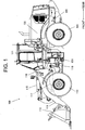
- FIG. 1 is a side view of a wheel loader that is an example of an HST vehicle according to a first embodiment.
- a wheel loader 100 is formed of a front vehicle body 110, which includes an arm 111, a bucket 112, front wheels 113, and other components, and a rear vehicle body 120, which includes a cab 121, a machine room 122, rear wheels 123, and other components.
- the arm 111 is driven by an arm cylinder 117 so as to pivot upward and downward (rise and lower), and the bucket 112 is driven by a bucket cylinder 115 so as to pivot upward and downward (crowd and dump).
- the front vehicle body 110 and the rear vehicle body 120 are pivotally linked to each other via a center pin 101, and the front vehicle body 110 bends rightward and leftward relative to the rear vehicle body 120 when a steering cylinder 116 extends and contracts.
- the cab 121 includes an accelerator pedal 6, an accelerator pedal operation amount detector 6a, a forward/rearward changeover switch 16, an HST pump characteristic changing switch 20, and an engine key switch that is not shown, each of which will be described later. It is noted that the HST pump characteristic changing switch 20 is kept turned on in the first embodiment.
- the machine room 122 accommodates an engine 1, which will be described later.
- FIG. 2 shows a schematic configuration of the wheel loader according to the first embodiment.
- the wheel loader includes what is called an HST travel driver (travel system) and includes a hydraulic pump 2, which is driven by the engine 1, and a hydraulic motor 3, which is connected to the hydraulic pump 2 in the form of a closed circuit, as shown in Figure 2 .
- HST travel driver travel system
- the wheel loader 100 thus travels.
- the rotational speed of the engine 1 is controlled by an engine controller 1a.
- the "rotational speed” is a physical quantity representing the number of rotations per unit time.
- the drive force produced by the engine 1 is transmitted to the hydraulic pump 2, an HST charge pump 9, and a fixed-volume hydraulic pump (hereinafter referred to as work pump 10) .
- the engine controller 1a is a microcomputer including a CPU, a ROM, and a RAM and controls the rotational speed of the engine 1 based on outputs outputted from a variety of sensors and received via a vehicle controller 8.
- the hydraulic pump 2 is a swash-plate-type or bent-axis-type variable-displacement hydraulic pump, in which the displaced volume (hereinafter referred to as pump volume) qp is changed in accordance with the tilting angle.
- the pump volume qp of the hydraulic pump 2 is controlled by a pump regulator 182, which operates based on the output from the vehicle controller 8 and independently of the engine rotational speed.
- the hydraulic motor 3 is a swash-plate-type or bent-axis-type variable-displacement hydraulic motor, in which the displaced volume (hereinafter referred to as motor volume) is changed in accordance with the tilting angle.
- the motor volume of the hydraulic motor 3 is controlled by a motor regulator 183, which operates based on the output from the vehicle controller 8 and independently of the engine rotational speed.
- the configuration and operation of the motor regulator 182 are the same as those of the pump regulator 182, and the action of the pump regulator 182 will therefore be representatively described below.
- the motor volume is fixed at a constant value.
- FIG 3 shows the configuration of the pump regulator 182 in Figure 2 .
- the pump regulator 182 includes a tilting cylinder 30, a forward/rearward changeover valve 31, which changes its state in accordance with operation of the forward/rearward changeover switch 16, and a proportional solenoid pressure reducing valve (hereinafter referred to as proportional solenoid valve 32) that adjusts control pressure in accordance with a control signal from the vehicle controller 8, as shown in Figure 3 .
- proportional solenoid valve 32 proportional solenoid pressure reducing valve
- the pressure of the hydraulic oil from the HST charge pump 9 driven by the engine 1 is reduced via the proportional solenoid valve 32 and supplied as the control pressure to the tilting cylinder 30 via the forward/rearward changeover valve 31.
- the discharge pressure (primary pressure) of the HST charge pump 9 is defined by a relief valve 9a to be a predetermined value.
- the control pressure is supplied to the tilting cylinder 30 via the forward/rearward changeover valve 31, so that the pump volume qp is controlled in accordance with the control pressure, and the action direction of the tilting cylinder 30 is controlled in accordance with the switching operation performed by the forward/rearward changeover valve 31, whereby the tilting direction of the hydraulic pump 2 is controlled.
- the forward/rearward changeover valve 31 changes its state in accordance with a control signal outputted from the vehicle controller 8 in accordance with the position of the forward/rearward changeover switch 16.
- the control pressure is supplied to the tilting cylinder 30 via the forward/rearward changeover valve 31, so that the action direction and action amount of the tilting cylinder 30 are controlled. As a result, the tilting direction and the pump volume qp of the hydraulic pump 2 are controlled.
- oil chambers 30a and 30b of the tilting cylinder 30 each have a tank pressure, so that a piston 30c is located in the neutral position.
- the pump volume qp of the hydraulic pump 2 is therefore zero, and the pump discharge flow rate is zero accordingly.
- the forward/rearward changeover valve 31 When the forward/rearward changeover switch 16 is switched to a forward (F) position, the forward/rearward changeover valve 31 is switched to the A side, so that the pressure of the hydraulic oil from the HST charge pump 9 is reduced by the proportional solenoid valve 32 and acts on the oil chamber 30a.
- the tank pressure acts on the oil chamber 30b.
- the difference in pressure between the oil chambers 30a and 30b of the tilting cylinder 30 is therefore produced, and the pressure difference displaces the piston 30c rightward in Figure 3 , so that the pump volume qp of the hydraulic pump 2 increases.
- the hydraulic pump 2 then rotates forward and discharges the hydraulic oil at a discharge flow rate according to the engine rotational speed and the pump volume qp.
- the forward/rearward changeover valve 31 When the forward/rearward changeover switch 16 is switched to a rearward (R) position, the forward/rearward changeover valve 31 is switched to the B side, so that the pressure of the hydraulic oil from the HST charge pump 9 is reduced by the proportional solenoid valve 32 and acts on the oil chamber 30b.
- the tank pressure acts on the oil chamber 30a.
- the difference in pressure between the oil chambers 30a and 30b of the tilting cylinder 30 is therefore produced, and the pressure difference displaces the piston 30c leftward in Figure 3 , so that the pump volume qp of the hydraulic pump 2 increases.
- the hydraulic pump 2 then rotates rearward and discharges the hydraulic oil at a discharge flow rate according to the engine rotational speed and the pump volume qp.
- the hydraulic motor 3 is a variable-displacement hydraulic motor.
- the volume of the hydraulic motor 3 (hereinafter referred to as motor volume) is controlled by the vehicle controller 8.
- the hydraulic motor 3 is drive by the hydraulic oil discharged from the hydraulic pump 2 connected to the hydraulic motor 3 via an HST circuit 15.
- a rotational speed sensor 7 detects the rotational speed of the engine 1 and outputs the result of the detection, for example, in the form of a current signal to the vehicle controller 8.
- the vehicle controller 8 includes a computation processor including a CPU, a ROM and a RAM, each of which is a storage device, and other peripheral circuits.
- the vehicle controller 8 is, so to speak, a portion that controls the wheel loader 100.
- the accelerator pedal operation amount detector 6a which detects a pedal operation amount by which the accelerator pedal 6 is operated (pedal stroke or pedal angle), and the rotational speed sensor 7 are connected to the vehicle controller 8, as shown in Figure 2 .
- the vehicle controller 8 outputs the pedal operation amount representing the amount of operation performed on the accelerator pedal 6 and detected with the accelerator pedal operation amount detector 6a to the engine controller 1a.
- the forward/rearward changeover switch 16 which instructs forward/rearward motion of the vehicle, is connected to the vehicle controller 8, and the vehicle controller 8 detects the position of the operated forward/rearward changeover switch 16 (forward (F) / neutral (N) / rearward (R)).
- the vehicle controller 8 outputs a control signal in accordance with the position of the operated forward/rearward changeover switch 16 to the forward/rearward changeover valve 31 shown in Figure 3 .
- the vehicle controller 8 is connected to the engine controller 1a, the hydraulic pump 2, the hydraulic motor 3, the accelerator pedal operation amount detector 6a, the rotational speed sensor 7, a pressure sensor 12, the forward/rearward changeover switch 16, a urea remaining quantity sensor 18, a urea quality sensor 19, and the HST pump characteristic changing switch 20 via signal lines.
- the vehicle controller 8 transmits signals themselves received from the accelerator pedal operation amount detector 6a, the urea remaining quantity sensor 18, and the urea quality sensor 19 or information contained in the signals to the engine controller 1a.
- the hydraulic oil discharged from the work pump 10 is supplied to the work actuator 14 via the control valve 13 and drives the actuator 14.
- the control valve 13 is operated via a control lever that is not shown and controls the flow of the hydraulic oil from the work pump 10 to the actuator 14.
- the arm cylinder 117 and the bucket cylinder 115 are collectively referred to as the actuator 14, and an arm control valve or a bucket control valve is collectively referred to as the control valve 13 for convenience.
- An exhaust gas purifying device 160 includes a processing apparatus (not shown) that uses, for example, a urea aqueous solution (hereinafter referred to as urea water) as a reducing agent to clean nitrogen oxides in the exhaust gas exhausted from the engine 1, a urea water tank 17, which stores the urea water supplied to the processing apparatus, the urea remaining quantity sensor 18, which detects the quantity of remaining urea water in the urea water tank 17, and the urea quality sensor 19.
- a processing apparatus not shown
- a processing apparatus that uses, for example, a urea aqueous solution (hereinafter referred to as urea water) as a reducing agent to clean nitrogen oxides in the exhaust gas exhausted from the engine 1
- a urea water tank 17 which stores the urea water supplied to the processing apparatus
- the urea remaining quantity sensor 18 which detects the quantity of remaining urea water in the urea water tank 17, and the urea quality sensor 19.
- the engine controller 1a sets a target engine rotational speed of the engine 1 and controls a fuel injector (not shown) to cause the actual rotational speed of the engine 1 to approach the set target engine rotational speed.
- the engine controller 1a has the following two action modes that affect the setting of the target engine rotational speed: a normal mode; and a restricted mode.
- the engine controller 1a determines the target engine rotational speed based on the pedal operation amount received from the vehicle controller 8.
- the engine controller 1a sets the target engine rotational speed of the engine 1 to be a low-idle speed irrespective of the pedal operation amount received from the vehicle controller 8. It is noted that the engine controller 1a gradually lowers the rotational speed of the engine 1 to prevent abrupt change in the engine rotational speed.
- the engine controller 1a switches the action mode that is the normal mode when the engine starts operating between the normal mode and the restricted mode based on the outputs outputted from the urea remaining quantity sensor 18 and the urea quality sensor 19 and received from the engine controller 1a. That is, the engine controller 1a switches the action mode to the restricted mode when the quantity of the remaining urea water is smaller than a predetermined threshold or the quality of the urea water is lower than a predetermined threshold. On the other hand, the engine controller 1a switches the action mode to the normal mode when the quantity of the remaining urea water becomes greater than the predetermined threshold due, for example, to addition of urea water to the urea water tank 17 and the quality of the urea water becomes higher than the predetermined threshold.
- the engine controller 1a does not output information on the change in the action mode or information on the current action mode to the vehicle controller 8.
- the state in which the urea water has high quality is a state in which the quality of the urea water falls within a predetermined range or a state in which the urea water has a small amount of impurities.
- Figure 4 shows the relationship between the pedal operation amount received from the vehicle controller 8 and the target engine rotational speed in the normal mode and the restricted mode.
- the solid line represents the characteristic of the relationship in the normal mode
- the broken line represents the characteristic of the relationship in the restricted mode. It is noted in Figure 4 that the pedal operation amount of 0% represents the minimum value thereof received from the vehicle controller 8, and that the pedal operation amount of 100% is the maximum value thereof received from the vehicle controller 8.
- the target engine rotational speed is set at a low-idle speed Ny in the case where the pedal operation amount is 0%, and the target engine rotational speed increases as the pedal operation amount increases.
- the target engine rotational speed is set at a high-idle speed Nx.
- the target engine rotational speed is fixed to the low-idle speed Ny irrespective of the magnitude of the pedal operation amount.
- the vehicle controller 8 has two action modes, the normal mode and the restricted mode.
- the vehicle controller 8 changes the method for determining the pump volume qp of the hydraulic pump 2 in accordance with the action mode.
- the vehicle controller 8 determines the pump volume qp based on the rotational speed of the engine 1 in the normal mode, whereas the pump volume qp is constant in the restricted mode.
- the vehicle controller 8 estimates the action mode of the engine controller 1a based on the outputs outputted from the accelerator pedal operation amount detector 6a and the rotational speed sensor 7 and the outputs outputted from the urea remaining quantity sensor 18 and the urea quality sensor 19 and received from the engine controller 1a and changes the action mode of the vehicle controller 8 to the action mode of the engine controller 1a.
- the vehicle controller 8 uses the pedal operation amount received from the accelerator pedal operation amount detector 6a to carry out processes described later and transmits the received pedal operation amount to the engine controller 1a.
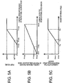
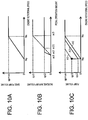
- Figure 5 shows a change in the pump volume qp of the hydraulic pump 2 in the normal mode.
- Figure 5A shows the relationship between the control pressure determined based on the output from the vehicle controller 8 and provided by the proportional solenoid valve 32 (hereinafter referred to as pump volume control pressure) and the pump volume qp of the hydraulic pump 2.
- Figure 5B shows the relationship between the current outputted by the rotational speed sensor 7 and the pump volume control pressure.
- Figure 5C shows the relationship between the rotational speed of the engine 1 and the current outputted by the rotational speed sensor 7 to the vehicle controller 8.
- the current outputted from the rotational speed sensor 7 has a minimum value lmin, for example, 4 mA, as shown in Figure 5C .
- the output current increases as the engine rotational speed increases to values greater than or equal to the low-idle speed Ny, and in a case where the engine rotational speed is higher than or equal to the high-idle speed Nx, the current outputted from the rotational speed sensor 7 has a maximum value lmax, for example, a constant value of 20 mA.
- the tendency of increase/decrease in the current outputted from the rotational speed sensor 7 coincides with the tendency of increase/decrease in the pump volume control pressure; when the current outputted from the rotational speed sensor 7 has the minimum value lmin, the pump volume control pressure is Pmin, and when the current outputted from the rotational speed sensor 7 has the maximum value lmax, the pump volume control pressure is Pmax, as shown in Figure 5B .
- the pump volume qp of the hydraulic pump 2 is zero, as shown in Figure 5A .
- the pump volume qp of the hydraulic pump 2 increases as the pump volume control pressure increases to values greater than or equal to Pmin, and in a case where the pump volume control pressure is higher than or equal to Pmax, the pump volume qp of the hydraulic pump 2 has a constant value qpmax.
- the control pressure provided by the proportional solenoid valve 32 and corresponding to the pump volume qp'min is P'min.
- the current outputted from the rotational speed sensor 7 and corresponding to the control pressure P'min provided by the proportional solenoid valve 32 is I'min.
- the engine rotational speed corresponding to the current I'min outputted from the rotational speed sensor 7 is N'y.
- Figure 6 compares the characteristic of the pump volume of the hydraulic pump 2 between the restricted mode and the normal mode.
- Figure 6A shows the relationship between the engine rotational speed and the pump volume qp of the hydraulic pump 2.
- Figure 6B shows the relationship between the engine rotational speed and the torque inputted to the hydraulic pump 2.
- Figure 6C shows the relationship between the engine rotational speed and the discharge flow rate of the hydraulic oil from the hydraulic pump 2.
- characteristics A0, H0, and R0 drawn with solid lines represent the characteristics of the relationships in the normal mode
- characteristics A1, H1, and R1 drawn with broken lines represent the characteristics of the relationships in the restricted mode.
- the characteristic A0 drawn with the solid line in Figure 6A represents the characteristics in the normal mode shown in Figures 5A to 5C but organized into the relationship between the engine rotational speed and the pump volume qp of the hydraulic pump 2.
- the characteristic A1 drawn with the broken line in the restricted mode shows that the pump volume qp of the hydraulic pump 2 has a constant value qp1 in the case where the engine rotational speed is higher than or equal to the low-idle speed Ny. It is noted that qp1 is greater than or equal to qp'min, which is the minimum pump volume that allows self-travel of the wheel loader 100.
- the torque inputted to the hydraulic pump 2 is also controlled in the same manner in which the displaced volume of the hydraulic pump 2 is controlled, as shown in Figure 6B . That is, the characteristic H0 drawn with the solid line in the normal mode shows that the input torque is zero in the case where the engine rotational speed is lower than the low-idle speed Ny, that the input torque increases as the engine rotational speed increases in the case where the engine rotational speed is higher than or equal to the low-idle speed Ny, and that the input torque has a constant value Tmax in the case where the engine rotational speed is higher than or equal to the high-idle speed Nx.
- the characteristic H1 drawn with the broken line in the restricted mode shows that the input torque is zero in the case where the engine rotational speed is lower than the low-idle speed Ny, and that the input torque has a constant value T1 in the case where the engine rotational speed is higher than or equal to the low-idle speed Ny.
- Figure 6C shows the characteristic of the discharge flow rate of the hydraulic oil from the hydraulic pump 2.
- the characteristic R0 drawn with the solid-line in the normal mode shows that the pump displaced volume is zero in the case where the engine rotational speed is lower than the low-idle speed Ny and the discharge flow rate is therefore also zero.
- the pump displaced volume increases as the engine rotational speed increases, and the discharge flow rate increases in a quadric manner.
- the discharge flow rate of the hydraulic oil from the pump linearly increases because the pump displaced volume does not increase any more.
- the characteristic R1 drawn with the broken line in the restricted mode shows that the pump displaced volume is zero in the case where the engine rotational speed is lower than the low-idle speed Ny and the discharge flow rate is therefore also zero.
- the discharge flow rate linearly increases as the engine rotational speed increases because the pump displaced volume is constant.
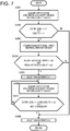
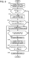
- FIG. 7 is a flowchart showing the action of a program that determines the action mode of the vehicle controller 8. Each step described below is actually carried out by the CPU in the vehicle controller 8.
- step S201 the CPU receives signals from the urea remaining quantity sensor 18 and the urea quality sensor 19, and in the subsequent step S202, the CPU evaluates whether or not the signals received in step S201 each satisfy a predetermined condition.
- the CPU determines that the urea water level outputted by the urea remaining quantity sensor 18 is lower than a predetermined threshold h1 or the urea water quality s outputted by the urea quality sensor 19 is lower than a predetermined threshold s1, the CPU proceeds to step S203.
- step S208 the CPU evaluates the possibility of whether the engine controller 1a is operating in the restricted mode, and when the CPU determines it is possible that the engine controller 1a is operating in the restricted mode, the CPU proceeds to step S203, whereas when the CPU determines it is not possible that the engine controller 1a is operating in the restricted mode, the CPU proceeds to step S208.
- step S203 the CPU receives signals from the accelerator pedal operation amount detector 6a and the rotational speed sensor 7, and in the subsequent step S204, the CPU evaluates whether or not the signals received in step S203 each satisfy a predetermined condition. In a case where the CPU determines that the engine rotational speed outputted by the rotational speed sensor 7 is lower than a predetermined rotational speed N1 and the pedal operation amount outputted by the accelerator pedal operation amount detector 6a is greater than a predetermined threshold (opening) ac1, the CPU proceeds to step S205.
- step S204 the CPU estimates whether or not the engine controller 1a is operating in the restricted mode, and when the CPU estimates that the engine controller 1a is operating in the restricted mode, the CPU proceeds to step S205, whereas when the CPU does not estimate that the engine controller 1a is operating in the restricted mode, the CPU proceeds to step S208.
- step S205 the CPU switches the action mode of the vehicle controller 8 to the restricted mode, selects the characteristic A1 as the characteristic of the pump displaced volume, and proceeds to step S206.
- step S206 the CPU receives signals from the urea remaining quantity sensor 18 and the urea quality sensor 19, as in step S201, and proceeds to step S207.
- step S207 the CPU evaluates whether or not the signals received in step S206 each satisfy a predetermined condition. In a case where the CPU determines that the urea water level h outputted by the urea remaining quantity sensor 18 is greater than a predetermined threshold h2 and the urea water quality s outputted by the urea quality sensor 19 is greater than a predetermined threshold s2 or the engine key switch is turned off, the CPU proceeds to step S208.
- the CPU determines that the urea water level outputted by the urea remaining quantity sensor 18 is smaller than or equal to the predetermined threshold h2 or the urea water quality outputted by the urea quality sensor 19 is smaller than or equal to the predetermined threshold s2 and the engine key switch that is not shown is maintained turned on, the CPU returns to step S206.
- step S207 the CPU evaluates whether or not a condition that allows the engine controller 1a to transition from the restricted mode to the normal mode is satisfied, and when the CPU determines that the condition that allows the engine controller 1a to transition to the normal mode is satisfied, the CPU proceeds to step S208, whereas when the CPU determines that the condition that allows the engine controller 1a to transition to the normal mode is not satisfied, the CPU returns to step S206.
- step S208 which is carried out when the CPU determines or estimates that the engine controller 1a is operating in the normal mode, the CPU switches the action mode of the vehicle controller 8 to the normal mode, selects the characteristic A0 as the characteristic of the pump displaced volume, and stops the action of the program shown in Figure 7 , which shows the action of the program.
- the engine controller 1a detects, for example, that the quantity of remaining urea water is smaller than a predetermined threshold and transitions to the restricted mode. In this state, even when an operator steps down the accelerator pedal 6, the engine rotational speed decreases to the low-idle speed Ny because the target engine rotational speed is fixed to the low-idle speed Ny.
- the vehicle controller 8 selects the characteristic A1.
- the pump volume has the constant value qp1, as shown in Figure 6 . Since qp1 is set to be greater than or equal to qp'min, which is the minimum pump volume of the hydraulic pump 2 controlled at the tilting angle associated with minimum travel drive force necessary for the self-travel of the wheel loader 100, as described above, the wheel loader 100 can travel by itself.
- the vehicle controller 8 temporarily selects the characteristic A1
- the characteristic A1 is maintained even when the operator stops stepping on the accelerator pedal 6 and the pedal operation amount therefore becomes zero. That is, the wheel loader 100 performs what is called creeping travel, which allows the wheel loader 100 to travel even when the operator does not step on the accelerator pedal 6.
- the wheel loader 100 cannot travel by itself because the engine controller 1a fixes the target engine rotational speed to the low-idle speed Ny.
- the wheel loader 100 includes the vehicle controller 8 having the configuration described above, the wheel loader 100 can travel by itself even when the engine controller 1a operates in the restricted mode. That is, the vehicle controller 8 increases the vehicle speed from zero to the speed in the creeping travel.
- the vehicle controller 8 sets the threshold N1 of the engine rotational speed for evaluating whether the engine controller 1a operates in the restricted state to at least be the engine rotational speed N'y corresponding to the pump volume qp that allows minimum power necessary for travel. Causing the vehicle controller 8 to transition to the restricted mode can therefore prevent the wheel loader 100 from stalling.
- the wheel loader 100 may be configured to travel only in a case where the accelerator pedal 6 is stepped down at least by a predetermined opening.
- Figure 8 is a flowchart showing the action of the action mode determining program in Variation 1. The same processes as those in Figure 7 in the first embodiment have the same step numbers and will not be described.
- Steps S201 to S204 are the same as those in the first embodiment and will not therefore be described.
- step S221 which is carried out when affirmative determination is made in step S204, the CPU reads the pedal operation amount of the accelerator pedal 6 in step S221 and proceeds to step S222.
- step S222 the CPU evaluates whether or not the pedal operation amount read in step S221 is greater than a predetermined threshold ac2. In a case where the CPU determines that the pedal operation amount is greater than the threshold ac2, the CPU proceeds to step S205, and in a case where the CPU determines that the pedal operation amount is smaller than or equal to the threshold ac2, the CPU proceeds to step S208.
- steps S205 to S208 are the same as those in the first embodiment and will not therefore be described. It is noted that in a case where negative determination is made in step S207, the CPU returns to step S221.
- the wheel loader 100 includes an input section to which the operator inputs a command of an increase in the rotational speed of the engine 1, that is, the input section corresponds to the accelerator pedal operation amount detector 6a.
- the vehicle controller 8 when it determines that the engine restrictor has restricted the rotational speed of the engine 1 and the command has been inputted to the accelerator pedal operation amount detector 6a, controls the HST circuit to increase the vehicle speed of the vehicle.
- the HST pump characteristic changing switch 20 is kept turned on.
- the HST pump characteristic changing switch 20 may instead be operable by the operator.
- the vehicle controller 8 further evaluates whether the HST pump characteristic changing switch 20 has been turned on as the condition that allows transition to the restricted mode in addition to the condition described in the first embodiment.
- Figure 9 is a flowchart showing the action of the action mode determining program in Variation 2.
- Steps S201 to S204 are the same as those in the first embodiment and will not therefore be described.
- step S241 which is carried out when affirmative determination is made in step S204, the CPU reads the set state of the HST pump characteristic changing switch 20 and proceeds to step S242.
- step S242 the CPU evaluates whether or not the state of the HST pump characteristic changing switch 20 read in step S241 has been turned on. In a case where the CPU determines that the HST pump characteristic changing switch 20 has been turned on, the CPU proceeds to step S205, and in a case where the CPU does not determine that the HST pump characteristic changing switch 20 has been turned on, the CPU proceeds to step S208.
- steps S205 to S208 are the same as those in the first embodiment and will not therefore be described. It is noted that in a case where negative determination is made in step S207, the CPU returns to step S241.
- the operator can operate the HST pump characteristic changing switch 20 to switch the action mode of the vehicle controller 8 between the state in which the restricted mode is activated and the state in which the restricted mode is deactivated.
- the engine controller 1a does not output information on the change in the action mode or information on the current action mode to the vehicle controller 8.
- the engine controller 1a may instead output information on the change in the action mode or information on the current action mode to the vehicle controller 8.
- the vehicle controller 8 since the vehicle controller 8 does not need to estimate the action mode of the engine controller 1a based on the output from the accelerator pedal operation amount detector 6a, the rotational speed sensor 7, the urea remaining quantity sensor 18, or the urea quality sensor 19, the processes carried out by the vehicle controller 8 are simplified. For example, in a case where the engine controller 1a outputs information on the current action mode to the vehicle controller 8, the vehicle controller 8 also changes the action mode thereof in accordance with the action mode outputted by the engine controller 1a.
- the action of the vehicle controller 8 can be simplified, and the change in the action mode of the engine controller 1a can be quickly sensed.
- the reducing agent used by the wheel loader 100 is not limited to the urea water and may instead be an ammonia aqueous solution or any other reducing agent.
- the HST circuit is formed of one hydraulic pump and one hydraulic motor and may instead be formed of a plurality of hydraulic pumps and/or a plurality of hydraulic motors. Further, instead of switching the volume characteristic of the hydraulic pump 2, the number of hydraulic pumps connected to the HST circuit may be changed.
- a second embodiment of a wheel loader that is an HST vehicle according to the present invention will be described with reference to Figures 10 and 11 .
- the same components as those in the first embodiment have the same reference characters, and points different from those in the first embodiment will be primarily described. Points that will not be particularly described are the same as those in the first embodiment.
- the present embodiment primarily differs from the first embodiment in that the pump displaced volume is increased in accordance with the pedal operation amount.
- the configuration of the wheel loader 100 differs from the configuration in the first embodiment in terms of the action of the program saved in the ROM of the vehicle controller 8.
- the vehicle controller 8 determines the pump volume qp of the hydraulic pump 2 based on the pedal operation amount received from the accelerator pedal operation amount detector 6a and the rotational speed of the engine 1 detected with the rotational speed sensor 7.
- the pump volume qp is expressed by the sum of a base volume qb, which is determined in accordance with the engine rotational speed, and an increased volume qd, which is determined in accordance with the pedal operation amount. It is noted that the upper limit of the pump volume qp is qpmax, as in the first embodiment.
- Figure 10 shows the relationship among the pedal operation amount, the engine rotational speed, and the pump volume qp.
- Figure 10A shows the relationship between the engine rotational speed and the base volume qb.
- Figure 10B shows the relationship between the pedal operation amount and the increased volume qd.
- Figure 10C shows the relationship between the engine rotational speed and the pump volume qp.
- the base volume qb is determined by the engine rotational speed irrespective of the action mode of the vehicle controller 8, as shown in Figure 10A .
- the base volume qb is zero in the case where the engine rotational speed is lower than the low-idle speed Ny.
- the base volume qb linearly increases as the engine rotational speed increases to values higher than or equal to the low-idle speed Ny, and the base volume qb has the maximum constant value qpmax when the engine rotational speed is higher than or equal to the high-idle speed Nx.
- the increased volume qd is determined by the action mode of the vehicle controller 8 and the pedal operation amount, as shown in Figure 10B .
- the solid line represents the characteristic of the increased volume qd in the normal mode
- the broken line represents the characteristic of the increased volume qd in the restricted mode.
- the increased volume qd is zero in a case where the pedal operation amount is smaller than ac1, linearly increases in a case where the pedal operation amount is greater than or equal to ac1 but smaller than ac2, and has a constant value qp2 in a case where the pedal operation amount is greater than or equal to ac2.
- the increased volume qd is zero in the case where the pedal operation amount is smaller than ac1, linearly increases in a case where the pedal operation amount is greater than or equal to ac1 but smaller than ac3, and has a constant value qp3 in a case where the pedal operation amount is greater than or equal to ac3.
- the increased volume qd is qb2 in a case where the pedal operation amount is ac21.
- the pedal operation amount ac3 is greater than the pedal operation amount ac2, and qp3, which is the increased volume qd, is greater than qp2. It is noted that the ratio of the increase in the increased volume qd to the increase in the pedal operation amount is smaller in the restricted mode than in the normal mode.
- Figure 10C shows a representative characteristic of the pump volume qp, which is the sum of the base volume qb and the increased volume qd.
- the characteristic A0 is the characteristic in the case where the pedal operation amount is zero irrespective of the action mode. Since the increased volume qd is zero, the pump volume qp is zero in the case where the engine rotational speed is the low-idle speed Ny.
- a characteristic A2 is the characteristic in the case where the pedal operation amount is greater than or equal to ac2 in the normal mode or in the case where the pedal operation amount is ac21 in the restricted mode. Since the increased volume qd is qb2, the pump volume qp is qp2 even in the case where the engine rotational speed is the low-idle speed Ny.
- FIG. 10C shows only the three characteristic, but there are characteristics that continuously change in accordance with the pedal operation amount. That is, in the normal mode, one of the characteristics that fall within the range from A0 to A2 in Figure 10C is set, and in the restricted mode, one of the characteristics that fall within the range from A0 to A3 in Figure 10C is set.
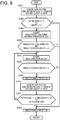
- FIG 11 is a flowchart showing the action of the vehicle controller 8 in the second embodiment.
- the same processes as those in Figure 7 in the first embodiment have the same step numbers and will not be described.
- Steps S201 to S204 are the same as those in the first embodiment and will not be therefore described.
- step S230 which is carried out when affirmative determination is made in step S204, the CPU reads the pedal operation amount of the accelerator pedal 6 in step S221 and proceeds to step S231.
- step S231 the CPU switches the action mode of the vehicle controller 8 to the restricted mode and determines the characteristic of the pump volume qp based on the pedal operation amount in such a way that the determined characteristic falls within the range from A0 to A3.
- steps S206 and S207 are then carried out.
- step S207 in the case where affirmative determination is made, the CPU proceeds to step S232, whereas in the case where negative determination is made, the CPU returns to step S230.
- the CPU reads the pedal operation amount of the accelerator pedal 6 in step S232 and proceeds to step S233.
- a third embodiment of a wheel loader that is an HST vehicle according to the present invention will be described with reference to Figure 12 .
- the same components as those in the first embodiment have the same reference characters, and points different from those in the first embodiment will be primarily described. Points that will not be particularly described are the same as those in the first embodiment.
- the present embodiment primarily differs from the first embodiment in that the volume of the hydraulic motor 3 is also changed in addition to the volume of the hydraulic pump 2.
- the configuration of the wheel loader 100 differs from the configuration in the first embodiment in terms of the action of the program saved in the ROM of the vehicle controller 8.
- the vehicle controller 8 decreases the motor volume of the hydraulic motor 3 in the restricted mode in addition to the action in the first embodiment.
- the motor volume is set at Mqp0
- the motor volume is set at Mqp, which is smaller than Mqp0.
- Figure 12 shows the time-series behavior of the wheel loader 100 in the case where the engine controller 1a transitions to the restricted mode during travel.
- Figure 12 shows, from above to below, how the engine rotational speed, the pump volume, the motor volume, and the vehicle speed change with time. It is noted that the pedal operation amount is always greater than the predetermined threshold ac1.
- the engine controller 1a starts lowering the target rotational speed of the engine 1 toward the low-idle speed Ny.
- the vehicle controller 8 maintains the normal mode because the engine rotational speed is greater than N1.
- the target rotational speed of the engine 1 keeps lowering toward the low-idle speed Ny, but the vehicle controller 8 maintains the normal mode because the engine rotational speed is still greater than N1 (NO in step S204 and transition to step S208 in Figure 7 ).
- the vehicle controller 8 transitions to the restricted mode because the engine rotational speed is lower than N1 and the pedal operation amount is greater than the threshold ac1 (YES in step S204 and transition to step S205 in Figure 7 ).
- the engine rotational speed N1 is the speed corresponding to the pump volume qp'min
- the pump volume after the time T1 has the constant value qp'min, as shown in Figure 12 .
- the motor volume is set at Mqp', which is smaller than Mqp0 in the normal mode, the motor volume starts decreasing.
- the following advantageous effect is provided in addition to the effects in the first embodiment.
- the vehicle controller 8 when it determines that the engine controller 1a operates in the restricted mode, increases the volume of the HST pump (hydraulic pump) 2 but decreases the volume of the HST motor, and the vehicle speed of the wheel loader 100 can therefore be further increased, as compared with the vehicle speed in the first embodiment, in which the volume of the HST motor is not decreased.
- the vehicle controller 8 controls both the pump volume of the hydraulic pump 2 and the motor volume of the hydraulic motor 3 in the restricted mode differently from the control in the normal mode.
- the vehicle controller 8 may instead control only the motor volume of the hydraulic motor 3 in the restricted mode differently from the control in the normal mode. That is, the vehicle controller 8 determines the pump volume of the hydraulic pump 2 based on the engine rotational speed in the restricted mode as in the normal mode but decreases the motor volume of the hydraulic motor 3 in such a way that the wheel loader 100 can travel by itself.
Landscapes
- Engineering & Computer Science (AREA)
- Chemical & Material Sciences (AREA)
- Combustion & Propulsion (AREA)
- Mechanical Engineering (AREA)
- Transportation (AREA)
- General Engineering & Computer Science (AREA)
- Mining & Mineral Resources (AREA)
- Civil Engineering (AREA)
- Structural Engineering (AREA)
- Control Of Vehicle Engines Or Engines For Specific Uses (AREA)
- Operation Control Of Excavators (AREA)
- Motor Power Transmission Devices (AREA)
- Control Of Driving Devices And Active Controlling Of Vehicle (AREA)
- Exhaust Gas After Treatment (AREA)
Description
- The present invention relates to a work vehicle.
- A work vehicle represented by an HST (hydro static transmission) vehicle includes a reducing device in which a reducing agent cleans exhaust gas exhausted from an engine. There is a known configuration that starts restricting the engine rotational speed when the quantity of remaining reducing agent is smaller than or equal to a predetermined threshold and lowers the engine rotational speed to a low-idle speed to prevent high-power operation.
-
Patent Literature 1 discloses a configuration that prevents an engine from stalling when the work vehicle starts restricting the engine rotational speed. - Patent Literature 1: Japanese Patent Laid-Open No.
2015-71976 - In the invention described in
Patent Literature 1, there is no description of a case where the engine rotational speed is restricted to a low-idle speed. Therefore, in a case where an HST pump is set to start discharging the hydraulic oil when the engine rotational speed is higher than the low-idle speed, it is not clear that the HST vehicle can travel by itself. - For example, in the case where the HST pump is set to start discharging the hydraulic oil when the engine rotational speed is higher than the low-idle speed, and when the engine rotational speed is restricted to the low engine rotational speed, the HST pump does not discharge the hydraulic oil, and the work vehicle therefore cannot travel by itself.
EP 2857591 A1 discloses a work vehicle in which a hydraulic pump is driven by an engine. A remaining amount detection device detects a remaining amount of a reducing agent solution in the reducing agent tank. A torque control unit decreases output torque of the engine according to decrease of the detected remaining amount of the reducing agent solution. When the actual rotational speed of the engine is not more than a threshold value, the torque control unit does not decrease the output torque of the engine regardless of the detected remaining amount of the reducing agent solution. -
EP 21289498 A1 pump control unit 31 that includes a pump correction command value calculating unit that sets a pump command value by determining an inching rate in accordance with the amount of operation when an inching operation is performed and corrects the pump reference command value. - It is the object of the invention to provide a work vehicle capable of travelling by itself even in the state in which the engine rotational speed is restricted.
- This object is accomplished by the features of
claim 1. - A work vehicle includes the features of
claim 1, amongst them an engine, a hydraulic pump driven by the engine, a hydraulic motor driven with hydraulic oil discharged from the hydraulic pump to drive wheels, an HST circuit in which the hydraulic pump and the hydraulic motor are connected to each other in a form of a closed circuit, a reducing agent sensor that detects a state of a reducing agent used to clean exhaust gas from the engine, and an engine restrictor that restricts a rotational speed of the engine based on an output from the reducing agent sensor, and the work vehicle further includes a control unit that changes a tilting angle of the hydraulic pump or the hydraulic motor independently of the rotational speed of the engine to the tilting angle associated with minimum travel drive force necessary for self-travel of the work vehicle when the control unit determines that the engine restrictor has restricted the rotational speed of the engine.Claim 1 recites further features. - According to the present invention, an HST vehicle is allowed to travel by itself even in the state in which the engine rotational speed is restricted.
-
- [
Figure 1] Figure 1 is a side view of awheel loader 100. - [
Figure 2] Figure 2 shows a schematic configuration of thewheel loader 100. - [
Figure 3] Figure 3 shows the configuration of apump regulator 182. - [
Figure 4] Figure 4 shows the relationship between a pedal operation amount received from avehicle controller 8 and a target engine rotational speed in a normal mode and a restricted mode. - [
Figure 5] Figure 5A shows the relationship between pump volume control pressure and a pump volume qp of ahydraulic pump 2,Figure 5B shows the relationship between current outputted by arotational speed sensor 7 and pump volume control pressure, andFigure 5C shows the relationship between the rotational speed of anengine 1 and the current outputted by therotational speed sensor 7. - [
Figure 6] Figure 6 compares the characteristic of the pump volume of thehydraulic pump 2 between the restricted mode and the normal mode. - [
Figure 7] Figure 7 is a flowchart showing the action of an action mode determining program. - [
Figure 8] Figure 8 is a flowchart showing the action of the action mode determining program inVariation 1. - [
Figure 9] Figure 9 is a flowchart showing the action of the action mode determining program inVariation 2. - [
Figure 10] Figure 10 shows the relationship among the pedal operation amount, the engine rotational speed, and the pump volume qp in a second embodiment. - [
Figure 11] Figure 11 is a flowchart showing the action of thevehicle controller 8 in the second embodiment. - [
Figure 12] Figure 12 shows an action example in a third embodiment. - A first embodiment of a wheel loader that is an HST vehicle according to the present invention will be described below with reference to
Figures 1 to 7 . -
Figure 1 is a side view of a wheel loader that is an example of an HST vehicle according to a first embodiment. Awheel loader 100 is formed of afront vehicle body 110, which includes anarm 111, abucket 112,front wheels 113, and other components, and arear vehicle body 120, which includes acab 121, amachine room 122,rear wheels 123, and other components. - The
arm 111 is driven by anarm cylinder 117 so as to pivot upward and downward (rise and lower), and thebucket 112 is driven by abucket cylinder 115 so as to pivot upward and downward (crowd and dump). Thefront vehicle body 110 and therear vehicle body 120 are pivotally linked to each other via acenter pin 101, and thefront vehicle body 110 bends rightward and leftward relative to therear vehicle body 120 when asteering cylinder 116 extends and contracts. - The
cab 121 includes an accelerator pedal 6, an accelerator pedaloperation amount detector 6a, a forward/rearward changeover switch 16, an HST pumpcharacteristic changing switch 20, and an engine key switch that is not shown, each of which will be described later. It is noted that the HST pumpcharacteristic changing switch 20 is kept turned on in the first embodiment. - The
machine room 122 accommodates anengine 1, which will be described later. -
Figure 2 shows a schematic configuration of the wheel loader according to the first embodiment. The wheel loader includes what is called an HST travel driver (travel system) and includes ahydraulic pump 2, which is driven by theengine 1, and ahydraulic motor 3, which is connected to thehydraulic pump 2 in the form of a closed circuit, as shown inFigure 2 . When hydraulic oil discharged from thehydraulic pump 2 rotates thehydraulic motor 3, the output torque from thehydraulic motor 3 is transmitted via a gear box that is not shown, an output shaft that is not shown, and an axle 4 and rotates thewheels wheel loader 100 thus travels. - The rotational speed of the
engine 1 is controlled by anengine controller 1a. In the present specification, the "rotational speed" is a physical quantity representing the number of rotations per unit time. The drive force produced by theengine 1 is transmitted to thehydraulic pump 2, anHST charge pump 9, and a fixed-volume hydraulic pump (hereinafter referred to as work pump 10) . - The
engine controller 1a is a microcomputer including a CPU, a ROM, and a RAM and controls the rotational speed of theengine 1 based on outputs outputted from a variety of sensors and received via avehicle controller 8. - The
hydraulic pump 2 is a swash-plate-type or bent-axis-type variable-displacement hydraulic pump, in which the displaced volume (hereinafter referred to as pump volume) qp is changed in accordance with the tilting angle. The pump volume qp of thehydraulic pump 2 is controlled by apump regulator 182, which operates based on the output from thevehicle controller 8 and independently of the engine rotational speed. - The
hydraulic motor 3 is a swash-plate-type or bent-axis-type variable-displacement hydraulic motor, in which the displaced volume (hereinafter referred to as motor volume) is changed in accordance with the tilting angle. The motor volume of thehydraulic motor 3 is controlled by amotor regulator 183, which operates based on the output from thevehicle controller 8 and independently of the engine rotational speed. The configuration and operation of themotor regulator 182 are the same as those of thepump regulator 182, and the action of thepump regulator 182 will therefore be representatively described below. In the first embodiment, the motor volume is fixed at a constant value. -
Figure 3 shows the configuration of thepump regulator 182 inFigure 2 . Thepump regulator 182 includes a tiltingcylinder 30, a forward/rearward changeover valve 31, which changes its state in accordance with operation of the forward/rearward changeover switch 16, and a proportional solenoid pressure reducing valve (hereinafter referred to as proportional solenoid valve 32) that adjusts control pressure in accordance with a control signal from thevehicle controller 8, as shown inFigure 3 . - The pressure of the hydraulic oil from the
HST charge pump 9 driven by theengine 1 is reduced via theproportional solenoid valve 32 and supplied as the control pressure to the tiltingcylinder 30 via the forward/rearward changeover valve 31. The discharge pressure (primary pressure) of theHST charge pump 9 is defined by arelief valve 9a to be a predetermined value. The control pressure is supplied to thetilting cylinder 30 via the forward/rearward changeover valve 31, so that the pump volume qp is controlled in accordance with the control pressure, and the action direction of the tiltingcylinder 30 is controlled in accordance with the switching operation performed by the forward/rearward changeover valve 31, whereby the tilting direction of thehydraulic pump 2 is controlled. - The forward/
rearward changeover valve 31 changes its state in accordance with a control signal outputted from thevehicle controller 8 in accordance with the position of the forward/rearward changeover switch 16. The control pressure is supplied to thetilting cylinder 30 via the forward/rearward changeover valve 31, so that the action direction and action amount of the tiltingcylinder 30 are controlled. As a result, the tilting direction and the pump volume qp of thehydraulic pump 2 are controlled. - When the forward/
rearward changeover switch 16 is switched to a neutral (N) position, oil chambers 30a and 30b of the tiltingcylinder 30 each have a tank pressure, so that a piston 30c is located in the neutral position. The pump volume qp of thehydraulic pump 2 is therefore zero, and the pump discharge flow rate is zero accordingly. - When the forward/
rearward changeover switch 16 is switched to a forward (F) position, the forward/rearward changeover valve 31 is switched to the A side, so that the pressure of the hydraulic oil from theHST charge pump 9 is reduced by theproportional solenoid valve 32 and acts on the oil chamber 30a. On the other hand, the tank pressure acts on the oil chamber 30b. The difference in pressure between the oil chambers 30a and 30b of the tiltingcylinder 30 is therefore produced, and the pressure difference displaces the piston 30c rightward inFigure 3 , so that the pump volume qp of thehydraulic pump 2 increases. Thehydraulic pump 2 then rotates forward and discharges the hydraulic oil at a discharge flow rate according to the engine rotational speed and the pump volume qp. - When the forward/
rearward changeover switch 16 is switched to a rearward (R) position, the forward/rearward changeover valve 31 is switched to the B side, so that the pressure of the hydraulic oil from theHST charge pump 9 is reduced by theproportional solenoid valve 32 and acts on the oil chamber 30b. On the other hand, the tank pressure acts on the oil chamber 30a. The difference in pressure between the oil chambers 30a and 30b of the tiltingcylinder 30 is therefore produced, and the pressure difference displaces the piston 30c leftward inFigure 3 , so that the pump volume qp of thehydraulic pump 2 increases. Thehydraulic pump 2 then rotates rearward and discharges the hydraulic oil at a discharge flow rate according to the engine rotational speed and the pump volume qp. - The description will be resumed with reference to
Figure 2 again. - The
hydraulic motor 3 is a variable-displacement hydraulic motor. The volume of the hydraulic motor 3 (hereinafter referred to as motor volume) is controlled by thevehicle controller 8. Thehydraulic motor 3 is drive by the hydraulic oil discharged from thehydraulic pump 2 connected to thehydraulic motor 3 via anHST circuit 15. - A
rotational speed sensor 7 detects the rotational speed of theengine 1 and outputs the result of the detection, for example, in the form of a current signal to thevehicle controller 8. - The
vehicle controller 8 includes a computation processor including a CPU, a ROM and a RAM, each of which is a storage device, and other peripheral circuits. Thevehicle controller 8 is, so to speak, a portion that controls thewheel loader 100. The accelerator pedaloperation amount detector 6a, which detects a pedal operation amount by which the accelerator pedal 6 is operated (pedal stroke or pedal angle), and therotational speed sensor 7 are connected to thevehicle controller 8, as shown inFigure 2 . - The
vehicle controller 8 outputs the pedal operation amount representing the amount of operation performed on the accelerator pedal 6 and detected with the accelerator pedaloperation amount detector 6a to theengine controller 1a. - The forward/
rearward changeover switch 16, which instructs forward/rearward motion of the vehicle, is connected to thevehicle controller 8, and thevehicle controller 8 detects the position of the operated forward/rearward changeover switch 16 (forward (F) / neutral (N) / rearward (R)). Thevehicle controller 8 outputs a control signal in accordance with the position of the operated forward/rearward changeover switch 16 to the forward/rearward changeover valve 31 shown inFigure 3 . - The
vehicle controller 8 is connected to theengine controller 1a, thehydraulic pump 2, thehydraulic motor 3, the accelerator pedaloperation amount detector 6a, therotational speed sensor 7, apressure sensor 12, the forward/rearward changeover switch 16, a urea remainingquantity sensor 18, aurea quality sensor 19, and the HST pump characteristic changingswitch 20 via signal lines. Thevehicle controller 8 transmits signals themselves received from the accelerator pedaloperation amount detector 6a, the urea remainingquantity sensor 18, and theurea quality sensor 19 or information contained in the signals to theengine controller 1a. - The
wheel loader 100 includes a front work apparatus (work system) including thework pump 10, acontrol valve 13, anactuator 14, the arm 111 (Figure 1 ), and the bucket 112 (Figure 1 ). Thework pump 10 is driven by theengine 1 and discharges hydraulic oil. - The hydraulic oil discharged from the
work pump 10 is supplied to thework actuator 14 via thecontrol valve 13 and drives theactuator 14. Thecontrol valve 13 is operated via a control lever that is not shown and controls the flow of the hydraulic oil from thework pump 10 to theactuator 14. InFigure 2 , thearm cylinder 117 and thebucket cylinder 115 are collectively referred to as theactuator 14, and an arm control valve or a bucket control valve is collectively referred to as thecontrol valve 13 for convenience. - An exhaust
gas purifying device 160 includes a processing apparatus (not shown) that uses, for example, a urea aqueous solution (hereinafter referred to as urea water) as a reducing agent to clean nitrogen oxides in the exhaust gas exhausted from theengine 1, aurea water tank 17, which stores the urea water supplied to the processing apparatus, the urea remainingquantity sensor 18, which detects the quantity of remaining urea water in theurea water tank 17, and theurea quality sensor 19. - The
engine controller 1a sets a target engine rotational speed of theengine 1 and controls a fuel injector (not shown) to cause the actual rotational speed of theengine 1 to approach the set target engine rotational speed. Theengine controller 1a has the following two action modes that affect the setting of the target engine rotational speed: a normal mode; and a restricted mode. - In the normal mode, the
engine controller 1a determines the target engine rotational speed based on the pedal operation amount received from thevehicle controller 8. In the restricted mode, theengine controller 1a sets the target engine rotational speed of theengine 1 to be a low-idle speed irrespective of the pedal operation amount received from thevehicle controller 8. It is noted that theengine controller 1a gradually lowers the rotational speed of theengine 1 to prevent abrupt change in the engine rotational speed. - The
engine controller 1a switches the action mode that is the normal mode when the engine starts operating between the normal mode and the restricted mode based on the outputs outputted from the urea remainingquantity sensor 18 and theurea quality sensor 19 and received from theengine controller 1a. That is, theengine controller 1a switches the action mode to the restricted mode when the quantity of the remaining urea water is smaller than a predetermined threshold or the quality of the urea water is lower than a predetermined threshold. On the other hand, theengine controller 1a switches the action mode to the normal mode when the quantity of the remaining urea water becomes greater than the predetermined threshold due, for example, to addition of urea water to theurea water tank 17 and the quality of the urea water becomes higher than the predetermined threshold. It is noted that theengine controller 1a does not output information on the change in the action mode or information on the current action mode to thevehicle controller 8. The state in which the urea water has high quality is a state in which the quality of the urea water falls within a predetermined range or a state in which the urea water has a small amount of impurities. -
Figure 4 shows the relationship between the pedal operation amount received from thevehicle controller 8 and the target engine rotational speed in the normal mode and the restricted mode. InFigure 4 , the solid line represents the characteristic of the relationship in the normal mode, and the broken line represents the characteristic of the relationship in the restricted mode. It is noted inFigure 4 that the pedal operation amount of 0% represents the minimum value thereof received from thevehicle controller 8, and that the pedal operation amount of 100% is the maximum value thereof received from thevehicle controller 8. - In the normal mode, the target engine rotational speed is set at a low-idle speed Ny in the case where the pedal operation amount is 0%, and the target engine rotational speed increases as the pedal operation amount increases. When the pedal operation amount reaches 100%, the target engine rotational speed is set at a high-idle speed Nx.
- In the restricted mode, the target engine rotational speed is fixed to the low-idle speed Ny irrespective of the magnitude of the pedal operation amount.
- The
vehicle controller 8 has two action modes, the normal mode and the restricted mode. Thevehicle controller 8 changes the method for determining the pump volume qp of thehydraulic pump 2 in accordance with the action mode. Thevehicle controller 8 determines the pump volume qp based on the rotational speed of theengine 1 in the normal mode, whereas the pump volume qp is constant in the restricted mode. - The
vehicle controller 8 estimates the action mode of theengine controller 1a based on the outputs outputted from the accelerator pedaloperation amount detector 6a and therotational speed sensor 7 and the outputs outputted from the urea remainingquantity sensor 18 and theurea quality sensor 19 and received from theengine controller 1a and changes the action mode of thevehicle controller 8 to the action mode of theengine controller 1a. - The
vehicle controller 8 uses the pedal operation amount received from the accelerator pedaloperation amount detector 6a to carry out processes described later and transmits the received pedal operation amount to theengine controller 1a. -
Figure 5 shows a change in the pump volume qp of thehydraulic pump 2 in the normal mode.Figure 5A shows the relationship between the control pressure determined based on the output from thevehicle controller 8 and provided by the proportional solenoid valve 32 (hereinafter referred to as pump volume control pressure) and the pump volume qp of thehydraulic pump 2.Figure 5B shows the relationship between the current outputted by therotational speed sensor 7 and the pump volume control pressure.Figure 5C shows the relationship between the rotational speed of theengine 1 and the current outputted by therotational speed sensor 7 to thevehicle controller 8. - In a case where the engine rotational speed is lower than the low-idle speed Ny, the current outputted from the
rotational speed sensor 7 has a minimum value lmin, for example, 4 mA, as shown inFigure 5C . The output current increases as the engine rotational speed increases to values greater than or equal to the low-idle speed Ny, and in a case where the engine rotational speed is higher than or equal to the high-idle speed Nx, the current outputted from therotational speed sensor 7 has a maximum value lmax, for example, a constant value of 20 mA. - The tendency of increase/decrease in the current outputted from the
rotational speed sensor 7 coincides with the tendency of increase/decrease in the pump volume control pressure; when the current outputted from therotational speed sensor 7 has the minimum value lmin, the pump volume control pressure is Pmin, and when the current outputted from therotational speed sensor 7 has the maximum value lmax, the pump volume control pressure is Pmax, as shown inFigure 5B . - In a case where the pump volume control pressure is lower than Pmin, the pump volume qp of the
hydraulic pump 2 is zero, as shown inFigure 5A . The pump volume qp of thehydraulic pump 2 increases as the pump volume control pressure increases to values greater than or equal to Pmin, and in a case where the pump volume control pressure is higher than or equal to Pmax, the pump volume qp of thehydraulic pump 2 has a constant value qpmax. To allow thewheel loader 100 to move, it is necessary to achieve at least a pump volume of qp'min of thehydraulic pump 2 controlled at a tilting angle associated with minimum travel drive force necessary for the self-travel of thewheel loader 100. The control pressure provided by theproportional solenoid valve 32 and corresponding to the pump volume qp'min is P'min. The current outputted from therotational speed sensor 7 and corresponding to the control pressure P'min provided by theproportional solenoid valve 32 is I'min. The engine rotational speed corresponding to the current I'min outputted from therotational speed sensor 7 is N'y. - The method for determining the pump volume qp of the
hydraulic pump 2 in the restricted mode will be described with reference toFigure 6 . -
Figure 6 compares the characteristic of the pump volume of thehydraulic pump 2 between the restricted mode and the normal mode.Figure 6A shows the relationship between the engine rotational speed and the pump volume qp of thehydraulic pump 2.Figure 6B shows the relationship between the engine rotational speed and the torque inputted to thehydraulic pump 2.Figure 6C shows the relationship between the engine rotational speed and the discharge flow rate of the hydraulic oil from thehydraulic pump 2. InFigures 6A to 6C , characteristics A0, H0, and R0 drawn with solid lines represent the characteristics of the relationships in the normal mode, and characteristics A1, H1, and R1 drawn with broken lines represent the characteristics of the relationships in the restricted mode. - The characteristic A0 drawn with the solid line in
Figure 6A represents the characteristics in the normal mode shown inFigures 5A to 5C but organized into the relationship between the engine rotational speed and the pump volume qp of thehydraulic pump 2. On the other hand, the characteristic A1 drawn with the broken line in the restricted mode shows that the pump volume qp of thehydraulic pump 2 has a constant value qp1 in the case where the engine rotational speed is higher than or equal to the low-idle speed Ny. It is noted that qp1 is greater than or equal to qp'min, which is the minimum pump volume that allows self-travel of thewheel loader 100. - The torque inputted to the
hydraulic pump 2 is also controlled in the same manner in which the displaced volume of thehydraulic pump 2 is controlled, as shown inFigure 6B . That is, the characteristic H0 drawn with the solid line in the normal mode shows that the input torque is zero in the case where the engine rotational speed is lower than the low-idle speed Ny, that the input torque increases as the engine rotational speed increases in the case where the engine rotational speed is higher than or equal to the low-idle speed Ny, and that the input torque has a constant value Tmax in the case where the engine rotational speed is higher than or equal to the high-idle speed Nx. The characteristic H1 drawn with the broken line in the restricted mode shows that the input torque is zero in the case where the engine rotational speed is lower than the low-idle speed Ny, and that the input torque has a constant value T1 in the case where the engine rotational speed is higher than or equal to the low-idle speed Ny. -
Figure 6C shows the characteristic of the discharge flow rate of the hydraulic oil from thehydraulic pump 2. The characteristic R0 drawn with the solid-line in the normal mode shows that the pump displaced volume is zero in the case where the engine rotational speed is lower than the low-idle speed Ny and the discharge flow rate is therefore also zero. In the area where the engine rotational speed is higher than or equal to the low-idle speed Ny but lower than the high-idle speed Nx, since the pump displaced volume increases as the engine rotational speed increases, and the discharge flow rate increases in a quadric manner. When the engine rotational speed becomes higher than or equal to the high-idle speed Nx, the discharge flow rate of the hydraulic oil from the pump linearly increases because the pump displaced volume does not increase any more. The characteristic R1 drawn with the broken line in the restricted mode shows that the pump displaced volume is zero in the case where the engine rotational speed is lower than the low-idle speed Ny and the discharge flow rate is therefore also zero. In the case where the engine rotational speed is higher than or equal to the low-idle speed Ny, the discharge flow rate linearly increases as the engine rotational speed increases because the pump displaced volume is constant. - The process of determining the action mode of the
vehicle controller 8 will be described with reference toFigure 7 . -
Figure 7 is a flowchart showing the action of a program that determines the action mode of thevehicle controller 8. Each step described below is actually carried out by the CPU in thevehicle controller 8. - In step S201, the CPU receives signals from the urea remaining
quantity sensor 18 and theurea quality sensor 19, and in the subsequent step S202, the CPU evaluates whether or not the signals received in step S201 each satisfy a predetermined condition. When the CPU determines that the urea water level outputted by the urea remainingquantity sensor 18 is lower than a predetermined threshold h1 or the urea water quality s outputted by theurea quality sensor 19 is lower than a predetermined threshold s1, the CPU proceeds to step S203. When the CPU determines that the urea water level outputted by the urea remainingquantity sensor 18 is higher than or equal to the predetermined threshold h1 and the urea water quality s outputted by theurea quality sensor 19 is higher than or equal to the predetermined threshold s1, the CPU proceeds to step S208. In step S202, the CPU evaluates the possibility of whether theengine controller 1a is operating in the restricted mode, and when the CPU determines it is possible that theengine controller 1a is operating in the restricted mode, the CPU proceeds to step S203, whereas when the CPU determines it is not possible that theengine controller 1a is operating in the restricted mode, the CPU proceeds to step S208. - In step S203, the CPU receives signals from the accelerator pedal
operation amount detector 6a and therotational speed sensor 7, and in the subsequent step S204, the CPU evaluates whether or not the signals received in step S203 each satisfy a predetermined condition. In a case where the CPU determines that the engine rotational speed outputted by therotational speed sensor 7 is lower than a predetermined rotational speed N1 and the pedal operation amount outputted by the accelerator pedaloperation amount detector 6a is greater than a predetermined threshold (opening) ac1, the CPU proceeds to step S205. In a case where the CPU determines that the engine rotational speed outputted by therotational speed sensor 7 is higher than or equal to the speed N1 or the pedal operation amount outputted by the accelerator pedaloperation amount detector 6a is smaller than or equal to the threshold ac1, the CPU proceeds to step S208. In step S204, the CPU estimates whether or not theengine controller 1a is operating in the restricted mode, and when the CPU estimates that theengine controller 1a is operating in the restricted mode, the CPU proceeds to step S205, whereas when the CPU does not estimate that theengine controller 1a is operating in the restricted mode, the CPU proceeds to step S208. - In step S205, the CPU switches the action mode of the
vehicle controller 8 to the restricted mode, selects the characteristic A1 as the characteristic of the pump displaced volume, and proceeds to step S206. - In step S206, the CPU receives signals from the urea remaining
quantity sensor 18 and theurea quality sensor 19, as in step S201, and proceeds to step S207. - In step S207, the CPU evaluates whether or not the signals received in step S206 each satisfy a predetermined condition. In a case where the CPU determines that the urea water level h outputted by the urea remaining
quantity sensor 18 is greater than a predetermined threshold h2 and the urea water quality s outputted by theurea quality sensor 19 is greater than a predetermined threshold s2 or the engine key switch is turned off, the CPU proceeds to step S208. In a case where the CPU determines that the urea water level outputted by the urea remainingquantity sensor 18 is smaller than or equal to the predetermined threshold h2 or the urea water quality outputted by theurea quality sensor 19 is smaller than or equal to the predetermined threshold s2 and the engine key switch that is not shown is maintained turned on, the CPU returns to step S206. In step S207, the CPU evaluates whether or not a condition that allows theengine controller 1a to transition from the restricted mode to the normal mode is satisfied, and when the CPU determines that the condition that allows theengine controller 1a to transition to the normal mode is satisfied, the CPU proceeds to step S208, whereas when the CPU determines that the condition that allows theengine controller 1a to transition to the normal mode is not satisfied, the CPU returns to step S206. - In step S208, which is carried out when the CPU determines or estimates that the
engine controller 1a is operating in the normal mode, the CPU switches the action mode of thevehicle controller 8 to the normal mode, selects the characteristic A0 as the characteristic of the pump displaced volume, and stops the action of the program shown inFigure 7 , which shows the action of the program. - When the quantity of remaining urea water decreases during travel of the
wheel loader 100, theengine controller 1a detects, for example, that the quantity of remaining urea water is smaller than a predetermined threshold and transitions to the restricted mode. In this state, even when an operator steps down the accelerator pedal 6, the engine rotational speed decreases to the low-idle speed Ny because the target engine rotational speed is fixed to the low-idle speed Ny. - When the operator keeps stepping on the accelerator pedal 6, the quantity of remaining urea water is small (YES in S202 in
Figure 7 ), and the relationship between the engine rotational speed and the pedal operation amount satisfies the predetermined condition (YES in S204 inFigure 7 ), so that thevehicle controller 8 selects the characteristic A1. In the case of the characteristic A1, the pump volume has the constant value qp1, as shown inFigure 6 . Since qp1 is set to be greater than or equal to qp'min, which is the minimum pump volume of thehydraulic pump 2 controlled at the tilting angle associated with minimum travel drive force necessary for the self-travel of thewheel loader 100, as described above, thewheel loader 100 can travel by itself. Further, when thevehicle controller 8 temporarily selects the characteristic A1, the characteristic A1 is maintained even when the operator stops stepping on the accelerator pedal 6 and the pedal operation amount therefore becomes zero. That is, thewheel loader 100 performs what is called creeping travel, which allows thewheel loader 100 to travel even when the operator does not step on the accelerator pedal 6. - If the aforementioned control is not performed by the
vehicle controller 8, thewheel loader 100 cannot travel by itself because theengine controller 1a fixes the target engine rotational speed to the low-idle speed Ny. However, since thewheel loader 100 includes thevehicle controller 8 having the configuration described above, thewheel loader 100 can travel by itself even when theengine controller 1a operates in the restricted mode. That is, thevehicle controller 8 increases the vehicle speed from zero to the speed in the creeping travel. - According to the first embodiment described above, the following advantageous effects are provided:
- (1) The
wheel loader 100 is an HST vehicle including theengine 1, theHST circuit 15, which includes thehydraulic pump 2, which is driven by theengine 1, and thehydraulic motor 3, which is driven with the hydraulic oil discharged from thehydraulic pump 2 to drive thewheels engine 1, that is, the urea remainingquantity sensor 18 and theurea quality sensor 19, and an engine restrictor that restricts the rotational speed of theengine 1, that is, the number of rotations of theengine 1 based on the output from the reducing agent sensor, that is, theengine controller 1a. Thewheel loader 100 further includes thevehicle controller 8, which controls the HST circuit to increase the vehicle speed of the vehicle when it is determined that the engine restrictor restricts the rotational speed of theengine 1, that is, the engine restrictor operates in the restricted mode.
The thus configuredwheel loader 100 can travel by itself even in the state in which the engine rotational speed is restricted. Therefore, even when theengine controller 1a fixes the target engine rotational speed to the low-idle speed, thewheel loader 100 can escape from a dangerous place, such as the middle of a roadway and a place inside a railroad crossing. - (2) The
vehicle controller 8, when it determines that the engine restrictor has restricted the rotational speed of theengine 1, increases the volume of thehydraulic pump 2.
Therefore, even in the state in which the rotational speed of theengine 1 is restricted, increasing the volume of thehydraulic pump 2 allows a large amount of energy to be extracted from theengine 1 for action of thewheel loader 100. - (3) The
vehicle controller 8, when it determines that the engine restrictor has restricted the rotational speed of theengine 1 during travel of the vehicle, controls the HST circuit to prevent the vehicle from stalling. - The
vehicle controller 8 sets the threshold N1 of the engine rotational speed for evaluating whether theengine controller 1a operates in the restricted state to at least be the engine rotational speed N'y corresponding to the pump volume qp that allows minimum power necessary for travel. Causing thevehicle controller 8 to transition to the restricted mode can therefore prevent thewheel loader 100 from stalling. - In the first embodiment described above, in the case where the
vehicle controller 8 operates in the restricted mode, what is called creeping travel, in which drive force for driving the vehicle is produced even when the operator does not step on the accelerator pedal 6, is performed. It is noted that also in the restricted mode, thewheel loader 100 may be configured to travel only in a case where the accelerator pedal 6 is stepped down at least by a predetermined opening. -
Figure 8 is a flowchart showing the action of the action mode determining program inVariation 1. The same processes as those inFigure 7 in the first embodiment have the same step numbers and will not be described. - Steps S201 to S204 are the same as those in the first embodiment and will not therefore be described. In step S221, which is carried out when affirmative determination is made in step S204, the CPU reads the pedal operation amount of the accelerator pedal 6 in step S221 and proceeds to step S222.
- In step S222, the CPU evaluates whether or not the pedal operation amount read in step S221 is greater than a predetermined threshold ac2. In a case where the CPU determines that the pedal operation amount is greater than the threshold ac2, the CPU proceeds to step S205, and in a case where the CPU determines that the pedal operation amount is smaller than or equal to the threshold ac2, the CPU proceeds to step S208.
- The processes in steps S205 to S208 are the same as those in the first embodiment and will not therefore be described. It is noted that in a case where negative determination is made in step S207, the CPU returns to step S221.
- According to
Variation 1, the following advantageous effect is provided:
(3) Thewheel loader 100 includes an input section to which the operator inputs a command of an increase in the rotational speed of theengine 1, that is, the input section corresponds to the accelerator pedaloperation amount detector 6a. Thevehicle controller 8, when it determines that the engine restrictor has restricted the rotational speed of theengine 1 and the command has been inputted to the accelerator pedaloperation amount detector 6a, controls the HST circuit to increase the vehicle speed of the vehicle. - Therefore, even when the
engine controller 1a operates in the restricted state, the operator can step on the accelerator pedal 6 to cause thewheel loader 100 to operate. - In the first embodiment described above, the HST pump characteristic changing
switch 20 is kept turned on. The HST pump characteristic changingswitch 20 may instead be operable by the operator. In this case, thevehicle controller 8 further evaluates whether the HST pump characteristic changingswitch 20 has been turned on as the condition that allows transition to the restricted mode in addition to the condition described in the first embodiment. -
Figure 9 is a flowchart showing the action of the action mode determining program inVariation 2. - Steps S201 to S204 are the same as those in the first embodiment and will not therefore be described. In step S241, which is carried out when affirmative determination is made in step S204, the CPU reads the set state of the HST pump characteristic changing
switch 20 and proceeds to step S242. - In step S242, the CPU evaluates whether or not the state of the HST pump characteristic changing
switch 20 read in step S241 has been turned on. In a case where the CPU determines that the HST pump characteristic changingswitch 20 has been turned on, the CPU proceeds to step S205, and in a case where the CPU does not determine that the HST pump characteristic changingswitch 20 has been turned on, the CPU proceeds to step S208. - The processes in steps S205 to S208 are the same as those in the first embodiment and will not therefore be described. It is noted that in a case where negative determination is made in step S207, the CPU returns to step S241.
- According to
Variation 2, the operator can operate the HST pump characteristic changingswitch 20 to switch the action mode of thevehicle controller 8 between the state in which the restricted mode is activated and the state in which the restricted mode is deactivated. - In the first embodiment described above, the
engine controller 1a does not output information on the change in the action mode or information on the current action mode to thevehicle controller 8. Theengine controller 1a may instead output information on the change in the action mode or information on the current action mode to thevehicle controller 8. - In this case, since the
vehicle controller 8 does not need to estimate the action mode of theengine controller 1a based on the output from the accelerator pedaloperation amount detector 6a, therotational speed sensor 7, the urea remainingquantity sensor 18, or theurea quality sensor 19, the processes carried out by thevehicle controller 8 are simplified. For example, in a case where theengine controller 1a outputs information on the current action mode to thevehicle controller 8, thevehicle controller 8 also changes the action mode thereof in accordance with the action mode outputted by theengine controller 1a. - According to
Variation 3, the action of thevehicle controller 8 can be simplified, and the change in the action mode of theengine controller 1a can be quickly sensed. - The reducing agent used by the
wheel loader 100 is not limited to the urea water and may instead be an ammonia aqueous solution or any other reducing agent. - In the first embodiment, the HST circuit is formed of one hydraulic pump and one hydraulic motor and may instead be formed of a plurality of hydraulic pumps and/or a plurality of hydraulic motors. Further, instead of switching the volume characteristic of the
hydraulic pump 2, the number of hydraulic pumps connected to the HST circuit may be changed. - A second embodiment of a wheel loader that is an HST vehicle according to the present invention will be described with reference to
Figures 10 and11 . In the following description, the same components as those in the first embodiment have the same reference characters, and points different from those in the first embodiment will be primarily described. Points that will not be particularly described are the same as those in the first embodiment. The present embodiment primarily differs from the first embodiment in that the pump displaced volume is increased in accordance with the pedal operation amount. - The configuration of the
wheel loader 100 differs from the configuration in the first embodiment in terms of the action of the program saved in the ROM of thevehicle controller 8. - The
vehicle controller 8 determines the pump volume qp of thehydraulic pump 2 based on the pedal operation amount received from the accelerator pedaloperation amount detector 6a and the rotational speed of theengine 1 detected with therotational speed sensor 7. In the second embodiment, the pump volume qp is expressed by the sum of a base volume qb, which is determined in accordance with the engine rotational speed, and an increased volume qd, which is determined in accordance with the pedal operation amount. It is noted that the upper limit of the pump volume qp is qpmax, as in the first embodiment. -
Figure 10 shows the relationship among the pedal operation amount, the engine rotational speed, and the pump volume qp.Figure 10A shows the relationship between the engine rotational speed and the base volume qb.Figure 10B shows the relationship between the pedal operation amount and the increased volume qd.Figure 10C shows the relationship between the engine rotational speed and the pump volume qp. - The base volume qb is determined by the engine rotational speed irrespective of the action mode of the
vehicle controller 8, as shown inFigure 10A . The base volume qb is zero in the case where the engine rotational speed is lower than the low-idle speed Ny. The base volume qb linearly increases as the engine rotational speed increases to values higher than or equal to the low-idle speed Ny, and the base volume qb has the maximum constant value qpmax when the engine rotational speed is higher than or equal to the high-idle speed Nx. - The increased volume qd is determined by the action mode of the
vehicle controller 8 and the pedal operation amount, as shown inFigure 10B . InFigure 10B , the solid line represents the characteristic of the increased volume qd in the normal mode, and the broken line represents the characteristic of the increased volume qd in the restricted mode. In the normal mode, the increased volume qd is zero in a case where the pedal operation amount is smaller than ac1, linearly increases in a case where the pedal operation amount is greater than or equal to ac1 but smaller than ac2, and has a constant value qp2 in a case where the pedal operation amount is greater than or equal to ac2. In the restricted mode, the increased volume qd is zero in the case where the pedal operation amount is smaller than ac1, linearly increases in a case where the pedal operation amount is greater than or equal to ac1 but smaller than ac3, and has a constant value qp3 in a case where the pedal operation amount is greater than or equal to ac3. In the restricted mode, the increased volume qd is qb2 in a case where the pedal operation amount is ac21. The pedal operation amount ac3 is greater than the pedal operation amount ac2, and qp3, which is the increased volume qd, is greater than qp2. It is noted that the ratio of the increase in the increased volume qd to the increase in the pedal operation amount is smaller in the restricted mode than in the normal mode. -
Figure 10C shows a representative characteristic of the pump volume qp, which is the sum of the base volume qb and the increased volume qd. The characteristic A0 is the characteristic in the case where the pedal operation amount is zero irrespective of the action mode. Since the increased volume qd is zero, the pump volume qp is zero in the case where the engine rotational speed is the low-idle speed Ny. A characteristic A2 is the characteristic in the case where the pedal operation amount is greater than or equal to ac2 in the normal mode or in the case where the pedal operation amount is ac21 in the restricted mode. Since the increased volume qd is qb2, the pump volume qp is qp2 even in the case where the engine rotational speed is the low-idle speed Ny. A characteristic A3 is the characteristic in the case where the pedal operation amount is greater than or equal to ac3 in the restricted mode. Since the increased volume qd is qp3, the pump volume qp is qp3 even in the case where the engine rotational speed is the low-idle speed Ny. - In the cases of characteristics A2 and A3, the pump volume qp reaches qpmax before the engine rotational speed reaches the high-idle speed Nx and does not increase any more even when the engine rotational speed further increases.
Figure 10C shows only the three characteristic, but there are characteristics that continuously change in accordance with the pedal operation amount. That is, in the normal mode, one of the characteristics that fall within the range from A0 to A2 inFigure 10C is set, and in the restricted mode, one of the characteristics that fall within the range from A0 to A3 inFigure 10C is set. -
Figure 11 is a flowchart showing the action of thevehicle controller 8 in the second embodiment. The same processes as those inFigure 7 in the first embodiment have the same step numbers and will not be described. - Steps S201 to S204 are the same as those in the first embodiment and will not be therefore described. In step S230, which is carried out when affirmative determination is made in step S204, the CPU reads the pedal operation amount of the accelerator pedal 6 in step S221 and proceeds to step S231.
- In step S231, the CPU switches the action mode of the
vehicle controller 8 to the restricted mode and determines the characteristic of the pump volume qp based on the pedal operation amount in such a way that the determined characteristic falls within the range from A0 to A3. To determine whether or not the restricted mode is maintained, steps S206 and S207 are then carried out. In step S207, in the case where affirmative determination is made, the CPU proceeds to step S232, whereas in the case where negative determination is made, the CPU returns to step S230. - The CPU reads the pedal operation amount of the accelerator pedal 6 in step S232 and proceeds to step S233.
- In step S233, the CPU switches the action mode of the
vehicle controller 8 to the normal mode, determines the characteristic of the pump volume qp based on the pedal operation amount in such a way that the determined characteristic falls within the range from A0 to A2, and stops the action of the program shown inFigure 11 , which shows the action of the program. - According to the second embodiment described above, since the pump volume qp is controlled in accordance with the pedal operation amount of the accelerator pedal 6 also in the restricted mode, fine adjustment of the vehicle speed can be performed.
- A third embodiment of a wheel loader that is an HST vehicle according to the present invention will be described with reference to
Figure 12 . In the following description, the same components as those in the first embodiment have the same reference characters, and points different from those in the first embodiment will be primarily described. Points that will not be particularly described are the same as those in the first embodiment. The present embodiment primarily differs from the first embodiment in that the volume of thehydraulic motor 3 is also changed in addition to the volume of thehydraulic pump 2. - The configuration of the
wheel loader 100 differs from the configuration in the first embodiment in terms of the action of the program saved in the ROM of thevehicle controller 8. - The
vehicle controller 8 decreases the motor volume of thehydraulic motor 3 in the restricted mode in addition to the action in the first embodiment. For example, in the normal mode, the motor volume is set at Mqp0, and in the restricted mode, the motor volume is set at Mqp, which is smaller than Mqp0. When the action described above is reflected in the flowchart ofFigure 7 in the first embodiment, the motor volume is set at Mqp' in step S205, and the motor volume is set at Mpq0 in step S208. - An action example in the third embodiment will be described with reference to
Figure 12 . -
Figure 12 shows the time-series behavior of thewheel loader 100 in the case where theengine controller 1a transitions to the restricted mode during travel.Figure 12 shows, from above to below, how the engine rotational speed, the pump volume, the motor volume, and the vehicle speed change with time. It is noted that the pedal operation amount is always greater than the predetermined threshold ac1. - At time T0, for example, the quantity of remaining urea water is smaller than a predetermined threshold, and the
engine controller 1a starts lowering the target rotational speed of theengine 1 toward the low-idle speed Ny. Thevehicle controller 8, however, maintains the normal mode because the engine rotational speed is greater than N1. - At time T'0, the target rotational speed of the
engine 1 keeps lowering toward the low-idle speed Ny, but thevehicle controller 8 maintains the normal mode because the engine rotational speed is still greater than N1 (NO in step S204 and transition to step S208 inFigure 7 ). - At time T1, the
vehicle controller 8 transitions to the restricted mode because the engine rotational speed is lower than N1 and the pedal operation amount is greater than the threshold ac1 (YES in step S204 and transition to step S205 inFigure 7 ). In a case where the engine rotational speed N1 is the speed corresponding to the pump volume qp'min, the pump volume after the time T1 has the constant value qp'min, as shown inFigure 12 . Further, since the motor volume is set at Mqp', which is smaller than Mqp0 in the normal mode, the motor volume starts decreasing. - At time T'1, the change in the motor volume to Mqp' is completed. Look now at the vehicle speed shown in the lowest portion of
Figure 12 , and the vehicle speed having decreased since the time T0 increases from the time T1 to the time T'1 because theengine controller 1a has transitioned to the restricted mode. The reason for this is that the pump volume is constant but the motor volume decreases. However, since the engine rotational speed keeps decreasing, the vehicle speed decreases after the time T'1. - Thereafter, the engine rotational speed reaches the low-idle speed Ny at time T2, and the vehicle speed becomes constant.
- According to the third embodiment, the following advantageous effect is provided in addition to the effects in the first embodiment.
- The
vehicle controller 8, when it determines that theengine controller 1a operates in the restricted mode, increases the volume of the HST pump (hydraulic pump) 2 but decreases the volume of the HST motor, and the vehicle speed of thewheel loader 100 can therefore be further increased, as compared with the vehicle speed in the first embodiment, in which the volume of the HST motor is not decreased. - In the third embodiment described above, the
vehicle controller 8 controls both the pump volume of thehydraulic pump 2 and the motor volume of thehydraulic motor 3 in the restricted mode differently from the control in the normal mode. Thevehicle controller 8 may instead control only the motor volume of thehydraulic motor 3 in the restricted mode differently from the control in the normal mode. That is, thevehicle controller 8 determines the pump volume of thehydraulic pump 2 based on the engine rotational speed in the restricted mode as in the normal mode but decreases the motor volume of thehydraulic motor 3 in such a way that thewheel loader 100 can travel by itself. - The embodiments and variations described above may be combined with each other.
- A variety of embodiments and variations have been described above, but the present invention is not limited to the contents thereof. Other aspect conceivable within the technical idea of the present invention falls within the scope of the present invention.
-
- 1
- Engine
- 1a
- Engine controller (engine restrictor)
- 2
- Hydraulic pump
- 3
- Hydraulic motor
- 6
- Accelerator pedal
- 6a
- Accelerator pedal operation amount detector
- 8
- Vehicle controller (control unit)
- 15
- HST circuit
- 18
- Urea remaining quantity sensor (reducing agent sensor)
- 19
- Urea quality sensor (reducing agent sensor)
- 20
- HST pump characteristic changing switch
- 100
- Wheel loader (work vehicle)
Claims (5)
- A work vehicle comprising:an engine (1);a rotational speed sensor (7) that detects a rotational speed of the engine (1);a hydraulic pump (2) driven by the engine (1), a hydraulic motor (3) driven with hydraulic oil discharged from the hydraulic pump (2) to drive wheels (113, 123), and an HST circuit (15) in which the hydraulic pump (2) and the hydraulic motor (3) are connected to each other in a form of a closed circuit;an accelerator pedal (6) and an accelerator pedal operation amount detector (6a) that detects a pedal operation amount by which the accelerator pedal (6) is operated;a reducing agent sensor (18, 19) that detects a state of a reducing agent used to clean exhaust gas from the engine (1) ;an engine controller (1a) that restricts the rotational speed of the engine (1) based on an output from the reducing agent sensor (18, 19); anda vehicle controller (8) that is connected to the reducing agent sensor (18, 19), the rotational speed sensor (7), and the accelerator pedal operation amount detector (6a) and controls the hydraulic pump (2) or the hydraulic motor (3),characterized in thatin a case where an output value from the reducing agent sensor (18, 19) does not satisfy a predetermined condition, the engine controller (1a) is configured to restrict the engine rotational speed to a low idle-speed, andin a state in which the engine rotational speed is restricted to a low idle-speed, the engine rotational speed outputted by the rotational speed sensor is lower than a predetermined speed, and the pedal operation amount outputted by the accelerator pedal operation amount detector (6a) is greater than a predetermined threshold, the vehicle controller (8) determines that the engine restrictor has restricted the rotational speed of the engine and changes a tilting angle of the hydraulic pump (2) or the hydraulic motor (3) independently of the rotational speed of the engine (1) to the tilting angle associated with minimum travel drive force necessary for self-travel of the work vehicle.
- The work vehicle according to claim 1, wherein
the hydraulic pump (2) includes a hydraulic pump regulator (182) that increases or decreases volume of the hydraulic pump (2), and
when the vehicle controller (8) determines that the engine controller (1a) has restricted the rotational speed of the engine (1), the vehicle controller (8) outputs a signal that increases a volume of the hydraulic pump (2) to the hydraulic pump regulator (182). - The work vehicle according to claim 1, wherein
the hydraulic motor (3) includes a hydraulic motor regulator (183) that increases or decreases volume of the hydraulic motor (1), and
when the vehicle controller (8) determines that the engine controller (1a) has restricted the rotational speed of the engine (1), the vehicle controller (8) outputs a signal that decreases a volume of the hydraulic motor (3) to the hydraulic motor regulator (183). - The work vehicle according to claim 1, wherein
the work vehicle further comprises an input section (6a) to which a command of an increase in the rotational speed of the engine (1) is inputted, and
when the vehicle controller (8) determines that the command greater than or equal to a predetermined value has been inputted to the input section (6a), the vehicle controller (8) changes the tilting angle to the tilting angle associated with minimum travel drive force necessary for self-travel of the work vehicle. - The work vehicle according to claim 1, wherein
in the case where the rotational speed of the engine (1) is restricted, the vehicle controller (8) maintains the tilting angle of the hydraulic pump (2) or the hydraulic motor (3) to be the tilting angle associated with minimum travel drive force necessary for self-travel of the work vehicle even when the pedal operation amount outputted by the accelerator pedal operation amount detector (6a) becomes zero.
Applications Claiming Priority (2)
| Application Number | Priority Date | Filing Date | Title |
|---|---|---|---|
| JP2016052722A JP6480368B2 (en) | 2016-03-16 | 2016-03-16 | Work vehicle |
| PCT/JP2017/004651 WO2017159133A1 (en) | 2016-03-16 | 2017-02-08 | Work vehicle |
Publications (3)
| Publication Number | Publication Date |
|---|---|
| EP3441272A1 EP3441272A1 (en) | 2019-02-13 |
| EP3441272A4 EP3441272A4 (en) | 2019-12-25 |
| EP3441272B1 true EP3441272B1 (en) | 2020-12-09 |
Family
ID=59850295
Family Applications (1)
| Application Number | Title | Priority Date | Filing Date |
|---|---|---|---|
| EP17766141.0A Active EP3441272B1 (en) | 2016-03-16 | 2017-02-08 | Work vehicle |
Country Status (6)
| Country | Link |
|---|---|
| US (1) | US10773590B2 (en) |
| EP (1) | EP3441272B1 (en) |
| JP (1) | JP6480368B2 (en) |
| KR (1) | KR101942852B1 (en) |
| CN (1) | CN107921957B (en) |
| WO (1) | WO2017159133A1 (en) |
Families Citing this family (8)
| Publication number | Priority date | Publication date | Assignee | Title |
|---|---|---|---|---|
| EP3660229B1 (en) * | 2018-09-28 | 2022-08-03 | Hitachi Construction Machinery Co., Ltd. | Loading vehicle |
| CN109774700B (en) * | 2018-11-15 | 2023-12-12 | 中国铁建重工集团股份有限公司 | Underground hydraulic driving traveling system and traveling speed adjusting method |
| US11286646B2 (en) * | 2019-03-13 | 2022-03-29 | Hitachi Construction Machinery Co., Ltd. | Loading vehicle |
| CH716216A1 (en) * | 2019-05-22 | 2020-11-30 | Liebherr Machines Bulle Sa | System for injecting a liquid into a pipe. |
| CN115151699B (en) * | 2020-09-23 | 2024-10-01 | 日立建机株式会社 | Work vehicles |
| WO2022201676A1 (en) * | 2021-03-26 | 2022-09-29 | 日立建機株式会社 | Work machine |
| KR102401511B1 (en) * | 2021-10-25 | 2022-05-25 | 주식회사 크린어스 | Start-up delay system with smoke reduction device |
| WO2024024990A1 (en) * | 2022-07-25 | 2024-02-01 | 주식회사 크린어스 | Start-up delay system having smoke reduction apparatus and start-up delay method using same |
Family Cites Families (10)
| Publication number | Priority date | Publication date | Assignee | Title |
|---|---|---|---|---|
| JP5156237B2 (en) * | 2007-01-24 | 2013-03-06 | 株式会社小松製作所 | Hydraulic drive device and hydraulic drive vehicle |
| JP5160814B2 (en) * | 2007-05-31 | 2013-03-13 | 日立建機株式会社 | Construction machinery |
| JP2013160104A (en) * | 2012-02-02 | 2013-08-19 | Sumitomo (Shi) Construction Machinery Co Ltd | Exhaust emission control device of construction machine |
| KR20140087369A (en) * | 2012-12-28 | 2014-07-09 | 현대자동차주식회사 | Method and system of determining failure of urea level sensor |
| JP6126964B2 (en) * | 2013-10-03 | 2017-05-10 | 株式会社Kcm | Work vehicle |
| JP2015071976A (en) * | 2013-10-03 | 2015-04-16 | 日立建機株式会社 | Work vehicle |
| JP6126963B2 (en) * | 2013-10-03 | 2017-05-10 | 株式会社Kcm | Work vehicle |
| JP2015143509A (en) * | 2014-01-31 | 2015-08-06 | 井関農機株式会社 | Tractor |
| JP6403332B2 (en) * | 2015-02-23 | 2018-10-10 | 株式会社小松製作所 | Work vehicle |
| KR101673336B1 (en) * | 2015-04-02 | 2016-11-07 | 현대자동차 주식회사 | Method and system of driver inducement for vehicle |
-
2016
- 2016-03-16 JP JP2016052722A patent/JP6480368B2/en active Active
-
2017
- 2017-02-08 KR KR1020187005275A patent/KR101942852B1/en active Active
- 2017-02-08 US US15/754,300 patent/US10773590B2/en active Active
- 2017-02-08 EP EP17766141.0A patent/EP3441272B1/en active Active
- 2017-02-08 WO PCT/JP2017/004651 patent/WO2017159133A1/en not_active Ceased
- 2017-02-08 CN CN201780002884.6A patent/CN107921957B/en active Active
Non-Patent Citations (1)
| Title |
|---|
| None * |
Also Published As
| Publication number | Publication date |
|---|---|
| US10773590B2 (en) | 2020-09-15 |
| WO2017159133A1 (en) | 2017-09-21 |
| KR20180032629A (en) | 2018-03-30 |
| EP3441272A4 (en) | 2019-12-25 |
| US20180251026A1 (en) | 2018-09-06 |
| EP3441272A1 (en) | 2019-02-13 |
| CN107921957B (en) | 2020-06-30 |
| JP2017165276A (en) | 2017-09-21 |
| JP6480368B2 (en) | 2019-03-06 |
| KR101942852B1 (en) | 2019-01-28 |
| CN107921957A (en) | 2018-04-17 |
Similar Documents
| Publication | Publication Date | Title |
|---|---|---|
| EP3441272B1 (en) | Work vehicle | |
| JP4436647B2 (en) | Hydraulic drive vehicle travel control device and hydraulic drive vehicle | |
| US7698891B2 (en) | Travel motion control apparatus for hydraulically driven vehicle, hydraulically driven vehicle and wheel hydraulic excavator | |
| JP5161380B1 (en) | Work vehicle and control method of work vehicle | |
| JP5192601B1 (en) | Work vehicle and control method of work vehicle | |
| JP5113946B1 (en) | Work vehicle and control method of work vehicle | |
| JP4410640B2 (en) | Load control device for engine of work vehicle | |
| US20110167811A1 (en) | Engine control apparatus | |
| KR20100068396A (en) | Engine controller | |
| WO2010109972A1 (en) | Construction vehicle | |
| US9617716B2 (en) | Work vehicle | |
| JP4732126B2 (en) | Engine control device | |
| CN104412010A (en) | Wheel loader | |
| JP4115994B2 (en) | Construction machine control device and input torque calculation method | |
| CN116018451B (en) | Work machine | |
| JP4407619B2 (en) | Engine and hydraulic pump control device | |
| JP2015071976A (en) | Work vehicle | |
| JP2005120881A (en) | Construction machine control equipment | |
| KR100691665B1 (en) | Control device of construction machinery, and input torque calculation method |
Legal Events
| Date | Code | Title | Description |
|---|---|---|---|
| STAA | Information on the status of an ep patent application or granted ep patent |
Free format text: STATUS: THE INTERNATIONAL PUBLICATION HAS BEEN MADE |
|
| PUAI | Public reference made under article 153(3) epc to a published international application that has entered the european phase |
Free format text: ORIGINAL CODE: 0009012 |
|
| STAA | Information on the status of an ep patent application or granted ep patent |
Free format text: STATUS: REQUEST FOR EXAMINATION WAS MADE |
|
| 17P | Request for examination filed |
Effective date: 20180328 |
|
| AK | Designated contracting states |
Kind code of ref document: A1 Designated state(s): AL AT BE BG CH CY CZ DE DK EE ES FI FR GB GR HR HU IE IS IT LI LT LU LV MC MK MT NL NO PL PT RO RS SE SI SK SM TR |
|
| AX | Request for extension of the european patent |
Extension state: BA ME |
|
| DAV | Request for validation of the european patent (deleted) | ||
| DAX | Request for extension of the european patent (deleted) | ||
| RAP1 | Party data changed (applicant data changed or rights of an application transferred) |
Owner name: HITACHI CONSTRUCTION MACHINERY CO., LTD. |
|
| A4 | Supplementary search report drawn up and despatched |
Effective date: 20191125 |
|
| RIC1 | Information provided on ipc code assigned before grant |
Ipc: B60W 10/06 20060101ALI20191119BHEP Ipc: B60W 10/103 20120101ALI20191119BHEP Ipc: F02D 29/04 20060101ALI20191119BHEP Ipc: B60W 10/04 20060101ALI20191119BHEP Ipc: F02D 29/00 20060101ALI20191119BHEP Ipc: F01N 3/08 20060101ALI20191119BHEP Ipc: E02F 9/22 20060101ALI20191119BHEP Ipc: B60K 17/10 20060101ALI20191119BHEP Ipc: B60W 10/30 20060101AFI20191119BHEP |
|
| GRAP | Despatch of communication of intention to grant a patent |
Free format text: ORIGINAL CODE: EPIDOSNIGR1 |
|
| STAA | Information on the status of an ep patent application or granted ep patent |
Free format text: STATUS: GRANT OF PATENT IS INTENDED |
|
| INTG | Intention to grant announced |
Effective date: 20200805 |
|
| GRAS | Grant fee paid |
Free format text: ORIGINAL CODE: EPIDOSNIGR3 |
|
| GRAA | (expected) grant |
Free format text: ORIGINAL CODE: 0009210 |
|
| STAA | Information on the status of an ep patent application or granted ep patent |
Free format text: STATUS: THE PATENT HAS BEEN GRANTED |
|
| AK | Designated contracting states |
Kind code of ref document: B1 Designated state(s): AL AT BE BG CH CY CZ DE DK EE ES FI FR GB GR HR HU IE IS IT LI LT LU LV MC MK MT NL NO PL PT RO RS SE SI SK SM TR |
|
| REG | Reference to a national code |
Ref country code: GB Ref legal event code: FG4D |
|
| REG | Reference to a national code |
Ref country code: AT Ref legal event code: REF Ref document number: 1343129 Country of ref document: AT Kind code of ref document: T Effective date: 20201215 Ref country code: CH Ref legal event code: EP |
|
| REG | Reference to a national code |
Ref country code: SE Ref legal event code: TRGR |
|
| REG | Reference to a national code |
Ref country code: DE Ref legal event code: R096 Ref document number: 602017029312 Country of ref document: DE |
|
| REG | Reference to a national code |
Ref country code: IE Ref legal event code: FG4D |
|
| PG25 | Lapsed in a contracting state [announced via postgrant information from national office to epo] |
Ref country code: FI Free format text: LAPSE BECAUSE OF FAILURE TO SUBMIT A TRANSLATION OF THE DESCRIPTION OR TO PAY THE FEE WITHIN THE PRESCRIBED TIME-LIMIT Effective date: 20201209 Ref country code: GR Free format text: LAPSE BECAUSE OF FAILURE TO SUBMIT A TRANSLATION OF THE DESCRIPTION OR TO PAY THE FEE WITHIN THE PRESCRIBED TIME-LIMIT Effective date: 20210310 Ref country code: RS Free format text: LAPSE BECAUSE OF FAILURE TO SUBMIT A TRANSLATION OF THE DESCRIPTION OR TO PAY THE FEE WITHIN THE PRESCRIBED TIME-LIMIT Effective date: 20201209 Ref country code: NO Free format text: LAPSE BECAUSE OF FAILURE TO SUBMIT A TRANSLATION OF THE DESCRIPTION OR TO PAY THE FEE WITHIN THE PRESCRIBED TIME-LIMIT Effective date: 20210309 |
|
| REG | Reference to a national code |
Ref country code: AT Ref legal event code: MK05 Ref document number: 1343129 Country of ref document: AT Kind code of ref document: T Effective date: 20201209 |
|
| PG25 | Lapsed in a contracting state [announced via postgrant information from national office to epo] |
Ref country code: BG Free format text: LAPSE BECAUSE OF FAILURE TO SUBMIT A TRANSLATION OF THE DESCRIPTION OR TO PAY THE FEE WITHIN THE PRESCRIBED TIME-LIMIT Effective date: 20210309 Ref country code: LV Free format text: LAPSE BECAUSE OF FAILURE TO SUBMIT A TRANSLATION OF THE DESCRIPTION OR TO PAY THE FEE WITHIN THE PRESCRIBED TIME-LIMIT Effective date: 20201209 |
|
| REG | Reference to a national code |
Ref country code: NL Ref legal event code: MP Effective date: 20201209 |
|
| PG25 | Lapsed in a contracting state [announced via postgrant information from national office to epo] |
Ref country code: NL Free format text: LAPSE BECAUSE OF FAILURE TO SUBMIT A TRANSLATION OF THE DESCRIPTION OR TO PAY THE FEE WITHIN THE PRESCRIBED TIME-LIMIT Effective date: 20201209 Ref country code: HR Free format text: LAPSE BECAUSE OF FAILURE TO SUBMIT A TRANSLATION OF THE DESCRIPTION OR TO PAY THE FEE WITHIN THE PRESCRIBED TIME-LIMIT Effective date: 20201209 |
|
| REG | Reference to a national code |
Ref country code: LT Ref legal event code: MG9D |
|
| PG25 | Lapsed in a contracting state [announced via postgrant information from national office to epo] |
Ref country code: SM Free format text: LAPSE BECAUSE OF FAILURE TO SUBMIT A TRANSLATION OF THE DESCRIPTION OR TO PAY THE FEE WITHIN THE PRESCRIBED TIME-LIMIT Effective date: 20201209 Ref country code: CZ Free format text: LAPSE BECAUSE OF FAILURE TO SUBMIT A TRANSLATION OF THE DESCRIPTION OR TO PAY THE FEE WITHIN THE PRESCRIBED TIME-LIMIT Effective date: 20201209 Ref country code: EE Free format text: LAPSE BECAUSE OF FAILURE TO SUBMIT A TRANSLATION OF THE DESCRIPTION OR TO PAY THE FEE WITHIN THE PRESCRIBED TIME-LIMIT Effective date: 20201209 Ref country code: LT Free format text: LAPSE BECAUSE OF FAILURE TO SUBMIT A TRANSLATION OF THE DESCRIPTION OR TO PAY THE FEE WITHIN THE PRESCRIBED TIME-LIMIT Effective date: 20201209 Ref country code: RO Free format text: LAPSE BECAUSE OF FAILURE TO SUBMIT A TRANSLATION OF THE DESCRIPTION OR TO PAY THE FEE WITHIN THE PRESCRIBED TIME-LIMIT Effective date: 20201209 Ref country code: SK Free format text: LAPSE BECAUSE OF FAILURE TO SUBMIT A TRANSLATION OF THE DESCRIPTION OR TO PAY THE FEE WITHIN THE PRESCRIBED TIME-LIMIT Effective date: 20201209 Ref country code: PT Free format text: LAPSE BECAUSE OF FAILURE TO SUBMIT A TRANSLATION OF THE DESCRIPTION OR TO PAY THE FEE WITHIN THE PRESCRIBED TIME-LIMIT Effective date: 20210409 |
|
| PG25 | Lapsed in a contracting state [announced via postgrant information from national office to epo] |
Ref country code: AT Free format text: LAPSE BECAUSE OF FAILURE TO SUBMIT A TRANSLATION OF THE DESCRIPTION OR TO PAY THE FEE WITHIN THE PRESCRIBED TIME-LIMIT Effective date: 20201209 Ref country code: PL Free format text: LAPSE BECAUSE OF FAILURE TO SUBMIT A TRANSLATION OF THE DESCRIPTION OR TO PAY THE FEE WITHIN THE PRESCRIBED TIME-LIMIT Effective date: 20201209 |
|
| REG | Reference to a national code |
Ref country code: DE Ref legal event code: R097 Ref document number: 602017029312 Country of ref document: DE |
|
| PG25 | Lapsed in a contracting state [announced via postgrant information from national office to epo] |
Ref country code: MC Free format text: LAPSE BECAUSE OF FAILURE TO SUBMIT A TRANSLATION OF THE DESCRIPTION OR TO PAY THE FEE WITHIN THE PRESCRIBED TIME-LIMIT Effective date: 20201209 Ref country code: IS Free format text: LAPSE BECAUSE OF FAILURE TO SUBMIT A TRANSLATION OF THE DESCRIPTION OR TO PAY THE FEE WITHIN THE PRESCRIBED TIME-LIMIT Effective date: 20210409 |
|
| PLBE | No opposition filed within time limit |
Free format text: ORIGINAL CODE: 0009261 |
|
| STAA | Information on the status of an ep patent application or granted ep patent |
Free format text: STATUS: NO OPPOSITION FILED WITHIN TIME LIMIT |
|
| REG | Reference to a national code |
Ref country code: BE Ref legal event code: MM Effective date: 20210228 |
|
| PG25 | Lapsed in a contracting state [announced via postgrant information from national office to epo] |
Ref country code: IT Free format text: LAPSE BECAUSE OF FAILURE TO SUBMIT A TRANSLATION OF THE DESCRIPTION OR TO PAY THE FEE WITHIN THE PRESCRIBED TIME-LIMIT Effective date: 20201209 Ref country code: LI Free format text: LAPSE BECAUSE OF NON-PAYMENT OF DUE FEES Effective date: 20210228 Ref country code: LU Free format text: LAPSE BECAUSE OF NON-PAYMENT OF DUE FEES Effective date: 20210208 Ref country code: CH Free format text: LAPSE BECAUSE OF NON-PAYMENT OF DUE FEES Effective date: 20210228 Ref country code: AL Free format text: LAPSE BECAUSE OF FAILURE TO SUBMIT A TRANSLATION OF THE DESCRIPTION OR TO PAY THE FEE WITHIN THE PRESCRIBED TIME-LIMIT Effective date: 20201209 |
|
| 26N | No opposition filed |
Effective date: 20210910 |
|
| GBPC | Gb: european patent ceased through non-payment of renewal fee |
Effective date: 20210309 |
|
| PG25 | Lapsed in a contracting state [announced via postgrant information from national office to epo] |
Ref country code: SI Free format text: LAPSE BECAUSE OF FAILURE TO SUBMIT A TRANSLATION OF THE DESCRIPTION OR TO PAY THE FEE WITHIN THE PRESCRIBED TIME-LIMIT Effective date: 20201209 Ref country code: DK Free format text: LAPSE BECAUSE OF FAILURE TO SUBMIT A TRANSLATION OF THE DESCRIPTION OR TO PAY THE FEE WITHIN THE PRESCRIBED TIME-LIMIT Effective date: 20201209 |
|
| PG25 | Lapsed in a contracting state [announced via postgrant information from national office to epo] |
Ref country code: ES Free format text: LAPSE BECAUSE OF FAILURE TO SUBMIT A TRANSLATION OF THE DESCRIPTION OR TO PAY THE FEE WITHIN THE PRESCRIBED TIME-LIMIT Effective date: 20201209 Ref country code: FR Free format text: LAPSE BECAUSE OF NON-PAYMENT OF DUE FEES Effective date: 20210209 Ref country code: GB Free format text: LAPSE BECAUSE OF NON-PAYMENT OF DUE FEES Effective date: 20210309 Ref country code: IE Free format text: LAPSE BECAUSE OF NON-PAYMENT OF DUE FEES Effective date: 20210208 |
|
| PG25 | Lapsed in a contracting state [announced via postgrant information from national office to epo] |
Ref country code: IS Free format text: LAPSE BECAUSE OF FAILURE TO SUBMIT A TRANSLATION OF THE DESCRIPTION OR TO PAY THE FEE WITHIN THE PRESCRIBED TIME-LIMIT Effective date: 20210409 |
|
| PG25 | Lapsed in a contracting state [announced via postgrant information from national office to epo] |
Ref country code: BE Free format text: LAPSE BECAUSE OF NON-PAYMENT OF DUE FEES Effective date: 20210228 |
|
| PG25 | Lapsed in a contracting state [announced via postgrant information from national office to epo] |
Ref country code: CY Free format text: LAPSE BECAUSE OF FAILURE TO SUBMIT A TRANSLATION OF THE DESCRIPTION OR TO PAY THE FEE WITHIN THE PRESCRIBED TIME-LIMIT Effective date: 20201209 |
|
| PG25 | Lapsed in a contracting state [announced via postgrant information from national office to epo] |
Ref country code: HU Free format text: LAPSE BECAUSE OF FAILURE TO SUBMIT A TRANSLATION OF THE DESCRIPTION OR TO PAY THE FEE WITHIN THE PRESCRIBED TIME-LIMIT; INVALID AB INITIO Effective date: 20170208 |
|
| PG25 | Lapsed in a contracting state [announced via postgrant information from national office to epo] |
Ref country code: MK Free format text: LAPSE BECAUSE OF FAILURE TO SUBMIT A TRANSLATION OF THE DESCRIPTION OR TO PAY THE FEE WITHIN THE PRESCRIBED TIME-LIMIT Effective date: 20201209 |
|
| PG25 | Lapsed in a contracting state [announced via postgrant information from national office to epo] |
Ref country code: MT Free format text: LAPSE BECAUSE OF FAILURE TO SUBMIT A TRANSLATION OF THE DESCRIPTION OR TO PAY THE FEE WITHIN THE PRESCRIBED TIME-LIMIT Effective date: 20201209 |
|
| PG25 | Lapsed in a contracting state [announced via postgrant information from national office to epo] |
Ref country code: TR Free format text: LAPSE BECAUSE OF FAILURE TO SUBMIT A TRANSLATION OF THE DESCRIPTION OR TO PAY THE FEE WITHIN THE PRESCRIBED TIME-LIMIT Effective date: 20201209 |
|
| PGFP | Annual fee paid to national office [announced via postgrant information from national office to epo] |
Ref country code: SE Payment date: 20251230 Year of fee payment: 10 |
|
| PGFP | Annual fee paid to national office [announced via postgrant information from national office to epo] |
Ref country code: DE Payment date: 20251230 Year of fee payment: 10 |