EP2857591A1 - Torque reduction of an internal combustion engine in case of low level of urea in a work vehicle with selective catalyst reduction - Google Patents
Torque reduction of an internal combustion engine in case of low level of urea in a work vehicle with selective catalyst reduction Download PDFInfo
- Publication number
- EP2857591A1 EP2857591A1 EP20140187450 EP14187450A EP2857591A1 EP 2857591 A1 EP2857591 A1 EP 2857591A1 EP 20140187450 EP20140187450 EP 20140187450 EP 14187450 A EP14187450 A EP 14187450A EP 2857591 A1 EP2857591 A1 EP 2857591A1
- Authority
- EP
- European Patent Office
- Prior art keywords
- engine
- rotational speed
- remaining amount
- reducing agent
- torque
- Prior art date
- Legal status (The legal status is an assumption and is not a legal conclusion. Google has not performed a legal analysis and makes no representation as to the accuracy of the status listed.)
- Granted
Links
Images


Classifications
-
- E—FIXED CONSTRUCTIONS
- E02—HYDRAULIC ENGINEERING; FOUNDATIONS; SOIL SHIFTING
- E02F—DREDGING; SOIL-SHIFTING
- E02F9/00—Component parts of dredgers or soil-shifting machines, not restricted to one of the kinds covered by groups E02F3/00 - E02F7/00
- E02F9/20—Drives; Control devices
- E02F9/22—Hydraulic or pneumatic drives
- E02F9/2246—Control of prime movers, e.g. depending on the hydraulic load of work tools
-
- E—FIXED CONSTRUCTIONS
- E02—HYDRAULIC ENGINEERING; FOUNDATIONS; SOIL SHIFTING
- E02F—DREDGING; SOIL-SHIFTING
- E02F3/00—Dredgers; Soil-shifting machines
- E02F3/04—Dredgers; Soil-shifting machines mechanically-driven
- E02F3/28—Dredgers; Soil-shifting machines mechanically-driven with digging tools mounted on a dipper- or bucket-arm, i.e. there is either one arm or a pair of arms, e.g. dippers, buckets
- E02F3/283—Dredgers; Soil-shifting machines mechanically-driven with digging tools mounted on a dipper- or bucket-arm, i.e. there is either one arm or a pair of arms, e.g. dippers, buckets with a single arm pivoted directly on the chassis
-
- E—FIXED CONSTRUCTIONS
- E02—HYDRAULIC ENGINEERING; FOUNDATIONS; SOIL SHIFTING
- E02F—DREDGING; SOIL-SHIFTING
- E02F9/00—Component parts of dredgers or soil-shifting machines, not restricted to one of the kinds covered by groups E02F3/00 - E02F7/00
- E02F9/20—Drives; Control devices
- E02F9/2058—Electric or electro-mechanical or mechanical control devices of vehicle sub-units
- E02F9/2062—Control of propulsion units
- E02F9/2066—Control of propulsion units of the type combustion engines
-
- E—FIXED CONSTRUCTIONS
- E02—HYDRAULIC ENGINEERING; FOUNDATIONS; SOIL SHIFTING
- E02F—DREDGING; SOIL-SHIFTING
- E02F9/00—Component parts of dredgers or soil-shifting machines, not restricted to one of the kinds covered by groups E02F3/00 - E02F7/00
- E02F9/20—Drives; Control devices
- E02F9/22—Hydraulic or pneumatic drives
- E02F9/2278—Hydraulic circuits
- E02F9/2289—Closed circuit
-
- F—MECHANICAL ENGINEERING; LIGHTING; HEATING; WEAPONS; BLASTING
- F01—MACHINES OR ENGINES IN GENERAL; ENGINE PLANTS IN GENERAL; STEAM ENGINES
- F01N—GAS-FLOW SILENCERS OR EXHAUST APPARATUS FOR MACHINES OR ENGINES IN GENERAL; GAS-FLOW SILENCERS OR EXHAUST APPARATUS FOR INTERNAL-COMBUSTION ENGINES
- F01N11/00—Monitoring or diagnostic devices for exhaust-gas treatment apparatus
-
- F—MECHANICAL ENGINEERING; LIGHTING; HEATING; WEAPONS; BLASTING
- F02—COMBUSTION ENGINES; HOT-GAS OR COMBUSTION-PRODUCT ENGINE PLANTS
- F02D—CONTROLLING COMBUSTION ENGINES
- F02D41/00—Electrical control of supply of combustible mixture or its constituents
- F02D41/0097—Electrical control of supply of combustible mixture or its constituents using means for generating speed signals
-
- F—MECHANICAL ENGINEERING; LIGHTING; HEATING; WEAPONS; BLASTING
- F02—COMBUSTION ENGINES; HOT-GAS OR COMBUSTION-PRODUCT ENGINE PLANTS
- F02D—CONTROLLING COMBUSTION ENGINES
- F02D41/00—Electrical control of supply of combustible mixture or its constituents
- F02D41/02—Circuit arrangements for generating control signals
- F02D41/021—Introducing corrections for particular conditions exterior to the engine
- F02D41/0235—Introducing corrections for particular conditions exterior to the engine in relation with the state of the exhaust gas treating apparatus
-
- E—FIXED CONSTRUCTIONS
- E02—HYDRAULIC ENGINEERING; FOUNDATIONS; SOIL SHIFTING
- E02F—DREDGING; SOIL-SHIFTING
- E02F9/00—Component parts of dredgers or soil-shifting machines, not restricted to one of the kinds covered by groups E02F3/00 - E02F7/00
- E02F9/08—Superstructures; Supports for superstructures
- E02F9/0858—Arrangement of component parts installed on superstructures not otherwise provided for, e.g. electric components, fenders, air-conditioning units
- E02F9/0883—Tanks, e.g. oil tank, urea tank, fuel tank
-
- F—MECHANICAL ENGINEERING; LIGHTING; HEATING; WEAPONS; BLASTING
- F01—MACHINES OR ENGINES IN GENERAL; ENGINE PLANTS IN GENERAL; STEAM ENGINES
- F01N—GAS-FLOW SILENCERS OR EXHAUST APPARATUS FOR MACHINES OR ENGINES IN GENERAL; GAS-FLOW SILENCERS OR EXHAUST APPARATUS FOR INTERNAL-COMBUSTION ENGINES
- F01N2550/00—Monitoring or diagnosing the deterioration of exhaust systems
- F01N2550/05—Systems for adding substances into exhaust
-
- F—MECHANICAL ENGINEERING; LIGHTING; HEATING; WEAPONS; BLASTING
- F01—MACHINES OR ENGINES IN GENERAL; ENGINE PLANTS IN GENERAL; STEAM ENGINES
- F01N—GAS-FLOW SILENCERS OR EXHAUST APPARATUS FOR MACHINES OR ENGINES IN GENERAL; GAS-FLOW SILENCERS OR EXHAUST APPARATUS FOR INTERNAL-COMBUSTION ENGINES
- F01N2590/00—Exhaust or silencing apparatus adapted to particular use, e.g. for military applications, airplanes, submarines
- F01N2590/08—Exhaust or silencing apparatus adapted to particular use, e.g. for military applications, airplanes, submarines for heavy duty applications, e.g. trucks, buses, tractors, locomotives
-
- F—MECHANICAL ENGINEERING; LIGHTING; HEATING; WEAPONS; BLASTING
- F01—MACHINES OR ENGINES IN GENERAL; ENGINE PLANTS IN GENERAL; STEAM ENGINES
- F01N—GAS-FLOW SILENCERS OR EXHAUST APPARATUS FOR MACHINES OR ENGINES IN GENERAL; GAS-FLOW SILENCERS OR EXHAUST APPARATUS FOR INTERNAL-COMBUSTION ENGINES
- F01N2610/00—Adding substances to exhaust gases
- F01N2610/02—Adding substances to exhaust gases the substance being ammonia or urea
-
- F—MECHANICAL ENGINEERING; LIGHTING; HEATING; WEAPONS; BLASTING
- F01—MACHINES OR ENGINES IN GENERAL; ENGINE PLANTS IN GENERAL; STEAM ENGINES
- F01N—GAS-FLOW SILENCERS OR EXHAUST APPARATUS FOR MACHINES OR ENGINES IN GENERAL; GAS-FLOW SILENCERS OR EXHAUST APPARATUS FOR INTERNAL-COMBUSTION ENGINES
- F01N2900/00—Details of electrical control or of the monitoring of the exhaust gas treating apparatus
- F01N2900/06—Parameters used for exhaust control or diagnosing
- F01N2900/18—Parameters used for exhaust control or diagnosing said parameters being related to the system for adding a substance into the exhaust
- F01N2900/1806—Properties of reducing agent or dosing system
- F01N2900/1814—Tank level
-
- F—MECHANICAL ENGINEERING; LIGHTING; HEATING; WEAPONS; BLASTING
- F01—MACHINES OR ENGINES IN GENERAL; ENGINE PLANTS IN GENERAL; STEAM ENGINES
- F01N—GAS-FLOW SILENCERS OR EXHAUST APPARATUS FOR MACHINES OR ENGINES IN GENERAL; GAS-FLOW SILENCERS OR EXHAUST APPARATUS FOR INTERNAL-COMBUSTION ENGINES
- F01N3/00—Exhaust or silencing apparatus having means for purifying, rendering innocuous, or otherwise treating exhaust
- F01N3/08—Exhaust or silencing apparatus having means for purifying, rendering innocuous, or otherwise treating exhaust for rendering innocuous
- F01N3/10—Exhaust or silencing apparatus having means for purifying, rendering innocuous, or otherwise treating exhaust for rendering innocuous by thermal or catalytic conversion of noxious components of exhaust
- F01N3/18—Exhaust or silencing apparatus having means for purifying, rendering innocuous, or otherwise treating exhaust for rendering innocuous by thermal or catalytic conversion of noxious components of exhaust characterised by methods of operation; Control
- F01N3/20—Exhaust or silencing apparatus having means for purifying, rendering innocuous, or otherwise treating exhaust for rendering innocuous by thermal or catalytic conversion of noxious components of exhaust characterised by methods of operation; Control specially adapted for catalytic conversion
- F01N3/206—Adding periodically or continuously substances to exhaust gases for promoting purification, e.g. catalytic material in liquid form, NOx reducing agents
- F01N3/2066—Selective catalytic reduction [SCR]
-
- F—MECHANICAL ENGINEERING; LIGHTING; HEATING; WEAPONS; BLASTING
- F02—COMBUSTION ENGINES; HOT-GAS OR COMBUSTION-PRODUCT ENGINE PLANTS
- F02D—CONTROLLING COMBUSTION ENGINES
- F02D2200/00—Input parameters for engine control
- F02D2200/02—Input parameters for engine control the parameters being related to the engine
- F02D2200/10—Parameters related to the engine output, e.g. engine torque or engine speed
- F02D2200/101—Engine speed
-
- F—MECHANICAL ENGINEERING; LIGHTING; HEATING; WEAPONS; BLASTING
- F02—COMBUSTION ENGINES; HOT-GAS OR COMBUSTION-PRODUCT ENGINE PLANTS
- F02D—CONTROLLING COMBUSTION ENGINES
- F02D2250/00—Engine control related to specific problems or objectives
- F02D2250/18—Control of the engine output torque
- F02D2250/26—Control of the engine output torque by applying a torque limit
-
- F—MECHANICAL ENGINEERING; LIGHTING; HEATING; WEAPONS; BLASTING
- F02—COMBUSTION ENGINES; HOT-GAS OR COMBUSTION-PRODUCT ENGINE PLANTS
- F02D—CONTROLLING COMBUSTION ENGINES
- F02D2250/00—Engine control related to specific problems or objectives
- F02D2250/36—Control for minimising NOx emissions
-
- Y—GENERAL TAGGING OF NEW TECHNOLOGICAL DEVELOPMENTS; GENERAL TAGGING OF CROSS-SECTIONAL TECHNOLOGIES SPANNING OVER SEVERAL SECTIONS OF THE IPC; TECHNICAL SUBJECTS COVERED BY FORMER USPC CROSS-REFERENCE ART COLLECTIONS [XRACs] AND DIGESTS
- Y02—TECHNOLOGIES OR APPLICATIONS FOR MITIGATION OR ADAPTATION AGAINST CLIMATE CHANGE
- Y02A—TECHNOLOGIES FOR ADAPTATION TO CLIMATE CHANGE
- Y02A50/00—TECHNOLOGIES FOR ADAPTATION TO CLIMATE CHANGE in human health protection, e.g. against extreme weather
- Y02A50/20—Air quality improvement or preservation, e.g. vehicle emission control or emission reduction by using catalytic converters
Definitions
- the present invention relates to a work vehicle provided with an exhaust gas purification device that purifies exhaust gas discharged from an engine that drives a hydraulic pump.
- the work vehicle such as the wheel loader has a hydraulic pump driven by an engine, and supplies pressure oil to an actuator of a front work device including an arm, a bucket, etc. For this reason, a relation between an output of the engine and an output of the hydraulic pump is important in the work vehicle.
- a load of the engine changes according to an operation state (a work state and a traveling state) of the vehicle, such as a state of traveling without driving the front work device, a state of driving the front work device while making the vehicle travel, or a state of driving the front work device in a stopped state.
- an operation state a work state and a traveling state
- the load of the engine becomes large depending on the work state and the traveling state, and engine stall might occur.
- a work vehicle including a front work device, comprises: a hydraulic pump driven by an engine; a hydraulic motor that is connected to the hydraulic pump in a closed circuit and is driven by pressure oil discharged from the hydraulic pump; a rotational speed detection unit that detects an actual rotational speed of the engine; an exhaust gas purification device that purifies nitrogen oxide in exhaust gas discharged from the engine using a reducing agent solution stored in a reducing agent tank; a remaining amount detection device that detects a remaining amount of the reducing agent solution in the reducing agent tank; a torque control unit that decreases output torque of the engine according to decrease of the remaining amount of the reducing agent solution detected by the remaining amount detection device; and a storage device that stores a threshold value not less than an engine rotational speed at which the hydraulic pump starts discharge, wherein when the actual rotational speed of the engine detected by the rotational speed detection unit is not more than the threshold value stored in the storage device, the torque control unit does not decrease the output torque of the engine regardless of the remaining amount
- the torque control unit decreases the output torque of the engine in stages and also decreases the threshold value according to the decrease of the remaining amount of the reducing agent solution detected by the remaining amount detection device.
- the torque control unit decreases the output torque of the engine and also decreases a rotational speed of the engine in a rated point according to the decrease of the remaining amount of the reducing agent solution detected by the remaining amount detection device.
- an engine rotational speed at which the hydraulic pump starts discharge is set to be not less than a low-idle rotational speed of the engine.
- the work vehicle in the work vehicle according to any one of the 1 st to 4th aspects, it is preferred that the work vehicle further comprises a fixed displacement hydraulic pump that supplies pressure oil to an actuator that drives the front work device.
- FIG. 1 is a side view of a wheel loader that is one example of a work vehicle according to a first embodiment.
- the wheel loader includes: a front vehicle body 110 having an arm 111, a bucket 112, front wheels, etc.; and a rear vehicle body 120 having an operator's cab 121, a machine room 122, rear wheels, etc.
- the arm 111 turns (rises and lowers) in a up and down (vertical) direction by drive of an arm cylinder 117, and the bucket 112 turns (crowds or dumps) in the up and down (vertical) direction by drive of a bucket cylinder 115.
- the front vehicle body 110 and the rear vehicle body 120 are turnably coupled to each other by center pins 101, and the front vehicle body 110 bends from side to side with respect to the rear vehicle body 120 by expansion and contraction of a steering cylinder 116.
- An upper side of the machine room 122 is covered with an engine hood 140, and sides thereof are covered with an openable housing cover 141.
- an air intake pipe 170 for taking in the air needed for drive of an engine 190 from outside is attached to the engine hood 140, attached to the engine hood 140, attached to the engine hood 140, attached are an air intake pipe 170 for taking in the air needed for drive of an engine 190 from outside, and a tail pipe 171 for discharging exhaust gas.
- the engine 190 and an exhaust gas purification device (an exhaust emission control device) 160 are arranged in the machine room 122.
- FIG. 2 is a diagram showing a schematic configuration of the wheel loader according to the first embodiment.
- the wheel loader has a so-called HST (Hydro Static Transmission) traveling drive device (traveling system), and has a hydraulic pump (hereinafter described as an HST pump 180) driven by the engine 190, and a hydraulic motor 181 that is connected to the HST pump 180 in a closed circuit.
- HST pump 180 Hydraulic Pump
- the hydraulic motor 181 rotates by pressure oil discharged from the HST pump 180
- output torque of the hydraulic motor 181 is transmitted to an output shaft 186 through a gearbox, which is not shown. Consequently, tires 113 rotate through an axle 187, and the vehicle travels.
- the HST pump 180 is a swash plate type or a bent axis type variable displacement hydraulic pump in which a displacement is changed according to a tilt angle.
- the displacement is controlled by a regulator 182.
- FIG. 3 is a diagram showing a configuration of the regulator 182 of FIG. 2 .
- the regulator 182 has: a tilt (displacement) cylinder 18; a forward and reverse switching valve 19 that is switched according to operation of a forward and reverse switching switch 17; and a solenoid (electromagnetic) proportional pressure reducing valve (hereinafter described as a solenoid proportional valve 20) that adjusts a control pressure according to a control signal from a controller 10.
- a solenoid proportional valve 20 solenoid proportional pressure reducing valve
- Pressure oil from a charge pump 8 driven by the engine 190 is pressure-reduced through the solenoid proportional valve 20, and is guided to the tilt cylinder 18 through the forward and reverse switching valve 19 as the control pressure.
- a discharge pressure (a primary pressure) of the charge pump 8 is limited to a predetermined value by a relief valve 12.
- the control pressure is supplied to the tilt cylinder 18 through the forward and reverse switching valve 19, the displacement is controlled according to the control pressure, and also an operation direction of the tilt cylinder 18 is controlled according to switching of the forward and reverse switching valve 19, and a tilt direction of the HST pump 180 is controlled.
- the wheel loader is provided with a front work device (work system) configured to include: a fixed displacement hydraulic pump (hereinafter described as a working pump 11); a control valve 21; an actuator 30; the arm 111; and the bucket 112.
- a working pump 11 a fixed displacement hydraulic pump
- the working pump 11 is driven by the engine 190, and discharges pressure oil.
- the pressure oil discharged from the working pump 11 is supplied to the working actuator 30 through the control valve 21, and the actuator 30 is driven.
- the control valve 21 is operated with a control lever 31, and controls a flow of the pressure oil from the working pump 11 to the actuator 30.
- an arm operation lever and a bucket operation lever are collectively described as the control lever 31
- the arm cylinder 117 and the bucket cylinder 115 are collectively described as the actuator 30, and an arm control valve or a bucket control valve is collectively described as the control valve 21.
- the arm operation lever outputs a raising/lowering command of the arm 111
- the bucket operation lever outputs a tilting/dumping command of the bucket 112.
- the exhaust gas purification device 160 is provided with: a treatment device 161 that performs treatment to purify nitrogen oxide in exhaust gas discharged from the engine 190, for example, using a urea water solution (hereinafter described as urea water) as a reducing agent solution; a urea water tank 162 for storing urea water supplied to the treatment device 161; and a remaining amount sensor 163 that detects a remaining amount of the urea water in the urea water tank 162.
- a treatment device 161 that performs treatment to purify nitrogen oxide in exhaust gas discharged from the engine 190, for example, using a urea water solution (hereinafter described as urea water) as a reducing agent solution
- a urea water tank 162 for storing urea water supplied to the treatment device 161
- a remaining amount sensor 163 that detects a remaining amount of the urea water in the urea water tank 162.
- the controller 10 is configured to include an arithmetic processing device having a CPU, a ROM and a RAM, which are storage devices, other peripheral circuits, etc.
- an accelerator operation amount detector 152a that detects a pedal operation amount (a pedal stroke or a pedal angle) of an accelerator pedal 152
- a rotational speed sensor 13 that detects an actual rotational speed of the engine 190 and outputs an actual rotational speed signal to the controller 10.
- the controller 10 sets a target engine rotational speed of the engine 190 according to the pedal operation amount (stepping amount) of the accelerator pedal 152 detected by the accelerator operation amount detector 152a.
- the pedal operation amount of the accelerator pedal 152 becomes large, the target engine rotational speed becomes large, and the target engine rotational speed at the time of maximum pedal stepping becomes a rated rotational speed in a rated point, which will be mentioned later.
- the controller 10 outputs a control signal corresponding to a set target engine rotational speed to an engine controller 9.
- the engine controller 9 compares the actual rotational speed of the engine 190 detected by the rotational speed sensor 13 with the target engine rotational speed from the controller 10, and controls a fuel injection device (not shown) in order to bring the actual rotational speed of the engine 190 close to the target engine rotational speed.
- the forward and reverse switching switch 17 that commands advance and back movement of the vehicle is connected to the controller 10, and an operation position (forward (F)/neutral (N)/reverse (R)) of the forward and reverse switching switch 17 is detected by the controller 10.
- the controller 10 outputs the control signal to the forward and reverse switching valve 19 shown in FIG. 3 according to the operation position of the forward and reverse switching switch 17.
- the forward and reverse switching valve 19 is switched according to the input control signal, the control pressure is supplied to the tilt cylinder 18 through the forward and reverse switching valve 19, and the operation direction and an operation amount of the tilt cylinder 18 are controlled. As a result, the tilt direction and the displacement of the HST pump 180 are controlled.
- the forward and reverse switching valve 19 When the forward and reverse switching switch 17 is switched to a forward (F) position, the forward and reverse switching valve 19 is switched to an A side, and the pressure oil from the charge pump 8 is pressure-reduced by the solenoid proportional valve 20 to act on the oil chamber 18a.
- the tank pressure acts on the oil chamber 18b. For this reason, a pressure difference occurs between the oil chambers 18a and 18b of the tilt cylinder 18, the piston 18c is displaced in a right direction shown in FIG. 3 , and the displacement of the HST pump 180 increases.
- the HST pump 180 rotates to a forward side, and the discharge flow amount according to the engine rotational speed and the displacement is discharged from the HST pump 180.
- the forward and reverse switching valve 19 When the forward and reverse switching switch 17 is switched to a reverse (R) position, the forward and reverse switching valve 19 is switched to a B side, and the pressure oil from the charge pump 8 is pressure-reduced by the solenoid proportional valve 20 to act on the oil chamber 18b.
- the tank pressure acts on the oil chamber 18a. For this reason, a pressure difference occurs between the oil chambers 18a and 18b of the tilt cylinder 18, the piston 18c is displaced in a left direction shown in FIG. 3 , and the displacement of the HST pump 180 increases.
- the HST pump 180 rotates to a reverse side, and the discharge flow amount according to the engine rotational speed and the displacement is discharged from the HST pump 180.
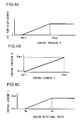
- FIG. 4A is a graph showing a relation between a control pressure P and the displacement of the HST pump 180.
- the displacement is set to be a minimum value in a range where the control pressure P is less than Pmin, increases according to increase of the control pressure P in a range where the control pressure P is not less than Pmin and less than Pmax, and is set to be a maximum value when the control pressure P is Pmax.
- FIG. 4B is a graph showing a relation between a control current I and the control pressure P (a secondary pressure) of the solenoid proportional valve 20.
- a degree of pressure reduction of the solenoid proportional valve 20 is controlled by the control current I from the controller 10.
- a valve characteristic of the solenoid proportional valve 20 is set so that the degree of pressure reduction becomes smaller, i.e., the control pressure P, which is the secondary pressure, becomes larger, along with increase of the control current I input to the solenoid.
- FIG. 4C is a graph showing a relation between the engine rotational speed and the control current I.
- Characteristics of the control current I with respect to the engine rotational speed shown in FIG. 4C are stored in a storage device of the controller 10 in a form of a lookup table.
- the control current I increases from the minimum value Imin to the maximum value Imax in accordance with increase in the engine rotational speed in a range where the engine rotational speed is not less than Ny and less than Nx.
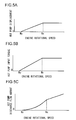
- FIGS. 5A, 5B, and 5C are graphs showing characteristics of the displacement, input torque, and the discharge flow amount of the HST pump 180 with respect to the engine rotational speed.
- Ny is an engine rotational speed at which the HST pump 180 starts discharge, and it is hereinafter described as the discharge starting speed Ny.
- the discharge starting speed Ny is set to be a value not less than a low-idle rotational speed Ns (Ny ⁇ Ns).
- FIG. 5A is the graph showing the characteristic of the displacement of the HST pump 180 with respect to the engine rotational speed.
- the control pressure P according to the control current I is output from the solenoid proportional valve 20, and the displacement of the HST pump 180 is controlled. That is, the displacement of the HST pump 180 is increased according to rise of the engine rotational speed as shown in FIG. 5A .
- the displacement is zero in a range where the engine rotational speed is less than the discharge starting speed Ny.
- the control pressure rises in proportion to the increase in the engine rotational speed, and the displacement of the HST pump 180 increases.
- the displacement of the HST pump 180 becomes a maximum one in a range where the engine rotational speed is not less than Nx.
- FIG. 5B is the graph showing the characteristic of the input torque of the HST pump 180 with respect to the engine rotational speed.
- the HST pump input torque is decided by the displacement and a circuit pressure of an HST traveling circuit.
- FIG. 5B shows the HST pump input torque characteristic when the circuit pressure is set as a relief pressure.
- the input torque of the HST pump 180 increases according to increase in the displacement of the HST pump 180. As described above, since the displacement of the HST pump 180 increases in proportion to the rise of the engine rotational speed, the HST pump input torque increases in proportion to the increase in the engine rotational speed as shown in FIG. 5B .
- FIG. 5C is the graph showing the characteristic of the discharge flow amount of the HST pump 180 with respect to the engine rotational speed.
- the discharge flow amount is zero in the range where the engine rotational speed is less than the discharge starting speed Ny. Since both of the rotational speed and the displacement of the HST pump 180 increase in the range where the engine rotational speed is not less than the discharge starting speed Ny and less than Nx, the discharge flow amount of the HST pump 180 increases curvilinearly and smoothly with good responsiveness according to the increase in the engine rotational speed, and smooth and strong acceleration can be obtained. Since the displacement is the maximum one in the range where the engine rotational speed is not less than Nx (refer to FIG. 5A ), the discharge flow amount of the HST pump 180 linearly increases according to the increase in the engine rotational speed.
- the hydraulic motor 181 shown in FIG. 2 is a variable displacement motor, a control signal is output to a tilt control device, which is not shown, from the controller 10, and a displacement (motor capacity) is controlled.
- the displacement of the hydraulic motor 181 is controlled according to a traveling circuit pressure of the HST traveling circuit.
- the remaining amount sensor 163 that detects a remaining amount of the urea water in the urea water tank 162 and outputs a remaining amount signal to the controller 10.
- the remaining amount sensor 163 is a water level sensor that detects a water level of the urea water in the urea water tank 162.
- FIGS. 6A, 6B and 6C are torque diagrams of the wheel loader according to the first embodiment, they show relations between an engine rotational speed and torque when the accelerator pedal 152 is stepped at the maximum, and show an engine output torque characteristic, a working pump input torque characteristic, and an HST pump input torque characteristic.
- a plurality of engine output torque characteristics A0, A1, and A2 are stored in the storage device of the controller 10 in a form of a lookup table.
- the characteristic A0 is used when the remaining amount of the urea water is not less than a first predetermined amount (an unlimited stage (or phase))
- the characteristic A1 is used when the remaining amount of the urea water is less than the first predetermined amount and not less than a second predetermined amount (a first limited stage (or phase))
- the characteristic A2 is used when the remaining amount of the urea water is less than the second predetermined amount (a second limited stage (or phase)).
- the engine output torque characteristics A0, A1, and A2 show relations between an engine rotational speed and maximum engine output torque, respectively.
- the maximum engine output torque means maximum torque that the engine 190 can output in each rotational speed.
- a region prescribed by an engine output torque characteristic shows performance that the engine 190 can exhibit.
- the engine mounted in the wheel loader has a droop characteristic in which torque rapidly reduces in a rotational speed region exceeding a rated point (rated highest torque) P0.
- a droop line is defined by a straight line that connects the rated point and an engine maximum rotational speed in a no-load state of the pump.
- matching control is performed utilizing such engine output torque characteristic, and the engine 190, the working pump 11 and the HST pump 180 are operated at a matching point, which will be mentioned later.
- the engine output torque characteristic A0 torque increases according to rise of the engine rotational speed in a range where the engine rotational speed is not less than a minimum rotational speed (a low-idle rotational speed) Ns and not more than Nv0, and torque becomes a maximum value (a maximum torque point Tm0) in the characteristic A0 when the engine rotational speed is Nv0.
- the low-idle rotational speed is an engine rotational speed at the time of non-operation of the accelerator pedal 152.
- the engine output torque characteristic A0 when the engine rotational speed becomes larger than Nv0, torque decreases according to the rise of the engine rotational speed, and when the torque reaches the rated point P0, a rated output can be obtained.
- torque When the engine rotational speed rises exceeding a rated rotational speed NP0 in the rated point P0, torque rapidly decreases.
- the engine output torque characteristic A1 is the same characteristic as the characteristic A0 in a range where the engine rotational speed is not less than (more than and equal to) the low-idle rotational speed Ns and not more than (less than and equal to) a threshold value Nq1 (a limit starting point Q1).
- a threshold value Nq1 a limit starting point Q1
- the threshold value Nq1 is set to be a value not less than the discharge starting speed Ny (Nq1 ⁇ Ny).
- the engine output torque characteristic A2 is the same characteristic as the characteristic A0 in a range where the engine rotational speed is not less than the low-idle rotational speed Ns and not more than a threshold value Nq2 (a limit starting point Q2).
- a threshold value Nq2 a limit starting point Q2
- torque decreases according to the rise of the engine rotational speed. That is, in the engine output torque characteristic A2, when the engine rotational speed is Nq2 smaller than Nv1 (Nq2 ⁇ Nv1), torque becomes a maximum value (a maximum torque point Tm2) in the characteristic A2.
- a torque value in the maximum torque point Tm2 is smaller than a torque value of the maximum torque point Tm1 in the characteristic A1.
- the threshold value Nq2 is set to be a value not less than the discharge starting speed Ny (Nq2 ⁇ Ny).
- the threshold value Nq2 is smaller than the threshold value Nq1 (Nq2 ⁇ Nq1).
- the working pump input torque characteristic B shows a relation between the engine rotational speed and maximum pump input torque (maximum pump absorption torque). Since the working pump 11 is a fixed displacement pump, the working pump input torque characteristic B becomes a constant value regardless of the engine rotational speed.
- An HST pump input torque characteristic H is the characteristic shown in FIG. 5B , and it is decided based on the displacement of the HST pump 180 that increases according to the rise of the engine rotational speed, and the traveling circuit pressure (a motor driving pressure).
- the traveling circuit pressure a motor driving pressure
- torque gradually increases according to the rise of the engine rotational speed in the range where the engine rotational speed is not less than the threshold value Ny and less than Nx.
- the torque becomes a maximum value in the characteristic H regardless of the engine rotational speed in the range where the engine rotational speed is not less than the threshold value Nx larger than Ny.
- intersections MC0, MC1, and MC2 of each of the characteristics A0, A1, and A2 with the characteristic H, and intersections MB0, MB1, and MB2 of each of the characteristics A0, A1, and A2 with the characteristic B are matching points.
- Engine output torque and HST pump input torque in a state (hereinafter described as a traveling system single operation state) where the traveling drive device (traveling system) is actuated without actuating the front work device (work system) become values of the intersections MC0, MC1, and MC2.
- Engine output torque and working pump input torque in a state (hereinafter described as a work system single operation state) where the front work device (work system) is actuated without actuating the traveling drive device (traveling system) become values of the intersections MB0, MB1, and MB2.
- the controller 10 is functionally provided with a remaining amount determination unit 10a and a selection unit 10b.
- the remaining amount determination unit 10a determines whether a remaining amount (water level) h of the urea water detected by the remaining amount sensor 163 is not less than or less than a predetermined amount. If the remaining amount h of the urea water is not less than a first predetermined amount h1, i.e., if the urea water is sufficiently stored, the remaining amount determination unit 10a determines the urea water to be in the unlimited stage.
- the remaining amount determination unit 10a determines the urea water to be in the first limited stage. If the remaining amount h of the urea water is less than the second predetermined amount h2, the remaining amount determination unit 10a determines the urea water to be in the second limited stage. Information on the first predetermined amount h1, and the second predetermined amount h2 smaller than the first predetermined amount h1 is previously stored in the storage device of the controller 10.
- the selection unit 10b selects the engine output torque characteristic according to a result determined by the remaining amount determination unit 10a. If the urea water is determined to be in the unlimited stage by the remaining amount determination unit 10a, the selection unit 10b selects the engine output torque characteristic A0. If the urea water is determined to be in the first limited stage by the remaining amount determination unit 10a, the selection unit 10b selects the engine output torque characteristic A1. If the urea water is determined to be in the second limited stage by the remaining amount determination unit 10a, the selection unit 10b selects the engine output torque characteristic A2.
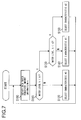
- FIG. 7 is the flow chart showing operation of limiting control processing of engine output torque by the controller 10.
- step S100 information on a remaining amount detected by the remaining amount sensor 163, i.e., on a water level in the urea water tank 162 is obtained, and the processing proceeds to step S110.
- step S110 the remaining amount determination unit 10a determines whether or not the remaining amount h of the urea water obtained in step S100 is less than the first predetermined amount h1. If negative determination is performed in step S110, the remaining amount determination unit 10a determines the urea water to be in the unlimited stage, and the processing proceeds to step S120, while if affirmative determination is performed, the processing proceeds to step S130.
- step S120 the selection unit 10b selects the engine output torque characteristic A0 from the storage device, and the processing returns to step S100.
- step S130 the remaining amount determination unit 10a determines whether or not the remaining amount h of the urea water obtained in step S100 is less than the second predetermined amount h2. If negative determination is performed in step S130, the remaining amount determination unit 10a determines the urea water to be in the first limited stage, and the processing proceeds to step S140, while if affirmative determination is performed, the remaining amount determination unit 10a determines the urea water to be in the second limited stage, and the processing proceeds to step S150,
- step S140 the selection unit 10b selects the engine output torque characteristic A1 from the storage device, and the processing returns to step S100.
- step S150 the selection unit 10b selects the engine output torque characteristic A2 from the storage device, and the processing returns to step S100.
- the engine output torque characteristic is changed according to the decrease of the urea water remaining amount.
- the controller 10 controls a fuel injection amount of the engine 190 based on the target engine rotational speed by the accelerator pedal 152 and the actual rotational speed detected by the rotational speed sensor 13 with reference to characteristic tables (A0, A1, and A2) selected by the selection unit 10b.
- the controller 10 calculates the control current I based on the actual rotational speed detected by the rotational speed sensor 13 with reference to the characteristic table shown in FIG. 4C , and controls the displacement of the HST pump 180 by controlling the control pressure from the solenoid proportional valve 20.
- FIGS. 9A and 9B are torque diagrams of a wheel loader according to the second embodiment of the present invention.
- the output torque of the engine 190 is decreased, and also a maximum rotational speed of the engine 190 is decreased.
- Engine output torque characteristics A21 and A22 are stored in the storage device of the controller 10 instead of the engine output torque characteristics A1 and A2, which have been explained in the first embodiment.
- the characteristics A0, B, and H are similar to those in the first embodiment.
- the engine output torque characteristic A21 is the characteristic in which the characteristic A0 has been shifted to low rotation and low torque side
- the engine output torque characteristic A22 is the characteristic in which the characteristic A21 has been further shifted to low rotation and low torque side.
- each characteristic is set so that a torque maximum value in the each characteristic becomes smaller in order of the characteristic A0 (the maximum torque point Tm0), the characteristic A21 (a maximum torque point Tm21), and the characteristic A22 (a maximum torque point Tm22).
- each characteristic is set so that the engine rotational speed in the maximum torque point becomes smaller in order of the characteristic A1, the characteristic A21, and the characteristic A22.
- Reference characters P0, P1, and P2 are rated points at which rated outputs can be obtained in the characteristics A0, A21, and A22, respectively. As shown in FIG. 9A , an engine rotational speed in the rated point P0 is NP0, an engine rotational speed in the rated point P1 is NP1 smaller than NP0, and an engine rotational speed in the rated point P2 is NP2 smaller than NP1 (NP2 ⁇ NP1 ⁇ NP0).
- the engine rotational speed for obtaining the rated output in each characteristic is set so as to be smaller in stages according to the decrease of the remaining amount of the urea water.
- each characteristic is set so that the engine maximum rotational speed at the time of no load of the pump becomes smaller in order of the characteristics A0, A21, and A22.
- the HST pump input torque and the engine rotational speed become values of a matching point MC20 in the traveling system single operation state in the unlimited stage
- the working pump input torque and the engine rotational speed in the work system single operation state in the unlimited stage become values of the matching point MB0.
- the HST pump input torque and the engine rotational speed become values of a matching point MC21 in the traveling system single operation state in the first limited stage, and the working pump input torque and the engine rotational speed in the work system single operation state in the first limited stage become values of a matching point MB21.
- the HST pump input torque and the engine rotational speed become values of a matching point MC22 in the traveling system single operation state in the second limited stage, and the working pump input torque and the engine rotational speed in the work system single operation state in the second limited stage become values of a matching point MB22.
- the characteristics A21 and A22 may be set so that the matching points MB21 and MB22 become the same as the matching points MB1 and MB2 of the first embodiment.
Landscapes
- Engineering & Computer Science (AREA)
- General Engineering & Computer Science (AREA)
- Mining & Mineral Resources (AREA)
- Civil Engineering (AREA)
- Structural Engineering (AREA)
- Mechanical Engineering (AREA)
- Chemical & Material Sciences (AREA)
- Combustion & Propulsion (AREA)
- Chemical Kinetics & Catalysis (AREA)
- Control Of Vehicle Engines Or Engines For Specific Uses (AREA)
- Operation Control Of Excavators (AREA)
- Exhaust Gas After Treatment (AREA)
Abstract
Description
- The disclosure of the following priority application is herein incorporated by reference: Japanese Patent Application No.
2013-208252 filed October 3, 2013 - The present invention relates to a work vehicle provided with an exhaust gas purification device that purifies exhaust gas discharged from an engine that drives a hydraulic pump.
- There has been known an automobile provided with an exhaust gas purification device that reduces nitrogen oxide in exhaust gas and removes it (refer to Japanese Laid-Open Patent Publication No.
2002-371831 2002-371831 - Since a technology described in the above-mentioned Japanese Laid-Open Patent Publication No.
2002-371831 - In the work vehicle, a load of the engine changes according to an operation state (a work state and a traveling state) of the vehicle, such as a state of traveling without driving the front work device, a state of driving the front work device while making the vehicle travel, or a state of driving the front work device in a stopped state. When the above-mentioned technology described in Japanese Laid-Open No.
2002-371831 - According to the 1 st aspect of the present invention, a work vehicle including a front work device, comprises: a hydraulic pump driven by an engine; a hydraulic motor that is connected to the hydraulic pump in a closed circuit and is driven by pressure oil discharged from the hydraulic pump; a rotational speed detection unit that detects an actual rotational speed of the engine; an exhaust gas purification device that purifies nitrogen oxide in exhaust gas discharged from the engine using a reducing agent solution stored in a reducing agent tank; a remaining amount detection device that detects a remaining amount of the reducing agent solution in the reducing agent tank; a torque control unit that decreases output torque of the engine according to decrease of the remaining amount of the reducing agent solution detected by the remaining amount detection device; and a storage device that stores a threshold value not less than an engine rotational speed at which the hydraulic pump starts discharge, wherein when the actual rotational speed of the engine detected by the rotational speed detection unit is not more than the threshold value stored in the storage device, the torque control unit does not decrease the output torque of the engine regardless of the remaining amount of the reducing agent solution detected by the remaining amount detection device.
- According to the 2nd aspect of the present invention, in the work vehicle according to the 1 st aspect, it is preferred that the torque control unit decreases the output torque of the engine in stages and also decreases the threshold value according to the decrease of the remaining amount of the reducing agent solution detected by the remaining amount detection device.
- According to the 3rd aspect of the present invention, in the work vehicle according to the 1st or 2nd aspect, it is preferred that the torque control unit decreases the output torque of the engine and also decreases a rotational speed of the engine in a rated point according to the decrease of the remaining amount of the reducing agent solution detected by the remaining amount detection device.
- According to the 4th aspect of the present invention, in the work vehicle according to any one of the 1 st to 3rd aspects, it is preferred that an engine rotational speed at which the hydraulic pump starts discharge is set to be not less than a low-idle rotational speed of the engine.
- According to the 5th aspect of the present invention, in the work vehicle according to any one of the 1 st to 4th aspects, it is preferred that the work vehicle further comprises a fixed displacement hydraulic pump that supplies pressure oil to an actuator that drives the front work device.
-
-
FIG. 1 is a side view of a wheel loader that is one example of a work vehicle according to a first embodiment of the present invention; -
FIG. 2 is a diagram showing a schematic configuration of the wheel loader according to the first embodiment of the present invention; -
FIG. 3 is a diagram showing a configuration of a regulator ofFIG. 2 ; -
FIG. 4A is a graph showing a relation between a control pressure and a displacement of an HST pump,FIG. 4B is a graph showing a relation between a control current and a control pressure (a secondary pressure) of a solenoid proportional valve, andFIG. 4C is a graph showing a relation between an engine rotational speed and a control current; -
FIG. 5A is a graph showing a characteristic of the displacement of the HST pump with respect to an engine rotational speed,FIG. 5B is a graph showing a characteristic of input torque of the HST pump with respect to the engine rotational speed, andFIG. 5C is a graph showing a characteristic of a discharge flow amount of the HST pump with respect to the engine rotational speed; -
FIGS. 6A, 6B, and 6C are torque diagrams of the wheel loader according to the first embodiment of the present invention; -
FIG. 7 is a flow chart showing operation of limiting control processing of engine output torque by a controller; -
FIG. 8 is a diagram showing excavation work by the wheel loader; and -
FIGS. 9A and 9B are torque diagrams of a wheel loader according to a second embodiment of the present invention. - Hereinafter, one embodiment of a work vehicle according to the present invention will be explained with reference to drawings.
-
FIG. 1 is a side view of a wheel loader that is one example of a work vehicle according to a first embodiment. The wheel loader includes: afront vehicle body 110 having anarm 111, abucket 112, front wheels, etc.; and arear vehicle body 120 having an operator'scab 121, amachine room 122, rear wheels, etc. - The
arm 111 turns (rises and lowers) in a up and down (vertical) direction by drive of anarm cylinder 117, and thebucket 112 turns (crowds or dumps) in the up and down (vertical) direction by drive of abucket cylinder 115. Thefront vehicle body 110 and therear vehicle body 120 are turnably coupled to each other bycenter pins 101, and thefront vehicle body 110 bends from side to side with respect to therear vehicle body 120 by expansion and contraction of asteering cylinder 116. - An upper side of the
machine room 122 is covered with anengine hood 140, and sides thereof are covered with anopenable housing cover 141. To theengine hood 140, attached are anair intake pipe 170 for taking in the air needed for drive of anengine 190 from outside, and atail pipe 171 for discharging exhaust gas. Theengine 190 and an exhaust gas purification device (an exhaust emission control device) 160 are arranged in themachine room 122. -
FIG. 2 is a diagram showing a schematic configuration of the wheel loader according to the first embodiment. As shown inFIG. 2 , the wheel loader has a so-called HST (Hydro Static Transmission) traveling drive device (traveling system), and has a hydraulic pump (hereinafter described as an HST pump 180) driven by theengine 190, and ahydraulic motor 181 that is connected to theHST pump 180 in a closed circuit. When thehydraulic motor 181 rotates by pressure oil discharged from theHST pump 180, output torque of thehydraulic motor 181 is transmitted to anoutput shaft 186 through a gearbox, which is not shown. Consequently,tires 113 rotate through anaxle 187, and the vehicle travels. - The
HST pump 180 is a swash plate type or a bent axis type variable displacement hydraulic pump in which a displacement is changed according to a tilt angle. The displacement is controlled by aregulator 182.FIG. 3 is a diagram showing a configuration of theregulator 182 ofFIG. 2 . As shown inFIG. 3 , theregulator 182 has: a tilt (displacement)cylinder 18; a forward andreverse switching valve 19 that is switched according to operation of a forward andreverse switching switch 17; and a solenoid (electromagnetic) proportional pressure reducing valve (hereinafter described as a solenoid proportional valve 20) that adjusts a control pressure according to a control signal from acontroller 10. Pressure oil from acharge pump 8 driven by theengine 190 is pressure-reduced through the solenoidproportional valve 20, and is guided to thetilt cylinder 18 through the forward andreverse switching valve 19 as the control pressure. Note that a discharge pressure (a primary pressure) of thecharge pump 8 is limited to a predetermined value by arelief valve 12. The control pressure is supplied to thetilt cylinder 18 through the forward andreverse switching valve 19, the displacement is controlled according to the control pressure, and also an operation direction of thetilt cylinder 18 is controlled according to switching of the forward andreverse switching valve 19, and a tilt direction of theHST pump 180 is controlled. - As shown in
FIG. 2 , the wheel loader is provided with a front work device (work system) configured to include: a fixed displacement hydraulic pump (hereinafter described as a working pump 11); acontrol valve 21; anactuator 30; thearm 111; and thebucket 112. The workingpump 11 is driven by theengine 190, and discharges pressure oil. - The pressure oil discharged from the
working pump 11 is supplied to the workingactuator 30 through thecontrol valve 21, and theactuator 30 is driven. Thecontrol valve 21 is operated with acontrol lever 31, and controls a flow of the pressure oil from theworking pump 11 to theactuator 30. Note that inFIG. 2 , for convenience, an arm operation lever and a bucket operation lever are collectively described as thecontrol lever 31, thearm cylinder 117 and thebucket cylinder 115 are collectively described as theactuator 30, and an arm control valve or a bucket control valve is collectively described as thecontrol valve 21. The arm operation lever outputs a raising/lowering command of thearm 111, and the bucket operation lever outputs a tilting/dumping command of thebucket 112. - The exhaust
gas purification device 160 is provided with: atreatment device 161 that performs treatment to purify nitrogen oxide in exhaust gas discharged from theengine 190, for example, using a urea water solution (hereinafter described as urea water) as a reducing agent solution; aurea water tank 162 for storing urea water supplied to thetreatment device 161; and aremaining amount sensor 163 that detects a remaining amount of the urea water in theurea water tank 162. - The
controller 10 is configured to include an arithmetic processing device having a CPU, a ROM and a RAM, which are storage devices, other peripheral circuits, etc. - As shown in
FIG. 2 , to thecontroller 10, connected are an acceleratoroperation amount detector 152a that detects a pedal operation amount (a pedal stroke or a pedal angle) of anaccelerator pedal 152, and arotational speed sensor 13 that detects an actual rotational speed of theengine 190 and outputs an actual rotational speed signal to thecontroller 10. - The
controller 10 sets a target engine rotational speed of theengine 190 according to the pedal operation amount (stepping amount) of theaccelerator pedal 152 detected by the acceleratoroperation amount detector 152a. When the pedal operation amount of theaccelerator pedal 152 becomes large, the target engine rotational speed becomes large, and the target engine rotational speed at the time of maximum pedal stepping becomes a rated rotational speed in a rated point, which will be mentioned later. - The
controller 10 outputs a control signal corresponding to a set target engine rotational speed to anengine controller 9. Theengine controller 9 compares the actual rotational speed of theengine 190 detected by therotational speed sensor 13 with the target engine rotational speed from thecontroller 10, and controls a fuel injection device (not shown) in order to bring the actual rotational speed of theengine 190 close to the target engine rotational speed. - As shown in
FIG. 2 , the forward and reverse switchingswitch 17 that commands advance and back movement of the vehicle is connected to thecontroller 10, and an operation position (forward (F)/neutral (N)/reverse (R)) of the forward and reverse switchingswitch 17 is detected by thecontroller 10. Thecontroller 10 outputs the control signal to the forward and reverse switchingvalve 19 shown inFIG. 3 according to the operation position of the forward and reverse switchingswitch 17. The forward and reverse switchingvalve 19 is switched according to the input control signal, the control pressure is supplied to thetilt cylinder 18 through the forward and reverse switchingvalve 19, and the operation direction and an operation amount of thetilt cylinder 18 are controlled. As a result, the tilt direction and the displacement of theHST pump 180 are controlled. - When the forward and reverse switching
switch 17 is switched to a neutral (N) position, a pressure of each ofoil chambers tilt cylinder 18 becomes a tank pressure, and apiston 18c is located at a neutral position. For this reason, the displacement of theHST pump 180 becomes zero, and a pump discharge flow amount becomes zero. - When the forward and reverse switching
switch 17 is switched to a forward (F) position, the forward and reverse switchingvalve 19 is switched to an A side, and the pressure oil from thecharge pump 8 is pressure-reduced by the solenoidproportional valve 20 to act on theoil chamber 18a. The tank pressure acts on theoil chamber 18b. For this reason, a pressure difference occurs between theoil chambers tilt cylinder 18, thepiston 18c is displaced in a right direction shown inFIG. 3 , and the displacement of theHST pump 180 increases. TheHST pump 180 rotates to a forward side, and the discharge flow amount according to the engine rotational speed and the displacement is discharged from theHST pump 180. - When the forward and reverse switching
switch 17 is switched to a reverse (R) position, the forward and reverse switchingvalve 19 is switched to a B side, and the pressure oil from thecharge pump 8 is pressure-reduced by the solenoidproportional valve 20 to act on theoil chamber 18b. The tank pressure acts on theoil chamber 18a. For this reason, a pressure difference occurs between theoil chambers tilt cylinder 18, thepiston 18c is displaced in a left direction shown inFIG. 3 , and the displacement of theHST pump 180 increases. TheHST pump 180 rotates to a reverse side, and the discharge flow amount according to the engine rotational speed and the displacement is discharged from theHST pump 180. -
FIG. 4A is a graph showing a relation between a control pressure P and the displacement of theHST pump 180. The displacement is set to be a minimum value in a range where the control pressure P is less than Pmin, increases according to increase of the control pressure P in a range where the control pressure P is not less than Pmin and less than Pmax, and is set to be a maximum value when the control pressure P is Pmax. -
FIG. 4B is a graph showing a relation between a control current I and the control pressure P (a secondary pressure) of the solenoidproportional valve 20. A degree of pressure reduction of the solenoidproportional valve 20 is controlled by the control current I from thecontroller 10. A valve characteristic of the solenoidproportional valve 20 is set so that the degree of pressure reduction becomes smaller, i.e., the control pressure P, which is the secondary pressure, becomes larger, along with increase of the control current I input to the solenoid. -
FIG. 4C is a graph showing a relation between the engine rotational speed and the control current I. Characteristics of the control current I with respect to the engine rotational speed shown inFIG. 4C are stored in a storage device of thecontroller 10 in a form of a lookup table. In a characteristic table, the control current I = Imin is established in a range where the engine rotational speed is less than Ny, and the control current I = Imax is established in a range where the engine rotational speed is not less than Nx. In the characteristic table, the control current I increases from the minimum value Imin to the maximum value Imax in accordance with increase in the engine rotational speed in a range where the engine rotational speed is not less than Ny and less than Nx. -
FIGS. 5A, 5B, and 5C are graphs showing characteristics of the displacement, input torque, and the discharge flow amount of theHST pump 180 with respect to the engine rotational speed. InFIGS. 5A, 5B, and 5C , Ny is an engine rotational speed at which the HST pump 180 starts discharge, and it is hereinafter described as the discharge starting speed Ny. The discharge starting speed Ny is set to be a value not less than a low-idle rotational speed Ns (Ny ≥ Ns).FIG. 5A is the graph showing the characteristic of the displacement of theHST pump 180 with respect to the engine rotational speed. As described above, when the control current I is set based on the engine rotational speed, the control pressure P according to the control current I is output from the solenoidproportional valve 20, and the displacement of theHST pump 180 is controlled. That is, the displacement of theHST pump 180 is increased according to rise of the engine rotational speed as shown inFIG. 5A . - As shown in
FIG. 5A , the displacement is zero in a range where the engine rotational speed is less than the discharge starting speed Ny. In a range where the engine rotational speed is not less than the discharge starting speed Ny and less than Nx, the control pressure rises in proportion to the increase in the engine rotational speed, and the displacement of theHST pump 180 increases. The displacement of theHST pump 180 becomes a maximum one in a range where the engine rotational speed is not less than Nx. -
FIG. 5B is the graph showing the characteristic of the input torque of theHST pump 180 with respect to the engine rotational speed. The HST pump input torque is decided by the displacement and a circuit pressure of an HST traveling circuit.FIG. 5B shows the HST pump input torque characteristic when the circuit pressure is set as a relief pressure. The input torque of theHST pump 180 increases according to increase in the displacement of theHST pump 180. As described above, since the displacement of theHST pump 180 increases in proportion to the rise of the engine rotational speed, the HST pump input torque increases in proportion to the increase in the engine rotational speed as shown inFIG. 5B . -
FIG. 5C is the graph showing the characteristic of the discharge flow amount of theHST pump 180 with respect to the engine rotational speed. As shown inFIG. 5C , the discharge flow amount is zero in the range where the engine rotational speed is less than the discharge starting speed Ny. Since both of the rotational speed and the displacement of theHST pump 180 increase in the range where the engine rotational speed is not less than the discharge starting speed Ny and less than Nx, the discharge flow amount of theHST pump 180 increases curvilinearly and smoothly with good responsiveness according to the increase in the engine rotational speed, and smooth and strong acceleration can be obtained. Since the displacement is the maximum one in the range where the engine rotational speed is not less than Nx (refer toFIG. 5A ), the discharge flow amount of theHST pump 180 linearly increases according to the increase in the engine rotational speed. - The
hydraulic motor 181 shown inFIG. 2 is a variable displacement motor, a control signal is output to a tilt control device, which is not shown, from thecontroller 10, and a displacement (motor capacity) is controlled. The displacement of thehydraulic motor 181 is controlled according to a traveling circuit pressure of the HST traveling circuit. - To the
controller 10, connected is the remainingamount sensor 163 that detects a remaining amount of the urea water in theurea water tank 162 and outputs a remaining amount signal to thecontroller 10. The remainingamount sensor 163 is a water level sensor that detects a water level of the urea water in theurea water tank 162. -
FIGS. 6A, 6B and 6C are torque diagrams of the wheel loader according to the first embodiment, they show relations between an engine rotational speed and torque when theaccelerator pedal 152 is stepped at the maximum, and show an engine output torque characteristic, a working pump input torque characteristic, and an HST pump input torque characteristic. A plurality of engine output torque characteristics A0, A1, and A2 are stored in the storage device of thecontroller 10 in a form of a lookup table. As will be mentioned later, the characteristic A0 is used when the remaining amount of the urea water is not less than a first predetermined amount (an unlimited stage (or phase)), the characteristic A1 is used when the remaining amount of the urea water is less than the first predetermined amount and not less than a second predetermined amount (a first limited stage (or phase)), and the characteristic A2 is used when the remaining amount of the urea water is less than the second predetermined amount (a second limited stage (or phase)). - The engine output torque characteristics A0, A1, and A2 show relations between an engine rotational speed and maximum engine output torque, respectively. Note that the maximum engine output torque means maximum torque that the
engine 190 can output in each rotational speed. A region prescribed by an engine output torque characteristic (a maximum torque line) shows performance that theengine 190 can exhibit. The engine mounted in the wheel loader has a droop characteristic in which torque rapidly reduces in a rotational speed region exceeding a rated point (rated highest torque) P0. InFIGS. 3A, 3B ,4A, and 4B , a droop line is defined by a straight line that connects the rated point and an engine maximum rotational speed in a no-load state of the pump. In the wheel loader, matching control is performed utilizing such engine output torque characteristic, and theengine 190, the workingpump 11 and theHST pump 180 are operated at a matching point, which will be mentioned later. - As shown in
FIG. 6A , in the engine output torque characteristic A0, torque increases according to rise of the engine rotational speed in a range where the engine rotational speed is not less than a minimum rotational speed (a low-idle rotational speed) Ns and not more than Nv0, and torque becomes a maximum value (a maximum torque point Tm0) in the characteristic A0 when the engine rotational speed is Nv0. Note that the low-idle rotational speed is an engine rotational speed at the time of non-operation of theaccelerator pedal 152. In the engine output torque characteristic A0, when the engine rotational speed becomes larger than Nv0, torque decreases according to the rise of the engine rotational speed, and when the torque reaches the rated point P0, a rated output can be obtained. When the engine rotational speed rises exceeding a rated rotational speed NP0 in the rated point P0, torque rapidly decreases. - As shown in
FIG. 6B , the engine output torque characteristic A1 is the same characteristic as the characteristic A0 in a range where the engine rotational speed is not less than (more than and equal to) the low-idle rotational speed Ns and not more than (less than and equal to) a threshold value Nq1 (a limit starting point Q1). In the engine output torque characteristic A1, when the engine rotational speed becomes larger than the threshold value Nq1, an increasing rate of torque according to the rise of the engine rotational speed decreases compared with the characteristic A0. The threshold value Nq1 is set to be a value not less than the discharge starting speed Ny (Nq1 ≥ Ny). - In the engine output torque characteristic A1, when the engine rotational speed is Nv1 smaller than Nv0 (Nv1 < Nv0), torque becomes a maximum value (a maximum torque point Tm1) in the characteristic A1. A torque value in the maximum torque point Tm1 is smaller than a torque value of the maximum torque point Tm0 in the characteristic A0. In the engine output torque characteristic A1, when the engine rotational speed becomes larger than Nv1, torque decreases according to the rise of the engine rotational speed.
- As shown in
FIG. 6C , the engine output torque characteristic A2 is the same characteristic as the characteristic A0 in a range where the engine rotational speed is not less than the low-idle rotational speed Ns and not more than a threshold value Nq2 (a limit starting point Q2). In the engine output torque characteristic A2, when the engine rotational speed becomes larger than the threshold value Nq2, torque decreases according to the rise of the engine rotational speed. That is, in the engine output torque characteristic A2, when the engine rotational speed is Nq2 smaller than Nv1 (Nq2 < Nv1), torque becomes a maximum value (a maximum torque point Tm2) in the characteristic A2. A torque value in the maximum torque point Tm2 is smaller than a torque value of the maximum torque point Tm1 in the characteristic A1. The threshold value Nq2 is set to be a value not less than the discharge starting speed Ny (Nq2 ≥ Ny). The threshold value Nq2 is smaller than the threshold value Nq1 (Nq2 < Nq1). - The working pump input torque characteristic B shows a relation between the engine rotational speed and maximum pump input torque (maximum pump absorption torque). Since the working
pump 11 is a fixed displacement pump, the working pump input torque characteristic B becomes a constant value regardless of the engine rotational speed. - An HST pump input torque characteristic H is the characteristic shown in
FIG. 5B , and it is decided based on the displacement of theHST pump 180 that increases according to the rise of the engine rotational speed, and the traveling circuit pressure (a motor driving pressure). As shown inFIG. 6A , in the characteristic H, torque gradually increases according to the rise of the engine rotational speed in the range where the engine rotational speed is not less than the threshold value Ny and less than Nx. In the characteristic H, the torque becomes a maximum value in the characteristic H regardless of the engine rotational speed in the range where the engine rotational speed is not less than the threshold value Nx larger than Ny. - As shown in
FIGS. 6A, 6B, and 6C , intersections MC0, MC1, and MC2 of each of the characteristics A0, A1, and A2 with the characteristic H, and intersections MB0, MB1, and MB2 of each of the characteristics A0, A1, and A2 with the characteristic B are matching points. - Engine output torque and HST pump input torque in a state (hereinafter described as a traveling system single operation state) where the traveling drive device (traveling system) is actuated without actuating the front work device (work system) become values of the intersections MC0, MC1, and MC2. Engine output torque and working pump input torque in a state (hereinafter described as a work system single operation state) where the front work device (work system) is actuated without actuating the traveling drive device (traveling system) become values of the intersections MB0, MB1, and MB2.
- As shown in
FIG. 2 , thecontroller 10 is functionally provided with a remainingamount determination unit 10a and aselection unit 10b. The remainingamount determination unit 10a determines whether a remaining amount (water level) h of the urea water detected by the remainingamount sensor 163 is not less than or less than a predetermined amount. If the remaining amount h of the urea water is not less than a first predetermined amount h1, i.e., if the urea water is sufficiently stored, the remainingamount determination unit 10a determines the urea water to be in the unlimited stage. If the remaining amount h of the urea water is less than the first predetermined amount h1 and not less than a second predetermined amount h2, the remainingamount determination unit 10a determines the urea water to be in the first limited stage. If the remaining amount h of the urea water is less than the second predetermined amount h2, the remainingamount determination unit 10a determines the urea water to be in the second limited stage. Information on the first predetermined amount h1, and the second predetermined amount h2 smaller than the first predetermined amount h1 is previously stored in the storage device of thecontroller 10. - The
selection unit 10b selects the engine output torque characteristic according to a result determined by the remainingamount determination unit 10a. If the urea water is determined to be in the unlimited stage by the remainingamount determination unit 10a, theselection unit 10b selects the engine output torque characteristic A0. If the urea water is determined to be in the first limited stage by the remainingamount determination unit 10a, theselection unit 10b selects the engine output torque characteristic A1. If the urea water is determined to be in the second limited stage by the remainingamount determination unit 10a, theselection unit 10b selects the engine output torque characteristic A2. - Hereinafter, limiting control of engine output torque performed according to the remaining amount of the urea water will be explained using a flow chart of
FIG. 7. FIG. 7 is the flow chart showing operation of limiting control processing of engine output torque by thecontroller 10. When an ignition switch (not shown) is turned on, a program that performs processing shown inFIG. 7 is started, and is repeatedly executed by thecontroller 10. - In step S100, information on a remaining amount detected by the remaining
amount sensor 163, i.e., on a water level in theurea water tank 162 is obtained, and the processing proceeds to step S110. - In step S110, the remaining
amount determination unit 10a determines whether or not the remaining amount h of the urea water obtained in step S100 is less than the first predetermined amount h1. If negative determination is performed in step S110, the remainingamount determination unit 10a determines the urea water to be in the unlimited stage, and the processing proceeds to step S120, while if affirmative determination is performed, the processing proceeds to step S130. - In step S120, the
selection unit 10b selects the engine output torque characteristic A0 from the storage device, and the processing returns to step S100. - In step S130, the remaining
amount determination unit 10a determines whether or not the remaining amount h of the urea water obtained in step S100 is less than the second predetermined amount h2. If negative determination is performed in step S130, the remainingamount determination unit 10a determines the urea water to be in the first limited stage, and the processing proceeds to step S140, while if affirmative determination is performed, the remainingamount determination unit 10a determines the urea water to be in the second limited stage, and the processing proceeds to step S150, - In step S140, the
selection unit 10b selects the engine output torque characteristic A1 from the storage device, and the processing returns to step S100. - In step S150, the
selection unit 10b selects the engine output torque characteristic A2 from the storage device, and the processing returns to step S100. - As described above, in the present embodiment, the engine output torque characteristic is changed according to the decrease of the urea water remaining amount. The
controller 10 controls a fuel injection amount of theengine 190 based on the target engine rotational speed by theaccelerator pedal 152 and the actual rotational speed detected by therotational speed sensor 13 with reference to characteristic tables (A0, A1, and A2) selected by theselection unit 10b. Thecontroller 10 calculates the control current I based on the actual rotational speed detected by therotational speed sensor 13 with reference to the characteristic table shown inFIG. 4C , and controls the displacement of theHST pump 180 by controlling the control pressure from the solenoidproportional valve 20. - According to the first embodiment explained above, next operational effects can be obtained.
- (1) The output torque of the
engine 190 was decreased according to the decrease of the remaining amount of the urea water in theurea water tank 162. Consequently, an operator can recognize that there is a little remaining amount of the urea water since an operation state is getting worse compared with an ordinary time. That is, according to the present embodiment, high-output operation in a state where the remaining amount of the urea water has decreased is prevented, and the operator can be urged to replenish the urea water. - (2) When the actual rotational speed of the
engine 190 was in a low rotational speed region, the output torque of theengine 190 was made not to decrease regardless of the remaining amount of the reducing agent solution. In the present embodiment, even in a case where the remaining amount of the urea water decreased, and where the stage changed from the unlimited stage to the first limited stage, the output torque of theengine 190 was made not to decrease in a range where the actual rotational speed of theengine 190 was not more than the threshold value Nq1. Even in a case where the remaining amount of the urea water decreased, and where the stage changed from the first limited stage to the second limited stage, the output torque of theengine 190 was made not to decrease in a range where the actual rotational speed of theengine 190 was not more than the threshold value Nq2. Furthermore, the threshold values Nq1 and Nq2 of the engine rotational speeds in the limit starting points Q1 and Q2 of the engine output torque were set to be not less than the discharge starting speed Ny. Consequently, even in a case where a load corresponding to the relief pressure of the workingpump 11 acts in a state where theengine 190 is rotating in the low rotational speed region, engine stall is prevented from occurring.
For example, as shown inFIG. 8 , in the wheel loader, excavation work is performed by the following: thebucket 112 is thrust into anatural ground 130; thearm 111 is operated upwardly after operating thebucket 112; or only thearm 111 is finally operated upwardly while simultaneously operating thebucket 112 and thearm 111. The operator performs return operation of theaccelerator pedal 152 just before thrusting into thenatural ground 130. For this reason, the engine rotational speed is in the low rotational speed region (for example, a speed region not more than Nq2) at the time of the thrust to thenatural ground 130. The operator again performs stepping operation of theaccelerator pedal 152 at the same time of the thrust into thenatural ground 130, makes thebucket 112 penetrate thenatural ground 130, and also makes the front work device work to perform the excavation work. At this time, since a traveling load and a work load rapidly rise, engine stall might occur when the engine output torque is decreased also in the low rotational speed region according to the decrease in the urea water remaining amount. In contrast with this, in the present embodiment, for example, at the time of the second limited stage, the engine output torque was made not to decrease in the range where the actual engine rotational speed was not more than Nq2 (Ns ≤ Nq2). For this reason, even in the case where the engine output torque is decreased according to the decrease of the remaining amount of the urea water, the operator can continue his work, and can replenish the urea water at a desired time after completing predetermined work. - (3) The discharge starting speed Ny at which the HST pump 180 starts discharge is set to be not less than the low-idle rotational speed Ns of the
engine 190. For this reason, occurrence of engine stall in the low rotational speed region can be prevented more reliably. - A second embodiment of the present invention will be explained with reference to
FIGS. 9A and 9B . Note that the same symbol is attached to the same portion as the first embodiment or a portion corresponding thereto, and that a difference from the first embodiment is mainly explained. A point where the second embodiment differs from the first embodiment is an engine output torque characteristic stored in the storage device of thecontroller 10.FIGS. 9A and 9B are torque diagrams of a wheel loader according to the second embodiment of the present invention. - As shown in
FIGS. 9A and 9B , in the second embodiment, according to the decrease of the remaining amount of the urea water, the output torque of theengine 190 is decreased, and also a maximum rotational speed of theengine 190 is decreased. Engine output torque characteristics A21 and A22 are stored in the storage device of thecontroller 10 instead of the engine output torque characteristics A1 and A2, which have been explained in the first embodiment. The characteristics A0, B, and H are similar to those in the first embodiment. - The engine output torque characteristic A21 is the characteristic in which the characteristic A0 has been shifted to low rotation and low torque side, and the engine output torque characteristic A22 is the characteristic in which the characteristic A21 has been further shifted to low rotation and low torque side. Similarly to the first embodiment, each characteristic is set so that a torque maximum value in the each characteristic becomes smaller in order of the characteristic A0 (the maximum torque point Tm0), the characteristic A21 (a maximum torque point Tm21), and the characteristic A22 (a maximum torque point Tm22). In addition, each characteristic is set so that the engine rotational speed in the maximum torque point becomes smaller in order of the characteristic A1, the characteristic A21, and the characteristic A22.
- Reference characters P0, P1, and P2 are rated points at which rated outputs can be obtained in the characteristics A0, A21, and A22, respectively. As shown in
FIG. 9A , an engine rotational speed in the rated point P0 is NP0, an engine rotational speed in the rated point P1 is NP1 smaller than NP0, and an engine rotational speed in the rated point P2 is NP2 smaller than NP1 (NP2 < NP1 < NP0). - That is, in the second embodiment, the engine rotational speed for obtaining the rated output in each characteristic is set so as to be smaller in stages according to the decrease of the remaining amount of the urea water. In other words, each characteristic is set so that the engine maximum rotational speed at the time of no load of the pump becomes smaller in order of the characteristics A0, A21, and A22.
- As shown in
FIG. 9B , the HST pump input torque and the engine rotational speed become values of a matching point MC20 in the traveling system single operation state in the unlimited stage, and the working pump input torque and the engine rotational speed in the work system single operation state in the unlimited stage become values of the matching point MB0. - As shown in
FIG. 9B , the HST pump input torque and the engine rotational speed become values of a matching point MC21 in the traveling system single operation state in the first limited stage, and the working pump input torque and the engine rotational speed in the work system single operation state in the first limited stage become values of a matching point MB21. - As shown in
FIG. 9B , the HST pump input torque and the engine rotational speed become values of a matching point MC22 in the traveling system single operation state in the second limited stage, and the working pump input torque and the engine rotational speed in the work system single operation state in the second limited stage become values of a matching point MB22. - Note that the characteristics A21 and A22 may be set so that the matching points MB21 and MB22 become the same as the matching points MB1 and MB2 of the first embodiment.
- According to such second embodiment, operational effects similar to those in the first embodiment are exerted. In the second embodiment, since the rotational speed of the
engine 190 in the rated point is decreased according to the decrease of the remaining amount of the urea water, a highest vehicle speed decreases, traveling acceleration slightly decreases, and an operation speed of the front work device decreases. For this reason, the operator can be urged more clearly to replenish the urea water compared with the first embodiment. - The following modifications also fall within the scope of the present invention, and it is also possible to combine one or more modified examples with the above-mentioned embodiments.
- (1) As an example of combining the plurality of embodiments, for example, the engine output torque characteristic A1, which has been explained in the first embodiment, may be selected in the first limited stage, and the engine output torque characteristic A22, which has been explained in the second embodiment, may be selected in the second limited stage.
- (2) Although in the above-mentioned embodiments, the example has been explained where an engine output torque characteristic is changed according to the three stages of the unlimited stage, the first limited stage, and the second limited stage, the present invention is not limited to this. For example, stages may be separated into four or more stages, and the engine output torque characteristic may be changed.
- (3) In the first embodiment, the engine output torque characteristics are decreased in stages in order of A0 to A1 to A2 according to the decrease of the remaining amount of the urea water. In addition, although in the second embodiment, the engine output torque characteristics are decreased in stages in order of A0 to A21 to A22 according to the decrease of the remaining amount of the urea water, the present invention is not limited to this. The present invention is not limited only to the case of changing the engine output torque characteristic in stages, and the characteristic may be continuously changed.
- (4) Although in the above-mentioned embodiment, the engine output torque characteristic A1 is made to match with the engine output torque characteristic A0 in the range where the engine rotational speed is not more than the threshold value Nq1, and the engine output torque characteristic A2 is made to match with the engine output torque characteristic A0 in the range where the engine rotational speed is not more than the threshold value Nq2, the present invention is not limited to this. A threshold value for deciding an engine rotational speed range where the engine output torque characteristic is not decreased may not be changed in each stage. In other words, the threshold values Nq1 and Nq2 may be set to be the different values (Nq1 > Nq2) in the first limited stage and the second limited stage as mentioned above, or may be set to be the same value (Nq1 = Nq2) in the first limited stage and the second limited stage.
- (5) Although in the above-mentioned embodiments, the example has been explained where the working
pump 11 is the fixed displacement hydraulic pump, the present invention is not limited to this. The present invention can be applied also to a case where the workingpump 11 is a variable displacement hydraulic pump. - (6) Although in the above-mentioned embodiments, the example has been explained where the engine output torque characteristic and the characteristic of the control current according to the engine rotational speed are stored in the storage device of the
controller 10 in the form of the lookup tables, the present invention is not limited to this. For example, each characteristic may be made to be stored in the storage device of thecontroller 10 in a form of a function according to the engine rotational speed. - (7) Although in the above-mentioned embodiments, the example has been explained where the displacement of the
HST pump 180 is controlled according to the actual engine rotational speed, the present invention is not limited to this. The control current I may be set according to the target engine rotational speed, and the displacement of theHST pump 180 may be controlled. - (8) Although the wheel loader has been exemplarily explained as one example of the work vehicle in the above-mentioned embodiments, the present invention is not limited to this and, for example, other work vehicles, such as a forklift, a telehandler, a lift truck may be employed.
- The present invention is not limited to the above-described embodiments unless features of the present invention is impaired, other modes that can be considered within the scope of the technical idea of the present invention are also included within the scope of the present invention.
- Features, components and specific details of the structures of the above-described embodiments may be exchanged or combined to form further embodiments optimized for the respective application. As far as those modifications are apparent for an expert skilled in the art they shall be disclosed implicitly by the above description without specifying explicitly every possible combination.
Claims (5)
- A work vehicle including a front work device, comprising:a hydraulic pump (11) driven by an engine (190);a hydraulic motor that is connected to the hydraulic pump (11) in a closed circuit and is driven by pressure oil discharged from the hydraulic pump (11);a rotational speed detection unit (13) that detects an actual rotational speed of the engine;an exhaust gas purification device that purifies nitrogen oxide in exhaust gas discharged from the engine (190) using a reducing agent solution stored in a reducing agent tank;a remaining amount detection device (10a) that detects a remaining amount of the reducing agent solution in the reducing agent tank;a torque control unit that decreases output torque of the engine (190) according to decrease of the remaining amount of the reducing agent solution detected by the remaining amount detection device (10a); anda storage device that stores a threshold value not less than an engine rotational speed at which the hydraulic pump (11) starts discharge, whereinwhen the actual rotational speed of the engine (190) detected by the rotational speed detection unit (13) is not more than the threshold value stored in the storage device, the torque control unit does not decrease the output torque of the engine (190) regardless of the remaining amount of the reducing agent solution detected by the remaining amount detection device (10a).
- The work vehicle according to claim 1, wherein
the torque control unit decreases the output torque of the engine (190) in stages and also decreases the threshold value according to the decrease of the remaining amount of the reducing agent solution detected by the remaining amount detection device (10a). - The work vehicle according to claim 1 or 2, wherein
the torque control unit decreases the output torque of the engine (190) and also decreases a rotational speed of the engine (190) in a rated point according to the decrease of the remaining amount of the reducing agent solution detected by the remaining amount detection device (10a). - The work vehicle according to any one of claims 1 to 3, wherein
an engine rotational speed at which the hydraulic pump (11) starts discharge is set to be not less than a low-idle rotational speed of the engine (190). - The work vehicle according to any one of claims 1 to 4, further comprising:a fixed displacement hydraulic pump (11) that supplies pressure oil to an actuator that drives the front work device.
Applications Claiming Priority (1)
| Application Number | Priority Date | Filing Date | Title |
|---|---|---|---|
| JP2013208252A JP6126964B2 (en) | 2013-10-03 | 2013-10-03 | Work vehicle |
Publications (2)
| Publication Number | Publication Date |
|---|---|
| EP2857591A1 true EP2857591A1 (en) | 2015-04-08 |
| EP2857591B1 EP2857591B1 (en) | 2024-02-14 |
Family
ID=51690245
Family Applications (1)
| Application Number | Title | Priority Date | Filing Date |
|---|---|---|---|
| EP14187450.3A Active EP2857591B1 (en) | 2013-10-03 | 2014-10-02 | Torque reduction of an internal combustion engine in case of low level of urea in a work vehicle with selective catalyst reduction |
Country Status (3)
| Country | Link |
|---|---|
| US (1) | US9617716B2 (en) |
| EP (1) | EP2857591B1 (en) |
| JP (1) | JP6126964B2 (en) |
Cited By (1)
| Publication number | Priority date | Publication date | Assignee | Title |
|---|---|---|---|---|
| EP3441272A4 (en) * | 2016-03-16 | 2019-12-25 | Hitachi Construction Machinery Co., Ltd. | CONSTRUCTION MACHINE |
Families Citing this family (6)
| Publication number | Priority date | Publication date | Assignee | Title |
|---|---|---|---|---|
| US9677250B2 (en) | 2015-10-05 | 2017-06-13 | Komatsu Ltd. | Work vehicle and method of controlling work vehicle |
| CN106401771B (en) * | 2016-11-07 | 2019-07-30 | 山东大学 | A method of OBD torque limit when preventing engine from climbing |
| JP6550411B2 (en) * | 2017-02-20 | 2019-07-24 | 日立建機株式会社 | Construction machinery |
| JP7193288B2 (en) * | 2018-09-28 | 2022-12-20 | 日立建機株式会社 | work vehicle |
| WO2021055917A1 (en) | 2019-09-19 | 2021-03-25 | Clark Equipment Company | Drive motor displacement control |
| CN115523034B (en) * | 2022-09-13 | 2024-01-26 | 长城汽车股份有限公司 | Protection methods and related equipment for exhaust pollution conversion devices |
Citations (8)
| Publication number | Priority date | Publication date | Assignee | Title |
|---|---|---|---|---|
| JP2002371831A (en) | 2001-06-13 | 2002-12-26 | Nissan Diesel Motor Co Ltd | Exhaust emission control device of automobile |
| US20060184307A1 (en) * | 2005-02-17 | 2006-08-17 | Denso Corporation | Travel assist system |
| US20070016355A1 (en) * | 2005-07-06 | 2007-01-18 | Mitsuhiko Kamado | Engine control device of work vehicle |
| EP2022954A1 (en) * | 2006-06-01 | 2009-02-11 | Hitachi Construction Machinery Co., Ltd. | Exhaust gas purifier of construction machine |
| FR2930282A3 (en) * | 2008-04-18 | 2009-10-23 | Renault Sas | METHOD FOR EXHAUST TREATMENT OF NOX EMISSIONS OF AN INTERNAL COMBUSTION ENGINE |
| EP2151528A1 (en) * | 2007-05-31 | 2010-02-10 | Hitachi Construction Machinery Co., Ltd | Construction machine |
| FR2961558A1 (en) * | 2010-06-22 | 2011-12-23 | Peugeot Citroen Automobiles Sa | METHOD FOR ADAPTING THE ADJUSTMENTS OF AN ENGINE ON THE CONSUMPTION OF NITROGEN OXIDE REDUCING AGENT |
| US20120166062A1 (en) * | 2010-12-28 | 2012-06-28 | GM Global Technology Operations LLC | Motor vehicle with an exhaust gas retreatment system and method for operating the motor vehicle |
Family Cites Families (10)
| Publication number | Priority date | Publication date | Assignee | Title |
|---|---|---|---|---|
| JPH05287780A (en) * | 1992-04-07 | 1993-11-02 | Hitachi Constr Mach Co Ltd | Controller for heater of working vehicle |
| DE112006002935B4 (en) * | 2005-10-28 | 2013-09-05 | Komatsu Ltd. | Control device of a machine, control device of a machine and a hydraulic pump, and control device of a machine, a hydraulic pump and a generator motor |
| JP4847218B2 (en) * | 2006-06-01 | 2011-12-28 | 日立建機株式会社 | Exhaust gas purification equipment for construction machinery |
| JP4847219B2 (en) * | 2006-06-01 | 2011-12-28 | 日立建機株式会社 | Exhaust gas purification equipment for construction machinery |
| WO2008120682A1 (en) * | 2007-03-29 | 2008-10-09 | Komatsu Ltd. | Construction machine and control method of construction machine |
| JP5064160B2 (en) * | 2007-09-19 | 2012-10-31 | 株式会社小松製作所 | Engine control device |
| JP4852024B2 (en) * | 2007-11-22 | 2012-01-11 | 日立建機株式会社 | Exhaust gas aftertreatment device for work vehicle |
| JP2010025179A (en) * | 2008-07-16 | 2010-02-04 | Hitachi Constr Mach Co Ltd | Hydraulic drive system of traveling utility machine |
| JP5325146B2 (en) * | 2010-03-17 | 2013-10-23 | 株式会社小松製作所 | Engine control device |
| JP2013160104A (en) * | 2012-02-02 | 2013-08-19 | Sumitomo (Shi) Construction Machinery Co Ltd | Exhaust emission control device of construction machine |
-
2013
- 2013-10-03 JP JP2013208252A patent/JP6126964B2/en active Active
-
2014
- 2014-10-02 EP EP14187450.3A patent/EP2857591B1/en active Active
- 2014-10-03 US US14/505,685 patent/US9617716B2/en active Active
Patent Citations (8)
| Publication number | Priority date | Publication date | Assignee | Title |
|---|---|---|---|---|
| JP2002371831A (en) | 2001-06-13 | 2002-12-26 | Nissan Diesel Motor Co Ltd | Exhaust emission control device of automobile |
| US20060184307A1 (en) * | 2005-02-17 | 2006-08-17 | Denso Corporation | Travel assist system |
| US20070016355A1 (en) * | 2005-07-06 | 2007-01-18 | Mitsuhiko Kamado | Engine control device of work vehicle |
| EP2022954A1 (en) * | 2006-06-01 | 2009-02-11 | Hitachi Construction Machinery Co., Ltd. | Exhaust gas purifier of construction machine |
| EP2151528A1 (en) * | 2007-05-31 | 2010-02-10 | Hitachi Construction Machinery Co., Ltd | Construction machine |
| FR2930282A3 (en) * | 2008-04-18 | 2009-10-23 | Renault Sas | METHOD FOR EXHAUST TREATMENT OF NOX EMISSIONS OF AN INTERNAL COMBUSTION ENGINE |
| FR2961558A1 (en) * | 2010-06-22 | 2011-12-23 | Peugeot Citroen Automobiles Sa | METHOD FOR ADAPTING THE ADJUSTMENTS OF AN ENGINE ON THE CONSUMPTION OF NITROGEN OXIDE REDUCING AGENT |
| US20120166062A1 (en) * | 2010-12-28 | 2012-06-28 | GM Global Technology Operations LLC | Motor vehicle with an exhaust gas retreatment system and method for operating the motor vehicle |
Cited By (2)
| Publication number | Priority date | Publication date | Assignee | Title |
|---|---|---|---|---|
| EP3441272A4 (en) * | 2016-03-16 | 2019-12-25 | Hitachi Construction Machinery Co., Ltd. | CONSTRUCTION MACHINE |
| US10773590B2 (en) | 2016-03-16 | 2020-09-15 | Hitachi Construction Machinery Co., Ltd. | Work vehicle |
Also Published As
| Publication number | Publication date |
|---|---|
| EP2857591B1 (en) | 2024-02-14 |
| JP6126964B2 (en) | 2017-05-10 |
| US20150098784A1 (en) | 2015-04-09 |
| US9617716B2 (en) | 2017-04-11 |
| JP2015071975A (en) | 2015-04-16 |
Similar Documents
| Publication | Publication Date | Title |
|---|---|---|
| EP2857591B1 (en) | Torque reduction of an internal combustion engine in case of low level of urea in a work vehicle with selective catalyst reduction | |
| CN102362105B (en) | Construction vehicle | |
| EP2857603B1 (en) | Work vehicle | |
| JP5092060B1 (en) | Work vehicle and control method of work vehicle | |
| JP5113946B1 (en) | Work vehicle and control method of work vehicle | |
| JP5192601B1 (en) | Work vehicle and control method of work vehicle | |
| JP5192605B1 (en) | Wheel loader | |
| US10773590B2 (en) | Work vehicle | |
| JP6153441B2 (en) | Work vehicle | |
| JP2015086575A (en) | Work vehicle | |
| EP4116504B1 (en) | Work machine, and method for controlling work machine | |
| JP2015071976A (en) | Work vehicle | |
| JP2011169351A (en) | Hst type construction vehicle | |
| JP5219376B2 (en) | Engine load control device for work vehicle |
Legal Events
| Date | Code | Title | Description |
|---|---|---|---|
| PUAI | Public reference made under article 153(3) epc to a published international application that has entered the european phase |
Free format text: ORIGINAL CODE: 0009012 |
|
| 17P | Request for examination filed |
Effective date: 20141002 |
|
| AK | Designated contracting states |
Kind code of ref document: A1 Designated state(s): AL AT BE BG CH CY CZ DE DK EE ES FI FR GB GR HR HU IE IS IT LI LT LU LV MC MK MT NL NO PL PT RO RS SE SI SK SM TR |
|
| AX | Request for extension of the european patent |
Extension state: BA ME |
|
| R17P | Request for examination filed (corrected) |
Effective date: 20151008 |
|
| RBV | Designated contracting states (corrected) |
Designated state(s): AL AT BE BG CH CY CZ DE DK EE ES FI FR GB GR HR HU IE IS IT LI LT LU LV MC MK MT NL NO PL PT RO RS SE SI SK SM TR |
|
| RAP1 | Party data changed (applicant data changed or rights of an application transferred) |
Owner name: KCM CORPORATION |
|
| RAP1 | Party data changed (applicant data changed or rights of an application transferred) |
Owner name: HITACHI CONSTRUCTION MACHINERY CO., LTD. |
|
| STAA | Information on the status of an ep patent application or granted ep patent |
Free format text: STATUS: EXAMINATION IS IN PROGRESS |
|
| 17Q | First examination report despatched |
Effective date: 20200403 |
|
| RIC1 | Information provided on ipc code assigned before grant |
Ipc: F01N 3/20 20060101ALN20221209BHEP Ipc: E02F 9/08 20060101ALN20221209BHEP Ipc: E02F 9/20 20060101ALI20221209BHEP Ipc: E02F 9/22 20060101ALI20221209BHEP Ipc: F02D 41/02 20060101AFI20221209BHEP |
|
| RIC1 | Information provided on ipc code assigned before grant |
Ipc: F01N 3/20 19800101ALN20230104BHEP Ipc: E02F 9/08 19680901ALN20230104BHEP Ipc: E02F 9/20 19680901ALI20230104BHEP Ipc: E02F 9/22 19680901ALI20230104BHEP Ipc: F02D 41/02 19850101AFI20230104BHEP |
|
| REG | Reference to a national code |
Ref country code: DE Ref legal event code: R079 Ref country code: DE Ref legal event code: R079 Ref document number: 602014089473 Country of ref document: DE Free format text: PREVIOUS MAIN CLASS: E02F0003360000 Ipc: F02D0041020000 |
|
| GRAP | Despatch of communication of intention to grant a patent |
Free format text: ORIGINAL CODE: EPIDOSNIGR1 |
|
| STAA | Information on the status of an ep patent application or granted ep patent |
Free format text: STATUS: GRANT OF PATENT IS INTENDED |
|
| RIC1 | Information provided on ipc code assigned before grant |
Ipc: F01N 3/20 20060101ALN20230810BHEP Ipc: E02F 9/08 20060101ALN20230810BHEP Ipc: E02F 9/20 20060101ALI20230810BHEP Ipc: E02F 9/22 20060101ALI20230810BHEP Ipc: F02D 41/02 20060101AFI20230810BHEP |
|
| INTG | Intention to grant announced |
Effective date: 20230831 |
|
| GRAS | Grant fee paid |
Free format text: ORIGINAL CODE: EPIDOSNIGR3 |
|
| GRAA | (expected) grant |
Free format text: ORIGINAL CODE: 0009210 |
|
| STAA | Information on the status of an ep patent application or granted ep patent |
Free format text: STATUS: THE PATENT HAS BEEN GRANTED |
|
| AK | Designated contracting states |
Kind code of ref document: B1 Designated state(s): AL AT BE BG CH CY CZ DE DK EE ES FI FR GB GR HR HU IE IS IT LI LT LU LV MC MK MT NL NO PL PT RO RS SE SI SK SM TR |
|
| REG | Reference to a national code |
Ref country code: GB Ref legal event code: FG4D |
|
| REG | Reference to a national code |
Ref country code: CH Ref legal event code: EP |
|
| REG | Reference to a national code |
Ref country code: DE Ref legal event code: R096 Ref document number: 602014089473 Country of ref document: DE |
|
| REG | Reference to a national code |
Ref country code: IE Ref legal event code: FG4D |
|
| REG | Reference to a national code |
Ref country code: SE Ref legal event code: TRGR |
|
| REG | Reference to a national code |
Ref country code: LT Ref legal event code: MG9D |
|
| REG | Reference to a national code |
Ref country code: NL Ref legal event code: MP Effective date: 20240214 |
|
| PG25 | Lapsed in a contracting state [announced via postgrant information from national office to epo] |
Ref country code: IS Free format text: LAPSE BECAUSE OF FAILURE TO SUBMIT A TRANSLATION OF THE DESCRIPTION OR TO PAY THE FEE WITHIN THE PRESCRIBED TIME-LIMIT Effective date: 20240614 |
|
| PG25 | Lapsed in a contracting state [announced via postgrant information from national office to epo] |
Ref country code: LT Free format text: LAPSE BECAUSE OF FAILURE TO SUBMIT A TRANSLATION OF THE DESCRIPTION OR TO PAY THE FEE WITHIN THE PRESCRIBED TIME-LIMIT Effective date: 20240214 |
|
| PG25 | Lapsed in a contracting state [announced via postgrant information from national office to epo] |
Ref country code: GR Free format text: LAPSE BECAUSE OF FAILURE TO SUBMIT A TRANSLATION OF THE DESCRIPTION OR TO PAY THE FEE WITHIN THE PRESCRIBED TIME-LIMIT Effective date: 20240515 |
|
| REG | Reference to a national code |
Ref country code: AT Ref legal event code: MK05 Ref document number: 1657196 Country of ref document: AT Kind code of ref document: T Effective date: 20240214 |
|
| PG25 | Lapsed in a contracting state [announced via postgrant information from national office to epo] |
Ref country code: HR Free format text: LAPSE BECAUSE OF FAILURE TO SUBMIT A TRANSLATION OF THE DESCRIPTION OR TO PAY THE FEE WITHIN THE PRESCRIBED TIME-LIMIT Effective date: 20240214 Ref country code: RS Free format text: LAPSE BECAUSE OF FAILURE TO SUBMIT A TRANSLATION OF THE DESCRIPTION OR TO PAY THE FEE WITHIN THE PRESCRIBED TIME-LIMIT Effective date: 20240514 Ref country code: NL Free format text: LAPSE BECAUSE OF FAILURE TO SUBMIT A TRANSLATION OF THE DESCRIPTION OR TO PAY THE FEE WITHIN THE PRESCRIBED TIME-LIMIT Effective date: 20240214 |
|
| PG25 | Lapsed in a contracting state [announced via postgrant information from national office to epo] |
Ref country code: ES Free format text: LAPSE BECAUSE OF FAILURE TO SUBMIT A TRANSLATION OF THE DESCRIPTION OR TO PAY THE FEE WITHIN THE PRESCRIBED TIME-LIMIT Effective date: 20240214 |
|
| PG25 | Lapsed in a contracting state [announced via postgrant information from national office to epo] |
Ref country code: AT Free format text: LAPSE BECAUSE OF FAILURE TO SUBMIT A TRANSLATION OF THE DESCRIPTION OR TO PAY THE FEE WITHIN THE PRESCRIBED TIME-LIMIT Effective date: 20240214 |
|
| PG25 | Lapsed in a contracting state [announced via postgrant information from national office to epo] |
Ref country code: RS Free format text: LAPSE BECAUSE OF FAILURE TO SUBMIT A TRANSLATION OF THE DESCRIPTION OR TO PAY THE FEE WITHIN THE PRESCRIBED TIME-LIMIT Effective date: 20240514 Ref country code: NO Free format text: LAPSE BECAUSE OF FAILURE TO SUBMIT A TRANSLATION OF THE DESCRIPTION OR TO PAY THE FEE WITHIN THE PRESCRIBED TIME-LIMIT Effective date: 20240514 Ref country code: NL Free format text: LAPSE BECAUSE OF FAILURE TO SUBMIT A TRANSLATION OF THE DESCRIPTION OR TO PAY THE FEE WITHIN THE PRESCRIBED TIME-LIMIT Effective date: 20240214 Ref country code: LT Free format text: LAPSE BECAUSE OF FAILURE TO SUBMIT A TRANSLATION OF THE DESCRIPTION OR TO PAY THE FEE WITHIN THE PRESCRIBED TIME-LIMIT Effective date: 20240214 Ref country code: IS Free format text: LAPSE BECAUSE OF FAILURE TO SUBMIT A TRANSLATION OF THE DESCRIPTION OR TO PAY THE FEE WITHIN THE PRESCRIBED TIME-LIMIT Effective date: 20240614 Ref country code: HR Free format text: LAPSE BECAUSE OF FAILURE TO SUBMIT A TRANSLATION OF THE DESCRIPTION OR TO PAY THE FEE WITHIN THE PRESCRIBED TIME-LIMIT Effective date: 20240214 Ref country code: GR Free format text: LAPSE BECAUSE OF FAILURE TO SUBMIT A TRANSLATION OF THE DESCRIPTION OR TO PAY THE FEE WITHIN THE PRESCRIBED TIME-LIMIT Effective date: 20240515 Ref country code: FI Free format text: LAPSE BECAUSE OF FAILURE TO SUBMIT A TRANSLATION OF THE DESCRIPTION OR TO PAY THE FEE WITHIN THE PRESCRIBED TIME-LIMIT Effective date: 20240214 Ref country code: ES Free format text: LAPSE BECAUSE OF FAILURE TO SUBMIT A TRANSLATION OF THE DESCRIPTION OR TO PAY THE FEE WITHIN THE PRESCRIBED TIME-LIMIT Effective date: 20240214 Ref country code: BG Free format text: LAPSE BECAUSE OF FAILURE TO SUBMIT A TRANSLATION OF THE DESCRIPTION OR TO PAY THE FEE WITHIN THE PRESCRIBED TIME-LIMIT Effective date: 20240214 Ref country code: AT Free format text: LAPSE BECAUSE OF FAILURE TO SUBMIT A TRANSLATION OF THE DESCRIPTION OR TO PAY THE FEE WITHIN THE PRESCRIBED TIME-LIMIT Effective date: 20240214 |
|
| PG25 | Lapsed in a contracting state [announced via postgrant information from national office to epo] |
Ref country code: PT Free format text: LAPSE BECAUSE OF FAILURE TO SUBMIT A TRANSLATION OF THE DESCRIPTION OR TO PAY THE FEE WITHIN THE PRESCRIBED TIME-LIMIT Effective date: 20240614 Ref country code: PL Free format text: LAPSE BECAUSE OF FAILURE TO SUBMIT A TRANSLATION OF THE DESCRIPTION OR TO PAY THE FEE WITHIN THE PRESCRIBED TIME-LIMIT Effective date: 20240214 |
|
| PG25 | Lapsed in a contracting state [announced via postgrant information from national office to epo] |
Ref country code: PT Free format text: LAPSE BECAUSE OF FAILURE TO SUBMIT A TRANSLATION OF THE DESCRIPTION OR TO PAY THE FEE WITHIN THE PRESCRIBED TIME-LIMIT Effective date: 20240614 Ref country code: PL Free format text: LAPSE BECAUSE OF FAILURE TO SUBMIT A TRANSLATION OF THE DESCRIPTION OR TO PAY THE FEE WITHIN THE PRESCRIBED TIME-LIMIT Effective date: 20240214 Ref country code: LV Free format text: LAPSE BECAUSE OF FAILURE TO SUBMIT A TRANSLATION OF THE DESCRIPTION OR TO PAY THE FEE WITHIN THE PRESCRIBED TIME-LIMIT Effective date: 20240214 |
|
| PG25 | Lapsed in a contracting state [announced via postgrant information from national office to epo] |
Ref country code: DK Free format text: LAPSE BECAUSE OF FAILURE TO SUBMIT A TRANSLATION OF THE DESCRIPTION OR TO PAY THE FEE WITHIN THE PRESCRIBED TIME-LIMIT Effective date: 20240214 |
|
| PG25 | Lapsed in a contracting state [announced via postgrant information from national office to epo] |
Ref country code: SM Free format text: LAPSE BECAUSE OF FAILURE TO SUBMIT A TRANSLATION OF THE DESCRIPTION OR TO PAY THE FEE WITHIN THE PRESCRIBED TIME-LIMIT Effective date: 20240214 |
|
| PG25 | Lapsed in a contracting state [announced via postgrant information from national office to epo] |
Ref country code: CZ Free format text: LAPSE BECAUSE OF FAILURE TO SUBMIT A TRANSLATION OF THE DESCRIPTION OR TO PAY THE FEE WITHIN THE PRESCRIBED TIME-LIMIT Effective date: 20240214 Ref country code: EE Free format text: LAPSE BECAUSE OF FAILURE TO SUBMIT A TRANSLATION OF THE DESCRIPTION OR TO PAY THE FEE WITHIN THE PRESCRIBED TIME-LIMIT Effective date: 20240214 |
|
| PG25 | Lapsed in a contracting state [announced via postgrant information from national office to epo] |
Ref country code: SK Free format text: LAPSE BECAUSE OF FAILURE TO SUBMIT A TRANSLATION OF THE DESCRIPTION OR TO PAY THE FEE WITHIN THE PRESCRIBED TIME-LIMIT Effective date: 20240214 |
|
| PG25 | Lapsed in a contracting state [announced via postgrant information from national office to epo] |
Ref country code: SM Free format text: LAPSE BECAUSE OF FAILURE TO SUBMIT A TRANSLATION OF THE DESCRIPTION OR TO PAY THE FEE WITHIN THE PRESCRIBED TIME-LIMIT Effective date: 20240214 Ref country code: SK Free format text: LAPSE BECAUSE OF FAILURE TO SUBMIT A TRANSLATION OF THE DESCRIPTION OR TO PAY THE FEE WITHIN THE PRESCRIBED TIME-LIMIT Effective date: 20240214 Ref country code: RO Free format text: LAPSE BECAUSE OF FAILURE TO SUBMIT A TRANSLATION OF THE DESCRIPTION OR TO PAY THE FEE WITHIN THE PRESCRIBED TIME-LIMIT Effective date: 20240214 Ref country code: EE Free format text: LAPSE BECAUSE OF FAILURE TO SUBMIT A TRANSLATION OF THE DESCRIPTION OR TO PAY THE FEE WITHIN THE PRESCRIBED TIME-LIMIT Effective date: 20240214 Ref country code: DK Free format text: LAPSE BECAUSE OF FAILURE TO SUBMIT A TRANSLATION OF THE DESCRIPTION OR TO PAY THE FEE WITHIN THE PRESCRIBED TIME-LIMIT Effective date: 20240214 Ref country code: CZ Free format text: LAPSE BECAUSE OF FAILURE TO SUBMIT A TRANSLATION OF THE DESCRIPTION OR TO PAY THE FEE WITHIN THE PRESCRIBED TIME-LIMIT Effective date: 20240214 |
|
| REG | Reference to a national code |
Ref country code: DE Ref legal event code: R097 Ref document number: 602014089473 Country of ref document: DE |
|
| PG25 | Lapsed in a contracting state [announced via postgrant information from national office to epo] |
Ref country code: IT Free format text: LAPSE BECAUSE OF FAILURE TO SUBMIT A TRANSLATION OF THE DESCRIPTION OR TO PAY THE FEE WITHIN THE PRESCRIBED TIME-LIMIT Effective date: 20240214 |
|
| PLBE | No opposition filed within time limit |
Free format text: ORIGINAL CODE: 0009261 |
|
| STAA | Information on the status of an ep patent application or granted ep patent |
Free format text: STATUS: NO OPPOSITION FILED WITHIN TIME LIMIT |
|
| PG25 | Lapsed in a contracting state [announced via postgrant information from national office to epo] |
Ref country code: IT Free format text: LAPSE BECAUSE OF FAILURE TO SUBMIT A TRANSLATION OF THE DESCRIPTION OR TO PAY THE FEE WITHIN THE PRESCRIBED TIME-LIMIT Effective date: 20240214 |
|
| 26N | No opposition filed |
Effective date: 20241115 |
|
| PG25 | Lapsed in a contracting state [announced via postgrant information from national office to epo] |
Ref country code: SI Free format text: LAPSE BECAUSE OF FAILURE TO SUBMIT A TRANSLATION OF THE DESCRIPTION OR TO PAY THE FEE WITHIN THE PRESCRIBED TIME-LIMIT Effective date: 20240214 |
|
| REG | Reference to a national code |
Ref country code: CH Ref legal event code: PL |
|
| GBPC | Gb: european patent ceased through non-payment of renewal fee |
Effective date: 20241002 |
|
| PG25 | Lapsed in a contracting state [announced via postgrant information from national office to epo] |
Ref country code: MC Free format text: LAPSE BECAUSE OF FAILURE TO SUBMIT A TRANSLATION OF THE DESCRIPTION OR TO PAY THE FEE WITHIN THE PRESCRIBED TIME-LIMIT Effective date: 20240214 |
|
| PG25 | Lapsed in a contracting state [announced via postgrant information from national office to epo] |
Ref country code: GB Free format text: LAPSE BECAUSE OF NON-PAYMENT OF DUE FEES Effective date: 20241002 |
|
| PG25 | Lapsed in a contracting state [announced via postgrant information from national office to epo] |
Ref country code: LU Free format text: LAPSE BECAUSE OF NON-PAYMENT OF DUE FEES Effective date: 20241002 Ref country code: BE Free format text: LAPSE BECAUSE OF NON-PAYMENT OF DUE FEES Effective date: 20241031 |
|
| PG25 | Lapsed in a contracting state [announced via postgrant information from national office to epo] |
Ref country code: FR Free format text: LAPSE BECAUSE OF NON-PAYMENT OF DUE FEES Effective date: 20241031 |
|
| PG25 | Lapsed in a contracting state [announced via postgrant information from national office to epo] |
Ref country code: CH Free format text: LAPSE BECAUSE OF NON-PAYMENT OF DUE FEES Effective date: 20241031 |
|
| REG | Reference to a national code |
Ref country code: BE Ref legal event code: MM Effective date: 20241031 |
|
| PGFP | Annual fee paid to national office [announced via postgrant information from national office to epo] |
Ref country code: SE Payment date: 20250910 Year of fee payment: 12 |
|
| PG25 | Lapsed in a contracting state [announced via postgrant information from national office to epo] |
Ref country code: IE Free format text: LAPSE BECAUSE OF NON-PAYMENT OF DUE FEES Effective date: 20241002 |
|
| PGFP | Annual fee paid to national office [announced via postgrant information from national office to epo] |
Ref country code: DE Payment date: 20250902 Year of fee payment: 12 |
|
| PG25 | Lapsed in a contracting state [announced via postgrant information from national office to epo] |
Ref country code: CY Free format text: LAPSE BECAUSE OF FAILURE TO SUBMIT A TRANSLATION OF THE DESCRIPTION OR TO PAY THE FEE WITHIN THE PRESCRIBED TIME-LIMIT; INVALID AB INITIO Effective date: 20141002 |
|
| PG25 | Lapsed in a contracting state [announced via postgrant information from national office to epo] |
Ref country code: HU Free format text: LAPSE BECAUSE OF FAILURE TO SUBMIT A TRANSLATION OF THE DESCRIPTION OR TO PAY THE FEE WITHIN THE PRESCRIBED TIME-LIMIT; INVALID AB INITIO Effective date: 20141002 |