EP3441212B1 - Additive manufacturing fiber preform article - Google Patents
Additive manufacturing fiber preform article Download PDFInfo
- Publication number
- EP3441212B1 EP3441212B1 EP18174248.7A EP18174248A EP3441212B1 EP 3441212 B1 EP3441212 B1 EP 3441212B1 EP 18174248 A EP18174248 A EP 18174248A EP 3441212 B1 EP3441212 B1 EP 3441212B1
- Authority
- EP
- European Patent Office
- Prior art keywords
- additive manufacturing
- bindments
- plural
- manufacturing fiber
- elongate fibers
- Prior art date
- Legal status (The legal status is an assumption and is not a legal conclusion. Google has not performed a legal analysis and makes no representation as to the accuracy of the status listed.)
- Active
Links
Images


Classifications
-
- B—PERFORMING OPERATIONS; TRANSPORTING
- B29—WORKING OF PLASTICS; WORKING OF SUBSTANCES IN A PLASTIC STATE IN GENERAL
- B29B—PREPARATION OR PRETREATMENT OF THE MATERIAL TO BE SHAPED; MAKING GRANULES OR PREFORMS; RECOVERY OF PLASTICS OR OTHER CONSTITUENTS OF WASTE MATERIAL CONTAINING PLASTICS
- B29B15/00—Pretreatment of the material to be shaped, not covered by groups B29B7/00 - B29B13/00
- B29B15/08—Pretreatment of the material to be shaped, not covered by groups B29B7/00 - B29B13/00 of reinforcements or fillers
- B29B15/10—Coating or impregnating independently of the moulding or shaping step
-
- B—PERFORMING OPERATIONS; TRANSPORTING
- B29—WORKING OF PLASTICS; WORKING OF SUBSTANCES IN A PLASTIC STATE IN GENERAL
- B29C—SHAPING OR JOINING OF PLASTICS; SHAPING OF MATERIAL IN A PLASTIC STATE, NOT OTHERWISE PROVIDED FOR; AFTER-TREATMENT OF THE SHAPED PRODUCTS, e.g. REPAIRING
- B29C64/00—Additive manufacturing, i.e. manufacturing of three-dimensional [3D] objects by additive deposition, additive agglomeration or additive layering, e.g. by 3D printing, stereolithography or selective laser sintering
- B29C64/10—Processes of additive manufacturing
- B29C64/106—Processes of additive manufacturing using only liquids or viscous materials, e.g. depositing a continuous bead of viscous material
- B29C64/118—Processes of additive manufacturing using only liquids or viscous materials, e.g. depositing a continuous bead of viscous material using filamentary material being melted, e.g. fused deposition modelling [FDM]
-
- B—PERFORMING OPERATIONS; TRANSPORTING
- B29—WORKING OF PLASTICS; WORKING OF SUBSTANCES IN A PLASTIC STATE IN GENERAL
- B29C—SHAPING OR JOINING OF PLASTICS; SHAPING OF MATERIAL IN A PLASTIC STATE, NOT OTHERWISE PROVIDED FOR; AFTER-TREATMENT OF THE SHAPED PRODUCTS, e.g. REPAIRING
- B29C70/00—Shaping composites, i.e. plastics material comprising reinforcements, fillers or preformed parts, e.g. inserts
- B29C70/02—Shaping composites, i.e. plastics material comprising reinforcements, fillers or preformed parts, e.g. inserts comprising combinations of reinforcements, e.g. non-specified reinforcements, fibrous reinforcing inserts and fillers, e.g. particulate fillers, incorporated in matrix material, forming one or more layers and with or without non-reinforced or non-filled layers
- B29C70/021—Combinations of fibrous reinforcement and non-fibrous material
- B29C70/025—Combinations of fibrous reinforcement and non-fibrous material with particular filler
-
- B—PERFORMING OPERATIONS; TRANSPORTING
- B29—WORKING OF PLASTICS; WORKING OF SUBSTANCES IN A PLASTIC STATE IN GENERAL
- B29C—SHAPING OR JOINING OF PLASTICS; SHAPING OF MATERIAL IN A PLASTIC STATE, NOT OTHERWISE PROVIDED FOR; AFTER-TREATMENT OF THE SHAPED PRODUCTS, e.g. REPAIRING
- B29C70/00—Shaping composites, i.e. plastics material comprising reinforcements, fillers or preformed parts, e.g. inserts
- B29C70/04—Shaping composites, i.e. plastics material comprising reinforcements, fillers or preformed parts, e.g. inserts comprising reinforcements only, e.g. self-reinforcing plastics
- B29C70/06—Fibrous reinforcements only
- B29C70/10—Fibrous reinforcements only characterised by the structure of fibrous reinforcements, e.g. hollow fibres
- B29C70/16—Fibrous reinforcements only characterised by the structure of fibrous reinforcements, e.g. hollow fibres using fibres of substantial or continuous length
- B29C70/22—Fibrous reinforcements only characterised by the structure of fibrous reinforcements, e.g. hollow fibres using fibres of substantial or continuous length oriented in at least two directions forming a two-dimensional [2D] structure
- B29C70/222—Fibrous reinforcements only characterised by the structure of fibrous reinforcements, e.g. hollow fibres using fibres of substantial or continuous length oriented in at least two directions forming a two-dimensional [2D] structure the structure being shaped to form a three dimensional configuration
-
- B—PERFORMING OPERATIONS; TRANSPORTING
- B29—WORKING OF PLASTICS; WORKING OF SUBSTANCES IN A PLASTIC STATE IN GENERAL
- B29C—SHAPING OR JOINING OF PLASTICS; SHAPING OF MATERIAL IN A PLASTIC STATE, NOT OTHERWISE PROVIDED FOR; AFTER-TREATMENT OF THE SHAPED PRODUCTS, e.g. REPAIRING
- B29C70/00—Shaping composites, i.e. plastics material comprising reinforcements, fillers or preformed parts, e.g. inserts
- B29C70/04—Shaping composites, i.e. plastics material comprising reinforcements, fillers or preformed parts, e.g. inserts comprising reinforcements only, e.g. self-reinforcing plastics
- B29C70/28—Shaping operations therefor
- B29C70/30—Shaping by lay-up, i.e. applying fibres, tape or broadsheet on a mould, former or core; Shaping by spray-up, i.e. spraying of fibres on a mould, former or core
- B29C70/38—Automated lay-up, e.g. using robots, laying filaments according to predetermined patterns
- B29C70/386—Automated tape laying [ATL]
-
- B—PERFORMING OPERATIONS; TRANSPORTING
- B29—WORKING OF PLASTICS; WORKING OF SUBSTANCES IN A PLASTIC STATE IN GENERAL
- B29C—SHAPING OR JOINING OF PLASTICS; SHAPING OF MATERIAL IN A PLASTIC STATE, NOT OTHERWISE PROVIDED FOR; AFTER-TREATMENT OF THE SHAPED PRODUCTS, e.g. REPAIRING
- B29C70/00—Shaping composites, i.e. plastics material comprising reinforcements, fillers or preformed parts, e.g. inserts
- B29C70/04—Shaping composites, i.e. plastics material comprising reinforcements, fillers or preformed parts, e.g. inserts comprising reinforcements only, e.g. self-reinforcing plastics
- B29C70/28—Shaping operations therefor
- B29C70/54—Component parts, details or accessories; Auxiliary operations, e.g. feeding or storage of prepregs or SMC after impregnation or during ageing
- B29C70/546—Measures for feeding or distributing the matrix material in the reinforcing structure
- B29C70/547—Measures for feeding or distributing the matrix material in the reinforcing structure using channels or porous distribution layers incorporated in or associated with the product
-
- B—PERFORMING OPERATIONS; TRANSPORTING
- B32—LAYERED PRODUCTS
- B32B—LAYERED PRODUCTS, i.e. PRODUCTS BUILT-UP OF STRATA OF FLAT OR NON-FLAT, e.g. CELLULAR OR HONEYCOMB, FORM
- B32B5/00—Layered products characterised by the non- homogeneity or physical structure, i.e. comprising a fibrous, filamentary, particulate or foam layer; Layered products characterised by having a layer differing constitutionally or physically in different parts
- B32B5/02—Layered products characterised by the non- homogeneity or physical structure, i.e. comprising a fibrous, filamentary, particulate or foam layer; Layered products characterised by having a layer differing constitutionally or physically in different parts characterised by structural features of a fibrous or filamentary layer
-
- B—PERFORMING OPERATIONS; TRANSPORTING
- B33—ADDITIVE MANUFACTURING TECHNOLOGY
- B33Y—ADDITIVE MANUFACTURING, i.e. MANUFACTURING OF THREE-DIMENSIONAL [3D] OBJECTS BY ADDITIVE DEPOSITION, ADDITIVE AGGLOMERATION OR ADDITIVE LAYERING, e.g. BY 3D PRINTING, STEREOLITHOGRAPHY OR SELECTIVE LASER SINTERING
- B33Y70/00—Materials specially adapted for additive manufacturing
- B33Y70/10—Composites of different types of material, e.g. mixtures of ceramics and polymers or mixtures of metals and biomaterials
-
- B—PERFORMING OPERATIONS; TRANSPORTING
- B33—ADDITIVE MANUFACTURING TECHNOLOGY
- B33Y—ADDITIVE MANUFACTURING, i.e. MANUFACTURING OF THREE-DIMENSIONAL [3D] OBJECTS BY ADDITIVE DEPOSITION, ADDITIVE AGGLOMERATION OR ADDITIVE LAYERING, e.g. BY 3D PRINTING, STEREOLITHOGRAPHY OR SELECTIVE LASER SINTERING
- B33Y80/00—Products made by additive manufacturing
-
- B—PERFORMING OPERATIONS; TRANSPORTING
- B32—LAYERED PRODUCTS
- B32B—LAYERED PRODUCTS, i.e. PRODUCTS BUILT-UP OF STRATA OF FLAT OR NON-FLAT, e.g. CELLULAR OR HONEYCOMB, FORM
- B32B2260/00—Layered product comprising an impregnated, embedded, or bonded layer wherein the layer comprises an impregnation, embedding, or binder material
- B32B2260/02—Composition of the impregnated, bonded or embedded layer
- B32B2260/021—Fibrous or filamentary layer
-
- B—PERFORMING OPERATIONS; TRANSPORTING
- B33—ADDITIVE MANUFACTURING TECHNOLOGY
- B33Y—ADDITIVE MANUFACTURING, i.e. MANUFACTURING OF THREE-DIMENSIONAL [3D] OBJECTS BY ADDITIVE DEPOSITION, ADDITIVE AGGLOMERATION OR ADDITIVE LAYERING, e.g. BY 3D PRINTING, STEREOLITHOGRAPHY OR SELECTIVE LASER SINTERING
- B33Y10/00—Processes of additive manufacturing
Definitions
- the present disclosure relates to fiber tows for additive manufacturing.
- Additive manufacturing may include a 3D printing process that uses a continuous filament that is dispensed or extruded from a dispenser or print head that moves in two- or three-dimensions under computer control to manufacture an article.
- Current additive manufacturing systems "print" articles by sequentially or successively laying down layers on top of and/or beside each other.
- the continuous filament is comprised of a curable material such as a resin or polymer that is cured during the additive manufacturing process.
- WO 2016/147646 relates to a sheet-shaped reinforced fiber substrate that produces a less waste in manufacturing a fiber reinforced plastic molded article and reduces a positional deviation of a reinforced fiber substrate for reinforcement; a preform; and a fiber reinforced plastic molded article.
- the sheet-shaped reinforced fiber substrate comprises bundles of reinforced fibers aligned with longitudinal directions thereof set in one direction, the positions of the adjacent bundles of reinforced fibers being constrained to each other to keep a sheet-shaped form.
- the sheet-shaped reinforced fiber substrate is characterized in that, in the sheet-shaped reinforced fiber substrate, a distribution amount of the reinforced fibers is partially increased and a weight of the distributed reinforced fibers per unit area is non-uniform.
- US 2017/0173868 A1 relates to 3D printing of a combined continuous/random fiber reinforced composite filament including a plurality of axial fiber strands extending substantially continuously within a matrix material of the fiber reinforced composite filament as well as a multiplicity of short chopped fiber rods extending at least in part randomly within the same matrix material via a deposition head including a conduit continuously transitioning to a substantially rounded outlet tipped with an ironing lip, which is driven to flatten the fiber reinforced composite filament against previously deposited portions of the part, as the matrix material and included therein a first proportion of the short chopped fiber rods are is flowed interstitially among the axial fiber strands spread by the ironing lip.
- US2008/020193A1 relates to a hybrid fibre tow that can be used in freeform fabrication.
- a method of additively manufacturing according to claim 1 and an additive manufacturing preform according to claim 5 are disclosed.
- Additive manufacturing fiber tows comprise a bundle of elongate fibers.
- Bindments which may include particles, elongated bindment segments, coating segments, and/or encircling bindments are interposed among the plural elongate fibers to provide interstitial regions among the plural elongate fibers and the bindments.
- Methods of additively manufacturing an article with a configuration comprise dispensing the additive manufacturing fiber tow with bindments in multiple successive courses in the configuration to additively manufacture the article.
- the methods may include fixing the bindments together to hold the article in the configuration with the interstitial regions among the plural elongate fibers and the bindments.
- a solidifiable matrix material may be applied to the article, including to the interstitial regions, and the solidifiable matrix material may be solidified to form a finished article.
- Some systems for additively manufacturing a part comprise a supply of additive manufacturing fiber tow with bindments and a delivery guide positioned to receive the fiber tow from the supply and to dispense the additive manufacturing fiber tow with bindments to additively manufacture the article.
- Additive manufacturing fiber tows and related systems and methods are disclosed herein.
- elements that are likely to be included in a given example are illustrated in solid lines, while elements that are optional to a given example are illustrated in broken lines.
- elements that are illustrated in solid lines are not essential to all examples of the present disclosure, and an element shown in solid lines may be omitted from a particular example without departing from the scope of the present invention as defined by the appended claims.
- Elongate additive manufacturing fiber tow 10 is shown in a side view and in cross-section, respectively.
- Elongate additive manufacturing fiber tow 10 additionally or alternatively may be referred to as additive manufacturing tow 10 or fiber tow 10.
- Fiber tow 10 includes a bundle 12 of multiple elongate fibers 14 and bindments 16 interposed between, among, and/or on the elongate fibers 14.
- the bindments 16 may take any suitable form or structure, such as including or being configured as particles, as illustrated in Figs. 1 and 2 . Other illustrative, non-exclusive configurations of bindments 16 are described below in greater detail.
- the bindments 16 may be characterized in that they are distinct from the plural elongate fibers 14 and establish among the plural elongate fibers 14 and the bindments 16 plural interstitial regions 20 (e.g., open spacings and/or voids) that give fiber tow 10 a porous configuration, and further that the bindments 16 may be fixed together and with the plural elongate fibers 14 to hold additive manufacturing fiber tow 10 in a configuration at least semi-rigidly while maintaining the plural interstitial regions 20.
- the bindments 16 may be described as segmented bindments.
- the elongate fibers 14 typically, or at least in their initially manufactured form, have lengths 22 that are significantly greater than their diameters 24.
- Diameter 24 herein refers to a sectional, lateral dimension through a center of a body and does not imply or require that the body have a circular cross section.
- Elongate fibers 14 have cross sections that may be circular or non-circular.
- the elongate fibers 14 each may have a length 22 that is at least 10, at least 100, at least 1,000, at least 10,000, at least 100,000, or at least 1,000,000 times greater than its diameter 24.
- the elongate fibers 14 may be referred to as being continuous or chopped.
- Additive manufacturing fiber tow 10 is configured for use as a feedstock, or at least as a component of a feedstock, for an additive manufacturing system, such as may be referred to as a 3-D printer or a fused filament fabrication (FFF) system, for example.
- an additive manufacturing system such as may be referred to as a 3-D printer or a fused filament fabrication (FFF) system, for example.
- FFF fused filament fabrication
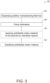
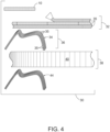
- Fig. 3 includes a flowchart illustrating an example additive manufacturing method 30, and Fig. 4 includes illustrations corresponding and/or relating to example operations of method 30.
- Method 30 includes dispensing 32 additive manufacturing fiber tow 10 according to a configuration of an article 34 ( Fig. 4 ) that is being additively manufactured.
- the additive manufacturing fiber tow 10 may be dispensed in a two- or three-dimensional arrangement corresponding to a configuration of article 34, may be dispensed on one or more forms or jigs or other structures that correspond to the configuration of article 34 or a portion of it, or may be dispensed without a form or jig or other structure that corresponds to the configuration of article 34 or a portion of it.
- the additive manufacturing fiber tow 10 may be dispensed in one or more sequential or successive courses 35 that may be formed and/or may extend along a length individually, and/or multiple courses 35 may be formed partly or completely atop and/or adjacent each other and may be parallel and/or transverse to each other.
- courses 35 may be formed in two-dimensional and/or three-dimensional arrangements that may include any or all of two-dimensional layers or planes, either alone or as successive layers that together provide three-dimensional structures, or as individual courses 35 or groups of courses 35 that may form 2D or 3D chain-link or truss structures, or other structural configurations.
- Method 30 further includes fixing 36 the bindments 16 of the additive manufacturing fiber tow 10 in the configuration of article 34.
- the fixing 36 may include any or all of adhering, bonding, melting, fusing, curing, etc. the bindments 16 to hold or secure them together and/or to elongate fibers 14 to hold additive manufacturing fiber tow 10 in a configuration with a fixed rigidity (e.g., at least a semi-rigidity) that is greater than a rigidity of additive manufacturing fiber tow 10 before the bindments 16 are fixed.
- Fixing 36 also includes maintaining the plural interstitial regions 20 ( Fig. 1 ) that give fiber tow 10 a porous configuration. In examples, sequential or successive courses of the additive manufacturing fiber tow 10 may be fixed together by the bindments 16.
- interstitial regions 20 may change from their original form as a result of fixing 36, while interstitial regions 20 overall remain.
- the bindments 16 may be fixed by one or more of adhesion, fusion, chemical reaction, radiation cure, or intermolecular forces between the bindments 16 and/or between the bindments 16 and the elongate fibers 14.
- elongate fibers 14 may have at least a fiber melting temperature
- bindments 16 e.g., glass
- bindment melting temperature lower than the filament melting temperature
- fixing 36 the bindments 16 of the additive manufacturing fiber tow 10 provides a rigidity that is sufficiently greater than an initial rigidity of additive manufacturing fiber tow 10 and/or elongate fibers 14 to hold additive manufacturing fiber tow 10 in the configuration of article 34.
- the article 34 is a preform (e.g., an uncompleted article of manufacture that is formed or configured with a shape to be completed subsequently).
- article 34 may be or include a preform repair patch that may be applied to, infused with, and solidified on a structure to be repaired.
- Method 30 further may include applying 38 a solidifiable matrix material 40 ( Fig.
- the plural interstitial regions 20 may include plural open spacings or voids among the elongate fibers 14 and the bindments 16. Also in some examples, some or all of the bindments 16 may be soluble in or otherwise able to meld with or dissolve into the solidifiable matrix material 40.
- a "solidifiable matrix material” is a material that is initially not in a solid form (e.g., in a liquid phase or in a similar flowable state) and is configured to be solidified into a solid phase or a similar non-flowable state.
- the solidifiable matrix material may be curable so that the solidifiable matrix material, which may be referred to as a curable, solidifiable matrix material, may be cured as a result of cross-linking of polymer chains, such as responsive to an application of a curing energy.
- solidifying 42 may include applying a curing energy that may comprise one or more of heat, ultraviolet light, visible light, infrared light, x-rays, electron beams, and microwaves, for example.
- Curable, solidifiable matrix materials may take the form of one or more of a polymer, a resin, a thermoset, a photopolymer, an ultraviolet photopolymer, a visible-light photopolymer, an infrared-light photopolymer, and an x-ray photopolymer.
- a photopolymer is a polymer that is configured to be cured in the presence of light, such as one or more of ultraviolet light, visible-light, infrared-light, and x-rays.
- the solidifiable matrix material may be or include a thermoplastic and may be referred to as a thermoplastic solidifiable matrix material, and solidifying 42 may include providing a reduced temperature or other environment in which the thermoplastic matrix material can solidify and/or set.
- Applying 38 the solidifiable matrix material 40 may include, for example, one or more of spraying, coating, misting, infusing, and dripping the additive manufacturing fiber tow with the solidifiable matrix material, or dipping or otherwise inserting article 34 into a bath, reservoir, or other supply of solidifiable matrix material 40.
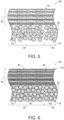
- Fig. 5 is a fragmentary illustration of an example arrangement 46 that may correspond to article 34 (e.g., Fig. 4 , such as a preform according to the claimed invention with fixed bindments 16), which includes interstitial regions 20 available to receive the solidifiable matrix material 40 and courses 35, some of which may be transverse to others.
- Fig. 6 is a fragmentary illustration of example arrangement that may correspond to finished article 44 ( Fig. 4 ) with solidifiable matrix material 40 (indicated by stipple) incorporated into interstitial regions 20.
- An aspect of additive manufacturing fiber tow 10 is that it allows and/or supports manufacture of an article 34, such as a preform, that may be manufactured and stored for subsequent use and application of solidifiable matrix material to form a finished article 44.
- article 34 may be or include a preform repair patch that may be subsequently applied to, infused with, and solidified on a structure to be repaired.
- article 34 may be or include a preform for use to manufacture a finished article or end product/item. As a result, such preforms may be manufactured and stored until needed, which may provide improved functionality of the preform article 34 without a premature application or use of a solidifiable matrix material.
- Figs. 7 and 8 schematically illustrate an elongate additive manufacturing fiber tow 50 in a side view and in cross-section, respectively.
- Additive manufacturing fiber tow 50 includes a bundle 52 of multiple elongate fibers 54 and bindments 56 interposed between, among, and/or on the elongate fibers 54.
- Elongate fibers 54 may be analogous to, or the same as, elongate fibers 14 of Figs. 1 and 2 .
- the bindments 56 may include or be configured as elongated bindment segments among elongate fibers 54.
- the bindments 56 establish among the plural elongate fibers 54 and the bindments 56 plural interstitial regions 58 that give additive manufacturing fiber tow 50 a porous configuration.
- Method 30 of Fig. 3 and the illustrations of Fig. 4 are similarly applicable to additive manufacturing fiber tow 50.
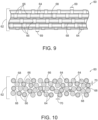
- Figs. 9 and 10 schematically illustrate an elongate additive manufacturing fiber tow 60 in a side view and in cross-section, respectively.
- Additive manufacturing fiber tow 60 includes a bundle 62 of multiple elongate fibers 64 and bindments 66 interposed between, among, and/or on the elongate fibers 64.
- Elongate fibers 64 may be analogous to, or the same as, elongate fibers 14 of Figs. 1 and 2 and elongate fibers 54 of Figs. 7 and 8 .
- the bindments 66 may include or be configured as coating segments on elongate fibers 64.
- the bindments 66 establish among the plural elongate fibers 64 and the bindments 66 plural interstitial regions 68 that give additive manufacturing fiber tow 60 a porous configuration.
- Method 30 of Fig. 3 and the illustrations of Fig. 4 are similarly applicable to additive manufacturing fiber tow 60.
- the bindments 16 may include or be configured as plural particles (e.g., some or all of which may have generally unitary aspect ratios, i.e., having generally equal dimensions in transverse directions).
- the bindments 56 may include or be configured as plural elongated bindment segments (e.g., which may have elongated lengths 67, but are generally shorter than elongate fibers 54, and so are "segmented").
- the bindments 66 may include or be configured as coatings on the elongate fibers 64 with lengths 69 less than the lengths of elongate fibers 64.
- Elongate fibers 14, 54, and 64 may be generally of filament diameter 24.
- the bindments 16, 56, and 66 may be generally of a bindment thickness 70 (e.g., diameter) that is less than or equal to twice the filament diameter 24. In other examples, the bindment thickness 70 is less than or equal to the filament diameter 24, and in still other examples, bindment thickness 70 is less than or equal to 25 percent of the filament diameter 24. In additive manufacturing fiber tows 50 and 60, for example, respective lengths 67 and 69 of segmental bindments 56 and 66 may be at least 0.5 times, or as much as 1,000 times greater than bindment thickness 70.
- bindments 16, 56, and 66 may include, comprise, or be formed of one or more of a thermoplastic, an adhesive, a metal, a glass, and/or a catalyst or a reactive component of the solidifiable matrix material 40.
- elongate fibers 14, 54, and 64 may include, comprise, or be formed of one or more of carbon fibers, glass fibers, aramid fibers, boron fibers, silicon-carbide fibers, ceramic fibers, optical fibers, fiber bundles, fiber weaves, fiber braids, wires, metal wires, conductive wire, and wire bundles.
- bindments 16, 56, and 66 are of one or more materials that are different from the one or more materials of respective elongate fibers 14, 54, and 64. Also in some examples, some of bindments 16, 56, and 66 of respective elongate additive manufacturing fiber tows 10, 50, and 60 are of at least one material that is soluble in or otherwise able to meld with or dissolve into the solidifiable matrix material 40, while others of the respective bindments 16, 56, and 66 are of at least one material that is not soluble in or otherwise able to meld with or dissolve into the solidifiable matrix material 40.
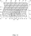
- FIG. 11 schematically illustrates a sectional side view of multiple elongate additive manufacturing fiber tows 80 and 81 that are fixed together adjacent each other as respective courses in an article 82.
- Each of additive manufacturing fiber tows 80 and 81 includes a bundle 84 of multiple elongate fibers 86 and one or more bindments 88 that encircle (e.g., spirally) bundle 84 of multiple elongate fibers 86.
- elongate additive manufacturing fiber tow 81 further includes one or more bindments 87 that encircle (e.g., spirally) one or more subsets (e.g., two shown) of multiple elongate fibers 86 within elongate additive manufacturing fiber tow 81.
- Bindments 87 establish around the subsets of elongate fibers 86 that are encircled by the bindments 87, and the adjacent elongate fibers 86, interstitial regions 89 that give additive manufacturing fiber tow 81 a porous configuration.
- Bindments 87 and 88 additionally or alternatively may be described as encircling bindments.
- bindments 88 may be continuous bindments that extend a full length, or substantially a full length, of a corresponding fiber tow. Additionally or alternatively, in some examples, bindments 87 and 88 may be segmented bindments that extend only a portion of a corresponding fiber tow.
- one or more of additive manufacturing fiber tows 80 and 81 further may include bindments interposed between, among, and/or on the elongate fibers 86, as described hereinabove.
- Elongate fibers 86 may be analogous to, or the same as, elongate fibers 14 of Figs. 1 and 2 , elongate fibers 54 of Figs. 7 and 8 , and elongate fibers 64 of Figs. 9 and 10 .
- the Bindments 88 establish between the adjacent additive manufacturing fiber tows 80 and/or 81 plural inter-course interstitial regions 90 (i.e., open spacings and/or voids) that give article 82 a porous configuration, at least when in a preform configuration prior to solidifiable matrix material 40 being received within the plural inter-course interstitial regions 90.
- the bindments 87 and 88 may be fixed with the plural elongate fibers 86 to hold additive manufacturing fiber tows 80 and/or 81 in a configuration at least semi-rigidly while maintaining the inter-course interstitial regions 90 and/or the interstitial regions 89.
- the bindments 88 may include or be configured as coating segments on additive manufacturing fiber tows 80. Method 30 of Fig. 3 and the illustrations of Fig. 4 are similarly applicable to additive manufacturing fiber tows 80.
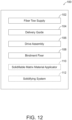
- Fig. 12 is a block diagram of a system 100 for additively manufacturing an article.
- System 100 includes a supply 102 of the additive manufacturing fiber tow, which may include any of additive manufacturing fiber tows 10, 50, 60, and/or 80, for example.
- a delivery guide 104 is positioned to receive the additive manufacturing fiber tow from the supply 102 and configured to dispense the additive manufacturing fiber tow to additively manufacture the article.
- a drive assembly 106 is operatively coupled to the delivery guide 104 and configured to selectively move the delivery guide 104 in two- or three-dimensions to additively manufacture the article.
- a bindment fixer 108 is configured to rigidly fix the bindments of the additive manufacturing fiber tow with the plural elongate fibers.
- a solidifiable matrix material applicator 110 applies solidifiable matrix material to the article, and a solidifying system 112 solidifies the solidifiable matrix material.
- Bindment fixer 108 may be configured to perform one or more operations as described with reference to fixing 36 ( Fig. 3 ) of method 30 ( Fig. 3 ). In some examples, bindment fixer 108 may be configured to provide one or more of adhesion, fusion, chemical reaction, radiation cure, or intermolecular forces between the bindments of an additive manufacturing fiber tow, as described herein. Solidifiable matrix material applicator 110 may be configured to perform one or more operations as described with reference to applying 38 ( Fig. 3 ) the solidifiable matrix material of method 30 ( Fig. 3 ).
- solidifiable matrix material applicator 110 may be configured to provide one or more one or more of spraying, coating, misting, infusing, and dripping the additive manufacturing fiber tow with the solidifiable matrix material, or dipping or otherwise inserting an article into a bath, reservoir, or other supply of solidifiable matrix material.
- solidifying system 112 may be configured to perform one or more operations as described with reference to solidifying 42 ( Fig. 3 ) the solidifiable matrix material of method 30 ( Fig. 3 ).
- solidifying system 112 may be configured to apply a curing energy that may comprise one or more of heat, ultraviolet light, visible light, infrared light, x-rays, electron beams, and microwaves, and in other examples solidifying system 112 may be configured to provide a reduced temperature or environment in which a solidifiable matrix material can solidify and/or set.
- a curing energy may comprise one or more of heat, ultraviolet light, visible light, infrared light, x-rays, electron beams, and microwaves
- solidifying system 112 may be configured to provide a reduced temperature or environment in which a solidifiable matrix material can solidify and/or set.
- fixing 36 the bindments of the additive manufacturing fiber tow 10 provides a rigidity that is sufficiently greater than an initial rigidity of additive manufacturing fiber tow 10 and/or elongate fibers 14 to hold additive manufacturing fiber tow 10 in the configuration of article 34.
- the article 34 is a preform (e.g., an uncompleted article of manufacture that is formed or configured with a shape to be completed subsequently).
- article 34 may be or include a preform repair patch that may be applied to, infused with, and solidified on a structure to be repaired.
- Method 30 further may include applying 38 a solidifiable matrix material 40 ( Fig.
- the plural interstitial regions 20 may include plural open spacings among the elongate fibers 14 and the bindments. Also in some examples, some or all of the bindments may be soluble in or otherwise able to meld with (e.g., dissolve into) the solidifiable matrix material 40.
- the terms “adapted” and “configured” mean that the element, component, or other subject matter is designed and/or intended to perform a given function. Thus, the use of the terms “adapted” and “configured” should not be construed to mean that a given element, component, or other subject matter is simply “capable of” performing a given function but that the element, component, and/or other subject matter is specifically selected, created, implemented, utilized, programmed, and/or designed for the purpose of performing the function. It is also within the scope of the present disclosure that elements, components, and/or other recited subject matter that is recited as being adapted to perform a particular function may additionally or alternatively be described as being configured to perform that function, and vice versa. Similarly, subject matter that is recited as being configured to perform a particular function may additionally or alternatively be described as being operative to perform that function.
- the term "and/or" placed between a first entity and a second entity means one of (1) the first entity, (2) the second entity, and (3) the first entity and the second entity.
- Multiple entries listed with “and/or” should be construed in the same manner, i.e., "one or more" of the entities so conjoined.
- Other entities optionally may be present other than the entities specifically identified by the "and/or” clause, whether related or unrelated to those entities specifically identified.
- a reference to "A and/or B,” when used in conjunction with open-ended language such as “comprising,” may refer, in one example, to A only (optionally including entities other than B); in another example, to B only (optionally including entities other than A); in yet another example, to both A and B (optionally including other entities).
- These entities may refer to elements, actions, structures, steps, operations, values, and the like.
Landscapes
- Engineering & Computer Science (AREA)
- Chemical & Material Sciences (AREA)
- Mechanical Engineering (AREA)
- Composite Materials (AREA)
- Materials Engineering (AREA)
- Manufacturing & Machinery (AREA)
- Textile Engineering (AREA)
- Physics & Mathematics (AREA)
- Optics & Photonics (AREA)
- Robotics (AREA)
- Ceramic Engineering (AREA)
- Civil Engineering (AREA)
- Structural Engineering (AREA)
- Moulding By Coating Moulds (AREA)
Description
- The present disclosure relates to fiber tows for additive manufacturing.
- Additive manufacturing may include a 3D printing process that uses a continuous filament that is dispensed or extruded from a dispenser or print head that moves in two- or three-dimensions under computer control to manufacture an article. Current additive manufacturing systems "print" articles by sequentially or successively laying down layers on top of and/or beside each other. In some examples, the continuous filament is comprised of a curable material such as a resin or polymer that is cured during the additive manufacturing process.
-
WO 2016/147646 relates to a sheet-shaped reinforced fiber substrate that produces a less waste in manufacturing a fiber reinforced plastic molded article and reduces a positional deviation of a reinforced fiber substrate for reinforcement; a preform; and a fiber reinforced plastic molded article. The sheet-shaped reinforced fiber substrate comprises bundles of reinforced fibers aligned with longitudinal directions thereof set in one direction, the positions of the adjacent bundles of reinforced fibers being constrained to each other to keep a sheet-shaped form. The sheet-shaped reinforced fiber substrate is characterized in that, in the sheet-shaped reinforced fiber substrate, a distribution amount of the reinforced fibers is partially increased and a weight of the distributed reinforced fibers per unit area is non-uniform. -
US 2017/0173868 A1 relates to 3D printing of a combined continuous/random fiber reinforced composite filament including a plurality of axial fiber strands extending substantially continuously within a matrix material of the fiber reinforced composite filament as well as a multiplicity of short chopped fiber rods extending at least in part randomly within the same matrix material via a deposition head including a conduit continuously transitioning to a substantially rounded outlet tipped with an ironing lip, which is driven to flatten the fiber reinforced composite filament against previously deposited portions of the part, as the matrix material and included therein a first proportion of the short chopped fiber rods are is flowed interstitially among the axial fiber strands spread by the ironing lip. -
US2008/020193A1 relates to a hybrid fibre tow that can be used in freeform fabrication. - A method of additively manufacturing according to claim 1 and an additive manufacturing preform according to claim 5 are disclosed.
- Additive manufacturing fiber tows comprise a bundle of elongate fibers. Bindments, which may include particles, elongated bindment segments, coating segments, and/or encircling bindments are interposed among the plural elongate fibers to provide interstitial regions among the plural elongate fibers and the bindments.
- Methods of additively manufacturing an article with a configuration comprise dispensing the additive manufacturing fiber tow with bindments in multiple successive courses in the configuration to additively manufacture the article. The methods may include fixing the bindments together to hold the article in the configuration with the interstitial regions among the plural elongate fibers and the bindments. A solidifiable matrix material may be applied to the article, including to the interstitial regions, and the solidifiable matrix material may be solidified to form a finished article. Some systems for additively manufacturing a part comprise a supply of additive manufacturing fiber tow with bindments and a delivery guide positioned to receive the fiber tow from the supply and to dispense the additive manufacturing fiber tow with bindments to additively manufacture the article.
-
-
Fig. 1 is a schematic side view of an elongate additive manufacturing fiber tow. -
Fig. 2 is a schematic cross sectional view of the elongate additive manufacturing fiber tow ofFig. 1 . -
Fig. 3 includes a flowchart illustrating an example additive manufacturing method. -
Fig. 4 includes illustrations corresponding to example operations of the method ofFig. 3 . -
Fig. 5 is a fragmentary illustration of an example arrangement that may correspond to an article with interstitial regions available to receive a solidifiable matrix material. -
Fig. 6 is a fragmentary illustration of the article ofFig. 5 with solidifiable matrix material (indicated by stipple) incorporated into the interstitial regions. -
Fig. 7 schematically illustrates an alternative example of an elongate additive manufacturing fiber tow in a side view. -
Fig. 8 schematically illustrates the alternative example of an elongate additive manufacturing fiber tow ofFig. 7 in cross-section. -
Fig. 9 schematically illustrates another alternative example of an elongate additive manufacturing fiber tow in a side view. -
Fig. 10 schematically illustrates the alternative example of an elongate additive manufacturing fiber tow ofFig. 9 in cross-section. -
Fig. 11 schematically illustrates a sectional side view of still another example of elongate additive manufacturing fiber tows that are fixed together as part of a composite or multi-course article. -
Fig. 12 is a schematic illustration representing a system for additive manufacturing that utilize multi-part filaments. - Additive manufacturing fiber tows and related systems and methods are disclosed herein. Generally, in the figures, elements that are likely to be included in a given example are illustrated in solid lines, while elements that are optional to a given example are illustrated in broken lines. However, elements that are illustrated in solid lines are not essential to all examples of the present disclosure, and an element shown in solid lines may be omitted from a particular example without departing from the scope of the present invention as defined by the appended claims.
- As schematically illustrated in
Figs. 1 and 2 an elongate additivemanufacturing fiber tow 10 is shown in a side view and in cross-section, respectively. Elongate additivemanufacturing fiber tow 10 additionally or alternatively may be referred to asadditive manufacturing tow 10 orfiber tow 10.Fiber tow 10 includes abundle 12 of multipleelongate fibers 14 andbindments 16 interposed between, among, and/or on theelongate fibers 14. Thebindments 16 may take any suitable form or structure, such as including or being configured as particles, as illustrated inFigs. 1 and 2 . Other illustrative, non-exclusive configurations ofbindments 16 are described below in greater detail. Thebindments 16 may be characterized in that they are distinct from the pluralelongate fibers 14 and establish among the pluralelongate fibers 14 and thebindments 16 plural interstitial regions 20 (e.g., open spacings and/or voids) that give fiber tow 10 a porous configuration, and further that thebindments 16 may be fixed together and with the pluralelongate fibers 14 to hold additive manufacturing fiber tow 10 in a configuration at least semi-rigidly while maintaining the pluralinterstitial regions 20. In examples in whichbindments 16 do not extend a full length of afiber tow 10, and in which a plurality ofbindments 16 are utilized, thebindments 16 may be described as segmented bindments. - The
elongate fibers 14 typically, or at least in their initially manufactured form, havelengths 22 that are significantly greater than theirdiameters 24. (Diameter 24 herein refers to a sectional, lateral dimension through a center of a body and does not imply or require that the body have a circular cross section. Elongatefibers 14 have cross sections that may be circular or non-circular.) As illustrative, non-exclusive examples, theelongate fibers 14 each may have alength 22 that is at least 10, at least 100, at least 1,000, at least 10,000, at least 100,000, or at least 1,000,000 times greater than itsdiameter 24. In accordance with these examples, theelongate fibers 14 may be referred to as being continuous or chopped. Additivemanufacturing fiber tow 10 is configured for use as a feedstock, or at least as a component of a feedstock, for an additive manufacturing system, such as may be referred to as a 3-D printer or a fused filament fabrication (FFF) system, for example. -
Fig. 3 includes a flowchart illustrating an exampleadditive manufacturing method 30, andFig. 4 includes illustrations corresponding and/or relating to example operations ofmethod 30. -
Method 30 includes dispensing 32 additivemanufacturing fiber tow 10 according to a configuration of an article 34 (Fig. 4 ) that is being additively manufactured. As examples, the additivemanufacturing fiber tow 10 may be dispensed in a two- or three-dimensional arrangement corresponding to a configuration ofarticle 34, may be dispensed on one or more forms or jigs or other structures that correspond to the configuration ofarticle 34 or a portion of it, or may be dispensed without a form or jig or other structure that corresponds to the configuration ofarticle 34 or a portion of it. As further examples, the additivemanufacturing fiber tow 10 may be dispensed in one or more sequential orsuccessive courses 35 that may be formed and/or may extend along a length individually, and/ormultiple courses 35 may be formed partly or completely atop and/or adjacent each other and may be parallel and/or transverse to each other. In examples,courses 35 may be formed in two-dimensional and/or three-dimensional arrangements that may include any or all of two-dimensional layers or planes, either alone or as successive layers that together provide three-dimensional structures, or asindividual courses 35 or groups ofcourses 35 that may form 2D or 3D chain-link or truss structures, or other structural configurations. -
Method 30 further includes fixing 36 thebindments 16 of the additivemanufacturing fiber tow 10 in the configuration ofarticle 34. Thefixing 36 may include any or all of adhering, bonding, melting, fusing, curing, etc. thebindments 16 to hold or secure them together and/or toelongate fibers 14 to hold additivemanufacturing fiber tow 10 in a configuration with a fixed rigidity (e.g., at least a semi-rigidity) that is greater than a rigidity of additivemanufacturing fiber tow 10 before thebindments 16 are fixed.Fixing 36 also includes maintaining the plural interstitial regions 20 (Fig. 1 ) that give fiber tow 10 a porous configuration. In examples, sequential or successive courses of the additivemanufacturing fiber tow 10 may be fixed together by thebindments 16. In some examples,interstitial regions 20 may change from their original form as a result of fixing 36, whileinterstitial regions 20 overall remain. As examples, thebindments 16 may be fixed by one or more of adhesion, fusion, chemical reaction, radiation cure, or intermolecular forces between thebindments 16 and/or between thebindments 16 and theelongate fibers 14. In some examples,elongate fibers 14 may have at least a fiber melting temperature, and bindments 16 (e.g., glass) may have a bindment melting temperature lower than the filament melting temperature, so thatfixing 36 may includemelting bindments 16 to adhere them together. - In some examples, fixing 36 the
bindments 16 of the additivemanufacturing fiber tow 10 provides a rigidity that is sufficiently greater than an initial rigidity of additivemanufacturing fiber tow 10 and/orelongate fibers 14 to hold additivemanufacturing fiber tow 10 in the configuration ofarticle 34. According to the claimed invention thearticle 34 is a preform (e.g., an uncompleted article of manufacture that is formed or configured with a shape to be completed subsequently). For example,article 34 may be or include a preform repair patch that may be applied to, infused with, and solidified on a structure to be repaired.Method 30 further may include applying 38 a solidifiable matrix material 40 (Fig. 4 ) toarticle 34 to be received by theinterstitial regions 20, and solidifying 42 of thesolidifiable matrix material 40 to form a finishedarticle 44. In some examples, the pluralinterstitial regions 20 may include plural open spacings or voids among theelongate fibers 14 and thebindments 16. Also in some examples, some or all of thebindments 16 may be soluble in or otherwise able to meld with or dissolve into thesolidifiable matrix material 40. - As used herein, a "solidifiable matrix material" is a material that is initially not in a solid form (e.g., in a liquid phase or in a similar flowable state) and is configured to be solidified into a solid phase or a similar non-flowable state. In some examples, the solidifiable matrix material may be curable so that the solidifiable matrix material, which may be referred to as a curable, solidifiable matrix material, may be cured as a result of cross-linking of polymer chains, such as responsive to an application of a curing energy. In some examples employing such a curable, solidifiable matrix material, solidifying 42 may include applying a curing energy that may comprise one or more of heat, ultraviolet light, visible light, infrared light, x-rays, electron beams, and microwaves, for example. Curable, solidifiable matrix materials may take the form of one or more of a polymer, a resin, a thermoset, a photopolymer, an ultraviolet photopolymer, a visible-light photopolymer, an infrared-light photopolymer, and an x-ray photopolymer. As used herein, a photopolymer is a polymer that is configured to be cured in the presence of light, such as one or more of ultraviolet light, visible-light, infrared-light, and x-rays. In other examples, the solidifiable matrix material may be or include a thermoplastic and may be referred to as a thermoplastic solidifiable matrix material, and solidifying 42 may include providing a reduced temperature or other environment in which the thermoplastic matrix material can solidify and/or set. Applying 38 the
solidifiable matrix material 40 may include, for example, one or more of spraying, coating, misting, infusing, and dripping the additive manufacturing fiber tow with the solidifiable matrix material, or dipping or otherwise insertingarticle 34 into a bath, reservoir, or other supply ofsolidifiable matrix material 40. -
Fig. 5 is a fragmentary illustration of anexample arrangement 46 that may correspond to article 34 (e.g.,Fig. 4 , such as a preform according to the claimed invention with fixed bindments 16), which includesinterstitial regions 20 available to receive thesolidifiable matrix material 40 andcourses 35, some of which may be transverse to others.Fig. 6 is a fragmentary illustration of example arrangement that may correspond to finished article 44 (Fig. 4 ) with solidifiable matrix material 40 (indicated by stipple) incorporated intointerstitial regions 20. - An aspect of additive
manufacturing fiber tow 10 is that it allows and/or supports manufacture of anarticle 34, such as a preform, that may be manufactured and stored for subsequent use and application of solidifiable matrix material to form afinished article 44. As described hereinabove, for example,article 34 may be or include a preform repair patch that may be subsequently applied to, infused with, and solidified on a structure to be repaired. In other examples,article 34 may be or include a preform for use to manufacture a finished article or end product/item. As a result, such preforms may be manufactured and stored until needed, which may provide improved functionality of thepreform article 34 without a premature application or use of a solidifiable matrix material. - As an alternative example,
Figs. 7 and 8 schematically illustrate an elongate additivemanufacturing fiber tow 50 in a side view and in cross-section, respectively. Additivemanufacturing fiber tow 50 includes abundle 52 of multipleelongate fibers 54 andbindments 56 interposed between, among, and/or on theelongate fibers 54.Elongate fibers 54 may be analogous to, or the same as,elongate fibers 14 ofFigs. 1 and 2 . Thebindments 56 may include or be configured as elongated bindment segments amongelongate fibers 54. Thebindments 56 establish among the pluralelongate fibers 54 and thebindments 56 pluralinterstitial regions 58 that give additive manufacturing fiber tow 50 a porous configuration.Method 30 ofFig. 3 and the illustrations ofFig. 4 are similarly applicable to additivemanufacturing fiber tow 50. - As another alternative example,
Figs. 9 and 10 schematically illustrate an elongate additivemanufacturing fiber tow 60 in a side view and in cross-section, respectively. Additivemanufacturing fiber tow 60 includes abundle 62 of multipleelongate fibers 64 andbindments 66 interposed between, among, and/or on theelongate fibers 64.Elongate fibers 64 may be analogous to, or the same as,elongate fibers 14 ofFigs. 1 and 2 andelongate fibers 54 ofFigs. 7 and 8 . Thebindments 66 may include or be configured as coating segments onelongate fibers 64. Thebindments 66 establish among the pluralelongate fibers 64 and thebindments 66 pluralinterstitial regions 68 that give additive manufacturing fiber tow 60 a porous configuration.Method 30 ofFig. 3 and the illustrations ofFig. 4 are similarly applicable to additivemanufacturing fiber tow 60. - As examples, the
bindments 16 may include or be configured as plural particles (e.g., some or all of which may have generally unitary aspect ratios, i.e., having generally equal dimensions in transverse directions). Thebindments 56 may include or be configured as plural elongated bindment segments (e.g., which may have elongatedlengths 67, but are generally shorter thanelongate fibers 54, and so are "segmented"). Thebindments 66 may include or be configured as coatings on theelongate fibers 64 withlengths 69 less than the lengths ofelongate fibers 64.Elongate fibers filament diameter 24. Thebindments filament diameter 24. In other examples, thebindment thickness 70 is less than or equal to thefilament diameter 24, and in still other examples,bindment thickness 70 is less than or equal to 25 percent of thefilament diameter 24. In additive manufacturing fiber tows 50 and 60, for example,respective lengths bindment thickness 70. - As examples, bindments 16, 56, and 66 may include, comprise, or be formed of one or more of a thermoplastic, an adhesive, a metal, a glass, and/or a catalyst or a reactive component of the
solidifiable matrix material 40. As illustrative, non-exclusive examples,elongate fibers elongate fibers bindments solidifiable matrix material 40, while others of therespective bindments solidifiable matrix material 40. - As another alternative example,
Fig. 11 schematically illustrates a sectional side view of multiple elongate additive manufacturing fiber tows 80 and 81 that are fixed together adjacent each other as respective courses in anarticle 82. Each of additive manufacturing fiber tows 80 and 81 includes abundle 84 of multipleelongate fibers 86 and one or more bindments 88 that encircle (e.g., spirally) bundle 84 of multipleelongate fibers 86. As an example, elongate additivemanufacturing fiber tow 81 further includes one or more bindments 87 that encircle (e.g., spirally) one or more subsets (e.g., two shown) of multipleelongate fibers 86 within elongate additivemanufacturing fiber tow 81.Bindments 87 establish around the subsets ofelongate fibers 86 that are encircled by thebindments 87, and the adjacentelongate fibers 86,interstitial regions 89 that give additive manufacturing fiber tow 81 a porous configuration. Bindments 87 and 88 additionally or alternatively may be described as encircling bindments. In some examples, bindments 88 may be continuous bindments that extend a full length, or substantially a full length, of a corresponding fiber tow. Additionally or alternatively, in some examples, bindments 87 and 88 may be segmented bindments that extend only a portion of a corresponding fiber tow. - In some examples, one or more of additive manufacturing fiber tows 80 and 81 further may include bindments interposed between, among, and/or on the
elongate fibers 86, as described hereinabove.Elongate fibers 86 may be analogous to, or the same as,elongate fibers 14 ofFigs. 1 and 2 ,elongate fibers 54 ofFigs. 7 and 8 , andelongate fibers 64 ofFigs. 9 and 10 . TheBindments 88 establish between the adjacent additive manufacturing fiber tows 80 and/or 81 plural inter-course interstitial regions 90 (i.e., open spacings and/or voids) that give article 82 a porous configuration, at least when in a preform configuration prior tosolidifiable matrix material 40 being received within the plural inter-courseinterstitial regions 90. In examples, thebindments elongate fibers 86 to hold additive manufacturing fiber tows 80 and/or 81 in a configuration at least semi-rigidly while maintaining the inter-courseinterstitial regions 90 and/or theinterstitial regions 89. In some examples, thebindments 88 may include or be configured as coating segments on additivemanufacturing fiber tows 80.Method 30 ofFig. 3 and the illustrations ofFig. 4 are similarly applicable to additivemanufacturing fiber tows 80. -
Fig. 12 is a block diagram of asystem 100 for additively manufacturing an article.System 100 includes asupply 102 of the additive manufacturing fiber tow, which may include any of additive manufacturing fiber tows 10, 50, 60, and/or 80, for example. Adelivery guide 104 is positioned to receive the additive manufacturing fiber tow from thesupply 102 and configured to dispense the additive manufacturing fiber tow to additively manufacture the article. Adrive assembly 106 is operatively coupled to thedelivery guide 104 and configured to selectively move thedelivery guide 104 in two- or three-dimensions to additively manufacture the article. Abindment fixer 108 is configured to rigidly fix the bindments of the additive manufacturing fiber tow with the plural elongate fibers. In some examples, a solidifiablematrix material applicator 110 applies solidifiable matrix material to the article, and a solidifyingsystem 112 solidifies the solidifiable matrix material. -
Bindment fixer 108 may be configured to perform one or more operations as described with reference to fixing 36 (Fig. 3 ) of method 30 (Fig. 3 ). In some examples,bindment fixer 108 may be configured to provide one or more of adhesion, fusion, chemical reaction, radiation cure, or intermolecular forces between the bindments of an additive manufacturing fiber tow, as described herein. Solidifiablematrix material applicator 110 may be configured to perform one or more operations as described with reference to applying 38 (Fig. 3 ) the solidifiable matrix material of method 30 (Fig. 3 ). In some examples, solidifiablematrix material applicator 110 may be configured to provide one or more one or more of spraying, coating, misting, infusing, and dripping the additive manufacturing fiber tow with the solidifiable matrix material, or dipping or otherwise inserting an article into a bath, reservoir, or other supply of solidifiable matrix material. Likewise, solidifyingsystem 112 may be configured to perform one or more operations as described with reference to solidifying 42 (Fig. 3 ) the solidifiable matrix material of method 30 (Fig. 3 ). In some examples, solidifyingsystem 112 may be configured to apply a curing energy that may comprise one or more of heat, ultraviolet light, visible light, infrared light, x-rays, electron beams, and microwaves, and in otherexamples solidifying system 112 may be configured to provide a reduced temperature or environment in which a solidifiable matrix material can solidify and/or set. - According to the claimed invention, fixing 36 the bindments of the additive
manufacturing fiber tow 10 provides a rigidity that is sufficiently greater than an initial rigidity of additivemanufacturing fiber tow 10 and/orelongate fibers 14 to hold additivemanufacturing fiber tow 10 in the configuration ofarticle 34. According to the claimed invention thearticle 34 is a preform (e.g., an uncompleted article of manufacture that is formed or configured with a shape to be completed subsequently). For example,article 34 may be or include a preform repair patch that may be applied to, infused with, and solidified on a structure to be repaired.Method 30 further may include applying 38 a solidifiable matrix material 40 (Fig. 3 ) toarticle 34 to be received by theinterstitial regions 20, and solidifying 42 of thesolidifiable matrix material 40 to form afinished article 44. In some examples, the pluralinterstitial regions 20 may include plural open spacings among theelongate fibers 14 and the bindments. Also in some examples, some or all of the bindments may be soluble in or otherwise able to meld with (e.g., dissolve into) thesolidifiable matrix material 40. - As used herein, the terms "adapted" and "configured" mean that the element, component, or other subject matter is designed and/or intended to perform a given function. Thus, the use of the terms "adapted" and "configured" should not be construed to mean that a given element, component, or other subject matter is simply "capable of" performing a given function but that the element, component, and/or other subject matter is specifically selected, created, implemented, utilized, programmed, and/or designed for the purpose of performing the function. It is also within the scope of the present disclosure that elements, components, and/or other recited subject matter that is recited as being adapted to perform a particular function may additionally or alternatively be described as being configured to perform that function, and vice versa. Similarly, subject matter that is recited as being configured to perform a particular function may additionally or alternatively be described as being operative to perform that function.
- As used herein, the term "and/or" placed between a first entity and a second entity means one of (1) the first entity, (2) the second entity, and (3) the first entity and the second entity. Multiple entries listed with "and/or" should be construed in the same manner, i.e., "one or more" of the entities so conjoined. Other entities optionally may be present other than the entities specifically identified by the "and/or" clause, whether related or unrelated to those entities specifically identified. Thus, as a non-limiting example, a reference to "A and/or B," when used in conjunction with open-ended language such as "comprising," may refer, in one example, to A only (optionally including entities other than B); in another example, to B only (optionally including entities other than A); in yet another example, to both A and B (optionally including other entities). These entities may refer to elements, actions, structures, steps, operations, values, and the like.
Claims (14)
- A method of additively manufacturing a fiber preform article (34), comprising:dispensing (32) an additive manufacturing fiber tow (10,50,60,80) in a fiber preform article (34) configuration, the additive manufacturing fiber tow (10,50,60,80) including a bundle (12,52,62,84) of plural elongate fibers (14,54,64,86) and bindments (16,56,66,88) interposed among the plural elongate fibers (14,54,64,86), the bindments (16,56,66,88) establishing plural interstitial regions (20,58,68,89,90) among the plural elongate fibers (14,54,64,86); andfixing (36) the bindments (16,56,66,88) with the elongate fibers to hold the additive manufacturing fiber tow (10,50,60,80) in the fiber preform article (34) configuration with the plural interstitial regions (20,58,68,89,90) among the plural elongate fibers (14,54,64,86).
- The method of claim 1 further comprising fixing the bindments (16,56,66,88) using a solidifiable matrix material (40) disposed among the plural elongate fibers (14,54,64,86).
- The method of any of claims 1 to 2, wherein:dispensing (32) the additive manufacturing fiber tow (10,50,60,80) includes dispensing the additive manufacturing fiber tow (10,50,60,80) in plural successive courses of additive manufacturing fiber tow (10,50,60,80); andfixing (36) the bindments (16,56,66,88) with the elongate fibers includes fixing together the bindments (16,56,66,88) of the plural successive courses of additive manufacturing fiber tow (10,50,60,80).
- The method of any of claims 1 to 3 further comprising:applying (38) a solidifiable matrix material (40) to the fiber preform article (34), including applying the solidifiable matrix material (40) to the plural interstitial regions (20,58,68,89,90); andsolidifying (42) the solidifiable matrix material (40).
- An additive manufacturing fiber preform article manufactured according to the method of claim 1, comprising an additive manufacturing fiber tow (10,50,60,80) dispensed in a preform article configuration, the additive manufacturing fiber tow (10,50,60,80) comprising:a bundle (12,52,62,84) of plural elongate fibers (14,54,64,86) of a first rigidity; andbindments (16,56,66,88) interposed among the plural elongate fibers (14,54,64,86) to provide a second rigidity greater than the first rigidity to hold the additive manufacturing fiber tow (10,50,60,80) in the preform article configuration, the bindments (16,56,66,88) establishing plural interstitial regions (20,58,68,89,90) among the plural elongate fibers (14,54,64,86) and the bindments (16,56,66,88) to receive a solidifiable matrix material (40) among the plural elongate fibers (14, 54, 64, 86) of the fiber preform article.
- The additive manufacturing fiber preform of claim 5, wherein at least some of the bindments (16,56,66,88) are configured to be soluble in the solidifiable matrix material (40).
- The additive manufacturing fiber preform of any of claims 5 to 6, wherein some of the bindments (16,56,66,88) are configured to be soluble in the solidifiable matrix material (40) and others of the bindments (16,56,66,88), are configured for not being soluble in the solidifiable matrix material (40).
- The additive manufacturing fiber preform of any of claims 5 to 7, wherein the bindments (16,56,66,88) include plural particles that have generally unitary aspect ratios.
- The additive manufacturing fiber preform of any of claims 5 to 8, wherein the bindments (16,56,66,88) include plural elongated bindment segments.
- The additive manufacturing fiber preform of any of claims 5 to 9, wherein the bindments (16,56,66,88) include plural coating segments on the plural elongate fibers (14,54,64,86).
- The additive manufacturing fiber preform of any of claims 5 to 10, wherein the plural elongate fibers (14,54,64,86) are generally of a filament diameter (24) and the bindments (16,56,66,88) are generally of or less than a bindment segment diameter that is less than or equal to the filament diameter (24).
- The additive manufacturing fiber preform of any of claims 5 to 11, wherein the bindment segment diameter is less than or equal to 25 percent of the filament diameter (24).
- The additive manufacturing fiber preform of any of claims 5 to 12, wherein the plural elongate fibers (14,54,64,86) are of one or more filament materials and the bindments (16,56,66,88) are of one or more bindment materials that are different from the filament materials.
- The additive manufacturing fiber preform of any of claims 5 to 13, wherein the plural elongate fibers (14,54,64,86) include a subset of plural elongate fibers (14,54,64,86) and plural other adjacent elongate fibers (14,54,64,86), and the bindments (16,56,66,88) include encircling bindments (16,56,66,88) that encircle the subset of plural elongate fibers (14,54,64,86) and establish the plural interstitial regions (20,58,68,89,90) between the subset of elongate fibers and the other adjacent elongate fibers (14,54,64,86).
Applications Claiming Priority (1)
| Application Number | Priority Date | Filing Date | Title |
|---|---|---|---|
| US15/675,244 US20190047209A1 (en) | 2017-08-11 | 2017-08-11 | Additive manufacturing fiber tows with bindments and related systems and methods |
Publications (2)
| Publication Number | Publication Date |
|---|---|
| EP3441212A1 EP3441212A1 (en) | 2019-02-13 |
| EP3441212B1 true EP3441212B1 (en) | 2023-11-01 |
Family
ID=62386086
Family Applications (1)
| Application Number | Title | Priority Date | Filing Date |
|---|---|---|---|
| EP18174248.7A Active EP3441212B1 (en) | 2017-08-11 | 2018-05-25 | Additive manufacturing fiber preform article |
Country Status (3)
| Country | Link |
|---|---|
| US (1) | US20190047209A1 (en) |
| EP (1) | EP3441212B1 (en) |
| IL (1) | IL259272B (en) |
Citations (3)
| Publication number | Priority date | Publication date | Assignee | Title |
|---|---|---|---|---|
| US5936861A (en) * | 1997-08-15 | 1999-08-10 | Nanotek Instruments, Inc. | Apparatus and process for producing fiber reinforced composite objects |
| US20080020193A1 (en) * | 2006-07-24 | 2008-01-24 | Jang Bor Z | Hybrid fiber tows containning both nano-fillers and continuous fibers, hybrid composites, and their production processes |
| US20150158246A1 (en) * | 2013-12-10 | 2015-06-11 | Impossible Objects Llc | Tow Stabilization Method and Apparatus |
Family Cites Families (7)
| Publication number | Priority date | Publication date | Assignee | Title |
|---|---|---|---|---|
| WO1997042004A1 (en) * | 1996-05-03 | 1997-11-13 | Minnesota Mining And Manufacturing Company | Method of making a porous abrasive article |
| AU2003262050B2 (en) * | 2002-11-14 | 2009-07-02 | Toray Industries, Inc. | Reinforcing fiber substrate, composite material and method for producing the same |
| WO2014077848A1 (en) * | 2012-11-19 | 2014-05-22 | Hewlett-Packard Development Company, L.P. | Compositions for three-dimensional (3d) printing |
| US20170173868A1 (en) * | 2013-03-22 | 2017-06-22 | Markforged, Inc. | Continuous and random reinforcement in a 3d printed part |
| US10259160B2 (en) * | 2013-03-22 | 2019-04-16 | Markforged, Inc. | Wear resistance in 3D printing of composites |
| EP3272488B1 (en) * | 2015-03-19 | 2020-05-06 | Toray Industries, Inc. | Sheet-shaped reinforced fiber substrate, preform, fiber reinforced plastic molded article and method of producing a fiber-reinforced resin molded product |
| CN108025496A (en) * | 2015-09-16 | 2018-05-11 | 应用材料公司 | Optionally openable support table for additive manufacturing |
-
2017
- 2017-08-11 US US15/675,244 patent/US20190047209A1/en not_active Abandoned
-
2018
- 2018-05-10 IL IL259272A patent/IL259272B/en unknown
- 2018-05-25 EP EP18174248.7A patent/EP3441212B1/en active Active
Patent Citations (3)
| Publication number | Priority date | Publication date | Assignee | Title |
|---|---|---|---|---|
| US5936861A (en) * | 1997-08-15 | 1999-08-10 | Nanotek Instruments, Inc. | Apparatus and process for producing fiber reinforced composite objects |
| US20080020193A1 (en) * | 2006-07-24 | 2008-01-24 | Jang Bor Z | Hybrid fiber tows containning both nano-fillers and continuous fibers, hybrid composites, and their production processes |
| US20150158246A1 (en) * | 2013-12-10 | 2015-06-11 | Impossible Objects Llc | Tow Stabilization Method and Apparatus |
Also Published As
| Publication number | Publication date |
|---|---|
| IL259272A (en) | 2018-06-28 |
| US20190047209A1 (en) | 2019-02-14 |
| EP3441212A1 (en) | 2019-02-13 |
| IL259272B (en) | 2022-04-01 |
Similar Documents
| Publication | Publication Date | Title |
|---|---|---|
| US11072158B2 (en) | Systems and methods for additively manufacturing composite parts | |
| CN111163921B (en) | Method for manufacturing articles made of composite materials by 3D printing | |
| EP3395527B1 (en) | Method and apparatus for the extruded deposition of fiber reinforced polymers | |
| US11220048B2 (en) | Additive manufacturing method for discharging interlocking continuous reinforcement | |
| US10406750B2 (en) | Fiber-reinforced 3D printing | |
| US10932325B2 (en) | Additive manufacturing system and method for discharging coated continuous composites | |
| JP6769989B2 (en) | Methods and systems for manufacturing parts made from composites, and parts made from composites obtained by the method. | |
| CN105556008B (en) | Methods for Fiber Reinforced Additive Manufacturing | |
| US20170341301A1 (en) | Composite Continuous Filament for Additive Manufacturing | |
| US20170151728A1 (en) | Machine and a Method for Additive Manufacturing with Continuous Fiber Reinforcements | |
| US20190022935A1 (en) | 3d printing system nozzle assembly for printing of fiber reinforced parts | |
| CN108602206A (en) | Method for manufacturing thermoplastic preformed member | |
| EP3348401B1 (en) | Multi-part filaments for additive manufacturing and related systems and methods | |
| EP3441212B1 (en) | Additive manufacturing fiber preform article | |
| KR101914705B1 (en) | Three-dimensional product manufacturing robot system using polymer composite material | |
| RU2773665C2 (en) | 3d printing with reinforcing fibers | |
| IT202300008037A1 (en) | EQUIPMENT AND PROCESS FOR THREE-DIMENSIONAL PRINTING OF COMPOSITE MATERIALS | |
| IT202300008034A1 (en) | EQUIPMENT AND PROCESS FOR THREE-DIMENSIONAL PRINTING OF COMPOSITE MATERIALS |
Legal Events
| Date | Code | Title | Description |
|---|---|---|---|
| PUAI | Public reference made under article 153(3) epc to a published international application that has entered the european phase |
Free format text: ORIGINAL CODE: 0009012 |
|
| STAA | Information on the status of an ep patent application or granted ep patent |
Free format text: STATUS: REQUEST FOR EXAMINATION WAS MADE |
|
| 17P | Request for examination filed |
Effective date: 20180525 |
|
| AK | Designated contracting states |
Kind code of ref document: A1 Designated state(s): AL AT BE BG CH CY CZ DE DK EE ES FI FR GB GR HR HU IE IS IT LI LT LU LV MC MK MT NL NO PL PT RO RS SE SI SK SM TR |
|
| AX | Request for extension of the european patent |
Extension state: BA ME |
|
| STAA | Information on the status of an ep patent application or granted ep patent |
Free format text: STATUS: EXAMINATION IS IN PROGRESS |
|
| 17Q | First examination report despatched |
Effective date: 20201001 |
|
| RAP3 | Party data changed (applicant data changed or rights of an application transferred) |
Owner name: THE BOEING COMPANY |
|
| REG | Reference to a national code |
Ref country code: DE Free format text: PREVIOUS MAIN CLASS: B29C0064118000 Ref country code: DE Ref legal event code: R079 Ref document number: 602018060268 Country of ref document: DE Free format text: PREVIOUS MAIN CLASS: B29C0064118000 Ipc: B29C0070540000 |
|
| RIC1 | Information provided on ipc code assigned before grant |
Ipc: B33Y 70/10 20200101ALI20230331BHEP Ipc: B29B 15/10 20060101ALI20230331BHEP Ipc: B29C 70/02 20060101ALI20230331BHEP Ipc: B29C 70/22 20060101ALI20230331BHEP Ipc: B29C 70/38 20060101ALI20230331BHEP Ipc: B29C 64/118 20170101ALI20230331BHEP Ipc: B29C 70/54 20060101AFI20230331BHEP |
|
| GRAP | Despatch of communication of intention to grant a patent |
Free format text: ORIGINAL CODE: EPIDOSNIGR1 |
|
| STAA | Information on the status of an ep patent application or granted ep patent |
Free format text: STATUS: GRANT OF PATENT IS INTENDED |
|
| INTG | Intention to grant announced |
Effective date: 20230526 |
|
| GRAS | Grant fee paid |
Free format text: ORIGINAL CODE: EPIDOSNIGR3 |
|
| GRAA | (expected) grant |
Free format text: ORIGINAL CODE: 0009210 |
|
| STAA | Information on the status of an ep patent application or granted ep patent |
Free format text: STATUS: THE PATENT HAS BEEN GRANTED |
|
| AK | Designated contracting states |
Kind code of ref document: B1 Designated state(s): AL AT BE BG CH CY CZ DE DK EE ES FI FR GB GR HR HU IE IS IT LI LT LU LV MC MK MT NL NO PL PT RO RS SE SI SK SM TR |
|
| REG | Reference to a national code |
Ref country code: GB Ref legal event code: FG4D |
|
| REG | Reference to a national code |
Ref country code: CH Ref legal event code: EP |
|
| REG | Reference to a national code |
Ref country code: DE Ref legal event code: R096 Ref document number: 602018060268 Country of ref document: DE |
|
| REG | Reference to a national code |
Ref country code: IE Ref legal event code: FG4D |
|
| P01 | Opt-out of the competence of the unified patent court (upc) registered |
Effective date: 20231027 |
|
| REG | Reference to a national code |
Ref country code: LT Ref legal event code: MG9D |
|
| REG | Reference to a national code |
Ref country code: NL Ref legal event code: MP Effective date: 20231101 |
|
| PG25 | Lapsed in a contracting state [announced via postgrant information from national office to epo] |
Ref country code: GR Free format text: LAPSE BECAUSE OF FAILURE TO SUBMIT A TRANSLATION OF THE DESCRIPTION OR TO PAY THE FEE WITHIN THE PRESCRIBED TIME-LIMIT Effective date: 20240202 |
|
| PG25 | Lapsed in a contracting state [announced via postgrant information from national office to epo] |
Ref country code: IS Free format text: LAPSE BECAUSE OF FAILURE TO SUBMIT A TRANSLATION OF THE DESCRIPTION OR TO PAY THE FEE WITHIN THE PRESCRIBED TIME-LIMIT Effective date: 20240301 |
|
| PG25 | Lapsed in a contracting state [announced via postgrant information from national office to epo] |
Ref country code: LT Free format text: LAPSE BECAUSE OF FAILURE TO SUBMIT A TRANSLATION OF THE DESCRIPTION OR TO PAY THE FEE WITHIN THE PRESCRIBED TIME-LIMIT Effective date: 20231101 |
|
| REG | Reference to a national code |
Ref country code: AT Ref legal event code: MK05 Ref document number: 1626746 Country of ref document: AT Kind code of ref document: T Effective date: 20231101 |
|
| PG25 | Lapsed in a contracting state [announced via postgrant information from national office to epo] |
Ref country code: NL Free format text: LAPSE BECAUSE OF FAILURE TO SUBMIT A TRANSLATION OF THE DESCRIPTION OR TO PAY THE FEE WITHIN THE PRESCRIBED TIME-LIMIT Effective date: 20231101 |
|
| PG25 | Lapsed in a contracting state [announced via postgrant information from national office to epo] |
Ref country code: AT Free format text: LAPSE BECAUSE OF FAILURE TO SUBMIT A TRANSLATION OF THE DESCRIPTION OR TO PAY THE FEE WITHIN THE PRESCRIBED TIME-LIMIT Effective date: 20231101 |
|
| PG25 | Lapsed in a contracting state [announced via postgrant information from national office to epo] |
Ref country code: ES Free format text: LAPSE BECAUSE OF FAILURE TO SUBMIT A TRANSLATION OF THE DESCRIPTION OR TO PAY THE FEE WITHIN THE PRESCRIBED TIME-LIMIT Effective date: 20231101 |
|
| PG25 | Lapsed in a contracting state [announced via postgrant information from national office to epo] |
Ref country code: NL Free format text: LAPSE BECAUSE OF FAILURE TO SUBMIT A TRANSLATION OF THE DESCRIPTION OR TO PAY THE FEE WITHIN THE PRESCRIBED TIME-LIMIT Effective date: 20231101 Ref country code: LT Free format text: LAPSE BECAUSE OF FAILURE TO SUBMIT A TRANSLATION OF THE DESCRIPTION OR TO PAY THE FEE WITHIN THE PRESCRIBED TIME-LIMIT Effective date: 20231101 Ref country code: IS Free format text: LAPSE BECAUSE OF FAILURE TO SUBMIT A TRANSLATION OF THE DESCRIPTION OR TO PAY THE FEE WITHIN THE PRESCRIBED TIME-LIMIT Effective date: 20240301 Ref country code: GR Free format text: LAPSE BECAUSE OF FAILURE TO SUBMIT A TRANSLATION OF THE DESCRIPTION OR TO PAY THE FEE WITHIN THE PRESCRIBED TIME-LIMIT Effective date: 20240202 Ref country code: ES Free format text: LAPSE BECAUSE OF FAILURE TO SUBMIT A TRANSLATION OF THE DESCRIPTION OR TO PAY THE FEE WITHIN THE PRESCRIBED TIME-LIMIT Effective date: 20231101 Ref country code: BG Free format text: LAPSE BECAUSE OF FAILURE TO SUBMIT A TRANSLATION OF THE DESCRIPTION OR TO PAY THE FEE WITHIN THE PRESCRIBED TIME-LIMIT Effective date: 20240201 Ref country code: AT Free format text: LAPSE BECAUSE OF FAILURE TO SUBMIT A TRANSLATION OF THE DESCRIPTION OR TO PAY THE FEE WITHIN THE PRESCRIBED TIME-LIMIT Effective date: 20231101 Ref country code: PT Free format text: LAPSE BECAUSE OF FAILURE TO SUBMIT A TRANSLATION OF THE DESCRIPTION OR TO PAY THE FEE WITHIN THE PRESCRIBED TIME-LIMIT Effective date: 20240301 |
|
| PG25 | Lapsed in a contracting state [announced via postgrant information from national office to epo] |
Ref country code: SE Free format text: LAPSE BECAUSE OF FAILURE TO SUBMIT A TRANSLATION OF THE DESCRIPTION OR TO PAY THE FEE WITHIN THE PRESCRIBED TIME-LIMIT Effective date: 20231101 Ref country code: RS Free format text: LAPSE BECAUSE OF FAILURE TO SUBMIT A TRANSLATION OF THE DESCRIPTION OR TO PAY THE FEE WITHIN THE PRESCRIBED TIME-LIMIT Effective date: 20231101 Ref country code: PL Free format text: LAPSE BECAUSE OF FAILURE TO SUBMIT A TRANSLATION OF THE DESCRIPTION OR TO PAY THE FEE WITHIN THE PRESCRIBED TIME-LIMIT Effective date: 20231101 Ref country code: NO Free format text: LAPSE BECAUSE OF FAILURE TO SUBMIT A TRANSLATION OF THE DESCRIPTION OR TO PAY THE FEE WITHIN THE PRESCRIBED TIME-LIMIT Effective date: 20240201 Ref country code: LV Free format text: LAPSE BECAUSE OF FAILURE TO SUBMIT A TRANSLATION OF THE DESCRIPTION OR TO PAY THE FEE WITHIN THE PRESCRIBED TIME-LIMIT Effective date: 20231101 Ref country code: HR Free format text: LAPSE BECAUSE OF FAILURE TO SUBMIT A TRANSLATION OF THE DESCRIPTION OR TO PAY THE FEE WITHIN THE PRESCRIBED TIME-LIMIT Effective date: 20231101 |
|
| PG25 | Lapsed in a contracting state [announced via postgrant information from national office to epo] |
Ref country code: DK Free format text: LAPSE BECAUSE OF FAILURE TO SUBMIT A TRANSLATION OF THE DESCRIPTION OR TO PAY THE FEE WITHIN THE PRESCRIBED TIME-LIMIT Effective date: 20231101 |
|
| PG25 | Lapsed in a contracting state [announced via postgrant information from national office to epo] |
Ref country code: CZ Free format text: LAPSE BECAUSE OF FAILURE TO SUBMIT A TRANSLATION OF THE DESCRIPTION OR TO PAY THE FEE WITHIN THE PRESCRIBED TIME-LIMIT Effective date: 20231101 |
|
| PG25 | Lapsed in a contracting state [announced via postgrant information from national office to epo] |
Ref country code: SK Free format text: LAPSE BECAUSE OF FAILURE TO SUBMIT A TRANSLATION OF THE DESCRIPTION OR TO PAY THE FEE WITHIN THE PRESCRIBED TIME-LIMIT Effective date: 20231101 |
|
| PG25 | Lapsed in a contracting state [announced via postgrant information from national office to epo] |
Ref country code: SM Free format text: LAPSE BECAUSE OF FAILURE TO SUBMIT A TRANSLATION OF THE DESCRIPTION OR TO PAY THE FEE WITHIN THE PRESCRIBED TIME-LIMIT Effective date: 20231101 Ref country code: SK Free format text: LAPSE BECAUSE OF FAILURE TO SUBMIT A TRANSLATION OF THE DESCRIPTION OR TO PAY THE FEE WITHIN THE PRESCRIBED TIME-LIMIT Effective date: 20231101 Ref country code: IT Free format text: LAPSE BECAUSE OF FAILURE TO SUBMIT A TRANSLATION OF THE DESCRIPTION OR TO PAY THE FEE WITHIN THE PRESCRIBED TIME-LIMIT Effective date: 20231101 Ref country code: EE Free format text: LAPSE BECAUSE OF FAILURE TO SUBMIT A TRANSLATION OF THE DESCRIPTION OR TO PAY THE FEE WITHIN THE PRESCRIBED TIME-LIMIT Effective date: 20231101 Ref country code: DK Free format text: LAPSE BECAUSE OF FAILURE TO SUBMIT A TRANSLATION OF THE DESCRIPTION OR TO PAY THE FEE WITHIN THE PRESCRIBED TIME-LIMIT Effective date: 20231101 Ref country code: CZ Free format text: LAPSE BECAUSE OF FAILURE TO SUBMIT A TRANSLATION OF THE DESCRIPTION OR TO PAY THE FEE WITHIN THE PRESCRIBED TIME-LIMIT Effective date: 20231101 |
|
| REG | Reference to a national code |
Ref country code: DE Ref legal event code: R097 Ref document number: 602018060268 Country of ref document: DE |
|
| PLBE | No opposition filed within time limit |
Free format text: ORIGINAL CODE: 0009261 |
|
| STAA | Information on the status of an ep patent application or granted ep patent |
Free format text: STATUS: NO OPPOSITION FILED WITHIN TIME LIMIT |
|
| 26N | No opposition filed |
Effective date: 20240802 |
|
| PG25 | Lapsed in a contracting state [announced via postgrant information from national office to epo] |
Ref country code: SI Free format text: LAPSE BECAUSE OF FAILURE TO SUBMIT A TRANSLATION OF THE DESCRIPTION OR TO PAY THE FEE WITHIN THE PRESCRIBED TIME-LIMIT Effective date: 20231101 |
|
| PG25 | Lapsed in a contracting state [announced via postgrant information from national office to epo] |
Ref country code: SI Free format text: LAPSE BECAUSE OF FAILURE TO SUBMIT A TRANSLATION OF THE DESCRIPTION OR TO PAY THE FEE WITHIN THE PRESCRIBED TIME-LIMIT Effective date: 20231101 |
|
| REG | Reference to a national code |
Ref country code: CH Ref legal event code: PL |
|
| PG25 | Lapsed in a contracting state [announced via postgrant information from national office to epo] |
Ref country code: MC Free format text: LAPSE BECAUSE OF FAILURE TO SUBMIT A TRANSLATION OF THE DESCRIPTION OR TO PAY THE FEE WITHIN THE PRESCRIBED TIME-LIMIT Effective date: 20231101 |
|
| PG25 | Lapsed in a contracting state [announced via postgrant information from national office to epo] |
Ref country code: LU Free format text: LAPSE BECAUSE OF NON-PAYMENT OF DUE FEES Effective date: 20240525 |
|
| PG25 | Lapsed in a contracting state [announced via postgrant information from national office to epo] |
Ref country code: MC Free format text: LAPSE BECAUSE OF FAILURE TO SUBMIT A TRANSLATION OF THE DESCRIPTION OR TO PAY THE FEE WITHIN THE PRESCRIBED TIME-LIMIT Effective date: 20231101 Ref country code: LU Free format text: LAPSE BECAUSE OF NON-PAYMENT OF DUE FEES Effective date: 20240525 Ref country code: CH Free format text: LAPSE BECAUSE OF NON-PAYMENT OF DUE FEES Effective date: 20240531 |
|
| REG | Reference to a national code |
Ref country code: BE Ref legal event code: MM Effective date: 20240531 |
|
| PG25 | Lapsed in a contracting state [announced via postgrant information from national office to epo] |
Ref country code: IE Free format text: LAPSE BECAUSE OF NON-PAYMENT OF DUE FEES Effective date: 20240525 |
|
| PG25 | Lapsed in a contracting state [announced via postgrant information from national office to epo] |
Ref country code: BE Free format text: LAPSE BECAUSE OF NON-PAYMENT OF DUE FEES Effective date: 20240531 |
|
| PGFP | Annual fee paid to national office [announced via postgrant information from national office to epo] |
Ref country code: DE Payment date: 20250529 Year of fee payment: 8 |
|
| PGFP | Annual fee paid to national office [announced via postgrant information from national office to epo] |
Ref country code: GB Payment date: 20250527 Year of fee payment: 8 |
|
| PGFP | Annual fee paid to national office [announced via postgrant information from national office to epo] |
Ref country code: FR Payment date: 20250526 Year of fee payment: 8 |
|
| PG25 | Lapsed in a contracting state [announced via postgrant information from national office to epo] |
Ref country code: RO Free format text: LAPSE BECAUSE OF FAILURE TO SUBMIT A TRANSLATION OF THE DESCRIPTION OR TO PAY THE FEE WITHIN THE PRESCRIBED TIME-LIMIT Effective date: 20231101 |
|
| PG25 | Lapsed in a contracting state [announced via postgrant information from national office to epo] |
Ref country code: HU Free format text: LAPSE BECAUSE OF FAILURE TO SUBMIT A TRANSLATION OF THE DESCRIPTION OR TO PAY THE FEE WITHIN THE PRESCRIBED TIME-LIMIT; INVALID AB INITIO Effective date: 20180525 |
|
| PG25 | Lapsed in a contracting state [announced via postgrant information from national office to epo] |
Ref country code: CY Free format text: LAPSE BECAUSE OF FAILURE TO SUBMIT A TRANSLATION OF THE DESCRIPTION OR TO PAY THE FEE WITHIN THE PRESCRIBED TIME-LIMIT; INVALID AB INITIO Effective date: 20180525 |
|
| PG25 | Lapsed in a contracting state [announced via postgrant information from national office to epo] |
Ref country code: FI Free format text: LAPSE BECAUSE OF FAILURE TO SUBMIT A TRANSLATION OF THE DESCRIPTION OR TO PAY THE FEE WITHIN THE PRESCRIBED TIME-LIMIT Effective date: 20231101 |