EP3441170A1 - Cutting insert and cutting tool - Google Patents
Cutting insert and cutting tool Download PDFInfo
- Publication number
- EP3441170A1 EP3441170A1 EP18184370.7A EP18184370A EP3441170A1 EP 3441170 A1 EP3441170 A1 EP 3441170A1 EP 18184370 A EP18184370 A EP 18184370A EP 3441170 A1 EP3441170 A1 EP 3441170A1
- Authority
- EP
- European Patent Office
- Prior art keywords
- cutting
- cutting edge
- edge
- corner
- cutting insert
- Prior art date
- Legal status (The legal status is an assumption and is not a legal conclusion. Google has not performed a legal analysis and makes no representation as to the accuracy of the status listed.)
- Granted
Links
Images






Classifications
-
- B—PERFORMING OPERATIONS; TRANSPORTING
- B23—MACHINE TOOLS; METAL-WORKING NOT OTHERWISE PROVIDED FOR
- B23B—TURNING; BORING
- B23B27/00—Tools for turning or boring machines; Tools of a similar kind in general; Accessories therefor
-
- B—PERFORMING OPERATIONS; TRANSPORTING
- B23—MACHINE TOOLS; METAL-WORKING NOT OTHERWISE PROVIDED FOR
- B23B—TURNING; BORING
- B23B27/00—Tools for turning or boring machines; Tools of a similar kind in general; Accessories therefor
- B23B27/005—Geometry of the chip-forming or the clearance planes, e.g. tool angles
-
- B—PERFORMING OPERATIONS; TRANSPORTING
- B23—MACHINE TOOLS; METAL-WORKING NOT OTHERWISE PROVIDED FOR
- B23C—MILLING
- B23C5/00—Milling-cutters
- B23C5/02—Milling-cutters characterised by the shape of the cutter
- B23C5/10—Shank-type cutters, i.e. with an integral shaft
- B23C5/109—Shank-type cutters, i.e. with an integral shaft with removable cutting inserts
-
- B—PERFORMING OPERATIONS; TRANSPORTING
- B23—MACHINE TOOLS; METAL-WORKING NOT OTHERWISE PROVIDED FOR
- B23C—MILLING
- B23C5/00—Milling-cutters
- B23C5/16—Milling-cutters characterised by physical features other than shape
- B23C5/20—Milling-cutters characterised by physical features other than shape with removable cutter bits or teeth or cutting inserts
- B23C5/202—Plate-like cutting inserts with special form
-
- B—PERFORMING OPERATIONS; TRANSPORTING
- B23—MACHINE TOOLS; METAL-WORKING NOT OTHERWISE PROVIDED FOR
- B23C—MILLING
- B23C2200/00—Details of milling cutting inserts
- B23C2200/04—Overall shape
- B23C2200/0405—Hexagonal
- B23C2200/0411—Hexagonal irregular
-
- B—PERFORMING OPERATIONS; TRANSPORTING
- B23—MACHINE TOOLS; METAL-WORKING NOT OTHERWISE PROVIDED FOR
- B23C—MILLING
- B23C2200/00—Details of milling cutting inserts
- B23C2200/20—Top or side views of the cutting edge
- B23C2200/201—Details of the nose radius and immediately surrounding areas
-
- B—PERFORMING OPERATIONS; TRANSPORTING
- B23—MACHINE TOOLS; METAL-WORKING NOT OTHERWISE PROVIDED FOR
- B23C—MILLING
- B23C2200/00—Details of milling cutting inserts
- B23C2200/20—Top or side views of the cutting edge
- B23C2200/203—Curved cutting edges
-
- B—PERFORMING OPERATIONS; TRANSPORTING
- B23—MACHINE TOOLS; METAL-WORKING NOT OTHERWISE PROVIDED FOR
- B23C—MILLING
- B23C2200/00—Details of milling cutting inserts
- B23C2200/28—Angles
-
- B—PERFORMING OPERATIONS; TRANSPORTING
- B23—MACHINE TOOLS; METAL-WORKING NOT OTHERWISE PROVIDED FOR
- B23C—MILLING
- B23C2200/00—Details of milling cutting inserts
- B23C2200/32—Chip breaking or chip evacuation
- B23C2200/326—Chip breaking or chip evacuation by chip-breaking grooves
-
- B—PERFORMING OPERATIONS; TRANSPORTING
- B23—MACHINE TOOLS; METAL-WORKING NOT OTHERWISE PROVIDED FOR
- B23C—MILLING
- B23C2210/00—Details of milling cutters
- B23C2210/04—Angles
- B23C2210/0407—Cutting angles
-
- Y—GENERAL TAGGING OF NEW TECHNOLOGICAL DEVELOPMENTS; GENERAL TAGGING OF CROSS-SECTIONAL TECHNOLOGIES SPANNING OVER SEVERAL SECTIONS OF THE IPC; TECHNICAL SUBJECTS COVERED BY FORMER USPC CROSS-REFERENCE ART COLLECTIONS [XRACs] AND DIGESTS
- Y10—TECHNICAL SUBJECTS COVERED BY FORMER USPC
- Y10T—TECHNICAL SUBJECTS COVERED BY FORMER US CLASSIFICATION
- Y10T407/00—Cutters, for shaping
- Y10T407/22—Cutters, for shaping including holder having seat for inserted tool
- Y10T407/2202—Plural spaced seats and common holder
-
- Y—GENERAL TAGGING OF NEW TECHNOLOGICAL DEVELOPMENTS; GENERAL TAGGING OF CROSS-SECTIONAL TECHNOLOGIES SPANNING OVER SEVERAL SECTIONS OF THE IPC; TECHNICAL SUBJECTS COVERED BY FORMER USPC CROSS-REFERENCE ART COLLECTIONS [XRACs] AND DIGESTS
- Y10—TECHNICAL SUBJECTS COVERED BY FORMER USPC
- Y10T—TECHNICAL SUBJECTS COVERED BY FORMER US CLASSIFICATION
- Y10T407/00—Cutters, for shaping
- Y10T407/22—Cutters, for shaping including holder having seat for inserted tool
- Y10T407/2272—Cutters, for shaping including holder having seat for inserted tool with separate means to fasten tool to holder
- Y10T407/2274—Apertured tool
-
- Y—GENERAL TAGGING OF NEW TECHNOLOGICAL DEVELOPMENTS; GENERAL TAGGING OF CROSS-SECTIONAL TECHNOLOGIES SPANNING OVER SEVERAL SECTIONS OF THE IPC; TECHNICAL SUBJECTS COVERED BY FORMER USPC CROSS-REFERENCE ART COLLECTIONS [XRACs] AND DIGESTS
- Y10—TECHNICAL SUBJECTS COVERED BY FORMER USPC
- Y10T—TECHNICAL SUBJECTS COVERED BY FORMER US CLASSIFICATION
- Y10T407/00—Cutters, for shaping
- Y10T407/23—Cutters, for shaping including tool having plural alternatively usable cutting edges
-
- Y—GENERAL TAGGING OF NEW TECHNOLOGICAL DEVELOPMENTS; GENERAL TAGGING OF CROSS-SECTIONAL TECHNOLOGIES SPANNING OVER SEVERAL SECTIONS OF THE IPC; TECHNICAL SUBJECTS COVERED BY FORMER USPC CROSS-REFERENCE ART COLLECTIONS [XRACs] AND DIGESTS
- Y10—TECHNICAL SUBJECTS COVERED BY FORMER USPC
- Y10T—TECHNICAL SUBJECTS COVERED BY FORMER US CLASSIFICATION
- Y10T407/00—Cutters, for shaping
- Y10T407/23—Cutters, for shaping including tool having plural alternatively usable cutting edges
- Y10T407/235—Cutters, for shaping including tool having plural alternatively usable cutting edges with integral chip breaker, guide or deflector
Definitions
- the present invention relates to a cutting insert and a cutting tool.
- An indexable end mill has been used as a cutting tool for machining for a mold, etc.
- the cutting tool of this kind includes a substantially columnar tool body part and a cutting insert mounted at an axial leading end of the tool body part.
- the cutting insert proposed in WO 2010/114094 has a major cutting edge formed to have a greater thickness than a central flat surface thereof, so that the major cutting edge of the cutting insert has increased rigidity.
- the above-described cutting tool does not have an edge strong enough to machine hard works with a hardness exceeding 50HRC which have become more available in recent years, and the edge may fracture during machining, which reduces the useful life or efficiency of the cutting insert.
- a cutting insert includes two end surfaces having a plurality of corner parts and opposed to each other, a peripheral side surface extending between the two end surfaces, and a cutting edge formed at an intersecting edge between at least one of the two end surfaces and the peripheral side surface, the cutting edge has at least a first corner edge formed at a first corner part, a second corner edge formed at a second corner part adjacent to the first corner part, and a major cutting edge and an end cutting edge provided between the first and second corner edges and connected to each other, the end cutting edge has a circular-arc shape, which projects outward, as viewed from an end surface side, the end cutting edge has a width which is from 15% to 50% of a width of the cutting insert in a direction connecting an outer end of the first corner edge and an outer end of the second corner edge, and the end cutting edge has an arc radius which is from 1/3 to 1/1 of the width of the cutting insert.
- the width and the arc radius of the end cutting edge are defined as described above, so that the end cutting edge can have increased strength and the edge is less likely to fracture during cutting.
- the end cutting edge may be provided across a center line passing through a center in a width-wise direction of the cutting insert and extending in a direction orthogonal to the widthwise direction as viewed from a side of a peripheral side surface, and a first end of the end cutting edge on a side of the major cutting edge may be in a position higher than a second end of the end cutting edge on the opposite side to the major cutting edge.
- the end cutting edge may include a first curve, which projects upward, and a second curve, which projects downward, as viewed from the side of the peripheral side surface, the first curve may be connected to the major cutting edge, and an angle formed between a straight line connecting opposed ends of the end cutting edge and a line orthogonal to the center line of the cutting insert may be greater than 0° and smaller than 20°.
- the end cutting edge may have the first curve, the second curve, and a straight line provided between the first and second curves and continuously connected to the first and second curves.
- the cutting edge may have a minor cutting edge between the end cutting edge and the second corner edge.
- An angle formed between a line connecting the outer end of the first corner edge and an outer most point of the circular-arc shape of the end cutting edge and a line connecting the outer end of the second corner edge and the outer most point of the circular-arc shape of the end cutting edge may be at most 150°.
- a cutting tool includes a tool body part and the above-described cutting insert mounted at a leading end of the tool body part, and the cutting insert is mounted around a rotational axis of the tool body part and has an end surface thereof directed in a rotation direction.
- the cutting insert may be mounted so that a line connecting opposed ends of the end cutting edge of the cutting insert is arranged at an angle from -10° to 6° in the rotation direction with respect to a line connecting a connecting point between the end cutting edge and the major cutting edge of the cutting insert, and the rotational axis of the cutting tool.
- the angle may be in the range from -10° to 2°.
- FIG. 1 is a perspective view of a cutting insert 1 according to the embodiment
- FIG. 2 is a front view of the cutting insert 1 as viewed from the side of an end surface thereof
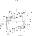
- FIG. 3 is a side view of the cutting insert 1 as viewed from the side of a peripheral side surface thereof.
- the cutting insert 1 is for an end mill which may suitably be used for high-feed machining. As shown in FIGS. 1 and 2 , the cutting insert 1 has a substantially rectangular parallelepiped.
- the cutting insert 1 includes first and second end surfaces 10 and 11 opposed to each other, a peripheral side surface 12 extending between the first and second end surfaces 10 and 11, and cutting edges 13 formed at a part of intersecting edges between the two end surfaces 10 and 11 and the peripheral side surface 12.
- a fixing hole 14 that penetrates in an end surface direction A (the top-down direction in FIG. 3 ) from the first end surface 10 to the second end surface 11 is provided in the center of the cutting insert 1.
- the first and second end surfaces 10 and 11 each have a substantially rectangular shape.
- the first end surface 10 includes a pair of short sides 20 and 21 opposed to each other, a pair of long sides 22 and 23 opposed to each other, and four corner parts 24, 25, 26, and 27.
- the first end surface 10 is provided with a chip breaker (groove) 28 along the cutting edge 13 (each of the short sides 20 and 21).
- the second end surface 11 has the same structure as that of the first end surface 10.
- the peripheral side surface 12 has four peripheral side surface parts 30, 31, 32, and 33 corresponding to the sides of the rectangular shapes of the end surfaces 10 and 11.
- the peripheral side surface parts 30 and 32 correspond to the short sides 20 and 21 and are curved substantially outward as viewed from the side of the end surface 10.
- the peripheral side surface parts 31 and 33 correspond to the long sides 22 and 23 and are formed linearly and parallel to each other as viewed from the side of the end surface 10.
- the cutting edges 13 are formed at intersecting edges (short sides 20) between the peripheral side surface part 30 and the end surfaces 10 and 11 and at intersecting edges (short sides 21) between the peripheral side surface part 32 and the end surfaces 10 and 11.
- the cutting edge 13 between the peripheral side surface part 30 and the end surface 10 has a first corner edge 50 formed at a first corner part 24, a second corner edge 51 formed at a second corner part 25, and a major cutting edge 52, an end cutting edge 53, and a minor cutting edge 54 that are provided between the first and second corner edges 50 and 51 and connected with one another. More specifically, the cutting edge 13 has the first corner edge 50, the major cutting edge 52, the end cutting edge 53, the minor cutting edge 54, and the second corner edge 51 continuously in this order from the first corner part 24 to the second corner part 25.
- the end cutting edge 53 is formed to have a circular-arc shape which projects outward as viewed from the side of the end surface 10.
- the arc radius R1 of the end cutting edge 53 is from 1/3 to 1/1 of the width W of the cutting insert 1.
- the width w1 of the end cutting edge 53 as viewed from the side of the end surface 10 is from 15% to 50%, preferably from 17% to 44% of the width W of the cutting insert 1 in a short side direction B (a direction connecting the outer end of the first corner edge 50 and the outer end of the second corner edge 51).
- the end cutting edge 53 is provided across a virtual center plane (center line) C in the longitudinal direction S through the center of the short side direction B of the cutting insert 1.
- the major cutting edge 52 connects the end cutting edge 53 and the first corner edge 50 (at a connecting point P3) and is for example linear as viewed from the side of the end surface 10.
- the minor cutting edge 54 connects the end cutting edge 53 and the second corner edge 51 (at a connecting point P4) and is for example linear as viewed from the side of the end surface 10.
- the first and second corner edges 50 and 51 are curved to conform to the shapes of the corner parts 24 and 25, respectively. Note that the major cutting edge 52, the minor cutting edge 54, the first corner edge 50, and the second corner edge 51 each have a width (length) set as appropriate according to the width w1 of the end cutting edge 53.
- the end cutting edge 53 on the side of the end surface 10 is provided across the virtual center plane (center line) C in the end surface direction A through the center of the cutting insert 1 in the short side direction B, and the first end (connecting point P1) on the side of the major cutting edge 52 is in a position higher than the second end (connecting point P2) on the side of the minor cutting edge 54 in the end surface direction A.
- the end cutting edge 53 on the side of the end surface 10 includes a first curve 53a which projects upward and a second curve 53b which projects downward and the curves are continuous with each other as viewed from the side of the peripheral side surface part 30.
- the major cutting edge 52 is curved upward and connected smoothly with the first curve 53a.
- the minor cutting edge 54 is curved downward and connected smoothly with the second curve 53b.
- the first corner edge 50 on the side of the end surface 10 is for example curved upward and smoothly connected with the major cutting edge 52.
- the highest point is in the vicinity of the connecting point P3 between the first corner edge 50 and the major cutting edge 52, and the outer end of the first corner edge 50 is slightly lowered.
- the second corner edge 51 is for example curved downward and smoothly connected with the minor cutting edge 54.
- the lowest point is in the vicinity of the connecting point P4 between the second corner edge 51 and the minor cutting edge 54, and the outer end of the second corner edge 51 is slightly raised.
- an angle ⁇ 1 formed between a straight line L1 which connects the opposed ends (connecting points P1 and P2) of the end cutting edge 53 and a line (plane) L2 orthogonal to the center line C of the cutting insert 1 is greater than 0° and smaller than 20°.
- the cutting edge 13 which corresponds to the edge between the peripheral side surface part 30 and the end surface 11 and the cutting edge 13 on the end surface 10 are arranged with 180°-rotational symmetry around a central axis D of the cutting insert 1 as viewed from the side of the peripheral side surface part 30 and have the same structure as that of the cutting edge 13 on the side of the end surface 10 above. More specifically, the cutting edge 13 between the peripheral side surface part 30 and the end surface 11 includes the first corner edge 50, the major cutting edge 52, the end cutting edge 53, the minor cutting edge 54, and the second corner edge 51 continuously in this order from the second corner part 25 to the first corner part 24.
- the cutting edge 13 which corresponds to the edge between the peripheral side surface part 32 and the end surface 10 and the cutting edge 13 which corresponds to the edge between the peripheral side surface part 32 and the end surface 11 are arranged with 180°-rotational symmetry around a central axis E (in FIG. 2 ) of the cutting insert 1 as the cutting edge 13 on the side of the peripheral side surface part 30 is viewed from the side of the end surface 10, and have the same structure as the cutting edge 13 on the side of the peripheral side surface part 30 as shown in FIG. 3 .
- the cutting insert 1 according to the embodiment is suitably used for high feed machining performed at high feeding speed.
- an angle ⁇ 3 formed between a line K1 connecting an outer end J1 of the first corner edge 50 and a point J2 corresponding to the outermost projecting part of the circular-arc shape of the end cutting edge 53 and a line K2 connecting an outer end J3 of the second corner edge 51 and the point J2 corresponding to the outermost projecting part of the circular-arc shape of the end cutting edge 53 is not more than 150°, preferably from 120° to 140°.
- the width W of the cutting insert 1 in the short side direction B is for example about 6 mm
- the length of the cutting insert 1 in the longitudinal direction S is about 12 mm.
- the cutting insert 1 has a thickness (the distance between the end surfaces 10 and 11) of about 3.5 mm.
- the material of the cutting insert 1 may be selected from, but not limited to, any of hard materials such as cemented carbide, cermet, ceramics, and a sintered body containing cubic boron nitride or any of the hard materials having a surface coated with a PVD or CVD coating film, or monocrystalline diamond or a sintered body containing diamond.
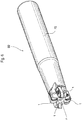
- the cutting tool 60 as shown in FIG. 6 is an indexable end mill.
- the cutting tool 60 includes a tool body part 70 and cutting inserts 1.
- the tool body part 70 is formed to have a columnar shape and has its central axis serving as a rotational axis F.
- a plurality of cutting inserts 1, e.g., four cutting inserts are mounted at equal intervals around the rotational axis F at the leading end of the tool body part 70. Note that the number of the cutting inserts 1 mounted to the tool body part 70 is not limited to four.
- the cutting inserts 1 are mounted so that the first end surfaces 10 or the second end surfaces 11 are directed in a rotation direction G and the peripheral side surface parts 30 or 32 are arranged to face the leading end side of the cutting tool 60.
- the cutting inserts 1 are mounted so that the line L1 connecting the opposed ends P1 and P2 of the end cutting edge 53 of the cutting insert 1 is at an angle ⁇ 2 from -10° to +6°, preferably from -10° to +2° in the rotation direction G with respect to a line L3 connecting the connecting point P1 between the end cutting edge 53 and the major cutting edge 52 of the cutting insert 1 and the rotational axis F of the cutting tool 60 (where a positive value corresponds to the rotation direction G and a negative value corresponds to the direction inverse to the rotation direction G).
- the cutting edge 13 has the circular-arc shaped end cutting edge 53 which projects outward as viewed from the side of the end surface 10 or 11, the end cutting edge 53 has a width w1 which is from 15% to 50% of the width W of the cutting insert 1, and the arc radius R1 of the end cutting edge 53 is from 1/3 to 1/1 of the width W of the cutting insert 1.
- the width w1 of the end cutting edge 53 is sufficiently large and the arc is gentle, so that the end cutting edge 53 can have increased strength, and fracture in the cutting edge 13 during cutting can be suppressed.
- the end cutting edge 53 is arranged across the center line C of the cutting insert 1, and the first end (connecting point P1) of the end cutting edge 53 on the side of the major cutting edge 52 is in a position higher than the second end (connecting point P2) of the end cutting edge 53 on the opposite side to the major cutting edge 52.
- the cutting edge 13 contacts a work in the order from the side of the end cutting edge 53 toward the major cutting edge 52 during cutting, so that fracture in the cutting edge 13 during cutting can be more appropriately suppressed.
- the end cutting edge 53 includes a first curve 53a which projects outward and a second curve 53b which projects inward, the curves are provided continuously with each other, and the first curve 53a is connected to the major cutting edge 52, while as viewed from the side of the peripheral side surface 12, the angle ⁇ 1 formed between the straight line L1 connecting the opposed ends (connecting points P1 and P2) of the end cutting edge 53 and the plane L2 orthogonal to the center line C of the cutting insert 1 is greater than 0° and smaller than 20°.
- the end cutting edge 53 is relatively gently raised toward the major cutting edge 52, so that abrupt application of a load upon the end cutting edge 53 during cutting can be avoided, and fracture in the cutting edge 13 can be more appropriately suppressed.
- the cutting edge 13 has the minor cutting edge 54 between the end cutting edge 53 and the second corner edge 51, and therefore the process of excavation with the cutting tool 60 in the rotation direction can appropriately be carried out.
- the cutting insert 1 is mounted so that, as viewed from the side of the leading end of the tool body part 70, the angle ⁇ 2 formed between the line L1 connecting the opposed ends (connecting points P1 and P2) of the end cutting edge 53 of the cutting insert 1 and the line L3 connecting the connecting point P2 between the end cutting edge 53 and the major cutting edge 52 of the cutting insert 1 and the rotational axis F of the cutting tool 60 is from -10° to +6° in the rotation direction G.
- the strength of the cutting edge 13 and the chip discharging capability can be well balanced.
- the end cutting edge 53 for example is not limited to that according to the embodiment.
- the end cutting edge 53 may include the first curve 53a which projects upward, the second curve 53b which projects downward, and a straight line 53c provided between the first and second curves 53a and 53b and connected continuously to the first and second curves 53a and 53b as viewed from the side of the peripheral side surface part 30.
- the end cutting edge 53 may include a plurality of straight lines 53d connected with one another as viewed from the side of the peripheral side surface part 30 and may be inclined downward from the major cutting edge 52 to the minor cutting edge 54.
- the cutting edge 13 does not have to include the minor cutting edge 54. More specifically, the cutting edge 13 may include the first corner edge 50, the major cutting edge 52, the end cutting edge 53, and the second corner edge 51 continuously connected in this order.
- the structure of the other part of the cutting insert 1 is not limited by the embodiment.
- the cutting insert 1 may have a diamond shape instead of the substantially rectangular shape.
- the cutting insert 1 may have any of a triangular shape, a pentagonal shape, a hexagonal shape, and an octagonal shape.
- the position or number of cutting edges 13 is not limited to those according to the embodiment.
- the cutting edges 13 are provided at the opposed end surfaces 10 and 11 of the cutting insert 1, while the cutting edges may be provided at only one of the end surfaces.
- the cutting edges 13 are provided at the two short sides of each of the end surfaces 10 and 11, while the cutting edges may be provided at one or three sides as a part of the end surface or at all the four sides of the end surface.
- the cutting tool 60 according to the embodiment is an indexable end mill, but the present invention may be applied to other kinds of cutting tools such as a milling cutter and a drill.
- the present invention is useful in providing a cutting insert capable of suppressing cutting edge fracture when a work having high hardness is machined.
Landscapes
- Engineering & Computer Science (AREA)
- Mechanical Engineering (AREA)
- Physics & Mathematics (AREA)
- Geometry (AREA)
- Milling Processes (AREA)
- Drilling Tools (AREA)
Abstract
Description
- The present invention relates to a cutting insert and a cutting tool.
- An indexable end mill has been used as a cutting tool for machining for a mold, etc. The cutting tool of this kind includes a substantially columnar tool body part and a cutting insert mounted at an axial leading end of the tool body part.
- In relation to the cutting tool as described above, it has been an important object to improve the strength of the edge in order to achieve high-feed machining. The cutting insert proposed in
WO 2010/114094 has a major cutting edge formed to have a greater thickness than a central flat surface thereof, so that the major cutting edge of the cutting insert has increased rigidity. - However, the above-described cutting tool does not have an edge strong enough to machine hard works with a hardness exceeding 50HRC which have become more available in recent years, and the edge may fracture during machining, which reduces the useful life or efficiency of the cutting insert.
- With the foregoing in view, it is an object of the present invention to provide a cutting insert and a cutting tool capable of suppressing edge fracture when hard works are machined.
- A cutting insert according to one embodiment of the present invention includes two end surfaces having a plurality of corner parts and opposed to each other, a peripheral side surface extending between the two end surfaces, and a cutting edge formed at an intersecting edge between at least one of the two end surfaces and the peripheral side surface, the cutting edge has at least a first corner edge formed at a first corner part, a second corner edge formed at a second corner part adjacent to the first corner part, and a major cutting edge and an end cutting edge provided between the first and second corner edges and connected to each other, the end cutting edge has a circular-arc shape, which projects outward, as viewed from an end surface side, the end cutting edge has a width which is from 15% to 50% of a width of the cutting insert in a direction connecting an outer end of the first corner edge and an outer end of the second corner edge, and the end cutting edge has an arc radius which is from 1/3 to 1/1 of the width of the cutting insert.
- According to the embodiment, the width and the arc radius of the end cutting edge are defined as described above, so that the end cutting edge can have increased strength and the edge is less likely to fracture during cutting.
- The end cutting edge may be provided across a center line passing through a center in a width-wise direction of the cutting insert and extending in a direction orthogonal to the widthwise direction as viewed from a side of a peripheral side surface, and a first end of the end cutting edge on a side of the major cutting edge may be in a position higher than a second end of the end cutting edge on the opposite side to the major cutting edge.
- The end cutting edge may include a first curve, which projects upward, and a second curve, which projects downward, as viewed from the side of the peripheral side surface, the first curve may be connected to the major cutting edge, and an angle formed between a straight line connecting opposed ends of the end cutting edge and a line orthogonal to the center line of the cutting insert may be greater than 0° and smaller than 20°.
- The end cutting edge may have the first curve, the second curve, and a straight line provided between the first and second curves and continuously connected to the first and second curves.
- The cutting edge may have a minor cutting edge between the end cutting edge and the second corner edge.
- An angle formed between a line connecting the outer end of the first corner edge and an outer most point of the circular-arc shape of the end cutting edge and a line connecting the outer end of the second corner edge and the outer most point of the circular-arc shape of the end cutting edge may be at most 150°.
- A cutting tool according to another embodiment of the present invention includes a tool body part and the above-described cutting insert mounted at a leading end of the tool body part, and the cutting insert is mounted around a rotational axis of the tool body part and has an end surface thereof directed in a rotation direction.
- As viewed from a leading end side of the tool body part, the cutting insert may be mounted so that a line connecting opposed ends of the end cutting edge of the cutting insert is arranged at an angle from -10° to 6° in the rotation direction with respect to a line connecting a connecting point between the end cutting edge and the major cutting edge of the cutting insert, and the rotational axis of the cutting tool.
- The angle may be in the range from -10° to 2°.
-
-
FIG. 1 is a perspective view of a cutting insert; -
FIG. 2 is a front view of the cutting insert as viewed from the side of an end surface thereof; -
FIG. 3 is a side view of the cutting insert as viewed from the side of a peripheral side surface thereof; -
FIG. 4 is an enlarged view of a first end surface of the cutting insert; -
FIG. 5 is an enlarged view of the first end surface of the cutting insert indicating an angle α3; -
FIG. 6 is a perspective view of a cutting tool; -
FIG. 7 is a view of the cutting tool as viewed from the side of a leading end thereof; -
FIG. 8 is a schematic view of an end cutting edge having another shape; and -
FIG. 9 is a schematic view of the end cutting edge having another shape. - Now, a preferred embodiment of the present invention will be described with reference to the accompanying drawings. Note that the same elements are designated by the same reference characters, and their description will not be repeated. The positional relation for example about the top, bottom, left, and right is based on the positional relation shown in the drawings unless otherwise specified. The dimensional ratios for drawings are not limited to those shown in the drawings. The following embodiment is an example for describing the present invention and is not intended to limit the present invention.
-
FIG. 1 is a perspective view of acutting insert 1 according to the embodiment, andFIG. 2 is a front view of thecutting insert 1 as viewed from the side of an end surface thereof.FIG. 3 is a side view of thecutting insert 1 as viewed from the side of a peripheral side surface thereof. - The
cutting insert 1 is for an end mill which may suitably be used for high-feed machining. As shown inFIGS. 1 and2 , thecutting insert 1 has a substantially rectangular parallelepiped. Thecutting insert 1 includes first andsecond end surfaces peripheral side surface 12 extending between the first andsecond end surfaces edges 13 formed at a part of intersecting edges between the twoend surfaces peripheral side surface 12. Afixing hole 14 that penetrates in an end surface direction A (the top-down direction inFIG. 3 ) from thefirst end surface 10 to thesecond end surface 11 is provided in the center of thecutting insert 1. - As viewed from the side of the
end surfaces second end surfaces FIG. 2 , thefirst end surface 10 includes a pair ofshort sides long sides corner parts first end surface 10 is provided with a chip breaker (groove) 28 along the cutting edge 13 (each of theshort sides 20 and 21). Thesecond end surface 11 has the same structure as that of thefirst end surface 10. - The
peripheral side surface 12 has four peripheralside surface parts end surfaces side surface parts short sides end surface 10. The peripheralside surface parts long sides end surface 10. - As shown in
FIGS. 1 to 3 , thecutting edges 13 are formed at intersecting edges (short sides 20) between the peripheralside surface part 30 and theend surfaces side surface part 32 and theend surfaces - As shown in
FIG. 2 , for example thecutting edge 13 between the peripheralside surface part 30 and theend surface 10 has afirst corner edge 50 formed at afirst corner part 24, asecond corner edge 51 formed at asecond corner part 25, and a majorcutting edge 52, an endcutting edge 53, and aminor cutting edge 54 that are provided between the first andsecond corner edges cutting edge 13 has thefirst corner edge 50, the majorcutting edge 52, theend cutting edge 53, theminor cutting edge 54, and thesecond corner edge 51 continuously in this order from thefirst corner part 24 to thesecond corner part 25. - As shown in
FIG. 4 , theend cutting edge 53 is formed to have a circular-arc shape which projects outward as viewed from the side of theend surface 10. The arc radius R1 of theend cutting edge 53 is from 1/3 to 1/1 of the width W of thecutting insert 1. The width w1 of theend cutting edge 53 as viewed from the side of the end surface 10 (the distance from a connecting point P1 between theend cutting edge 53 and themajor cutting edge 52 to a connecting point P2 between theend cutting edge 53 and the minor cutting edge 54) is from 15% to 50%, preferably from 17% to 44% of the width W of the cutting insert 1 in a short side direction B (a direction connecting the outer end of thefirst corner edge 50 and the outer end of the second corner edge 51). - The
end cutting edge 53 is provided across a virtual center plane (center line) C in the longitudinal direction S through the center of the short side direction B of thecutting insert 1. Themajor cutting edge 52 connects theend cutting edge 53 and the first corner edge 50 (at a connecting point P3) and is for example linear as viewed from the side of theend surface 10. Theminor cutting edge 54 connects theend cutting edge 53 and the second corner edge 51 (at a connecting point P4) and is for example linear as viewed from the side of theend surface 10. The first andsecond corner edges corner parts major cutting edge 52, theminor cutting edge 54, thefirst corner edge 50, and thesecond corner edge 51 each have a width (length) set as appropriate according to the width w1 of theend cutting edge 53. - As shown in
FIG. 3 , as viewed from the side of the peripheralside surface part 30, theend cutting edge 53 on the side of theend surface 10 is provided across the virtual center plane (center line) C in the end surface direction A through the center of the cutting insert 1 in the short side direction B, and the first end (connecting point P1) on the side of themajor cutting edge 52 is in a position higher than the second end (connecting point P2) on the side of theminor cutting edge 54 in the end surface direction A. - The
end cutting edge 53 on the side of theend surface 10 includes afirst curve 53a which projects upward and asecond curve 53b which projects downward and the curves are continuous with each other as viewed from the side of the peripheralside surface part 30. Themajor cutting edge 52 is curved upward and connected smoothly with thefirst curve 53a. Theminor cutting edge 54 is curved downward and connected smoothly with thesecond curve 53b. - As viewed from the side of the peripheral
side surface part 30, thefirst corner edge 50 on the side of theend surface 10 is for example curved upward and smoothly connected with themajor cutting edge 52. The highest point is in the vicinity of the connecting point P3 between thefirst corner edge 50 and themajor cutting edge 52, and the outer end of thefirst corner edge 50 is slightly lowered. Thesecond corner edge 51 is for example curved downward and smoothly connected with theminor cutting edge 54. The lowest point is in the vicinity of the connecting point P4 between thesecond corner edge 51 and theminor cutting edge 54, and the outer end of thesecond corner edge 51 is slightly raised. - As viewed from the side of the peripheral
side surface part 30, an angle α1 formed between a straight line L1 which connects the opposed ends (connecting points P1 and P2) of theend cutting edge 53 and a line (plane) L2 orthogonal to the center line C of the cuttinginsert 1 is greater than 0° and smaller than 20°. - As shown in
FIG. 3 , thecutting edge 13 which corresponds to the edge between the peripheralside surface part 30 and theend surface 11 and thecutting edge 13 on theend surface 10 are arranged with 180°-rotational symmetry around a central axis D of the cuttinginsert 1 as viewed from the side of the peripheralside surface part 30 and have the same structure as that of thecutting edge 13 on the side of theend surface 10 above. More specifically, thecutting edge 13 between the peripheralside surface part 30 and theend surface 11 includes thefirst corner edge 50, themajor cutting edge 52, theend cutting edge 53, theminor cutting edge 54, and thesecond corner edge 51 continuously in this order from thesecond corner part 25 to thefirst corner part 24. - The
cutting edge 13 which corresponds to the edge between the peripheralside surface part 32 and theend surface 10 and thecutting edge 13 which corresponds to the edge between the peripheralside surface part 32 and theend surface 11 are arranged with 180°-rotational symmetry around a central axis E (inFIG. 2 ) of the cuttinginsert 1 as thecutting edge 13 on the side of the peripheralside surface part 30 is viewed from the side of theend surface 10, and have the same structure as thecutting edge 13 on the side of the peripheralside surface part 30 as shown inFIG. 3 . - The cutting
insert 1 according to the embodiment is suitably used for high feed machining performed at high feeding speed. For example, as shown inFIG. 5 , when the cuttinginsert 1 is viewed from the side of theend surface 10, an angle α3 formed between a line K1 connecting an outer end J1 of thefirst corner edge 50 and a point J2 corresponding to the outermost projecting part of the circular-arc shape of theend cutting edge 53 and a line K2 connecting an outer end J3 of thesecond corner edge 51 and the point J2 corresponding to the outermost projecting part of the circular-arc shape of theend cutting edge 53 is not more than 150°, preferably from 120° to 140°. - As for the size of the cutting
insert 1, the width W of the cuttinginsert 1 in the short side direction B is for example about 6 mm, the length of the cuttinginsert 1 in the longitudinal direction S is about 12 mm. The cuttinginsert 1 has a thickness (the distance between the end surfaces 10 and 11) of about 3.5 mm. - The material of the cutting
insert 1 may be selected from, but not limited to, any of hard materials such as cemented carbide, cermet, ceramics, and a sintered body containing cubic boron nitride or any of the hard materials having a surface coated with a PVD or CVD coating film, or monocrystalline diamond or a sintered body containing diamond. - Now, a
cutting tool 60 to which thecutting insert 1 is mounted will be described. The cuttingtool 60 as shown inFIG. 6 is an indexable end mill. The cuttingtool 60 includes atool body part 70 and cutting inserts 1. Thetool body part 70 is formed to have a columnar shape and has its central axis serving as a rotational axis F. A plurality of cuttinginserts 1, e.g., four cutting inserts are mounted at equal intervals around the rotational axis F at the leading end of thetool body part 70. Note that the number of the cutting inserts 1 mounted to thetool body part 70 is not limited to four. As shown inFIG. 7 , the cutting inserts 1 are mounted so that the first end surfaces 10 or the second end surfaces 11 are directed in a rotation direction G and the peripheralside surface parts cutting tool 60. - In this manner, as viewed from the side of the leading end of the
tool body part 70, the cutting inserts 1 are mounted so that the line L1 connecting the opposed ends P1 and P2 of theend cutting edge 53 of the cuttinginsert 1 is at an angle α2 from -10° to +6°, preferably from -10° to +2° in the rotation direction G with respect to a line L3 connecting the connecting point P1 between theend cutting edge 53 and themajor cutting edge 52 of the cuttinginsert 1 and the rotational axis F of the cutting tool 60 (where a positive value corresponds to the rotation direction G and a negative value corresponds to the direction inverse to the rotation direction G). - According to the embodiment, the
cutting edge 13 has the circular-arc shapedend cutting edge 53 which projects outward as viewed from the side of theend surface end cutting edge 53 has a width w1 which is from 15% to 50% of the width W of the cuttinginsert 1, and the arc radius R1 of theend cutting edge 53 is from 1/3 to 1/1 of the width W of the cuttinginsert 1. In this way, the width w1 of theend cutting edge 53 is sufficiently large and the arc is gentle, so that theend cutting edge 53 can have increased strength, and fracture in thecutting edge 13 during cutting can be suppressed. - As viewed from the side of the
peripheral side surface 12, theend cutting edge 53 is arranged across the center line C of the cuttinginsert 1, and the first end (connecting point P1) of theend cutting edge 53 on the side of themajor cutting edge 52 is in a position higher than the second end (connecting point P2) of theend cutting edge 53 on the opposite side to themajor cutting edge 52. As a result, thecutting edge 13 contacts a work in the order from the side of theend cutting edge 53 toward themajor cutting edge 52 during cutting, so that fracture in thecutting edge 13 during cutting can be more appropriately suppressed. - As viewed from the side of the
peripheral side surface 12, theend cutting edge 53 includes afirst curve 53a which projects outward and asecond curve 53b which projects inward, the curves are provided continuously with each other, and thefirst curve 53a is connected to themajor cutting edge 52, while as viewed from the side of theperipheral side surface 12, the angle α1 formed between the straight line L1 connecting the opposed ends (connecting points P1 and P2) of theend cutting edge 53 and the plane L2 orthogonal to the center line C of the cuttinginsert 1 is greater than 0° and smaller than 20°. As a result, theend cutting edge 53 is relatively gently raised toward themajor cutting edge 52, so that abrupt application of a load upon theend cutting edge 53 during cutting can be avoided, and fracture in thecutting edge 13 can be more appropriately suppressed. - The
cutting edge 13 has theminor cutting edge 54 between theend cutting edge 53 and thesecond corner edge 51, and therefore the process of excavation with the cuttingtool 60 in the rotation direction can appropriately be carried out. - In the
cutting tool 60, the cuttinginsert 1 is mounted so that, as viewed from the side of the leading end of thetool body part 70, the angle α2 formed between the line L1 connecting the opposed ends (connecting points P1 and P2) of theend cutting edge 53 of the cuttinginsert 1 and the line L3 connecting the connecting point P2 between theend cutting edge 53 and themajor cutting edge 52 of the cuttinginsert 1 and the rotational axis F of thecutting tool 60 is from -10° to +6° in the rotation direction G. As a result, the strength of thecutting edge 13 and the chip discharging capability can be well balanced. - Although the preferred embodiment of the present invention has been described with reference to the accompanying drawings, the same is not intended to limit the present invention. It is understood that variations and modifications would be apparent to those skilled in the art within the scope of the concept recited in the claims, and the variations and modifications naturally fall within the technical scope of the present invention.
- The structure of the
end cutting edge 53 for example is not limited to that according to the embodiment. As shown inFIG. 8 , theend cutting edge 53 may include thefirst curve 53a which projects upward, thesecond curve 53b which projects downward, and astraight line 53c provided between the first andsecond curves second curves side surface part 30. - For example as shown in
FIG. 9 , theend cutting edge 53 may include a plurality ofstraight lines 53d connected with one another as viewed from the side of the peripheralside surface part 30 and may be inclined downward from themajor cutting edge 52 to theminor cutting edge 54. - According to the embodiment described above, the
cutting edge 13 does not have to include theminor cutting edge 54. More specifically, thecutting edge 13 may include thefirst corner edge 50, themajor cutting edge 52, theend cutting edge 53, and thesecond corner edge 51 continuously connected in this order. The structure of the other part of the cuttinginsert 1 is not limited by the embodiment. For example, the cuttinginsert 1 may have a diamond shape instead of the substantially rectangular shape. The cuttinginsert 1 may have any of a triangular shape, a pentagonal shape, a hexagonal shape, and an octagonal shape. The position or number ofcutting edges 13 is not limited to those according to the embodiment. The cutting edges 13 are provided at the opposed end surfaces 10 and 11 of the cuttinginsert 1, while the cutting edges may be provided at only one of the end surfaces. The cutting edges 13 are provided at the two short sides of each of the end surfaces 10 and 11, while the cutting edges may be provided at one or three sides as a part of the end surface or at all the four sides of the end surface. - The cutting
tool 60 according to the embodiment is an indexable end mill, but the present invention may be applied to other kinds of cutting tools such as a milling cutter and a drill. - An experiment was conducted in which the time until fracture of a cutting edge was measured using each of cutting inserts having structures listed in Table 1. The experiment was conducted under the conditions in which the cutting speed Vc was 120 m/min, the advancing amount of one edge per rotation fz (so-called "feed per edge") was 0.32 mm, the cutting edge width ae was 50.5 mm, the tool diameter was 80 mm, the kind of work was SKD61 (having a hardness of 52HRC), and the number of cutting inserts mounted with a tool was one. The experiment result is given in Table 1.
[Table 1] Ratio of end cutting edge width to cutting insert edge width (%) Arc radius of end cutting edge Machining time until fracture (min) Inventive example 1 17 1/3 42 Inventive example 2 30 3.5/6 43 Inventive example 3 40 11/12 40 Comparative example 1 14 1/3 30 Comparative example 2 67 8/6.35 25 Comparative example 3 87 15/14 30 - The present invention is useful in providing a cutting insert capable of suppressing cutting edge fracture when a work having high hardness is machined.
Claims (9)
- A cutting insert, comprising:two end surfaces having a plurality of corner parts and opposed to each other;a peripheral side surface extending between the two end surfaces; anda cutting edge formed at an intersecting edge between at least one of the two end surfaces and the peripheral side surface,the cutting edge having at least a first corner edge formed at a first corner part, a second corner edge formed at a second corner part adjacent to the first corner part, and a major cutting edge and an end cutting edge provided between the first and second corner edges and connected to each other,the end cutting edge having a circular-arc shape, which projects outward, as viewed from an end surface side, the end cutting edge having a width which is from 15% to 50% of a width of the cutting insert in a direction connecting an outer end of the first corner edge and an outer end of the second corner edge, the end cutting edge having an arc radius which is from 1/3 to 1/1 of the width of the cutting insert.
- The cutting insert according to claim 1, wherein the end cutting edge is provided across a center line passing through a center in a width-wise direction of the cutting insert and extending in a direction orthogonal to the widthwise direction as viewed from a side of a peripheral side surface, and a first end of the end cutting edge on a side of the major cutting edge is in a position higher than a second end of the end cutting edge on the opposite side to the major cutting edge.
- The cutting insert according to claim 2, wherein the end cutting edge includes a first curve, which projects upward, and a second curve, which projects downward, as viewed from the side of the peripheral side surface, the first curve is connected to the major cutting edge, and an angle formed between a straight line connecting opposed ends of the end cutting edge and a line orthogonal to the center line of the cutting insert is greater than 0° and smaller than 20°.
- The cutting insert according to claim 3, wherein the end cutting edge has the first curve, the second curve, and a straight line provided between the first and second curves and continuously connected to the first and second curves.
- The cutting insert according to any one of claims 1 to 4, wherein the cutting edge has a minor cutting edge between the end cutting edge and the second corner edge.
- The cutting insert according to any one of claims 1 to 5, wherein an angle formed between a line connecting the outer end of the first corner edge and an outer most point of the circular-arc shape of the end cutting edge and a line connecting the outer end of the second corner edge and the outer most point of the circular-arc shape of the end cutting edge is at most 150°.
- A cutting tool, comprising:a tool body part; andthe cutting insert of any one of claims 1 to 6 mounted at a leading end of the tool body part, whereinthe cutting insert is mounted around a rotational axis of the tool body part and has an end surface thereof directed in a rotation direction.
- The cutting tool according to claim 7, wherein as viewed from a leading end side of the tool body part, the cutting insert is mounted so that a line connecting opposed ends of the end cutting edge of the cutting insert is arranged at an angle from -10° to 6° in the rotation direction with respect to a line connecting a connecting point between the end cutting edge and the major cutting edge of the cutting insert, and the rotational direction of the cutting tool.
- The cutting tool according to claim 8, wherein the range of the angle is from -10° to 2°.
Applications Claiming Priority (1)
| Application Number | Priority Date | Filing Date | Title |
|---|---|---|---|
| JP2017155483A JP6562983B2 (en) | 2017-08-10 | 2017-08-10 | Cutting insert and cutting tool |
Publications (2)
| Publication Number | Publication Date |
|---|---|
| EP3441170A1 true EP3441170A1 (en) | 2019-02-13 |
| EP3441170B1 EP3441170B1 (en) | 2025-11-05 |
Family
ID=63012859
Family Applications (1)
| Application Number | Title | Priority Date | Filing Date |
|---|---|---|---|
| EP18184370.7A Active EP3441170B1 (en) | 2017-08-10 | 2018-07-19 | Cutting insert and cutting tool |
Country Status (4)
| Country | Link |
|---|---|
| US (1) | US10583502B2 (en) |
| EP (1) | EP3441170B1 (en) |
| JP (1) | JP6562983B2 (en) |
| CN (1) | CN109382530B (en) |
Cited By (1)
| Publication number | Priority date | Publication date | Assignee | Title |
|---|---|---|---|---|
| EP3998128A4 (en) * | 2019-09-10 | 2022-09-07 | YG-1 Co., Ltd. | CUTTING INSERT |
Families Citing this family (12)
| Publication number | Priority date | Publication date | Assignee | Title |
|---|---|---|---|---|
| US10315258B2 (en) * | 2014-02-26 | 2019-06-11 | Tungaloy Corporation | Cutting insert and cutting tool |
| JP6338204B1 (en) * | 2017-08-29 | 2018-06-06 | 株式会社タンガロイ | Cutting insert and cutting tool |
| KR102015290B1 (en) * | 2017-11-14 | 2019-08-28 | 한국야금 주식회사 | Cutting insert and cutting tool for mounting the same |
| JP6703317B1 (en) * | 2019-05-31 | 2020-06-03 | 株式会社タンガロイ | Cutting insert |
| JP6921385B2 (en) * | 2019-08-28 | 2021-08-18 | 株式会社タンガロイ | Cutting insert |
| CN110605426A (en) * | 2019-09-23 | 2019-12-24 | 浙江甬岭数控刀具有限公司 | A high precision U drill |
| JP7488332B2 (en) * | 2020-03-25 | 2024-05-21 | 京セラ株式会社 | Method for manufacturing rotary tools and machined products |
| JP6855024B1 (en) * | 2020-10-02 | 2021-04-07 | 株式会社タンガロイ | Cutting inserts and cutting tools equipped with them |
| CN113649631B (en) * | 2021-08-31 | 2022-06-03 | 株洲华锐精密工具股份有限公司 | Efficient cutting blade |
| JP1716009S (en) * | 2021-09-22 | 2022-05-27 | Cutting tools | |
| CN117226158B (en) * | 2023-11-13 | 2024-03-05 | 赣州澳克泰工具技术有限公司 | Cutting blade and cutting tool thereof |
| CN118808693B (en) * | 2024-09-19 | 2025-01-14 | 赣州澳克泰工具技术有限公司 | Cutting insert and cutting tool |
Citations (4)
| Publication number | Priority date | Publication date | Assignee | Title |
|---|---|---|---|---|
| JP2003275920A (en) * | 2002-03-20 | 2003-09-30 | Mitsubishi Materials Corp | Indexable inserts and indexable cutting tools |
| WO2010114094A1 (en) | 2009-04-02 | 2010-10-07 | 株式会社タンガロイ | Cutting insert and indexable cutting tool |
| EP3117941A1 (en) * | 2014-11-27 | 2017-01-18 | Tungaloy Corporation | Cutting insert, tool body, and cutting tool |
| WO2017051471A1 (en) * | 2015-09-25 | 2017-03-30 | 三菱日立ツール株式会社 | Cutting insert and replaceable tool edge rotary cutting tool |
Family Cites Families (22)
| Publication number | Priority date | Publication date | Assignee | Title |
|---|---|---|---|---|
| JP3010760B2 (en) * | 1991-03-08 | 2000-02-21 | 三菱マテリアル株式会社 | Indexable inserts and indexable cutters |
| JP3317490B2 (en) * | 1998-06-18 | 2002-08-26 | 日立ツール株式会社 | High feed indexable rotary tool |
| JP2000176726A (en) * | 1998-12-14 | 2000-06-27 | Mitsubishi Materials Corp | Indexable ball end mill with excellent wear resistance in high-speed cutting |
| EP1252955A1 (en) * | 2001-04-26 | 2002-10-30 | Mitsubishi Materials Corporation | Indexable insert |
| JP4304935B2 (en) * | 2002-03-11 | 2009-07-29 | 三菱マテリアル株式会社 | Cutting tools and throwaway inserts |
| JP3952853B2 (en) * | 2002-05-24 | 2007-08-01 | 三菱マテリアル株式会社 | Throwaway tip |
| JP4119967B2 (en) * | 2002-12-16 | 2008-07-16 | 日立ツール株式会社 | Blade-replaceable rotary tool |
| US7771142B2 (en) * | 2003-05-09 | 2010-08-10 | Kennametal Inc. | Cutting insert with elliptical cutting edge |
| US7220083B2 (en) * | 2003-10-15 | 2007-05-22 | Tdy Industries, Inc. | Cutting insert for high feed face milling |
| US7070363B2 (en) * | 2004-07-15 | 2006-07-04 | Kennametal Inc. | Cutting insert for high-speed milling cutter |
| SE527617C8 (en) * | 2004-09-06 | 2006-06-13 | Sandvik Intellectual Property | Milling tools, cutters for milling tools and solid milling tools |
| SE529108C2 (en) * | 2005-09-28 | 2007-05-02 | Seco Tools Ab | Milling and turning inserts for chip separating machining with cutting edges located lower a support surface |
| JP5568548B2 (en) * | 2008-04-14 | 2014-08-06 | テグテック・リミテッド | Replaceable cutting insert |
| IL203283A (en) * | 2010-01-13 | 2014-02-27 | Iscar Ltd | Cutting insert |
| WO2012002267A1 (en) * | 2010-06-30 | 2012-01-05 | 京セラ株式会社 | Insert and cutting tool, as well as method of manufacturing workpiece which is cut using said insert and cutting tool |
| IL208253A (en) * | 2010-09-19 | 2015-01-29 | Iscar Ltd | Milling cutter and cutting insert therefor |
| EP2805786B1 (en) * | 2013-05-21 | 2019-07-10 | Pramet Tools, S.R.O. | Indexable cutting insert having side supporting valley, and a milling tool |
| US10315258B2 (en) * | 2014-02-26 | 2019-06-11 | Tungaloy Corporation | Cutting insert and cutting tool |
| JP6337573B2 (en) * | 2014-03-31 | 2018-06-06 | 三菱日立ツール株式会社 | Cutting insert and cutting edge exchangeable rotary cutting tool |
| CN107405702B (en) * | 2015-05-19 | 2019-09-27 | 株式会社泰珂洛 | Tool bodies and cutting tools |
| EP3199284B1 (en) * | 2016-01-27 | 2018-12-12 | Pramet Tools, S.R.O. | An indexable cutting insert for an end mill tool and an end mill tool provided with such an insert |
| JP6338204B1 (en) * | 2017-08-29 | 2018-06-06 | 株式会社タンガロイ | Cutting insert and cutting tool |
-
2017
- 2017-08-10 JP JP2017155483A patent/JP6562983B2/en active Active
-
2018
- 2018-07-19 EP EP18184370.7A patent/EP3441170B1/en active Active
- 2018-07-28 US US16/048,257 patent/US10583502B2/en active Active
- 2018-08-03 CN CN201810875822.2A patent/CN109382530B/en active Active
Patent Citations (4)
| Publication number | Priority date | Publication date | Assignee | Title |
|---|---|---|---|---|
| JP2003275920A (en) * | 2002-03-20 | 2003-09-30 | Mitsubishi Materials Corp | Indexable inserts and indexable cutting tools |
| WO2010114094A1 (en) | 2009-04-02 | 2010-10-07 | 株式会社タンガロイ | Cutting insert and indexable cutting tool |
| EP3117941A1 (en) * | 2014-11-27 | 2017-01-18 | Tungaloy Corporation | Cutting insert, tool body, and cutting tool |
| WO2017051471A1 (en) * | 2015-09-25 | 2017-03-30 | 三菱日立ツール株式会社 | Cutting insert and replaceable tool edge rotary cutting tool |
Cited By (1)
| Publication number | Priority date | Publication date | Assignee | Title |
|---|---|---|---|---|
| EP3998128A4 (en) * | 2019-09-10 | 2022-09-07 | YG-1 Co., Ltd. | CUTTING INSERT |
Also Published As
| Publication number | Publication date |
|---|---|
| JP6562983B2 (en) | 2019-08-21 |
| US10583502B2 (en) | 2020-03-10 |
| US20190047059A1 (en) | 2019-02-14 |
| CN109382530B (en) | 2020-12-15 |
| CN109382530A (en) | 2019-02-26 |
| EP3441170B1 (en) | 2025-11-05 |
| JP2019034353A (en) | 2019-03-07 |
Similar Documents
| Publication | Publication Date | Title |
|---|---|---|
| EP3441170B1 (en) | Cutting insert and cutting tool | |
| EP1677934B1 (en) | Tangential cutting insert and milling cutter | |
| KR102424211B1 (en) | Cutting inserts and indexable cutting tools | |
| US10525540B2 (en) | Cutting insert and cutting tool | |
| EP3299102B1 (en) | Tool body in combination with a first cutting insert and a second cutting insert | |
| JP5751401B1 (en) | Replaceable cutting edge rotary cutting tool | |
| CN106232272B (en) | Cutting tip and cutting element | |
| WO2007037733A1 (en) | A milling insert and a milling tool | |
| EP3338931B1 (en) | Cutting insert and cutting tool | |
| CN109641293B (en) | Cutting insert and indexable insert type rotary cutting tool | |
| CN104785835A (en) | Cutting insert with finishing and roughing cutting edges | |
| CN109475944B (en) | Turning insert | |
| CN109862983B (en) | Cutting insert and indexable insert type rotary cutting tool | |
| JP5196077B2 (en) | Cutting inserts and cutting edge changeable turning tools | |
| US20210001408A1 (en) | Double-sided, polygonal cutting inserts with alternating concave and convex cutting edged | |
| JP2017024173A (en) | Cutting insert and edge replacing type rotary cutting tool | |
| CN109414771B (en) | Cutting insert and indexable insert type rotary cutting tool | |
| JP2015193049A (en) | Cutting insert, and tip replaceable rotary cutting tool | |
| EP3505284B1 (en) | Cutting insert, and indexable rotational cutting tool | |
| EP2890513A1 (en) | Milling tool holder and oval-shaped double-sided indexable cutting insert | |
| JP2004195563A (en) | Edge replaceable rotary tool and insert therefor | |
| JP2021088008A (en) | High hardness cutting tool | |
| CN214238909U (en) | Ball end milling cutter | |
| US12533737B2 (en) | Method for manufacturing a rotatable tool body to minimize cutting insert runout, a tool body produced therefrom, and a method of using such a tool body | |
| JP2004223627A (en) | Insert and knife edge replacement type rotating tool |
Legal Events
| Date | Code | Title | Description |
|---|---|---|---|
| PUAI | Public reference made under article 153(3) epc to a published international application that has entered the european phase |
Free format text: ORIGINAL CODE: 0009012 |
|
| STAA | Information on the status of an ep patent application or granted ep patent |
Free format text: STATUS: REQUEST FOR EXAMINATION WAS MADE |
|
| 17P | Request for examination filed |
Effective date: 20180818 |
|
| AK | Designated contracting states |
Kind code of ref document: A1 Designated state(s): AL AT BE BG CH CY CZ DE DK EE ES FI FR GB GR HR HU IE IS IT LI LT LU LV MC MK MT NL NO PL PT RO RS SE SI SK SM TR |
|
| AX | Request for extension of the european patent |
Extension state: BA ME |
|
| STAA | Information on the status of an ep patent application or granted ep patent |
Free format text: STATUS: EXAMINATION IS IN PROGRESS |
|
| 17Q | First examination report despatched |
Effective date: 20220414 |
|
| GRAP | Despatch of communication of intention to grant a patent |
Free format text: ORIGINAL CODE: EPIDOSNIGR1 |
|
| STAA | Information on the status of an ep patent application or granted ep patent |
Free format text: STATUS: GRANT OF PATENT IS INTENDED |
|
| INTG | Intention to grant announced |
Effective date: 20250602 |
|
| GRAS | Grant fee paid |
Free format text: ORIGINAL CODE: EPIDOSNIGR3 |
|
| GRAA | (expected) grant |
Free format text: ORIGINAL CODE: 0009210 |
|
| STAA | Information on the status of an ep patent application or granted ep patent |
Free format text: STATUS: THE PATENT HAS BEEN GRANTED |
|
| AK | Designated contracting states |
Kind code of ref document: B1 Designated state(s): AL AT BE BG CH CY CZ DE DK EE ES FI FR GB GR HR HU IE IS IT LI LT LU LV MC MK MT NL NO PL PT RO RS SE SI SK SM TR |
|
| REG | Reference to a national code |
Ref country code: CH Ref legal event code: F10 Free format text: ST27 STATUS EVENT CODE: U-0-0-F10-F00 (AS PROVIDED BY THE NATIONAL OFFICE) Effective date: 20251105 Ref country code: GB Ref legal event code: FG4D |
|
| REG | Reference to a national code |
Ref country code: DE Ref legal event code: R096 Ref document number: 602018086882 Country of ref document: DE |
|
| REG | Reference to a national code |
Ref country code: IE Ref legal event code: FG4D |
|
| REG | Reference to a national code |
Ref country code: NL Ref legal event code: MP Effective date: 20251105 |
|
| PG25 | Lapsed in a contracting state [announced via postgrant information from national office to epo] |
Ref country code: ES Free format text: LAPSE BECAUSE OF FAILURE TO SUBMIT A TRANSLATION OF THE DESCRIPTION OR TO PAY THE FEE WITHIN THE PRESCRIBED TIME-LIMIT Effective date: 20251105 |
|
| REG | Reference to a national code |
Ref country code: LT Ref legal event code: MG9D |
|
| PG25 | Lapsed in a contracting state [announced via postgrant information from national office to epo] |
Ref country code: NO Free format text: LAPSE BECAUSE OF FAILURE TO SUBMIT A TRANSLATION OF THE DESCRIPTION OR TO PAY THE FEE WITHIN THE PRESCRIBED TIME-LIMIT Effective date: 20260205 |
|
| PG25 | Lapsed in a contracting state [announced via postgrant information from national office to epo] |
Ref country code: FI Free format text: LAPSE BECAUSE OF FAILURE TO SUBMIT A TRANSLATION OF THE DESCRIPTION OR TO PAY THE FEE WITHIN THE PRESCRIBED TIME-LIMIT Effective date: 20251105 Ref country code: HR Free format text: LAPSE BECAUSE OF FAILURE TO SUBMIT A TRANSLATION OF THE DESCRIPTION OR TO PAY THE FEE WITHIN THE PRESCRIBED TIME-LIMIT Effective date: 20251105 Ref country code: AT Free format text: LAPSE BECAUSE OF FAILURE TO SUBMIT A TRANSLATION OF THE DESCRIPTION OR TO PAY THE FEE WITHIN THE PRESCRIBED TIME-LIMIT Effective date: 20251105 |
|
| REG | Reference to a national code |
Ref country code: AT Ref legal event code: MK05 Ref document number: 1853834 Country of ref document: AT Kind code of ref document: T Effective date: 20251105 |
|
| PG25 | Lapsed in a contracting state [announced via postgrant information from national office to epo] |
Ref country code: NL Free format text: LAPSE BECAUSE OF FAILURE TO SUBMIT A TRANSLATION OF THE DESCRIPTION OR TO PAY THE FEE WITHIN THE PRESCRIBED TIME-LIMIT Effective date: 20251105 |
|
| PG25 | Lapsed in a contracting state [announced via postgrant information from national office to epo] |
Ref country code: RS Free format text: LAPSE BECAUSE OF FAILURE TO SUBMIT A TRANSLATION OF THE DESCRIPTION OR TO PAY THE FEE WITHIN THE PRESCRIBED TIME-LIMIT Effective date: 20260205 |
|
| PG25 | Lapsed in a contracting state [announced via postgrant information from national office to epo] |
Ref country code: IS Free format text: LAPSE BECAUSE OF FAILURE TO SUBMIT A TRANSLATION OF THE DESCRIPTION OR TO PAY THE FEE WITHIN THE PRESCRIBED TIME-LIMIT Effective date: 20260305 |
|
| PG25 | Lapsed in a contracting state [announced via postgrant information from national office to epo] |
Ref country code: PT Free format text: LAPSE BECAUSE OF FAILURE TO SUBMIT A TRANSLATION OF THE DESCRIPTION OR TO PAY THE FEE WITHIN THE PRESCRIBED TIME-LIMIT Effective date: 20260305 |
|
| PG25 | Lapsed in a contracting state [announced via postgrant information from national office to epo] |
Ref country code: PL Free format text: LAPSE BECAUSE OF FAILURE TO SUBMIT A TRANSLATION OF THE DESCRIPTION OR TO PAY THE FEE WITHIN THE PRESCRIBED TIME-LIMIT Effective date: 20251105 |
|
| PG25 | Lapsed in a contracting state [announced via postgrant information from national office to epo] |
Ref country code: LV Free format text: LAPSE BECAUSE OF FAILURE TO SUBMIT A TRANSLATION OF THE DESCRIPTION OR TO PAY THE FEE WITHIN THE PRESCRIBED TIME-LIMIT Effective date: 20251105 |