EP3441011A1 - Surgical buttress retention systems for surgical stapling apparatus - Google Patents
Surgical buttress retention systems for surgical stapling apparatus Download PDFInfo
- Publication number
- EP3441011A1 EP3441011A1 EP18187602.0A EP18187602A EP3441011A1 EP 3441011 A1 EP3441011 A1 EP 3441011A1 EP 18187602 A EP18187602 A EP 18187602A EP 3441011 A1 EP3441011 A1 EP 3441011A1
- Authority
- EP
- European Patent Office
- Prior art keywords
- anvil
- assembly
- staple cartridge
- surgical
- cartridge
- Prior art date
- Legal status (The legal status is an assumption and is not a legal conclusion. Google has not performed a legal analysis and makes no representation as to the accuracy of the status listed.)
- Granted
Links
Images



Classifications
-
- A—HUMAN NECESSITIES
- A61—MEDICAL OR VETERINARY SCIENCE; HYGIENE
- A61B—DIAGNOSIS; SURGERY; IDENTIFICATION
- A61B17/00—Surgical instruments, devices or methods
- A61B17/068—Surgical staplers, e.g. containing multiple staples or clamps
- A61B17/072—Surgical staplers, e.g. containing multiple staples or clamps for applying a row of staples in a single action, e.g. the staples being applied simultaneously
- A61B17/07207—Surgical staplers, e.g. containing multiple staples or clamps for applying a row of staples in a single action, e.g. the staples being applied simultaneously the staples being applied sequentially
-
- A—HUMAN NECESSITIES
- A61—MEDICAL OR VETERINARY SCIENCE; HYGIENE
- A61B—DIAGNOSIS; SURGERY; IDENTIFICATION
- A61B17/00—Surgical instruments, devices or methods
- A61B17/068—Surgical staplers, e.g. containing multiple staples or clamps
- A61B17/072—Surgical staplers, e.g. containing multiple staples or clamps for applying a row of staples in a single action, e.g. the staples being applied simultaneously
- A61B17/07292—Reinforcements for staple line, e.g. pledgets
-
- A—HUMAN NECESSITIES
- A61—MEDICAL OR VETERINARY SCIENCE; HYGIENE
- A61B—DIAGNOSIS; SURGERY; IDENTIFICATION
- A61B17/00—Surgical instruments, devices or methods
- A61B17/068—Surgical staplers, e.g. containing multiple staples or clamps
- A61B17/0682—Surgical staplers, e.g. containing multiple staples or clamps for applying U-shaped staples or clamps, e.g. without a forming anvil
-
- A—HUMAN NECESSITIES
- A61—MEDICAL OR VETERINARY SCIENCE; HYGIENE
- A61B—DIAGNOSIS; SURGERY; IDENTIFICATION
- A61B17/00—Surgical instruments, devices or methods
- A61B2017/00004—(bio)absorbable, (bio)resorbable or resorptive
-
- A—HUMAN NECESSITIES
- A61—MEDICAL OR VETERINARY SCIENCE; HYGIENE
- A61B—DIAGNOSIS; SURGERY; IDENTIFICATION
- A61B17/00—Surgical instruments, devices or methods
- A61B2017/00526—Methods of manufacturing
-
- A—HUMAN NECESSITIES
- A61—MEDICAL OR VETERINARY SCIENCE; HYGIENE
- A61B—DIAGNOSIS; SURGERY; IDENTIFICATION
- A61B17/00—Surgical instruments, devices or methods
- A61B2017/00526—Methods of manufacturing
- A61B2017/0053—Loading magazines or sutures into applying tools
-
- A—HUMAN NECESSITIES
- A61—MEDICAL OR VETERINARY SCIENCE; HYGIENE
- A61B—DIAGNOSIS; SURGERY; IDENTIFICATION
- A61B17/00—Surgical instruments, devices or methods
- A61B17/068—Surgical staplers, e.g. containing multiple staples or clamps
- A61B17/072—Surgical staplers, e.g. containing multiple staples or clamps for applying a row of staples in a single action, e.g. the staples being applied simultaneously
- A61B2017/07214—Stapler heads
-
- A—HUMAN NECESSITIES
- A61—MEDICAL OR VETERINARY SCIENCE; HYGIENE
- A61B—DIAGNOSIS; SURGERY; IDENTIFICATION
- A61B17/00—Surgical instruments, devices or methods
- A61B17/068—Surgical staplers, e.g. containing multiple staples or clamps
- A61B17/072—Surgical staplers, e.g. containing multiple staples or clamps for applying a row of staples in a single action, e.g. the staples being applied simultaneously
- A61B2017/07214—Stapler heads
- A61B2017/07257—Stapler heads characterised by its anvil
-
- A—HUMAN NECESSITIES
- A61—MEDICAL OR VETERINARY SCIENCE; HYGIENE
- A61B—DIAGNOSIS; SURGERY; IDENTIFICATION
- A61B17/00—Surgical instruments, devices or methods
- A61B17/068—Surgical staplers, e.g. containing multiple staples or clamps
- A61B17/072—Surgical staplers, e.g. containing multiple staples or clamps for applying a row of staples in a single action, e.g. the staples being applied simultaneously
- A61B2017/07214—Stapler heads
- A61B2017/07271—Stapler heads characterised by its cartridge
-
- A—HUMAN NECESSITIES
- A61—MEDICAL OR VETERINARY SCIENCE; HYGIENE
- A61B—DIAGNOSIS; SURGERY; IDENTIFICATION
- A61B17/00—Surgical instruments, devices or methods
- A61B17/068—Surgical staplers, e.g. containing multiple staples or clamps
- A61B17/072—Surgical staplers, e.g. containing multiple staples or clamps for applying a row of staples in a single action, e.g. the staples being applied simultaneously
- A61B2017/07214—Stapler heads
- A61B2017/07278—Stapler heads characterised by its sled or its staple holder
-
- A—HUMAN NECESSITIES
- A61—MEDICAL OR VETERINARY SCIENCE; HYGIENE
- A61B—DIAGNOSIS; SURGERY; IDENTIFICATION
- A61B17/00—Surgical instruments, devices or methods
- A61B17/068—Surgical staplers, e.g. containing multiple staples or clamps
- A61B17/072—Surgical staplers, e.g. containing multiple staples or clamps for applying a row of staples in a single action, e.g. the staples being applied simultaneously
- A61B2017/07214—Stapler heads
- A61B2017/07285—Stapler heads characterised by its cutter
Definitions
- the present disclosure relates to surgical buttresses for use with surgical stapling apparatus, and more particularly, to surgical buttress retention systems for releasably securing surgical buttresses to the surgical stapling apparatus.
- Surgical stapling apparatus are employed by surgeons to sequentially or simultaneously apply one or more rows of fasteners, e.g., staples or two-part fasteners, to body tissue for the purpose of joining segments of body tissue together.
- Such apparatus generally include a pair of jaws or finger-like structures between which the body tissue to be joined is placed.
- longitudinally moving firing bars contact staple drive members in one of the jaws.
- the staple drive members push the surgical staples through the body tissue and into an anvil in the opposite jaw which forms the staples.
- a knife blade can be provided in the jaws of the apparatus to cut the body tissue between the lines of staples.
- Surgical supports e.g., meshes or buttress materials
- surgical stapling apparatus may be used in combination with surgical stapling apparatus to bridge, repair, and/or reinforce tissue defects within a patient such as those occurring, for example, in the abdominal wall, chest wall, diaphragm, or musculo-aponeurotic areas of the body.
- the buttress material reinforces the staple line as well as covers the juncture of the tissues to reduce leakage prior to healing.
- Some current surgical stapling apparatus incorporate one or more sutures that tie down proximal and distal portions of a buttress material onto a jaw of the surgical stapling apparatus.
- the proximal suture tie down is released when the knife blade is passed down the staple line, bisecting the suture disposed over the proximal portion of the buttress material.
- the distal suture tie down is released when the knife blade bisects the suture disposed over the distal portion of the buttress material or actuates a distal cutting mechanism to sever the suture.
- the present disclosure is directed to surgical buttress retention systems for retaining and/or tensioning a surgical buttress to a jaw of a surgical stapling apparatus and that require only a single proximal cut to release the surgical buttress from the jaw. This configuration releases the surgical buttress in the event of partial firing of the surgical stapling apparatus without requiring additional surgical intervention for releasing the surgical buttress from the surgical stapling apparatus.
- a surgical stapling apparatus includes a jaw assembly including an anvil assembly and a staple cartridge assembly, at least one of which includes a surgical buttress retention system, and a surgical buttress releasably secured to a tissue facing surface of the anvil assembly or the staple cartridge assembly via the surgical buttress retention system.
- the surgical buttress retention system includes proximal guide slots defined in opposed sides of the anvil assembly or the staple cartridge assembly that have a generally U-shaped configuration that are mirror images of each other, a plug coupled to a distal portion of the anvil assembly or the staple cartridge assembly, and a retention member including a central portion extending across a proximal portion of the surgical buttress, second portions positioned within the proximal guide slots, third portions extending across a distal portion of the surgical buttress, and end portions coupled to the plug.
- the proximal guide slots may have a central segment extending longitudinally along the anvil assembly or the staple cartridge assembly, and first and second leg segments each extending at an angle with respect to the central segment.
- the first leg segment is disposed at about a 90° angle with respect to the central segment.
- the second leg segment is disposed at about a 90° angle with respect to the central segment and, in certain embodiments, the second leg segment is disposed at about a 135° angle with respect to the central segment.
- the plug may be rotatable relative to the anvil assembly or the staple cartridge assembly to tension the retention member on the anvil assembly or the staple cartridge assembly.
- the plug includes an aperture defined therethrough that is configured to retain the end portions of the retention member.
- the surgical buttress retention system may further include distal guide slots defined in opposed sides of the anvil assembly or the staple cartridge assembly in longitudinally spaced relation relative to the proximal guide slots.
- the distal guide slots may have a generally L-shaped configuration that are mirror images of each other, and fourth portions of the retention member may be positioned within the distal guide slots.
- the distal guide slots each have first and second leg segments disposed at an angle with respect to each other. In some embodiments, the first leg segment is disposed at about a 90° angle with respect to the second leg segment, and the second leg segment extends longitudinally along the anvil assembly or the staple cartridge assembly.
- first leg segment is disposed at about a 135° angle with respect to the second leg segment, and the second leg segment extends longitudinally along the anvil assembly or the staple cartridge assembly.
- the third portions of the retention member may cross each other over the distal portion of the surgical buttress.
- the surgical buttress retention system secures the surgical buttress to the anvil assembly.
- the anvil assembly includes an anvil plate and an anvil cover secured over the anvil plate, and the proximal and distal guide slots are recessed in an outer surface of the anvil cover.
- the plug is press fit into an aperture defined in a distal end of the anvil cover.
- the surgical buttress retention system secures the surgical buttress to the staple cartridge assembly.
- the staple cartridge assembly includes a staple cartridge disposed within a cartridge carrier.
- the proximal guide slots are recessed in side surfaces of the cartridge carrier and/or the distal guide slots are recessed in an outer surface of the staple cartridge.
- the plug is press fit into an aperture defined in a distal portion of the staple cartridge.
- a method of loading a surgical buttress onto a jaw assembly of a surgical stapling apparatus includes: placing a surgical buttress on a tissue facing surface of an anvil assembly or a staple cartridge assembly; positioning a central portion of a retaining member over a proximal portion of the surgical buttress; threading second portions of the retaining member through proximal guide slots disposed on opposed sides of the anvil assembly or the staple cartridge assembly; crossing third portions of the retaining member over a distal portion of the surgical buttress; and coupling end portions of the retaining member to a plug engaged with a distal portion of the anvil assembly or the staple cartridge assembly.
- the method further includes threading fourth portions of the retaining member through distal guide slots disposed on opposed sides of the anvil assembly or the staple cartridge assembly in longitudinally spaced relation relative to the proximal guide slots. In some embodiments, the method further includes rotating the plug to tension the retaining member on the anvil assembly or the staple cartridge assembly.
- surgical buttress retention systems for releasably securing surgical buttresses to a surgical stapling apparatus.
- the surgical buttresses described herein may be used in sealing a wound by approximating the edges of wound tissue between a staple cartridge assembly and an anvil assembly of a surgical stapling apparatus which includes at least one surgical buttress.
- the surgical buttress is releasably attached to the surgical stapling apparatus by a surgical buttress retention system that is configured to secure both proximal and distal portions of the surgical buttress to the surgical stapling apparatus and to release both the proximal and distal portions of the surgical buttress from the surgical stapling apparatus during cutting of only the proximal portion of the surgical buttress during firing of the surgical stapling apparatus.
- proximal refers to a portion of a structure, or component thereof, that is closer to a user
- distal refers to a portion of the structure, or component thereof, that is farther from the user.
- Directional reference terms, such as “top,” “bottom,” “side,” and the like, are intended to ease description of the embodiments and are not intended to have any limiting effect on the ultimate orientations of a structure or any parts thereof.
- the surgical stapling apparatus 1 generally includes a handle assembly 10, an elongate tubular body portion 20 extending distally from the handle assembly 10, and an end effector or jaw assembly 30 extending distally from the elongate tubular body portion 20.
- the jaw assembly 30 includes an anvil assembly 40 and a staple cartridge assembly 50.
- the jaw assembly 30 may be permanently affixed to the elongate tubular body portion 20 or may be detachable with respect to the elongate tubular body portion 20 and thus, replaceable with a new jaw assembly 30.
- the anvil assembly 40 and/or the staple cartridge assembly 50 is pivotable with respect to the elongate tubular body portion 20 such that the anvil and staple cartridge assemblies 40, 50 are movable between an open position in which the anvil and staple cartridge assemblies 40, 50 are spaced apart with respect to each other and a closed position in which the anvil and staple cartridge assemblies 40, 50 are substantially adjacent each other.
- the handle assembly 10 includes a stationary handle member 12a, a movable handle member 12b, and a barrel portion 14.
- An articulation lever 16 is mounted on the forward end of the barrel portion 14 to facilitate articulation of the jaw assembly 30.
- a rotatable member 18 is also mounted on the forward end of the barrel portion 14, adjacent the articulation lever 16. Rotation of the rotatable member 18 relative to the barrel portion 14 rotates the elongate tubular body portion 20 and the jaw assembly 30 relative to the handle assembly 10 so as to properly orient the anvil and staple cartridge assemblies 40, 50 relative to tissue to be stapled.
- a pair of knobs 19 is movably positionable along the barrel portion 14.
- the pair of knobs 19 is advanced distally to approximate or close the anvil and staple cartridge assemblies 40, 50, relative to each other, and retracted proximally to unapproximate or open the anvil and staple cartridge assemblies 40, 50, with respect to each other.
- Actuation of the movable handle member 12b applies lines of staples 58 ( FIG. 3 ) to tissue captured between the anvil and staple cartridge assemblies 40, 50.
- the anvil assembly 40 includes an anvil plate 42 having a central longitudinal slot 41 formed therein, and a cover plate 44 secured over the anvil plate 42 such that the cover plate 44 defines a top or outwardly facing surface 46 of the anvil assembly 40.
- the anvil plate 42 may include a plurality of staple forming pockets/cavities (not shown) defined in an inward or tissue facing surface 48 thereof.
- the staple cartridge assembly 50 includes a cartridge carrier 52 defining an elongated support channel 53 configured and dimensioned to selectively receive a staple cartridge 54 therein.
- the staple cartridge 54 is removable and replaceable in the cartridge carrier 52 of the staple cartridge assembly 50.
- the staple cartridge 54 includes an inward or tissue facing surface 56 defining staple pockets or retention slots 55 formed therein for receiving a plurality of fasteners or staples 58 and staple pushers 60.
- a central longitudinal slot 57 is formed in and extends along a substantial length of the staple cartridge 54 to facilitate passage of a knife blade 62 of a drive bar 64 therethrough.
- an actuation sled 66 translates through the staple cartridge 54 to advance cam wedges 68 of the actuation sled 66 into sequential contact with the staple pushers 60, to cause the staple pushers 60 to translate vertically within the staple pockets 55 and urge the staples 58 from the staple pockets 55 towards the tissue facing surface 48 of the anvil plate 42 of the anvil assembly 40.
- laparoscopic or open staplers such as, for example, GIATM, Endo GIATM, TATM, and Endo TATM staplers and/or linear and radial reloads with, for example, Tri-StapleTM technology, available through Medtronic (North Haven, CT) may be utilized with the surgical buttress retention systems of the present disclosure.
- the anvil assembly 40 further includes proximal anvil guide slots 43, distal anvil guide slots 45, and an anvil plug 47.
- the proximal anvil guide slots 43 and the distal anvil guide slots 45 are recessed in the outer surface 46 of the anvil cover 44.
- the proximal anvil guide slots 43 are disposed in opposed sides of the anvil cover 44, and are mirror images of each other.
- the proximal anvil guide slots 43 have a generally U-shaped configuration in that each of the proximal anvil guide slots 43 include a central segment 43b extending longitudinally along the anvil cover 44 and a first or proximal leg segment 43a and a second or distal leg segment 43c each extending at an angle with respect to the central segment 43b to side edges 44a, 44b of the anvil cover 44.
- the first and second leg segments 43a, 43c may extend at the same or different angles with respect to the central segment 43b.
- the first leg segment 43a is disposed at about a 90° angle with respect to the central segment 43b and the second leg segment 43c is disposed at about a 135° angle with respect to the central segment 43b.
- the first leg segment 43a is disposed at about a 90° angle with respect to the central segment 43b and the second leg segment 43c' is disposed at about a 90° angle with respect to the central segment 43b.
- the anvil plate 42 may include recesses 42c defined in side edges 42a, 42b thereof that are aligned with the first and second leg segments 43a, 43b of the proximal anvil guide slots 43.
- the distal anvil guide slots 45 are disposed in opposed sides of the anvil cover 44 in longitudinally spaced relation relative to the proximal anvil guide slots 43, and are also mirror images of each other.
- the distal anvil guide slots 45 have a generally L-shaped configuration in that each of the distal anvil guide slots 45 have first and second leg segments 45a, 45b that are disposed at an angle with respect to each other.
- the first leg segment 45a is disposed at about a 135° angle with respect to the second leg segment 45b which extends longitudinally along the anvil cover 44 to a distal end 44c thereof.
- the first leg segment 45a' is disposed at about a 90° angle with respect to the second leg segment 45b which extends longitudinally along the anvil cover 44 to the distal end 44c thereof.
- the anvil plug 47 has a cylindrical body 47a that is configured to releasably engage the distal end 44c of the anvil cover 44.
- the anvil plug 47 is press fit into an anvil recess 49 defined in the distal end 44c of the anvil cover 44.
- the anvil plug 47 may include an aperture 47b defined therethrough.
- the staple cartridge assembly 50 further includes proximal cartridge guide slots 73, distal cartridge guide slots 75, and a cartridge plug 77.
- the proximal cartridge guide slots 73 are recessed in side surfaces 52a, 52b of the cartridge carrier 52, and the distal cartridge guide slots 77 are recessed in an outer surface 54a of the staple cartridge 54. While only one of the proximal and distal cartridge guide slots 73, 75 are shown in FIG. 3 , it should be understood that the other of the proximal and distal cartridge guide slots 73, 75 are substantially identical to ones shown and are disposed in oppose sides of the respective cartridge carrier 52 and staple cartridge 54 as mirror images of the ones shown.
- the proximal cartridge guide slots 73 have a generally U-shaped configuration in that each of the proximal cartridge guide slots 73 include a central segment 73b extending longitudinally along the cartridge carrier 52 and a first or proximal leg segment 73a and a second or distal leg segment 73c each extending at an angle with respect to the central segment 73b.
- the first and second leg segments 73a, 73c may extend at the same or different angles with respect to the central segment 73b.
- the first leg segment 73a is disposed at about a 90° angle with respect to the central segment 73b and the second leg segment 73c is disposed at about a 135° angle with respect to the central segment 73b.
- the first leg segment 73a is disposed at about a 90° angle with respect to the central segment 73b and the second leg segment 73c' is disposed at about a 90° angle with respect to the central segment 73b.
- the distal cartridge guide slots 75 have a generally L-shaped configuration in that each of the distal cartridge guide slots 75 have first and second leg segments 75a, 75b that are disposed at an angle with respect to each other.
- the first leg segment 75a is disposed at about a 135° angle with respect to the second leg segment 75b which extends transversely across a distal portion 54b of the staple cartridge 54.
- the first leg segment 75a' is disposed at about a 90° angle with respect to the second leg segment 75b which extends transversely across the distal portion 54b of the staple cartridge 54.
- the cartridge plug 77 has a cylindrical body 77a that is configured to releasably engage a cartridge recess 51 defined in the distal portion 54b of the staple cartridge 54.
- the cartridge plug 77 is press fit into the cartridge recess 51 of the staple cartridge 54.
- the cartridge plug 77 may include an aperture 77b defined therethrough.
- surgical buttresses 110, 120 are releasably attached to the respective anvil and staple cartridge assemblies 40, 50 of the jaw assembly 30 of the surgical stapler 1 ( FIG. 1 ) by retention members 130a, 130b (also referred to herein as anvil retention member 130a and cartridge retention member 130b).
- the surgical buttresses 110, 120 are fabricated from biocompatible materials which are bioabsorbable or non-absorbable, natural or synthetic materials. It should be understood that any combination of natural, synthetic, bioabsorbable, and/or non-bioabsorbable materials may be used to form the surgical buttresses 110, 120.
- the surgical buttresses 110, 120 may be formed from the same material or different materials.
- the surgical buttresses 110, 120 may be porous, non-porous, or combinations thereof.
- Suitable porous structures include, for example, fibrous structures (e.g., knitted structures, woven structures, and non-woven structures) and/or foams (e.g., open or closed cell foams).
- Suitable non-porous structures include, for example, films.
- the surgical buttresses 110, 120 described herein may be a single porous or non-porous layer, or include a plurality of layers including any combination of porous and non-porous layers.
- a surgical buttress may include multiple porous and non-porous layers that are stacked in an alternating manner.
- a surgical buttress may be formed in a "sandwich-like" manner wherein the outer layers of the surgical buttress are porous and the inner layer(s) are non-porous, or vice versa.
- the surgical buttresses 110, 120 may have the same or a different structure of layer(s).
- Porous layer(s) in a surgical buttress may enhance the ability of the surgical buttress to absorb fluid, reduce bleeding, and seal a wound. Also, the porous layer(s) may allow for tissue ingrowth to fix the surgical buttress in place. Non-porous layer(s) in a surgical buttress may enhance the ability of the surgical buttress to resist tears and perforations during the manufacturing, shipping, handling, and stapling processes. Also, non-porous layer(s) may retard or prevent tissue ingrowth from surrounding tissues thereby acting as an adhesion barrier and preventing the formation of unwanted scar tissue.
- the retention members 130a, 130b are fabricated from biocompatible materials which are any combination of natural, synthetic, bioabsorbable, and/or non-bioabsorbable materials.
- Each of the retention members 130a, 130b is a single continuous elongated structure, and may be in the form of a suture, thread, filament, etc.
- the anvil buttress 110 is releasably secured to the anvil assembly 40 via an anvil buttress retention system 80 including the anvil retention member 130a in cooperation with the proximal and distal anvil guide slots 43, 45 ( FIG. 3 ) and the anvil plug 47 of the anvil assembly 40.
- a central or first portion 132a of the anvil retention member 130a is positioned across a proximal portion 110a of the anvil buttress 110 and aligned with the first leg segments 43a of the proximal anvil guide slots 43 such that second portions 132b of the anvil retention member 130a are positioned within the proximal anvil guide slots 43.
- the first leg segments 43a of the proximal anvil guide slots 43 are disposed at about a 90° angle with respect to the central segment 43b, the first portion 132a of the anvil retention member 130a will be retained transversely across the proximal portion 110a of the anvil buttress 110.
- Third portions 132c of the anvil retention member 130a extend from the proximal anvil guide slots 43 and cross each other over a distal portion 110b of the anvil buttress 110, and fourth portions 132d of the anvil retention member 130a are positioned within the distal anvil guide slots 45.
- the anvil retention member 130a follows an aligned path for the cross over transition over the distal portion 110b of the anvil buttress 110.
- Fifth or end portions 132e of the anvil retention member 130a are coupled to the anvil plug 47 to retain the anvil retention member 130a on the anvil assembly 40 and over the anvil buttress 110.
- the fifth portions 132e of the anvil retention member 130a may be wound around the anvil plug 47 to tension the anvil retention member 130a on the anvil assembly 40.
- the fifth portions 132e may be wound around the anvil plug 47 prior to positioning the anvil plug 47 within the anvil recess 49 or while the anvil plug 47 is positioned within the anvil recess 49 (e.g., by rotating the anvil plug 47 relative to the anvil cover 44).
- the fifth portions 132e are passed into the aperture 47b of the anvil plug 47 and retained therein such that the anvil plug 47 may be rotated relative to the anvil cover 44 to tension the anvil retention member 130a about the anvil buttress 110 and the anvil assembly 40.
- the configuration of the proximal and distal anvil guide slots 43, 45 as well as the positioning of the anvil retention member 130a therethrough minimizes and/or prevents pinch points along the anvil retention member 130a to allow for smooth insertion, tensioning, and deployment of the anvil retention member 130a.
- the depth of the proximal and distal anvil guide slots 43, 45 may be configured to ensure that the anvil retention member 130a is flush with the outer surfaces of the anvil assembly 40 to reduce and/or eliminate the occurrence of the anvil retention member 130a moving out of alignment with the proximal and/or distal anvil guide slots 43, 45 during, for example, translation of the anvil retention member 130a relative to the anvil assembly 40 during tensioning thereof and/or during insertion into tissue when outside forces may act upon the jaw assembly 30.
- the cartridge buttress 120 is releasably secured to the staple cartridge assembly 50 via a cartridge buttress retention system 90 including the cartridge retention member 130b in cooperation with the proximal and distal cartridge guide slots 73, 75 ( FIG. 3 ), and the cartridge plug 77 of the staple cartridge assembly 50.
- a central or first portion 134a of the cartridge retention member 130b is positioned across a proximal portion 120a of the cartridge buttress 120 and aligned with the first leg segments 73a of the proximal cartridge guide slots 73 such that second portions 134b of the cartridge retention member 130b are positioned within the proximal cartridge guide slots 73.
- the first leg segments 73a of the proximal cartridge guide slots 73 are disposed at about a 90° angle with respect to the central segment 73b, the first portion 134a of the cartridge retention member 130b will be retained transversely across the proximal portion 120b of the cartridge buttress 120.
- Third portions 134c of the cartridge retention member 130b extend from the proximal cartridge guide slots 73 and cross each other over a distal portion 120b of the cartridge buttress 120, and fourth portions 134d of the cartridge retention member 130b are positioned within the distal cartridge guide slots 75.
- the buttress retention member 130b follows an aligned path for the cross over transition over the distal portion 120b of the cartridge buttress 120.
- Fifth or end portions 134e of the cartridge retention member 130b are coupled to the cartridge plug 77 to retain the cartridge retention member 130b on the staple cartridge assembly 50 and over the cartridge buttress 120.
- the fifth portions 134e of the cartridge retention member 130b may be wound around the cartridge plug 77 to tension the cartridge retention member 130b on the staple cartridge assembly 50.
- the fifth portions 134e may be wound around the cartridge plug 77 prior to positioning the cartridge plug 77 within the cartridge recess 51 or while the cartridge plug 77 is positioned within the cartridge recess 51 (e.g., by rotating the cartridge plug 77 relative to the staple cartridge 54).
- the fifth portions 134e are passed through the aperture 77b of the cartridge plug 77 and retained therein such that the cartridge plug 77 may be rotated relative to the staple cartridge 54 to tension the cartridge retention member 130b about the cartridge buttress 120 and the staple cartridge assembly 50.
- proximal and distal cartridge guide slots 73, 75 minimizes and/or prevents pinch points along the cartridge retention member 130b to allow for smooth insertion, tensioning, and deployment of the cartridge retention member 130b.
- the depth of the proximal and distal cartridge guide slots 73, 75 may be configured to ensure that the cartridge retention member 130b is flush with the outer surfaces of the staple cartridge assembly 50 to reduce and/or eliminate the occurrence of the cartridge retention member 130b moving out of alignment with the proximal and/or distal cartridge guide slots 73, 75 during, for example, translation of the cartridge retention member 130b relative to the staple cartridge assembly 50 during tensioning thereof and/or during insertion into tissue when outside forces may act upon the jaw assembly 30.
- the anvil and cartridge buttresses 110, 120 are positioned over the respective tissue facing surfaces 48, 56 of the anvil and staple cartridge assemblies 40, 50, and then the anvil and cartridge retention members 130a, 130b are engaged with the respective proximal anvil and cartridge guide slots, 43, 73, the distal anvil and cartridge guide slots, 45, 75, and the anvil and cartridge plug members 47, 77, as described above.
- the anvil and cartridge retention members 130a, 130b are tensionable via the anvil and cartridge plug members 47, 77, as also described above.
- the anvil and buttress retention systems 80, 90 may be assembled, the anvil and cartridge buttresses 110, 120 may be slid under the respective anvil and cartridge retention members 130a, 130b, and then the anvil and cartridge retention members 130a, 130b may be tensioned over the anvil and cartridge buttresses 110, 120.
- the jaw assembly 30 is thus loaded and ready for use, as shown in FIG. 4 .
- the surgical stapler 1 is used in accordance with methods known by those skilled in the art. Once the anvil and staple cartridge assemblies 40, 50 are clamped onto tissue (e.g., moved from the open position shown, for example, in FIG. 4 , to the closed position, shown, for example, in FIG. 2 ), the surgical stapler 1 is fired.
- the drive bar 64 is advanced distally through the jaw assembly 30 urging the staple pushers 60 upwardly which, in turn, drive the staples 58 out of the staple pockets 55 and through the anvil and cartridge buttresses 110, 120 as well as the captured tissue, thereby stapling the anvil and cartridge buttresses 110, 120 to the tissue.
- the knife blade 62 of the drive bar 64 travels distally while substantially simultaneously cutting and dividing the tissue and the anvil and cartridge buttresses 110, 120 disposed between the rows of now formed staples 58.
- the knife blade 62 also cuts through the first portions 132a, 134a of the anvil and cartridge retention members 130a, 130b.
- the proximal cut of the first portions 132a, 134a of the anvil and cartridge retention members 130a, 130b releases the tension on the anvil and cartridge retention members 130a, 130b and loosens the anvil and cartridge retention members 130a, 130b, freeing the anvil and cartridge buttresses 110, 120 from the anvil and staple cartridge assemblies 40, 50.
- the anvil and cartridge buttresses 110, 120 which are now stapled to the tissue, pull away from the anvil and staple cartridge assemblies 40, 50, while the anvil and buttress retention members 130a, 130b are retained on the anvil and staple cartridge assemblies 40, 50 (via the anvil and cartridge plugs 47, 77) and removed from the surgical site with the removal of the jaw assembly 30 therefrom. Accordingly, the anvil and cartridge buttresses 110, 120 are released from the surgical stapler 1 after a partial or full firing stroke by requiring only a single proximal cut of the anvil and cartridge retention members 130a, 130b. Further, as cutting of the tissue follows staple formation, the proximal cut of the anvil and cartridge retention members 130a, 130b ensures that any tissue that is cut is also stapled and reinforced with the anvil and cartridge buttresses 110, 120.
- the jaw assembly 30' has an anvil assembly 40' including an anvil plate 42 and an anvil cover 44', and a staple cartridge assembly 50' including a carrier cartridge 52' and a staple cartridge 54'.
- the jaw assembly 30' is substantially similar to the jaw assembly 30 and will be described in detail herein to the extent necessary to describe the differences in construction and operation thereof.
- the anvil assembly 40' includes a proximal anvil guide assembly 140, a distal anvil guide assembly 144, and an anvil plug 47.
- the proximal guide assembly 140 includes proximal anvil guide cleats or bumpers 142a disposed on opposed sides of the anvil cover 44'.
- the proximal anvil guide cleats 142a protrude or extend from an outer surface 46' of the anvil cover 44'and have a rounded shape.
- the proximal guide assembly 140 further includes distal anvil guide cleats or bumpers 142b disposed on opposed sides of the anvil cover 44' in longitudinally spaced and aligned relation relative to the proximal anvil guide cleats 142a.
- the distal anvil guide cleats 142b also protrude or extend from an outer surface 46' of the anvil cover 44' and have a rounded shape.
- the proximal and distal anvil guide cleats 142a, 142b may be formed from a soft and/or flexible material (e.g., a polymeric material) to minimize trauma to tissue during insertion of the jaw assembly 30' into a surgical site.
- the distal anvil guide assembly 144 includes anvil guide shoulders 146 extending from the outer surface 46' of the anvil cover 44.
- the anvil guide shoulders 146 are disposed on opposed sides of the anvil cover 44' and are images of each other.
- the anvil guide shoulders 146 have a generally L-shaped or C-shaped configuration including soft, rounded edges.
- the anvil guide shoulders 146 may also be formed from a soft and/or flexible material.
- the staple cartridge assembly 50' includes a proximal cartridge guide assembly 150, a distal cartridge guide assembly 154, and a cartridge plug 77.
- the proximal cartridge guide assembly 150 includes proximal and distal cartridge guide cleats or bumpers 152a, 152b disposed on opposed sides of the cartridge carrier 52', and the distal cartridge guide assembly 154 includes cartridge guide shoulders 156 disposed on opposed sides of the staple cartridge 54'.
- proximal and distal cartridge guide cleats 152a, 152b, and cartridge guide shoulders 156 are substantially identical to the ones shown and are positioned on the opposing side of the cartridge carrier 52' and staple cartridge 54' as mirror images of each other.
- the proximal and distal cartridge guide cleats 152a, 152b protrude or extend from side surfaces 52a', 52b' of the cartridge carrier 52', and each has a rounded shape.
- the distal cartridge guide cleats 152b are longitudinally spaced from, and aligned with, the proximal cartridge guide cleats 152a.
- the cartridge guide shoulders 156 extend from opposed sides of a distal portion 54b' of the staple cartridge 54', and each has a generally L-shaped or C-shaped configuration including soft, rounded edges.
- the proximal and distal cartridge guide cleats 152a, 152b, and/or the cartridge guide shoulders 156 may be formed from a soft and/or flexible material (e.g., a polymeric material) to minimize trauma to tissue during insertion of the jaw assembly 30' into a surgical site.
- a soft and/or flexible material e.g., a polymeric material
- an anvil buttress 110 is releasably secured to the anvil assembly 40' via an anvil buttress retention system 180 including an anvil retention member 130a in cooperation with the proximal and distal anvil guide assemblies 140, 142, and the anvil plug 47 of the anvil assembly 40'. With the anvil buttress 110 positioned on the tissue facing surface 48 ( FIG.
- a central or first portion 132a of the anvil retention member 130a is positioned across a proximal portion 110a of the anvil buttress 110 and aligned with proximally facing sides of the proximal anvil guide cleats 142a such that second portions 132b of the anvil retention member 130a extend around the proximal anvil guide cleats 142a, longitudinally across the outer surface 46' of the anvil cover 44', and around the distal anvil guide cleats 142b.
- Third portions 132c of the anvil retention member 130a extend from distally facing sides of the distal anvil guide cleats 142b and cross each other over a distal portion 110b of the anvil buttress 110. Fourth portions 132d of the anvil retention member 130a are positioned around the anvil guide shoulders 146, and fifth or end portions 132e of the anvil retention member 130a are coupled to the anvil plug 47 to retain the anvil retention member 130a on the anvil assembly 40' and over the anvil buttress 110, as described above.
- proximal and distal anvil guide cleats 142a, 142b and the anvil guide shoulders 146 minimizes and/or prevents pinch points along the anvil retention member 130a to allow for smooth insertion, tensioning, and deployment of the anvil retention member 130a.
- a cartridge buttress 120 is releasably secured to the staple cartridge assembly 50' via a cartridge buttress retention system 190 including a cartridge retention member 130b in cooperation with the proximal and distal cartridge guide assemblies 150, 152, and the cartridge plug 77 of the staple cartridge assembly 50'.
- a cartridge buttress retention system 190 including a cartridge retention member 130b in cooperation with the proximal and distal cartridge guide assemblies 150, 152, and the cartridge plug 77 of the staple cartridge assembly 50'.
- a central or first portion 134a of the cartridge retention member 130b is positioned across a proximal portion 120a of the cartridge buttress 120 and aligned with proximally facing sides of the proximal cartridge guide cleats 152a such that second portions 134b of the cartridge retention member 130b extend around the proximal cartridge guide cleats 152a, longitudinally along the cartridge carrier 52', and around the distal cartridge guide cleats 152b.
- Third portions 134c of the cartridge retention member 130b extend from distally facing sides of the distal anvil guide cleats 152b and cross each other over a distal portion 120b of the cartridge buttress 120. Fourth portions 134d of the cartridge retention member 130b are positioned around the cartridge guide shoulders 156, and fifth or end portions 134e of the cartridge retention member 130b are coupled to the cartridge plug 77 to retain the cartridge retention member 130b on the staple cartridge assembly 50' and over the cartridge buttress 120, as described above.
- proximal and distal cartridge guide cleats 152a, 152b and the cartridge guide shoulders 156 minimizes and/or prevents pinch points along the cartridge retention member 130b to allow for smooth insertion, tensioning, and deployment of the cartridge retention member 130b.
- a surgical stapler 1 including the jaw assembly 30' having anvil and cartridge buttresses 110, 120 loaded onto the anvil and staple cartridge assemblies 40', 50' via the anvil and cartridge buttress retention systems 180, 190, as described above, is operated in the same manner as described above with respect to the surgical stapler 1 including the jaw assembly 30 having anvil and cartridge buttresses 110, 120 loaded onto the anvil and staple cartridge assemblies 40, 50 via the anvil and cartridge buttress retention systems 80, 90.
- anvil buttress retention systems 80, 180, the cartridge buttress retention systems 90, 190, and/or components thereof may be used together.
- the proximal anvil guide slots 43 of the anvil buttress retention system 80 may be used with the proximal and distal anvil guide cleats 142a, 142b of the anvil buttress retention system 180, and/or the distal anvil guide slots 45 of the anvil buttress retention system 80 may be used with the anvil guide shoulders 146 of the anvil buttress retention system 180.
- proximal cartridge guide slots 73 of the cartridge buttress retention system 90 may be used with the proximal and distal cartridge guide cleats 152a, 152b of the cartridge buttress retention system 190, and/or the distal cartridge guide slots 75 of the cartridge buttress retention system 90 may be used with the cartridge guide shoulders 156 of the cartridge buttress retention system 190.
- proximal and distal anvil guide cleats 142a, 142b of the anvil buttress retention system 180 may be used with the central segments 43b of the proximal anvil guide slots 43 of the anvil buttress retention system 80, and/or the anvil guide shoulders 146 of the anvil buttress retention system 180 may be used with the second leg segments 45b of the distal anvil guide slots 45 of the anvil buttress retention system 80.
- proximal and distal cartridge guide cleats 152a, 152b of the cartridge buttress retention system 190 may be used with the central segments 73b of the proximal cartridge guide slots 73 of the cartridge buttress retention system 90, and/or the cartridge guide shoulders 156 of the cartridge buttress retention system 190 may be used with the second leg segments 75b of the distal cartridge guide slots 75 of the cartridge buttress retention system 90.
- a variety of combinations of the components of the anvil and cartridge buttress retention systems are envisioned, provided such result in smooth insertion, tensioning, and deployment of the retention members, as described above.
- the surgical stapler 1 may include only the anvil buttress 110 or the cartridge buttress 120 depending on, for example, the surgical application and/or desired placement of the buttress material relative to tissue as should be understood by those skilled in the art.
- the anvil buttress 110 and/or the cartridge buttress 120 may be pre-loaded (e.g., by the manufacturer) onto the anvil assembly 40, 40' and/or staple cartridge assembly 50, 50' of the jaw assembly 30, 30'. Additional or replacement anvil buttresses 110 and/or cartridge buttresses 120 may be secured to the respective anvil assembly 40, 40' and/or staple cartridge assembly 50, 50' as needed or desired.
- surgical buttresses and anvil buttress retention systems described herein may also be configured for use with other surgical apparatus, such as electromechanical surgical devices as described, for example, in U.S. Patent Appl. Pub. Nos. 2015/0157320 and 2015/0157321 , the entire contents of each of which are incorporated herein by reference.
Landscapes
- Health & Medical Sciences (AREA)
- Life Sciences & Earth Sciences (AREA)
- Surgery (AREA)
- Heart & Thoracic Surgery (AREA)
- Engineering & Computer Science (AREA)
- Biomedical Technology (AREA)
- Nuclear Medicine, Radiotherapy & Molecular Imaging (AREA)
- Medical Informatics (AREA)
- Molecular Biology (AREA)
- Animal Behavior & Ethology (AREA)
- General Health & Medical Sciences (AREA)
- Public Health (AREA)
- Veterinary Medicine (AREA)
- Surgical Instruments (AREA)
Abstract
Description
- This application claims the benefit of and priority to
U.S. Provisional Patent Application No. 62/541,970 filed August 7, 2017 - The present disclosure relates to surgical buttresses for use with surgical stapling apparatus, and more particularly, to surgical buttress retention systems for releasably securing surgical buttresses to the surgical stapling apparatus.
- Surgical stapling apparatus are employed by surgeons to sequentially or simultaneously apply one or more rows of fasteners, e.g., staples or two-part fasteners, to body tissue for the purpose of joining segments of body tissue together. Such apparatus generally include a pair of jaws or finger-like structures between which the body tissue to be joined is placed. When the surgical stapling apparatus is actuated, or "fired", longitudinally moving firing bars contact staple drive members in one of the jaws. The staple drive members push the surgical staples through the body tissue and into an anvil in the opposite jaw which forms the staples. If body tissue is to be removed or separated, a knife blade can be provided in the jaws of the apparatus to cut the body tissue between the lines of staples.
- Surgical supports, e.g., meshes or buttress materials, may be used in combination with surgical stapling apparatus to bridge, repair, and/or reinforce tissue defects within a patient such as those occurring, for example, in the abdominal wall, chest wall, diaphragm, or musculo-aponeurotic areas of the body. The buttress material reinforces the staple line as well as covers the juncture of the tissues to reduce leakage prior to healing.
- Some current surgical stapling apparatus incorporate one or more sutures that tie down proximal and distal portions of a buttress material onto a jaw of the surgical stapling apparatus. The proximal suture tie down is released when the knife blade is passed down the staple line, bisecting the suture disposed over the proximal portion of the buttress material. The distal suture tie down is released when the knife blade bisects the suture disposed over the distal portion of the buttress material or actuates a distal cutting mechanism to sever the suture.
- Such designs, however, require a full firing stroke to free the buttress material from the surgical stapling apparatus. Accordingly, if actuation of the surgical stapling apparatus is terminated prior to a full firing stroke, the distal suture tie down is not severed and the buttress material is not released from the surgical stapling apparatus. When this occurs, the buttress material is stapled to the tissue and is still distally attached to the surgical stapling apparatus, requiring surgical intervention (e.g., scissors) to sever the distal suture tie down to free the buttress material from the surgical stapling apparatus.
- The present disclosure is directed to surgical buttress retention systems for retaining and/or tensioning a surgical buttress to a jaw of a surgical stapling apparatus and that require only a single proximal cut to release the surgical buttress from the jaw. This configuration releases the surgical buttress in the event of partial firing of the surgical stapling apparatus without requiring additional surgical intervention for releasing the surgical buttress from the surgical stapling apparatus.
- According to an aspect of the present disclosure, a surgical stapling apparatus includes a jaw assembly including an anvil assembly and a staple cartridge assembly, at least one of which includes a surgical buttress retention system, and a surgical buttress releasably secured to a tissue facing surface of the anvil assembly or the staple cartridge assembly via the surgical buttress retention system. The surgical buttress retention system includes proximal guide slots defined in opposed sides of the anvil assembly or the staple cartridge assembly that have a generally U-shaped configuration that are mirror images of each other, a plug coupled to a distal portion of the anvil assembly or the staple cartridge assembly, and a retention member including a central portion extending across a proximal portion of the surgical buttress, second portions positioned within the proximal guide slots, third portions extending across a distal portion of the surgical buttress, and end portions coupled to the plug.
- The proximal guide slots may have a central segment extending longitudinally along the anvil assembly or the staple cartridge assembly, and first and second leg segments each extending at an angle with respect to the central segment. In embodiments, the first leg segment is disposed at about a 90° angle with respect to the central segment. In some embodiments, the second leg segment is disposed at about a 90° angle with respect to the central segment and, in certain embodiments, the second leg segment is disposed at about a 135° angle with respect to the central segment.
- The plug may be rotatable relative to the anvil assembly or the staple cartridge assembly to tension the retention member on the anvil assembly or the staple cartridge assembly. In embodiments, the plug includes an aperture defined therethrough that is configured to retain the end portions of the retention member.
- The surgical buttress retention system may further include distal guide slots defined in opposed sides of the anvil assembly or the staple cartridge assembly in longitudinally spaced relation relative to the proximal guide slots. The distal guide slots may have a generally L-shaped configuration that are mirror images of each other, and fourth portions of the retention member may be positioned within the distal guide slots. In embodiments, the distal guide slots each have first and second leg segments disposed at an angle with respect to each other. In some embodiments, the first leg segment is disposed at about a 90° angle with respect to the second leg segment, and the second leg segment extends longitudinally along the anvil assembly or the staple cartridge assembly. In certain embodiments, the first leg segment is disposed at about a 135° angle with respect to the second leg segment, and the second leg segment extends longitudinally along the anvil assembly or the staple cartridge assembly. The third portions of the retention member may cross each other over the distal portion of the surgical buttress.
- In embodiments, the surgical buttress retention system secures the surgical buttress to the anvil assembly. The anvil assembly includes an anvil plate and an anvil cover secured over the anvil plate, and the proximal and distal guide slots are recessed in an outer surface of the anvil cover. In some embodiments, the plug is press fit into an aperture defined in a distal end of the anvil cover.
- In embodiments, the surgical buttress retention system secures the surgical buttress to the staple cartridge assembly. The staple cartridge assembly includes a staple cartridge disposed within a cartridge carrier. The proximal guide slots are recessed in side surfaces of the cartridge carrier and/or the distal guide slots are recessed in an outer surface of the staple cartridge. In some embodiments, the plug is press fit into an aperture defined in a distal portion of the staple cartridge.
- According to another aspect of the present disclosure, a method of loading a surgical buttress onto a jaw assembly of a surgical stapling apparatus includes: placing a surgical buttress on a tissue facing surface of an anvil assembly or a staple cartridge assembly; positioning a central portion of a retaining member over a proximal portion of the surgical buttress; threading second portions of the retaining member through proximal guide slots disposed on opposed sides of the anvil assembly or the staple cartridge assembly; crossing third portions of the retaining member over a distal portion of the surgical buttress; and coupling end portions of the retaining member to a plug engaged with a distal portion of the anvil assembly or the staple cartridge assembly.
- In embodiments, the method further includes threading fourth portions of the retaining member through distal guide slots disposed on opposed sides of the anvil assembly or the staple cartridge assembly in longitudinally spaced relation relative to the proximal guide slots. In some embodiments, the method further includes rotating the plug to tension the retaining member on the anvil assembly or the staple cartridge assembly.
- Other aspects, features, and advantages will be apparent from the description, drawings, and the claims.
- Various aspects of the present disclosure are described herein below with reference to the drawings, which are incorporated in and constitute a part of this specification, wherein:
-
FIG. 1 is a side, perspective view of a surgical stapling apparatus in accordance with an embodiment of the present disclosure; -
FIG. 2 is an enlarged, perspective view of the area of detail identified inFIG. 1 , illustrating anvil and staple cartridge assemblies of a jaw assembly of the surgical stapling apparatus in accordance with an embodiment of the present disclosure; -
FIG. 3 is an exploded, perspective view of anvil and staple cartridge assemblies of a jaw assembly for use with the surgical stapling apparatus ofFIG. 1 in accordance with another embodiment of the present disclosure; -
FIG. 4 is an end, perspective view of the jaw assembly ofFIG. 3 , including surgical buttresses releasably secured to the anvil and staple cartridge assemblies via retention members in accordance with an embodiment of the present disclosure; -
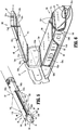
FIG. 5 is a side, perspective view of a jaw assembly for use with the surgical stapling apparatus ofFIG. 1 , in accordance with another embodiment of the present disclosure; and -
FIG. 6 is an end, perspective view of the jaw assembly ofFIG. 5 , including surgical buttresses releasably secured to anvil and staple cartridge assemblies of the jaw assembly via retention members in accordance with another embodiment of the present disclosure. - Various exemplary embodiments of the present disclosure are discussed herein below in terms of surgical buttress retention systems for releasably securing surgical buttresses to a surgical stapling apparatus. The surgical buttresses described herein may be used in sealing a wound by approximating the edges of wound tissue between a staple cartridge assembly and an anvil assembly of a surgical stapling apparatus which includes at least one surgical buttress. The surgical buttress is releasably attached to the surgical stapling apparatus by a surgical buttress retention system that is configured to secure both proximal and distal portions of the surgical buttress to the surgical stapling apparatus and to release both the proximal and distal portions of the surgical buttress from the surgical stapling apparatus during cutting of only the proximal portion of the surgical buttress during firing of the surgical stapling apparatus.
- Embodiments of the presently disclosed surgical buttress retention systems will now be described in detail with reference to the drawing figures wherein like reference numerals identify similar or identical elements. Throughout this description, the term "proximal" refers to a portion of a structure, or component thereof, that is closer to a user, and the term "distal" refers to a portion of the structure, or component thereof, that is farther from the user. Directional reference terms, such as "top," "bottom," "side," and the like, are intended to ease description of the embodiments and are not intended to have any limiting effect on the ultimate orientations of a structure or any parts thereof.
- Referring now to
FIGS. 1 and 2 , an exemplary surgical stapling apparatus orsurgical stapler 1 is shown for use in stapling tissue and applying one or more buttress materials or surgical buttresses to the tissue. Thesurgical stapling apparatus 1 generally includes ahandle assembly 10, an elongatetubular body portion 20 extending distally from thehandle assembly 10, and an end effector orjaw assembly 30 extending distally from the elongatetubular body portion 20. Thejaw assembly 30 includes ananvil assembly 40 and astaple cartridge assembly 50. Thejaw assembly 30 may be permanently affixed to the elongatetubular body portion 20 or may be detachable with respect to the elongatetubular body portion 20 and thus, replaceable with anew jaw assembly 30. Theanvil assembly 40 and/or thestaple cartridge assembly 50 is pivotable with respect to the elongatetubular body portion 20 such that the anvil andstaple cartridge assemblies staple cartridge assemblies staple cartridge assemblies - The
handle assembly 10 includes astationary handle member 12a, amovable handle member 12b, and abarrel portion 14. Anarticulation lever 16 is mounted on the forward end of thebarrel portion 14 to facilitate articulation of thejaw assembly 30. Arotatable member 18 is also mounted on the forward end of thebarrel portion 14, adjacent thearticulation lever 16. Rotation of therotatable member 18 relative to thebarrel portion 14 rotates the elongatetubular body portion 20 and thejaw assembly 30 relative to thehandle assembly 10 so as to properly orient the anvil andstaple cartridge assemblies knobs 19 is movably positionable along thebarrel portion 14. The pair ofknobs 19 is advanced distally to approximate or close the anvil andstaple cartridge assemblies staple cartridge assemblies movable handle member 12b applies lines of staples 58 (FIG. 3 ) to tissue captured between the anvil andstaple cartridge assemblies - As seen in
FIG. 3 , theanvil assembly 40 includes ananvil plate 42 having a centrallongitudinal slot 41 formed therein, and acover plate 44 secured over theanvil plate 42 such that thecover plate 44 defines a top or outwardly facingsurface 46 of theanvil assembly 40. Theanvil plate 42 may include a plurality of staple forming pockets/cavities (not shown) defined in an inward ortissue facing surface 48 thereof. - The
staple cartridge assembly 50 includes acartridge carrier 52 defining anelongated support channel 53 configured and dimensioned to selectively receive astaple cartridge 54 therein. Thestaple cartridge 54 is removable and replaceable in thecartridge carrier 52 of thestaple cartridge assembly 50. Thestaple cartridge 54 includes an inward ortissue facing surface 56 defining staple pockets orretention slots 55 formed therein for receiving a plurality of fasteners orstaples 58 andstaple pushers 60. A centrallongitudinal slot 57 is formed in and extends along a substantial length of thestaple cartridge 54 to facilitate passage of aknife blade 62 of adrive bar 64 therethrough. During operation of thesurgical stapler 1, anactuation sled 66 translates through thestaple cartridge 54 to advancecam wedges 68 of theactuation sled 66 into sequential contact with thestaple pushers 60, to cause thestaple pushers 60 to translate vertically within the staple pockets 55 and urge thestaples 58 from the staple pockets 55 towards thetissue facing surface 48 of theanvil plate 42 of theanvil assembly 40. - For a detailed description of the structure and function of exemplary surgical stapling apparatus, reference may be made to
U.S. Patent Nos. 6,330,965 ,6,241,139 , and7,819,896 , the entire contents of each of which are incorporated herein by reference. It should be appreciated that principles of the present disclosure are equally applicable to surgical stapling apparatus having other configurations such as, for example, the types described inU.S. Patent Nos. 7,128,253 ,7,334,717 , and5,964,394 , the entire contents of each of which are incorporated herein by reference. Accordingly, it should be understood that a variety of surgical stapling apparatus may be utilized with the surgical buttress retention systems of the present disclosure. For example, laparoscopic or open staplers, such as, for example, GIA™, Endo GIA™, TA™, and Endo TA™ staplers and/or linear and radial reloads with, for example, Tri-Staple™ technology, available through Medtronic (North Haven, CT) may be utilized with the surgical buttress retention systems of the present disclosure. - With continued reference to
FIG. 3 , theanvil assembly 40 further includes proximalanvil guide slots 43, distalanvil guide slots 45, and ananvil plug 47. The proximalanvil guide slots 43 and the distalanvil guide slots 45 are recessed in theouter surface 46 of theanvil cover 44. The proximalanvil guide slots 43 are disposed in opposed sides of theanvil cover 44, and are mirror images of each other. The proximalanvil guide slots 43 have a generally U-shaped configuration in that each of the proximalanvil guide slots 43 include acentral segment 43b extending longitudinally along theanvil cover 44 and a first orproximal leg segment 43a and a second ordistal leg segment 43c each extending at an angle with respect to thecentral segment 43b toside edges anvil cover 44. The first andsecond leg segments central segment 43b. In embodiments, thefirst leg segment 43a is disposed at about a 90° angle with respect to thecentral segment 43b and thesecond leg segment 43c is disposed at about a 135° angle with respect to thecentral segment 43b. In some embodiments, as shown inFIG. 2 , thefirst leg segment 43a is disposed at about a 90° angle with respect to thecentral segment 43b and thesecond leg segment 43c' is disposed at about a 90° angle with respect to thecentral segment 43b. Theanvil plate 42 may includerecesses 42c defined inside edges second leg segments anvil guide slots 43. - The distal
anvil guide slots 45 are disposed in opposed sides of theanvil cover 44 in longitudinally spaced relation relative to the proximalanvil guide slots 43, and are also mirror images of each other. The distalanvil guide slots 45 have a generally L-shaped configuration in that each of the distalanvil guide slots 45 have first andsecond leg segments first leg segment 45a is disposed at about a 135° angle with respect to thesecond leg segment 45b which extends longitudinally along theanvil cover 44 to adistal end 44c thereof. In some embodiments, as shown inFIG. 2 , thefirst leg segment 45a' is disposed at about a 90° angle with respect to thesecond leg segment 45b which extends longitudinally along theanvil cover 44 to thedistal end 44c thereof. - The
anvil plug 47 has a cylindrical body 47a that is configured to releasably engage thedistal end 44c of theanvil cover 44. In embodiments, theanvil plug 47 is press fit into ananvil recess 49 defined in thedistal end 44c of theanvil cover 44. Theanvil plug 47 may include an aperture 47b defined therethrough. - With continued reference to
FIG. 3 , thestaple cartridge assembly 50 further includes proximalcartridge guide slots 73, distalcartridge guide slots 75, and acartridge plug 77. The proximalcartridge guide slots 73 are recessed inside surfaces cartridge carrier 52, and the distalcartridge guide slots 77 are recessed in anouter surface 54a of thestaple cartridge 54. While only one of the proximal and distalcartridge guide slots FIG. 3 , it should be understood that the other of the proximal and distalcartridge guide slots respective cartridge carrier 52 andstaple cartridge 54 as mirror images of the ones shown. - The proximal
cartridge guide slots 73 have a generally U-shaped configuration in that each of the proximalcartridge guide slots 73 include acentral segment 73b extending longitudinally along thecartridge carrier 52 and a first orproximal leg segment 73a and a second ordistal leg segment 73c each extending at an angle with respect to thecentral segment 73b. The first andsecond leg segments central segment 73b. In embodiments, thefirst leg segment 73a is disposed at about a 90° angle with respect to thecentral segment 73b and thesecond leg segment 73c is disposed at about a 135° angle with respect to thecentral segment 73b. In some embodiments, as shown inFIG. 2 , thefirst leg segment 73a is disposed at about a 90° angle with respect to thecentral segment 73b and thesecond leg segment 73c' is disposed at about a 90° angle with respect to thecentral segment 73b. - The distal
cartridge guide slots 75 have a generally L-shaped configuration in that each of the distalcartridge guide slots 75 have first andsecond leg segments first leg segment 75a is disposed at about a 135° angle with respect to thesecond leg segment 75b which extends transversely across adistal portion 54b of thestaple cartridge 54. In some embodiments, as shown inFIG. 2 , thefirst leg segment 75a' is disposed at about a 90° angle with respect to thesecond leg segment 75b which extends transversely across thedistal portion 54b of thestaple cartridge 54. - The
cartridge plug 77 has acylindrical body 77a that is configured to releasably engage acartridge recess 51 defined in thedistal portion 54b of thestaple cartridge 54. In embodiments, thecartridge plug 77 is press fit into thecartridge recess 51 of thestaple cartridge 54. Thecartridge plug 77 may include anaperture 77b defined therethrough. - With reference now to
FIG. 4 ,surgical buttresses 110, 120 (also referred to herein as anvil buttress 110 and cartridge buttress 120) are releasably attached to the respective anvil andstaple cartridge assemblies jaw assembly 30 of the surgical stapler 1 (FIG. 1 ) byretention members anvil retention member 130a andcartridge retention member 130b). Thesurgical buttresses surgical buttresses surgical buttresses - The
surgical buttresses surgical buttresses surgical buttresses - Porous layer(s) in a surgical buttress may enhance the ability of the surgical buttress to absorb fluid, reduce bleeding, and seal a wound. Also, the porous layer(s) may allow for tissue ingrowth to fix the surgical buttress in place. Non-porous layer(s) in a surgical buttress may enhance the ability of the surgical buttress to resist tears and perforations during the manufacturing, shipping, handling, and stapling processes. Also, non-porous layer(s) may retard or prevent tissue ingrowth from surrounding tissues thereby acting as an adhesion barrier and preventing the formation of unwanted scar tissue.
- The
retention members retention members - With continued reference to
FIG. 4 , in conjunction withFIG. 3 , the anvil buttress 110 is releasably secured to theanvil assembly 40 via an anvil buttressretention system 80 including theanvil retention member 130a in cooperation with the proximal and distalanvil guide slots 43, 45 (FIG. 3 ) and theanvil plug 47 of theanvil assembly 40. With the anvil buttress 110 positioned on thetissue facing surface 48 of theanvil plate 42, a central orfirst portion 132a of theanvil retention member 130a is positioned across aproximal portion 110a of the anvil buttress 110 and aligned with thefirst leg segments 43a of the proximalanvil guide slots 43 such thatsecond portions 132b of theanvil retention member 130a are positioned within the proximalanvil guide slots 43. In embodiments in which thefirst leg segments 43a of the proximalanvil guide slots 43 are disposed at about a 90° angle with respect to thecentral segment 43b, thefirst portion 132a of theanvil retention member 130a will be retained transversely across theproximal portion 110a of the anvil buttress 110. -
Third portions 132c of theanvil retention member 130a extend from the proximalanvil guide slots 43 and cross each other over adistal portion 110b of the anvil buttress 110, andfourth portions 132d of theanvil retention member 130a are positioned within the distalanvil guide slots 45. In embodiments in which thesecond leg segments 43c of the proximalanvil guide slots 43 and thefirst leg segments 45a of the distalanvil guide slots 45 are disposed at about 135° angles, as described above, theanvil retention member 130a follows an aligned path for the cross over transition over thedistal portion 110b of the anvil buttress 110. Fifth orend portions 132e of theanvil retention member 130a are coupled to theanvil plug 47 to retain theanvil retention member 130a on theanvil assembly 40 and over the anvil buttress 110. - The
fifth portions 132e of theanvil retention member 130a may be wound around theanvil plug 47 to tension theanvil retention member 130a on theanvil assembly 40. Thefifth portions 132e may be wound around theanvil plug 47 prior to positioning theanvil plug 47 within theanvil recess 49 or while theanvil plug 47 is positioned within the anvil recess 49 (e.g., by rotating theanvil plug 47 relative to the anvil cover 44). In embodiments, thefifth portions 132e are passed into the aperture 47b of theanvil plug 47 and retained therein such that theanvil plug 47 may be rotated relative to theanvil cover 44 to tension theanvil retention member 130a about the anvil buttress 110 and theanvil assembly 40. - The configuration of the proximal and distal
anvil guide slots anvil retention member 130a therethrough minimizes and/or prevents pinch points along theanvil retention member 130a to allow for smooth insertion, tensioning, and deployment of theanvil retention member 130a. Moreover, the depth of the proximal and distalanvil guide slots anvil retention member 130a is flush with the outer surfaces of theanvil assembly 40 to reduce and/or eliminate the occurrence of theanvil retention member 130a moving out of alignment with the proximal and/or distalanvil guide slots anvil retention member 130a relative to theanvil assembly 40 during tensioning thereof and/or during insertion into tissue when outside forces may act upon thejaw assembly 30. - As also shown in
FIG. 4 , in conjunction withFIG. 3 , the cartridge buttress 120 is releasably secured to thestaple cartridge assembly 50 via a cartridge buttressretention system 90 including thecartridge retention member 130b in cooperation with the proximal and distalcartridge guide slots 73, 75 (FIG. 3 ), and thecartridge plug 77 of thestaple cartridge assembly 50. With the cartridge buttress 120 positioned on thetissue facing surface 56 of thestaple cartridge 54, a central orfirst portion 134a of thecartridge retention member 130b is positioned across aproximal portion 120a of the cartridge buttress 120 and aligned with thefirst leg segments 73a of the proximalcartridge guide slots 73 such thatsecond portions 134b of thecartridge retention member 130b are positioned within the proximalcartridge guide slots 73. In embodiments in which thefirst leg segments 73a of the proximalcartridge guide slots 73 are disposed at about a 90° angle with respect to thecentral segment 73b, thefirst portion 134a of thecartridge retention member 130b will be retained transversely across theproximal portion 120b of the cartridge buttress 120. -
Third portions 134c of thecartridge retention member 130b extend from the proximalcartridge guide slots 73 and cross each other over adistal portion 120b of the cartridge buttress 120, andfourth portions 134d of thecartridge retention member 130b are positioned within the distalcartridge guide slots 75. In embodiments in which thesecond leg segments 73c of the proximalcartridge guide slots 73 and thefirst leg segments 75a of the distalcartridge guide slots 75 are disposed at about 135° angles, as described above, the buttressretention member 130b follows an aligned path for the cross over transition over thedistal portion 120b of the cartridge buttress 120. Fifth orend portions 134e of thecartridge retention member 130b are coupled to thecartridge plug 77 to retain thecartridge retention member 130b on thestaple cartridge assembly 50 and over the cartridge buttress 120. - The
fifth portions 134e of thecartridge retention member 130b may be wound around thecartridge plug 77 to tension thecartridge retention member 130b on thestaple cartridge assembly 50. Thefifth portions 134e may be wound around thecartridge plug 77 prior to positioning thecartridge plug 77 within thecartridge recess 51 or while thecartridge plug 77 is positioned within the cartridge recess 51 (e.g., by rotating thecartridge plug 77 relative to the staple cartridge 54). In embodiments, thefifth portions 134e are passed through theaperture 77b of thecartridge plug 77 and retained therein such that thecartridge plug 77 may be rotated relative to thestaple cartridge 54 to tension thecartridge retention member 130b about the cartridge buttress 120 and thestaple cartridge assembly 50. - The configuration of the proximal and distal
cartridge guide slots cartridge retention member 130b therethrough minimizes and/or prevents pinch points along thecartridge retention member 130b to allow for smooth insertion, tensioning, and deployment of thecartridge retention member 130b. Moreover, the depth of the proximal and distalcartridge guide slots cartridge retention member 130b is flush with the outer surfaces of thestaple cartridge assembly 50 to reduce and/or eliminate the occurrence of thecartridge retention member 130b moving out of alignment with the proximal and/or distalcartridge guide slots cartridge retention member 130b relative to thestaple cartridge assembly 50 during tensioning thereof and/or during insertion into tissue when outside forces may act upon thejaw assembly 30. - In a method of loading the anvil and cartridge buttresses 110, 120 onto the anvil and
staple cartridge assemblies staple cartridge assemblies cartridge retention members cartridge plug members cartridge retention members cartridge plug members retention systems cartridge retention members cartridge retention members jaw assembly 30 is thus loaded and ready for use, as shown inFIG. 4 . - In operation, with the anvil and cartridge buttress 110, 120 loaded onto the anvil and
staple cartridge assemblies surgical stapler 1 is used in accordance with methods known by those skilled in the art. Once the anvil andstaple cartridge assemblies FIG. 4 , to the closed position, shown, for example, inFIG. 2 ), thesurgical stapler 1 is fired. In firing thesurgical stapler 1, thedrive bar 64 is advanced distally through thejaw assembly 30 urging thestaple pushers 60 upwardly which, in turn, drive thestaples 58 out of the staple pockets 55 and through the anvil and cartridge buttresses 110, 120 as well as the captured tissue, thereby stapling the anvil and cartridge buttresses 110, 120 to the tissue. - During firing, the
knife blade 62 of thedrive bar 64 travels distally while substantially simultaneously cutting and dividing the tissue and the anvil and cartridge buttresses 110, 120 disposed between the rows of now formedstaples 58. As thefirst portions cartridge retention members proximal portions longitudinal slots staple cartridge assemblies knife blade 62 also cuts through thefirst portions cartridge retention members first portions cartridge retention members cartridge retention members cartridge retention members staple cartridge assemblies - When firing is complete, after a partial or full firing stroke, and the anvil and
staple cartridge assemblies staple cartridge assemblies retention members staple cartridge assemblies 40, 50 (via the anvil and cartridge plugs 47, 77) and removed from the surgical site with the removal of thejaw assembly 30 therefrom. Accordingly, the anvil and cartridge buttresses 110, 120 are released from thesurgical stapler 1 after a partial or full firing stroke by requiring only a single proximal cut of the anvil andcartridge retention members cartridge retention members - With reference now to
FIGS. 5 and 6 , a jaw assembly 30' in accordance with another embodiment of the present disclosure is shown. The jaw assembly 30' has an anvil assembly 40' including ananvil plate 42 and an anvil cover 44', and a staple cartridge assembly 50' including a carrier cartridge 52' and astaple cartridge 54'. The jaw assembly 30' is substantially similar to thejaw assembly 30 and will be described in detail herein to the extent necessary to describe the differences in construction and operation thereof. - The anvil assembly 40' includes a proximal
anvil guide assembly 140, a distalanvil guide assembly 144, and ananvil plug 47. Theproximal guide assembly 140 includes proximal anvil guide cleats orbumpers 142a disposed on opposed sides of the anvil cover 44'. The proximalanvil guide cleats 142a protrude or extend from an outer surface 46' of the anvil cover 44'and have a rounded shape. Theproximal guide assembly 140 further includes distal anvil guide cleats orbumpers 142b disposed on opposed sides of the anvil cover 44' in longitudinally spaced and aligned relation relative to the proximalanvil guide cleats 142a. The distalanvil guide cleats 142b also protrude or extend from an outer surface 46' of the anvil cover 44' and have a rounded shape. The proximal and distalanvil guide cleats - The distal
anvil guide assembly 144 includes anvil guide shoulders 146 extending from the outer surface 46' of theanvil cover 44. The anvil guide shoulders 146 are disposed on opposed sides of the anvil cover 44' and are images of each other. The anvil guide shoulders 146 have a generally L-shaped or C-shaped configuration including soft, rounded edges. The anvil guide shoulders 146 may also be formed from a soft and/or flexible material. - The staple cartridge assembly 50' includes a proximal
cartridge guide assembly 150, a distalcartridge guide assembly 154, and acartridge plug 77. The proximalcartridge guide assembly 150 includes proximal and distal cartridge guide cleats orbumpers cartridge guide assembly 154 includes cartridge guideshoulders 156 disposed on opposed sides of thestaple cartridge 54'. While only one of the proximal and distalcartridge guide cleats shoulders 156 are shown, it should be understood that the other of the respective proximal and distalcartridge guide cleats shoulders 156, are substantially identical to the ones shown and are positioned on the opposing side of the cartridge carrier 52' andstaple cartridge 54' as mirror images of each other. - The proximal and distal
cartridge guide cleats side surfaces 52a', 52b' of the cartridge carrier 52', and each has a rounded shape. The distalcartridge guide cleats 152b are longitudinally spaced from, and aligned with, the proximalcartridge guide cleats 152a. The cartridge guide shoulders 156 extend from opposed sides of adistal portion 54b' of thestaple cartridge 54', and each has a generally L-shaped or C-shaped configuration including soft, rounded edges. The proximal and distalcartridge guide cleats - With continued reference to
FIGS. 5 and 6 , an anvil buttress 110 is releasably secured to the anvil assembly 40' via an anvil buttressretention system 180 including ananvil retention member 130a in cooperation with the proximal and distalanvil guide assemblies 140, 142, and theanvil plug 47 of the anvil assembly 40'. With the anvil buttress 110 positioned on the tissue facing surface 48 (FIG. 3 ) of theanvil plate 42, a central orfirst portion 132a of theanvil retention member 130a is positioned across aproximal portion 110a of the anvil buttress 110 and aligned with proximally facing sides of the proximalanvil guide cleats 142a such thatsecond portions 132b of theanvil retention member 130a extend around the proximalanvil guide cleats 142a, longitudinally across the outer surface 46' of the anvil cover 44', and around the distalanvil guide cleats 142b. -
Third portions 132c of theanvil retention member 130a extend from distally facing sides of the distalanvil guide cleats 142b and cross each other over adistal portion 110b of the anvil buttress 110.Fourth portions 132d of theanvil retention member 130a are positioned around the anvil guide shoulders 146, and fifth orend portions 132e of theanvil retention member 130a are coupled to theanvil plug 47 to retain theanvil retention member 130a on the anvil assembly 40' and over the anvil buttress 110, as described above. - The configuration of the proximal and distal
anvil guide cleats anvil retention member 130a therearound minimizes and/or prevents pinch points along theanvil retention member 130a to allow for smooth insertion, tensioning, and deployment of theanvil retention member 130a. - As also shown in
FIGS. 5 and 6 , a cartridge buttress 120 is releasably secured to the staple cartridge assembly 50' via a cartridge buttressretention system 190 including acartridge retention member 130b in cooperation with the proximal and distalcartridge guide assemblies 150, 152, and thecartridge plug 77 of the staple cartridge assembly 50'. With the cartridge buttress 120 positioned on the tissue facing surface 56 (FIG. 3 ) of thestaple cartridge 54', a central orfirst portion 134a of thecartridge retention member 130b is positioned across aproximal portion 120a of the cartridge buttress 120 and aligned with proximally facing sides of the proximalcartridge guide cleats 152a such thatsecond portions 134b of thecartridge retention member 130b extend around the proximalcartridge guide cleats 152a, longitudinally along the cartridge carrier 52', and around the distalcartridge guide cleats 152b. -
Third portions 134c of thecartridge retention member 130b extend from distally facing sides of the distalanvil guide cleats 152b and cross each other over adistal portion 120b of the cartridge buttress 120.Fourth portions 134d of thecartridge retention member 130b are positioned around the cartridge guide shoulders 156, and fifth orend portions 134e of thecartridge retention member 130b are coupled to thecartridge plug 77 to retain thecartridge retention member 130b on the staple cartridge assembly 50' and over the cartridge buttress 120, as described above. - The configuration of the proximal and distal
cartridge guide cleats cartridge retention member 130b therearound minimizes and/or prevents pinch points along thecartridge retention member 130b to allow for smooth insertion, tensioning, and deployment of thecartridge retention member 130b. - A
surgical stapler 1 including the jaw assembly 30' having anvil and cartridge buttresses 110, 120 loaded onto the anvil and staple cartridge assemblies 40', 50' via the anvil and cartridge buttressretention systems surgical stapler 1 including thejaw assembly 30 having anvil and cartridge buttresses 110, 120 loaded onto the anvil andstaple cartridge assemblies retention systems - It should be understood that the anvil buttress
retention systems retention systems anvil guide slots 43 of the anvil buttressretention system 80 may be used with the proximal and distalanvil guide cleats retention system 180, and/or the distalanvil guide slots 45 of the anvil buttressretention system 80 may be used with the anvil guide shoulders 146 of the anvil buttressretention system 180. Similarly, the proximalcartridge guide slots 73 of the cartridge buttressretention system 90 may be used with the proximal and distalcartridge guide cleats retention system 190, and/or the distalcartridge guide slots 75 of the cartridge buttressretention system 90 may be used with the cartridge guide shoulders 156 of the cartridge buttressretention system 190. As another example, the proximal and distalanvil guide cleats retention system 180 may be used with thecentral segments 43b of the proximalanvil guide slots 43 of the anvil buttressretention system 80, and/or the anvil guide shoulders 146 of the anvil buttressretention system 180 may be used with thesecond leg segments 45b of the distalanvil guide slots 45 of the anvil buttressretention system 80. Similarly, the proximal and distalcartridge guide cleats retention system 190 may be used with thecentral segments 73b of the proximalcartridge guide slots 73 of the cartridge buttressretention system 90, and/or the cartridge guide shoulders 156 of the cartridge buttressretention system 190 may be used with thesecond leg segments 75b of the distalcartridge guide slots 75 of the cartridge buttressretention system 90. A variety of combinations of the components of the anvil and cartridge buttress retention systems are envisioned, provided such result in smooth insertion, tensioning, and deployment of the retention members, as described above. - It should be further understood that while the
surgical stapler 1 is shown including both the anvil and cartridge buttresses 110, 120, thesurgical stapler 1 may include only the anvil buttress 110 or the cartridge buttress 120 depending on, for example, the surgical application and/or desired placement of the buttress material relative to tissue as should be understood by those skilled in the art. The anvil buttress 110 and/or the cartridge buttress 120 may be pre-loaded (e.g., by the manufacturer) onto theanvil assembly 40, 40' and/orstaple cartridge assembly 50, 50' of thejaw assembly 30, 30'. Additional or replacement anvil buttresses 110 and/or cartridge buttresses 120 may be secured to therespective anvil assembly 40, 40' and/orstaple cartridge assembly 50, 50' as needed or desired. - The surgical buttresses and anvil buttress retention systems described herein may also be configured for use with other surgical apparatus, such as electromechanical surgical devices as described, for example, in
U.S. Patent Appl. Pub. Nos. 2015/0157320 and2015/0157321 , the entire contents of each of which are incorporated herein by reference. - Persons skilled in the art will understand that the systems, devices, and methods specifically described herein and illustrated in the accompanying figures are non-limiting exemplary embodiments, and that the description, disclosure, and figures should be construed merely exemplary of particular embodiments. It is to be understood, therefore, that the present disclosure is not limited to the precise embodiments described, and that various other changes and modifications may be effected by one skilled in the art without departing from the scope or spirit of the disclosure. Additionally, it is envisioned that the elements and features illustrated or described in connection with one exemplary embodiment may be combined with the elements and features of another exemplary embodiment without departing from the scope of the present disclosure, and that such modifications and variations are also intended to be included within the scope of the present disclosure. Accordingly, the subject matter of the present disclosure is not to be limited by what has been particularly shown and described.
- The invention may be described by reference to the following numbered paragraphs:-
- 1. A surgical stapling apparatus comprising:
- a jaw assembly including an anvil assembly and a staple cartridge assembly, at least one of the anvil and staple cartridge assemblies including a surgical buttress retention system; and
- a surgical buttress releasably secured to a tissue facing surface of the anvil assembly or the staple cartridge assembly via the surgical buttress retention system, the surgical buttress retention system including:
- proximal guide slots defined in opposed sides of the anvil assembly or the staple cartridge assembly and having a generally U-shaped configuration that are mirror images of each other;
- a plug coupled to a distal portion of the anvil assembly or the staple cartridge assembly; and
- a retention member including a central portion extending across a proximal portion of the surgical buttress, second portions positioned within the proximal guide slots, third portions extending across a distal portion of the surgical buttress, and end portions coupled to the plug.
- 2. The surgical stapling apparatus according to
paragraph 1, wherein the proximal guide slots have a central segment extending longitudinally along the anvil assembly or the staple cartridge assembly, and first and second leg segments each extending at an angle with respect to the central segment. - 3. The surgical stapling apparatus according to
paragraph 1, wherein the first leg segment is disposed at about a 90° angle with respect to the central segment. - 4. The surgical stapling apparatus according to paragraph 3, wherein the second leg segment is disposed at about a 90° angle with respect to the central segment.
- 5. The surgical stapling apparatus according to paragraph 3, wherein the second leg segment is disposed at about a 135° angle with respect to the central segment.
- 6. The surgical stapling apparatus according to
paragraph 1, wherein the plug is rotatable relative to the anvil assembly or the staple cartridge assembly to tension the retention member on the anvil assembly or the staple cartridge assembly. - 7. The surgical stapling apparatus according to
paragraph 1, wherein the plug includes an aperture defined therethrough that is configured to retain the end portions of the retention member. - 8. The surgical stapling apparatus according to
paragraph 1, wherein the surgical buttress retention system further includes distal guide slots defined in opposed sides of the anvil assembly or the staple cartridge assembly in longitudinally spaced relation relative to the proximal guide slots, the distal guide slots having a generally L-shaped configuration that are mirror images of each other, and wherein fourth portions of the retention member are positioned within the distal guide slots. - 9. The surgical stapling apparatus according to paragraph 8, wherein the distal guide slots each have first and second leg segments disposed at an angle with respect to each other.
- 10. The surgical stapling apparatus according to paragraph 9, wherein the first leg segment is disposed at about a 90° angle with respect to the second leg segment, and the second leg segment extends longitudinally along the anvil assembly or the staple cartridge assembly.
- 11. The surgical stapling apparatus according to paragraph 9, wherein the first leg segment is disposed at about a 135° angle with respect to the second leg segment, and the second leg segment extends longitudinally along the anvil assembly or the staple cartridge assembly.
- 12. The surgical stapling apparatus according to paragraph 8, wherein the third portions of the retention member cross each other over the distal portion of the surgical buttress.
- 13. The surgical stapling apparatus according to paragraph 8, wherein the surgical buttress retention system secures the surgical buttress to the anvil assembly, the anvil assembly including an anvil plate and an anvil cover secured over the anvil plate, the proximal and distal guide slots recessed in an outer surface of the anvil cover.
- 14. The surgical stapling apparatus according to paragraph 13, wherein the plug is press fit into an aperture defined in a distal end of the anvil cover.
- 15. The surgical stapling apparatus according to paragraph 8, wherein the surgical buttress retention system secures the surgical buttress to the staple cartridge assembly, the staple cartridge assembly including a staple cartridge disposed within a cartridge carrier, the proximal guide slots recessed in side surfaces of the cartridge carrier.
- 16. The surgical stapling apparatus according to paragraph 15, wherein the distal guide slots are recessed in an outer surface of the staple cartridge.
- 17. The surgical stapling apparatus according to paragraph 15, wherein the plug is press fit into an aperture defined in a distal portion of the staple cartridge.
- 18. A method of loading a surgical buttress onto a jaw assembly of a surgical stapling apparatus, the method comprising:
- placing a surgical buttress on a tissue facing surface of an anvil assembly or a staple cartridge assembly;
- positioning a central portion of a retaining member over a proximal portion of the surgical buttress;
- threading second portions of the retaining member through proximal guide slots disposed on opposed sides of the anvil assembly or the staple cartridge assembly;
- crossing third portions of the retaining member over a distal portion of the surgical buttress; and
- coupling end portions of the retaining member to a plug engaged with a distal portion of the anvil assembly or the staple cartridge assembly.
- 19. The method according to
paragraph 18, further comprising threading fourth portions of the retaining member through distal guide slots disposed on opposed sides of the anvil assembly or the staple cartridge assembly in longitudinally spaced relation relative to the proximal guide slots. - 20. The method according to
paragraph 18, further comprising rotating the plug to tension the retaining member on the anvil assembly or the staple cartridge assembly.
Claims (15)
- A surgical stapling apparatus comprising:a jaw assembly including an anvil assembly and a staple cartridge assembly, at least one of the anvil and staple cartridge assemblies including a surgical buttress retention system; anda surgical buttress releasably secured to a tissue facing surface of the anvil assembly or the staple cartridge assembly via the surgical buttress retention system, the surgical buttress retention system including:proximal guide slots defined in opposed sides of the anvil assembly or the staple cartridge assembly and having a generally U-shaped configuration that are mirror images of each other;a plug coupled to a distal portion of the anvil assembly or the staple cartridge assembly; anda retention member including a central portion extending across a proximal portion of the surgical buttress, second portions positioned within the proximal guide slots, third portions extending across a distal portion of the surgical buttress, and end portions coupled to the plug.
- The surgical stapling apparatus according to claim 1, wherein the proximal guide slots have a central segment extending longitudinally along the anvil assembly or the staple cartridge assembly, and first and second leg segments each extending at an angle with respect to the central segment.
- The surgical stapling apparatus according to claim 1 or claim 2, wherein the first leg segment is disposed at about a 90° angle with respect to the central segment.
- The surgical stapling apparatus according to claim 3, wherein the second leg segment is disposed at about a 90° angle with respect to the central segment. or wherein the second leg segment is disposed at about a 135° angle with respect to the central segment.
- The surgical stapling apparatus according to any preceding claim, wherein the plug is rotatable relative to the anvil assembly or the staple cartridge assembly to tension the retention member on the anvil assembly or the staple cartridge assembly; and/or wherein the plug includes an aperture defined therethrough that is configured to retain the end portions of the retention member.
- The surgical stapling apparatus according to any preceding claim, wherein the surgical buttress retention system further includes distal guide slots defined in opposed sides of the anvil assembly or the staple cartridge assembly in longitudinally spaced relation relative to the proximal guide slots, the distal guide slots having a generally L-shaped configuration that are mirror images of each other, and wherein fourth portions of the retention member are positioned within the distal guide slots; preferably wherein the distal guide slots each have first and second leg segments disposed at an angle with respect to each other.
- The surgical stapling apparatus according to claim 6, wherein the first leg segment is disposed at about a 90° angle with respect to the second leg segment, and the second leg segment extends longitudinally along the anvil assembly or the staple cartridge assembly or wherein the first leg segment is disposed at about a 135° angle with respect to the second leg segment, and the second leg segment extends longitudinally along the anvil assembly or the staple cartridge assembly.
- The surgical stapling apparatus according to claim 6, wherein the third portions of the retention member cross each other over the distal portion of the surgical buttress; and/or wherein the surgical buttress retention system secures the surgical buttress to the anvil assembly, the anvil assembly including an anvil plate and an anvil cover secured over the anvil plate, the proximal and distal guide slots recessed in an outer surface of the anvil cover.
- The surgical stapling apparatus according to claim 8, wherein the plug is press fit into an aperture defined in a distal end of the anvil cover.
- The surgical stapling apparatus according to claim 6, wherein the surgical buttress retention system secures the surgical buttress to the staple cartridge assembly, the staple cartridge assembly including a staple cartridge disposed within a cartridge carrier, the proximal guide slots recessed in side surfaces of the cartridge carrier.
- The surgical stapling apparatus according to claim 10, wherein the distal guide slots are recessed in an outer surface of the staple cartridge.
- The surgical stapling apparatus according to claim 10 or claim 11, wherein the plug is press fit into an aperture defined in a distal portion of the staple cartridge.
- A method of loading a surgical buttress onto a jaw assembly of a surgical stapling apparatus, the method comprising:placing a surgical buttress on a tissue facing surface of an anvil assembly or a staple cartridge assembly;positioning a central portion of a retaining member over a proximal portion of the surgical buttress;threading second portions of the retaining member through proximal guide slots disposed on opposed sides of the anvil assembly or the staple cartridge assembly;crossing third portions of the retaining member over a distal portion of the surgical buttress; andcoupling end portions of the retaining member to a plug engaged with a distal portion of the anvil assembly or the staple cartridge assembly.
- The method according to claim 13, further comprising threading fourth portions of the retaining member through distal guide slots disposed on opposed sides of the anvil assembly or the staple cartridge assembly in longitudinally spaced relation relative to the proximal guide slots.
- The method according to claim 13 or claim 14 further comprising rotating the plug to tension the retaining member on the anvil assembly or the staple cartridge assembly.
Applications Claiming Priority (2)
| Application Number | Priority Date | Filing Date | Title |
|---|---|---|---|
| US201762541970P | 2017-08-07 | 2017-08-07 | |
| US16/037,007 US10849625B2 (en) | 2017-08-07 | 2018-07-17 | Surgical buttress retention systems for surgical stapling apparatus |
Publications (2)
| Publication Number | Publication Date |
|---|---|
| EP3441011A1 true EP3441011A1 (en) | 2019-02-13 |
| EP3441011B1 EP3441011B1 (en) | 2020-04-01 |
Family
ID=63165305
Family Applications (1)
| Application Number | Title | Priority Date | Filing Date |
|---|---|---|---|
| EP18187602.0A Active EP3441011B1 (en) | 2017-08-07 | 2018-08-06 | Surgical buttress retention systems for surgical stapling apparatus |
Country Status (4)
| Country | Link |
|---|---|
| US (2) | US10849625B2 (en) |
| EP (1) | EP3441011B1 (en) |
| CN (1) | CN109381233B (en) |
| AU (1) | AU2018206827A1 (en) |
Cited By (2)
| Publication number | Priority date | Publication date | Assignee | Title |
|---|---|---|---|---|
| EP3909523A1 (en) * | 2020-05-12 | 2021-11-17 | Covidien LP | Surgical stapling device with replaceable staple cartridge |
| WO2023062478A1 (en) * | 2021-10-13 | 2023-04-20 | Covidien Lp | Surgical buttress attachment assemblies for surgical stapling apparatus |
Families Citing this family (306)
| Publication number | Priority date | Publication date | Assignee | Title |
|---|---|---|---|---|
| US20070084897A1 (en) | 2003-05-20 | 2007-04-19 | Shelton Frederick E Iv | Articulating surgical stapling instrument incorporating a two-piece e-beam firing mechanism |
| US9060770B2 (en) | 2003-05-20 | 2015-06-23 | Ethicon Endo-Surgery, Inc. | Robotically-driven surgical instrument with E-beam driver |
| US9072535B2 (en) | 2011-05-27 | 2015-07-07 | Ethicon Endo-Surgery, Inc. | Surgical stapling instruments with rotatable staple deployment arrangements |
| US11890012B2 (en) | 2004-07-28 | 2024-02-06 | Cilag Gmbh International | Staple cartridge comprising cartridge body and attached support |
| US7669746B2 (en) | 2005-08-31 | 2010-03-02 | Ethicon Endo-Surgery, Inc. | Staple cartridges for forming staples having differing formed staple heights |
| US10159482B2 (en) | 2005-08-31 | 2018-12-25 | Ethicon Llc | Fastener cartridge assembly comprising a fixed anvil and different staple heights |
| US7934630B2 (en) | 2005-08-31 | 2011-05-03 | Ethicon Endo-Surgery, Inc. | Staple cartridges for forming staples having differing formed staple heights |
| US11484312B2 (en) | 2005-08-31 | 2022-11-01 | Cilag Gmbh International | Staple cartridge comprising a staple driver arrangement |
| US11246590B2 (en) | 2005-08-31 | 2022-02-15 | Cilag Gmbh International | Staple cartridge including staple drivers having different unfired heights |
| US20070106317A1 (en) | 2005-11-09 | 2007-05-10 | Shelton Frederick E Iv | Hydraulically and electrically actuated articulation joints for surgical instruments |
| US8820603B2 (en) | 2006-01-31 | 2014-09-02 | Ethicon Endo-Surgery, Inc. | Accessing data stored in a memory of a surgical instrument |
| US7753904B2 (en) | 2006-01-31 | 2010-07-13 | Ethicon Endo-Surgery, Inc. | Endoscopic surgical instrument with a handle that can articulate with respect to the shaft |
| US11793518B2 (en) | 2006-01-31 | 2023-10-24 | Cilag Gmbh International | Powered surgical instruments with firing system lockout arrangements |
| US8708213B2 (en) | 2006-01-31 | 2014-04-29 | Ethicon Endo-Surgery, Inc. | Surgical instrument having a feedback system |
| US8186555B2 (en) | 2006-01-31 | 2012-05-29 | Ethicon Endo-Surgery, Inc. | Motor-driven surgical cutting and fastening instrument with mechanical closure system |
| US20120292367A1 (en) | 2006-01-31 | 2012-11-22 | Ethicon Endo-Surgery, Inc. | Robotically-controlled end effector |
| US7845537B2 (en) | 2006-01-31 | 2010-12-07 | Ethicon Endo-Surgery, Inc. | Surgical instrument having recording capabilities |
| US11278279B2 (en) | 2006-01-31 | 2022-03-22 | Cilag Gmbh International | Surgical instrument assembly |
| US11224427B2 (en) | 2006-01-31 | 2022-01-18 | Cilag Gmbh International | Surgical stapling system including a console and retraction assembly |
| US20110295295A1 (en) | 2006-01-31 | 2011-12-01 | Ethicon Endo-Surgery, Inc. | Robotically-controlled surgical instrument having recording capabilities |
| US8992422B2 (en) | 2006-03-23 | 2015-03-31 | Ethicon Endo-Surgery, Inc. | Robotically-controlled endoscopic accessory channel |
| US8322455B2 (en) | 2006-06-27 | 2012-12-04 | Ethicon Endo-Surgery, Inc. | Manually driven surgical cutting and fastening instrument |
| US10568652B2 (en) | 2006-09-29 | 2020-02-25 | Ethicon Llc | Surgical staples having attached drivers of different heights and stapling instruments for deploying the same |
| US11980366B2 (en) | 2006-10-03 | 2024-05-14 | Cilag Gmbh International | Surgical instrument |
| US8684253B2 (en) | 2007-01-10 | 2014-04-01 | Ethicon Endo-Surgery, Inc. | Surgical instrument with wireless communication between a control unit of a robotic system and remote sensor |
| US8840603B2 (en) | 2007-01-10 | 2014-09-23 | Ethicon Endo-Surgery, Inc. | Surgical instrument with wireless communication between control unit and sensor transponders |
| US11291441B2 (en) | 2007-01-10 | 2022-04-05 | Cilag Gmbh International | Surgical instrument with wireless communication between control unit and remote sensor |
| US8827133B2 (en) | 2007-01-11 | 2014-09-09 | Ethicon Endo-Surgery, Inc. | Surgical stapling device having supports for a flexible drive mechanism |
| US7673782B2 (en) | 2007-03-15 | 2010-03-09 | Ethicon Endo-Surgery, Inc. | Surgical stapling instrument having a releasable buttress material |
| US8931682B2 (en) | 2007-06-04 | 2015-01-13 | Ethicon Endo-Surgery, Inc. | Robotically-controlled shaft based rotary drive systems for surgical instruments |
| US11564682B2 (en) | 2007-06-04 | 2023-01-31 | Cilag Gmbh International | Surgical stapler device |
| US7753245B2 (en) | 2007-06-22 | 2010-07-13 | Ethicon Endo-Surgery, Inc. | Surgical stapling instruments |
| US11849941B2 (en) | 2007-06-29 | 2023-12-26 | Cilag Gmbh International | Staple cartridge having staple cavities extending at a transverse angle relative to a longitudinal cartridge axis |
| US11986183B2 (en) | 2008-02-14 | 2024-05-21 | Cilag Gmbh International | Surgical cutting and fastening instrument comprising a plurality of sensors to measure an electrical parameter |
| US7866527B2 (en) | 2008-02-14 | 2011-01-11 | Ethicon Endo-Surgery, Inc. | Surgical stapling apparatus with interlockable firing system |
| BRPI0901282A2 (en) | 2008-02-14 | 2009-11-17 | Ethicon Endo Surgery Inc | surgical cutting and fixation instrument with rf electrodes |
| US9179912B2 (en) | 2008-02-14 | 2015-11-10 | Ethicon Endo-Surgery, Inc. | Robotically-controlled motorized surgical cutting and fastening instrument |
| US8636736B2 (en) | 2008-02-14 | 2014-01-28 | Ethicon Endo-Surgery, Inc. | Motorized surgical cutting and fastening instrument |
| US7819298B2 (en) | 2008-02-14 | 2010-10-26 | Ethicon Endo-Surgery, Inc. | Surgical stapling apparatus with control features operable with one hand |
| US8573465B2 (en) | 2008-02-14 | 2013-11-05 | Ethicon Endo-Surgery, Inc. | Robotically-controlled surgical end effector system with rotary actuated closure systems |
| US20130153641A1 (en) | 2008-02-15 | 2013-06-20 | Ethicon Endo-Surgery, Inc. | Releasable layer of material and surgical end effector having the same |
| US9005230B2 (en) | 2008-09-23 | 2015-04-14 | Ethicon Endo-Surgery, Inc. | Motorized surgical instrument |
| US9386983B2 (en) | 2008-09-23 | 2016-07-12 | Ethicon Endo-Surgery, Llc | Robotically-controlled motorized surgical instrument |
| US11648005B2 (en) | 2008-09-23 | 2023-05-16 | Cilag Gmbh International | Robotically-controlled motorized surgical instrument with an end effector |
| US8210411B2 (en) | 2008-09-23 | 2012-07-03 | Ethicon Endo-Surgery, Inc. | Motor-driven surgical cutting instrument |
| US8608045B2 (en) | 2008-10-10 | 2013-12-17 | Ethicon Endo-Sugery, Inc. | Powered surgical cutting and stapling apparatus with manually retractable firing system |
| US8220688B2 (en) | 2009-12-24 | 2012-07-17 | Ethicon Endo-Surgery, Inc. | Motor-driven surgical cutting instrument with electric actuator directional control assembly |
| US8783543B2 (en) | 2010-07-30 | 2014-07-22 | Ethicon Endo-Surgery, Inc. | Tissue acquisition arrangements and methods for surgical stapling devices |
| US11298125B2 (en) | 2010-09-30 | 2022-04-12 | Cilag Gmbh International | Tissue stapler having a thickness compensator |
| US11812965B2 (en) | 2010-09-30 | 2023-11-14 | Cilag Gmbh International | Layer of material for a surgical end effector |
| US10405854B2 (en) | 2010-09-30 | 2019-09-10 | Ethicon Llc | Surgical stapling cartridge with layer retention features |
| US9839420B2 (en) | 2010-09-30 | 2017-12-12 | Ethicon Llc | Tissue thickness compensator comprising at least one medicament |
| US12213666B2 (en) | 2010-09-30 | 2025-02-04 | Cilag Gmbh International | Tissue thickness compensator comprising layers |
| US10945731B2 (en) | 2010-09-30 | 2021-03-16 | Ethicon Llc | Tissue thickness compensator comprising controlled release and expansion |
| US8746535B2 (en) | 2010-09-30 | 2014-06-10 | Ethicon Endo-Surgery, Inc. | Tissue thickness compensator comprising detachable portions |
| US9386988B2 (en) | 2010-09-30 | 2016-07-12 | Ethicon End-Surgery, LLC | Retainer assembly including a tissue thickness compensator |
| US9629814B2 (en) | 2010-09-30 | 2017-04-25 | Ethicon Endo-Surgery, Llc | Tissue thickness compensator configured to redistribute compressive forces |
| US11925354B2 (en) | 2010-09-30 | 2024-03-12 | Cilag Gmbh International | Staple cartridge comprising staples positioned within a compressible portion thereof |
| US8695866B2 (en) | 2010-10-01 | 2014-04-15 | Ethicon Endo-Surgery, Inc. | Surgical instrument having a power control circuit |
| BR112013027794B1 (en) | 2011-04-29 | 2020-12-15 | Ethicon Endo-Surgery, Inc | CLAMP CARTRIDGE SET |
| US11207064B2 (en) | 2011-05-27 | 2021-12-28 | Cilag Gmbh International | Automated end effector component reloading system for use with a robotic system |
| JP6105041B2 (en) | 2012-03-28 | 2017-03-29 | エシコン・エンド−サージェリィ・インコーポレイテッドEthicon Endo−Surgery,Inc. | Tissue thickness compensator containing capsules defining a low pressure environment |
| RU2014143258A (en) | 2012-03-28 | 2016-05-20 | Этикон Эндо-Серджери, Инк. | FABRIC THICKNESS COMPENSATOR CONTAINING MANY LAYERS |
| US9101358B2 (en) | 2012-06-15 | 2015-08-11 | Ethicon Endo-Surgery, Inc. | Articulatable surgical instrument comprising a firing drive |
| US9649111B2 (en) | 2012-06-28 | 2017-05-16 | Ethicon Endo-Surgery, Llc | Replaceable clip cartridge for a clip applier |
| US20140005678A1 (en) | 2012-06-28 | 2014-01-02 | Ethicon Endo-Surgery, Inc. | Rotary drive arrangements for surgical instruments |
| BR112014032776B1 (en) | 2012-06-28 | 2021-09-08 | Ethicon Endo-Surgery, Inc | SURGICAL INSTRUMENT SYSTEM AND SURGICAL KIT FOR USE WITH A SURGICAL INSTRUMENT SYSTEM |
| US20140001231A1 (en) | 2012-06-28 | 2014-01-02 | Ethicon Endo-Surgery, Inc. | Firing system lockout arrangements for surgical instruments |
| US11278284B2 (en) | 2012-06-28 | 2022-03-22 | Cilag Gmbh International | Rotary drive arrangements for surgical instruments |
| US12383267B2 (en) | 2012-06-28 | 2025-08-12 | Cilag Gmbh International | Robotically powered surgical device with manually-actuatable reversing system |
| US9289256B2 (en) | 2012-06-28 | 2016-03-22 | Ethicon Endo-Surgery, Llc | Surgical end effectors having angled tissue-contacting surfaces |
| US9700310B2 (en) | 2013-08-23 | 2017-07-11 | Ethicon Llc | Firing member retraction devices for powered surgical instruments |
| US9504470B2 (en) * | 2013-02-25 | 2016-11-29 | Covidien Lp | Circular stapling device with buttress |
| MX364729B (en) | 2013-03-01 | 2019-05-06 | Ethicon Endo Surgery Inc | Surgical instrument with a soft stop. |
| MX368026B (en) | 2013-03-01 | 2019-09-12 | Ethicon Endo Surgery Inc | Articulatable surgical instruments with conductive pathways for signal communication. |
| US9629629B2 (en) | 2013-03-14 | 2017-04-25 | Ethicon Endo-Surgey, LLC | Control systems for surgical instruments |
| US9649110B2 (en) | 2013-04-16 | 2017-05-16 | Ethicon Llc | Surgical instrument comprising a closing drive and a firing drive operated from the same rotatable output |
| BR112015026109B1 (en) | 2013-04-16 | 2022-02-22 | Ethicon Endo-Surgery, Inc | surgical instrument |
| JP6416260B2 (en) | 2013-08-23 | 2018-10-31 | エシコン エルエルシー | Firing member retractor for a powered surgical instrument |
| BR112016021943B1 (en) | 2014-03-26 | 2022-06-14 | Ethicon Endo-Surgery, Llc | SURGICAL INSTRUMENT FOR USE BY AN OPERATOR IN A SURGICAL PROCEDURE |
| US12232723B2 (en) | 2014-03-26 | 2025-02-25 | Cilag Gmbh International | Systems and methods for controlling a segmented circuit |
| US9743929B2 (en) | 2014-03-26 | 2017-08-29 | Ethicon Llc | Modular powered surgical instrument with detachable shaft assemblies |
| US9690362B2 (en) | 2014-03-26 | 2017-06-27 | Ethicon Llc | Surgical instrument control circuit having a safety processor |
| US20150297225A1 (en) | 2014-04-16 | 2015-10-22 | Ethicon Endo-Surgery, Inc. | Fastener cartridges including extensions having different configurations |
| JP6636452B2 (en) | 2014-04-16 | 2020-01-29 | エシコン エルエルシーEthicon LLC | Fastener cartridge including extension having different configurations |
| BR112016023825B1 (en) | 2014-04-16 | 2022-08-02 | Ethicon Endo-Surgery, Llc | STAPLE CARTRIDGE FOR USE WITH A SURGICAL STAPLER AND STAPLE CARTRIDGE FOR USE WITH A SURGICAL INSTRUMENT |
| US10426476B2 (en) | 2014-09-26 | 2019-10-01 | Ethicon Llc | Circular fastener cartridges for applying radially expandable fastener lines |
| BR112016023807B1 (en) | 2014-04-16 | 2022-07-12 | Ethicon Endo-Surgery, Llc | CARTRIDGE SET OF FASTENERS FOR USE WITH A SURGICAL INSTRUMENT |
| US10111679B2 (en) | 2014-09-05 | 2018-10-30 | Ethicon Llc | Circuitry and sensors for powered medical device |
| US11311294B2 (en) | 2014-09-05 | 2022-04-26 | Cilag Gmbh International | Powered medical device including measurement of closure state of jaws |
| BR112017004361B1 (en) | 2014-09-05 | 2023-04-11 | Ethicon Llc | ELECTRONIC SYSTEM FOR A SURGICAL INSTRUMENT |
| US10105142B2 (en) | 2014-09-18 | 2018-10-23 | Ethicon Llc | Surgical stapler with plurality of cutting elements |
| US11523821B2 (en) | 2014-09-26 | 2022-12-13 | Cilag Gmbh International | Method for creating a flexible staple line |
| US9924944B2 (en) | 2014-10-16 | 2018-03-27 | Ethicon Llc | Staple cartridge comprising an adjunct material |
| US11141153B2 (en) | 2014-10-29 | 2021-10-12 | Cilag Gmbh International | Staple cartridges comprising driver arrangements |
| US10517594B2 (en) | 2014-10-29 | 2019-12-31 | Ethicon Llc | Cartridge assemblies for surgical staplers |
| US9844376B2 (en) | 2014-11-06 | 2017-12-19 | Ethicon Llc | Staple cartridge comprising a releasable adjunct material |
| US10736636B2 (en) | 2014-12-10 | 2020-08-11 | Ethicon Llc | Articulatable surgical instrument system |
| US9987000B2 (en) | 2014-12-18 | 2018-06-05 | Ethicon Llc | Surgical instrument assembly comprising a flexible articulation system |
| US9844375B2 (en) | 2014-12-18 | 2017-12-19 | Ethicon Llc | Drive arrangements for articulatable surgical instruments |
| US9968355B2 (en) | 2014-12-18 | 2018-05-15 | Ethicon Llc | Surgical instruments with articulatable end effectors and improved firing beam support arrangements |
| US10085748B2 (en) | 2014-12-18 | 2018-10-02 | Ethicon Llc | Locking arrangements for detachable shaft assemblies with articulatable surgical end effectors |
| BR112017012996B1 (en) | 2014-12-18 | 2022-11-08 | Ethicon Llc | SURGICAL INSTRUMENT WITH AN ANvil WHICH IS SELECTIVELY MOVABLE ABOUT AN IMMOVABLE GEOMETRIC AXIS DIFFERENT FROM A STAPLE CARTRIDGE |
| US9844374B2 (en) | 2014-12-18 | 2017-12-19 | Ethicon Llc | Surgical instrument systems comprising an articulatable end effector and means for adjusting the firing stroke of a firing member |
| US11154301B2 (en) | 2015-02-27 | 2021-10-26 | Cilag Gmbh International | Modular stapling assembly |
| JP2020121162A (en) | 2015-03-06 | 2020-08-13 | エシコン エルエルシーEthicon LLC | Time dependent evaluation of sensor data to determine stability element, creep element and viscoelastic element of measurement |
| US9808246B2 (en) | 2015-03-06 | 2017-11-07 | Ethicon Endo-Surgery, Llc | Method of operating a powered surgical instrument |
| US10052044B2 (en) | 2015-03-06 | 2018-08-21 | Ethicon Llc | Time dependent evaluation of sensor data to determine stability, creep, and viscoelastic elements of measures |
| US10441279B2 (en) | 2015-03-06 | 2019-10-15 | Ethicon Llc | Multiple level thresholds to modify operation of powered surgical instruments |
| US9993248B2 (en) | 2015-03-06 | 2018-06-12 | Ethicon Endo-Surgery, Llc | Smart sensors with local signal processing |
| US10390825B2 (en) | 2015-03-31 | 2019-08-27 | Ethicon Llc | Surgical instrument with progressive rotary drive systems |
| US10238386B2 (en) | 2015-09-23 | 2019-03-26 | Ethicon Llc | Surgical stapler having motor control based on an electrical parameter related to a motor current |
| US10105139B2 (en) | 2015-09-23 | 2018-10-23 | Ethicon Llc | Surgical stapler having downstream current-based motor control |
| US10299878B2 (en) | 2015-09-25 | 2019-05-28 | Ethicon Llc | Implantable adjunct systems for determining adjunct skew |
| US11690623B2 (en) | 2015-09-30 | 2023-07-04 | Cilag Gmbh International | Method for applying an implantable layer to a fastener cartridge |
| US10736633B2 (en) | 2015-09-30 | 2020-08-11 | Ethicon Llc | Compressible adjunct with looping members |
| US11890015B2 (en) | 2015-09-30 | 2024-02-06 | Cilag Gmbh International | Compressible adjunct with crossing spacer fibers |
| US10265068B2 (en) | 2015-12-30 | 2019-04-23 | Ethicon Llc | Surgical instruments with separable motors and motor control circuits |
| US10292704B2 (en) | 2015-12-30 | 2019-05-21 | Ethicon Llc | Mechanisms for compensating for battery pack failure in powered surgical instruments |
| US11213293B2 (en) | 2016-02-09 | 2022-01-04 | Cilag Gmbh International | Articulatable surgical instruments with single articulation link arrangements |
| BR112018016098B1 (en) | 2016-02-09 | 2023-02-23 | Ethicon Llc | SURGICAL INSTRUMENT |
| US10448948B2 (en) | 2016-02-12 | 2019-10-22 | Ethicon Llc | Mechanisms for compensating for drivetrain failure in powered surgical instruments |
| US11224426B2 (en) | 2016-02-12 | 2022-01-18 | Cilag Gmbh International | Mechanisms for compensating for drivetrain failure in powered surgical instruments |
| US10828028B2 (en) | 2016-04-15 | 2020-11-10 | Ethicon Llc | Surgical instrument with multiple program responses during a firing motion |
| US10492783B2 (en) | 2016-04-15 | 2019-12-03 | Ethicon, Llc | Surgical instrument with improved stop/start control during a firing motion |
| US10357247B2 (en) | 2016-04-15 | 2019-07-23 | Ethicon Llc | Surgical instrument with multiple program responses during a firing motion |
| US11607239B2 (en) | 2016-04-15 | 2023-03-21 | Cilag Gmbh International | Systems and methods for controlling a surgical stapling and cutting instrument |
| US10426467B2 (en) | 2016-04-15 | 2019-10-01 | Ethicon Llc | Surgical instrument with detection sensors |
| US20170296173A1 (en) | 2016-04-18 | 2017-10-19 | Ethicon Endo-Surgery, Llc | Method for operating a surgical instrument |
| US11317917B2 (en) | 2016-04-18 | 2022-05-03 | Cilag Gmbh International | Surgical stapling system comprising a lockable firing assembly |
| US10433840B2 (en) | 2016-04-18 | 2019-10-08 | Ethicon Llc | Surgical instrument comprising a replaceable cartridge jaw |
| US10500000B2 (en) | 2016-08-16 | 2019-12-10 | Ethicon Llc | Surgical tool with manual control of end effector jaws |
| US10588630B2 (en) | 2016-12-21 | 2020-03-17 | Ethicon Llc | Surgical tool assemblies with closure stroke reduction features |
| JP6983893B2 (en) | 2016-12-21 | 2021-12-17 | エシコン エルエルシーEthicon LLC | Lockout configuration for surgical end effectors and replaceable tool assemblies |
| CN110114014B (en) | 2016-12-21 | 2022-08-09 | 爱惜康有限责任公司 | Surgical instrument system including end effector and firing assembly lockout |
| US10675026B2 (en) | 2016-12-21 | 2020-06-09 | Ethicon Llc | Methods of stapling tissue |
| MX2019007311A (en) | 2016-12-21 | 2019-11-18 | Ethicon Llc | Surgical stapling systems. |
| US10639035B2 (en) | 2016-12-21 | 2020-05-05 | Ethicon Llc | Surgical stapling instruments and replaceable tool assemblies thereof |
| US20180168625A1 (en) | 2016-12-21 | 2018-06-21 | Ethicon Endo-Surgery, Llc | Surgical stapling instruments with smart staple cartridges |
| US20180168615A1 (en) | 2016-12-21 | 2018-06-21 | Ethicon Endo-Surgery, Llc | Method of deforming staples from two different types of staple cartridges with the same surgical stapling instrument |
| US11419606B2 (en) | 2016-12-21 | 2022-08-23 | Cilag Gmbh International | Shaft assembly comprising a clutch configured to adapt the output of a rotary firing member to two different systems |
| US10918385B2 (en) | 2016-12-21 | 2021-02-16 | Ethicon Llc | Surgical system comprising a firing member rotatable into an articulation state to articulate an end effector of the surgical system |
| CN110114003A (en) | 2016-12-21 | 2019-08-09 | 爱惜康有限责任公司 | Surgical stapling system |
| JP7010956B2 (en) | 2016-12-21 | 2022-01-26 | エシコン エルエルシー | How to staple tissue |
| JP7010957B2 (en) | 2016-12-21 | 2022-01-26 | エシコン エルエルシー | Shaft assembly with lockout |
| US10603036B2 (en) | 2016-12-21 | 2020-03-31 | Ethicon Llc | Articulatable surgical instrument with independent pivotable linkage distal of an articulation lock |
| US10881399B2 (en) | 2017-06-20 | 2021-01-05 | Ethicon Llc | Techniques for adaptive control of motor velocity of a surgical stapling and cutting instrument |
| US11382638B2 (en) | 2017-06-20 | 2022-07-12 | Cilag Gmbh International | Closed loop feedback control of motor velocity of a surgical stapling and cutting instrument based on measured time over a specified displacement distance |
| US11653914B2 (en) | 2017-06-20 | 2023-05-23 | Cilag Gmbh International | Systems and methods for controlling motor velocity of a surgical stapling and cutting instrument according to articulation angle of end effector |
| US10779820B2 (en) | 2017-06-20 | 2020-09-22 | Ethicon Llc | Systems and methods for controlling motor speed according to user input for a surgical instrument |
| US11517325B2 (en) | 2017-06-20 | 2022-12-06 | Cilag Gmbh International | Closed loop feedback control of motor velocity of a surgical stapling and cutting instrument based on measured displacement distance traveled over a specified time interval |
| US10307170B2 (en) | 2017-06-20 | 2019-06-04 | Ethicon Llc | Method for closed loop control of motor velocity of a surgical stapling and cutting instrument |
| US11324503B2 (en) | 2017-06-27 | 2022-05-10 | Cilag Gmbh International | Surgical firing member arrangements |
| US11266405B2 (en) | 2017-06-27 | 2022-03-08 | Cilag Gmbh International | Surgical anvil manufacturing methods |
| US10993716B2 (en) | 2017-06-27 | 2021-05-04 | Ethicon Llc | Surgical anvil arrangements |
| US11564686B2 (en) | 2017-06-28 | 2023-01-31 | Cilag Gmbh International | Surgical shaft assemblies with flexible interfaces |
| BR112019027065B1 (en) | 2017-06-28 | 2023-12-26 | Ethicon Llc | SURGICAL INSTRUMENT AND SURGICAL SYSTEM |
| US11484310B2 (en) | 2017-06-28 | 2022-11-01 | Cilag Gmbh International | Surgical instrument comprising a shaft including a closure tube profile |
| EP3420947B1 (en) | 2017-06-28 | 2022-05-25 | Cilag GmbH International | Surgical instrument comprising selectively actuatable rotatable couplers |
| US10765427B2 (en) | 2017-06-28 | 2020-09-08 | Ethicon Llc | Method for articulating a surgical instrument |
| USD906355S1 (en) | 2017-06-28 | 2020-12-29 | Ethicon Llc | Display screen or portion thereof with a graphical user interface for a surgical instrument |
| US20190000459A1 (en) | 2017-06-28 | 2019-01-03 | Ethicon Llc | Surgical instruments with jaws constrained to pivot about an axis upon contact with a closure member that is parked in close proximity to the pivot axis |
| US10932772B2 (en) | 2017-06-29 | 2021-03-02 | Ethicon Llc | Methods for closed loop velocity control for robotic surgical instrument |
| US11471155B2 (en) | 2017-08-03 | 2022-10-18 | Cilag Gmbh International | Surgical system bailout |
| US11304695B2 (en) | 2017-08-03 | 2022-04-19 | Cilag Gmbh International | Surgical system shaft interconnection |
| US11944300B2 (en) | 2017-08-03 | 2024-04-02 | Cilag Gmbh International | Method for operating a surgical system bailout |
| US11974742B2 (en) | 2017-08-03 | 2024-05-07 | Cilag Gmbh International | Surgical system comprising an articulation bailout |
| US10849625B2 (en) | 2017-08-07 | 2020-12-01 | Covidien Lp | Surgical buttress retention systems for surgical stapling apparatus |
| US10912562B2 (en) * | 2017-08-14 | 2021-02-09 | Standard Bariatrics, Inc. | End effectors, surgical stapling devices, and methods of using same |
| US10743872B2 (en) | 2017-09-29 | 2020-08-18 | Ethicon Llc | System and methods for controlling a display of a surgical instrument |
| US11134944B2 (en) | 2017-10-30 | 2021-10-05 | Cilag Gmbh International | Surgical stapler knife motion controls |
| US10842490B2 (en) | 2017-10-31 | 2020-11-24 | Ethicon Llc | Cartridge body design with force reduction based on firing completion |
| US10779826B2 (en) | 2017-12-15 | 2020-09-22 | Ethicon Llc | Methods of operating surgical end effectors |
| US10835330B2 (en) | 2017-12-19 | 2020-11-17 | Ethicon Llc | Method for determining the position of a rotatable jaw of a surgical instrument attachment assembly |
| US11364027B2 (en) | 2017-12-21 | 2022-06-21 | Cilag Gmbh International | Surgical instrument comprising speed control |
| US12336705B2 (en) | 2017-12-21 | 2025-06-24 | Cilag Gmbh International | Continuous use self-propelled stapling instrument |
| US11311290B2 (en) | 2017-12-21 | 2022-04-26 | Cilag Gmbh International | Surgical instrument comprising an end effector dampener |
| US20200054321A1 (en) | 2018-08-20 | 2020-02-20 | Ethicon Llc | Surgical instruments with progressive jaw closure arrangements |
| US11324501B2 (en) | 2018-08-20 | 2022-05-10 | Cilag Gmbh International | Surgical stapling devices with improved closure members |
| US11207065B2 (en) | 2018-08-20 | 2021-12-28 | Cilag Gmbh International | Method for fabricating surgical stapler anvils |
| US11291440B2 (en) | 2018-08-20 | 2022-04-05 | Cilag Gmbh International | Method for operating a powered articulatable surgical instrument |
| US11241236B2 (en) * | 2018-09-21 | 2022-02-08 | Covidien Lp | Buttress attachment methods for circular EEA staplers |
| US11696761B2 (en) | 2019-03-25 | 2023-07-11 | Cilag Gmbh International | Firing drive arrangements for surgical systems |
| US11903581B2 (en) | 2019-04-30 | 2024-02-20 | Cilag Gmbh International | Methods for stapling tissue using a surgical instrument |
| US11648009B2 (en) | 2019-04-30 | 2023-05-16 | Cilag Gmbh International | Rotatable jaw tip for a surgical instrument |
| US11253254B2 (en) | 2019-04-30 | 2022-02-22 | Cilag Gmbh International | Shaft rotation actuator on a surgical instrument |
| US11452528B2 (en) | 2019-04-30 | 2022-09-27 | Cilag Gmbh International | Articulation actuators for a surgical instrument |
| US11471157B2 (en) | 2019-04-30 | 2022-10-18 | Cilag Gmbh International | Articulation control mapping for a surgical instrument |
| US11432816B2 (en) | 2019-04-30 | 2022-09-06 | Cilag Gmbh International | Articulation pin for a surgical instrument |
| US11426251B2 (en) | 2019-04-30 | 2022-08-30 | Cilag Gmbh International | Articulation directional lights on a surgical instrument |
| US11291451B2 (en) | 2019-06-28 | 2022-04-05 | Cilag Gmbh International | Surgical instrument with battery compatibility verification functionality |
| US11638587B2 (en) | 2019-06-28 | 2023-05-02 | Cilag Gmbh International | RFID identification systems for surgical instruments |
| US12004740B2 (en) | 2019-06-28 | 2024-06-11 | Cilag Gmbh International | Surgical stapling system having an information decryption protocol |
| US11259803B2 (en) | 2019-06-28 | 2022-03-01 | Cilag Gmbh International | Surgical stapling system having an information encryption protocol |
| US11660163B2 (en) | 2019-06-28 | 2023-05-30 | Cilag Gmbh International | Surgical system with RFID tags for updating motor assembly parameters |
| US11684434B2 (en) | 2019-06-28 | 2023-06-27 | Cilag Gmbh International | Surgical RFID assemblies for instrument operational setting control |
| US11298127B2 (en) | 2019-06-28 | 2022-04-12 | Cilag GmbH Interational | Surgical stapling system having a lockout mechanism for an incompatible cartridge |
| US11376098B2 (en) | 2019-06-28 | 2022-07-05 | Cilag Gmbh International | Surgical instrument system comprising an RFID system |
| US11771419B2 (en) | 2019-06-28 | 2023-10-03 | Cilag Gmbh International | Packaging for a replaceable component of a surgical stapling system |
| US11298132B2 (en) | 2019-06-28 | 2022-04-12 | Cilag GmbH Inlernational | Staple cartridge including a honeycomb extension |
| US11553971B2 (en) | 2019-06-28 | 2023-01-17 | Cilag Gmbh International | Surgical RFID assemblies for display and communication |
| US11426167B2 (en) | 2019-06-28 | 2022-08-30 | Cilag Gmbh International | Mechanisms for proper anvil attachment surgical stapling head assembly |
| US11361176B2 (en) | 2019-06-28 | 2022-06-14 | Cilag Gmbh International | Surgical RFID assemblies for compatibility detection |
| US11523822B2 (en) | 2019-06-28 | 2022-12-13 | Cilag Gmbh International | Battery pack including a circuit interrupter |
| US11627959B2 (en) | 2019-06-28 | 2023-04-18 | Cilag Gmbh International | Surgical instruments including manual and powered system lockouts |
| US11350938B2 (en) | 2019-06-28 | 2022-06-07 | Cilag Gmbh International | Surgical instrument comprising an aligned rfid sensor |
| US11246678B2 (en) | 2019-06-28 | 2022-02-15 | Cilag Gmbh International | Surgical stapling system having a frangible RFID tag |
| US11464601B2 (en) | 2019-06-28 | 2022-10-11 | Cilag Gmbh International | Surgical instrument comprising an RFID system for tracking a movable component |
| US11224497B2 (en) | 2019-06-28 | 2022-01-18 | Cilag Gmbh International | Surgical systems with multiple RFID tags |
| US11497492B2 (en) | 2019-06-28 | 2022-11-15 | Cilag Gmbh International | Surgical instrument including an articulation lock |
| US11478241B2 (en) | 2019-06-28 | 2022-10-25 | Cilag Gmbh International | Staple cartridge including projections |
| US11399837B2 (en) | 2019-06-28 | 2022-08-02 | Cilag Gmbh International | Mechanisms for motor control adjustments of a motorized surgical instrument |
| US11853835B2 (en) | 2019-06-28 | 2023-12-26 | Cilag Gmbh International | RFID identification systems for surgical instruments |
| US11576672B2 (en) | 2019-12-19 | 2023-02-14 | Cilag Gmbh International | Surgical instrument comprising a closure system including a closure member and an opening member driven by a drive screw |
| US11464512B2 (en) | 2019-12-19 | 2022-10-11 | Cilag Gmbh International | Staple cartridge comprising a curved deck surface |
| US11504122B2 (en) | 2019-12-19 | 2022-11-22 | Cilag Gmbh International | Surgical instrument comprising a nested firing member |
| US11931033B2 (en) | 2019-12-19 | 2024-03-19 | Cilag Gmbh International | Staple cartridge comprising a latch lockout |
| US11234698B2 (en) | 2019-12-19 | 2022-02-01 | Cilag Gmbh International | Stapling system comprising a clamp lockout and a firing lockout |
| US11446029B2 (en) | 2019-12-19 | 2022-09-20 | Cilag Gmbh International | Staple cartridge comprising projections extending from a curved deck surface |
| US11701111B2 (en) | 2019-12-19 | 2023-07-18 | Cilag Gmbh International | Method for operating a surgical stapling instrument |
| US12035913B2 (en) | 2019-12-19 | 2024-07-16 | Cilag Gmbh International | Staple cartridge comprising a deployable knife |
| US11304696B2 (en) | 2019-12-19 | 2022-04-19 | Cilag Gmbh International | Surgical instrument comprising a powered articulation system |
| US11529139B2 (en) | 2019-12-19 | 2022-12-20 | Cilag Gmbh International | Motor driven surgical instrument |
| US11529137B2 (en) | 2019-12-19 | 2022-12-20 | Cilag Gmbh International | Staple cartridge comprising driver retention members |
| US11911032B2 (en) | 2019-12-19 | 2024-02-27 | Cilag Gmbh International | Staple cartridge comprising a seating cam |
| US11291447B2 (en) | 2019-12-19 | 2022-04-05 | Cilag Gmbh International | Stapling instrument comprising independent jaw closing and staple firing systems |
| US11844520B2 (en) | 2019-12-19 | 2023-12-19 | Cilag Gmbh International | Staple cartridge comprising driver retention members |
| US11559304B2 (en) | 2019-12-19 | 2023-01-24 | Cilag Gmbh International | Surgical instrument comprising a rapid closure mechanism |
| US11607219B2 (en) | 2019-12-19 | 2023-03-21 | Cilag Gmbh International | Staple cartridge comprising a detachable tissue cutting knife |
| CN111528949B (en) * | 2020-05-08 | 2022-08-09 | 卓阮医疗科技(苏州)有限公司 | Anastomotic stoma reinforcing and repairing material |
| USD967421S1 (en) * | 2020-06-02 | 2022-10-18 | Cilag Gmbh International | Staple cartridge |
| USD966512S1 (en) * | 2020-06-02 | 2022-10-11 | Cilag Gmbh International | Staple cartridge |
| USD975850S1 (en) * | 2020-06-02 | 2023-01-17 | Cilag Gmbh International | Staple cartridge |
| USD975851S1 (en) * | 2020-06-02 | 2023-01-17 | Cilag Gmbh International | Staple cartridge |
| USD976401S1 (en) * | 2020-06-02 | 2023-01-24 | Cilag Gmbh International | Staple cartridge |
| USD974560S1 (en) * | 2020-06-02 | 2023-01-03 | Cilag Gmbh International | Staple cartridge |
| USD975278S1 (en) * | 2020-06-02 | 2023-01-10 | Cilag Gmbh International | Staple cartridge |
| US12220126B2 (en) | 2020-07-28 | 2025-02-11 | Cilag Gmbh International | Surgical instruments with double pivot articulation joint arrangements |
| US11896217B2 (en) | 2020-10-29 | 2024-02-13 | Cilag Gmbh International | Surgical instrument comprising an articulation lock |
| US11779330B2 (en) | 2020-10-29 | 2023-10-10 | Cilag Gmbh International | Surgical instrument comprising a jaw alignment system |
| US12053175B2 (en) | 2020-10-29 | 2024-08-06 | Cilag Gmbh International | Surgical instrument comprising a stowed closure actuator stop |
| US11844518B2 (en) | 2020-10-29 | 2023-12-19 | Cilag Gmbh International | Method for operating a surgical instrument |
| US11452526B2 (en) | 2020-10-29 | 2022-09-27 | Cilag Gmbh International | Surgical instrument comprising a staged voltage regulation start-up system |
| US11931025B2 (en) | 2020-10-29 | 2024-03-19 | Cilag Gmbh International | Surgical instrument comprising a releasable closure drive lock |
| USD1013170S1 (en) | 2020-10-29 | 2024-01-30 | Cilag Gmbh International | Surgical instrument assembly |
| US11617577B2 (en) | 2020-10-29 | 2023-04-04 | Cilag Gmbh International | Surgical instrument comprising a sensor configured to sense whether an articulation drive of the surgical instrument is actuatable |
| US11717289B2 (en) | 2020-10-29 | 2023-08-08 | Cilag Gmbh International | Surgical instrument comprising an indicator which indicates that an articulation drive is actuatable |
| USD980425S1 (en) | 2020-10-29 | 2023-03-07 | Cilag Gmbh International | Surgical instrument assembly |
| US11517390B2 (en) | 2020-10-29 | 2022-12-06 | Cilag Gmbh International | Surgical instrument comprising a limited travel switch |
| US11534259B2 (en) | 2020-10-29 | 2022-12-27 | Cilag Gmbh International | Surgical instrument comprising an articulation indicator |
| US11653915B2 (en) | 2020-12-02 | 2023-05-23 | Cilag Gmbh International | Surgical instruments with sled location detection and adjustment features |
| US11890010B2 (en) | 2020-12-02 | 2024-02-06 | Cllag GmbH International | Dual-sided reinforced reload for surgical instruments |
| US11678882B2 (en) | 2020-12-02 | 2023-06-20 | Cilag Gmbh International | Surgical instruments with interactive features to remedy incidental sled movements |
| US11627960B2 (en) | 2020-12-02 | 2023-04-18 | Cilag Gmbh International | Powered surgical instruments with smart reload with separately attachable exteriorly mounted wiring connections |
| US12471982B2 (en) | 2020-12-02 | 2025-11-18 | Cilag Gmbh International | Method for tissue treatment by surgical instrument |
| US11849943B2 (en) | 2020-12-02 | 2023-12-26 | Cilag Gmbh International | Surgical instrument with cartridge release mechanisms |
| US11653920B2 (en) | 2020-12-02 | 2023-05-23 | Cilag Gmbh International | Powered surgical instruments with communication interfaces through sterile barrier |
| US11944296B2 (en) | 2020-12-02 | 2024-04-02 | Cilag Gmbh International | Powered surgical instruments with external connectors |
| US11737751B2 (en) | 2020-12-02 | 2023-08-29 | Cilag Gmbh International | Devices and methods of managing energy dissipated within sterile barriers of surgical instrument housings |
| US11744581B2 (en) | 2020-12-02 | 2023-09-05 | Cilag Gmbh International | Powered surgical instruments with multi-phase tissue treatment |
| US11696757B2 (en) | 2021-02-26 | 2023-07-11 | Cilag Gmbh International | Monitoring of internal systems to detect and track cartridge motion status |
| US11744583B2 (en) | 2021-02-26 | 2023-09-05 | Cilag Gmbh International | Distal communication array to tune frequency of RF systems |
| US11730473B2 (en) | 2021-02-26 | 2023-08-22 | Cilag Gmbh International | Monitoring of manufacturing life-cycle |
| US11925349B2 (en) | 2021-02-26 | 2024-03-12 | Cilag Gmbh International | Adjustment to transfer parameters to improve available power |
| US11749877B2 (en) | 2021-02-26 | 2023-09-05 | Cilag Gmbh International | Stapling instrument comprising a signal antenna |
| US11723657B2 (en) | 2021-02-26 | 2023-08-15 | Cilag Gmbh International | Adjustable communication based on available bandwidth and power capacity |
| US11950779B2 (en) | 2021-02-26 | 2024-04-09 | Cilag Gmbh International | Method of powering and communicating with a staple cartridge |
| US11793514B2 (en) | 2021-02-26 | 2023-10-24 | Cilag Gmbh International | Staple cartridge comprising sensor array which may be embedded in cartridge body |
| US11701113B2 (en) | 2021-02-26 | 2023-07-18 | Cilag Gmbh International | Stapling instrument comprising a separate power antenna and a data transfer antenna |
| US11980362B2 (en) | 2021-02-26 | 2024-05-14 | Cilag Gmbh International | Surgical instrument system comprising a power transfer coil |
| US11950777B2 (en) | 2021-02-26 | 2024-04-09 | Cilag Gmbh International | Staple cartridge comprising an information access control system |
| US11812964B2 (en) | 2021-02-26 | 2023-11-14 | Cilag Gmbh International | Staple cartridge comprising a power management circuit |
| US12108951B2 (en) | 2021-02-26 | 2024-10-08 | Cilag Gmbh International | Staple cartridge comprising a sensing array and a temperature control system |
| US11751869B2 (en) | 2021-02-26 | 2023-09-12 | Cilag Gmbh International | Monitoring of multiple sensors over time to detect moving characteristics of tissue |
| US12324580B2 (en) | 2021-02-26 | 2025-06-10 | Cilag Gmbh International | Method of powering and communicating with a staple cartridge |
| US11759202B2 (en) | 2021-03-22 | 2023-09-19 | Cilag Gmbh International | Staple cartridge comprising an implantable layer |
| US11737749B2 (en) | 2021-03-22 | 2023-08-29 | Cilag Gmbh International | Surgical stapling instrument comprising a retraction system |
| US11826012B2 (en) | 2021-03-22 | 2023-11-28 | Cilag Gmbh International | Stapling instrument comprising a pulsed motor-driven firing rack |
| US11806011B2 (en) | 2021-03-22 | 2023-11-07 | Cilag Gmbh International | Stapling instrument comprising tissue compression systems |
| US11717291B2 (en) | 2021-03-22 | 2023-08-08 | Cilag Gmbh International | Staple cartridge comprising staples configured to apply different tissue compression |
| US11723658B2 (en) | 2021-03-22 | 2023-08-15 | Cilag Gmbh International | Staple cartridge comprising a firing lockout |
| US11826042B2 (en) | 2021-03-22 | 2023-11-28 | Cilag Gmbh International | Surgical instrument comprising a firing drive including a selectable leverage mechanism |
| US11832816B2 (en) | 2021-03-24 | 2023-12-05 | Cilag Gmbh International | Surgical stapling assembly comprising nonplanar staples and planar staples |
| US11786239B2 (en) | 2021-03-24 | 2023-10-17 | Cilag Gmbh International | Surgical instrument articulation joint arrangements comprising multiple moving linkage features |
| US11944336B2 (en) | 2021-03-24 | 2024-04-02 | Cilag Gmbh International | Joint arrangements for multi-planar alignment and support of operational drive shafts in articulatable surgical instruments |
| US11786243B2 (en) | 2021-03-24 | 2023-10-17 | Cilag Gmbh International | Firing members having flexible portions for adapting to a load during a surgical firing stroke |
| US11849945B2 (en) | 2021-03-24 | 2023-12-26 | Cilag Gmbh International | Rotary-driven surgical stapling assembly comprising eccentrically driven firing member |
| US11896219B2 (en) | 2021-03-24 | 2024-02-13 | Cilag Gmbh International | Mating features between drivers and underside of a cartridge deck |
| US11793516B2 (en) | 2021-03-24 | 2023-10-24 | Cilag Gmbh International | Surgical staple cartridge comprising longitudinal support beam |
| US11903582B2 (en) | 2021-03-24 | 2024-02-20 | Cilag Gmbh International | Leveraging surfaces for cartridge installation |
| US12102323B2 (en) | 2021-03-24 | 2024-10-01 | Cilag Gmbh International | Rotary-driven surgical stapling assembly comprising a floatable component |
| US11857183B2 (en) | 2021-03-24 | 2024-01-02 | Cilag Gmbh International | Stapling assembly components having metal substrates and plastic bodies |
| US11849944B2 (en) | 2021-03-24 | 2023-12-26 | Cilag Gmbh International | Drivers for fastener cartridge assemblies having rotary drive screws |
| US11896218B2 (en) | 2021-03-24 | 2024-02-13 | Cilag Gmbh International | Method of using a powered stapling device |
| US11744603B2 (en) | 2021-03-24 | 2023-09-05 | Cilag Gmbh International | Multi-axis pivot joints for surgical instruments and methods for manufacturing same |
| US20220378425A1 (en) | 2021-05-28 | 2022-12-01 | Cilag Gmbh International | Stapling instrument comprising a control system that controls a firing stroke length |
| US11801052B2 (en) * | 2021-08-30 | 2023-10-31 | Covidien Lp | Assemblies for surgical stapling instruments |
| WO2023034616A1 (en) * | 2021-09-03 | 2023-03-09 | Lexington Medical, Inc. | Staple line surgical buttress |
| US11957337B2 (en) | 2021-10-18 | 2024-04-16 | Cilag Gmbh International | Surgical stapling assembly with offset ramped drive surfaces |
| US11877745B2 (en) | 2021-10-18 | 2024-01-23 | Cilag Gmbh International | Surgical stapling assembly having longitudinally-repeating staple leg clusters |
| US12239317B2 (en) | 2021-10-18 | 2025-03-04 | Cilag Gmbh International | Anvil comprising an arrangement of forming pockets proximal to tissue stop |
| US11980363B2 (en) | 2021-10-18 | 2024-05-14 | Cilag Gmbh International | Row-to-row staple array variations |
| US12089841B2 (en) | 2021-10-28 | 2024-09-17 | Cilag CmbH International | Staple cartridge identification systems |
| US11937816B2 (en) | 2021-10-28 | 2024-03-26 | Cilag Gmbh International | Electrical lead arrangements for surgical instruments |
| US12432790B2 (en) | 2021-10-28 | 2025-09-30 | Cilag Gmbh International | Method and device for transmitting UART communications over a security short range wireless communication |
| CN118750070B (en) * | 2024-07-25 | 2025-01-24 | 乔伟 | Anastomotic reinforcement component device and stapler component for minimally invasive surgery |
Citations (10)
| Publication number | Priority date | Publication date | Assignee | Title |
|---|---|---|---|---|
| WO1997001989A1 (en) * | 1995-07-03 | 1997-01-23 | Frater Dirk A | System for mounting bolster material on tissue staplers |
| US5964394A (en) | 1996-03-15 | 1999-10-12 | United States Surgical Corporation | Surgical fastener applying device |
| US6241139B1 (en) | 1997-09-23 | 2001-06-05 | Keith L. Milliman | Surgical stapling apparatus |
| US7128253B2 (en) | 1995-08-28 | 2006-10-31 | United States Surgical Corporation | Surgical stapler |
| US7334717B2 (en) | 2001-10-05 | 2008-02-26 | Tyco Healthcare Group Lp | Surgical fastener applying apparatus |
| WO2009143331A1 (en) * | 2008-05-21 | 2009-11-26 | Cook Biotech Incorporated | Devices and methods for applying bolster materials to surgical fastening apparatuses |
| US7819896B2 (en) | 2002-10-04 | 2010-10-26 | Tyco Healthcare Group Lp | Tool assembly for a surgical stapling device |
| US20120234900A1 (en) * | 2011-03-15 | 2012-09-20 | Ethicon Endo-Surgery, Inc. | Surgical staple cartridges with tissue tethers for manipulating divided tissue and methods of using same |
| EP2730235A1 (en) * | 2012-11-09 | 2014-05-14 | Covidien LP | Surgical stapling apparatus including buttress attachment |
| US20150157321A1 (en) | 2013-12-09 | 2015-06-11 | Covidien Lp | Adapter assembly for interconnecting electromechanical surgical devices and surgical loading units, and surgical systems thereof |
Family Cites Families (367)
| Publication number | Priority date | Publication date | Assignee | Title |
|---|---|---|---|---|
| US3124136A (en) | 1964-03-10 | Method of repairing body tissue | ||
| DE1602563U (en) | 1949-08-01 | 1950-03-02 | Lebrecht Langenohl | S-FOERMIGER, SPRING BREAKER FOR CLEANING TOBACCO PIPE HEADS. |
| US3054406A (en) | 1958-10-17 | 1962-09-18 | Phillips Petroleum Co | Surgical mesh |
| US3079606A (en) | 1960-01-04 | 1963-03-05 | Bobrov Boris Sergeevich | Instrument for placing lateral gastrointestinal anastomoses |
| US3364200A (en) | 1960-03-28 | 1968-01-16 | Johnson & Johnson | Oxidized cellulose product and method for preparing the same |
| US3490675A (en) | 1966-10-10 | 1970-01-20 | United States Surgical Corp | Instrument for placing lateral gastrointestinal anastomoses |
| US3499591A (en) | 1967-06-23 | 1970-03-10 | United States Surgical Corp | Instrument for placing lateral gastro-intestinal anastomoses |
| US3797494A (en) | 1969-04-01 | 1974-03-19 | Alza Corp | Bandage for the administration of drug by controlled metering through microporous materials |
| DE2415728A1 (en) | 1973-04-13 | 1975-01-02 | Teijin Ltd | CARRIER FOR LIQUID LIGHT-SENSITIVE RESIN |
| US3939068A (en) | 1973-12-06 | 1976-02-17 | The United States Of America As Represented By The Secretary Of The Army | Process for treating waste water containing cellulose nitrate particles |
| US4064062A (en) | 1975-12-15 | 1977-12-20 | Colgate-Palmolive | Stabilized activated percompound bleaching compositions and methods for manufacture thereof |
| US4416698A (en) | 1977-07-26 | 1983-11-22 | Akzona Incorporated | Shaped cellulose article prepared from a solution containing cellulose dissolved in a tertiary amine N-oxide solvent and a process for making the article |
| US4166800A (en) | 1977-08-25 | 1979-09-04 | Sandoz, Inc. | Processes for preparation of microspheres |
| US4282236A (en) | 1979-11-07 | 1981-08-04 | Beecham Group Limited | β-Lactam antibacterial agents, their use in pharmaceutical compositions, and intermediates |
| US4429695A (en) | 1980-02-05 | 1984-02-07 | United States Surgical Corporation | Surgical instruments |
| US4347847A (en) | 1980-06-06 | 1982-09-07 | Usher Francis C | Method of hernia repair |
| US4452245A (en) | 1980-06-06 | 1984-06-05 | Usher Francis C | Surgical mesh and method |
| US4354628A (en) | 1980-09-29 | 1982-10-19 | United States Surgical Corporation | Surgical stapler apparatus having pivotally related staple holder and anvil |
| US4605730A (en) | 1982-10-01 | 1986-08-12 | Ethicon, Inc. | Surgical articles of copolymers of glycolide and ε-caprolactone and methods of producing the same |
| US4633873A (en) | 1984-04-26 | 1987-01-06 | American Cyanamid Company | Surgical repair mesh |
| US4626253A (en) | 1984-10-05 | 1986-12-02 | Johnson & Johnson Products, Inc. | Surgical hemostat comprising oxidized cellulose |
| US4655221A (en) | 1985-05-06 | 1987-04-07 | American Cyanamid Company | Method of using a surgical repair mesh |
| US5002551A (en) | 1985-08-22 | 1991-03-26 | Johnson & Johnson Medical, Inc. | Method and material for prevention of surgical adhesions |
| SE450087B (en) | 1985-10-11 | 1987-06-09 | Haessle Ab | GRAINS WITH CONTROLLED RELEASE OF PHARMACIFICALLY ACTIVE SUBSTANCES APPLIED SIGNED ON A COMPACT INSULABLE NUCLEAR MATERIAL |
| US4834090A (en) | 1987-03-02 | 1989-05-30 | Moore J Paul | Suture boot |
| US5285944A (en) | 1987-05-26 | 1994-02-15 | United States Surgical Corporation | Surgical stapler apparatus |
| CA1335527C (en) | 1988-02-01 | 1995-05-16 | Arnold Lee Dellon | Bioabsorbable surgical device for treating nerve defects |
| US5112496A (en) | 1988-11-02 | 1992-05-12 | Petrolite Corporation | Methods for inhibition of scale in high brine environments |
| EP0407510A1 (en) | 1988-11-18 | 1991-01-16 | Immuno Sweden Ab | Instrument for anastomosis |
| US5162430A (en) | 1988-11-21 | 1992-11-10 | Collagen Corporation | Collagen-polymer conjugates |
| US5306500A (en) | 1988-11-21 | 1994-04-26 | Collagen Corporation | Method of augmenting tissue with collagen-polymer conjugates |
| US5550187A (en) | 1988-11-21 | 1996-08-27 | Collagen Corporation | Method of preparing crosslinked biomaterial compositions for use in tissue augmentation |
| US4930674A (en) | 1989-02-24 | 1990-06-05 | Abiomed, Inc. | Surgical stapler |
| US5040715B1 (en) | 1989-05-26 | 1994-04-05 | United States Surgical Corp | Apparatus and method for placing staples in laparoscopic or endoscopic procedures |
| US5318221A (en) | 1989-05-26 | 1994-06-07 | United States Surgical Corporation | Apparatus and method for placing staples in laparoscopic or endoscopic procedures |
| US5014899A (en) | 1990-03-30 | 1991-05-14 | United States Surgical Corporation | Surgical stapling apparatus |
| US5057334A (en) | 1990-07-13 | 1991-10-15 | Ort's Inc. | Process for recovery of cellulose |
| US5410016A (en) | 1990-10-15 | 1995-04-25 | Board Of Regents, The University Of Texas System | Photopolymerizable biodegradable hydrogels as tissue contacting materials and controlled-release carriers |
| US5314471A (en) | 1991-07-24 | 1994-05-24 | Baxter International Inc. | Tissue inplant systems and methods for sustaining viable high cell densities within a host |
| US5344454A (en) | 1991-07-24 | 1994-09-06 | Baxter International Inc. | Closed porous chambers for implanting tissue in a host |
| US5690675A (en) | 1991-02-13 | 1997-11-25 | Fusion Medical Technologies, Inc. | Methods for sealing of staples and other fasteners in tissue |
| US5065929A (en) | 1991-04-01 | 1991-11-19 | Ethicon, Inc. | Surgical stapler with locking means |
| US6773458B1 (en) | 1991-07-24 | 2004-08-10 | Baxter International Inc. | Angiogenic tissue implant systems and methods |
| GR920100358A (en) | 1991-08-23 | 1993-06-07 | Ethicon Inc | Surgical anastomosis stapling instrument. |
| CA2075141C (en) | 1991-10-17 | 1998-06-30 | Donald A. Morin | Anvil for surgical staplers |
| US5312023A (en) | 1991-10-18 | 1994-05-17 | United States Surgical Corporation | Self contained gas powered surgical apparatus |
| US5443198A (en) | 1991-10-18 | 1995-08-22 | United States Surgical Corporation | Surgical fastener applying apparatus |
| US5326013A (en) | 1991-10-18 | 1994-07-05 | United States Surgical Corporation | Self contained gas powered surgical apparatus |
| US5332142A (en) | 1991-10-18 | 1994-07-26 | Ethicon, Inc. | Linear stapling mechanism with cutting means |
| US5307976A (en) | 1991-10-18 | 1994-05-03 | Ethicon, Inc. | Linear stapling mechanism with cutting means |
| US5766246A (en) | 1992-05-20 | 1998-06-16 | C. R. Bard, Inc. | Implantable prosthesis and method and apparatus for loading and delivering an implantable prothesis |
| WO1995016221A1 (en) | 1992-06-12 | 1995-06-15 | Boit, Inc. | Liquid crystal color modulation displays |
| US5263629A (en) | 1992-06-29 | 1993-11-23 | Ethicon, Inc. | Method and apparatus for achieving hemostasis along a staple line |
| US5281197A (en) | 1992-07-27 | 1994-01-25 | Symbiosis Corporation | Endoscopic hemostatic agent delivery system |
| US5330486A (en) | 1992-07-29 | 1994-07-19 | Wilk Peter J | Laparoscopic or endoscopic anastomosis technique and associated instruments |
| US5514379A (en) | 1992-08-07 | 1996-05-07 | The General Hospital Corporation | Hydrogel compositions and methods of use |
| CA2108605A1 (en) | 1992-10-21 | 1994-04-22 | Nagabhushanam Totakura | Bioabsorbable foam pledget |
| US5468253A (en) | 1993-01-21 | 1995-11-21 | Ethicon, Inc. | Elastomeric medical device |
| US5397324A (en) | 1993-03-10 | 1995-03-14 | Carroll; Brendan J. | Surgical stapler instrument and method for vascular hemostasis |
| US5415334A (en) | 1993-05-05 | 1995-05-16 | Ethicon Endo-Surgery | Surgical stapler and staple cartridge |
| GB9317490D0 (en) | 1993-08-23 | 1993-10-06 | Hercules Inc | Diaper barrier leg-cuff fabrics |
| US5441193A (en) | 1993-09-23 | 1995-08-15 | United States Surgical Corporation | Surgical fastener applying apparatus with resilient film |
| US5542594A (en) | 1993-10-06 | 1996-08-06 | United States Surgical Corporation | Surgical stapling apparatus with biocompatible surgical fabric |
| CA2132917C (en) | 1993-10-07 | 2004-12-14 | John Charles Robertson | Circular anastomosis device |
| RU2136319C1 (en) | 1993-12-23 | 1999-09-10 | Джонсон энд Джонсон Медикал, Инк. | Biologically absorbable surgical hemostatic and method of preparation thereof |
| US5503638A (en) | 1994-02-10 | 1996-04-02 | Bio-Vascular, Inc. | Soft tissue stapling buttress |
| US6704210B1 (en) | 1994-05-20 | 2004-03-09 | Medtronic, Inc. | Bioprothesis film strip for surgical stapler and method of attaching the same |
| US5814057A (en) | 1994-06-03 | 1998-09-29 | Gunze Limited | Supporting element for staple region |
| JP3568207B2 (en) | 1994-06-17 | 2004-09-22 | ハートポート インコーポレイテッド | Surgical stapling instrument |
| US5833695A (en) | 1994-07-13 | 1998-11-10 | Yoon; Inbae | Surgical stapling system and method of applying staples from multiple staple cartridges |
| JPH10503538A (en) | 1994-07-27 | 1998-03-31 | ダブリュ.エル.ゴア アンド アソシエイツ,インコーポレイティド | High strength porous polytetrafluoroethylene sheet material |
| US6280453B1 (en) | 1994-09-29 | 2001-08-28 | Bard Asdi Inc. | Hernia mesh patch with stiffener line segment |
| US6030392A (en) | 1995-01-18 | 2000-02-29 | Motorola, Inc. | Connector for hollow anatomical structures and methods of use |
| JP3526487B2 (en) | 1995-05-08 | 2004-05-17 | 株式会社伊垣医療設計 | Medical sutures |
| JP3795100B2 (en) | 1995-05-08 | 2006-07-12 | 株式会社伊垣医療設計 | Medical suture material |
| US5895415A (en) | 1995-06-06 | 1999-04-20 | Optobionics Corporation | Multi-phasic microphotodiode retinal implant and adaptive imaging retinal stimulation system |
| ATE254892T1 (en) | 1995-07-17 | 2003-12-15 | Alfred Edward Wood | STIFFENING FOR HEART VALVE RECONSTRUCTION |
| US5810855A (en) | 1995-07-21 | 1998-09-22 | Gore Enterprise Holdings, Inc. | Endoscopic device and method for reinforcing surgical staples |
| US5702409A (en) | 1995-07-21 | 1997-12-30 | W. L. Gore & Associates, Inc. | Device and method for reinforcing surgical staples |
| US5782396A (en) | 1995-08-28 | 1998-07-21 | United States Surgical Corporation | Surgical stapler |
| US6032849A (en) | 1995-08-28 | 2000-03-07 | United States Surgical | Surgical stapler |
| WO1997013461A1 (en) | 1995-10-11 | 1997-04-17 | Fusion Medical Technologies, Inc. | Device and method for sealing tissue |
| KR19990064208A (en) | 1995-10-13 | 1999-07-26 | 트랜스바스큘라, 인코포레이티드 | Methods and apparatus for bypassing arterial occlusion and / or performing other transvascular processes |
| US5752974A (en) | 1995-12-18 | 1998-05-19 | Collagen Corporation | Injectable or implantable biomaterials for filling or blocking lumens and voids of the body |
| PT876165E (en) | 1995-12-18 | 2006-10-31 | Angiotech Biomaterials Corp | COMPOSITIONS OF RETICULATED POLYMERS AND PROCESSES FOR THEIR USE |
| US20020068949A1 (en) | 1996-02-23 | 2002-06-06 | Williamson Warren P. | Extremely long wire fasteners for use in minimally invasive surgery and means and method for handling those fasteners |
| US6677258B2 (en) | 1996-05-29 | 2004-01-13 | E. I. Du Pont De Nemours And Company | Breathable composite sheet structure and absorbent articles utilizing same |
| US7307031B2 (en) | 1997-05-29 | 2007-12-11 | The Procter & Gamble Company | Breathable composite sheet structure and absorbent articles utilizing same |
| US6500777B1 (en) | 1996-06-28 | 2002-12-31 | Ethicon, Inc. | Bioresorbable oxidized cellulose composite material for prevention of postsurgical adhesions |
| TW308613B (en) | 1996-08-19 | 1997-06-21 | Jyi-Shyang Wang | Manufacturing method and device for carbon fabric absorbent |
| US6566406B1 (en) | 1998-12-04 | 2003-05-20 | Incept, Llc | Biocompatible crosslinked polymers |
| US7009034B2 (en) | 1996-09-23 | 2006-03-07 | Incept, Llc | Biocompatible crosslinked polymers |
| US5752965A (en) | 1996-10-21 | 1998-05-19 | Bio-Vascular, Inc. | Apparatus and method for producing a reinforced surgical fastener suture line |
| US5769892A (en) | 1996-10-22 | 1998-06-23 | Mitroflow International Inc. | Surgical stapler sleeve for reinforcing staple lines |
| US5931847A (en) | 1997-01-09 | 1999-08-03 | Ethicon Endo-Surgery, Inc. | Surgical cutting instrument with improved cutting edge |
| JP2001514539A (en) | 1997-03-04 | 2001-09-11 | メドトロニック・インコーポレーテッド | Bioprosthesis film strip for surgical stapler and method of attaching the same |
| FR2762207B1 (en) | 1997-04-17 | 1999-07-30 | Ethnor | IMPROVEMENTS ON SUBCUTANEOUS PROSTHESES FOR BREAST PLASTY |
| US6120539A (en) | 1997-05-01 | 2000-09-19 | C. R. Bard Inc. | Prosthetic repair fabric |
| US6433154B1 (en) | 1997-06-12 | 2002-08-13 | Bristol-Myers Squibb Company | Functional receptor/kinase chimera in yeast cells |
| US5997895A (en) | 1997-09-16 | 1999-12-07 | Integra Lifesciences Corporation | Dural/meningeal repair product using collagen matrix |
| NL1007349C2 (en) | 1997-10-24 | 1999-04-27 | Suyker Wilhelmus Joseph Leonardus | System for the mechanical production of anastomoses between hollow structures; as well as device and applicator for use therewith. |
| DE59805546D1 (en) | 1997-11-14 | 2002-10-17 | Continental Teves Ag & Co Ohg | BRAKING TRANSMISSION DEVICE, IN PARTICULAR FOR MOTOR VEHICLES |
| AU1923199A (en) | 1997-12-17 | 1999-07-05 | Hemodynamics, Inc. | Sealing media for surgery and wound closure |
| US6007552A (en) | 1997-12-18 | 1999-12-28 | Minumys | Vascular clamps and surgical retractors with directional filaments for tissue engagement |
| DE19757958A1 (en) | 1997-12-24 | 1999-07-01 | Lurgi Zimmer Ag | Two-stage production of cellulose carbamate solution for the production of spinning solutions used in the manufacture of regenerated cellulose fibers. |
| US6099551A (en) | 1998-03-12 | 2000-08-08 | Shelhigh, Inc. | Pericardial strip and stapler assembly for dividing and sealing visceral tissues and method of use thereof |
| US6156677A (en) | 1998-03-25 | 2000-12-05 | Kimberly-Clark Worldwide, Inc. | Cellulose-Based medical packaging material sterilizable by oxidizing gas plasma |
| AU751697B2 (en) | 1998-05-11 | 2002-08-22 | Surgical Connections, Inc. | Devices and methods for treating e.g. urinary stress incontinence |
| US6517566B1 (en) | 1998-05-11 | 2003-02-11 | Surgical Connections, Inc. | Devices and methods for treating e.g. urinary stress incontinence |
| US20050021085A1 (en) | 1998-05-11 | 2005-01-27 | Surgical Connections, Inc. | Surgical stabilizer devices and methods |
| GB9810236D0 (en) | 1998-05-13 | 1998-07-08 | Microbiological Res Authority | Improvements relating to encapsulation of bioactive agents |
| US6669735B1 (en) | 1998-07-31 | 2003-12-30 | Davol, Inc. | Prosthesis for surgical treatment of hernia |
| WO2000010456A1 (en) | 1998-08-02 | 2000-03-02 | Super Dimension Ltd. | Intrabody navigation system for medical applications |
| US6703047B2 (en) | 2001-02-02 | 2004-03-09 | Incept Llc | Dehydrated hydrogel precursor-based, tissue adherent compositions and methods of use |
| US6179862B1 (en) | 1998-08-14 | 2001-01-30 | Incept Llc | Methods and apparatus for in situ formation of hydrogels |
| ATE502670T1 (en) | 1998-08-14 | 2011-04-15 | Incept Llc | APPARATUS FOR IN-SITU FORMATION OF HYDROGELS |
| US6818018B1 (en) | 1998-08-14 | 2004-11-16 | Incept Llc | In situ polymerizable hydrogels |
| US6514534B1 (en) | 1998-08-14 | 2003-02-04 | Incept Llc | Methods for forming regional tissue adherent barriers and drug delivery systems |
| US6605294B2 (en) | 1998-08-14 | 2003-08-12 | Incept Llc | Methods of using in situ hydration of hydrogel articles for sealing or augmentation of tissue or vessels |
| US6152943A (en) | 1998-08-14 | 2000-11-28 | Incept Llc | Methods and apparatus for intraluminal deposition of hydrogels |
| US7347850B2 (en) | 1998-08-14 | 2008-03-25 | Incept Llc | Adhesion barriers applicable by minimally invasive surgery and methods of use thereof |
| DE19836950B4 (en) | 1998-08-17 | 2004-09-02 | Deutsches Zentrum für Luft- und Raumfahrt e.V. | Surgical instrument in the form of a suturing device |
| AU5882599A (en) | 1998-09-24 | 2000-04-10 | Super Dimension Ltd. | System and method for determining the location of a catheter during an intra-body medical procedure |
| US7662409B2 (en) | 1998-09-25 | 2010-02-16 | Gel-Del Technologies, Inc. | Protein matrix materials, devices and methods of making and using thereof |
| US6299631B1 (en) | 1998-11-12 | 2001-10-09 | Poly-Med, Inc. | Polyester/cyanoacrylate tissue adhesive formulations |
| US6142933A (en) | 1998-11-23 | 2000-11-07 | Ethicon Endo-Surgery, Inc. | Anoscope for hemorrhoidal surgery |
| JP3531000B2 (en) | 1998-12-07 | 2004-05-24 | グンゼ株式会社 | Anastomotic prosthesis |
| US6312457B1 (en) | 1999-04-01 | 2001-11-06 | Boston Scientific Corporation | Intraluminal lining |
| CA2373636A1 (en) | 1999-05-11 | 2000-11-16 | Craig Berky | Surgical clamp devices and methods especially useful in cardiac surgery |
| DE19924311A1 (en) | 1999-05-27 | 2000-11-30 | Walter A Rau | Clip cutting device to cut body tissue and place staple on at least one side of cut line; has clamp head with staples and pressure plate part, with collagen and fibrin fleece underlay covering staples |
| US6723428B1 (en) | 1999-05-27 | 2004-04-20 | Foss Manufacturing Co., Inc. | Anti-microbial fiber and fibrous products |
| US8025199B2 (en) | 2004-02-23 | 2011-09-27 | Tyco Healthcare Group Lp | Surgical cutting and stapling device |
| US6325810B1 (en) | 1999-06-30 | 2001-12-04 | Ethicon, Inc. | Foam buttress for stapling apparatus |
| US6927315B1 (en) | 1999-07-30 | 2005-08-09 | 3M Innovative Properties Company | Adhesive composite having distinct phases |
| US6080169A (en) | 1999-08-10 | 2000-06-27 | Turtel; Lawrence | Strabismus recession clamp |
| US6702828B2 (en) | 1999-09-01 | 2004-03-09 | Converge Medical, Inc. | Anastomosis system |
| US6312474B1 (en) | 1999-09-15 | 2001-11-06 | Bio-Vascular, Inc. | Resorbable implant materials |
| US6627749B1 (en) | 1999-11-12 | 2003-09-30 | University Of Iowa Research Foundation | Powdered oxidized cellulose |
| US6302897B1 (en) | 1999-11-19 | 2001-10-16 | Ethicon, Inc. | Device for deploying medical textiles |
| US6436030B2 (en) | 2000-01-31 | 2002-08-20 | Om P. Rehil | Hiatal hernia repair patch and method for using the same |
| US6273897B1 (en) | 2000-02-29 | 2001-08-14 | Ethicon, Inc. | Surgical bettress and surgical stapling apparatus |
| ES2391763T3 (en) | 2000-04-07 | 2012-11-29 | Collagen Matrix, Inc. | Embolization device |
| US7241300B2 (en) | 2000-04-29 | 2007-07-10 | Medtronic, Inc, | Components, systems and methods for forming anastomoses using magnetism or other coupling means |
| US7232449B2 (en) | 2000-04-29 | 2007-06-19 | Medtronic, Inc. | Components, systems and methods for forming anastomoses using magnetism or other coupling means |
| AU782756B2 (en) | 2000-05-12 | 2005-08-25 | Systagenix Wound Management Ip Co. B.V. | Solid composition exhibiting selective binding to dissolved iron |
| US6764720B2 (en) | 2000-05-16 | 2004-07-20 | Regents Of The University Of Minnesota | High mass throughput particle generation using multiple nozzle spraying |
| US6896684B2 (en) | 2000-06-12 | 2005-05-24 | Niti Medical Technologies Ltd. | Surgical clip applicator device |
| US6610006B1 (en) | 2000-07-25 | 2003-08-26 | C. R. Bard, Inc. | Implantable prosthesis |
| EP1304963A2 (en) | 2000-07-31 | 2003-05-02 | Sumit Roy | Device, apparatus, and prosthesis for suturless anastomosis |
| US6746458B1 (en) | 2000-09-07 | 2004-06-08 | William G. Cloud | Mesh material to repair hernias |
| US7909837B2 (en) | 2000-12-13 | 2011-03-22 | Medtronic, Inc. | Methods, devices and systems for forming magnetic anastomoses |
| JP2002202213A (en) | 2000-12-28 | 2002-07-19 | Yaskawa Electric Corp | Tightening pressure detection method |
| US7595392B2 (en) | 2000-12-29 | 2009-09-29 | University Of Iowa Research Foundation | Biodegradable oxidized cellulose esters |
| US20020091397A1 (en) | 2001-01-05 | 2002-07-11 | Te-Chuan Chen | Structure of intestinal anastomosis gun |
| US6568398B2 (en) | 2001-03-07 | 2003-05-27 | Edgar C. Cohen | Method for hemostasis |
| DE60239188D1 (en) | 2001-03-09 | 2011-03-31 | Boston Scient Ltd | SYSTEM FOR INSERTING A SLING |
| US8033983B2 (en) | 2001-03-09 | 2011-10-11 | Boston Scientific Scimed, Inc. | Medical implant |
| US6551356B2 (en) | 2001-03-19 | 2003-04-22 | Ethicon, Inc. | Pocketed hernia repair |
| GB0108088D0 (en) | 2001-03-30 | 2001-05-23 | Browning Healthcare Ltd | Surgical implant |
| US6638285B2 (en) | 2001-04-16 | 2003-10-28 | Shlomo Gabbay | Biological tissue strip and system and method to seal tissue |
| FI20010898A0 (en) | 2001-04-30 | 2001-04-30 | Ylae Herttuala Seppo | Extracellular superoxide dismutase (EC-SOD) gene therapy to prevent restenosis |
| US6503257B2 (en) | 2001-05-07 | 2003-01-07 | Ethicon Endo-Surgery, Inc. | Method for releasing buttress material attached to a surgical fastening device |
| US6592597B2 (en) | 2001-05-07 | 2003-07-15 | Ethicon Endo-Surgery, Inc. | Adhesive for attaching buttress material to a surgical fastening device |
| US7247338B2 (en) | 2001-05-16 | 2007-07-24 | Regents Of The University Of Minnesota | Coating medical devices |
| US6454780B1 (en) | 2001-06-21 | 2002-09-24 | Scimed Life Systems, Inc. | Aneurysm neck obstruction device |
| US20030181927A1 (en) | 2001-06-21 | 2003-09-25 | Wallace Michael P. | Aneurysm neck obstruction device |
| US6726706B2 (en) | 2001-06-26 | 2004-04-27 | Steven Dominguez | Suture tape and method for use |
| US7108701B2 (en) | 2001-09-28 | 2006-09-19 | Ethicon, Inc. | Drug releasing anastomosis devices and methods for treating anastomotic sites |
| US20030065345A1 (en) | 2001-09-28 | 2003-04-03 | Kevin Weadock | Anastomosis devices and methods for treating anastomotic sites |
| US7892247B2 (en) | 2001-10-03 | 2011-02-22 | Bioconnect Systems, Inc. | Devices and methods for interconnecting vessels |
| US7087065B2 (en) | 2001-10-04 | 2006-08-08 | Ethicon, Inc. | Mesh for pelvic floor repair |
| DE10155490A1 (en) | 2001-11-13 | 2003-05-22 | Zf Lemfoerder Metallwaren Ag | Force connection strut |
| US7649089B2 (en) | 2001-12-06 | 2010-01-19 | University Of Iowa Research Foundation | Biodegradable oxidized cellulose esters and their uses as microspheres |
| US6939358B2 (en) | 2001-12-20 | 2005-09-06 | Gore Enterprise Holdings, Inc. | Apparatus and method for applying reinforcement material to a surgical stapler |
| US20030125676A1 (en) | 2001-12-28 | 2003-07-03 | Becton, Dickinson And Company | Medical needle assemblies |
| US6790213B2 (en) | 2002-01-07 | 2004-09-14 | C.R. Bard, Inc. | Implantable prosthesis |
| US7128748B2 (en) | 2002-03-26 | 2006-10-31 | Synovis Life Technologies, Inc. | Circular stapler buttress combination |
| WO2003088854A1 (en) | 2002-04-15 | 2003-10-30 | Tyco Healthcare Group, Lp | Instrument introducer |
| US7377928B2 (en) | 2002-04-15 | 2008-05-27 | Cook Biotech Incorporated | Apparatus and method for producing a reinforced surgical staple line |
| ES2360613T3 (en) | 2002-04-16 | 2011-06-07 | Tyco Healthcare Group Lp | SURGICAL STAPLER. |
| US6843252B2 (en) | 2002-04-23 | 2005-01-18 | Samuel W. Harrison | Surgical drape |
| WO2003090631A1 (en) | 2002-04-24 | 2003-11-06 | Surgical Connections, Inc. | Resection and anastomosis devices and methods |
| US6736854B2 (en) | 2002-05-10 | 2004-05-18 | C. R. Bard, Inc. | Prosthetic repair fabric with erosion resistant edge |
| US6736823B2 (en) | 2002-05-10 | 2004-05-18 | C.R. Bard, Inc. | Prosthetic repair fabric |
| US7238195B2 (en) | 2002-05-10 | 2007-07-03 | Tyco Healthcare Group Lp | Wound closure material applicator and stapler |
| ES2327768T3 (en) | 2002-06-17 | 2009-11-03 | Tyco Healthcare Group Lp | ANNULAR SUPPORT STRUCTURES. |
| JP3680050B2 (en) | 2002-09-18 | 2005-08-10 | 株式会社東芝 | Medical manipulator and control method thereof |
| US7799026B2 (en) | 2002-11-14 | 2010-09-21 | Covidien Ag | Compressible jaw configuration with bipolar RF output electrodes for soft tissue fusion |
| DE10310995B3 (en) | 2003-03-06 | 2004-09-16 | Aesculap Ag & Co. Kg | Closure device for a puncture channel and applicator device |
| US6982013B1 (en) | 2003-03-17 | 2006-01-03 | The United States Of America As Represented By The Secretary Of The Navy | Electrostatic charge dissipation compositions including energetic particles |
| WO2004091377A2 (en) | 2003-03-28 | 2004-10-28 | Downey Earl C | Surgical instrument with trigger control |
| US7160299B2 (en) | 2003-05-01 | 2007-01-09 | Sherwood Services Ag | Method of fusing biomaterials with radiofrequency energy |
| US20040254590A1 (en) | 2003-06-16 | 2004-12-16 | Hoffman Gary H. | Method and instrument for the performance of stapled anastamoses |
| US20040260315A1 (en) | 2003-06-17 | 2004-12-23 | Dell Jeffrey R. | Expandable tissue support member and method of forming the support member |
| CN1309886C (en) | 2003-06-30 | 2007-04-11 | 株式会社晓星 | A solution containing cellulose dissolved in N-methylmorpholine-N-oxide and high tenacity lyocell multifilament using the same |
| WO2005009216A2 (en) | 2003-07-16 | 2005-02-03 | Tyco Healthcare Group, Lp | Surgical stapling device with tissue tensioner |
| ATE482656T1 (en) | 2003-07-17 | 2010-10-15 | Gunze Kk | SEAM REINFORCEMENT MATERIAL FOR AN AUTOMATIC SEWING DEVICE |
| US7547312B2 (en) | 2003-09-17 | 2009-06-16 | Gore Enterprise Holdings, Inc. | Circular stapler buttress |
| US20050059997A1 (en) | 2003-09-17 | 2005-03-17 | Bauman Ann M. | Circular stapler buttress |
| US20050070929A1 (en) | 2003-09-30 | 2005-03-31 | Dalessandro David A. | Apparatus and method for attaching a surgical buttress to a stapling apparatus |
| US10105140B2 (en) | 2009-11-20 | 2018-10-23 | Covidien Lp | Surgical console and hand-held surgical device |
| US20050118435A1 (en) | 2003-12-01 | 2005-06-02 | Kimberly-Clark Worldwide, Inc. | Films and methods of forming films having polyorganosiloxane enriched surface layers |
| US20050149073A1 (en) | 2003-12-17 | 2005-07-07 | Arani Djavad T. | Mechanisms and methods used in the anastomosis of biological conduits |
| US20050283256A1 (en) | 2004-02-09 | 2005-12-22 | Codman & Shurtleff, Inc. | Collagen device and method of preparing the same |
| AU2005215811A1 (en) | 2004-02-17 | 2005-09-01 | Cook Biotech Incorporated | Medical devices and methods for applying bolster material |
| WO2006006140A1 (en) | 2004-07-08 | 2006-01-19 | Alltracel Development Services Limited | A delivery system for control bleeding skin wounds |
| US7229690B2 (en) | 2004-07-26 | 2007-06-12 | Massachusetts Institute Of Technology | Microspheres including nanoparticles |
| US7147138B2 (en) * | 2004-07-28 | 2006-12-12 | Ethicon Endo-Surgery, Inc. | Surgical stapling instrument having an electroactive polymer actuated buttress deployment mechanism |
| FR2873700B1 (en) | 2004-07-29 | 2006-11-24 | Centre Nat Rech Scient Cnrse | PROCESS FOR THE CONTROLLED OXIDATION OF POLYSACCHARIDES |
| US7645874B2 (en) | 2004-08-05 | 2010-01-12 | Xylos Corporation | Cellulose oxidation by nitrogen dioxide in a perfluorinated tertiary amine solvent |
| EP1791473A4 (en) | 2004-08-17 | 2011-09-14 | Tyco Healthcare | Stapling support structures |
| US7210810B1 (en) | 2004-09-03 | 2007-05-01 | Pmt Corporation | Surgical headlight assembly |
| US8372094B2 (en) | 2004-10-15 | 2013-02-12 | Covidien Lp | Seal element for anastomosis |
| US7845536B2 (en) | 2004-10-18 | 2010-12-07 | Tyco Healthcare Group Lp | Annular adhesive structure |
| US7717313B2 (en) | 2004-10-18 | 2010-05-18 | Tyco Healthcare Group Lp | Surgical apparatus and structure for applying sprayable wound treatment material |
| EP2345375A1 (en) | 2004-10-18 | 2011-07-20 | Tyco Healthcare Group LP | Annular adhesive structure |
| US7938307B2 (en) | 2004-10-18 | 2011-05-10 | Tyco Healthcare Group Lp | Support structures and methods of using the same |
| JP2008520367A (en) | 2004-11-18 | 2008-06-19 | スリーエム イノベイティブ プロパティズ カンパニー | Non-skin-type microneedle array applicator |
| DE102004058119A1 (en) | 2004-12-02 | 2006-06-08 | Daimlerchrysler Ag | Porous SiC bodies with microchannels and process for their preparation |
| US7328829B2 (en) | 2004-12-13 | 2008-02-12 | Niti Medical Technologies Ltd. | Palm size surgical stapler for single hand operation |
| US20060173470A1 (en) | 2005-01-31 | 2006-08-03 | Oray B N | Surgical fastener buttress material |
| US7611494B2 (en) | 2005-02-08 | 2009-11-03 | Confluent Surgical, Inc. | Spray for fluent materials |
| US9364229B2 (en) | 2005-03-15 | 2016-06-14 | Covidien Lp | Circular anastomosis structures |
| US20070203510A1 (en) | 2006-02-28 | 2007-08-30 | Bettuchi Michael J | Annular disk for reduction of anastomotic tension and methods of using the same |
| US7942890B2 (en) | 2005-03-15 | 2011-05-17 | Tyco Healthcare Group Lp | Anastomosis composite gasket |
| FR2884134B1 (en) | 2005-04-07 | 2008-03-28 | Safradim Production Soc Par Ac | SYSTEM FOR ESTABLISHING MEANS FORMING REINFORCEMENT OF A SUTURE |
| DE102005017733A1 (en) | 2005-04-15 | 2006-10-19 | Basf Ag | Solubility of cellulose in ionic liquids with the addition of amine base |
| US20100016888A1 (en) | 2005-05-05 | 2010-01-21 | Allison Calabrese | Surgical Gasket |
| US7655288B2 (en) | 2005-07-29 | 2010-02-02 | Gore Enterprise Holdings, Inc. | Composite self-cohered web materials |
| US7559937B2 (en) | 2005-08-09 | 2009-07-14 | Towertech Research Group | Surgical fastener apparatus and reinforcing material |
| US8365976B2 (en) | 2006-09-29 | 2013-02-05 | Ethicon Endo-Surgery, Inc. | Surgical staples having dissolvable, bioabsorbable or biofragmentable portions and stapling instruments for deploying the same |
| US7669746B2 (en) | 2005-08-31 | 2010-03-02 | Ethicon Endo-Surgery, Inc. | Staple cartridges for forming staples having differing formed staple heights |
| US7641091B2 (en) | 2005-10-04 | 2010-01-05 | Tyco Healthcare Group Lp | Staple drive assembly |
| JP4707533B2 (en) | 2005-10-27 | 2011-06-22 | 太陽誘電株式会社 | Piezoelectric thin film resonator and filter |
| US9687262B2 (en) | 2005-11-30 | 2017-06-27 | CARDINAL HEALTH SWITZERLAND 515 GmbH | Methods and devices for treating vulnerable plaque |
| US7464849B2 (en) | 2006-01-31 | 2008-12-16 | Ethicon Endo-Surgery, Inc. | Electro-mechanical surgical instrument with closure system and anvil alignment components |
| US9629626B2 (en) | 2006-02-02 | 2017-04-25 | Covidien Lp | Mechanically tuned buttress material to assist with proper formation of surgical element in diseased tissue |
| KR20080102152A (en) | 2006-02-03 | 2008-11-24 | 티슈메드 리미티드 | Tissue-adhesive material |
| US7793813B2 (en) | 2006-02-28 | 2010-09-14 | Tyco Healthcare Group Lp | Hub for positioning annular structure on a surgical device |
| US7709631B2 (en) | 2006-03-13 | 2010-05-04 | Xylos Corporation | Oxidized microbial cellulose and use thereof |
| US8252339B2 (en) | 2006-04-11 | 2012-08-28 | Massachusetts Institute Of Technology | Medical treatment applications of swellable and deformable microspheres |
| US8062673B2 (en) | 2006-04-11 | 2011-11-22 | E I Du Pont De Nemours And Company | Process for embolization using swellable and deformable microspheres |
| US20070243227A1 (en) | 2006-04-14 | 2007-10-18 | Michael Gertner | Coatings for surgical staplers |
| US8367089B2 (en) | 2006-04-24 | 2013-02-05 | Axcelon Biopolymers Corporation | Nanosilver coated bacterial cellulose |
| US20070246505A1 (en) | 2006-04-24 | 2007-10-25 | Medical Ventures Inc. | Surgical buttress assemblies and methods of uses thereof |
| US7790273B2 (en) | 2006-05-24 | 2010-09-07 | Nellix, Inc. | Material for creating multi-layered films and methods for making the same |
| US7431189B2 (en) | 2006-08-02 | 2008-10-07 | Ethicon Endo-Surgery, Inc. | Pneumatically powered surgical cutting and fastening instrument with mechanical linkage coupling end effector and trigger motion |
| ES2627615T3 (en) | 2006-10-26 | 2017-07-28 | Covidien Lp | Device that uses alloys with shape memory for buttress connection |
| US7845533B2 (en) | 2007-06-22 | 2010-12-07 | Tyco Healthcare Group Lp | Detachable buttress material retention systems for use with a surgical stapling device |
| JP2010508886A (en) | 2006-11-02 | 2010-03-25 | エスセーアー・ハイジーン・プロダクツ・アーベー | Supply device |
| US7708180B2 (en) | 2006-11-09 | 2010-05-04 | Ethicon Endo-Surgery, Inc. | Surgical fastening device with initiator impregnation of a matrix or buttress to improve adhesive application |
| US8177798B2 (en) | 2006-12-05 | 2012-05-15 | Tyco Healthcare Group Lp | Adhesive coated stent and insertion instrument |
| US8827133B2 (en) | 2007-01-11 | 2014-09-09 | Ethicon Endo-Surgery, Inc. | Surgical stapling device having supports for a flexible drive mechanism |
| US20080169328A1 (en) | 2007-01-11 | 2008-07-17 | Shelton Frederick E | Buttress material for use with a surgical stapler |
| US20080220047A1 (en) | 2007-03-05 | 2008-09-11 | Sawhney Amarpreet S | Low-swelling biocompatible hydrogels |
| US8413871B2 (en) | 2007-03-06 | 2013-04-09 | Covidien Lp | Surgical stapling apparatus |
| US9888924B2 (en) | 2007-03-06 | 2018-02-13 | Covidien Lp | Wound closure material |
| US8011555B2 (en) | 2007-03-06 | 2011-09-06 | Tyco Healthcare Group Lp | Surgical stapling apparatus |
| US8011550B2 (en) * | 2009-03-31 | 2011-09-06 | Tyco Healthcare Group Lp | Surgical stapling apparatus |
| US20080216855A1 (en) | 2007-03-07 | 2008-09-11 | Nasca Brian R | Exfoliating apparatus |
| US7673782B2 (en) | 2007-03-15 | 2010-03-09 | Ethicon Endo-Surgery, Inc. | Surgical stapling instrument having a releasable buttress material |
| US8038045B2 (en) * | 2007-05-25 | 2011-10-18 | Tyco Healthcare Group Lp | Staple buttress retention system |
| CN102281840B (en) | 2007-06-12 | 2016-05-11 | 康沃特克科技公司 | Ostomy appliance |
| US7665646B2 (en) | 2007-06-18 | 2010-02-23 | Tyco Healthcare Group Lp | Interlocking buttress material retention system |
| US7950561B2 (en) * | 2007-06-18 | 2011-05-31 | Tyco Healthcare Group Lp | Structure for attachment of buttress material to anvils and cartridges of surgical staplers |
| RU2485941C2 (en) | 2007-06-25 | 2013-06-27 | Оцука Фармасьютикал Ко., Лтд. | Microspheres having nucleus/coating structure |
| US8062330B2 (en) | 2007-06-27 | 2011-11-22 | Tyco Healthcare Group Lp | Buttress and surgical stapling apparatus |
| JP5042738B2 (en) | 2007-07-30 | 2012-10-03 | テルモ株式会社 | Working mechanism and cleaning method of medical manipulator |
| US8317790B2 (en) | 2007-09-14 | 2012-11-27 | W. L. Gore & Associates, Inc. | Surgical staple line reinforcements |
| US8470360B2 (en) | 2008-04-18 | 2013-06-25 | Warsaw Orthopedic, Inc. | Drug depots having different release profiles for reducing, preventing or treating pain and inflammation |
| US8678263B2 (en) | 2007-09-24 | 2014-03-25 | Covidien Lp | Materials delivery system for stapling device |
| CA2702033C (en) | 2007-10-08 | 2013-11-26 | Gore Enterprise Holdings, Inc. | Apparatus for supplying surgical staple line reinforcement |
| US20090206125A1 (en) | 2008-02-15 | 2009-08-20 | Ethicon Endo-Surgery, Inc. | Packaging for attaching buttress material to a surgical stapling instrument |
| US20130153641A1 (en) | 2008-02-15 | 2013-06-20 | Ethicon Endo-Surgery, Inc. | Releasable layer of material and surgical end effector having the same |
| US8408480B2 (en) | 2008-04-25 | 2013-04-02 | Confluent Surgical, Inc. | Self-cleaning spray tip |
| US8033483B2 (en) | 2008-04-25 | 2011-10-11 | Confluent Surgical Inc. | Silicone spray tip |
| US8091756B2 (en) | 2008-05-09 | 2012-01-10 | Tyco Healthcare Group Lp | Varying tissue compression using take-up component |
| US9295757B2 (en) | 2008-06-10 | 2016-03-29 | Cook Biotech Incorporated | Quilted implantable graft |
| US8834465B2 (en) | 2008-07-15 | 2014-09-16 | Immersion Corporation | Modular tool with signal feedback |
| US8409223B2 (en) | 2008-08-29 | 2013-04-02 | Covidien Lp | Endoscopic surgical clip applier with clip retention |
| US8181838B2 (en) | 2008-09-10 | 2012-05-22 | Tyco Healthcare Group Lp | Surgical stapling device |
| US8210453B2 (en) | 2008-09-12 | 2012-07-03 | Confluent Surgical, Inc. | Spray applicator |
| US7886951B2 (en) | 2008-11-24 | 2011-02-15 | Tyco Healthcare Group Lp | Pouch used to deliver medication when ruptured |
| US20100147921A1 (en) | 2008-12-16 | 2010-06-17 | Lee Olson | Surgical Apparatus Including Surgical Buttress |
| EP2395982B1 (en) | 2008-12-23 | 2014-10-22 | Surmodics Pharmaceuticals, Inc. | An implantable composite comprising a tacky biocompatible polymer film and a releasable bioactive agent |
| US8348126B2 (en) | 2009-03-31 | 2013-01-08 | Covidien Lp | Crimp and release of suture holding buttress material |
| US7967179B2 (en) | 2009-03-31 | 2011-06-28 | Tyco Healthcare Group Lp | Center cinch and release of buttress material |
| US9486215B2 (en) | 2009-03-31 | 2016-11-08 | Covidien Lp | Surgical stapling apparatus |
| US8365972B2 (en) | 2009-03-31 | 2013-02-05 | Covidien Lp | Surgical stapling apparatus |
| US8016178B2 (en) | 2009-03-31 | 2011-09-13 | Tyco Healthcare Group Lp | Surgical stapling apparatus |
| US7988027B2 (en) | 2009-03-31 | 2011-08-02 | Tyco Healthcare Group Lp | Crimp and release of suture holding buttress material |
| US8418909B2 (en) | 2009-06-02 | 2013-04-16 | Covidien Lp | Surgical instrument and method for performing a resection |
| JP5562583B2 (en) | 2009-06-24 | 2014-07-30 | カール シュトルツ ゲゼルシャフト ミット ベシュレンクテル ハフツング ウント コンパニー コマンディートゲゼルシャフト | Medical robot system |
| JP2012531240A (en) | 2009-06-26 | 2012-12-10 | クイックリング メディカル テクノロジーズ リミテッド | Surgical stapler and method of surgical stapling |
| US9463260B2 (en) | 2009-06-29 | 2016-10-11 | Covidien Lp | Self-sealing compositions |
| US10383629B2 (en) | 2009-08-10 | 2019-08-20 | Covidien Lp | System and method for preventing reprocessing of a powered surgical instrument |
| EP2803370B1 (en) | 2009-10-06 | 2019-02-27 | Regents of the University of Minnesota | Bioresorbable embolization microspheres |
| US10842485B2 (en) * | 2009-10-15 | 2020-11-24 | Covidien Lp | Brachytherapy buttress |
| US20150231409A1 (en) * | 2009-10-15 | 2015-08-20 | Covidien Lp | Buttress brachytherapy and integrated staple line markers for margin identification |
| US9693772B2 (en) | 2009-10-15 | 2017-07-04 | Covidien Lp | Staple line reinforcement for anvil and cartridge |
| US9610080B2 (en) | 2009-10-15 | 2017-04-04 | Covidien Lp | Staple line reinforcement for anvil and cartridge |
| US8157151B2 (en) | 2009-10-15 | 2012-04-17 | Tyco Healthcare Group Lp | Staple line reinforcement for anvil and cartridge |
| US8322590B2 (en) | 2009-10-28 | 2012-12-04 | Covidien Lp | Surgical stapling instrument |
| US8646674B2 (en) | 2010-05-11 | 2014-02-11 | Ethicon Endo-Surgery, Inc. | Methods and apparatus for delivering tissue treatment compositions to stapled tissue |
| US8464925B2 (en) | 2010-05-11 | 2013-06-18 | Ethicon Endo-Surgery, Inc. | Methods and apparatus for delivering tissue treatment compositions to stapled tissue |
| US20110293690A1 (en) | 2010-05-27 | 2011-12-01 | Tyco Healthcare Group Lp | Biodegradable Polymer Encapsulated Microsphere Particulate Film and Method of Making Thereof |
| JP5033222B2 (en) | 2010-06-04 | 2012-09-26 | 株式会社アワジテック | Arm holder |
| US8746535B2 (en) | 2010-09-30 | 2014-06-10 | Ethicon Endo-Surgery, Inc. | Tissue thickness compensator comprising detachable portions |
| US9301753B2 (en) | 2010-09-30 | 2016-04-05 | Ethicon Endo-Surgery, Llc | Expandable tissue thickness compensator |
| US9517164B2 (en) | 2010-09-30 | 2016-12-13 | Covidien Lp | Wound dressing with advanced fluid handling |
| US9839420B2 (en) | 2010-09-30 | 2017-12-12 | Ethicon Llc | Tissue thickness compensator comprising at least one medicament |
| US9332974B2 (en) | 2010-09-30 | 2016-05-10 | Ethicon Endo-Surgery, Llc | Layered tissue thickness compensator |
| US8783542B2 (en) | 2010-09-30 | 2014-07-22 | Ethicon Endo-Surgery, Inc. | Fasteners supported by a fastener cartridge support |
| US9480476B2 (en) | 2010-09-30 | 2016-11-01 | Ethicon Endo-Surgery, Llc | Tissue thickness compensator comprising resilient members |
| US9386988B2 (en) | 2010-09-30 | 2016-07-12 | Ethicon End-Surgery, LLC | Retainer assembly including a tissue thickness compensator |
| US8348130B2 (en) * | 2010-12-10 | 2013-01-08 | Covidien Lp | Surgical apparatus including surgical buttress |
| US8518440B2 (en) | 2010-12-21 | 2013-08-27 | Confluent Surgical, Inc. | Biodegradable osmotic pump implant for drug delivery |
| US9084602B2 (en) | 2011-01-26 | 2015-07-21 | Covidien Lp | Buttress film with hemostatic action for surgical stapling apparatus |
| IT1405423B1 (en) | 2011-02-25 | 2014-01-10 | Thd Spa | DEVICE FOR IMPLANTING A PROSTHESIS IN A FABRIC |
| US8479968B2 (en) | 2011-03-10 | 2013-07-09 | Covidien Lp | Surgical instrument buttress attachment |
| US8579990B2 (en) | 2011-03-30 | 2013-11-12 | Ethicon, Inc. | Tissue repair devices of rapid therapeutic absorbency |
| US8789737B2 (en) | 2011-04-27 | 2014-07-29 | Covidien Lp | Circular stapler and staple line reinforcement material |
| US9492170B2 (en) | 2011-08-10 | 2016-11-15 | Ethicon Endo-Surgery, Inc. | Device for applying adjunct in endoscopic procedure |
| US9675351B2 (en) | 2011-10-26 | 2017-06-13 | Covidien Lp | Buttress release from surgical stapler by knife pushing |
| US8584920B2 (en) | 2011-11-04 | 2013-11-19 | Covidien Lp | Surgical stapling apparatus including releasable buttress |
| US8967448B2 (en) | 2011-12-14 | 2015-03-03 | Covidien Lp | Surgical stapling apparatus including buttress attachment via tabs |
| US9237892B2 (en) | 2011-12-14 | 2016-01-19 | Covidien Lp | Buttress attachment to the cartridge surface |
| US9351731B2 (en) | 2011-12-14 | 2016-05-31 | Covidien Lp | Surgical stapling apparatus including releasable surgical buttress |
| US9113885B2 (en) | 2011-12-14 | 2015-08-25 | Covidien Lp | Buttress assembly for use with surgical stapling device |
| US9010608B2 (en) | 2011-12-14 | 2015-04-21 | Covidien Lp | Releasable buttress retention on a surgical stapler |
| US9351732B2 (en) | 2011-12-14 | 2016-05-31 | Covidien Lp | Buttress attachment to degradable polymer zones |
| SG11201403538TA (en) | 2011-12-31 | 2014-09-26 | Beigene Ltd | Fused tetra or penta-cyclic pyridophthalazinones as parp inhibitors |
| US9326773B2 (en) | 2012-01-26 | 2016-05-03 | Covidien Lp | Surgical device including buttress material |
| US9010612B2 (en) | 2012-01-26 | 2015-04-21 | Covidien Lp | Buttress support design for EEA anvil |
| US9010609B2 (en) | 2012-01-26 | 2015-04-21 | Covidien Lp | Circular stapler including buttress |
| US9931116B2 (en) | 2012-02-10 | 2018-04-03 | Covidien Lp | Buttress composition |
| US8820606B2 (en) | 2012-02-24 | 2014-09-02 | Covidien Lp | Buttress retention system for linear endostaplers |
| MX353040B (en) | 2012-03-28 | 2017-12-18 | Ethicon Endo Surgery Inc | Retainer assembly including a tissue thickness compensator. |
| US9572576B2 (en) | 2012-07-18 | 2017-02-21 | Covidien Lp | Surgical apparatus including surgical buttress |
| US20140048580A1 (en) * | 2012-08-20 | 2014-02-20 | Covidien Lp | Buttress attachment features for surgical stapling apparatus |
| US9161753B2 (en) | 2012-10-10 | 2015-10-20 | Covidien Lp | Buttress fixation for a circular stapler |
| US9192384B2 (en) | 2012-11-09 | 2015-11-24 | Covidien Lp | Recessed groove for better suture retention |
| US9295466B2 (en) | 2012-11-30 | 2016-03-29 | Covidien Lp | Surgical apparatus including surgical buttress |
| US9681936B2 (en) | 2012-11-30 | 2017-06-20 | Covidien Lp | Multi-layer porous film material |
| US9402627B2 (en) | 2012-12-13 | 2016-08-02 | Covidien Lp | Folded buttress for use with a surgical apparatus |
| US9204881B2 (en) | 2013-01-11 | 2015-12-08 | Covidien Lp | Buttress retainer for EEA anvil |
| US9433420B2 (en) * | 2013-01-23 | 2016-09-06 | Covidien Lp | Surgical apparatus including surgical buttress |
| US9192383B2 (en) | 2013-02-04 | 2015-11-24 | Covidien Lp | Circular stapling device including buttress material |
| US9414839B2 (en) | 2013-02-04 | 2016-08-16 | Covidien Lp | Buttress attachment for circular stapling device |
| US9386984B2 (en) * | 2013-02-08 | 2016-07-12 | Ethicon Endo-Surgery, Llc | Staple cartridge comprising a releasable cover |
| US9504470B2 (en) | 2013-02-25 | 2016-11-29 | Covidien Lp | Circular stapling device with buttress |
| US20140239047A1 (en) | 2013-02-28 | 2014-08-28 | Covidien Lp | Adherence concepts for non-woven absorbable felt buttresses |
| US9782173B2 (en) | 2013-03-07 | 2017-10-10 | Covidien Lp | Circular stapling device including buttress release mechanism |
| US9655620B2 (en) | 2013-10-28 | 2017-05-23 | Covidien Lp | Circular surgical stapling device including buttress material |
| US9936950B2 (en) | 2013-11-08 | 2018-04-10 | Ethicon Llc | Hybrid adjunct materials for use in surgical stapling |
| US10426476B2 (en) * | 2014-09-26 | 2019-10-01 | Ethicon Llc | Circular fastener cartridges for applying radially expandable fastener lines |
| US9844378B2 (en) | 2014-04-29 | 2017-12-19 | Covidien Lp | Surgical stapling apparatus and methods of adhering a surgical buttress thereto |
| US9844376B2 (en) * | 2014-11-06 | 2017-12-19 | Ethicon Llc | Staple cartridge comprising a releasable adjunct material |
| US10172618B2 (en) * | 2015-03-25 | 2019-01-08 | Ethicon Llc | Low glass transition temperature bioabsorbable polymer adhesive for releasably attaching a staple buttress to a surgical stapler |
| US10166023B2 (en) * | 2015-08-24 | 2019-01-01 | Ethicon Llc | Method of applying a buttress to a surgical stapler end effector |
| US10499918B2 (en) * | 2015-10-29 | 2019-12-10 | Ethicon Llc | Surgical stapler buttress assembly with features to interact with movable end effector components |
| US10959731B2 (en) * | 2016-06-14 | 2021-03-30 | Covidien Lp | Buttress attachment for surgical stapling instrument |
| US11026686B2 (en) * | 2016-11-08 | 2021-06-08 | Covidien Lp | Structure for attaching buttress to anvil and/or cartridge of surgical stapling instrument |
| US10368868B2 (en) * | 2017-03-09 | 2019-08-06 | Covidien Lp | Structure for attaching buttress material to anvil and cartridge of surgical stapling instrument |
| US10849625B2 (en) * | 2017-08-07 | 2020-12-01 | Covidien Lp | Surgical buttress retention systems for surgical stapling apparatus |
| US11284896B2 (en) * | 2018-05-09 | 2022-03-29 | Covidien Lp | Surgical buttress loading and attaching/detaching assemblies |
| US11547407B2 (en) * | 2020-03-19 | 2023-01-10 | Covidien Lp | Staple line reinforcement for surgical stapling apparatus |
-
2018
- 2018-07-17 US US16/037,007 patent/US10849625B2/en not_active Expired - Fee Related
- 2018-07-20 AU AU2018206827A patent/AU2018206827A1/en not_active Abandoned
- 2018-08-02 CN CN201810870805.XA patent/CN109381233B/en not_active Expired - Fee Related
- 2018-08-06 EP EP18187602.0A patent/EP3441011B1/en active Active
-
2020
- 2020-11-23 US US17/101,044 patent/US11426164B2/en active Active
Patent Citations (12)
| Publication number | Priority date | Publication date | Assignee | Title |
|---|---|---|---|---|
| WO1997001989A1 (en) * | 1995-07-03 | 1997-01-23 | Frater Dirk A | System for mounting bolster material on tissue staplers |
| US7128253B2 (en) | 1995-08-28 | 2006-10-31 | United States Surgical Corporation | Surgical stapler |
| US5964394A (en) | 1996-03-15 | 1999-10-12 | United States Surgical Corporation | Surgical fastener applying device |
| US6241139B1 (en) | 1997-09-23 | 2001-06-05 | Keith L. Milliman | Surgical stapling apparatus |
| US6330965B1 (en) | 1997-09-23 | 2001-12-18 | United States Surgical Corporation | Surgical stapling apparatus |
| US7334717B2 (en) | 2001-10-05 | 2008-02-26 | Tyco Healthcare Group Lp | Surgical fastener applying apparatus |
| US7819896B2 (en) | 2002-10-04 | 2010-10-26 | Tyco Healthcare Group Lp | Tool assembly for a surgical stapling device |
| WO2009143331A1 (en) * | 2008-05-21 | 2009-11-26 | Cook Biotech Incorporated | Devices and methods for applying bolster materials to surgical fastening apparatuses |
| US20120234900A1 (en) * | 2011-03-15 | 2012-09-20 | Ethicon Endo-Surgery, Inc. | Surgical staple cartridges with tissue tethers for manipulating divided tissue and methods of using same |
| EP2730235A1 (en) * | 2012-11-09 | 2014-05-14 | Covidien LP | Surgical stapling apparatus including buttress attachment |
| US20150157321A1 (en) | 2013-12-09 | 2015-06-11 | Covidien Lp | Adapter assembly for interconnecting electromechanical surgical devices and surgical loading units, and surgical systems thereof |
| US20150157320A1 (en) | 2013-12-09 | 2015-06-11 | Covidien Lp | Adapter assembly for interconnecting electromechanical surgical devices and surgical loading units, and surgical systems thereof |
Cited By (4)
| Publication number | Priority date | Publication date | Assignee | Title |
|---|---|---|---|---|
| EP3909523A1 (en) * | 2020-05-12 | 2021-11-17 | Covidien LP | Surgical stapling device with replaceable staple cartridge |
| US11406387B2 (en) | 2020-05-12 | 2022-08-09 | Covidien Lp | Surgical stapling device with replaceable staple cartridge |
| WO2023062478A1 (en) * | 2021-10-13 | 2023-04-20 | Covidien Lp | Surgical buttress attachment assemblies for surgical stapling apparatus |
| US11751875B2 (en) | 2021-10-13 | 2023-09-12 | Coviden Lp | Surgical buttress attachment assemblies for surgical stapling apparatus |
Also Published As
| Publication number | Publication date |
|---|---|
| US10849625B2 (en) | 2020-12-01 |
| US20190038285A1 (en) | 2019-02-07 |
| CN109381233B (en) | 2023-05-30 |
| US11426164B2 (en) | 2022-08-30 |
| US20210068833A1 (en) | 2021-03-11 |
| CN109381233A (en) | 2019-02-26 |
| AU2018206827A1 (en) | 2019-02-21 |
| EP3441011B1 (en) | 2020-04-01 |
Similar Documents
| Publication | Publication Date | Title |
|---|---|---|
| EP3441011B1 (en) | Surgical buttress retention systems for surgical stapling apparatus | |
| US11065000B2 (en) | Surgical buttresses for surgical stapling apparatus | |
| US11806018B2 (en) | Folded buttress for use with a surgical apparatus | |
| US11801053B2 (en) | Surgical buttress reload and tip attachment assemblies for surgical stapling apparatus | |
| EP2803325B1 (en) | Staple line reinforcement for anvil and cartridge | |
| US11571208B2 (en) | Surgical buttress loading units | |
| EP2630922A1 (en) | Buttress retention system for linear endostaplers | |
| US20230090952A1 (en) | Surgical buttresses for surgical stapling apparatus | |
| US12102322B2 (en) | Buttress attachment for surgical stapling apparatus | |
| US11510670B1 (en) | Buttress attachment for surgical stapling apparatus | |
| US11751875B2 (en) | Surgical buttress attachment assemblies for surgical stapling apparatus | |
| US20250359868A1 (en) | Anvil buttress attachment for surgical stapling apparatus |
Legal Events
| Date | Code | Title | Description |
|---|---|---|---|
| PUAI | Public reference made under article 153(3) epc to a published international application that has entered the european phase |
Free format text: ORIGINAL CODE: 0009012 |
|
| STAA | Information on the status of an ep patent application or granted ep patent |
Free format text: STATUS: THE APPLICATION HAS BEEN PUBLISHED |
|
| AK | Designated contracting states |
Kind code of ref document: A1 Designated state(s): AL AT BE BG CH CY CZ DE DK EE ES FI FR GB GR HR HU IE IS IT LI LT LU LV MC MK MT NL NO PL PT RO RS SE SI SK SM TR |
|
| AX | Request for extension of the european patent |
Extension state: BA ME |
|
| STAA | Information on the status of an ep patent application or granted ep patent |
Free format text: STATUS: REQUEST FOR EXAMINATION WAS MADE |
|
| 17P | Request for examination filed |
Effective date: 20190715 |
|
| RBV | Designated contracting states (corrected) |
Designated state(s): AL AT BE BG CH CY CZ DE DK EE ES FI FR GB GR HR HU IE IS IT LI LT LU LV MC MK MT NL NO PL PT RO RS SE SI SK SM TR |
|
| GRAP | Despatch of communication of intention to grant a patent |
Free format text: ORIGINAL CODE: EPIDOSNIGR1 |
|
| STAA | Information on the status of an ep patent application or granted ep patent |
Free format text: STATUS: GRANT OF PATENT IS INTENDED |
|
| INTG | Intention to grant announced |
Effective date: 20191007 |
|
| GRAJ | Information related to disapproval of communication of intention to grant by the applicant or resumption of examination proceedings by the epo deleted |
Free format text: ORIGINAL CODE: EPIDOSDIGR1 |
|
| STAA | Information on the status of an ep patent application or granted ep patent |
Free format text: STATUS: REQUEST FOR EXAMINATION WAS MADE |
|
| GRAR | Information related to intention to grant a patent recorded |
Free format text: ORIGINAL CODE: EPIDOSNIGR71 |
|
| GRAS | Grant fee paid |
Free format text: ORIGINAL CODE: EPIDOSNIGR3 |
|
| STAA | Information on the status of an ep patent application or granted ep patent |
Free format text: STATUS: GRANT OF PATENT IS INTENDED |
|
| GRAA | (expected) grant |
Free format text: ORIGINAL CODE: 0009210 |
|
| STAA | Information on the status of an ep patent application or granted ep patent |
Free format text: STATUS: THE PATENT HAS BEEN GRANTED |
|
| INTC | Intention to grant announced (deleted) | ||
| AK | Designated contracting states |
Kind code of ref document: B1 Designated state(s): AL AT BE BG CH CY CZ DE DK EE ES FI FR GB GR HR HU IE IS IT LI LT LU LV MC MK MT NL NO PL PT RO RS SE SI SK SM TR |
|
| INTG | Intention to grant announced |
Effective date: 20200224 |
|
| REG | Reference to a national code |
Ref country code: GB Ref legal event code: FG4D |
|
| REG | Reference to a national code |
Ref country code: CH Ref legal event code: EP Ref country code: AT Ref legal event code: REF Ref document number: 1250317 Country of ref document: AT Kind code of ref document: T Effective date: 20200415 |
|
| REG | Reference to a national code |
Ref country code: DE Ref legal event code: R096 Ref document number: 602018003414 Country of ref document: DE |
|
| REG | Reference to a national code |
Ref country code: IE Ref legal event code: FG4D |
|
| PG25 | Lapsed in a contracting state [announced via postgrant information from national office to epo] |
Ref country code: BG Free format text: LAPSE BECAUSE OF FAILURE TO SUBMIT A TRANSLATION OF THE DESCRIPTION OR TO PAY THE FEE WITHIN THE PRESCRIBED TIME-LIMIT Effective date: 20200701 |
|
| REG | Reference to a national code |
Ref country code: NL Ref legal event code: MP Effective date: 20200401 |
|
| REG | Reference to a national code |
Ref country code: LT Ref legal event code: MG4D |
|
| PG25 | Lapsed in a contracting state [announced via postgrant information from national office to epo] |
Ref country code: PT Free format text: LAPSE BECAUSE OF FAILURE TO SUBMIT A TRANSLATION OF THE DESCRIPTION OR TO PAY THE FEE WITHIN THE PRESCRIBED TIME-LIMIT Effective date: 20200817 Ref country code: LT Free format text: LAPSE BECAUSE OF FAILURE TO SUBMIT A TRANSLATION OF THE DESCRIPTION OR TO PAY THE FEE WITHIN THE PRESCRIBED TIME-LIMIT Effective date: 20200401 Ref country code: NL Free format text: LAPSE BECAUSE OF FAILURE TO SUBMIT A TRANSLATION OF THE DESCRIPTION OR TO PAY THE FEE WITHIN THE PRESCRIBED TIME-LIMIT Effective date: 20200401 Ref country code: CZ Free format text: LAPSE BECAUSE OF FAILURE TO SUBMIT A TRANSLATION OF THE DESCRIPTION OR TO PAY THE FEE WITHIN THE PRESCRIBED TIME-LIMIT Effective date: 20200401 Ref country code: IS Free format text: LAPSE BECAUSE OF FAILURE TO SUBMIT A TRANSLATION OF THE DESCRIPTION OR TO PAY THE FEE WITHIN THE PRESCRIBED TIME-LIMIT Effective date: 20200801 Ref country code: NO Free format text: LAPSE BECAUSE OF FAILURE TO SUBMIT A TRANSLATION OF THE DESCRIPTION OR TO PAY THE FEE WITHIN THE PRESCRIBED TIME-LIMIT Effective date: 20200701 Ref country code: FI Free format text: LAPSE BECAUSE OF FAILURE TO SUBMIT A TRANSLATION OF THE DESCRIPTION OR TO PAY THE FEE WITHIN THE PRESCRIBED TIME-LIMIT Effective date: 20200401 Ref country code: GR Free format text: LAPSE BECAUSE OF FAILURE TO SUBMIT A TRANSLATION OF THE DESCRIPTION OR TO PAY THE FEE WITHIN THE PRESCRIBED TIME-LIMIT Effective date: 20200702 Ref country code: SE Free format text: LAPSE BECAUSE OF FAILURE TO SUBMIT A TRANSLATION OF THE DESCRIPTION OR TO PAY THE FEE WITHIN THE PRESCRIBED TIME-LIMIT Effective date: 20200401 |
|
| REG | Reference to a national code |
Ref country code: AT Ref legal event code: MK05 Ref document number: 1250317 Country of ref document: AT Kind code of ref document: T Effective date: 20200401 |
|
| PG25 | Lapsed in a contracting state [announced via postgrant information from national office to epo] |
Ref country code: LV Free format text: LAPSE BECAUSE OF FAILURE TO SUBMIT A TRANSLATION OF THE DESCRIPTION OR TO PAY THE FEE WITHIN THE PRESCRIBED TIME-LIMIT Effective date: 20200401 Ref country code: HR Free format text: LAPSE BECAUSE OF FAILURE TO SUBMIT A TRANSLATION OF THE DESCRIPTION OR TO PAY THE FEE WITHIN THE PRESCRIBED TIME-LIMIT Effective date: 20200401 Ref country code: RS Free format text: LAPSE BECAUSE OF FAILURE TO SUBMIT A TRANSLATION OF THE DESCRIPTION OR TO PAY THE FEE WITHIN THE PRESCRIBED TIME-LIMIT Effective date: 20200401 |
|
| PG25 | Lapsed in a contracting state [announced via postgrant information from national office to epo] |
Ref country code: AL Free format text: LAPSE BECAUSE OF FAILURE TO SUBMIT A TRANSLATION OF THE DESCRIPTION OR TO PAY THE FEE WITHIN THE PRESCRIBED TIME-LIMIT Effective date: 20200401 |
|
| REG | Reference to a national code |
Ref country code: DE Ref legal event code: R097 Ref document number: 602018003414 Country of ref document: DE |
|
| PG25 | Lapsed in a contracting state [announced via postgrant information from national office to epo] |
Ref country code: RO Free format text: LAPSE BECAUSE OF FAILURE TO SUBMIT A TRANSLATION OF THE DESCRIPTION OR TO PAY THE FEE WITHIN THE PRESCRIBED TIME-LIMIT Effective date: 20200401 Ref country code: IT Free format text: LAPSE BECAUSE OF FAILURE TO SUBMIT A TRANSLATION OF THE DESCRIPTION OR TO PAY THE FEE WITHIN THE PRESCRIBED TIME-LIMIT Effective date: 20200401 Ref country code: ES Free format text: LAPSE BECAUSE OF FAILURE TO SUBMIT A TRANSLATION OF THE DESCRIPTION OR TO PAY THE FEE WITHIN THE PRESCRIBED TIME-LIMIT Effective date: 20200401 Ref country code: DK Free format text: LAPSE BECAUSE OF FAILURE TO SUBMIT A TRANSLATION OF THE DESCRIPTION OR TO PAY THE FEE WITHIN THE PRESCRIBED TIME-LIMIT Effective date: 20200401 Ref country code: SM Free format text: LAPSE BECAUSE OF FAILURE TO SUBMIT A TRANSLATION OF THE DESCRIPTION OR TO PAY THE FEE WITHIN THE PRESCRIBED TIME-LIMIT Effective date: 20200401 Ref country code: EE Free format text: LAPSE BECAUSE OF FAILURE TO SUBMIT A TRANSLATION OF THE DESCRIPTION OR TO PAY THE FEE WITHIN THE PRESCRIBED TIME-LIMIT Effective date: 20200401 Ref country code: AT Free format text: LAPSE BECAUSE OF FAILURE TO SUBMIT A TRANSLATION OF THE DESCRIPTION OR TO PAY THE FEE WITHIN THE PRESCRIBED TIME-LIMIT Effective date: 20200401 |
|
| PLBE | No opposition filed within time limit |
Free format text: ORIGINAL CODE: 0009261 |
|
| STAA | Information on the status of an ep patent application or granted ep patent |
Free format text: STATUS: NO OPPOSITION FILED WITHIN TIME LIMIT |
|
| PG25 | Lapsed in a contracting state [announced via postgrant information from national office to epo] |
Ref country code: SK Free format text: LAPSE BECAUSE OF FAILURE TO SUBMIT A TRANSLATION OF THE DESCRIPTION OR TO PAY THE FEE WITHIN THE PRESCRIBED TIME-LIMIT Effective date: 20200401 Ref country code: PL Free format text: LAPSE BECAUSE OF FAILURE TO SUBMIT A TRANSLATION OF THE DESCRIPTION OR TO PAY THE FEE WITHIN THE PRESCRIBED TIME-LIMIT Effective date: 20200401 |
|
| 26N | No opposition filed |
Effective date: 20210112 |
|
| PG25 | Lapsed in a contracting state [announced via postgrant information from national office to epo] |
Ref country code: MC Free format text: LAPSE BECAUSE OF FAILURE TO SUBMIT A TRANSLATION OF THE DESCRIPTION OR TO PAY THE FEE WITHIN THE PRESCRIBED TIME-LIMIT Effective date: 20200401 |
|
| PG25 | Lapsed in a contracting state [announced via postgrant information from national office to epo] |
Ref country code: LU Free format text: LAPSE BECAUSE OF NON-PAYMENT OF DUE FEES Effective date: 20200806 |
|
| REG | Reference to a national code |
Ref country code: BE Ref legal event code: MM Effective date: 20200831 |
|
| PG25 | Lapsed in a contracting state [announced via postgrant information from national office to epo] |
Ref country code: SI Free format text: LAPSE BECAUSE OF FAILURE TO SUBMIT A TRANSLATION OF THE DESCRIPTION OR TO PAY THE FEE WITHIN THE PRESCRIBED TIME-LIMIT Effective date: 20200401 |
|
| PG25 | Lapsed in a contracting state [announced via postgrant information from national office to epo] |
Ref country code: BE Free format text: LAPSE BECAUSE OF NON-PAYMENT OF DUE FEES Effective date: 20200831 Ref country code: IE Free format text: LAPSE BECAUSE OF NON-PAYMENT OF DUE FEES Effective date: 20200806 |
|
| REG | Reference to a national code |
Ref country code: CH Ref legal event code: PL |
|
| PG25 | Lapsed in a contracting state [announced via postgrant information from national office to epo] |
Ref country code: LI Free format text: LAPSE BECAUSE OF NON-PAYMENT OF DUE FEES Effective date: 20210831 Ref country code: CH Free format text: LAPSE BECAUSE OF NON-PAYMENT OF DUE FEES Effective date: 20210831 |
|
| PG25 | Lapsed in a contracting state [announced via postgrant information from national office to epo] |
Ref country code: TR Free format text: LAPSE BECAUSE OF FAILURE TO SUBMIT A TRANSLATION OF THE DESCRIPTION OR TO PAY THE FEE WITHIN THE PRESCRIBED TIME-LIMIT Effective date: 20200401 Ref country code: MT Free format text: LAPSE BECAUSE OF FAILURE TO SUBMIT A TRANSLATION OF THE DESCRIPTION OR TO PAY THE FEE WITHIN THE PRESCRIBED TIME-LIMIT Effective date: 20200401 Ref country code: CY Free format text: LAPSE BECAUSE OF FAILURE TO SUBMIT A TRANSLATION OF THE DESCRIPTION OR TO PAY THE FEE WITHIN THE PRESCRIBED TIME-LIMIT Effective date: 20200401 |
|
| PG25 | Lapsed in a contracting state [announced via postgrant information from national office to epo] |
Ref country code: MK Free format text: LAPSE BECAUSE OF FAILURE TO SUBMIT A TRANSLATION OF THE DESCRIPTION OR TO PAY THE FEE WITHIN THE PRESCRIBED TIME-LIMIT Effective date: 20200401 |
|
| PGFP | Annual fee paid to national office [announced via postgrant information from national office to epo] |
Ref country code: GB Payment date: 20230720 Year of fee payment: 6 |
|
| PGFP | Annual fee paid to national office [announced via postgrant information from national office to epo] |
Ref country code: FR Payment date: 20230720 Year of fee payment: 6 Ref country code: DE Payment date: 20230720 Year of fee payment: 6 |
|
| REG | Reference to a national code |
Ref country code: DE Ref legal event code: R119 Ref document number: 602018003414 Country of ref document: DE |
|
| GBPC | Gb: european patent ceased through non-payment of renewal fee |
Effective date: 20240806 |
|
| PG25 | Lapsed in a contracting state [announced via postgrant information from national office to epo] |
Ref country code: DE Free format text: LAPSE BECAUSE OF NON-PAYMENT OF DUE FEES Effective date: 20250301 |
|
| PG25 | Lapsed in a contracting state [announced via postgrant information from national office to epo] |
Ref country code: GB Free format text: LAPSE BECAUSE OF NON-PAYMENT OF DUE FEES Effective date: 20240806 |
|
| PG25 | Lapsed in a contracting state [announced via postgrant information from national office to epo] |
Ref country code: FR Free format text: LAPSE BECAUSE OF NON-PAYMENT OF DUE FEES Effective date: 20240831 |