EP3440923A1 - Conveyor drum filler for debris exclusion - Google Patents
Conveyor drum filler for debris exclusion Download PDFInfo
- Publication number
- EP3440923A1 EP3440923A1 EP18187033.8A EP18187033A EP3440923A1 EP 3440923 A1 EP3440923 A1 EP 3440923A1 EP 18187033 A EP18187033 A EP 18187033A EP 3440923 A1 EP3440923 A1 EP 3440923A1
- Authority
- EP
- European Patent Office
- Prior art keywords
- plastic filler
- cylindrical
- drum
- central shaft
- cylinder
- Prior art date
- Legal status (The legal status is an assumption and is not a legal conclusion. Google has not performed a legal analysis and makes no representation as to the accuracy of the status listed.)
- Granted
Links
Images


Classifications
-
- B—PERFORMING OPERATIONS; TRANSPORTING
- B65—CONVEYING; PACKING; STORING; HANDLING THIN OR FILAMENTARY MATERIAL
- B65G—TRANSPORT OR STORAGE DEVICES, e.g. CONVEYORS FOR LOADING OR TIPPING, SHOP CONVEYOR SYSTEMS OR PNEUMATIC TUBE CONVEYORS
- B65G31/00—Mechanical throwing machines for articles or solid materials
- B65G31/04—Mechanical throwing machines for articles or solid materials comprising discs, drums, or like rotary impellers
-
- A—HUMAN NECESSITIES
- A01—AGRICULTURE; FORESTRY; ANIMAL HUSBANDRY; HUNTING; TRAPPING; FISHING
- A01F—PROCESSING OF HARVESTED PRODUCE; HAY OR STRAW PRESSES; DEVICES FOR STORING AGRICULTURAL OR HORTICULTURAL PRODUCE
- A01F12/00—Parts or details of threshing apparatus
- A01F12/44—Grain cleaners; Grain separators
- A01F12/442—Rotary cleaners
-
- A—HUMAN NECESSITIES
- A01—AGRICULTURE; FORESTRY; ANIMAL HUSBANDRY; HUNTING; TRAPPING; FISHING
- A01F—PROCESSING OF HARVESTED PRODUCE; HAY OR STRAW PRESSES; DEVICES FOR STORING AGRICULTURAL OR HORTICULTURAL PRODUCE
- A01F7/00—Threshing apparatus
- A01F7/02—Threshing apparatus with rotating tools
- A01F7/06—Threshing apparatus with rotating tools with axles in line with the feeding direction ; Axial threshing machines
-
- B—PERFORMING OPERATIONS; TRANSPORTING
- B65—CONVEYING; PACKING; STORING; HANDLING THIN OR FILAMENTARY MATERIAL
- B65G—TRANSPORT OR STORAGE DEVICES, e.g. CONVEYORS FOR LOADING OR TIPPING, SHOP CONVEYOR SYSTEMS OR PNEUMATIC TUBE CONVEYORS
- B65G39/00—Rollers, e.g. drive rollers, or arrangements thereof incorporated in roller-ways or other types of mechanical conveyors
- B65G39/02—Adaptations of individual rollers and supports therefor
- B65G39/09—Arrangements of bearing or sealing means
-
- A—HUMAN NECESSITIES
- A01—AGRICULTURE; FORESTRY; ANIMAL HUSBANDRY; HUNTING; TRAPPING; FISHING
- A01D—HARVESTING; MOWING
- A01D61/00—Elevators or conveyors for binders or combines
- A01D61/002—Elevators or conveyors for binders or combines transversal conveying devices
- A01D61/004—Elevators or conveyors for binders or combines transversal conveying devices with cylindrical tools
-
- A—HUMAN NECESSITIES
- A01—AGRICULTURE; FORESTRY; ANIMAL HUSBANDRY; HUNTING; TRAPPING; FISHING
- A01D—HARVESTING; MOWING
- A01D61/00—Elevators or conveyors for binders or combines
- A01D61/008—Elevators or conveyors for binders or combines for longitudinal conveying, especially for combines
-
- A—HUMAN NECESSITIES
- A01—AGRICULTURE; FORESTRY; ANIMAL HUSBANDRY; HUNTING; TRAPPING; FISHING
- A01F—PROCESSING OF HARVESTED PRODUCE; HAY OR STRAW PRESSES; DEVICES FOR STORING AGRICULTURAL OR HORTICULTURAL PRODUCE
- A01F12/00—Parts or details of threshing apparatus
- A01F12/10—Feeders
Definitions
- This invention relates generally to agricultural harvesters. More particularly it relates to rotary crop conveyors such as drum conveyors. Even more particularly it relates to beaters and feed accelerators.
- Agricultural harvesters such as agricultural combines, are designed to travel through agricultural fields harvesting crops. Agricultural combines receive crop severed from the ground and convey it to threshing, separating and cleaning devices within the agricultural combine.
- the conveyors comprise a rotating cylinder with protrusions extending from its outermost surface to engage the cut crop material and move it rearward.
- These cylinders may be driven at high speed (e.g. 200-1200 RPM) in order to throw the cut crop material further.
- a filler for a cylindrical conveyor that can be easily inserted and removed for maintenance purposes, is lightweight and effectively fills a void inside the cylindrical conveyor to exclude contaminants that would otherwise form within the cylindrical conveyor, imbalance the conveyor, and make the cylindrical conveyor difficult to clean.
- a plastic filler for a cylindrical conveyor, wherein the cylindrical conveyor comprises an elongate central shaft, a plurality of radial supports supported on the shaft in a spaced apart relation along the shaft, and a drum supported on the supports in positions that are coaxial with the central shaft, wherein the plastic filler has an outer surface that is generally cylindrical and immediately adjacent to an inner surface of the drum, an inner surface adjacent to and surrounding the central shaft, a first end adjacent to a first one of the plurality of radial supports, and a second end adjacent to a second one of the plurality of radial supports whereby the plastic filler thereby fills a void and excludes contaminants from between the central shaft and the drum.
- the plastic filler may include a hollow thermoplastic body having a cylindrical outer surface.
- the plastic filler may include two or more hollow thermoplastic bodies in an abutting relationship that together define a cylindrical outer surface.
- the plastic filler made to find a generally cylindrical outer surface that is closely spaced to an inner surface of the drum over substantially an entire length of the plastic filler, and a cylindrical inner surface that extends around and is closely spaced to the central shaft over substantially an entire length of the central shaft.
- the plastic filler may include two hollow bodies that are fixed to each other with at least one fastener.
- the drum may include one or more individual cylinder segments that are removable from the cylindrical conveyor to thereby provide an opening in the drum, and the plastic filler may be sized for insertion into cylindrical conveyor through the opening in the drum.
- the plastic filler may include two hollow bodies that can be inserted individually and sequentially into the cylindrical conveyor through the opening.
- the two hollow bodies maybe fixed to each other with fasteners once they are inserted into the drum.
- a cylindrical conveyor may include an elongate central shaft, a plurality of radial supports supported on the shaft in a spaced apart relation along the longitudinal length of the shaft, a drum supported on the supports in a position that are coaxial with the central shaft, and a plastic filler as described herein.
- an agricultural combine may include a chassis supported on at least one wheel, a feederhouse supported on the chassis, and configured to convey cut crop material from an agricultural harvesting head to a threshing, separating, and cleaning mechanism, and at least one cylindrical conveyor supported on the chassis as described herein.
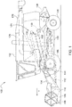
- an agricultural harvester 100 comprises an agricultural combine 102 having a feederhouse 104 extending from the front of the agricultural combine 102, and the chassis 103 supported on at least one wheel 105 for travel through an agricultural field to harvest crops, and an agricultural harvesting head 106 supported on forward end of the feederhouse 104.
- the agricultural harvester 100 travels in a direction of travel "V" through the field to harvest crop.
- Crop plants are severed by reciprocating knife 108 that extends across the width of the agricultural harvesting head 106.
- the cut crop material falls backward on to a conveyor 110.
- the conveyor 110 carries cut crop material to the middle of the agricultural combine 102 and transmits it into a forward opening of the feederhouse 104.
- a conveyor 112 inside the feederhouse 104 carries the cut crop material rearward and upward, through a rear opening in the feederhouse and into a rotary cylinder conveyor 114.
- the rotary cylinder conveyor 114 throws the cut crop material into a threshing, separating, and cleaning mechanism 124, which then threshes the cut crop material, separates the cut crop material into grain and material other than grain (MOG), and cleans the grain.
- the rotary cylinder conveyor 114 is driven in rotation about a laterally extending and generally horizontal rotational axis.
- the clean grain is carried upward into a grain reservoir 126 where it is stored for later unloading through and unloading conveyor 128.
- the threshing, separating, and cleaning mechanism 124 includes an elongate cylinder 130 oriented in a longitudinal direction (i.e. generally parallel to the direction of travel "V" of the agricultural harvester 100).
- the lower portion of the cylinder 130 is disposed within a semicircular concave 132 (also known as a threshing basket) that also extends in a longitudinal direction. Cut crop material is received in a gap between the cylinder 130 and the concave 132 and is carried rearward between the two.
- Grain separated from MOG falls through holes in the concave 132 and into a cleaning shoe 134.
- the MOG is carried rearward in the gap between the cylinder 130 and the concave 132 until it is released at the rear of the cylinder and concave.
- MOG released at the rear of the cylinder in concave is received in a second rotary cylinder conveyor 136.
- the second conveyor 136 throws the MOG rearward where it is deposited upon the ground and/or passes through a chopper 138, which chops the MOG and distributes the chopped MOG over the ground.
- the second conveyor 136 is driven in rotation around a laterally extending and generally horizontal rotational axis.
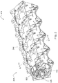
- Cylinder 200 is shown in Figure 2 and in exploded view in Figure 3 .
- the cylinder 200 is typical of both the rotary cylinder conveyors described above.
- the cylinder 200 includes an elongate central shaft 202 on which a cylindrical drum having a cylindrical surface 204 is mounted.
- the cylindrical drum is comprised of a plurality of individual cylinder segments 206 that extend the length of the cylinder 200.
- the cylinder segments 206 collectively define the cylindrical surface 204 of the cylindrical drum.
- Each cylinder segment 206 extends partway around the circumference of the elongate central shaft 202, enclosing an arc of 60°. When assembled as shown in Figure 2 , each cylinder segment 206 abuts or slightly overlaps its adjacent cylinder segment 206 to create a continuous, generally cylindrical outer surface. In the embodiment illustrated in Figure 2 , five of these cylinder segments 206 are required to provide a continuous cylindrical surface 204 of 360° that extends about and is concentric with the central shaft 202.
- each of the radial supports 300 has a central hole 302 that is sized to receive the elongate central shaft 202.
- a small sliding clearance between the central shaft 202 and the central hole 302 is provided to permit the radial supports 300 to be assembled on the elongate central shaft 202 by inserting each support onto a free end of the central shaft and sliding them into position.
- Each support 300 is generally flat, planar, and circular having a circular central hole 302 that is concentric with the outer edge of the support 300.
- the outer surface 306 of each support 300 is generally cylindrical and is formed as a narrow ring.
- Mounts 304 (here shown as threaded holes) are formed in the outwardly facing surface of the outer surface 306 and are distributed evenly around the circumference of the outer surface 306.
- the radial supports are first mounted on the elongate central shaft 202 in a spaced-apart relation.
- the cylindrical surface 204 is then assembled by fastening each of the six cylinder segments 206 to the outer surfaces 306 of the supports.
- Fasteners 308 (here shown as bolts) extend through corresponding holes 310 in each of the cylinder segments 206, and are fixed to mounts 304. In this manner, fasteners 308 secure each of the cylinder segments 206 to the outer edge 308 of each of the supports 300.
- the shaft 202 and the supports 300 are relatively small, and thus leave a large empty space. Dirt, MOG, chaff, seed, and other unwanted material can easily pass through gaps between the cylinder segments 206 and apertures 312 in each of the supports 300. This material accumulates on the bottom inside surfaces 314 of the individual cylinder segments 206, adheres to these surfaces when the harvester 100 is stopped, and causes unbalanced rotation when the harvester 100 and the cylinder 200 started up.
- fillers 400 are provided that fill the large empty space on the inside of the cylinder. These fillers 400 are illustrated in Figures 4-6 .
- the function of the fillers is to fill a void that would otherwise be at least partially filled by unwanted matter and cause unbalanced rotation of the rotary cylinder conveyor 114.
- each filler 400 has an outwardly facing convex surface 402 that closely approximates the inner cylindrical surface collectively defined by the cylinder segments 206 (see Fig. 6 ). For that reason also, each filler 400 has a concave surface 404 that is cylindrical and closely approximates the outer cylindrical surface 406 of the elongate central shaft 202 (see Fig. 6 ). In the arrangement shown in Figure 6 , the convex surface and the concave surface are concentric about a longitudinal rotational axis of central shaft 202.
- Each filler 400 has two axial ends: a first end 408 that is planar and closely approximates an axial side surface of a first support 300, and a second end 410 that is planar and closely approximates an axial side surface of an adjacent, second support 300.
- Each filler 400 is preferably lightweight, since it functions to displace loose matter.
- the body of the filler is preferably made of plastic, preferably a thermoplastic. It is preferably hollow. It is preferably formed by a blow-molding or rotational molding. These manufacturing processes provide a high overall volume for the part (and thus high displacement of loose matter), yet still be lightweight, inexpensive, and have a thin wall structure. These processes also permit the filler 400 to be engineered with a relatively complex outer surface contour to more effectively and closely follow the abutting/adjacent inner surface contours of the cylinder 200 and the central shaft 202, thereby filling a greater volume and more effectively displacing MOG, dirt, and other light matter at low cost.
- the filler Since the sole or primary function of the filler is merely to fill a void and thereby exclude loose contaminants from entering and accumulating in the cylindrical conveyor, it does not need to be a structural member or provide structural strength to other components.
- a filler in the form of a lightweight hollow plastic body is particularly suited to this application.
- the filler 400 can be in the form of a cylindrical outer wall having outer surface that closely accommodates or abuts the inner surface of the cylinder 200, and a cylindrical concentric hole sized to closely accommodate or abut the shaft 202, and two opposing end walls that are generally perpendicular to the cylindrical concentric hole and that closely accommodate or abut the facing side surfaces of two adjacent radial supports 300.
- substantially the entire empty space between two adjacent radial supports 300 extending from the outer surface of shaft 202 and the inner surface of the individual cylinder segments 206 could be almost entirely filled with the filler 400, thus substantially displacing any otherwise empty space between two adjacent radial supports 300.
- This arrangement would be assembled by sliding a radial support 300 onto the shaft, then a filler 400, then a second radial support 300, then a filler 400, etc., until all the radial supports 300 and the fillers 400 were on the shaft. At this point, each of the five individual cylinder segments 206 would be fixed to the radial supports to create the cylinder 200.
- each filler 400 is in the form of two individually formed half cylinders that are sized to be inserted into an existing cylinder 200 on a combine.
- one or more of the individual cylinder segments 206 is unbolted from the cylinder 200 already mounted on a combine to thereby create a side opening in the cylinder 200.
- a first half cylinder and then a second half cylinder of the filler 400 are then sequentially inserted through this side opening and maneuvered around the central shaft 202 until they are in the relative position shown in Figure 6 .
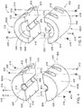
- the filler 400 (shown in Figure 4 ) is formed of two abutting half cylinders 400A, 400B that together define a cylindrical filler 400.
- the filler 400 (shown in Figure 5 ) is formed of two abutting half cylinders 400C, 400D.
- Each of the half cylinders 400A, 400B are identical. They are made in the same mold. Each of them has two flat end walls 408 that are perpendicular to a longitudinal axis 412. Each half cylinder 400A, 400B is semi cylindrical, extending 180° around longitudinal axis 412. Each half cylinder 400A, 400B has two surfaces 414 that are coplanar. Longitudinal axis 412 lies in the plane defined by the surfaces 414.
- Half cylinders 400A, 400B can be rotated into a position (shown in Figure 4 ) in which surfaces 414 of half cylinder 400A are parallel to and abut corresponding surfaces 414 of half cylinder 400B. In this position, and surfaces 408 of half cylinders 400A, 400B are coplanar.
- Fasteners 418 may be permanent fasteners, such as rivets, or they may be (as shown herein) removable and replaceable, such as threaded fasteners, including screws, nuts, bolts, or the like.
- Figure 5 shows a third alternative arrangement identical to the arrangement of Figure 4 in both construction, operation and use with one difference: a semi-cylindrical recess 500 is provided in one of the end surfaces 408 of each of the half cylinders 400C, 400D. Together these half cylindrical recesses 500 define a cylindrical recess.
- the cylindrical recess is provided to surround and accommodate a clamp 502 ( Figure 3 ).
- Clamp 502 surrounds central shaft 202 and fixes a radial support 300 disposed at the end of the cylinder 200 to the central shaft 202.
- Figure 6 shows the relative orientation and spacing of the filler 400 with respect to the central shaft 202 and the inner cylindrical surface of the drum.
- the spacing between the filler 400 and the inner surface of the drum is small. The surfaces may abut or they may not.
- the gaps between the filler 400, the central shaft 202 and the inner cylindrical surface of the drum are preferably large enough to permit the cylinder 200 to be readily assembled. At the same time, they cannot be so large that enough dirt, MOG, seed, and other contaminants can accumulate in the gap during operation and cause damaging rotational imbalance of the cylinder 200.
Landscapes
- Engineering & Computer Science (AREA)
- Mechanical Engineering (AREA)
- Life Sciences & Earth Sciences (AREA)
- Environmental Sciences (AREA)
- Combined Means For Separation Of Solids (AREA)
- Harvester Elements (AREA)
Abstract
Description
- This invention relates generally to agricultural harvesters. More particularly it relates to rotary crop conveyors such as drum conveyors. Even more particularly it relates to beaters and feed accelerators.
- Agricultural harvesters, such as agricultural combines, are designed to travel through agricultural fields harvesting crops. Agricultural combines receive crop severed from the ground and convey it to threshing, separating and cleaning devices within the agricultural combine.
- In order to convey the cut crop material through the combine a variety of conveyors are used. In one typical arrangement, the conveyors comprise a rotating cylinder with protrusions extending from its outermost surface to engage the cut crop material and move it rearward.
- These cylinders may be driven at high speed (e.g. 200-1200 RPM) in order to throw the cut crop material further.
- Unless these cylinders are well-balanced, the high speed of rotation can cause them to oscillate, shaking the combine, and damaging components.
- One significant source of imbalance is the accumulation of dirt, chaff, straw, and crop within the hollow interior of the cylinder. This material filters into the cylinder through open ends of the cylinder, through access holes, or gaps between multiple sections of the cylinder. The accumulation will dry, become hardened, and adhere to the inner surface of the cylinder.
- One way to reduce this accumulation of material is to fill the cylindrical voids with rubber, expanded foam, or other materials. Unfortunately, this material significantly increases the weight of the cylinders. Further, since it is "glued" to the inner surfaces of the cylinder and the driveshaft upon which the cylinder is mounted, the rotating cylinder conveyors cannot be easily disassembled.
- What is needed is a filler for a cylindrical conveyor that can be easily inserted and removed for maintenance purposes, is lightweight and effectively fills a void inside the cylindrical conveyor to exclude contaminants that would otherwise form within the cylindrical conveyor, imbalance the conveyor, and make the cylindrical conveyor difficult to clean.
- It is an object of this invention to provide such an arrangement.
- In accordance with a first aspect of the invention a plastic filler is provided for a cylindrical conveyor, wherein the cylindrical conveyor comprises an elongate central shaft, a plurality of radial supports supported on the shaft in a spaced apart relation along the shaft, and a drum supported on the supports in positions that are coaxial with the central shaft, wherein the plastic filler has an outer surface that is generally cylindrical and immediately adjacent to an inner surface of the drum, an inner surface adjacent to and surrounding the central shaft, a first end adjacent to a first one of the plurality of radial supports, and a second end adjacent to a second one of the plurality of radial supports whereby the plastic filler thereby fills a void and excludes contaminants from between the central shaft and the drum.
- The plastic filler may include a hollow thermoplastic body having a cylindrical outer surface.
- The plastic filler may include two or more hollow thermoplastic bodies in an abutting relationship that together define a cylindrical outer surface.
- The plastic filler made to find a generally cylindrical outer surface that is closely spaced to an inner surface of the drum over substantially an entire length of the plastic filler, and a cylindrical inner surface that extends around and is closely spaced to the central shaft over substantially an entire length of the central shaft.
- The plastic filler may include two hollow bodies that are fixed to each other with at least one fastener.
- The drum may include one or more individual cylinder segments that are removable from the cylindrical conveyor to thereby provide an opening in the drum, and the plastic filler may be sized for insertion into cylindrical conveyor through the opening in the drum.
- The plastic filler may include two hollow bodies that can be inserted individually and sequentially into the cylindrical conveyor through the opening.
- The two hollow bodies maybe fixed to each other with fasteners once they are inserted into the drum.
- In accordance with a second aspect of the invention, a cylindrical conveyor may include an elongate central shaft, a plurality of radial supports supported on the shaft in a spaced apart relation along the longitudinal length of the shaft, a drum supported on the supports in a position that are coaxial with the central shaft, and a plastic filler as described herein.
- In accordance with a third aspect of the invention, an agricultural combine may include a chassis supported on at least one wheel, a feederhouse supported on the chassis, and configured to convey cut crop material from an agricultural harvesting head to a threshing, separating, and cleaning mechanism, and at least one cylindrical conveyor supported on the chassis as described herein.
-
- Fig: 1
- illustrates an agricultural harvester in side view in accordance with the present invention.
- Fig: 2
- is a perspective view of a rotary conveyor cylinder of the agricultural harvester of
Figure 1 in accordance with the present invention. - Fig. 3
- is an exploded perspective view of the rotary conveyor cylinders of
Figures 1-2 . - Fig. 4
- is an exploded view of a first conveyor drum filler for the rotary conveyor cylinders of
Figures 1-2 . - Fig. 5
- is an exploded view views of a second conveyor drum filler for the rotary conveyor cylinders of
Figures 1-2 . - Fig. 6
- is a cross-sectional view of a conveyor drum (with fillers) taken at section line 6-6 in
Figure 2 . - In
Figure 1 , anagricultural harvester 100 comprises anagricultural combine 102 having afeederhouse 104 extending from the front of theagricultural combine 102, and thechassis 103 supported on at least onewheel 105 for travel through an agricultural field to harvest crops, and anagricultural harvesting head 106 supported on forward end of thefeederhouse 104. Theagricultural harvester 100 travels in a direction of travel "V" through the field to harvest crop. - Crop plants are severed by reciprocating
knife 108 that extends across the width of theagricultural harvesting head 106. The cut crop material falls backward on to aconveyor 110. - The
conveyor 110 carries cut crop material to the middle of theagricultural combine 102 and transmits it into a forward opening of thefeederhouse 104. - A
conveyor 112 inside thefeederhouse 104 carries the cut crop material rearward and upward, through a rear opening in the feederhouse and into arotary cylinder conveyor 114. - The
rotary cylinder conveyor 114 throws the cut crop material into a threshing, separating, andcleaning mechanism 124, which then threshes the cut crop material, separates the cut crop material into grain and material other than grain (MOG), and cleans the grain. Therotary cylinder conveyor 114 is driven in rotation about a laterally extending and generally horizontal rotational axis. - The clean grain is carried upward into a
grain reservoir 126 where it is stored for later unloading through and unloadingconveyor 128. - The threshing, separating, and
cleaning mechanism 124 includes anelongate cylinder 130 oriented in a longitudinal direction (i.e. generally parallel to the direction of travel "V" of the agricultural harvester 100). The lower portion of thecylinder 130 is disposed within a semicircular concave 132 (also known as a threshing basket) that also extends in a longitudinal direction. Cut crop material is received in a gap between thecylinder 130 and the concave 132 and is carried rearward between the two. - Grain separated from MOG falls through holes in the concave 132 and into a
cleaning shoe 134. The MOG is carried rearward in the gap between thecylinder 130 and the concave 132 until it is released at the rear of the cylinder and concave. - MOG released at the rear of the cylinder in concave is received in a second
rotary cylinder conveyor 136. Thesecond conveyor 136 throws the MOG rearward where it is deposited upon the ground and/or passes through achopper 138, which chops the MOG and distributes the chopped MOG over the ground. Thesecond conveyor 136 is driven in rotation around a laterally extending and generally horizontal rotational axis. -
Cylinder 200 is shown inFigure 2 and in exploded view inFigure 3 . Thecylinder 200 is typical of both the rotary cylinder conveyors described above. - The
cylinder 200 includes an elongatecentral shaft 202 on which a cylindrical drum having acylindrical surface 204 is mounted. The cylindrical drum is comprised of a plurality ofindividual cylinder segments 206 that extend the length of thecylinder 200. Thecylinder segments 206 collectively define thecylindrical surface 204 of the cylindrical drum. - There are six
cylinder segments 206. Eachcylinder segment 206 extends partway around the circumference of the elongatecentral shaft 202, enclosing an arc of 60°. When assembled as shown inFigure 2 , eachcylinder segment 206 abuts or slightly overlaps itsadjacent cylinder segment 206 to create a continuous, generally cylindrical outer surface. In the embodiment illustrated inFigure 2 , five of thesecylinder segments 206 are required to provide a continuouscylindrical surface 204 of 360° that extends about and is concentric with thecentral shaft 202. - As best shown in
Figure 3 , fiveradial supports 300 are disposed on the elongatecentral shaft 202. Each of the radial supports 300 has acentral hole 302 that is sized to receive the elongatecentral shaft 202. A small sliding clearance between thecentral shaft 202 and thecentral hole 302 is provided to permit the radial supports 300 to be assembled on the elongatecentral shaft 202 by inserting each support onto a free end of the central shaft and sliding them into position. - Each
support 300 is generally flat, planar, and circular having a circularcentral hole 302 that is concentric with the outer edge of thesupport 300. Theouter surface 306 of eachsupport 300 is generally cylindrical and is formed as a narrow ring. Mounts 304 (here shown as threaded holes) are formed in the outwardly facing surface of theouter surface 306 and are distributed evenly around the circumference of theouter surface 306. - To assemble the
cylinder 200, the radial supports are first mounted on the elongatecentral shaft 202 in a spaced-apart relation. Thecylindrical surface 204 is then assembled by fastening each of the sixcylinder segments 206 to theouter surfaces 306 of the supports. Fasteners 308 (here shown as bolts) extend throughcorresponding holes 310 in each of thecylinder segments 206, and are fixed tomounts 304. In this manner,fasteners 308 secure each of thecylinder segments 206 to theouter edge 308 of each of thesupports 300. - A large empty space exists on the inside of the cylinder formed from the
cylinder segments 206. Theshaft 202 and thesupports 300 are relatively small, and thus leave a large empty space. Dirt, MOG, chaff, seed, and other unwanted material can easily pass through gaps between thecylinder segments 206 andapertures 312 in each of thesupports 300. This material accumulates on the bottom insidesurfaces 314 of theindividual cylinder segments 206, adheres to these surfaces when theharvester 100 is stopped, and causes unbalanced rotation when theharvester 100 and thecylinder 200 started up. - To prevent this unbalanced rotation,
fillers 400 are provided that fill the large empty space on the inside of the cylinder. Thesefillers 400 are illustrated inFigures 4-6 . - The function of the fillers is to fill a void that would otherwise be at least partially filled by unwanted matter and cause unbalanced rotation of the
rotary cylinder conveyor 114. The more that void is filled, the less space there is for unwanted material. - For that reason, each
filler 400 has an outwardly facingconvex surface 402 that closely approximates the inner cylindrical surface collectively defined by the cylinder segments 206 (seeFig. 6 ). For that reason also, eachfiller 400 has aconcave surface 404 that is cylindrical and closely approximates the outer cylindrical surface 406 of the elongate central shaft 202 (seeFig. 6 ). In the arrangement shown inFigure 6 , the convex surface and the concave surface are concentric about a longitudinal rotational axis ofcentral shaft 202. - Each
filler 400 has two axial ends: afirst end 408 that is planar and closely approximates an axial side surface of afirst support 300, and asecond end 410 that is planar and closely approximates an axial side surface of an adjacent,second support 300. - Each
filler 400 is preferably lightweight, since it functions to displace loose matter. For that reason the body of the filler is preferably made of plastic, preferably a thermoplastic. It is preferably hollow. It is preferably formed by a blow-molding or rotational molding. These manufacturing processes provide a high overall volume for the part (and thus high displacement of loose matter), yet still be lightweight, inexpensive, and have a thin wall structure. These processes also permit thefiller 400 to be engineered with a relatively complex outer surface contour to more effectively and closely follow the abutting/adjacent inner surface contours of thecylinder 200 and thecentral shaft 202, thereby filling a greater volume and more effectively displacing MOG, dirt, and other light matter at low cost. - Since the sole or primary function of the filler is merely to fill a void and thereby exclude loose contaminants from entering and accumulating in the cylindrical conveyor, it does not need to be a structural member or provide structural strength to other components. A filler in the form of a lightweight hollow plastic body is particularly suited to this application.
- In one arrangement (not shown), the
filler 400 can be in the form of a cylindrical outer wall having outer surface that closely accommodates or abuts the inner surface of thecylinder 200, and a cylindrical concentric hole sized to closely accommodate or abut theshaft 202, and two opposing end walls that are generally perpendicular to the cylindrical concentric hole and that closely accommodate or abut the facing side surfaces of two adjacent radial supports 300. - In this arrangement, substantially the entire empty space between two adjacent radial supports 300 extending from the outer surface of
shaft 202 and the inner surface of theindividual cylinder segments 206 could be almost entirely filled with thefiller 400, thus substantially displacing any otherwise empty space between two adjacent radial supports 300. - This arrangement would be assembled by sliding a
radial support 300 onto the shaft, then afiller 400, then a secondradial support 300, then afiller 400, etc., until all the radial supports 300 and thefillers 400 were on the shaft. At this point, each of the fiveindividual cylinder segments 206 would be fixed to the radial supports to create thecylinder 200. - There are drawbacks to this configuration, particularly when an existing
cylinder 200 inside to combine is to be retrofitted withfillers 400. To retrofit an existingcylinder 200 withfillers 400 configured in this manner would be impossible without removing theentire cylinder 200 from the combine, removing all theindividual cylinder segments 206, and then sliding all of the radial supports 300 off theshaft 202, then reassembling theentire cylinder 200. For that reason, another arrangement of thefillers 400 is provided that can be easily retrofitted into acylinder 200 already installed in the combine. - In this alternative arrangement, each
filler 400 is in the form of two individually formed half cylinders that are sized to be inserted into an existingcylinder 200 on a combine. To do this retrofit, one or more of theindividual cylinder segments 206 is unbolted from thecylinder 200 already mounted on a combine to thereby create a side opening in thecylinder 200. - A first half cylinder and then a second half cylinder of the
filler 400 are then sequentially inserted through this side opening and maneuvered around thecentral shaft 202 until they are in the relative position shown inFigure 6 . In one configuration of this alternative arrangement, the filler 400 (shown inFigure 4 ) is formed of two abuttinghalf cylinders cylindrical filler 400. In another configuration, the filler 400 (shown inFigure 5 ) is formed of two abuttinghalf cylinders - Each of the
half cylinders flat end walls 408 that are perpendicular to alongitudinal axis 412. Eachhalf cylinder longitudinal axis 412. Eachhalf cylinder surfaces 414 that are coplanar.Longitudinal axis 412 lies in the plane defined by thesurfaces 414.Half cylinders Figure 4 ) in which surfaces 414 ofhalf cylinder 400A are parallel to andabut corresponding surfaces 414 ofhalf cylinder 400B. In this position, and surfaces 408 ofhalf cylinders - Four
apertures 416 are provided on opposite sides ofhalf cylinders apertures 416 inhalf cylinder 400A are aligned withapertures 416 andhalf cylinder 400B to permitfasteners 418 to extend through the alignedapertures 416 and secure the twohalf cylinders Fasteners 418 may be permanent fasteners, such as rivets, or they may be (as shown herein) removable and replaceable, such as threaded fasteners, including screws, nuts, bolts, or the like. -
Figure 5 shows a third alternative arrangement identical to the arrangement ofFigure 4 in both construction, operation and use with one difference: asemi-cylindrical recess 500 is provided in one of the end surfaces 408 of each of thehalf cylinders cylindrical recesses 500 define a cylindrical recess. The cylindrical recess is provided to surround and accommodate a clamp 502 (Figure 3 ). Clamp 502 surroundscentral shaft 202 and fixes aradial support 300 disposed at the end of thecylinder 200 to thecentral shaft 202. -
Figure 6 shows the relative orientation and spacing of thefiller 400 with respect to thecentral shaft 202 and the inner cylindrical surface of the drum. The spacing between thefiller 400 and the inner surface of the drum is small. The surfaces may abut or they may not. - The gaps between the
filler 400, thecentral shaft 202 and the inner cylindrical surface of the drum are preferably large enough to permit thecylinder 200 to be readily assembled. At the same time, they cannot be so large that enough dirt, MOG, seed, and other contaminants can accumulate in the gap during operation and cause damaging rotational imbalance of thecylinder 200. - The embodiments disclosed in this application explain at least one arrangement of the invention in sufficient detail to permit someone skilled in the art to make at least one embodiment of the invention. Other arrangements and embodiments are possible, even expected. The invention itself is defined by the claims.
Claims (10)
- A plastic filler for a cylindrical conveyor, wherein the cylindrical conveyor comprises an elongate central shaft, a plurality of radial supports supported on the shaft in a spaced apart relation along the shaft, and a drum supported on the supports in positions that are coaxial with the central shaft, wherein the plastic filler has an outer surface that is generally cylindrical and immediately adjacent to an inner surface of the drum, an inner surface adjacent to and surrounding the central shaft, a first end adjacent to a first one of the plurality of radial supports, and a second end adjacent to a second one of the plurality of radial supports whereby the plastic filler thereby fills a void and excludes contaminants from between the central shaft and the drum.
- The plastic filler of Claim 1, wherein the plastic filler comprises a hollow thermoplastic body having a cylindrical outer surface.
- The plastic filler of Claim 2, wherein the plastic filler comprises two or more hollow thermoplastic bodies in an abutting relationship that together define a cylindrical outer surface.
- The plastic filler of Claim 1, wherein the plastic filler defines a generally cylindrical outer surface that is closely spaced to an inner surface of the drum over substantially an entire length of the plastic filler, and a cylindrical inner surface that extends around and is closely spaced to the central shaft over substantially an entire length of the central shaft.
- The plastic filler of Claim 1, wherein the plastic filler comprises two hollow bodies that are fixed to each other with at least one fastener.
- The plastic filler of Claim 1, wherein the drum comprises one or more individual cylinder segments that are removable from the cylindrical conveyor to thereby provide an opening in the drum, and further wherein the plastic filler is sized for insertion into cylindrical conveyor through the opening in the drum.
- The plastic filler of Claim 6, wherein the plastic filler comprises two hollow bodies that can be inserted individually and sequentially into the cylindrical conveyor through the opening.
- The plastic filler of Claim 7, where the two hollow bodies can be fixed to each other with fasteners once they are inserted into the drum.
- A cylindrical conveyor comprising an elongate central shaft, a plurality of radial supports supported on the shaft in a spaced apart relation along the longitudinal length of the shaft, a drum supported on the supports in a position that are coaxial with the central shaft, and a plastic filler in accordance with Claim 1.
- An agricultural combine comprising a chassis supported on at least one wheel, a feederhouse supported on the chassis, and configured to convey cut crop material from an agricultural harvesting head to a threshing, separating, and cleaning mechanism, and at least one cylindrical conveyor supported on the chassis in accordance with Claim 9.
Applications Claiming Priority (1)
| Application Number | Priority Date | Filing Date | Title |
|---|---|---|---|
| US15/675,267 US10485179B2 (en) | 2017-08-11 | 2017-08-11 | Conveyor drum filler for debris exclusion |
Publications (2)
| Publication Number | Publication Date |
|---|---|
| EP3440923A1 true EP3440923A1 (en) | 2019-02-13 |
| EP3440923B1 EP3440923B1 (en) | 2021-01-13 |
Family
ID=63143057
Family Applications (1)
| Application Number | Title | Priority Date | Filing Date |
|---|---|---|---|
| EP18187033.8A Active EP3440923B1 (en) | 2017-08-11 | 2018-08-02 | Conveyor drum filler for debris exclusion |
Country Status (2)
| Country | Link |
|---|---|
| US (1) | US10485179B2 (en) |
| EP (1) | EP3440923B1 (en) |
Citations (4)
| Publication number | Priority date | Publication date | Assignee | Title |
|---|---|---|---|---|
| US4003191A (en) * | 1976-03-29 | 1977-01-18 | Sperry Rand Corporation | Barrier means in a combine harvesting header |
| US5980383A (en) * | 1997-10-21 | 1999-11-09 | Medley; William A. | Attachment for an auger of a harvesting machine |
| CN1861500A (en) * | 2006-05-29 | 2006-11-15 | 贵州创意达科技股份有限公司 | Super high molecular weight polyethylene full plastic support roller |
| CN106915593A (en) * | 2017-02-21 | 2017-07-04 | 嘉善优耐斯环保科技有限公司 | Carrying roller |
Family Cites Families (8)
| Publication number | Priority date | Publication date | Assignee | Title |
|---|---|---|---|---|
| US2263439A (en) * | 1941-05-23 | 1941-11-18 | Andrews And Goodrich Inc | Roll for driers and the like |
| AT346004B (en) * | 1976-12-10 | 1978-10-25 | Voest Ag | STRAND GUIDE ROLLER FOR A CONTINUOUS CASTING PLANT |
| DE7731162U1 (en) | 1977-10-08 | 1978-01-26 | Gebr. Claas Maschinenfabrik Gmbh, 4834 Harsewinkel | HARVESTER |
| US4402390A (en) * | 1981-06-12 | 1983-09-06 | Stilson Division Of Stocker & Yale, Inc. | Conveyor roll |
| US4969548A (en) * | 1988-04-27 | 1990-11-13 | Kornylak Corporation | Compression set limiting gravity conveyor |
| US7213701B2 (en) * | 2005-02-03 | 2007-05-08 | Tgw Ermanco Incorporated | Conveyor roller axle stiffener |
| AU2011359187B2 (en) | 2011-02-17 | 2015-06-18 | Cnh Industrial Belgium N.V. | A method of preventing debris accumulation within voids of crop engaging components of an agricultural combine. |
| US8672116B2 (en) * | 2011-09-23 | 2014-03-18 | Bastian Automation Engineering, Llc | Sprung pin conveyor roller bearing |
-
2017
- 2017-08-11 US US15/675,267 patent/US10485179B2/en active Active
-
2018
- 2018-08-02 EP EP18187033.8A patent/EP3440923B1/en active Active
Patent Citations (4)
| Publication number | Priority date | Publication date | Assignee | Title |
|---|---|---|---|---|
| US4003191A (en) * | 1976-03-29 | 1977-01-18 | Sperry Rand Corporation | Barrier means in a combine harvesting header |
| US5980383A (en) * | 1997-10-21 | 1999-11-09 | Medley; William A. | Attachment for an auger of a harvesting machine |
| CN1861500A (en) * | 2006-05-29 | 2006-11-15 | 贵州创意达科技股份有限公司 | Super high molecular weight polyethylene full plastic support roller |
| CN106915593A (en) * | 2017-02-21 | 2017-07-04 | 嘉善优耐斯环保科技有限公司 | Carrying roller |
Also Published As
| Publication number | Publication date |
|---|---|
| US20190223382A1 (en) | 2019-07-25 |
| US10485179B2 (en) | 2019-11-26 |
| EP3440923B1 (en) | 2021-01-13 |
| BR102018016390A2 (en) | 2019-04-16 |
Similar Documents
| Publication | Publication Date | Title |
|---|---|---|
| US20050026663A1 (en) | Frusto-conical drum infeed and threshing region for a combine rotor | |
| US11272665B2 (en) | Tined-tube auger | |
| EP3381266A1 (en) | Cogged feederhouse front drum | |
| US6551186B2 (en) | Beater for a combine harvester | |
| JP7547517B2 (en) | combine | |
| BR102018003704A2 (en) | toothed drive arrangement | |
| EP3381267A1 (en) | Slat insert for noise/wear attenuation in a feederhouse conveyor | |
| US7669396B2 (en) | Timing crank and cylindrical conveyor for an agricultural harvester | |
| EP3440923B1 (en) | Conveyor drum filler for debris exclusion | |
| EP3311647B1 (en) | Finger assembly for a feed drum conveyor of an agricultural harvesting head | |
| US12557733B2 (en) | System for supporting an unload tube of an agricultural vehicle | |
| BR102018016390B1 (en) | CYLINDRICAL CONVEYOR, AND, AGRICULTURAL COMBINED | |
| WO2022019073A1 (en) | Threshing device and harvesting machine | |
| US12317780B2 (en) | Brush system for a threshing and separating system of an agricultural harvester | |
| JP6840042B2 (en) | Threshing device | |
| JPS6443Y2 (en) | ||
| JP2022021783A (en) | Thresher and harvester | |
| KR102275501B1 (en) | Teeth of threshing device and Combine with the same, Teeth assembling methods of combine threshing device | |
| JP6840043B2 (en) | Threshing device | |
| JP6941984B2 (en) | combine | |
| JP2022021781A (en) | Thresher | |
| CA2525903C (en) | Replaceable feed segment for the beater of a combine harvester | |
| JP2022021784A (en) | Threshing device |
Legal Events
| Date | Code | Title | Description |
|---|---|---|---|
| PUAI | Public reference made under article 153(3) epc to a published international application that has entered the european phase |
Free format text: ORIGINAL CODE: 0009012 |
|
| STAA | Information on the status of an ep patent application or granted ep patent |
Free format text: STATUS: THE APPLICATION HAS BEEN PUBLISHED |
|
| AK | Designated contracting states |
Kind code of ref document: A1 Designated state(s): AL AT BE BG CH CY CZ DE DK EE ES FI FR GB GR HR HU IE IS IT LI LT LU LV MC MK MT NL NO PL PT RO RS SE SI SK SM TR |
|
| AX | Request for extension of the european patent |
Extension state: BA ME |
|
| STAA | Information on the status of an ep patent application or granted ep patent |
Free format text: STATUS: REQUEST FOR EXAMINATION WAS MADE |
|
| 17P | Request for examination filed |
Effective date: 20190814 |
|
| RBV | Designated contracting states (corrected) |
Designated state(s): AL AT BE BG CH CY CZ DE DK EE ES FI FR GB GR HR HU IE IS IT LI LT LU LV MC MK MT NL NO PL PT RO RS SE SI SK SM TR |
|
| GRAP | Despatch of communication of intention to grant a patent |
Free format text: ORIGINAL CODE: EPIDOSNIGR1 |
|
| STAA | Information on the status of an ep patent application or granted ep patent |
Free format text: STATUS: GRANT OF PATENT IS INTENDED |
|
| INTG | Intention to grant announced |
Effective date: 20200909 |
|
| GRAS | Grant fee paid |
Free format text: ORIGINAL CODE: EPIDOSNIGR3 |
|
| GRAA | (expected) grant |
Free format text: ORIGINAL CODE: 0009210 |
|
| STAA | Information on the status of an ep patent application or granted ep patent |
Free format text: STATUS: THE PATENT HAS BEEN GRANTED |
|
| AK | Designated contracting states |
Kind code of ref document: B1 Designated state(s): AL AT BE BG CH CY CZ DE DK EE ES FI FR GB GR HR HU IE IS IT LI LT LU LV MC MK MT NL NO PL PT RO RS SE SI SK SM TR |
|
| REG | Reference to a national code |
Ref country code: GB Ref legal event code: FG4D |
|
| REG | Reference to a national code |
Ref country code: CH Ref legal event code: EP |
|
| REG | Reference to a national code |
Ref country code: IE Ref legal event code: FG4D |
|
| REG | Reference to a national code |
Ref country code: DE Ref legal event code: R096 Ref document number: 602018011764 Country of ref document: DE |
|
| REG | Reference to a national code |
Ref country code: AT Ref legal event code: REF Ref document number: 1353843 Country of ref document: AT Kind code of ref document: T Effective date: 20210215 |
|
| REG | Reference to a national code |
Ref country code: AT Ref legal event code: MK05 Ref document number: 1353843 Country of ref document: AT Kind code of ref document: T Effective date: 20210113 |
|
| REG | Reference to a national code |
Ref country code: NL Ref legal event code: MP Effective date: 20210113 |
|
| REG | Reference to a national code |
Ref country code: LT Ref legal event code: MG9D |
|
| PG25 | Lapsed in a contracting state [announced via postgrant information from national office to epo] |
Ref country code: LT Free format text: LAPSE BECAUSE OF FAILURE TO SUBMIT A TRANSLATION OF THE DESCRIPTION OR TO PAY THE FEE WITHIN THE PRESCRIBED TIME-LIMIT Effective date: 20210113 Ref country code: NO Free format text: LAPSE BECAUSE OF FAILURE TO SUBMIT A TRANSLATION OF THE DESCRIPTION OR TO PAY THE FEE WITHIN THE PRESCRIBED TIME-LIMIT Effective date: 20210413 Ref country code: PT Free format text: LAPSE BECAUSE OF FAILURE TO SUBMIT A TRANSLATION OF THE DESCRIPTION OR TO PAY THE FEE WITHIN THE PRESCRIBED TIME-LIMIT Effective date: 20210513 Ref country code: BG Free format text: LAPSE BECAUSE OF FAILURE TO SUBMIT A TRANSLATION OF THE DESCRIPTION OR TO PAY THE FEE WITHIN THE PRESCRIBED TIME-LIMIT Effective date: 20210413 Ref country code: FI Free format text: LAPSE BECAUSE OF FAILURE TO SUBMIT A TRANSLATION OF THE DESCRIPTION OR TO PAY THE FEE WITHIN THE PRESCRIBED TIME-LIMIT Effective date: 20210113 Ref country code: GR Free format text: LAPSE BECAUSE OF FAILURE TO SUBMIT A TRANSLATION OF THE DESCRIPTION OR TO PAY THE FEE WITHIN THE PRESCRIBED TIME-LIMIT Effective date: 20210414 Ref country code: HR Free format text: LAPSE BECAUSE OF FAILURE TO SUBMIT A TRANSLATION OF THE DESCRIPTION OR TO PAY THE FEE WITHIN THE PRESCRIBED TIME-LIMIT Effective date: 20210113 |
|
| PG25 | Lapsed in a contracting state [announced via postgrant information from national office to epo] |
Ref country code: SE Free format text: LAPSE BECAUSE OF FAILURE TO SUBMIT A TRANSLATION OF THE DESCRIPTION OR TO PAY THE FEE WITHIN THE PRESCRIBED TIME-LIMIT Effective date: 20210113 Ref country code: PL Free format text: LAPSE BECAUSE OF FAILURE TO SUBMIT A TRANSLATION OF THE DESCRIPTION OR TO PAY THE FEE WITHIN THE PRESCRIBED TIME-LIMIT Effective date: 20210113 Ref country code: RS Free format text: LAPSE BECAUSE OF FAILURE TO SUBMIT A TRANSLATION OF THE DESCRIPTION OR TO PAY THE FEE WITHIN THE PRESCRIBED TIME-LIMIT Effective date: 20210113 Ref country code: LV Free format text: LAPSE BECAUSE OF FAILURE TO SUBMIT A TRANSLATION OF THE DESCRIPTION OR TO PAY THE FEE WITHIN THE PRESCRIBED TIME-LIMIT Effective date: 20210113 Ref country code: AT Free format text: LAPSE BECAUSE OF FAILURE TO SUBMIT A TRANSLATION OF THE DESCRIPTION OR TO PAY THE FEE WITHIN THE PRESCRIBED TIME-LIMIT Effective date: 20210113 |
|
| PG25 | Lapsed in a contracting state [announced via postgrant information from national office to epo] |
Ref country code: IS Free format text: LAPSE BECAUSE OF FAILURE TO SUBMIT A TRANSLATION OF THE DESCRIPTION OR TO PAY THE FEE WITHIN THE PRESCRIBED TIME-LIMIT Effective date: 20210513 |
|
| REG | Reference to a national code |
Ref country code: DE Ref legal event code: R097 Ref document number: 602018011764 Country of ref document: DE |
|
| PG25 | Lapsed in a contracting state [announced via postgrant information from national office to epo] |
Ref country code: CZ Free format text: LAPSE BECAUSE OF FAILURE TO SUBMIT A TRANSLATION OF THE DESCRIPTION OR TO PAY THE FEE WITHIN THE PRESCRIBED TIME-LIMIT Effective date: 20210113 Ref country code: EE Free format text: LAPSE BECAUSE OF FAILURE TO SUBMIT A TRANSLATION OF THE DESCRIPTION OR TO PAY THE FEE WITHIN THE PRESCRIBED TIME-LIMIT Effective date: 20210113 Ref country code: SM Free format text: LAPSE BECAUSE OF FAILURE TO SUBMIT A TRANSLATION OF THE DESCRIPTION OR TO PAY THE FEE WITHIN THE PRESCRIBED TIME-LIMIT Effective date: 20210113 |
|
| PLBE | No opposition filed within time limit |
Free format text: ORIGINAL CODE: 0009261 |
|
| STAA | Information on the status of an ep patent application or granted ep patent |
Free format text: STATUS: NO OPPOSITION FILED WITHIN TIME LIMIT |
|
| PG25 | Lapsed in a contracting state [announced via postgrant information from national office to epo] |
Ref country code: RO Free format text: LAPSE BECAUSE OF FAILURE TO SUBMIT A TRANSLATION OF THE DESCRIPTION OR TO PAY THE FEE WITHIN THE PRESCRIBED TIME-LIMIT Effective date: 20210113 Ref country code: SK Free format text: LAPSE BECAUSE OF FAILURE TO SUBMIT A TRANSLATION OF THE DESCRIPTION OR TO PAY THE FEE WITHIN THE PRESCRIBED TIME-LIMIT Effective date: 20210113 Ref country code: DK Free format text: LAPSE BECAUSE OF FAILURE TO SUBMIT A TRANSLATION OF THE DESCRIPTION OR TO PAY THE FEE WITHIN THE PRESCRIBED TIME-LIMIT Effective date: 20210113 |
|
| 26N | No opposition filed |
Effective date: 20211014 |
|
| PG25 | Lapsed in a contracting state [announced via postgrant information from national office to epo] |
Ref country code: AL Free format text: LAPSE BECAUSE OF FAILURE TO SUBMIT A TRANSLATION OF THE DESCRIPTION OR TO PAY THE FEE WITHIN THE PRESCRIBED TIME-LIMIT Effective date: 20210113 Ref country code: ES Free format text: LAPSE BECAUSE OF FAILURE TO SUBMIT A TRANSLATION OF THE DESCRIPTION OR TO PAY THE FEE WITHIN THE PRESCRIBED TIME-LIMIT Effective date: 20210113 |
|
| PG25 | Lapsed in a contracting state [announced via postgrant information from national office to epo] |
Ref country code: SI Free format text: LAPSE BECAUSE OF FAILURE TO SUBMIT A TRANSLATION OF THE DESCRIPTION OR TO PAY THE FEE WITHIN THE PRESCRIBED TIME-LIMIT Effective date: 20210113 |
|
| REG | Reference to a national code |
Ref country code: CH Ref legal event code: PL |
|
| PG25 | Lapsed in a contracting state [announced via postgrant information from national office to epo] |
Ref country code: MC Free format text: LAPSE BECAUSE OF FAILURE TO SUBMIT A TRANSLATION OF THE DESCRIPTION OR TO PAY THE FEE WITHIN THE PRESCRIBED TIME-LIMIT Effective date: 20210113 |
|
| REG | Reference to a national code |
Ref country code: BE Ref legal event code: MM Effective date: 20210831 |
|
| PG25 | Lapsed in a contracting state [announced via postgrant information from national office to epo] |
Ref country code: LI Free format text: LAPSE BECAUSE OF NON-PAYMENT OF DUE FEES Effective date: 20210831 Ref country code: IT Free format text: LAPSE BECAUSE OF FAILURE TO SUBMIT A TRANSLATION OF THE DESCRIPTION OR TO PAY THE FEE WITHIN THE PRESCRIBED TIME-LIMIT Effective date: 20210113 Ref country code: CH Free format text: LAPSE BECAUSE OF NON-PAYMENT OF DUE FEES Effective date: 20210831 |
|
| PG25 | Lapsed in a contracting state [announced via postgrant information from national office to epo] |
Ref country code: IS Free format text: LAPSE BECAUSE OF FAILURE TO SUBMIT A TRANSLATION OF THE DESCRIPTION OR TO PAY THE FEE WITHIN THE PRESCRIBED TIME-LIMIT Effective date: 20210513 Ref country code: LU Free format text: LAPSE BECAUSE OF NON-PAYMENT OF DUE FEES Effective date: 20210802 |
|
| PG25 | Lapsed in a contracting state [announced via postgrant information from national office to epo] |
Ref country code: IE Free format text: LAPSE BECAUSE OF NON-PAYMENT OF DUE FEES Effective date: 20210802 Ref country code: FR Free format text: LAPSE BECAUSE OF NON-PAYMENT OF DUE FEES Effective date: 20210831 Ref country code: BE Free format text: LAPSE BECAUSE OF NON-PAYMENT OF DUE FEES Effective date: 20210831 |
|
| GBPC | Gb: european patent ceased through non-payment of renewal fee |
Effective date: 20220802 |
|
| PG25 | Lapsed in a contracting state [announced via postgrant information from national office to epo] |
Ref country code: NL Free format text: LAPSE BECAUSE OF NON-PAYMENT OF DUE FEES Effective date: 20210113 Ref country code: CY Free format text: LAPSE BECAUSE OF FAILURE TO SUBMIT A TRANSLATION OF THE DESCRIPTION OR TO PAY THE FEE WITHIN THE PRESCRIBED TIME-LIMIT Effective date: 20210113 |
|
| PG25 | Lapsed in a contracting state [announced via postgrant information from national office to epo] |
Ref country code: HU Free format text: LAPSE BECAUSE OF FAILURE TO SUBMIT A TRANSLATION OF THE DESCRIPTION OR TO PAY THE FEE WITHIN THE PRESCRIBED TIME-LIMIT; INVALID AB INITIO Effective date: 20180802 |
|
| PG25 | Lapsed in a contracting state [announced via postgrant information from national office to epo] |
Ref country code: GB Free format text: LAPSE BECAUSE OF NON-PAYMENT OF DUE FEES Effective date: 20220802 |
|
| PG25 | Lapsed in a contracting state [announced via postgrant information from national office to epo] |
Ref country code: MK Free format text: LAPSE BECAUSE OF FAILURE TO SUBMIT A TRANSLATION OF THE DESCRIPTION OR TO PAY THE FEE WITHIN THE PRESCRIBED TIME-LIMIT Effective date: 20210113 |
|
| PG25 | Lapsed in a contracting state [announced via postgrant information from national office to epo] |
Ref country code: TR Free format text: LAPSE BECAUSE OF FAILURE TO SUBMIT A TRANSLATION OF THE DESCRIPTION OR TO PAY THE FEE WITHIN THE PRESCRIBED TIME-LIMIT Effective date: 20210113 |
|
| PG25 | Lapsed in a contracting state [announced via postgrant information from national office to epo] |
Ref country code: MT Free format text: LAPSE BECAUSE OF FAILURE TO SUBMIT A TRANSLATION OF THE DESCRIPTION OR TO PAY THE FEE WITHIN THE PRESCRIBED TIME-LIMIT Effective date: 20210113 |
|
| PGFP | Annual fee paid to national office [announced via postgrant information from national office to epo] |
Ref country code: DE Payment date: 20250721 Year of fee payment: 8 |