EP3440723B1 - Handheld power tool - Google Patents
Handheld power tool Download PDFInfo
- Publication number
- EP3440723B1 EP3440723B1 EP17715090.1A EP17715090A EP3440723B1 EP 3440723 B1 EP3440723 B1 EP 3440723B1 EP 17715090 A EP17715090 A EP 17715090A EP 3440723 B1 EP3440723 B1 EP 3440723B1
- Authority
- EP
- European Patent Office
- Prior art keywords
- power tool
- battery pack
- battery
- portable power
- mating contact
- Prior art date
- Legal status (The legal status is an assumption and is not a legal conclusion. Google has not performed a legal analysis and makes no representation as to the accuracy of the status listed.)
- Active
Links
- 230000013011 mating Effects 0.000 claims description 54
- 229910001416 lithium ion Inorganic materials 0.000 description 4
- HBBGRARXTFLTSG-UHFFFAOYSA-N Lithium ion Chemical compound [Li+] HBBGRARXTFLTSG-UHFFFAOYSA-N 0.000 description 2
- 229910052782 aluminium Inorganic materials 0.000 description 2
- XAGFODPZIPBFFR-UHFFFAOYSA-N aluminium Chemical compound [Al] XAGFODPZIPBFFR-UHFFFAOYSA-N 0.000 description 2
- 238000011161 development Methods 0.000 description 2
- 230000018109 developmental process Effects 0.000 description 2
- 230000033001 locomotion Effects 0.000 description 2
- 239000000463 material Substances 0.000 description 2
- WHXSMMKQMYFTQS-UHFFFAOYSA-N Lithium Chemical compound [Li] WHXSMMKQMYFTQS-UHFFFAOYSA-N 0.000 description 1
- FYYHWMGAXLPEAU-UHFFFAOYSA-N Magnesium Chemical compound [Mg] FYYHWMGAXLPEAU-UHFFFAOYSA-N 0.000 description 1
- 239000004952 Polyamide Substances 0.000 description 1
- OJIJEKBXJYRIBZ-UHFFFAOYSA-N cadmium nickel Chemical compound [Ni].[Cd] OJIJEKBXJYRIBZ-UHFFFAOYSA-N 0.000 description 1
- 230000000295 complement effect Effects 0.000 description 1
- 239000004020 conductor Substances 0.000 description 1
- 238000010276 construction Methods 0.000 description 1
- 230000008878 coupling Effects 0.000 description 1
- 238000010168 coupling process Methods 0.000 description 1
- 238000005859 coupling reaction Methods 0.000 description 1
- 230000002950 deficient Effects 0.000 description 1
- 238000007599 discharging Methods 0.000 description 1
- 230000000694 effects Effects 0.000 description 1
- 238000010292 electrical insulation Methods 0.000 description 1
- 239000000446 fuel Substances 0.000 description 1
- 238000009434 installation Methods 0.000 description 1
- 238000009413 insulation Methods 0.000 description 1
- 229910052744 lithium Inorganic materials 0.000 description 1
- 229910052749 magnesium Inorganic materials 0.000 description 1
- 239000011777 magnesium Substances 0.000 description 1
- 229910052751 metal Inorganic materials 0.000 description 1
- 239000002184 metal Substances 0.000 description 1
- 229910052987 metal hydride Inorganic materials 0.000 description 1
- 238000013021 overheating Methods 0.000 description 1
- 239000004033 plastic Substances 0.000 description 1
- 229920002647 polyamide Polymers 0.000 description 1
- 229920000642 polymer Polymers 0.000 description 1
- 229920001169 thermoplastic Polymers 0.000 description 1
- 239000004416 thermosoftening plastic Substances 0.000 description 1
Images


Classifications
-
- H—ELECTRICITY
- H01—ELECTRIC ELEMENTS
- H01M—PROCESSES OR MEANS, e.g. BATTERIES, FOR THE DIRECT CONVERSION OF CHEMICAL ENERGY INTO ELECTRICAL ENERGY
- H01M10/00—Secondary cells; Manufacture thereof
- H01M10/42—Methods or arrangements for servicing or maintenance of secondary cells or secondary half-cells
- H01M10/46—Accumulators structurally combined with charging apparatus
-
- B—PERFORMING OPERATIONS; TRANSPORTING
- B25—HAND TOOLS; PORTABLE POWER-DRIVEN TOOLS; MANIPULATORS
- B25F—COMBINATION OR MULTI-PURPOSE TOOLS NOT OTHERWISE PROVIDED FOR; DETAILS OR COMPONENTS OF PORTABLE POWER-DRIVEN TOOLS NOT PARTICULARLY RELATED TO THE OPERATIONS PERFORMED AND NOT OTHERWISE PROVIDED FOR
- B25F5/00—Details or components of portable power-driven tools not particularly related to the operations performed and not otherwise provided for
- B25F5/02—Construction of casings, bodies or handles
-
- H—ELECTRICITY
- H01—ELECTRIC ELEMENTS
- H01M—PROCESSES OR MEANS, e.g. BATTERIES, FOR THE DIRECT CONVERSION OF CHEMICAL ENERGY INTO ELECTRICAL ENERGY
- H01M50/00—Constructional details or processes of manufacture of the non-active parts of electrochemical cells other than fuel cells, e.g. hybrid cells
- H01M50/20—Mountings; Secondary casings or frames; Racks, modules or packs; Suspension devices; Shock absorbers; Transport or carrying devices; Holders
- H01M50/204—Racks, modules or packs for multiple batteries or multiple cells
- H01M50/207—Racks, modules or packs for multiple batteries or multiple cells characterised by their shape
- H01M50/213—Racks, modules or packs for multiple batteries or multiple cells characterised by their shape adapted for cells having curved cross-section, e.g. round or elliptic
-
- H—ELECTRICITY
- H02—GENERATION; CONVERSION OR DISTRIBUTION OF ELECTRIC POWER
- H02J—CIRCUIT ARRANGEMENTS OR SYSTEMS FOR SUPPLYING OR DISTRIBUTING ELECTRIC POWER; SYSTEMS FOR STORING ELECTRIC ENERGY
- H02J7/00—Circuit arrangements for charging or depolarising batteries or for supplying loads from batteries
- H02J7/0013—Circuit arrangements for charging or depolarising batteries or for supplying loads from batteries acting upon several batteries simultaneously or sequentially
-
- H—ELECTRICITY
- H02—GENERATION; CONVERSION OR DISTRIBUTION OF ELECTRIC POWER
- H02J—CIRCUIT ARRANGEMENTS OR SYSTEMS FOR SUPPLYING OR DISTRIBUTING ELECTRIC POWER; SYSTEMS FOR STORING ELECTRIC ENERGY
- H02J7/00—Circuit arrangements for charging or depolarising batteries or for supplying loads from batteries
- H02J7/0042—Circuit arrangements for charging or depolarising batteries or for supplying loads from batteries characterised by the mechanical construction
- H02J7/0045—Circuit arrangements for charging or depolarising batteries or for supplying loads from batteries characterised by the mechanical construction concerning the insertion or the connection of the batteries
-
- H—ELECTRICITY
- H01—ELECTRIC ELEMENTS
- H01M—PROCESSES OR MEANS, e.g. BATTERIES, FOR THE DIRECT CONVERSION OF CHEMICAL ENERGY INTO ELECTRICAL ENERGY
- H01M2220/00—Batteries for particular applications
- H01M2220/30—Batteries in portable systems, e.g. mobile phone, laptop
-
- Y—GENERAL TAGGING OF NEW TECHNOLOGICAL DEVELOPMENTS; GENERAL TAGGING OF CROSS-SECTIONAL TECHNOLOGIES SPANNING OVER SEVERAL SECTIONS OF THE IPC; TECHNICAL SUBJECTS COVERED BY FORMER USPC CROSS-REFERENCE ART COLLECTIONS [XRACs] AND DIGESTS
- Y02—TECHNOLOGIES OR APPLICATIONS FOR MITIGATION OR ADAPTATION AGAINST CLIMATE CHANGE
- Y02E—REDUCTION OF GREENHOUSE GAS [GHG] EMISSIONS, RELATED TO ENERGY GENERATION, TRANSMISSION OR DISTRIBUTION
- Y02E60/00—Enabling technologies; Technologies with a potential or indirect contribution to GHG emissions mitigation
- Y02E60/10—Energy storage using batteries
Definitions
- the present invention relates to a handheld power tool according to claim 1.
- Electric hand machine tools are known in principle and are supplied with power via a mains connection.
- cordless tools allow a high degree of flexibility when working, as they are particularly independent of mains power. In this way, for example, outdoor work can also be carried out conveniently, so that it is often provided that battery packs are used when a handheld power tool is in operation.
- Such battery packs are known in principle and generally have a plurality of rechargeable batteries connected in parallel and / or in series, for example three cylindrical Lilonen cells connected in series with, for example, 3.6 V each with a total voltage of 10.8 V, on.
- the connected battery cells must be connected to a battery pack electronics on the one hand and to each other on the other.
- the battery pack generally comprises a battery pack housing in which the battery cells are either completely or partially accommodated, preferably by means of a cell holder. Alternatively, the cell holder itself forms a battery pack housing element of the battery pack housing.
- a battery pack is therefore to be understood as a battery pack which preferably consists of several electrically interconnected battery cells, which can store electrical energy, which supplies the energy required to operate a handheld power tool, and is replaceable can be attached in a chamber, an interface or the like of the handheld power tool.
- an interface should be understood to mean a device which is provided to establish an electrical and, in particular, a mechanical connection with a charger and / or a discharge side, that is to say the handheld power tool, directly or indirectly.
- the battery pack is coupled to the handheld power tool by plugging in or pushing the interface of the battery pack into a complementary plug-in socket in the device housing.
- the interface has contact slots in which contact elements can be arranged. If the energy of the battery pack is used up, it can be removed and connected to a charging station with corresponding counter-contact elements. If several battery packs are available, it is possible to remove the discharged battery pack from the handheld power tool and replace it with a charged one. As a rule, the nominal voltage and capacity of the battery pack used in each case determine the power and running time of the handheld power tools.
- battery packs can identify themselves with the aid of a coding to the charger and the handheld power tool, so that other battery packs not intended for the handheld power tool, e.g. B. those with a different nominal voltage are not accepted by the handheld power tool so that the battery pack and / or the handheld power tool are not damaged.
- DE102015201574 discloses a handheld power tool battery device with a housing and a mechanical and electrical interface unit for a detachable coupling with a handheld power tool.
- DE102007042498 discloses a charger for at least one rechargeable battery pack with a housing which comprises means for receiving at least one battery pack and at least two contact elements for supplying voltage to the battery pack.
- EP2944432 discloses a power tool with a motor and a first and second battery pack.
- a first switching element is coupled between the first battery pack and the motor.
- a second switching element is coupled between the second battery pack and the motor.
- a controller is coupled to the first switching element and the second switching element.
- US2011198103 discloses a power tool operated by a plurality of battery packs connected in series.
- a controller of the The power tool is configured to receive signals output from the integrated circuits contained in each of the battery packs.
- a first voltage level shifter is arranged between the controller of the power tool and one of the integrated circuits of the battery pack and is configured to shift the voltage level of the signal that is output from the respective integrated circuit to the tool controller to a level that is acceptable for the controller.
- EP2996174 discloses a battery pack for a handheld power tool with at least one interface for establishing a mechanical and / or electrical connection of the battery pack with a handheld power tool and / or a charger, the interface guiding means for attaching the battery pack to the handheld power tool and / or the charger along a contacting direction y has, and at least four contact elements for making electrical contact with corresponding mating contact elements on the handheld power tool and / or corresponding mating contact elements on the charger. In this case, at least two contact elements are arranged offset from one another in the direction of the contacting direction y.
- the handheld power tools offered by the manufacturers are usually offered with different battery packs, the battery packs having different sizes and / or nominal voltages and each battery pack having a specific type of power and geometry of the latching and contact elements Hand tool is assigned.
- the usability of such a battery pack is relatively inflexible because the use of each battery pack is limited to a very specific type of handheld power tool
- the object of the invention is to improve the above-mentioned disadvantages and to provide an improved handheld power tool comprising a battery pack of the type mentioned at the outset which can be detachably connected to the handheld power tool and which can be used with a large number of different handheld power tools.
- a handheld power tool with a battery pack has a battery pack housing, the battery pack housing accommodating at least two battery cells.
- the battery pack can be mechanically and electrically connected via an interface to a handheld power tool and a charger, the interface contact elements for making electrical and / or mechanical contact with corresponding counter-contact elements on the Has hand tool and / or corresponding mating contact elements on the charger.
- the battery pack housing comprises at least one first battery cell string for receiving at least one first battery cell and at least one second battery cell string for receiving at least one second battery cell, the battery pack housing having at least two electrical contact elements for each battery cell string.
- the hand power tool according to the invention comprises a battery pack that no longer has a fixed voltage class, but can serve at least two different voltage classes, for example 18V and 36V, by connecting at least two battery cell strings in series and / or in parallel.
- the operator can also operate an 18V handheld power tool, which saves the investment in an 18V battery pack and a corresponding charger.
- providing a battery pack for operating various handheld power tools with different operating voltages so that the operator can operate the handheld power tool according to the invention by means of a battery pack, although the original battery pack or the original battery pack may be defective or discharged. It is advantageous that no two different chargers are used or have to be taken to a construction site.
- the first battery cell string and the second battery cell string are arranged within the battery pack housing, electrically insulated from one another.
- the first battery cell string and the second battery cell string each accommodate a plurality of battery cells connected to one another in an electrically conductive manner in series, preferably five battery cells, particularly preferably ten battery cells. It is advantageous if the first battery cell string and the second battery cell string each hold the same number of battery cells.
- the first battery cell string and the second battery cell string are preferably connected to one another in an electrically conductive manner in parallel or in a series circuit in such a way that the voltage required by the handheld power tool is applied.
- the nominal voltage to be provided is a multiple of the respective voltage of the first battery cell string and of the second battery cell string.
- the number of contact elements of the interface of the battery pack corresponds to the number of mating contact elements of the interface of the handheld power tool.
- battery packs can be mechanically and electrically connected to various handheld power tools via the interface, although these differ in the respectively required nominal voltage, capacity and / or operating voltage.
- battery packs can be used in this way that were not originally intended for operating the handheld power tool, but whose use can cause the handheld power tool to operate due to the variable nominal voltage and capacity.
- the battery pack housing comprises at least one cell holder for receiving the at least one first battery cell string and / or the at least one second battery cell string, the cell holder advantageously directly forming the at least one first battery cell string and / or the at least one second battery cell string.
- a cell holder can be used within the battery pack, so that battery cells with different diameters and lengths can be accommodated and the cell holder can be used in different battery packs.
- Li-Ion lithium-ion
- NiCd nickel-cadmium
- NiMH nickel-metal hydride
- LiPo lithium polymer
- battery cells for a battery pack Structures, for example round, prismatic or angular, or other alternative systems, such as fuel cells, can be used.
- lithium-ion cells are preferably used, since it is possible in particular with lithium-ion cells to combine several battery cells to form battery cell blocks in which several battery cells are connected in parallel and / or in series. It is particularly advantageous that the cell holder can accommodate battery cells with different diameters and lengths, so that the use of the cell holder or the cell carrier in different battery packs can be achieved.
- the battery pack is provided in a tool system.
- a handheld power tool comprising a battery pack that can be detachably connected to the handheld power tool forms the subject matter of the invention, the handheld power tool having a housing with a drive motor arranged in the housing for driving a mechanical interface and first electronics arranged in the housing.
- the handheld power tool comprises a battery pack that can be detachably connected to the handheld power tool and an interface with corresponding mating contact elements for making electrical and mechanical contact with the contact elements of the interface of the battery pack.
- the interface has at least four electrical mating contact elements, the mating contact elements being interconnected with one another in such a way that the drive motor is supplied with the required voltage when the battery pack is inserted.
- the number of mating contact elements of the interface of the handheld power tool corresponds to the number of contact elements of the interface of the battery pack.
- the operating voltage of the handheld power tool corresponds to a multiple of the voltage provided by at least one battery cell string; and wherein the electrical mating contact elements are connected to one another in such a way that the drive motor is supplied with the required voltage when the battery pack is inserted. It is there It is advantageous that the handheld power tool has at least one electronic system which allows the battery pack coupled via the interface of the handheld power tool to be identified and / or controlled.
- a first mating contact element of the handheld power tool is connected to a third mating contact element of the handheld power tool and / or a second mating contact element of the handheld power tool is connected to a fourth mating contact element of the handheld power tool third mating contact element and / or is connected to the second and fourth mating contact element.
- the second mating contact element of the handheld power tool is connected to the third mating contact element of the handheld power tool, the drive motor being connected to the first and fourth mating contact elements via electronics.
- a hand machine tool should generally be understood to mean all hand machine tools with a tool carrier that can be set in motion, for example in rotation and / or vibration, which can be driven by a drive motor, such as rod screwdrivers, cordless drills, impact drills, multifunctional tools and / or screwdrivers.
- a drive motor such as rod screwdrivers, cordless drills, impact drills, multifunctional tools and / or screwdrivers.
- the transfer of electrical energy is to be understood in particular to mean that the hand-held power tool is supplied with energy via a battery pack and / or via a power cable connection.
- the battery pack according to the invention is provided in a tool system.
- a charger for charging an Ackupack is not the subject of the present invention.
- the charger has an interface with mating contact elements for making electrical and mechanical contact with the contact elements of the battery pack, the interface comprising at least four electrical mating contact elements which are arranged interconnected so that all battery cells are charged in the battery cell strings when the battery pack is electrically connected to the charger.
- the number of mating contact elements of the interface of the charger advantageously corresponds to the number of contact elements of the interface of the luggage pack.
- a drive motor is to be understood quite generally to mean all types of electrical loads, such as, for example, an EC motor, a linear drive, a lamp, a pump, a fan, a compressor or the like.
- the advantage of the brushless EC motors is, among other things, that on the one hand they are almost maintenance-free and, thanks to their high degree of efficiency, allow longer working hours per battery charge, which makes them particularly efficient.
- hand-held machine tools with EC motors can be built very compact and lightweight, it being particularly advantageous that there are also fewer heat losses, as a result of which the devices do not get as hot as comparable devices and are therefore more durable.
- the Figure 1 shows an electrical device designed as a handheld power tool 300, which is designed as a cordless drill, for example. Accordingly, in the embodiment shown, handheld power tool 300 is mechanically and electrically connected to a battery pack 100 for mains-independent power supply. It should be noted, however, that the present invention is not limited to cordless drills, but rather can be used in different handheld power tools 300.
- the handheld power tool 300 has a gear 330 arranged in a housing 305 for transmitting a torque generated by a drive motor 335 to a drive shaft rotating about an axis x, to which a tool holder 320 for a tool (not shown) is attached, and a handle 315.
- Electronics 370 which are in electronic and / or mechanical contact with drive motor 335 and / or gearbox 330, are arranged within housing 305.
- the handle 315 serves as a support surface for one hand of an operator of the handheld power tool 300 and generally has a longitudinal axis y, a front side 317 pointing along an axis x in the direction of the tool holder 320, a rear side 316, and two side surfaces 318.
- a first operating element 310 for the energy supply of the drive motor 335 is arranged, the first operating element 310 protruding from the housing 305 in a manually accessible manner for the user, so that in a manner known per se by a pressure movement of the first operating element 310 a control and / or regulation of the drive motor can be made possible, preferably as a function of the adjustment path of the first operating element 310, and the voltage supply for the drive motor 335 can also be switched on and / or off.
- Handheld power tool 300 also has a second operating element 312 in the form of a slide switch for setting the direction of rotation of drive motor 335 of handheld power tool 300.
- the second operating element 312 is arranged displaceably perpendicular to the axis of rotation x of the drive shaft, in particular the tool holder 320 of the handheld power tool 300, so that the second operating element 312 can be moved back and forth between a first position, a second position and a third position when actuated.
- the first and second positions each define a direction of rotation of the drive motor.
- the second switching element has a third position, for example a central position, between the first position and the second position, with an electrical, electromechanical and / or mechanical interruption of the motor current in the third position.
- the operation of the first switching element 310 can be mechanically blocked, the second operating element 312 having a locking effect on the first switching element 310 when it is moved into a third position.
- the second operating element 312 can be designed as a slide switch or, alternatively, as a toggle switch.
- the first operating element 310 and the second operating element 312 are arranged along the axis of rotation x in such a way that it is possible to operate both the first and the second operating element 310, 312 with the index finger or middle finger.
- the distance between the first operating element 310 and the second operating element 312 is selected such that one-handed operation of the handheld power tool 300 is possible.
- Both operating elements 310, 312 are also arranged in an area below the axis of rotation x and protrude from the housing 305.
- the battery pack 100 is attached to the handle 315 of the handheld power tool 300 and by locking means locked.
- the arrangement of the battery pack 100 below the handle 315 does not interfere with the operation of the handheld power tool 300.
- the locking means include a locking element and an actuating element 220, among other things. By actuating the actuating means 220, the battery pack 100 can be released from the handle 315 of the handheld power tool 300.
- the handheld power tool 300 also has an interface 380.
- the illustrated battery pack 100 is designed as a sliding battery pack and has an interface 180 corresponding to the interface 380 of the handheld power tool 300.
- the sliding battery pack can also be designed as a rotating or swiveling battery pack, whereby the battery pack 100 can be releasably locked on the side opposite the pivot axis by latching, screwing, clamping or bracing on the housing 305 of the handheld power tool 300. In this way, a possible fall of the battery pack from the housing 305 can be effectively counteracted.
- the battery pack 100 For releasable attachment of the battery pack 100 to a handheld power tool 300 according to the invention or to a charger, which is not part of the present invention, the battery pack 100 has an interface 180 for a releasable mechanical and electrical connection to a corresponding interface 380 of the handheld power tool 300 or a corresponding interface of the Charger.
- the battery pack 100 receiving means for. B. guide grooves and guide ribs
- the handheld power tool 300 or the charger for receiving the corresponding guide elements of the battery pack 100 brought into engagement with these, the battery pack 100 inserted along the receiving means and the interface 180 of the battery pack 100 in the corresponding interface 380 of the handheld power tool 300 or the corresponding interface of the charger is pushed.
- the battery pack 100 can be assigned to the handheld power tool 300 and / or the charger via the interfaces 180, 380.
- the interface 180 also comprises contact elements 140 for making electrical contact between the battery pack 100 and the handheld power tool 300 or the charger.
- the contact elements 140 are either designed as voltage contact elements and serve as charging and / or discharging contact elements or as signal contact elements that enable a signal to be transmitted from the battery pack 100 to the handheld power tool 300 or the charger and / or from the handheld power tool 300 or the charger to the battery pack 100.
- the battery pack 100 is pushed along the handle 315, specifically along a lower outer surface of the handle 315 that is essentially perpendicular to the longitudinal direction y of the handle 315.
- the locking means include an in Figure 2 The illustrated locking element 210 and an actuating element 220.
- the battery pack 100 can be released from the handle 315 of the handheld power tool 300.
- the locking element 210 is brought into engagement with a corresponding receptacle (not shown in more detail) in the handle 315 of the handheld power tool 300.
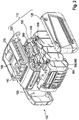
- FIG. 2 shows a battery pack 100 in the exploded view.
- the battery pack 100 has a housing 110 made up of a first housing component 120 and a second housing component 130. It can be clearly seen here that the battery pack housing 110 furthermore has a cell holder 600 with a plurality of battery cells 400 connected in a series circuit, not shown in detail, the second housing component 130 directly forming the cell holder 600.
- the cell holder 600 is positioned between the two housing components 120, 130.
- the battery pack housing 110 also has two side components 125 which, in the assembled state, hold the first housing component 120 and the second housing component 130 or the cell holder 600 together in such a way that the first housing component 120 is detached from the second housing component 130, or vice versa, is prevented.
- the Ackupack 100 is in the in Figure 2
- the embodiment shown is designed as a sliding luggage pack.
- the cell holder 600 also serves to cool the battery cells 400 and consists of a thermally conductive material, for example aluminum or a plastic.
- the cell holder 600 furthermore has sleeve-like insulating walls, so that the individual battery cells 400 are separated and electrical insulation of the individual battery cells 400 from one another can be ensured.
- the individual battery cells 400 are received at a distance from one another for mechanical fixing in the cell holder 600.
- each battery cell 400 has a jacket surface running parallel to a longitudinal axis x, the jacket surface being delimited by two end surfaces perpendicular to the longitudinal axis x on which the electrical poles of the battery cells 400 are located.
- the heat transfer resistance between the adjacent battery cells 400 and between the battery cells 400 and the cell holder 600 should be as low as possible so that the heat loss generated by the battery cells 400 can be dissipated to the outside and overheating of the battery pack inside can be prevented.
- the connection of the battery cells 400 to one another can be realized via cell connectors 500, as shown.
- the cell connectors 500 can be used to electrically interconnect the battery cells 400 with one another in parallel and / or in series.
- the cell connectors 500 are designed with such a large area that, in addition to their function, they ensure an electrical interconnection of the Ackuzellen 400 with each other in parallel and / or series, also the function of a heat spreading element 660 and can support the desired heat transfer.
- the battery pack housing 110 has a first battery cell string 410 and a second battery cell string 420.
- Both battery cell strings 410, 420 each include in the embodiment shown five electrically conductive battery cells 400 connected in series with a nominal voltage of 3.6 volts each.
- the number of battery cells 400 connected in series is variable, with the first battery cell string 410 and the second battery cell string 420 preferably each accommodating the same number of battery cells 400, as shown. In this way, it can be ensured that the nominal voltage to be provided is a multiple of the respective voltage of the first battery cell string 410 and the second battery cell string 420, so that the operating voltage required by the handheld power tool 300 is present when the battery pack 100 is inserted.
- the interface 180 of the battery pack 100 has two electrical contact elements 140 for each battery cell string 410, 420.
- a first contact element 141 and a second contact element 142 are assigned to the first battery cell string 410
- a third contact element 143 and a fourth contact element 144 are assigned to the second battery cell string 420.
- the first battery cell string 410 and the second battery cell string 420 are arranged within the battery pack housing 110 so as to be electrically insulated from one another.
- the first battery cell string 410 and the second battery cell string 420 are electrically conductively connected to one another in parallel or in a series circuit in an inserted battery pack 100 such that the voltage required by the handheld power tool 300 is applied.
- the interface 380 of the handheld power tool 300 in each case four, in principle a number of mating contact elements 340 corresponding to the number of contact elements 140 of battery pack 100, for making electrical and mechanical contact with contact elements 140 of battery pack 100.
- the mating contact elements 340 are interconnected with one another in such a way that when a battery pack 100 according to the invention is used, the drive motor 335 is supplied with the required voltage.
- the voltage required by the handheld power tool 300 corresponds to a multiple of that provided by the Ackuzellestrings 410, 420.
- the battery cells 400 of the first battery cell string 410 and of the second battery cell string 420 are connected in series with one another.
- the electrical mating contact elements 340 of the handheld power tool 300 are connected to one another in such a way that in the Hand tool 300, the second mating contact element 342 is connected to the third mating contact element 343, whereby the two battery strings 420, 410 are connected in series and a total voltage is thus applied between the first mating contact element 341 and the fourth mating contact element 344, which results from the sum of the two string voltages.
- the drive motor 335 is connected to the first and fourth mating contact elements 341, 344 via electronics 370.
- the battery cells 400 of the first battery cell string 410 and the second battery cell string 420 are connected in parallel.
- the electrical mating contact elements 340 of the handheld power tool 300 are connected to one another in such a way that when a battery pack 100 is inserted, the first mating contact element 341 is connected to the third mating contact element 343 and the second mating contact element 342 is connected to the fourth mating contact element 344.
- the nominal operating voltage of the handheld power tool 300 is then tapped between the connected first and third mating contact elements 341, 343 and the connected second and fourth mating contact elements 342, 344, 342, 344.
- the cell holder 600 forms an outside of the battery pack housing 110 in some areas, in particular the second housing component 130. It is also advantageous if the side components 125 are made of the same material as the rest of the battery pack housing 110, preferably made of a synthetic, technically usable thermoplastic such as a polyamide.
- An embodiment variant of the battery pack 100 with a cell holder 600 which directly forms the at least one first battery cell string 410 and / or the at least one second battery cell string 420 is not shown, but is fundamentally conceivable. In this way, costs can be reduced and the assembly effort can be kept low.
- the side components 125 can at least partially consist of a metal, preferably an aluminum or magnesium die-cast, in which case a sufficient one or a reliable insulation insert, for example an elastic thermally conductive element 650, must be used between the cell connectors 500 and the side components 125.
- a sufficient one or a reliable insulation insert for example an elastic thermally conductive element 650
Description
Die vorliegende Erfindung betrifft eine Handwerkzeugmaschine nach Anspruch 1.The present invention relates to a handheld power tool according to claim 1.
Elektrische Handwerkzeugmaschinen sind grundsätzlich bekannt und werden über einen Netzanschluss mit Strom versorgt. Alternativ ermöglichen Akkugeräte eine hohe Flexibilität beim Arbeiten, da sie insbesondere unabhängig von Netzstrom sind. Auf diese Weise können beispielsweise auch Außenarbeiten bequem durchgeführt werden, so dass bei einem Betrieb einer Handwerkzeugmaschine vielfach vorgesehen ist, Akkupacks einzusetzen.Electric hand machine tools are known in principle and are supplied with power via a mains connection. Alternatively, cordless tools allow a high degree of flexibility when working, as they are particularly independent of mains power. In this way, for example, outdoor work can also be carried out conveniently, so that it is often provided that battery packs are used when a handheld power tool is in operation.
Derartige Akkupacks sind grundsätzlich bekannt und weisen in der Regel eine Mehrzahl von in Parallel- und/oder Reihenschaltung verbundener wiederaufladbare Akkumulatoren, beispielsweise drei in Reihe geschaltete, zylinderförmige Lilonen-Zellen mit z.B. je 3,6 V mit einer Gesamtspannung von 10,8 V, auf. Die verbundenen Akkuzellen müssen zum einen mit einer Akkupackelektronik und zum anderen untereinander verbunden werden. Das Akkupack umfasst in der Regel ein Akkupackgehäuse in denen die Akkuzellen vorzugsweise mittels eines Zellhalters entweder vollständig oder teilweise aufgenommen sind. Alternativ bildet der Zellhalter selber ein Akkupackgehäuseelement des Akkupackgehäuses aus.Such battery packs are known in principle and generally have a plurality of rechargeable batteries connected in parallel and / or in series, for example three cylindrical Lilonen cells connected in series with, for example, 3.6 V each with a total voltage of 10.8 V, on. The connected battery cells must be connected to a battery pack electronics on the one hand and to each other on the other. The battery pack generally comprises a battery pack housing in which the battery cells are either completely or partially accommodated, preferably by means of a cell holder. Alternatively, the cell holder itself forms a battery pack housing element of the battery pack housing.
Im Rahmen dieser Anmeldung ist unter einem Akkupack somit ein vorzugsweise aus mehreren elektrisch zusammengeschalteten Akkuzellen bestehendes Akkumulatorenpaket zu verstehen, das elektrische Energie speichern kann, die für den Betrieb einer Handwerkzeugmaschine benötigte Energie liefert, und austauschbar in einer Kammer, einer Schnittstelle oder dergleichen der Handwerkzeugmaschine anbringbar ist. Insbesondere soll unter einer Schnittstelle eine Vorrichtung verstanden werden, die dazu vorgesehen ist, eine elektrische und insbesondere eine mechanische Verbindung mit einem Ladegerät und/oder einer Entladeseite, also der Handwerkzeugmaschine direkt oder indirekt herzustellen.In the context of this application, a battery pack is therefore to be understood as a battery pack which preferably consists of several electrically interconnected battery cells, which can store electrical energy, which supplies the energy required to operate a handheld power tool, and is replaceable can be attached in a chamber, an interface or the like of the handheld power tool. In particular, an interface should be understood to mean a device which is provided to establish an electrical and, in particular, a mechanical connection with a charger and / or a discharge side, that is to say the handheld power tool, directly or indirectly.
Das Ankoppeln des Akkupacks an die Handwerkzeugmaschine erfolgt durch Einstecken beziehungsweise Einschieben der Schnittstelle des Akkupacks in eine komplementäre Einsteckbuchse des Gerätegehäuses. Die Schnittstelle weist Kontaktschlitze auf, in denen Kontaktelemente angeordnet werden können. Ist die Energie des Akkupacks verbraucht, so kann er entnommen und mit einer Ladestation mit entsprechenden Gegenkontaktelementen verbunden werden. Stehen mehrere Akkupacks zur Verfügung, so ist es möglich, das entladene Akkupack aus der Handwerkzeugmaschine zu entnehmen und gegen ein geladenes auszutauschen. Dabei bestimmen in der Regel die Nennspannung und Kapazität des jeweils verwendeten Akkupacks die Leistung und Laufzeit der Handwerkzeugmaschinen.The battery pack is coupled to the handheld power tool by plugging in or pushing the interface of the battery pack into a complementary plug-in socket in the device housing. The interface has contact slots in which contact elements can be arranged. If the energy of the battery pack is used up, it can be removed and connected to a charging station with corresponding counter-contact elements. If several battery packs are available, it is possible to remove the discharged battery pack from the handheld power tool and replace it with a charged one. As a rule, the nominal voltage and capacity of the battery pack used in each case determine the power and running time of the handheld power tools.
Aus dem Stand der Technik ist einerseits bekannt, dass sich Akkupacks mit Hilfe einer Kodierung gegenüber dem Ladegerät und der Handwerkzeugmaschine, identifizieren können, so dass andere, nicht für die Handwerkzeugmaschine vorgesehene Akkupacks, z. B. solche mit einer anderen Nennspannung, seitens der Handwerkzeugmaschine nicht akzeptiert werden, damit der Akkupack und/oder die Handwerkzeugmaschine keinen Schaden nehmen.From the prior art it is known, on the one hand, that battery packs can identify themselves with the aid of a coding to the charger and the handheld power tool, so that other battery packs not intended for the handheld power tool, e.g. B. those with a different nominal voltage are not accepted by the handheld power tool so that the battery pack and / or the handheld power tool are not damaged.
Ferner ist bekannt, dass verschiedene Handwerkzeugmaschinen einer Spannungsklasse untereinander nicht kompatible Akkupacks aufweisen, wohingegen die Akkupacks von verschiedenen Handwerkzeugmaschinen innerhalb einer Volt-Klasse, beispielweise einem Stabschrauber, einem Akku-Bohrer, einer Schlagbohrmaschinen, einer Stichsägen, einem Multifunktionswerkzeug und/oder einem Bohrschrauber, oftmals kompatibel sind.
Sowohl die Akkupacks als auch die Handwerkzeugmaschinen und Ladegeräte und damit die jeweiligen Schnittstellen unterliegen einer steten Weiterentwicklung, wobei es üblich ist, dass zusätzliche Kontaktelemente und Gegenkontaktelemente in den Schnittstellen implementiert werden sollen, um zusätzliche Informationen zwischen den Geräten auszutauschen. Dabei ist es erstrebenswert, aus Gründen der Handlichkeit und Handhabbarkeit sowohl des Akkupacks als auch der Handwerkzeugmaschine, den für die Schnittstelle benötigten Bauraum so kompakt wie möglich zu halten. Darüber hinaus ergibt sich aus Gründen der Kompatibilität zu Vorgängermodellen gegebenenfalls die Forderung, die Geometrie der Schnittstelle gegenüber einem Vorgängermodell so wenig wie möglich zu ändern.Both the battery packs and the handheld power tools and chargers and thus the respective interfaces are subject to constant further development, it is common that additional contact elements and mating contact elements are to be implemented in the interfaces in order to exchange additional information between the devices. It is desirable, for reasons of handiness and manageability of both the battery pack and the handheld power tool, to keep the installation space required for the interface as compact as possible. In addition, for reasons of compatibility with previous models, there may be a requirement to change the geometry of the interface as little as possible compared to a previous model.
Grundsätzlich erweist es sich als nachteilig, dass die von den Herstellern angebotenen Handwerkzeugmaschinen üblicherweise mit jeweils unterschiedlichen Akkupacks angeboten werden, wobei die Akkupacks verschiedene Baugrößen und/ oder Nennspannungen aufweisen und jedes Akkupack bezüglich der Leistung und der Geometrie der Rast- und Kontaktelemente einem bestimmten Typ von Handwerkzeugmaschine zugeordnet ist. Die Verwendbarkeit eines solchen Akkupacks ist relativ unflexibel, weil sich der Einsatz eines jeden Akkupacks auf einen ganz bestimmten Typ einer Handwerkzeugmaschine beschränktBasically, it proves to be disadvantageous that the handheld power tools offered by the manufacturers are usually offered with different battery packs, the battery packs having different sizes and / or nominal voltages and each battery pack having a specific type of power and geometry of the latching and contact elements Hand tool is assigned. The usability of such a battery pack is relatively inflexible because the use of each battery pack is limited to a very specific type of handheld power tool
Aufgabe der Erfindung ist es, die oben genannten Nachteile zu verbessern und eine verbesserte Handwerkzeugmaschine umfassend ein lösbar mit der Handwerkzeugmaschine verbindbares Akkupack der eingangs genannten Art bereitzustellen, das bei einer Vielzahl von verschiedenen Handwerkzeugmaschinen einsetzbar ist.The object of the invention is to improve the above-mentioned disadvantages and to provide an improved handheld power tool comprising a battery pack of the type mentioned at the outset which can be detachably connected to the handheld power tool and which can be used with a large number of different handheld power tools.
Diese Aufgabe wird durch eine Handwerkzeugmaschine mit Akkupack gemäß Anspruch 1 gelöst. Vorteilhafte Ausgestaltungen, Varianten und Weiterbildungen der Erfindung sind den Unteransprüchen zu entnehmen.This object is achieved by a handheld power tool with a battery pack according to claim 1. Advantageous configurations, variants and developments of the invention can be found in the subclaims.
Erfindungsgemäß ist vorgesehen, dass eine Handwerkzeugmaschine mit Akkupack ein Akkupackgehäuse aufweist, wobei das Akkupackgehäuse mindestens zwei Akkuzellen aufnimmt. Das Akkupack ist über eine Schnittstelle mit einer Handwerkzeugmaschine und einem Ladegerät mechanisch und elektrisch verbindbar, wobei die Schnittstelle Kontaktelemente zur elektrischen und/oder mechanischen Kontaktierung korrespondierender Gegenkontaktelemente an der Handwerkzeugmaschine und/oder korrespondierender Gegenkontaktelemente an dem Ladegerät aufweist. Erfindungsgemäß ist vorgesehen, dass das Akkupackgehäuse wenigstens einen ersten Akkuzellenstrang zur Aufnahme wenigstens einer ersten Akkuzelle und wenigstens einen zweiten Akkuzellenstrang zur Aufnahme wenigstens einer zweiten Akkuzelle umfasst, wobei das Akkupackgehäuse für jeden Akkuzellenstrang wenigstens zwei elektrische Kontaktelemente aufweist. Der Vorteil der Erfindung liegt unter anderem darin, dass die erfindungsgemässe Handwerkzeugsmaschine ein Akkupack umfasst, das keine festgelegte Spannungsklasse mehr aufweist, sondern durch Reihen- und/oder Parallelschaltung von wenigsten zwei Akkuzellensträngen wenigstens zwei verschiedene Spannungsklassen, beispielsweise 18V und 36V bedienen kann. Der Bediener kann mittels eines vorhandenen 36V Akkupack auch eine 18V Handwerkzeugmaschine betreiben, wodurch er die Investition in einen 18V Akkupack und eines entsprechenden Ladegerät einsparen kann. Ferner wird
eine Bereitstellung eines Akkupacks zum Betrieb verschiedener Handwerkzeugmaschinen mit unterschiedlichen Betriebsspannungen, ermöglicht, so dass der Bediener die erfindungsgemässe Handwerkzeugmaschine mittels eines Akkupacks betreiben kann, obwohl eventuell das original Akkupack bzw. das ursprüngliche Akkupack defekt oder entladen ist. Dabei ist es von Vorteil, dass keine zwei verschiedenen Ladegeräte verwendet werden bzw. auf eine Baustelle mitgenommen werden müssen.According to the invention, it is provided that a handheld power tool with a battery pack has a battery pack housing, the battery pack housing accommodating at least two battery cells. The battery pack can be mechanically and electrically connected via an interface to a handheld power tool and a charger, the interface contact elements for making electrical and / or mechanical contact with corresponding counter-contact elements on the Has hand tool and / or corresponding mating contact elements on the charger. According to the invention it is provided that the battery pack housing comprises at least one first battery cell string for receiving at least one first battery cell and at least one second battery cell string for receiving at least one second battery cell, the battery pack housing having at least two electrical contact elements for each battery cell string. The advantage of the invention is, among other things, that the hand power tool according to the invention comprises a battery pack that no longer has a fixed voltage class, but can serve at least two different voltage classes, for example 18V and 36V, by connecting at least two battery cell strings in series and / or in parallel. Using an existing 36V battery pack, the operator can also operate an 18V handheld power tool, which saves the investment in an 18V battery pack and a corresponding charger. Furthermore,
providing a battery pack for operating various handheld power tools with different operating voltages, so that the operator can operate the handheld power tool according to the invention by means of a battery pack, although the original battery pack or the original battery pack may be defective or discharged. It is advantageous that no two different chargers are used or have to be taken to a construction site.
Der erste Akkuzellenstrang und der zweiten Akkuzellenstrang sind innerhalb des Akkupackgehäuses elektrisch voneinander isoliert angeordnet. In eine besonders bevorzugten Ausführungsform nimmt jeweils der erste Akkuzellenstrang und der zweiten Akkuzellenstrang mehrere in Reihenschaltung elektrisch leitend miteinander verbundene Akkuzellen, vorzugsweise fünf Ackuzellen, besonders bevorzugt zehn Akkuzellen auf. Dabei ist es von Vorteil, wenn der erste Akkuzellenstrang und der zweiten Akkuzellenstrang jeweils die gleiche Anzahl Akkuzellen aufnimmt.The first battery cell string and the second battery cell string are arranged within the battery pack housing, electrically insulated from one another. In a particularly preferred embodiment, the first battery cell string and the second battery cell string each accommodate a plurality of battery cells connected to one another in an electrically conductive manner in series, preferably five battery cells, particularly preferably ten battery cells. It is advantageous if the first battery cell string and the second battery cell string each hold the same number of battery cells.
Vorzugsweise sind der erste Akkuzellenstrang und der zweiten Akkuzellenstrang bei einem eingesetzten Akkupack derart in Parallel- oder in einer Reihenschaltung elektrisch leitend miteinander verbunden, dass die von der Handwerkzeugmaschine benötigte Spannung anliegt. Dabei ist die bereitzustellende Nennspannung ein Vielfaches der jeweiligen Spannung des ersten Akkuzellenstrangs und des zweiten Akkuzellenstrangs. Somit können beispielsweise erfindungsgemässe Handwerkzeugmaschinen, die für einen Betrieb mit einem etwas leistungsschwächeren Akkupack vorgesehen sind, nun alternativ mit einem leistungsstärkeren Akkupack betrieben werden, wodurch ein erfindungsgemäßes lösbar mit der Handwerkzeugmaschine verbindbares Akkupack eine Laufzeitverlängerung der Handwerkzeugmaschine erlaubt.When a battery pack is used, the first battery cell string and the second battery cell string are preferably connected to one another in an electrically conductive manner in parallel or in a series circuit in such a way that the voltage required by the handheld power tool is applied. The nominal voltage to be provided is a multiple of the respective voltage of the first battery cell string and of the second battery cell string. Thus, for example, handheld power tools according to the invention, which are intended for operation with a somewhat weaker battery pack, can now be operated alternatively with a more powerful battery pack, whereby a battery pack according to the invention that can be detachably connected to the handheld power tool allows the runtime of the handheld power tool to be extended.
Die Anzahl der Kontaktelemente der Schnittstelle des Akkupacks entspricht der Anzahl der Gegenkontaktelemente der Schnittstelle der Handwerkzeugmaschine. Somit können Akkupacks über die Schnittstelle mechanisch und elektrisch mit verschiedenen Handwerkzeugmaschinen verbunden werden, obwohl diese sich in der jeweils benötigten Nennspannung, Kapazität und/ oder Betriebsspannung unterscheiden.The number of contact elements of the interface of the battery pack corresponds to the number of mating contact elements of the interface of the handheld power tool. Thus, battery packs can be mechanically and electrically connected to various handheld power tools via the interface, although these differ in the respectively required nominal voltage, capacity and / or operating voltage.
Ferner können auf diese Weise Akkupacks verwendet werden, die ursprünglich nicht zum Betrieb der Handwerkzeugmaschine vorgesehen waren, dessen Verwendung jedoch aufgrund der variablen Nennspannung und Kapazität einen Betrieb der Handwerkzeugmaschine bewirken können.Furthermore, battery packs can be used in this way that were not originally intended for operating the handheld power tool, but whose use can cause the handheld power tool to operate due to the variable nominal voltage and capacity.
In einer bevorzugten Ausführungsform der Erfindung umfasst das Akkupackgehäuse wenigstens einen Zellenhalter zur Aufnahme des wenigstens einen ersten Akkuzellenstrangs und/oder des wenigstens einen zweiten Akkuzellenstranges, wobei vorteilhafterweise der Zellenhalter den wenigstens einen ersten Akkuzellenstrang und/oder den wenigsten einen zweiten Akkuzellenstrang unmittelbar ausbildet.In a preferred embodiment of the invention, the battery pack housing comprises at least one cell holder for receiving the at least one first battery cell string and / or the at least one second battery cell string, the cell holder advantageously directly forming the at least one first battery cell string and / or the at least one second battery cell string.
Grundsätzlich können innerhalb des Akkupacks verschiedene Ausführungsformen eines Zellenhalters verwendet werden, so dass Akkuzellen mit verschiedenen Durchmessern und Längen aufgenommen werden können und eine Anwendung des Zellenhalters in unterschiedlichen Akkupacks gewährleistet werden kann.In principle, different embodiments of a cell holder can be used within the battery pack, so that battery cells with different diameters and lengths can be accommodated and the cell holder can be used in different battery packs.
Als Akkuzellen für ein Akkupack können verschiedene Akkumulatorentypen mit unterschiedlichen Materialien, wie beispielsweise Lithium-Ionen (Li-Ion),Nickel-Cadmium (NiCd), Nickel-Metallhydrid (NiMH) oder Lithium-Polymer (LiPo), unterschiedlichen Bauformen, zum Beispiel runde, prismatische oder eckige, oder andere alternative Systeme, wie beispielsweise Brennstoffzellen, verwendet werden. Vorzugsweise werden insbesondere Lithiumionenzellen angewandt, da es insbesondere bei Lithiumionenzellen möglich ist, mehrere Akkuzellen zu Akkuzellenblöcken zusammenzufassen, in denen mehrere Akkuzellen in einer Parallel- und/oder Reihenschaltung verbunden sind. Dabei ist es besonders vorteilhaft, dass der Zellenhalter Akkuzellen mit verschiedenen Durchmessern und Längen aufnehmen kann, wodurch die Anwendung des Zellenhalters bzw. des Zellenträgers in unterschiedlichen Akkupacks erreicht werden kann.Different types of batteries with different materials, such as lithium-ion (Li-Ion), nickel-cadmium (NiCd), nickel-metal hydride (NiMH) or lithium polymer (LiPo), can be used as battery cells for a battery pack Structures, for example round, prismatic or angular, or other alternative systems, such as fuel cells, can be used. In particular, lithium-ion cells are preferably used, since it is possible in particular with lithium-ion cells to combine several battery cells to form battery cell blocks in which several battery cells are connected in parallel and / or in series. It is particularly advantageous that the cell holder can accommodate battery cells with different diameters and lengths, so that the use of the cell holder or the cell carrier in different battery packs can be achieved.
Das Akkupack ist erfindungsgemäss in einem Werkzeugsystem vorgesehen. Dementsprechend bildet eine Handwerkzeugmaschine, die ein lösbar mit der Handwerkzeugmaschine verbindbares Akkupack umfasst, den Gegenstand der Erfindung, wobei die Handwerkzeugmaschine ein Gehäuse mit einem in dem Gehäuse angeordneten Antriebsmotor zum Antrieb einer mechanischen Schnittstelle und eine in dem Gehäuse angeordnete erste Elektronik aufweist. Ferner umfasst die Handwerkzeugmaschine ein lösbar mit der Handwerkzeugmaschine verbindbares Akkupack und eine Schnittstelle mit korrespondierenden Gegenkontaktelementen zur elektrischen und mechanischen Kontaktierung mit den Kontaktelementen der Schnittstelle des Akkupacks.According to the invention, the battery pack is provided in a tool system. Accordingly, a handheld power tool comprising a battery pack that can be detachably connected to the handheld power tool forms the subject matter of the invention, the handheld power tool having a housing with a drive motor arranged in the housing for driving a mechanical interface and first electronics arranged in the housing. Furthermore, the handheld power tool comprises a battery pack that can be detachably connected to the handheld power tool and an interface with corresponding mating contact elements for making electrical and mechanical contact with the contact elements of the interface of the battery pack.
Die Schnittstelle weist wenigstens vier elektrische Gegenkontaktelemente auf, wobei die Gegenkontaktelemente derart miteinander verschaltet angeordnet sind, dass bei einem eingesetzten Akkupack der Antriebsmotor mit der benötigten Spannung versorgt wird. Die Anzahl der Gegenkontaktelemente der Schnittstelle der Handwerkzeugmaschine entspricht der Anzahl der Kontaktelemente der Schnittstelle des Akkupacks. In einer bevorzugten Ausführungsform entspricht die Betriebsspannung der Handwerkzeugmaschine ein Vielfaches der durch wenigstens einen Akkuzellenstrang bereitgestellten Spannung; und wobei die elektrischen Gegenkontaktelemente derart miteinander verbunden sind, dass bei einem eingesetzten Akkupack der Antriebsmotor mit der benötigten Spannung versorgt wird. Dabei ist es von Vorteil, dass die Handwerkzeugmaschine zumindest eine Elektronik aufweist, die es erlaubt, das über die Schnittstelle der Handwerkzeugmaschine angekoppelte Akkupack zu erkennen und/oder zu regeln.The interface has at least four electrical mating contact elements, the mating contact elements being interconnected with one another in such a way that the drive motor is supplied with the required voltage when the battery pack is inserted. The number of mating contact elements of the interface of the handheld power tool corresponds to the number of contact elements of the interface of the battery pack. In a preferred embodiment, the operating voltage of the handheld power tool corresponds to a multiple of the voltage provided by at least one battery cell string; and wherein the electrical mating contact elements are connected to one another in such a way that the drive motor is supplied with the required voltage when the battery pack is inserted. It is there It is advantageous that the handheld power tool has at least one electronic system which allows the battery pack coupled via the interface of the handheld power tool to be identified and / or controlled.
In einer bevorzugten Ausführungsvariante der vorliegenden Offenbarung ist bei einem eingesetzten Akkupack ein erstes Gegenkontaktelement der Handwerkzeugmaschine mit einem dritten Gegenkontaktelement der Handwerkzeugmaschine und/oder ein zweites Gegenkontaktelement der Handwerkzeugmaschine mit einem vierten Gegenkontaktelement der Handwerkzeugmaschine verbunden, wobei der Antriebsmotor über eine Elektronik mit dem ersten und dem dritten Gegenkontaktelement und/oder mit dem zweiten und dem vierten Gegenkontaktelement verbunden ist.In a preferred embodiment of the present disclosure, when a battery pack is used, a first mating contact element of the handheld power tool is connected to a third mating contact element of the handheld power tool and / or a second mating contact element of the handheld power tool is connected to a fourth mating contact element of the handheld power tool third mating contact element and / or is connected to the second and fourth mating contact element.
In einer alternativen Ausführungsvariante der vorliegenden Offenbarung ist bei einem eingesetzten Akkupack das zweite Gegenkontaktelement der Handwerkzeugmaschine mit dem dritten Gegenkontaktelement der Handwerkzeugmaschine verbunden, wobei der Antriebsmotor über eine Elektronik mit dem ersten und dem vierten Gegenkontaktelement verbunden ist.In an alternative embodiment of the present disclosure, when a battery pack is used, the second mating contact element of the handheld power tool is connected to the third mating contact element of the handheld power tool, the drive motor being connected to the first and fourth mating contact elements via electronics.
Unter einer Handwerkzeugmaschine sollen generell sämtliche Handwerkzeugmaschinen mit einem in Bewegung, beispielsweise in Rotation und/oder Schwingung versetzbaren Werkzeugträger, der von einem Antriebsmotor antreibbar ist, wie beispielsweise Stabschrauber, Akku-Bohrer, Schlagbohrmaschinen, Multifunktionswerkzeuge, und/ oder Bohrschrauber verstanden werden. Unter Übertragung elektrischer Energie soll in diesem Zusammenhang insbesondere verstanden werden, dass die Handwerkzeugmaschine über einen Akkupack und/oder über eine Stromkabelanbindung mit Energie versorgt wird.A hand machine tool should generally be understood to mean all hand machine tools with a tool carrier that can be set in motion, for example in rotation and / or vibration, which can be driven by a drive motor, such as rod screwdrivers, cordless drills, impact drills, multifunctional tools and / or screwdrivers. In this context, the transfer of electrical energy is to be understood in particular to mean that the hand-held power tool is supplied with energy via a battery pack and / or via a power cable connection.
Das erfindungsgemäße Akkupack ist in einem Werkzeugsystem vorgesehen. Ein Ladegerät zur Aufladung eines Ackupack ist nicht Gegenstand der vorliegenden Erfindung. Dabei weist das Ladegerät eine Schnittstelle mit Gegenkontaktelementen zur elektrischen und mechanischen Kontaktierung der Kontaktelemente des Akkupacks auf, wobei die Schnittstelle wenigstens vier elektrische Gegenkontaktelemente umfasst, die derart miteinander verschaltet angeordnet sind, dass alle Akkuzellen in den Akkuzellenstränge geladen werden, wenn das Akkupack elektrisch mit dem Ladegerät verbunden ist.The battery pack according to the invention is provided in a tool system. A charger for charging an Ackupack is not the subject of the present invention. In this case, the charger has an interface with mating contact elements for making electrical and mechanical contact with the contact elements of the battery pack, the interface comprising at least four electrical mating contact elements which are arranged interconnected so that all battery cells are charged in the battery cell strings when the battery pack is electrically connected to the charger.
Vorteilhafterweise entspricht die Anzahl der Gegenkontaktelemente der Schnittstelle des Ladegerätes der Anzahl der Kontaktelemente der Schnittstelle des Ackupacks.The number of mating contact elements of the interface of the charger advantageously corresponds to the number of contact elements of the interface of the luggage pack.
Unter einem Antriebsmotor sollen ganz allgemein alle Arten von elektrischen Verbrauchern, wie zum Beispiel ein EC-Motor, ein Linearantrieb, eine Lampe, eine Pumpe, ein Lüfter, ein Kompressor oder dergleichen verstanden werden. Der Vorteil der bürstenlosen EC-Motoren liegt unter anderem darin, dass sie zum einen nahezu wartungsfrei sind und durch ihren hohen Wirkungsgrad während eines Akkubetriebes eine längere Arbeitszeit pro Akkuladung ermöglichen, wodurch sie besonders effizient sind. Ferner können Handwerkzeugmaschinen mit EC-Motoren sehr kompakt und leicht gebaut werden, wobei es besonders vorteilhaft ist, dass auch weniger Wärmeverluste entstehen, wodurch die Geräte nicht so heiß werden wie vergleichbare Geräte, und damit langlebiger sind.A drive motor is to be understood quite generally to mean all types of electrical loads, such as, for example, an EC motor, a linear drive, a lamp, a pump, a fan, a compressor or the like. The advantage of the brushless EC motors is, among other things, that on the one hand they are almost maintenance-free and, thanks to their high degree of efficiency, allow longer working hours per battery charge, which makes them particularly efficient. Furthermore, hand-held machine tools with EC motors can be built very compact and lightweight, it being particularly advantageous that there are also fewer heat losses, as a result of which the devices do not get as hot as comparable devices and are therefore more durable.
Weitere Merkmale, Anwendungsmöglichkeiten und Vorteile der Erfindung, welche in den Ansprüchen definiert ist, ergeben sich aus der nachfolgenden Beschreibung der Ausführungsbeispiele der Erfindung, welche in den Figuren dargestellt sind.Further features, possible applications and advantages of the invention, which is defined in the claims, emerge from the following description of the exemplary embodiments of the invention, which are shown in the figures.
Die Erfindung wird im Folgenden mit Bezug auf die beigefügten Figuren genauer beschrieben, wobei für gleiche Merkmale gleiche Bezugszeichen verwendet werden. Die Zeichnungen sind schematisch und zeigen:
- Fig. 1
- beispielhaft eine Ansicht der erfindungsgemässen Handwerkzeugmaschine mit einem erfindungsgemäßen Akkupack;
- Fig. 2
- eine perspektivische Explosionsdarstellung einer ersten Ausführungsform des Akkupacks;
- Fig. 3
- eine schematische Schnittansicht einer Verbindung zwischen einem erfindungsgemäßen Akkupack und einer Schnittstelle einer ersten erfindungsgemässen Handwerkzeugmaschine; und
- Fig. 4
- eine schematische Schnittansicht einer Verbindung zwischen einem erfindungsgemäßen Akkupack und einer Schnittstelle einer zweiten erfindungsgemässen Handwerkzeugmaschine.
- Fig. 1
- an example of a view of the handheld power tool according to the invention with a battery pack according to the invention;
- Fig. 2
- a perspective exploded view of a first embodiment of the battery pack;
- Fig. 3
- a schematic sectional view of a connection between a battery pack according to the invention and an interface of a first hand power tool according to the invention; and
- Fig. 4
- a schematic sectional view of a connection between a battery pack according to the invention and an interface of a second hand power tool according to the invention.
Die
Im Bereich des Handgriffes 315 ist ein erstes Bedienelement 310 für die Energieversorgung des Antriebsmotors 335 angeordnet, wobei das erste Bedienelement 310 aus dem Gehäuse 305 für den Benutzer manuell zugänglich herausragt, so dass in einer an sich bekannten Art und Weise durch eine Druckbewegung des ersten Bedienelementes 310 eine Steuerung und/oder Regelung des Antriebsmotors bevorzugterweise in Abhängigkeit vom Verstellweg des ersten Bedienelementes 310 ermöglicht werden kann, und auch die Spannungsversorgung für den Antriebsmotor 335 ein- und/oder ausgeschaltet werden kann. Ferner weist die Handwerkzeugmaschine 300 ein zweites Bedienelement 312 in Form eines Schiebeschalters zum Einstellen der Drehrichtung des Antriebsmotors 335 der Handwerkzeugmaschine 300 auf. Das zweite Bedienelement 312 ist senkrecht zur Drehachse x der Antriebswelle, insbesondere der Werkzeugaufnahme 320 der Handwerkzeugmaschine 300, verschieblich angeordnet, so dass das zweite Bedienelement 312 bei Betätigung zwischen einer ersten Position, einer zweiten Position und einer dritten Position hin und her bewegt werden kann. Dabei legen jeweils die erste und zweite Position eine Drehrichtung des Antriebsmotors fest. Somit kann der Benutzer der Handwerkzeugmaschine 300 bereits anhand der Positionen des zweiten Bedienelements 312 erkennen, in welchem Arbeitsmodus die Handwerkzeugmaschine 300 arbeitet. Zusätzlich weist das zweite Schaltelement zwischen der ersten Position und der zweiten Position eine dritte Position, beispielsweise eine Mittelstellung, auf, wobei in der dritten Position eine elektrische, elektromechanische und/oder mechanische Unterbrechung des Motorstroms erfolgt. So kann zum Beispiel die Bedienung des ersten Schaltelementes 310 mechanisch gesperrt sein, wobei das zweite Bedienelement 312 bei Bewegung in eine dritte Position verriegelnd auf das erste Schaltelement 310 wirkt. Dabei kann das zweite Bedienelement 312 wie dargestellt als Schiebeschalter oder alternativ als Kippschalter ausgeführt sein.In the area of the
Das erste Bedienelement 310 und das zweite Bedienelement 312 sind entlang der Drehachse x derart angeordnet, dass es möglich ist, sowohl das erste als auch das zweite Bedienelement 310, 312 mit dem Zeigefinger oder Mittelfinger zu betätigen. Dabei ist der Abstand zwischen dem ersten Bedienelement 310 und dem zweiten Bedienelement 312 so gewählt, dass eine Einhandbedienung der Handwerkzeugmaschine 300 möglich ist. Beide Bedienelemente 310, 312 sind ferner in einem Bereich unterhalb der Drehachse x angeordnet und ragen aus dem Gehäuse 305 heraus.The
In der in der
Das in
Zum lösbaren Anbringen des Akkupacks 100 an einer erfindungsgemässen Handwerkzeugmaschine 300 oder an einem Ladegerät, welches nicht Teil der vorliegenden Erfindung ist, weist das Akkupack 100 eine Schnittstelle 180 zur lösbaren mechanischen und elektrischen Verbindung mit einer korrespondierenden Schnittstelle 380 der Handwerkzeugmaschine 300 oder einer korrespondierende Schnittstelle des Ladegerätes auf. Beim Anbringen des Akkupacks 100 werden Aufnahmemittel, z. B. Führungsnuten und Führungsrippen, der Handwerkzeugmaschine 300 oder des Ladegerätes zur Aufnahme der korrespondierenden Führungselemente des Akkupacks 100 mit diesen in Eingriff gebracht, wobei das Akkupack 100 entlang der Aufnahmemittel eingeführt und die Schnittstelle 180 des Akkupacks 100 in die korrespondierende Schnittstelle 380 der Handwerkzeugmaschine 300 oder die korrespondierende Schnittstelle des Ladegerätes geschoben wird. Über die Schnittstellen 180, 380 kann das Akkupack 100 der Handwerkzeugmaschine 300 und/oder dem Ladegerät zugeordnet werden.For releasable attachment of the
Wie in
Zum Verriegeln des Akkupacks 100 am Handgriff 315 der Handwerkzeugmaschine 300 wird das Akkupack 100 entlang des Handgriffs 315 geschoben, und zwar entlang einer unteren, im Wesentlichen senkrecht zur Längsrichtung y des Handgriffs 315 ausgerichteten Außenfläche des Handgriffs 315. In der in der Figur 1 gezeigten Position ist das Akkupack 100 durch Verriegelungsmittel am Handgriff 315 verriegelt. Die Verriegelungsmittel umfassen unter anderem ein in
Wie in
Die Verbindung der Akkuzellen 400 untereinander kann wie abgebildet über Zellverbinder 500 realisiert werden. Durch die Zellverbinder 500 kann eine elektrische Verschaltung der Akkuzellen 400 untereinander in Parallel- und/oder Reihenschaltung vorgenommen werden. Obwohl in den Figuren nicht im Detail dargestellt, ist es vorteilhaft, wenn die Zellverbinder 500 derart großflächig ausgestaltet sind, dass sie, neben ihrer Funktion eine elektrische Verschaltung der Ackuzellen 400 untereinander in Parallel- und/oder Reihenschaltung zu gewährleisten, auch die Funktion eines Wärmespreizelementes 660 übernehmen und den erwünschten Wärmeübergang unterstützen können.The connection of the
Wie in den
In der in
Der Antriebsmotor 335 ist über eine Elektronik 370 mit dem ersten und dem vierten Gegenkontaktelement 341, 344 verbunden.The
In der in
Grundsätzlich von Vorteil ist, wenn der Zellenhalter 600, wie in der
Obwohl die Erfindung durch die bevorzugten Ausführungsbeispiele im Detail näher erläutert wurde, können vom Fachmann auch andere Kombinationen der genannten Merkmale vorgesehen sein, ohne den in den Ansprüchen definierten Schutzumfang der Erfindung zu verlassen.Although the invention has been explained in more detail by means of the preferred exemplary embodiments, other combinations of the features mentioned can also be provided by the person skilled in the art without departing from the scope of protection of the invention defined in the claims.
Claims (10)
- Portable power tool (300) comprising a housing (305), a drive motor (335), arranged in the housing (305), for driving a mechanical interface (320), a first electronic system (370) arranged in the housing (305), a battery pack (100) that is releasably connectable to the portable power tool (300) and has a battery pack housing (110), wherein the battery pack housing (110) holds at least two battery cells (400); and an interface (180) for establishing a mechanical and electrical connection of the battery pack (100) to a portable power tool (300) and a charger; wherein the interface (180) has contact elements (140) for making electrical and/or mechanical contact with corresponding mating contact elements (340) on the portable power tool (300) and/or corresponding mating contact elements on the charger; wherein the battery pack housing (110) comprises at least one first battery cell string (410) for holding at least one first battery cell (400) and at least one second battery cell string (420) for holding at least one second battery cell (400); wherein the at least first battery cell string (410) and the at least second battery cell string (420) are arranged in a manner electrically insulated from one another within the battery pack housing (110), wherein the battery pack housing (110) has at least two electrical contact elements (140) for each battery cell string (410, 420), wherein the portable power tool (300) has an interface (380) with mating contact elements (340) for making electrical and mechanical contact with the contact elements (140) of the battery pack (100), characterized in that the interface (380) has at least four electrical mating contact elements (340); wherein the mating contact elements (340) are arranged in an interconnected manner such that, with a battery pack (100) inserted, the drive motor (335) is supplied with the required voltage.
- Portable power tool (300) according to Claim 1, characterized in that each of the at least first battery cell string (410) and the at least second battery cell string (420) holds a plurality of battery cells (400) that are connected together in series in an electrically conducting manner, preferably five battery cells (400), particularly preferably ten battery cells (400).
- Portable power tool (300) according to either of Claims 1 and 2, characterized in that the at least first battery cell string (410) and the at least second battery cell string (420) each hold the same number of battery cells (400).
- Portable power tool (300) according to one of Claims 1 to 3, characterized in that the at least first battery cell string (410) and the at least second battery cell string (420), with a battery pack (100) inserted, are connected together in parallel or in series in an electrically conducting manner such that the operating voltage required by the portable power tool (300) is applied.
- Portable power tool (300) according to one of Claims 1 to 4, characterized in that the number of contact elements (140) of the interface (180) of the battery pack (100) corresponds at least to the number of mating contact elements (340) of the interface (380) of the portable power tool (300).
- Portable power tool (300) according to one of Claims 1 to 5, characterized in that the battery pack housing (110) comprises at least one cell holder (600) for holding the at least one first battery cell string (410) and/or the at least one second battery cell string (420).
- Portable power tool (300) according to one of the preceding claims, characterized in that the number of contact elements (140) of the interface (180) of the battery pack (100) corresponds at least to the number of mating contact elements (340) of the interface (380) of the portable power tool (300).
- Portable power tool (300) according to one of the preceding claims, characterized in that the operating voltage of the portable power tool (300) is a multiple of the voltage provided by at least one battery cell string (410, 420); and wherein the electrical mating contact elements (340) are connected together such that, with a battery pack (100) inserted, the drive motor (335) is supplied with the required voltage.
- Portable power tool (300) according to one of the preceding claims, characterized in that, with a battery pack (100) inserted, a first mating contact element (341) of the portable power tool (300) is connected to a third mating contact element (343) of the portable power tool (300) and/or a second mating contact element (342) of the portable power tool (300) is connected to a fourth mating contact element (344) of the portable power tool (300), wherein the drive motor (335) is connected to the first and the third mating contact element (341, 343) and/or to the second and the fourth mating contact element (342, 344) via an electronic system (370).
- Portable power tool (300) according to one of the preceding claims, characterized in that, with a battery pack (100) inserted, a second mating contact element (342) of the portable power tool (300) is connected to a third mating contact element (343) of the portable power tool (300), wherein the drive motor (335) is connected to the first and the fourth mating contact element (342, 344) .
Applications Claiming Priority (2)
| Application Number | Priority Date | Filing Date | Title |
|---|---|---|---|
| DE102016205568.2A DE102016205568A1 (en) | 2016-04-05 | 2016-04-05 | Hand tool and battery pack for a hand tool |
| PCT/EP2017/057430 WO2017174419A1 (en) | 2016-04-05 | 2017-03-29 | Handheld power tool and rechargeable battery pack for a handheld power tool |
Publications (2)
| Publication Number | Publication Date |
|---|---|
| EP3440723A1 EP3440723A1 (en) | 2019-02-13 |
| EP3440723B1 true EP3440723B1 (en) | 2021-09-08 |
Family
ID=58464531
Family Applications (1)
| Application Number | Title | Priority Date | Filing Date |
|---|---|---|---|
| EP17715090.1A Active EP3440723B1 (en) | 2016-04-05 | 2017-03-29 | Handheld power tool |
Country Status (4)
| Country | Link |
|---|---|
| US (1) | US10797281B2 (en) |
| EP (1) | EP3440723B1 (en) |
| DE (1) | DE102016205568A1 (en) |
| WO (1) | WO2017174419A1 (en) |
Families Citing this family (8)
| Publication number | Priority date | Publication date | Assignee | Title |
|---|---|---|---|---|
| NZ742209A (en) | 2015-12-11 | 2019-04-26 | Milwaukee Electric Tool Corp | Method and apparatus for connecting a plurality of battery cells in series or parallel |
| DE102017210557A1 (en) * | 2017-06-22 | 2018-12-27 | Robert Bosch Gmbh | Battery pack interface device |
| CN110768313A (en) * | 2018-07-25 | 2020-02-07 | 南京奥视威电子科技股份有限公司 | Battery and external part |
| CN113681518A (en) * | 2020-05-18 | 2021-11-23 | 南京德朔实业有限公司 | Electric tool |
| EP4012828A4 (en) * | 2020-09-30 | 2023-06-28 | Nanjing Chervon Industry Co., Ltd. | Battery pack, electric tool system, and charging system |
| EP4005739A1 (en) * | 2020-11-27 | 2022-06-01 | Hilti Aktiengesellschaft | Battery-operated handheld machine tool, battery unit for a handheld machine tool, system with the handheld machine tool and a battery unit, charging device for a battery unit, and system comprising a battery unit and a charging device |
| US20220190767A1 (en) * | 2020-12-11 | 2022-06-16 | Snap-On Incorporated | Tool brownout management |
| EP4030522A1 (en) * | 2021-01-15 | 2022-07-20 | VARTA Microbattery GmbH | Battery module, modular battery system and method for assembling a modular battery system |
Family Cites Families (11)
| Publication number | Priority date | Publication date | Assignee | Title |
|---|---|---|---|---|
| US5227262A (en) * | 1992-07-08 | 1993-07-13 | Yaacov Ozer | Universal camcorder battery pack |
| US6729415B1 (en) | 2003-04-18 | 2004-05-04 | Techway Industrial Co., Ltd. | Portable electric tool with bi-directionally mountable battery holder |
| US7629766B2 (en) * | 2006-07-17 | 2009-12-08 | Bbs Licensing, Inc. | Adapter system for battery-powered tools |
| DE102007042398A1 (en) * | 2007-09-06 | 2009-03-12 | Robert Bosch Gmbh | charger |
| JP5432761B2 (en) * | 2010-02-12 | 2014-03-05 | 株式会社マキタ | Electric tool powered by multiple battery packs |
| WO2013139372A1 (en) * | 2012-03-19 | 2013-09-26 | Husqvarna Ab | Power adapter for cordless power tools |
| US20150332839A1 (en) * | 2012-12-21 | 2015-11-19 | Robert Bosch Gmbh | Inductive charging coil device |
| GB201403971D0 (en) | 2014-03-06 | 2014-04-23 | 7Rdd Ltd | Portable power supply improvements |
| DE102015201574A1 (en) * | 2014-04-17 | 2015-10-22 | Robert Bosch Gmbh | battery device |
| CA2891840C (en) * | 2014-05-16 | 2022-10-25 | Techtronic Power Tools Technology Limited | Multi-battery pack for power tools |
| DE102014217987A1 (en) * | 2014-09-09 | 2016-03-10 | Robert Bosch Gmbh | Battery pack for a hand tool |
-
2016
- 2016-04-05 DE DE102016205568.2A patent/DE102016205568A1/en active Pending
-
2017
- 2017-03-29 US US16/091,299 patent/US10797281B2/en active Active
- 2017-03-29 WO PCT/EP2017/057430 patent/WO2017174419A1/en active Application Filing
- 2017-03-29 EP EP17715090.1A patent/EP3440723B1/en active Active
Also Published As
| Publication number | Publication date |
|---|---|
| EP3440723A1 (en) | 2019-02-13 |
| US10797281B2 (en) | 2020-10-06 |
| DE102016205568A1 (en) | 2017-10-05 |
| US20190123314A1 (en) | 2019-04-25 |
| WO2017174419A1 (en) | 2017-10-12 |
Similar Documents
| Publication | Publication Date | Title |
|---|---|---|
| EP3440723B1 (en) | Handheld power tool | |
| EP3424095B1 (en) | Battery pack for handheld powertool | |
| EP2996174B1 (en) | Battery pack for electric appliance | |
| EP3393722B1 (en) | Hand power tool | |
| EP3266053B1 (en) | Battery pack for a power tool | |
| DE112013006568B4 (en) | electric tool | |
| DE112015001742B4 (en) | Electric power tool | |
| EP3266054B1 (en) | Battery pack for a power tool | |
| DE102016203431A1 (en) | Battery pack for a hand tool and method for producing a battery pack for a hand tool | |
| DE102014217991A1 (en) | Cell carrier for a battery pack of a power tool | |
| DE102015207730A1 (en) | Charger for a battery pack of a hand tool | |
| WO2017148737A1 (en) | Battery pack for a hand-held power tool | |
| DE202016106018U1 (en) | Coupling device for a hand tool | |
| DE102015204048A1 (en) | Battery pack for a hand tool | |
| EP3560063A1 (en) | Hand tool system | |
| EP4050716A2 (en) | Cell holder and battery pack with a cell holder | |
| WO2019063212A1 (en) | Battery pack | |
| DE202015105602U1 (en) | Hand tool | |
| DE102016209965A1 (en) | Printed circuit board and charger with a printed circuit board for a battery pack | |
| DE3742240A1 (en) | Electrical hand tool having an accumulator section (rechargeable battery section) | |
| WO2021144153A1 (en) | Battery pack for a hand-held power tool, hand-held power tool and charging device | |
| DE102015218259A1 (en) | Battery pack for a hand tool | |
| DE202006004935U1 (en) | Battery-powered hand tool has tool holder for accommodating accessory tools and is connectable to casing by means of locking element and/or can be connectable to battery charging device | |
| DE102014222370A1 (en) | Battery pack for a hand tool | |
| DE202006004936U1 (en) | Hand tool |
Legal Events
| Date | Code | Title | Description |
|---|---|---|---|
| STAA | Information on the status of an ep patent application or granted ep patent |
Free format text: STATUS: UNKNOWN |
|
| STAA | Information on the status of an ep patent application or granted ep patent |
Free format text: STATUS: THE INTERNATIONAL PUBLICATION HAS BEEN MADE |
|
| PUAI | Public reference made under article 153(3) epc to a published international application that has entered the european phase |
Free format text: ORIGINAL CODE: 0009012 |
|
| STAA | Information on the status of an ep patent application or granted ep patent |
Free format text: STATUS: REQUEST FOR EXAMINATION WAS MADE |
|
| 17P | Request for examination filed |
Effective date: 20181105 |
|
| AK | Designated contracting states |
Kind code of ref document: A1 Designated state(s): AL AT BE BG CH CY CZ DE DK EE ES FI FR GB GR HR HU IE IS IT LI LT LU LV MC MK MT NL NO PL PT RO RS SE SI SK SM TR |
|
| AX | Request for extension of the european patent |
Extension state: BA ME |
|
| DAV | Request for validation of the european patent (deleted) | ||
| DAX | Request for extension of the european patent (deleted) | ||
| RAP1 | Party data changed (applicant data changed or rights of an application transferred) |
Owner name: ROBERT BOSCH GMBH |
|
| STAA | Information on the status of an ep patent application or granted ep patent |
Free format text: STATUS: EXAMINATION IS IN PROGRESS |
|
| STAA | Information on the status of an ep patent application or granted ep patent |
Free format text: STATUS: EXAMINATION IS IN PROGRESS |
|
| 17Q | First examination report despatched |
Effective date: 20201005 |
|
| REG | Reference to a national code |
Ref country code: DE Ref legal event code: R079 Ref document number: 502017011437 Country of ref document: DE Free format text: PREVIOUS MAIN CLASS: H01M0002100000 Ipc: H01M0010460000 |
|
| GRAP | Despatch of communication of intention to grant a patent |
Free format text: ORIGINAL CODE: EPIDOSNIGR1 |
|
| STAA | Information on the status of an ep patent application or granted ep patent |
Free format text: STATUS: GRANT OF PATENT IS INTENDED |
|
| RIC1 | Information provided on ipc code assigned before grant |
Ipc: B25F 5/00 20060101ALI20210303BHEP Ipc: H02J 7/00 20060101ALI20210303BHEP Ipc: H01M 50/213 20210101ALI20210303BHEP Ipc: H01M 10/46 20060101AFI20210303BHEP |
|
| INTG | Intention to grant announced |
Effective date: 20210329 |
|
| GRAS | Grant fee paid |
Free format text: ORIGINAL CODE: EPIDOSNIGR3 |
|
| GRAA | (expected) grant |
Free format text: ORIGINAL CODE: 0009210 |
|
| STAA | Information on the status of an ep patent application or granted ep patent |
Free format text: STATUS: THE PATENT HAS BEEN GRANTED |
|
| AK | Designated contracting states |
Kind code of ref document: B1 Designated state(s): AL AT BE BG CH CY CZ DE DK EE ES FI FR GB GR HR HU IE IS IT LI LT LU LV MC MK MT NL NO PL PT RO RS SE SI SK SM TR |
|
| REG | Reference to a national code |
Ref country code: GB Ref legal event code: FG4D Free format text: NOT ENGLISH |
|
| REG | Reference to a national code |
Ref country code: AT Ref legal event code: REF Ref document number: 1429385 Country of ref document: AT Kind code of ref document: T Effective date: 20210915 Ref country code: CH Ref legal event code: EP |
|
| REG | Reference to a national code |
Ref country code: IE Ref legal event code: FG4D Free format text: LANGUAGE OF EP DOCUMENT: GERMAN |
|
| REG | Reference to a national code |
Ref country code: DE Ref legal event code: R096 Ref document number: 502017011437 Country of ref document: DE |
|
| REG | Reference to a national code |
Ref country code: LT Ref legal event code: MG9D |
|
| REG | Reference to a national code |
Ref country code: NL Ref legal event code: MP Effective date: 20210908 |
|
| PG25 | Lapsed in a contracting state [announced via postgrant information from national office to epo] |
Ref country code: SE Free format text: LAPSE BECAUSE OF FAILURE TO SUBMIT A TRANSLATION OF THE DESCRIPTION OR TO PAY THE FEE WITHIN THE PRESCRIBED TIME-LIMIT Effective date: 20210908 Ref country code: RS Free format text: LAPSE BECAUSE OF FAILURE TO SUBMIT A TRANSLATION OF THE DESCRIPTION OR TO PAY THE FEE WITHIN THE PRESCRIBED TIME-LIMIT Effective date: 20210908 Ref country code: HR Free format text: LAPSE BECAUSE OF FAILURE TO SUBMIT A TRANSLATION OF THE DESCRIPTION OR TO PAY THE FEE WITHIN THE PRESCRIBED TIME-LIMIT Effective date: 20210908 Ref country code: NO Free format text: LAPSE BECAUSE OF FAILURE TO SUBMIT A TRANSLATION OF THE DESCRIPTION OR TO PAY THE FEE WITHIN THE PRESCRIBED TIME-LIMIT Effective date: 20211208 Ref country code: ES Free format text: LAPSE BECAUSE OF FAILURE TO SUBMIT A TRANSLATION OF THE DESCRIPTION OR TO PAY THE FEE WITHIN THE PRESCRIBED TIME-LIMIT Effective date: 20210908 Ref country code: FI Free format text: LAPSE BECAUSE OF FAILURE TO SUBMIT A TRANSLATION OF THE DESCRIPTION OR TO PAY THE FEE WITHIN THE PRESCRIBED TIME-LIMIT Effective date: 20210908 Ref country code: BG Free format text: LAPSE BECAUSE OF FAILURE TO SUBMIT A TRANSLATION OF THE DESCRIPTION OR TO PAY THE FEE WITHIN THE PRESCRIBED TIME-LIMIT Effective date: 20211208 Ref country code: LT Free format text: LAPSE BECAUSE OF FAILURE TO SUBMIT A TRANSLATION OF THE DESCRIPTION OR TO PAY THE FEE WITHIN THE PRESCRIBED TIME-LIMIT Effective date: 20210908 |
|
| PG25 | Lapsed in a contracting state [announced via postgrant information from national office to epo] |
Ref country code: LV Free format text: LAPSE BECAUSE OF FAILURE TO SUBMIT A TRANSLATION OF THE DESCRIPTION OR TO PAY THE FEE WITHIN THE PRESCRIBED TIME-LIMIT Effective date: 20210908 Ref country code: GR Free format text: LAPSE BECAUSE OF FAILURE TO SUBMIT A TRANSLATION OF THE DESCRIPTION OR TO PAY THE FEE WITHIN THE PRESCRIBED TIME-LIMIT Effective date: 20211209 |
|
| REG | Reference to a national code |
Ref country code: DE Ref legal event code: R026 Ref document number: 502017011437 Country of ref document: DE |
|
| PG25 | Lapsed in a contracting state [announced via postgrant information from national office to epo] |
Ref country code: IS Free format text: LAPSE BECAUSE OF FAILURE TO SUBMIT A TRANSLATION OF THE DESCRIPTION OR TO PAY THE FEE WITHIN THE PRESCRIBED TIME-LIMIT Effective date: 20220108 Ref country code: SM Free format text: LAPSE BECAUSE OF FAILURE TO SUBMIT A TRANSLATION OF THE DESCRIPTION OR TO PAY THE FEE WITHIN THE PRESCRIBED TIME-LIMIT Effective date: 20210908 Ref country code: SK Free format text: LAPSE BECAUSE OF FAILURE TO SUBMIT A TRANSLATION OF THE DESCRIPTION OR TO PAY THE FEE WITHIN THE PRESCRIBED TIME-LIMIT Effective date: 20210908 Ref country code: RO Free format text: LAPSE BECAUSE OF FAILURE TO SUBMIT A TRANSLATION OF THE DESCRIPTION OR TO PAY THE FEE WITHIN THE PRESCRIBED TIME-LIMIT Effective date: 20210908 Ref country code: PT Free format text: LAPSE BECAUSE OF FAILURE TO SUBMIT A TRANSLATION OF THE DESCRIPTION OR TO PAY THE FEE WITHIN THE PRESCRIBED TIME-LIMIT Effective date: 20220110 Ref country code: PL Free format text: LAPSE BECAUSE OF FAILURE TO SUBMIT A TRANSLATION OF THE DESCRIPTION OR TO PAY THE FEE WITHIN THE PRESCRIBED TIME-LIMIT Effective date: 20210908 Ref country code: NL Free format text: LAPSE BECAUSE OF FAILURE TO SUBMIT A TRANSLATION OF THE DESCRIPTION OR TO PAY THE FEE WITHIN THE PRESCRIBED TIME-LIMIT Effective date: 20210908 Ref country code: EE Free format text: LAPSE BECAUSE OF FAILURE TO SUBMIT A TRANSLATION OF THE DESCRIPTION OR TO PAY THE FEE WITHIN THE PRESCRIBED TIME-LIMIT Effective date: 20210908 Ref country code: CZ Free format text: LAPSE BECAUSE OF FAILURE TO SUBMIT A TRANSLATION OF THE DESCRIPTION OR TO PAY THE FEE WITHIN THE PRESCRIBED TIME-LIMIT Effective date: 20210908 Ref country code: AL Free format text: LAPSE BECAUSE OF FAILURE TO SUBMIT A TRANSLATION OF THE DESCRIPTION OR TO PAY THE FEE WITHIN THE PRESCRIBED TIME-LIMIT Effective date: 20210908 |
|
| PLBI | Opposition filed |
Free format text: ORIGINAL CODE: 0009260 |
|
| PLAX | Notice of opposition and request to file observation + time limit sent |
Free format text: ORIGINAL CODE: EPIDOSNOBS2 |
|
| 26 | Opposition filed |
Opponent name: STANLEY BLACK & DECKER, INC. Effective date: 20220531 |
|
| PG25 | Lapsed in a contracting state [announced via postgrant information from national office to epo] |
Ref country code: DK Free format text: LAPSE BECAUSE OF FAILURE TO SUBMIT A TRANSLATION OF THE DESCRIPTION OR TO PAY THE FEE WITHIN THE PRESCRIBED TIME-LIMIT Effective date: 20210908 |
|
| PG25 | Lapsed in a contracting state [announced via postgrant information from national office to epo] |
Ref country code: SI Free format text: LAPSE BECAUSE OF FAILURE TO SUBMIT A TRANSLATION OF THE DESCRIPTION OR TO PAY THE FEE WITHIN THE PRESCRIBED TIME-LIMIT Effective date: 20210908 |
|
| PLBB | Reply of patent proprietor to notice(s) of opposition received |
Free format text: ORIGINAL CODE: EPIDOSNOBS3 |
|
| PG25 | Lapsed in a contracting state [announced via postgrant information from national office to epo] |
Ref country code: MC Free format text: LAPSE BECAUSE OF FAILURE TO SUBMIT A TRANSLATION OF THE DESCRIPTION OR TO PAY THE FEE WITHIN THE PRESCRIBED TIME-LIMIT Effective date: 20210908 |
|
| REG | Reference to a national code |
Ref country code: CH Ref legal event code: PL |
|
| REG | Reference to a national code |
Ref country code: BE Ref legal event code: MM Effective date: 20220331 |
|
| PG25 | Lapsed in a contracting state [announced via postgrant information from national office to epo] |
Ref country code: LU Free format text: LAPSE BECAUSE OF NON-PAYMENT OF DUE FEES Effective date: 20220329 Ref country code: LI Free format text: LAPSE BECAUSE OF NON-PAYMENT OF DUE FEES Effective date: 20220331 Ref country code: IT Free format text: LAPSE BECAUSE OF FAILURE TO SUBMIT A TRANSLATION OF THE DESCRIPTION OR TO PAY THE FEE WITHIN THE PRESCRIBED TIME-LIMIT Effective date: 20210908 Ref country code: IE Free format text: LAPSE BECAUSE OF NON-PAYMENT OF DUE FEES Effective date: 20220329 Ref country code: CH Free format text: LAPSE BECAUSE OF NON-PAYMENT OF DUE FEES Effective date: 20220331 |
|
| PG25 | Lapsed in a contracting state [announced via postgrant information from national office to epo] |
Ref country code: BE Free format text: LAPSE BECAUSE OF NON-PAYMENT OF DUE FEES Effective date: 20220331 |
|
| PGFP | Annual fee paid to national office [announced via postgrant information from national office to epo] |
Ref country code: FR Payment date: 20230320 Year of fee payment: 7 Ref country code: AT Payment date: 20230317 Year of fee payment: 7 |
|
| PGFP | Annual fee paid to national office [announced via postgrant information from national office to epo] |
Ref country code: GB Payment date: 20230323 Year of fee payment: 7 |
|
| P01 | Opt-out of the competence of the unified patent court (upc) registered |
Effective date: 20230509 |
|
| PGFP | Annual fee paid to national office [announced via postgrant information from national office to epo] |
Ref country code: DE Payment date: 20230524 Year of fee payment: 7 |
|
| APAH | Appeal reference modified |
Free format text: ORIGINAL CODE: EPIDOSCREFNO |
|
| APBM | Appeal reference recorded |
Free format text: ORIGINAL CODE: EPIDOSNREFNO |
|
| APBP | Date of receipt of notice of appeal recorded |
Free format text: ORIGINAL CODE: EPIDOSNNOA2O |
|
| PG25 | Lapsed in a contracting state [announced via postgrant information from national office to epo] |
Ref country code: HU Free format text: LAPSE BECAUSE OF FAILURE TO SUBMIT A TRANSLATION OF THE DESCRIPTION OR TO PAY THE FEE WITHIN THE PRESCRIBED TIME-LIMIT; INVALID AB INITIO Effective date: 20170329 |