EP3440295B1 - Hinge fitting with a check for tilt and turn windows - Google Patents
Hinge fitting with a check for tilt and turn windows Download PDFInfo
- Publication number
- EP3440295B1 EP3440295B1 EP17712764.4A EP17712764A EP3440295B1 EP 3440295 B1 EP3440295 B1 EP 3440295B1 EP 17712764 A EP17712764 A EP 17712764A EP 3440295 B1 EP3440295 B1 EP 3440295B1
- Authority
- EP
- European Patent Office
- Prior art keywords
- scissor
- wing
- eccentric
- spring element
- link
- Prior art date
- Legal status (The legal status is an assumption and is not a legal conclusion. Google has not performed a legal analysis and makes no representation as to the accuracy of the status listed.)
- Active
Links
Images


Classifications
-
- E—FIXED CONSTRUCTIONS
- E05—LOCKS; KEYS; WINDOW OR DOOR FITTINGS; SAFES
- E05D—HINGES OR SUSPENSION DEVICES FOR DOORS, WINDOWS OR WINGS
- E05D15/00—Suspension arrangements for wings
- E05D15/48—Suspension arrangements for wings allowing alternative movements
- E05D15/52—Suspension arrangements for wings allowing alternative movements for opening about a vertical as well as a horizontal axis
- E05D15/5205—Suspension arrangements for wings allowing alternative movements for opening about a vertical as well as a horizontal axis with horizontally-extending checks
-
- E—FIXED CONSTRUCTIONS
- E05—LOCKS; KEYS; WINDOW OR DOOR FITTINGS; SAFES
- E05F—DEVICES FOR MOVING WINGS INTO OPEN OR CLOSED POSITION; CHECKS FOR WINGS; WING FITTINGS NOT OTHERWISE PROVIDED FOR, CONCERNED WITH THE FUNCTIONING OF THE WING
- E05F7/00—Accessories for wings not provided for in other groups of this subclass
- E05F7/005—Aligning devices for wings
-
- E—FIXED CONSTRUCTIONS
- E05—LOCKS; KEYS; WINDOW OR DOOR FITTINGS; SAFES
- E05Y—INDEXING SCHEME RELATING TO HINGES OR OTHER SUSPENSION DEVICES FOR DOORS, WINDOWS OR WINGS AND DEVICES FOR MOVING WINGS INTO OPEN OR CLOSED POSITION, CHECKS FOR WINGS AND WING FITTINGS NOT OTHERWISE PROVIDED FOR, CONCERNED WITH THE FUNCTIONING OF THE WING
- E05Y2600/00—Mounting or coupling arrangements for elements provided for in this subclass
- E05Y2600/10—Adjustable or movable
- E05Y2600/11—Adjustable or movable by automatically acting means
-
- E—FIXED CONSTRUCTIONS
- E05—LOCKS; KEYS; WINDOW OR DOOR FITTINGS; SAFES
- E05Y—INDEXING SCHEME RELATING TO HINGES OR OTHER SUSPENSION DEVICES FOR DOORS, WINDOWS OR WINGS AND DEVICES FOR MOVING WINGS INTO OPEN OR CLOSED POSITION, CHECKS FOR WINGS AND WING FITTINGS NOT OTHERWISE PROVIDED FOR, CONCERNED WITH THE FUNCTIONING OF THE WING
- E05Y2800/00—Details, accessories and auxiliary operations not otherwise provided for
- E05Y2800/37—Length, width adjustment
-
- E—FIXED CONSTRUCTIONS
- E05—LOCKS; KEYS; WINDOW OR DOOR FITTINGS; SAFES
- E05Y—INDEXING SCHEME RELATING TO HINGES OR OTHER SUSPENSION DEVICES FOR DOORS, WINDOWS OR WINGS AND DEVICES FOR MOVING WINGS INTO OPEN OR CLOSED POSITION, CHECKS FOR WINGS AND WING FITTINGS NOT OTHERWISE PROVIDED FOR, CONCERNED WITH THE FUNCTIONING OF THE WING
- E05Y2900/00—Application of doors, windows, wings or fittings thereof
- E05Y2900/10—Application of doors, windows, wings or fittings thereof for buildings or parts thereof
- E05Y2900/13—Application of doors, windows, wings or fittings thereof for buildings or parts thereof characterised by the type of wing
- E05Y2900/148—Windows
Definitions
- the invention relates to a fitting arrangement according to the preamble of claim 1.
- the FR 2167494 A5 shows a fitting arrangement according to the preamble, in which the opening device for a rotatable and tiltable sash of a window or a door has a scissor cuff fixedly attached to the sash, which is coupled to an opening arm in a rotary / sliding bearing.
- the extension arm has at the end in a coupling piece a hinge hole for a hinge pin for storage in a frame on the bearing block.
- a handlebar which is pivotably mounted on the handlebar and is assigned to the scissor stay in an adjustable bracket, is also effective between the scissor stay and the extension arm.
- the handlebar is aligned in the rotational position of the opening device parallel to the scissor stay and the extension arm and causes the extension arm to be supported on the forend over the tab.
- the tab is supported by an eccentric on the scissor cuff and can be secured with a locking screw relative to the scissor cuff.
- the tab In order to change the relative position of the wing relative to the bearing block, the tab can be moved relative to the scissor stay. To do this, you must first loosen the locking screw and adjust the eccentric accordingly.
- the locking screw and eccentric are only accessible when the sash is turned and tilted, whereby the masonry makes access more difficult.
- From the DE 19718325 C1 shows an independently acting adjustment device in which two mutually movable hinge parts are provided.
- a first hinge part is attached to the frame and a second is assigned to the wing.
- the sash and frame are brought into a desired position with respect to one another by means of an alignment element, and locking elements, which fix the hinge parts to one another, act between the movable hinge parts.
- the newly defined position of the hinge parts corresponds to the target position of the sash and frame.
- the locking elements used are form-locking elements that take effect between the hinge parts.
- the disadvantage here is that a The locking elements can only be reset manually and is necessary, for example, if the sash is undesirably displaced relative to the frame not by the alignment element, but rather by incorrect operation or handling. This can, for example, be an object accidentally arranged in the fold area, by means of which the sash is raised.
- a fitting arrangement which comprises a scissor arm and a scissor arm of an opening device.
- the scissor link supports the scissor arm in a rotational opening position against a fold-side faceplate and limits the inclination of the scissor arm relative to a scissor faceplate in the tilted position.
- the scissor arm is assigned to the scissor stay face plate and the scissor link in a rotary slide connection.
- the scissor link is assigned to the scissor stay in a rotating connection.
- the scissor link is provided with coupling means which, in the rotational opening position, interact with complementary coupling means on the scissor arm and determine its relative position to the scissor arm.
- the scissor link can therefore vary its effective support length in the rotational opening position relative to the scissor arm.
- the disadvantage here is that the arrangement of the coupling means does not allow the right and left usability of the opening device, but at least limits the available space by the arrangement on the scissor arm.
- the invention is therefore based on the object of enabling a simple reset, which ideally takes place cyclically with normal use of the window or the door and which enables universal use of the fitting arrangement.
- the invention provides in a generic fitting that a first of the relatively displaceable parts of the scissor stay and the other of the parts mentioned is the handlebar, whereby between the scissor stay and handlebar is provided an adjustable tab relative to the scissor stay stay, which has the pivot bearing of the handlebar and supports an eccentric, which is effective between the scissor stay and the pivot bearing, the eccentric being acted upon by a first spring element.
- the invention thereby succeeds in ensuring universal applicability, which can be arranged practically completely in the area of the scissor stay or below and thus does not require any rebate space.
- the first spring element has an abutment on the scissor cuff and the second spring element is coupled to a drive rod which is guided below the scissor cuff and carries an abutment for this.
- the effect of the eccentric can thus be controlled via the connecting rod fitting.
- the eccentric is given an oval cross section by two eccentric bellies diametrically opposite one another on the peripheral surface.
- the first spring element is tensioned when the second spring element is relaxed in the swivel ready position of the drive rod.
- the reorientation of the fitting arrangement is achieved in that the second spring element is stretched over the drive rod in the readiness for tilting, which results in a resetting of the eccentric.
- the flap is subjected to force in the tilt-open position of the wing in the direction of the pivoting mounting of the handlebar, so that the eccentric can be moved by the spring elements without force.
- the necessary relative alignment of sash and frame is achieved in a simple manner if the opening device is arranged on a sash, which is brought into a desired position relative to the frame at least in its pivoting position in and near a surface-parallel alignment of the sash to a fixed frame via an alignment element ,
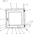
- Fig. 1 shows a window 1 consisting of a fixed frame 2 and a wing 5 pivotable therein both about a vertical axis of rotation 3 and about a horizontal axis of rotation 4.
- the frame 2 and the wing 5 are connected to one another via an upper hinge 6 and a lower hinge 7 ,
- the embodiment provides that the upper hinge 6 is designed as a so-called scissor stay, while the lower hinge 7 is designed as a so-called corner hinge.
- the wing 5 has a locking fitting (not shown here in more detail) which can be operated via a hand lever 8 on the wing 5.
- the locking fitting is designed as a tilt and turn fitting, the possibility for a pivoting movement about the lower horizontal axis of rotation 4 can also be set via the hand lever 8.
- an opening device is attached to the upper horizontal wing spar 9 with a raising arm which is movable perpendicular to the wing plane and connects the upper horizontal wing spar 9 to the upper hinge 6.
- a tilt lock - not visible here - is effective between frame 2 and wing 5, so that the lower horizontal wing edge 11 is held on frame 2.
- the frame spars of the frame 2 and the wing spars of the wing 5 do not run parallel, but have shifted into an antiparallel position due to prolonged use, wear or the like.
- an alignment element 17 is provided on the lower horizontal frame member 16, which with the fold surface 14 of the Wing 5 or a positionally stable component (not shown here) cooperates in such a way that the originally intended spacing of the folding surfaces 14, 13 is restored when the wing 5 is closed.
- the alignment element 17 consists of a casserole which is provided with an ascending slope in the direction of movement and which interacts with the rebate surface 14 of the wing.
- the wing 5 receives its original starting position 12 through the alignment element 17, in which the frame and wing spars are parallel to each other.
- the front wing edge 18 sinks down again as soon as the folded surface 14 slips off the alignment element 17. If the wing 5 is aligned antiparallel so far that the rebate surface 14 no longer meets the run-up slope of the alignment element 17, the wing 5 can only dip into the frame 2 by manually lifting the front wing edge 18.
- Tilt and turn fittings therefore provide that 6 manual adjustment options are attached to the upper hinge, which serve to restore the initial position 12.
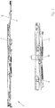
- the in the Fig. 2 Display device 19 shown attached.
- the opening device 19 is part of the turn-tilt fitting and can be brought into various functional positions via the hand lever 8.
- the opening device 19 has a drive rod 20 which is guided below a scissor stay 21.
- An extension arm 22 is guided in a longitudinally displaceable manner in an elongated hole 23 at one end in the scissor stay cover 21 and assigned to the hinge 6 in a manner (not shown here) at the other end 24.
- the deployment arm 22 with a rivet 25 passes through a guide piece 26 such that the guide piece 26 can be moved along the scissor cuff 21 and the deployment arm 22 can be pivoted about the rivet 25.
- the extension arm 22 is also connected to the scissor stay cover 21 via a link 27.
- the extension arm 22 is pivotally connected to the handlebar 27 via the rivet 28.
- the handlebar 27 is in turn pivotally associated with a bolt 29 of a bracket 30.
- the bolt 29 forms the pivot bearing of the handlebar 27 on the scissor stay 21.
- the tab 30 is displaceable along the scissor stay 21 and passes through it in an opening 31.
- An eccentric 32 is arranged between the tab 30 and the scissor cuff 21.
- the eccentric 32 has two diametrically opposite on the peripheral surface 33 Eccentric bellies 34, 35 so that it has an oval cross section.
- the eccentric 32 has a first arm 36 and a second arm 37 which protrude from partially overlapping openings 31, 38 of the scissor cuff 21 and the tab 30.
- the arm 36 protrudes above the scissor cuff 21, while the arm 37 dips below the scissor cuff 21 into a fitting receiving groove of the wing 5 and the drive rod 20 engages in an elongated hole 39.
- the arm 37 strikes an opening edge 40 of the flap 30 that widens like a funnel.
- the arm 36 also forms an indicator for the position of the eccentric 32 that is visible in the installed state of the opening device 19 the handlebar 27 facing away from the bolt 29, then the eccentric 32 is in its minimum setting.
- the eccentric 32 is so acted upon by a first spring element 41 that its eccentric belly 35 would like to step in the direction of the opening edge 42.
- the spring element 41 acts on the arm 37 and produces a corresponding torque on the eccentric 32.
- a second spring element 43 acts on the arm 37, which is relaxed in the neutral position. While the spring element 41 is fixedly assigned to the scissor stay 21 on a bracket 44, the second spring element 43 passes through an abutment 45 fastened to the drive rod 20 with a leg 46 that is guided longitudinally therein.
- the extension arm 22 is coupled at its end 24 to the hinge 6.
- the assignment to the hinge 6 fixed on the frame causes the extension arm 22 to be held in a fixed position by the alignment element 17 when the wing 5 is relatively aligned, while the scissor stay 21 with the wing 5 is relatively stationary in the Fig. 2 is moved to the left.
- the guide piece 26 compensates for this at the free end of the deployment arm 22.
- the handlebar 27 is held rigidly due to its pivotable connection to the extension arm 22, as a result of which the tab 30 is displaced within the opening 31 in the scissor stay cover 21.
- the position of the eccentric 32 and thus the setting of the opening device 19 and the leaf 5 can be reset by adjusting the tilt opening position.
- the wing 5 In the tilt-open position, the wing 5 is fixed on the lower horizontal wing spar 10 on the frame spar 16 and is thus relieved by the alignment element 17.
- the adjustment of the tilt opening position causes the drive rod 20 to be displaced into that in FIG Fig. 4 shown location.
- the abutment 45 guided together with the drive rod 20 leads to a tensioning of the spring element 43. In relation to the first spring element, this is equipped with a higher spring rate so that the force applied by the second spring element 43 exceeds that of the first spring element 41 in the tilted position.
- the spring element 43 exerts a greater torque on the eccentric 32 than the spring element 41, which leads to a rotation of the eccentric 32 counterclockwise in the figure. Since the wing 5 is relieved and aligned via the alignment element, the eccentric 32 takes on its smallest dimension with respect to the opening edges 42, 48.
- the tab 30 is subjected to force in the tilt-open position of the wing 5 in the direction of the swivel mounting of the link 27.
- This is achieved by the arrangement of the tab 30, based on the mounting points of the extension arm 22.
- the extension arm 22, the scissor stay 21 and the link 27 form a triangle, at the corners of which the rivet 25, the rivet 28 and the bolt 29 are arranged.
- the extension arm 22 is spread apart by the scissor stay 21 as a result of the opening movement of the wing 5, so that the link 27 is subjected to tension and the tab 30 is subjected to force in the direction of the rivet 28.
- the eccentric 32 variably fixes the tab 30 in different positions relative to the scissor stay 21.
- the effective length 49 of the opening device 19 results accordingly from the position of a coupling device 50 for a hinge part, which is additionally provided with a manual adjusting device 51 and the position of the bolt 29.
- the hinge 7, the opening arm 22 and the handlebar 27 and the scissor cuff 21 existing support structure can thus be adjusted in length 49 by the tab 30 determining the position of the link 27 on the scissor cuff 21 and the eccentric 32 which spreads between the tab 30 and scissor cuff 21.
- tangential surface sections can be provided on the eccentric bellies 34, 35.
Description
Die Erfindung betrifft eine Beschlaganordnung nach dem Oberbegriff des Anspruchs 1.The invention relates to a fitting arrangement according to the preamble of
Die
Aus der
Aus der
Nachteilig dabei ist es, dass die Anordnung der Kopplungsmittel eine rechte und linke Verwendbarkeit der Ausstellvorrichtung nicht ermöglichen, zumindest aber den vorhandenen Bauraum durch die Anordnung am Scherenlenker einschränken.The disadvantage here is that the arrangement of the coupling means does not allow the right and left usability of the opening device, but at least limits the available space by the arrangement on the scissor arm.
Der Erfindung liegt daher die Aufgabe zugrunde, eine einfache Rückstellung zu ermöglichen, die idealerweise zyklisch bei normaler Nutzung des Fensters oder der Tür erfolgt und die eine universelle Nutzung der Beschlaganordnung ermöglicht.The invention is therefore based on the object of enabling a simple reset, which ideally takes place cyclically with normal use of the window or the door and which enables universal use of the fitting arrangement.
Zur Lösung dieser Aufgabe sieht die Erfindung bei einem gattungsgemäßen Beschlag vor, dass ein erstes der relativ zueinander verschiebbaren Teile der Scherenstulp ist, und das andere der genannten Teile der Lenker ist, wobei zwischen Scherenstulp und Lenker eine relativ zum Scherenstulp verstellbare Lasche vorgesehen ist, welche die Schwenklagerung des Lenkers aufweist und die einen Exzenter lagert, der zwischen dem Scherenstulp und der Schwenklagerung wirksam ist, wobei der Exzenter durch ein erstes Federelement spreizend kraftbeaufschlagt ist.To achieve this object, the invention provides in a generic fitting that a first of the relatively displaceable parts of the scissor stay and the other of the parts mentioned is the handlebar, whereby between the scissor stay and handlebar is provided an adjustable tab relative to the scissor stay stay, which has the pivot bearing of the handlebar and supports an eccentric, which is effective between the scissor stay and the pivot bearing, the eccentric being acted upon by a first spring element.
Der Erfindung gelingt es dadurch, eine universelle Anwendbarkeit zu gewährleisten, die praktisch vollständig im Bereich des Scherenstulps oder darunter angeordnet werden kann und damit keinen Falzraum beansprucht.The invention thereby succeeds in ensuring universal applicability, which can be arranged practically completely in the area of the scissor stay or below and thus does not require any rebate space.
Das erste Federelement hat ein Widerlager am Scherenstulp und das zweite Federelement ist mit einer Treibstange gekoppelt, die unterhalb des Scherenstulps geführt ist und ein Widerlager hierzu trägt. Dadurch kann die Wirkung des Exzenters über den Treibstangenbeschlag gesteuert werden.The first spring element has an abutment on the scissor cuff and the second spring element is coupled to a drive rod which is guided below the scissor cuff and carries an abutment for this. The effect of the eccentric can thus be controlled via the connecting rod fitting.
Um die Wirkung des Exzenters bei geringen Abmessungen zu maximieren ist vorgesehen, dass der Exzenter durch zwei sich diametral an der Umfangsfläche gegenüberliegenden Exzenterbäuchen einen ovalen Querschnitt erhält.In order to maximize the effect of the eccentric with small dimensions, it is provided that the eccentric is given an oval cross section by two eccentric bellies diametrically opposite one another on the peripheral surface.
Um den Flügel mit der Beschlaganordnung in der Schwenköffnungsstellung in der gewünschten Ausrichtlage zu fixieren ist vorgesehen, dass in der Schwenkbereitschaftsstellung der Treibstange das erste Federelement bei entspanntem zweiten Federelement gespannt ist.In order to fix the sash with the fitting arrangement in the swivel opening position in the desired alignment position, it is provided that the first spring element is tensioned when the second spring element is relaxed in the swivel ready position of the drive rod.
Die Neuausrichtung der Beschlaganordnung wird dadurch erreicht, dass in der Kippbereitschaftsstellung das zweite Federelement über die Treibstange gespannt wird, was eine Rückstellung des Exzenters zur Folge hat.The reorientation of the fitting arrangement is achieved in that the second spring element is stretched over the drive rod in the readiness for tilting, which results in a resetting of the eccentric.
Um eine zuverlässige Rückstellung des Exzenters zu erreichen ist vorgesehen, dass die Lasche in der Kippöffnungsstellung des Flügels in Richtung der Schwenklagerung des Lenkers kraftbeaufschlagt wird, so dass der Exzenter kräftefrei durch die Federelemente bewegt werden kann.In order to achieve a reliable resetting of the eccentric, it is provided that the flap is subjected to force in the tilt-open position of the wing in the direction of the pivoting mounting of the handlebar, so that the eccentric can be moved by the spring elements without force.
Die notwendige Relativausrichtung von Flügel und Rahmen wird auf einfache Weise erreicht, wenn die Ausstellvorrichtung an einem Flügel angeordnet ist, der zumindest in seiner Schwenkstellung in und nahe einer flächenparallelen Ausrichtung des Flügels zu einem feststehenden Rahmen über ein Ausrichtelement in eine Sollposition relativ zum Rahmen gebracht wird.The necessary relative alignment of sash and frame is achieved in a simple manner if the opening device is arranged on a sash, which is brought into a desired position relative to the frame at least in its pivoting position in and near a surface-parallel alignment of the sash to a fixed frame via an alignment element ,
Weitere vorteilhafte Ausgestaltungen ergeben sich aus den Zeichnungen. Es zeigt:
- Fig. 1
- eine schematische Skizze eines Fensters oder einer Tür,
- Fig. 2
- eine Ausstellvorrichtung in einer Neutralstellung, in der der Flügel relativ zum Rahmen ausgerichtet wird, in einer Übersicht und einer vergrößerten Detailansicht,
- Fig. 3
- die Ausstellvorrichtung in den Ansichten nach
Figur 2 - Fig. 4
- die Ausstellvorrichtung in den Ansichten nach
Figur 23 in einer Kippbereitschaftsstellung des Treibstangenbeschlages.
- Fig. 1
- a schematic sketch of a window or a door,
- Fig. 2
- an opening device in a neutral position, in which the sash is aligned relative to the frame, in an overview and an enlarged detail view,
- Fig. 3
- the opening device in the views
Figure 2 in a fixed adjustment position and - Fig. 4
- the opening device in the views
Figure 2 and3 in a tilt-ready position of the drive rod fitting.
Die Ausgestaltung sieht dabei vor, dass das obere Scharnier 6 als sogenanntes Scherenlager ausgestaltet ist, während das untere Scharnier 7 als sogenanntes Ecklager ausgeführt ist. Der Flügel 5 weist zur Verriegelung in dem Rahmen 2 einen - hier nicht näher dargestellten - Verriegelungsbeschlag auf, der über einen Handhebel 8 am Flügel 5 bedient werden kann. Bei einer Ausführung des Verriegelungsbeschlags als Drehkippbeschlag ist über den Handhebel 8 auch die Möglichkeit für eine Schwenkbewegung um die untere horizontale Drehachse 4 einstellbar. An dem oberen waagerechten Flügelholm 9 ist in diesem Fall eine Ausstellvorrichtung mit einem senkrecht zur Flügelebene beweglichen Ausstellarm befestigt, der den oberen waagerechten Flügelholm 9 mit dem oberen Scharnier 6 verbindet. Am unteren waagerechten Flügelholm 10 ist dabei zwischen Rahmen 2 und Flügel 5 eine - hier nicht sichtbare - Kippverriegelung wirksam, so dass die untere waagerechte Flügelkante 11 am Rahmen 2 gehalten ist. Im dargestellten Ausführungsbeispiel ist angedeutet, dass die Rahmenholme des Rahmens 2 und die Flügelholme des Flügels 5 nicht parallel verlaufen, sondern sich durch längere Benutzung, Verschleiß od. dgl. in eine antiparallele Lage verschoben haben. Dadurch ist ein zwischen dem Flügel 5 und dem Rahmen 2 in
der - angedeuteten - Ausgangslage 12 bestehender Abstand der Falzflächen 13, 14 - die sogenannte Falzluft oder das Kammermaß 15 - in einzelnen Bereichen auf ein Minimum reduziert. Daher kommt es beim Schließen des Flügels 5 beispielsweise aus der Drehstellung zum Klemmen. Daher wird beispielsweise am unteren waagerechten Rahmenholm 16 ein Ausrichtelement 17 vorgesehen, das mit der Falzfläche 14 des Flügels 5 oder einem - hier nicht dargestellten - lagefesten Bauteil derart zusammenwirkt, dass der ursprünglich beabsichtigte Abstand der Falzflächen 14, 13 sich beim Schließen des Flügels 5 wieder einstellt. Das Ausrichtelement 17 besteht dabei im einfachsten Fall aus einem mit einer in Bewegungsrichtung aufsteigenden Auflaufschräge ausgestatteten Auflauf, welcher mit der Falzfläche 14 des Flügels zusammenwirkt. Der Flügel 5 erhält durch das Ausrichtelement 17 seine ursprüngliche Ausgangslage 12, bei der die Rahmen- und Flügelholme parallel zueinander liegen. Beim Öffnen des Flügels 5 jedoch sackt die vordere Flügelkante 18 wieder nach unten, sobald die Falzfläche 14 von dem Ausrichtelement 17 abrutscht. Ist der Flügel 5 soweit antiparallel ausgerichtet, dass die Falzfläche 14 nicht mehr die Auflaufschräge des Ausrichtelementes 17 trifft, kann der Flügel 5 nur noch durch manuelles Anheben der vorderen Flügelkante 18 in den Rahmen 2 eintauchen.The embodiment provides that the
the - indicated -
Drehkippbeschläge sehen daher vor, dass an dem oberen Scharnier 6 manuelle Verstellmöglichkeiten angebracht sind, die zum Wiederherstellen der Ausgangslage 12 dienen.Tilt and turn fittings therefore provide that 6 manual adjustment options are attached to the upper hinge, which serve to restore the
Im dargestellten Ausführungsbeispiel ist an dem oberen waagerechten Flügelholm 9 die in
Zwischen der Lasche 30 und dem Scherenstulp 21 ist ein Exzenter 32 angeordnet. Der Exzenter 32 weist zwei sich diametral an der Umfangsfläche 33 gegenüberliegende Exzenterbäuche 34, 35 auf, so dass dieser einen ovalen Querschnitt erhält. Zudem hat der Exzenter 32 einen ersten Arm 36 und einen zweiten Arm 37, die aus sich teilweise überdeckenden Öffnungen 31, 38 des Scherenstulps 21 und der Lasche 30 vorragen. Der Arm 36 ragt über den Scherenstulp 21 vor, während der Arm 37 unterhalb des Scherenstulps 21 in eine Beschlagaufnahmenut des Flügels 5 eintaucht und die Treibstange 20 in einem Langloch 39 durchgreift. In der dargestellten Neutralstellung des Exzenters 32 schlägt der Arm 37 an einen sich trichterartig erweiternden Öffnungsrand 40 der Lasche 30. Der Arm 36 bildet zudem einen im eingebauten Zustand der Ausstellvorrichtung 19 sichtbaren Anzeiger für die Stellung des Exzenters 32. Ist der Arm 36 von der Schwenklagerung des Lenkers 27 durch den Bolzen 29 abgewandt, dann befindet sich der Exzenter 32 in seiner Minimaleinstellung.An eccentric 32 is arranged between the
Der Exzenter 32 ist durch ein erstes Federelement 41 so kraftbeaufschlagt, dass dessen Exzenterbauch 35 in Richtung des Öffnungsrandes 42 treten möchte. Dazu greift das Federelement 41 an dem Arm 37 an und bewirkt ein entsprechendes Drehmoment am Exzenter 32. Am Arm 37 greift ein zweites Federelement 43 an, welches in der Neutralstellung entspannt ist. Während das Federelement 41 ortsfest dem Scherenstulp 21 an einem Bock 44 zugeordnet ist, durchgreift das zweite Federelement 43 einen an der Treibstange 20 befestigtes Widerlager 45 mit einem darin längsgeführten Schenkel 46.The eccentric 32 is so acted upon by a
Aufgrund der vorbeschrieben Anordnung ergibt sich nachfolgende Wirkungsweise. In der in
Es ergibt sich dadurch, die in der
Damit die Justierung immer wieder neu vorgenommen wird ist vorgesehen, dass die Lage des Exzenters 32 und damit die Einstellung der Ausstellvorrichtung 19 und des Flügels 5 durch Einstellen der Kippöffnungsstellung zurückgesetzt werden kann. In der Kippöffnungsstellung ist der Flügel 5 am unteren waagerechten Flügelholm 10 am Rahmenholm 16 festgelegt und damit durch das Ausrichtelement 17 entlastet. Das Einstellen der Kippöffnungsstellung bewirkt eine Verschiebung der Treibstange 20 in die in der
Dabei ist es von Vorteil, dass die Lasche 30 in der Kippöffnungsstellung des Flügels 5 in Richtung der Schwenklagerung des Lenkers 27 kraftbeaufschlagt wird. Dies wird durch die Anordnung der Lasche 30, bezogen auf die Lagerungspunkte des Ausstellarms 22, erreicht. In der Kippöffnungsstellung bilden der Ausstellarm 22, der Scherenstulp 21 und der Lenker 27 ein Dreieck, an dessen Ecken der Niet 25, der Niet 28 und der Bolzen 29 angeordnet sind. Der Ausstellarm 22 wird infolge der Ausstellbewegung des Flügels 5 von dem Scherenstulp 21 abgespreizt, so dass der Lenker 27 auf Zug beansprucht wird und die Lasche 30 in Richtung auf den Niet 28 kraftbeaufschlagt. Infolge der ausschließlich längsverschieblichen Lagerung der Lasche 30 im Scherenstulp 21 wird die Lasche 30 in Längsrichtung des Scherenstulps 21 vom Öffnungsrand 42 weggezogen, so dass der Exzenter 32 druckfrei wird. Die Entlastung des Exzenters 32 bewirkt, dass das Federelement 43 eine Verdrehung des Exzenters 32 bewirken kann.It is advantageous that the
Wird ausgehend von der Kippstellung der Treibstangenbeschlag/ die Treibstange 20 in die Drehöffnungsstellung gebracht, rückt das Widerlager 45 in die in
Der Exzenter 32 legt die Lasche 30 relativ zu dem Scherenstulp 21 variabel in verschiedenen Stellungen fest. Die wirksame Länge 49 der Ausstellvorrichtung 19 ergibt sich dem entsprechend aus der Lage einer Kupplungsvorrichtung 50 für ein Scharnierteil, welches zusätzlich mit einer manuellen Stellvorrichtung 51 versehen ist und der Lage des Bolzens 29. Die aus dem Scharnier 7, dem Ausstellarm 22 und dem Lenker 27 sowie dem Scherenstulp 21 bestehende Tragstruktur ist also in der Länge 49 durch den die Lage des Lenkers 27 am Scherenstulp 21 bestimmende Lasche 30 und den zwischen Lasche 30 und Scherenstulp 21 spreizend wirkenden Exzenter 32 einstellbar.The eccentric 32 variably fixes the
Zeigt der Arm 36 an, dass der maximal erreichbare Stellweg des Exzenters 32 erreicht ist, kann über die Stellvorrichtung 51 eine neue Grundeinstellung herbeigeführt werden, die nachfolgend durch die getroffene Anordnung funktionsfähig gehalten wird.If the
Um ein unerwünschtes Rückstellen des Exzenters 32 zu verhindern, können an den Exzenterbäuchen 34, 35 tangentiale Flächenabschnitte vorgesehen werden.In order to prevent undesired resetting of the eccentric 32, tangential surface sections can be provided on the
- 11
- Fensterwindow
- 22
- Rahmenframe
- 33
- Drehachseaxis of rotation
- 44
- Drehachseaxis of rotation
- 55
- Flügelwing
- 66
- Scharnierhinge
- 77
- Scharnierhinge
- 88th
- Handhebelhand lever
- 99
- oberer waagerechter Flügelholmupper horizontal wing spar
- 1010
- unterer waagerechter Flügelholmlower horizontal wing spar
- 1111
- Flügelkantewing edge
- 1212
- Ausgangslagestarting position
- 1313
- Falzflächerebate surface
- 1414
- Falzflächerebate surface
- 1515
- KammermaßChamber dimension
- 1616
- Rahmenholmframe spar
- 1717
- Ausrichtelementaligning
- 1818
- Flügelkantewing edge
- 1919
- AusstellvorrichtungA stay mechanism
- 2020
- Treibstangedriving rod
- 2121
- ScherenstulpStay guide
- 2222
- Ausstellarmout arm
- 2323
- LanglochLong hole
- 2424
- EndeThe End
- 2525
- Nietrivet
- 2626
- Führungsstückguide piece
- 2727
- Lenkerhandlebars
- 2828
- Nietrivet
- 2929
- Bolzenbolt
- 3030
- Lascheflap
- 3131
- Öffnungopening
- 3232
- Exzentereccentric
- 3333
- Umfangsflächeperipheral surface
- 3434
- ExzenterbauchExzenterbauch
- 3535
- ExzenterbauchExzenterbauch
- 3636
- Armpoor
- 3737
- Armpoor
- 3838
- Öffnungopening
- 3939
- LanglochLong hole
- 4040
- Öffnungsrandopening edge
- 4141
- Federelementspring element
- 4242
- Öffnungsrandopening edge
- 4343
- Federelementspring element
- 4444
- Bockbuck
- 4545
- Widerlagerabutment
- 4646
- Schenkelleg
- 4747
- Abstanddistance
- 4848
- Öffnungsrandopening edge
- 4949
- Längelength
- 5050
- Kupplungsvorrichtungcoupling device
- 5151
- Stellvorrichtunglocking device
Claims (2)
- Fitting assembly for a rotating-tilting window or door, with an opening device (19) which comprises an opening arm (22) and a link (27) pivotably connected to the opening arm (22), wherein the link (27) can be coupled to a wing (5) of the window or of the door at a scissor plate (21) at a first coupling point, and wherein the opening arm (22) at a second coupling device (50) can be coupled to a scissor bearing, which can be fastened to the main frame of the window or of the door, in order to pivotably support the wing (5) on the main frame (2), wherein two parts of the supporting structure, which comprises the opening device (19) and the scissor bearing, can be fixed relative to each other in a variable manner in different positions in order to adjust the effective length (49) of the opening device (19), and wherein the two parts are connected to each other by means of at least one adjustable coupling element (32), wherein one of the said parts is the scissor plate (21), and the other of the said parts is the link (27), wherein a plate (30) that can be adjusted relative to the scissor plate (21) is provided between the scissor plate (21) and link (27), which plate (30) has the pivot bearing of the link (27) and supports the eccentric element (32) which acts between the scissor plate (21) and the pivot bearing,
characterized in that
the eccentric element is configured such that, at the closing of the wing (5), it is automatically adjusted in such a way that an incorrect setting of the wing (5) due to a change in the effective length (49) of the opening device (19) will be corrected,
that the eccentric element (32) is subjected to force in a spreading manner by a first spring element (41),
that the first spring element (41) has a counter-bearing (44) at the scissor plate (21), and the second spring element (43) is coupled to a drive rod (20), which is guided beneath the scissor plate (21) and carries a counter-bearing (45) for this purpose,
that, by means of two eccentric cambers (34, 35) diametrically opposed on the circumferential surface (33), the eccentric element (32) is provided with an eccentric cross-section, such that, in the position of the drive rod (20) prepared for pivoting, the first spring element (41) remains tensioned with the second spring element (43) relaxed,
that in the position prepared for tilting the second spring element (43) is tensioned by means of the drive rod (20),
and that the plate (30), in the tilt open position of the wing, is subjected to force in the direction of the pivot bearing of the link (27). - Fitting assembly according to claim 1,
characterized in that
the opening device (19) is arranged at a wing (5), which, at least in its pivot position, is brought into and close to a surface-parallel alignment of the wing (5) at a fixed frame (2), by means of an alignment element (17), into a reference position relative to the frame (2).
Priority Applications (1)
| Application Number | Priority Date | Filing Date | Title |
|---|---|---|---|
| PL17712764T PL3440295T3 (en) | 2016-04-07 | 2017-03-22 | Hinge fitting with a check for tilt and turn windows |
Applications Claiming Priority (2)
| Application Number | Priority Date | Filing Date | Title |
|---|---|---|---|
| DE202016002166.5U DE202016002166U1 (en) | 2016-04-07 | 2016-04-07 | fitting assembly |
| PCT/EP2017/056752 WO2017174352A1 (en) | 2016-04-07 | 2017-03-22 | Fitting assembly having an opening device for tilt-and-turn windows |
Publications (2)
| Publication Number | Publication Date |
|---|---|
| EP3440295A1 EP3440295A1 (en) | 2019-02-13 |
| EP3440295B1 true EP3440295B1 (en) | 2020-02-12 |
Family
ID=58398181
Family Applications (1)
| Application Number | Title | Priority Date | Filing Date |
|---|---|---|---|
| EP17712764.4A Active EP3440295B1 (en) | 2016-04-07 | 2017-03-22 | Hinge fitting with a check for tilt and turn windows |
Country Status (5)
| Country | Link |
|---|---|
| EP (1) | EP3440295B1 (en) |
| DE (1) | DE202016002166U1 (en) |
| PL (1) | PL3440295T3 (en) |
| RU (1) | RU2752873C2 (en) |
| WO (1) | WO2017174352A1 (en) |
Cited By (1)
| Publication number | Priority date | Publication date | Assignee | Title |
|---|---|---|---|---|
| DE202023100930U1 (en) | 2023-02-28 | 2023-03-08 | Siegenia-Aubi Kg | fitting arrangement |
Family Cites Families (4)
| Publication number | Priority date | Publication date | Assignee | Title |
|---|---|---|---|---|
| DE2201603B2 (en) * | 1972-01-14 | 1980-04-03 | Fa. August Bilstein, 5828 Ennepetal | Opening device for tilt and swivel sashes of windows or doors |
| DE19718325C1 (en) | 1997-04-30 | 1998-08-13 | Siegenia Frank Kg | Adjuster for aligning door and window hinge |
| DE102014101218A1 (en) | 2014-01-31 | 2015-08-06 | Maco Technologie Gmbh | fitting assembly |
| DE102014112897A1 (en) * | 2014-09-08 | 2016-03-10 | Maco Technologie Gmbh | fitting assembly |
-
2016
- 2016-04-07 DE DE202016002166.5U patent/DE202016002166U1/en active Active
-
2017
- 2017-03-22 RU RU2018134328A patent/RU2752873C2/en active
- 2017-03-22 EP EP17712764.4A patent/EP3440295B1/en active Active
- 2017-03-22 PL PL17712764T patent/PL3440295T3/en unknown
- 2017-03-22 WO PCT/EP2017/056752 patent/WO2017174352A1/en active Application Filing
Non-Patent Citations (1)
| Title |
|---|
| None * |
Cited By (1)
| Publication number | Priority date | Publication date | Assignee | Title |
|---|---|---|---|---|
| DE202023100930U1 (en) | 2023-02-28 | 2023-03-08 | Siegenia-Aubi Kg | fitting arrangement |
Also Published As
| Publication number | Publication date |
|---|---|
| EP3440295A1 (en) | 2019-02-13 |
| RU2752873C2 (en) | 2021-08-11 |
| DE202016002166U1 (en) | 2017-07-10 |
| WO2017174352A1 (en) | 2017-10-12 |
| RU2018134328A (en) | 2020-04-01 |
| PL3440295T3 (en) | 2020-07-13 |
| RU2018134328A3 (en) | 2020-05-27 |
Similar Documents
| Publication | Publication Date | Title |
|---|---|---|
| EP3198097B1 (en) | Furniture hinge | |
| EP0736659B1 (en) | Device for pivotably supporting a wing | |
| EP2828460B1 (en) | Fitting for a window or door with a wing moveable into a parallel plane and horizontally slidable in said parallel plane | |
| EP0515931B2 (en) | Fitting for pivoting and tiltable wings | |
| EP1837472A1 (en) | Window, door or similar with a load alleviation device | |
| DE3041399C3 (en) | Tilt & Turn hardware for windows or the like. | |
| DE3738596A1 (en) | HIDDEN IN FOLDING FITTING FOR SWIVEL BEARINGS, IN PART. TILTING SWIVEL BEARING, FOR WING OF WINDOWS, DOORS OR THE LIKE | |
| DE3843680C2 (en) | Concealed fitting for swivel bearings of doors, windows or the like | |
| EP3440295B1 (en) | Hinge fitting with a check for tilt and turn windows | |
| EP0276678B1 (en) | Fitting for an at least pivoting door, window or the like | |
| EP3045634B1 (en) | Checking device for a window or a door comprising an energy storage device | |
| DE1810671A1 (en) | Adjusting device on windows, doors or the like. | |
| DE2940049C2 (en) | Opening device for tilt and swivel sashes of windows or doors | |
| DE202007011982U1 (en) | Adjustable band | |
| WO2017148663A1 (en) | Window or door | |
| DE2443036C3 (en) | Opening device | |
| EP1117888A1 (en) | Device for providing gap ventilation | |
| DE975218C (en) | Turn-tilt fittings, especially for large windows and doors | |
| DE1708443A1 (en) | Fitting for tilt and swivel sash of windows | |
| DE102005026756A1 (en) | Drehflügelbegrenzer | |
| DE2932865A1 (en) | Roof window wing fitting - has torsion spring assembly connected to one frame and force locked to other | |
| EP2944750A1 (en) | Protection against excess rotation of a folding sliding shutter | |
| WO2004063507A1 (en) | Mounting unit for a window or a door | |
| DE1213290B (en) | Fitting for window sash | |
| DE10228604B3 (en) | Fitting for a window or a door |
Legal Events
| Date | Code | Title | Description |
|---|---|---|---|
| STAA | Information on the status of an ep patent application or granted ep patent |
Free format text: STATUS: UNKNOWN |
|
| STAA | Information on the status of an ep patent application or granted ep patent |
Free format text: STATUS: THE INTERNATIONAL PUBLICATION HAS BEEN MADE |
|
| PUAI | Public reference made under article 153(3) epc to a published international application that has entered the european phase |
Free format text: ORIGINAL CODE: 0009012 |
|
| STAA | Information on the status of an ep patent application or granted ep patent |
Free format text: STATUS: REQUEST FOR EXAMINATION WAS MADE |
|
| 17P | Request for examination filed |
Effective date: 20180919 |
|
| AK | Designated contracting states |
Kind code of ref document: A1 Designated state(s): AL AT BE BG CH CY CZ DE DK EE ES FI FR GB GR HR HU IE IS IT LI LT LU LV MC MK MT NL NO PL PT RO RS SE SI SK SM TR |
|
| AX | Request for extension of the european patent |
Extension state: BA ME |
|
| DAV | Request for validation of the european patent (deleted) | ||
| DAX | Request for extension of the european patent (deleted) | ||
| GRAP | Despatch of communication of intention to grant a patent |
Free format text: ORIGINAL CODE: EPIDOSNIGR1 |
|
| STAA | Information on the status of an ep patent application or granted ep patent |
Free format text: STATUS: GRANT OF PATENT IS INTENDED |
|
| INTG | Intention to grant announced |
Effective date: 20191106 |
|
| GRAS | Grant fee paid |
Free format text: ORIGINAL CODE: EPIDOSNIGR3 |
|
| GRAA | (expected) grant |
Free format text: ORIGINAL CODE: 0009210 |
|
| STAA | Information on the status of an ep patent application or granted ep patent |
Free format text: STATUS: THE PATENT HAS BEEN GRANTED |
|
| AK | Designated contracting states |
Kind code of ref document: B1 Designated state(s): AL AT BE BG CH CY CZ DE DK EE ES FI FR GB GR HR HU IE IS IT LI LT LU LV MC MK MT NL NO PL PT RO RS SE SI SK SM TR |
|
| REG | Reference to a national code |
Ref country code: GB Ref legal event code: FG4D Free format text: NOT ENGLISH |
|
| REG | Reference to a national code |
Ref country code: CH Ref legal event code: EP |
|
| REG | Reference to a national code |
Ref country code: AT Ref legal event code: REF Ref document number: 1232314 Country of ref document: AT Kind code of ref document: T Effective date: 20200215 |
|
| REG | Reference to a national code |
Ref country code: IE Ref legal event code: FG4D Free format text: LANGUAGE OF EP DOCUMENT: GERMAN |
|
| REG | Reference to a national code |
Ref country code: DE Ref legal event code: R096 Ref document number: 502017003785 Country of ref document: DE |
|
| PG25 | Lapsed in a contracting state [announced via postgrant information from national office to epo] |
Ref country code: RS Free format text: LAPSE BECAUSE OF FAILURE TO SUBMIT A TRANSLATION OF THE DESCRIPTION OR TO PAY THE FEE WITHIN THE PRESCRIBED TIME-LIMIT Effective date: 20200212 Ref country code: FI Free format text: LAPSE BECAUSE OF FAILURE TO SUBMIT A TRANSLATION OF THE DESCRIPTION OR TO PAY THE FEE WITHIN THE PRESCRIBED TIME-LIMIT Effective date: 20200212 Ref country code: NO Free format text: LAPSE BECAUSE OF FAILURE TO SUBMIT A TRANSLATION OF THE DESCRIPTION OR TO PAY THE FEE WITHIN THE PRESCRIBED TIME-LIMIT Effective date: 20200512 |
|
| REG | Reference to a national code |
Ref country code: LT Ref legal event code: MG4D |
|
| REG | Reference to a national code |
Ref country code: NL Ref legal event code: MP Effective date: 20200212 |
|
| PG25 | Lapsed in a contracting state [announced via postgrant information from national office to epo] |
Ref country code: IS Free format text: LAPSE BECAUSE OF FAILURE TO SUBMIT A TRANSLATION OF THE DESCRIPTION OR TO PAY THE FEE WITHIN THE PRESCRIBED TIME-LIMIT Effective date: 20200612 Ref country code: BG Free format text: LAPSE BECAUSE OF FAILURE TO SUBMIT A TRANSLATION OF THE DESCRIPTION OR TO PAY THE FEE WITHIN THE PRESCRIBED TIME-LIMIT Effective date: 20200512 Ref country code: HR Free format text: LAPSE BECAUSE OF FAILURE TO SUBMIT A TRANSLATION OF THE DESCRIPTION OR TO PAY THE FEE WITHIN THE PRESCRIBED TIME-LIMIT Effective date: 20200212 Ref country code: SE Free format text: LAPSE BECAUSE OF FAILURE TO SUBMIT A TRANSLATION OF THE DESCRIPTION OR TO PAY THE FEE WITHIN THE PRESCRIBED TIME-LIMIT Effective date: 20200212 Ref country code: LV Free format text: LAPSE BECAUSE OF FAILURE TO SUBMIT A TRANSLATION OF THE DESCRIPTION OR TO PAY THE FEE WITHIN THE PRESCRIBED TIME-LIMIT Effective date: 20200212 Ref country code: GR Free format text: LAPSE BECAUSE OF FAILURE TO SUBMIT A TRANSLATION OF THE DESCRIPTION OR TO PAY THE FEE WITHIN THE PRESCRIBED TIME-LIMIT Effective date: 20200513 |
|
| PG25 | Lapsed in a contracting state [announced via postgrant information from national office to epo] |
Ref country code: NL Free format text: LAPSE BECAUSE OF FAILURE TO SUBMIT A TRANSLATION OF THE DESCRIPTION OR TO PAY THE FEE WITHIN THE PRESCRIBED TIME-LIMIT Effective date: 20200212 |
|
| PG25 | Lapsed in a contracting state [announced via postgrant information from national office to epo] |
Ref country code: LT Free format text: LAPSE BECAUSE OF FAILURE TO SUBMIT A TRANSLATION OF THE DESCRIPTION OR TO PAY THE FEE WITHIN THE PRESCRIBED TIME-LIMIT Effective date: 20200212 Ref country code: DK Free format text: LAPSE BECAUSE OF FAILURE TO SUBMIT A TRANSLATION OF THE DESCRIPTION OR TO PAY THE FEE WITHIN THE PRESCRIBED TIME-LIMIT Effective date: 20200212 Ref country code: PT Free format text: LAPSE BECAUSE OF FAILURE TO SUBMIT A TRANSLATION OF THE DESCRIPTION OR TO PAY THE FEE WITHIN THE PRESCRIBED TIME-LIMIT Effective date: 20200705 Ref country code: EE Free format text: LAPSE BECAUSE OF FAILURE TO SUBMIT A TRANSLATION OF THE DESCRIPTION OR TO PAY THE FEE WITHIN THE PRESCRIBED TIME-LIMIT Effective date: 20200212 Ref country code: SM Free format text: LAPSE BECAUSE OF FAILURE TO SUBMIT A TRANSLATION OF THE DESCRIPTION OR TO PAY THE FEE WITHIN THE PRESCRIBED TIME-LIMIT Effective date: 20200212 Ref country code: SK Free format text: LAPSE BECAUSE OF FAILURE TO SUBMIT A TRANSLATION OF THE DESCRIPTION OR TO PAY THE FEE WITHIN THE PRESCRIBED TIME-LIMIT Effective date: 20200212 Ref country code: ES Free format text: LAPSE BECAUSE OF FAILURE TO SUBMIT A TRANSLATION OF THE DESCRIPTION OR TO PAY THE FEE WITHIN THE PRESCRIBED TIME-LIMIT Effective date: 20200212 Ref country code: RO Free format text: LAPSE BECAUSE OF FAILURE TO SUBMIT A TRANSLATION OF THE DESCRIPTION OR TO PAY THE FEE WITHIN THE PRESCRIBED TIME-LIMIT Effective date: 20200212 Ref country code: CZ Free format text: LAPSE BECAUSE OF FAILURE TO SUBMIT A TRANSLATION OF THE DESCRIPTION OR TO PAY THE FEE WITHIN THE PRESCRIBED TIME-LIMIT Effective date: 20200212 |
|
| REG | Reference to a national code |
Ref country code: DE Ref legal event code: R097 Ref document number: 502017003785 Country of ref document: DE |
|
| PG25 | Lapsed in a contracting state [announced via postgrant information from national office to epo] |
Ref country code: MC Free format text: LAPSE BECAUSE OF FAILURE TO SUBMIT A TRANSLATION OF THE DESCRIPTION OR TO PAY THE FEE WITHIN THE PRESCRIBED TIME-LIMIT Effective date: 20200212 |
|
| PLBE | No opposition filed within time limit |
Free format text: ORIGINAL CODE: 0009261 |
|
| STAA | Information on the status of an ep patent application or granted ep patent |
Free format text: STATUS: NO OPPOSITION FILED WITHIN TIME LIMIT |
|
| PG25 | Lapsed in a contracting state [announced via postgrant information from national office to epo] |
Ref country code: LU Free format text: LAPSE BECAUSE OF NON-PAYMENT OF DUE FEES Effective date: 20200322 |
|
| 26N | No opposition filed |
Effective date: 20201113 |
|
| PG25 | Lapsed in a contracting state [announced via postgrant information from national office to epo] |
Ref country code: IE Free format text: LAPSE BECAUSE OF NON-PAYMENT OF DUE FEES Effective date: 20200322 |
|
| PG25 | Lapsed in a contracting state [announced via postgrant information from national office to epo] |
Ref country code: SI Free format text: LAPSE BECAUSE OF FAILURE TO SUBMIT A TRANSLATION OF THE DESCRIPTION OR TO PAY THE FEE WITHIN THE PRESCRIBED TIME-LIMIT Effective date: 20200212 |
|
| PG25 | Lapsed in a contracting state [announced via postgrant information from national office to epo] |
Ref country code: MT Free format text: LAPSE BECAUSE OF FAILURE TO SUBMIT A TRANSLATION OF THE DESCRIPTION OR TO PAY THE FEE WITHIN THE PRESCRIBED TIME-LIMIT Effective date: 20200212 Ref country code: CY Free format text: LAPSE BECAUSE OF FAILURE TO SUBMIT A TRANSLATION OF THE DESCRIPTION OR TO PAY THE FEE WITHIN THE PRESCRIBED TIME-LIMIT Effective date: 20200212 |
|
| PG25 | Lapsed in a contracting state [announced via postgrant information from national office to epo] |
Ref country code: MK Free format text: LAPSE BECAUSE OF FAILURE TO SUBMIT A TRANSLATION OF THE DESCRIPTION OR TO PAY THE FEE WITHIN THE PRESCRIBED TIME-LIMIT Effective date: 20200212 Ref country code: AL Free format text: LAPSE BECAUSE OF FAILURE TO SUBMIT A TRANSLATION OF THE DESCRIPTION OR TO PAY THE FEE WITHIN THE PRESCRIBED TIME-LIMIT Effective date: 20200212 |
|
| PGFP | Annual fee paid to national office [announced via postgrant information from national office to epo] |
Ref country code: FR Payment date: 20230322 Year of fee payment: 7 Ref country code: AT Payment date: 20230322 Year of fee payment: 7 |
|
| PGFP | Annual fee paid to national office [announced via postgrant information from national office to epo] |
Ref country code: TR Payment date: 20230316 Year of fee payment: 7 Ref country code: PL Payment date: 20230224 Year of fee payment: 7 Ref country code: GB Payment date: 20230322 Year of fee payment: 7 Ref country code: DE Payment date: 20230323 Year of fee payment: 7 Ref country code: BE Payment date: 20230322 Year of fee payment: 7 |
|
| PGFP | Annual fee paid to national office [announced via postgrant information from national office to epo] |
Ref country code: IT Payment date: 20230331 Year of fee payment: 7 Ref country code: CH Payment date: 20230401 Year of fee payment: 7 |