EP3439957B1 - Contoured class divider - Google Patents
Contoured class divider Download PDFInfo
- Publication number
- EP3439957B1 EP3439957B1 EP16724239.5A EP16724239A EP3439957B1 EP 3439957 B1 EP3439957 B1 EP 3439957B1 EP 16724239 A EP16724239 A EP 16724239A EP 3439957 B1 EP3439957 B1 EP 3439957B1
- Authority
- EP
- European Patent Office
- Prior art keywords
- divider
- panel
- cabin
- contoured class
- contoured
- Prior art date
- Legal status (The legal status is an assumption and is not a legal conclusion. Google has not performed a legal analysis and makes no representation as to the accuracy of the status listed.)
- Active
Links
Images


Classifications
-
- B—PERFORMING OPERATIONS; TRANSPORTING
- B64—AIRCRAFT; AVIATION; COSMONAUTICS
- B64D—EQUIPMENT FOR FITTING IN OR TO AIRCRAFT; FLIGHT SUITS; PARACHUTES; ARRANGEMENTS OR MOUNTING OF POWER PLANTS OR PROPULSION TRANSMISSIONS IN AIRCRAFT
- B64D11/00—Passenger or crew accommodation; Flight-deck installations not otherwise provided for
- B64D11/0023—Movable or removable cabin dividers, e.g. for class separation
Definitions
- the present invention relates to a contoured class divider providing enhanced legroom, carry-on stowage access and improved seat pitch.
- the invention addresses commercial aircraft multi-class cabin arrangements and how they can be efficiently separated from each other.
- One method to achieve division of the seat groups is by providing a hard divider between rows of seats attached to the aircraft seat tracks and an upper support element such as an overhead storage bin assembly.
- WO 93/01088 A1 discloses such a known class divider.
- the contoured class divider according to this application is specifically designed to nest into the volume behind the seat body following the profile of the seatback while still allowing for adequate seatback recline.
- the form of the divider allows the seat immediately behind the contoured class divider to be located several inches closer to the seat forward of it, thus increasing the opportunity for increased seat pitch and passenger legroom in the cabin.
- a contoured class divider that includes a curved panel for being mounted into track fittings behind a selected row of seats.
- the curve of the panel closely corresponds to the shape of the back of the selected row of seats and nests into the volume behind the seatback while still allowing for adequate seatback recline.
- a contoured class divider is provided for dividing an aircraft cabin according to a predetermined class arrangement and including a divider panel having a contour closely matching a contour of a forward-positioned seatback and adapted for being positioned in closely, spaced-apart relation to the seatback for providing additional space aft of the seat.
- At least one leg is provided for supporting the panel about an aircraft cabin deck.
- a viewing window is formed in the panel for providing the ability of a flight attendant to observe areas of the cabin forward of the divider.
- a contoured portside class divider 10 according to one preferred embodiment of the invention is shown positioned directly behind a seat row of two business class seats "S" such as are conventionally found in commercial aircraft cabins. Such cabins typically include both structural and decorative panels and overhead stowage bins for passenger luggage and other items.
- the divider 10 includes a fixed, rigid monument in the form of a panel 12 attached to floor-mounted seat tracks "T" and the overhead stowage bin "B" of the aircraft cabin. The exact attachment configuration is dependent upon aircraft type and cabin configuration.
- the contoured portside class divider 10 optionally includes an attendant viewing window 14 that is inset into an outer corner of the upper part of the panel 12 that can be defined by the airlines' cosmetic specifications. The window 14 may be clear or automatically dimmable.
- the divider 10 utilizes space behind the seats "S" that is normally vacant with conventional class dividers but does not provide sufficient space for stowage or other uses.
- the Head Impact Criteria (HIC) requirement is optimized for the seat immediately behind the divider 10.
- the panel 12 in the rear-facing direction is generally convex with a lower section 12A that is relatively flat in order to accommodate optionally supplied pockets 22 for use by occupants of aft-positioned seats.
- Three pockets 22 are shown reflecting that the seats behind the divider 10 are main cabin seats, which are typically arranged in groups of three.
- the spacing provides the ability for the aft seats (not shown) to be moved forward up to four (4) inches towards the divider 10, improving seat spacing in the cabin.
- the panel 12 is elevated off the floor by support legs 16, 18, allowing for stowage of passenger items under the seats "S" forward of the divider 10.
- the legs 16, 18 are bowed rearwardly in a convex manner to provide a cantilevered resistance against rearward deflection of the panel 12, particularly if it is accidentally impacted by excessive recline of the seatback of the seat "S", or if pulled rearwardly by a seated passenger as an aid to rising out of an occupied seat.
- the top end of the divider 10 is secured against deflection by a connector 20 that attaches the divider 10 to an overhead structure below the bins "B". Therefore, both the top and bottom of the divider 10 are preferably secured against movement. Sufficient space remains between the panel 12 and the seats "S" to allow for the usual amount of seatback recline.
- the panel 12 also provides additional legroom for the occupants of seats aft of the divider 10.
- FIGS 3 and 4 together with previously referenced Figure 2 , show the bowed configuration of the legs 16, 18.
- the legs 16, 18 are robustly constructed to resist rearward deflection and include respective ribbed brackets 24, 26 as shown in Figure 3 .
- a starboard divider 70 having the same characteristics would be provided for use on the starboard side of the aircraft cabin.
- FIG. 5 a port, center and starboard dividers according to a further embodiment of the invention are shown at reference numerals 30, 50 and 70.
- Port divider 30 includes a panel 32 attached to floor-mounted seat tracks and the overhead stowage bin of the aircraft cabin in a manner similar to that shown in Figures 1 and 2 .
- the exact attachment configuration is dependent upon aircraft type and cabin configuration.
- the divider 30 optionally includes an attendant viewing window 34 that is inset into an outer corner of the upper part of the panel 32 that can be defined by the airlines' cosmetic specifications.
- the window 34 may be clear or automatically dimmable.
- Legs 36, 38 are bowed rearwardly as shown and as described above.
- the panel 32 in the rear-facing direction is generally convex with a lower section 32A that is relatively flat in order to accommodate optionally supplied pockets 40 for use by occupants of aft-positioned seats.
- the profile of the top end of the panel 32 is curved to fit a storage bin configuration different than that shown in Figures 1-4 , is secured against deflection by a connector 42 that attaches the divider 30 to an overhead structure, not shown.
- the center divider 50 includes a panel 52 attached to floor-mounted seat tracks and the overhead stowage bin of the aircraft cabin in a manner similar to that shown in Figures 1 and 2 .
- the exact attachment configuration is dependent upon aircraft type and cabin configuration.
- the divider 50 optionally includes an attendant viewing window 54 that is inset into an outer corner of the upper part of the panel 32 that can be defined by the airlines' cosmetic specifications.
- the window 54 may be clear or automatically dimmable.
- Legs 56, 58, 60, 62 are bowed rearwardly as shown and as described above.
- the panel 52 in the rear-facing direction is generally convex with a lower section 52A that is relatively flat in order to accommodate optionally supplied pockets 68 for use by occupants of aft-positioned seats.
- the profile of the top end of the panel 52 is secured against deflection by connectors 64, 66 that attach the divider 50 to an overhead structure, not shown.
- Starboard side divider 70 includes a panel 72 attached to floor-mounted seat tracks and the overhead stowage bin of the aircraft cabin in a manner similar to that shown in Figures 1 and 2 .
- the exact attachment configuration is dependent upon aircraft type and cabin configuration.
- the divider 70 optionally includes an attendant viewing window 74 that is inset into an outer corner of the upper part of the panel 72 that can be defined by the airlines' cosmetic specifications.
- the viewing window 74 may be clear or automatically dimmable.
- Legs 76, 78 are bowed rearwardly as shown and as described above.
- the panel 72 in the rear-facing direction is generally convex with a lower section 72A that is relatively flat in order to accommodate optionally supplied pockets 80 for use by occupants of aft-positioned seats.
- the profile of the top end of the panel 32 is curved to fit a storage bin configuration different than that shown in Figures 1-4 , is secured against deflection by a connector 82 that attaches the divider 70 to an overhead structure, not shown
- the port side, center and starboard side class dividers 30, 50 and 70 are positioned to divide an aircraft cabin into separate classes.
- a contoured class divider according to the invention has been described with reference to specific embodiments and examples. Various details of the invention maybe changed without departing from the scope of the invention. Furthermore, the foregoing description of the preferred embodiments of the invention and best mode for practicing the invention are provided for the purpose of illustration only and not for the purpose of limitation, the invention being defined by the claims.
Description
- The present invention relates to a contoured class divider providing enhanced legroom, carry-on stowage access and improved seat pitch. The invention addresses commercial aircraft multi-class cabin arrangements and how they can be efficiently separated from each other. One method to achieve division of the seat groups is by providing a hard divider between rows of seats attached to the aircraft seat tracks and an upper support element such as an overhead storage bin assembly.
WO 93/01088 A1 - To accomplish this intent and optimize the usable space between cabin classes, the contoured class divider according to this application is specifically designed to nest into the volume behind the seat body following the profile of the seatback while still allowing for adequate seatback recline. In addition, the form of the divider allows the seat immediately behind the contoured class divider to be located several inches closer to the seat forward of it, thus increasing the opportunity for increased seat pitch and passenger legroom in the cabin.
- It is therefore an object of the present invention to provide a class divider for a commercial passenger aircraft.
- It is a further object of the invention to provide a contoured class divider for a commercial passenger aircraft that nests into the volume behind the seat body following the profile of the seatback while still allowing for adequate seatback recline.
- It is a further object of the invention to provide a contoured class divider for a commercial passenger aircraft that permits increased seat pitch and passenger legroom in the cabin.
- It is a further object of the invention to provide a contoured class divider for a commercial passenger aircraft that allows a seat immediately behind a contoured class divider according to the invention to be located several inches closer to the seat forward of it.
- It is a further object of the invention to provide a contoured class divider for a commercial passenger aircraft that includes a viewing window for permitting visual observation from a position aft of the class divider into an area of the aircraft cabin forward of the class divider.
- These and other objects and advantages of the invention are achieved by providing a contoured class divider that includes a curved panel for being mounted into track fittings behind a selected row of seats. The curve of the panel closely corresponds to the shape of the back of the selected row of seats and nests into the volume behind the seatback while still allowing for adequate seatback recline. More specifically, a contoured class divider is provided for dividing an aircraft cabin according to a predetermined class arrangement and including a divider panel having a contour closely matching a contour of a forward-positioned seatback and adapted for being positioned in closely, spaced-apart relation to the seatback for providing additional space aft of the seat. At least one leg is provided for supporting the panel about an aircraft cabin deck. A viewing window is formed in the panel for providing the ability of a flight attendant to observe areas of the cabin forward of the divider.
- The present invention is best understood when the following detailed description of the invention is read with reference to the accompanying drawings, in which:
-
Figure 1 is a cabin view looking forward, showing a contoured class divider according to one embodiment of the invention and forward-positioned seats; -
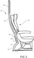
Figure 2 is a side elevation of the divider and seats; -
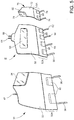
Figure 3 is a perspective view looking aft of the divider only; -
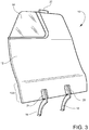
Figure 4 is a perspective view looking forward of the divider only; -
Figure 5 is a rear perspective view looking forward of two side class dividers and a center class divider according to an alternate embodiment of the invention; -
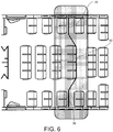
Figure 6 is a partial plan view of an aircraft cabin showing placement of contoured class dividers according to embodiments of the invention; - Referring now specifically to
Figure 1 of the drawings, a contouredportside class divider 10 according to one preferred embodiment of the invention is shown positioned directly behind a seat row of two business class seats "S" such as are conventionally found in commercial aircraft cabins. Such cabins typically include both structural and decorative panels and overhead stowage bins for passenger luggage and other items. Thedivider 10 includes a fixed, rigid monument in the form of apanel 12 attached to floor-mounted seat tracks "T" and the overhead stowage bin "B" of the aircraft cabin. The exact attachment configuration is dependent upon aircraft type and cabin configuration. The contouredportside class divider 10 optionally includes anattendant viewing window 14 that is inset into an outer corner of the upper part of thepanel 12 that can be defined by the airlines' cosmetic specifications. Thewindow 14 may be clear or automatically dimmable. - Referring to
Figure 2 , thedivider 10 utilizes space behind the seats "S" that is normally vacant with conventional class dividers but does not provide sufficient space for stowage or other uses. By forming thepanel 12 to closely correspond to the contour of the seatback of the seat "S", the Head Impact Criteria (HIC) requirement is optimized for the seat immediately behind thedivider 10. As shown, thepanel 12 in the rear-facing direction is generally convex with alower section 12A that is relatively flat in order to accommodate optionally suppliedpockets 22 for use by occupants of aft-positioned seats. Threepockets 22 are shown reflecting that the seats behind thedivider 10 are main cabin seats, which are typically arranged in groups of three. The spacing provides the ability for the aft seats (not shown) to be moved forward up to four (4) inches towards thedivider 10, improving seat spacing in the cabin. Thepanel 12 is elevated off the floor bysupport legs divider 10. - The
legs panel 12, particularly if it is accidentally impacted by excessive recline of the seatback of the seat "S", or if pulled rearwardly by a seated passenger as an aid to rising out of an occupied seat. The top end of thedivider 10 is secured against deflection by aconnector 20 that attaches thedivider 10 to an overhead structure below the bins "B". Therefore, both the top and bottom of thedivider 10 are preferably secured against movement. Sufficient space remains between thepanel 12 and the seats "S" to allow for the usual amount of seatback recline. Thepanel 12 also provides additional legroom for the occupants of seats aft of thedivider 10. -
Figures 3 and4 , together with previously referencedFigure 2 , show the bowed configuration of thelegs legs brackets Figure 3 . - A
starboard divider 70 having the same characteristics would be provided for use on the starboard side of the aircraft cabin. - Referring now to
Figure 5 , a port, center and starboard dividers according to a further embodiment of the invention are shown atreference numerals -
Port divider 30 includes apanel 32 attached to floor-mounted seat tracks and the overhead stowage bin of the aircraft cabin in a manner similar to that shown inFigures 1 and2 . The exact attachment configuration is dependent upon aircraft type and cabin configuration. Thedivider 30 optionally includes anattendant viewing window 34 that is inset into an outer corner of the upper part of thepanel 32 that can be defined by the airlines' cosmetic specifications. Thewindow 34 may be clear or automatically dimmable.Legs panel 32 in the rear-facing direction is generally convex with alower section 32A that is relatively flat in order to accommodate optionally suppliedpockets 40 for use by occupants of aft-positioned seats. The profile of the top end of thepanel 32 is curved to fit a storage bin configuration different than that shown inFigures 1-4 , is secured against deflection by aconnector 42 that attaches thedivider 30 to an overhead structure, not shown. - The
center divider 50 includes apanel 52 attached to floor-mounted seat tracks and the overhead stowage bin of the aircraft cabin in a manner similar to that shown inFigures 1 and2 . The exact attachment configuration is dependent upon aircraft type and cabin configuration. Thedivider 50 optionally includes anattendant viewing window 54 that is inset into an outer corner of the upper part of thepanel 32 that can be defined by the airlines' cosmetic specifications. Thewindow 54 may be clear or automatically dimmable.Legs panel 52 in the rear-facing direction is generally convex with alower section 52A that is relatively flat in order to accommodate optionally suppliedpockets 68 for use by occupants of aft-positioned seats. The profile of the top end of thepanel 52 is secured against deflection byconnectors divider 50 to an overhead structure, not shown. - Starboard
side divider 70 includes apanel 72 attached to floor-mounted seat tracks and the overhead stowage bin of the aircraft cabin in a manner similar to that shown inFigures 1 and2 . The exact attachment configuration is dependent upon aircraft type and cabin configuration. Thedivider 70 optionally includes anattendant viewing window 74 that is inset into an outer corner of the upper part of thepanel 72 that can be defined by the airlines' cosmetic specifications. Theviewing window 74 may be clear or automatically dimmable.Legs panel 72 in the rear-facing direction is generally convex with alower section 72A that is relatively flat in order to accommodate optionally suppliedpockets 80 for use by occupants of aft-positioned seats. The profile of the top end of thepanel 32 is curved to fit a storage bin configuration different than that shown inFigures 1-4 , is secured against deflection by aconnector 82 that attaches thedivider 70 to an overhead structure, not shown. - As shown in
Figure 6 , the port side, center and starboardside class dividers - A contoured class divider according to the invention has been described with reference to specific embodiments and examples. Various details of the invention maybe changed without departing from the scope of the invention. Furthermore, the foregoing description of the preferred embodiments of the invention and best mode for practicing the invention are provided for the purpose of illustration only and not for the purpose of limitation, the invention being defined by the claims.
Claims (15)
- A contoured class divider (10) for dividing an aircraft cabin according to a predetermined class arrangement, comprising a divider comprising:(a) a panel (12) having an aft-facing convex contour closely matching an aft-facing contour of a seatback of a seat (S) positioned directly forward of the panel (12) and adapted for being positioned in closely, spaced-apart relation to the seatback for providing additional space forward of a seat positioned aft of the panel;(b) at least one leg (16,18) having an upper end attached to a lower end of the panel for supporting the panel on an aircraft cabin deck, the leg having a convex, rear-facing shape and a base for attaching the leg to the cabin deck; and(c) at least one connector (20) positioned proximate a top end of the panel for attachment to an overhead structural element (B) of the aircraft cabin for positioning the top end of the panel in a predetermined fixed location.
- A contoured class divider according to claim 1, wherein the class divider (10) is shaped to be positioned adjacent a curved fuselage wall of the cabin,
- A contoured class divider according to claim 1 or 2, wherein the class divider includes a viewing window (14) positioned in the panel for providing a flight attendant with the ability to observe areas of the cabin through the viewing window.
- A contoured class divider according to claim 3, wherein the viewing window (14) is asymmetrically positioned within the perimeter of the panel on a side edge of the panel adapted to be positioned inboard of an opposing outboard side edge of the panel.
- A contoured class divider according to any of claims 1-4, wherein the panel (12) includes a planar section (12A) positioned below the convex contour for supporting at least one pocket (22) thereon.
- A contoured class divider according to any of claims 1-5, wherein the panel (12) includes a plurality of laterally-spaced legs (16,18) for supporting the panel on the aircraft cabin deck.
- A contoured class divider according to any of claims 1-6, wherein the divider panel (12) has a width from an outboard side edge to an inboard side edge sufficient to divide a plurality of laterally-adjacent seats in a cabin forward of the divider cabin from a plurality of laterally-adjacent seats in a cabin aft of the divider.
- A contoured class divider system for dividing an aircraft cabin according to a predetermined class arrangement, comprising:(a) a first divider (30), according to any of claims 1-7, wherein the panel is a first panel (32), wherein the first divider is shaped to be positioned adjacent a curved left fuselage wall of the cabin;(b) a second divider (70), according to any of claims 1-7, wherein the panel is a second panel (72), wherein the second divider is shaped to be positioned adjacent a curved right fuselage wall of the cabin; and(c) a third divider (50), according to any of claims 1-7, wherein the panel is a third panel (52), wherein the third divider (50) is adapted to be positioned between the first (30) and second (70) dividers and laterally separated from the first and second dividers by respective left and right cabin aisles.
- A contoured class divider system according to claim 8, wherein the first and second dividers (30,70) are shaped to be positioned adjacent curved respective left and right fuselage walls of the cabin.
- A contoured class divider system according to claim 8 or 9, wherein the viewing windows (34,74) of the first and second class dividers are asymmetrically positioned within the perimeter of respective first and second panels (32, 72) on a side edge of the panels and adapted to be positioned inboard of an opposing outboard side edge of the first and second panels.
- A contoured class divider system according to any of claims 8-10, wherein the third panel (52) is symmetrical between a left side edge and a right side edge.
- A contoured class divider system according to any of claims 8-11, wherein the first, second and third panels (30,50,70) include respective planar sections (32A,52A,72A) positioned below the convex contour for supporting at least one pocket (40,68,80) thereon.
- A contoured class divider system according to any of claims 8-12, wherein the first, second and third dividers (30,50,70) each have a width sufficient to divide a plurality of laterally-adjacent seats in a cabin forward of the first, second and third dividers from a plurality of laterally-adjacent seats in a cabin aft of the first, second and third dividers.
- A contoured class divider system according to any of claims 8-13, wherein the viewing window (54) of the third divider P(50) is centrally positioned in the third panel (52).
- A contoured class divider system according to any of claims 8-14, wherein the viewing window (54) of the third divider (50) is centrally positioned in the third pane (52) and is rectangular.
Applications Claiming Priority (2)
| Application Number | Priority Date | Filing Date | Title |
|---|---|---|---|
| US201662317706P | 2016-04-04 | 2016-04-04 | |
| PCT/US2016/032061 WO2017176298A1 (en) | 2016-04-04 | 2016-05-12 | Contoured class divider |
Publications (2)
| Publication Number | Publication Date |
|---|---|
| EP3439957A1 EP3439957A1 (en) | 2019-02-13 |
| EP3439957B1 true EP3439957B1 (en) | 2020-05-20 |
Family
ID=56027242
Family Applications (1)
| Application Number | Title | Priority Date | Filing Date |
|---|---|---|---|
| EP16724239.5A Active EP3439957B1 (en) | 2016-04-04 | 2016-05-12 | Contoured class divider |
Country Status (5)
| Country | Link |
|---|---|
| US (1) | US10370106B2 (en) |
| EP (1) | EP3439957B1 (en) |
| CN (1) | CN109071022B (en) |
| CA (1) | CA3019770C (en) |
| WO (1) | WO2017176298A1 (en) |
Cited By (1)
| Publication number | Priority date | Publication date | Assignee | Title |
|---|---|---|---|---|
| DE102022120148A1 (en) | 2022-08-10 | 2024-02-15 | Zim Aircraft Seating Gmbh | Airplane cabin divider |
Families Citing this family (12)
| Publication number | Priority date | Publication date | Assignee | Title |
|---|---|---|---|---|
| DE102015226664A1 (en) * | 2015-12-23 | 2017-06-29 | Airbus Operations Gmbh | Passenger seat with a sliding seat element and passenger cabin area |
| DE102016104794A1 (en) * | 2016-03-15 | 2017-09-21 | Airbus Operations Gmbh | Partition module for a cabin of a vehicle for the optical and mechanical separation of different cabin areas |
| US10843799B2 (en) * | 2016-04-04 | 2020-11-24 | B/E Aerospace, Inc. | Contoured class divider |
| US10676194B2 (en) | 2016-04-04 | 2020-06-09 | B/E Aerospace, Inc. | Contoured class divider |
| WO2017176298A1 (en) * | 2016-04-04 | 2017-10-12 | B/E Aerospace, Inc. | Contoured class divider |
| US11066171B2 (en) * | 2016-04-04 | 2021-07-20 | B/E Aerospace, Inc. | Contoured class divider |
| US11230380B2 (en) * | 2018-01-16 | 2022-01-25 | The Boeing Company | Interior aircraft frame assembly for furnishings |
| EP3841017B1 (en) * | 2018-08-24 | 2024-04-24 | Safran Seats USA LLC | Removable modular privacy assembly |
| US11034452B2 (en) * | 2018-10-29 | 2021-06-15 | Safran Cabin Inc. | Aircraft with staggered seating arrangement |
| US10919631B2 (en) * | 2018-10-29 | 2021-02-16 | Safran Cabin Inc. | Aircraft with multiple doors and multiple zones |
| US11780584B2 (en) | 2021-11-16 | 2023-10-10 | The Boeing Company | Panel attachment in a vehicle configured for low profile removal and reattachment |
| US11753166B2 (en) * | 2021-11-16 | 2023-09-12 | The Boeing Company | Panel assembly for a vehicle |
Family Cites Families (76)
| Publication number | Priority date | Publication date | Assignee | Title |
|---|---|---|---|---|
| US2268927A (en) | 1938-07-05 | 1942-01-06 | William E Demme | Display rack |
| US3423121A (en) | 1967-02-10 | 1969-01-21 | Martin Lipkin | Protective partition against deceleration |
| FR2612151B1 (en) | 1987-03-12 | 1992-04-10 | Sicma Aero Seat | STRUCTURE WITH AN ENERGY ABSORBING DEVICE AND RESISTANT TO DYNAMIC EFFORTS FORMING A FLOOR FOR THE SEAT OF AN AIR TRANSPORTATION APPARATUS AND SEAT COMPRISING SUCH A STRUCTURE |
| DE3802331A1 (en) | 1988-01-27 | 1989-09-07 | Messerschmitt Boelkow Blohm | SAFETY DEVICE FOR AIRCRAFT |
| GB8821065D0 (en) | 1988-09-08 | 1988-10-05 | Magerik Ltd | Aircraft cabin divider |
| US5133587A (en) | 1989-11-20 | 1992-07-28 | Hadden Jr James R | Seat |
| FR2671838B1 (en) | 1991-01-22 | 1995-01-13 | Sicma Aero Seat | ENERGY ABSORPTION DEVICE, BASE-FORMING STRUCTURE FOR SEAT OF AIR TRANSPORT APPARATUS COMPRISING SUCH A DEVICE, AND SEAT COMPRISING SUCH A STRUCTURE. |
| JP2520058B2 (en) | 1991-05-09 | 1996-07-31 | 小糸工業株式会社 | Seat leg structure that absorbs impact energy |
| GB9114626D0 (en) * | 1991-07-06 | 1991-08-21 | Magerik Ltd | Aircraft cabin divider |
| US5165626A (en) * | 1991-10-28 | 1992-11-24 | Ringger George J | Partial class divider assembly for an aircraft |
| DE4141606C2 (en) | 1991-12-17 | 1994-05-11 | Deutsche Aerospace Airbus | Device for dividing an aircraft cabin |
| US5340059A (en) | 1992-02-24 | 1994-08-23 | Futureflite Corporation | Energy absorbing cabinet for aircraft bulkheads |
| DE4244656C2 (en) | 1992-03-27 | 1997-03-20 | Josef Gloeckl | Active dynamic seat device |
| US5482230A (en) | 1993-06-25 | 1996-01-09 | B E Aerospace, Inc. | Vehicle bulkhead safety system |
| US5350144A (en) * | 1993-08-13 | 1994-09-27 | Lary Fredric C | Mounting fixture for a hand-held hair dryer |
| DE4437133C2 (en) * | 1994-10-18 | 1996-08-29 | Daimler Benz Aerospace Airbus | Partition for the cabin of a passenger plane |
| GB9425078D0 (en) * | 1994-12-13 | 1995-02-08 | British Airways Plc | A seating unit |
| US5649721A (en) * | 1995-01-20 | 1997-07-22 | The Boeing Co. | Impact protection apparatus |
| DE19526525C1 (en) * | 1995-07-20 | 1997-02-13 | Daimler Benz Aerospace Airbus | Device for dividing an aircraft cabin |
| US5716026A (en) * | 1995-08-14 | 1998-02-10 | Pascasio; Vidal | High-capacity, high-comfort split-level seating for transport and stationary applications |
| US5788185A (en) * | 1996-05-17 | 1998-08-04 | Impact Dynamics, Inc. | Aircraft seat having improved user lumbar load characteristics during a crash event |
| FR2791031B1 (en) | 1999-03-19 | 2001-05-18 | Adder Sa | MOBILE CLASS SEPARATOR IN A COCKPIT LIKE AN AIRCRAFT |
| US6692069B2 (en) * | 2001-07-20 | 2004-02-17 | B E Aerospace, Inc. | Aircraft sleeper seat |
| US6792875B2 (en) * | 2001-11-21 | 2004-09-21 | B E Aerospace, Inc. | Passenger seat meal tray assembly and passenger seat |
| US6672662B1 (en) * | 2001-12-26 | 2004-01-06 | Lear Corporation | Vehicle seat |
| FR2842497B1 (en) * | 2002-07-19 | 2004-10-01 | Airbus | AIRCRAFT CABIN MODULE FOR PASSENGERS |
| DE10307870A1 (en) * | 2003-02-25 | 2004-09-09 | Airbus Deutschland Gmbh | Seat row arrangement in a passenger cabin of a commercial aircraft |
| DE10322611B3 (en) | 2003-05-20 | 2004-08-12 | Daimlerchrysler Ag | Partition wall for automobile e.g. van, dividing load space from driving cab with hinged sections allowing parallel configuration at rear of adjustable passenger seat |
| US20060006704A1 (en) * | 2003-12-15 | 2006-01-12 | Be Aerospace, Inc. | Vehicle seating with storage feature |
| FR2877281B1 (en) | 2004-11-02 | 2007-02-02 | Productions Sa Sa B V | VEHICLE CAR INCLUDING A RECLINING SEAT AND A SEPARATION PANEL |
| DE102005009750B4 (en) | 2005-03-03 | 2009-04-23 | Airbus Deutschland Gmbh | Assembly comprising a seat and a flight attendant seat |
| EP1698552B1 (en) * | 2005-03-03 | 2010-07-07 | Airbus Operations GmbH | Arrangement of first and second parts |
| US20070222266A1 (en) * | 2006-03-21 | 2007-09-27 | Ditto Sales, Inc. | Nestable and stackable chair |
| US7721991B2 (en) * | 2006-10-12 | 2010-05-25 | Be Aerospace, Inc. | Translatable and rotatable passenger seat |
| US8167244B2 (en) * | 2008-02-11 | 2012-05-01 | B E Aerospace, Inc. | Class divider for aircraft cabin |
| US8960602B2 (en) | 2008-02-27 | 2015-02-24 | Airbus Operations Gmbh | Partition wall in an aircraft |
| DK2283190T3 (en) * | 2008-03-28 | 2021-02-08 | Noble Environmental Tech Corporation | CONSTRUCTED SHAPED FIBER SHEET PANELS, PANEL MANUFACTURING METHODS, AND PRODUCTS MADE FROM THE PANELS |
| GB2459703B (en) | 2008-05-02 | 2012-04-11 | Nissan Motor Mfg Uk Ltd | Vehicle with adjustable partition wall |
| US8118684B2 (en) * | 2008-10-30 | 2012-02-21 | Mattel, Inc. | Infant support structure with a collapsible frame |
| DE102009041581B4 (en) * | 2009-09-15 | 2011-09-29 | Airbus Operations Gmbh | Device for defining a crew resting area and method for putting into operation of such a device |
| US8590838B2 (en) * | 2010-04-20 | 2013-11-26 | Be Intellectual Property, Inc. | Aircraft interior lavatory |
| EP2709873B1 (en) * | 2011-05-20 | 2020-07-08 | Zodiac Seats France | Kinematic seat with elastic pivot |
| JP5472223B2 (en) | 2011-07-11 | 2014-04-16 | トヨタ自動車株式会社 | Fender panel mounting structure |
| DE102011116519A1 (en) * | 2011-10-20 | 2013-04-25 | Airbus Operations Gmbh | Flight attendant seat, line up with a flight attendant seat and airplane area |
| WO2013109751A1 (en) * | 2012-01-17 | 2013-07-25 | Zodiac Seats Us Llc | Passenger seat |
| JP5952956B2 (en) * | 2012-03-20 | 2016-07-13 | ビーイー・エアロスペース・インコーポレーテッドB/E Aerospace, Inc. | Premium class aircraft passenger suite with independent seating area |
| US8814089B2 (en) * | 2012-11-07 | 2014-08-26 | Heath Tecna Inc. | Aircraft class divider |
| US8814088B2 (en) * | 2012-03-21 | 2014-08-26 | Health Tecna Inc. | Aircraft class divider |
| JP5936773B2 (en) * | 2012-07-11 | 2016-06-22 | ビーイー・エアロスペース・インコーポレーテッドB/E Aerospace, Inc. | Passenger seat bulkhead splitting seat class |
| DE102012021430B4 (en) * | 2012-10-30 | 2023-01-12 | Airbus Operations Gmbh | Device for separating two zones of a passenger cabin |
| US9254918B2 (en) * | 2012-12-11 | 2016-02-09 | C&D Zodiac, Inc. | Aircraft aisle partition with swinging doors |
| US20140175219A1 (en) * | 2012-12-11 | 2014-06-26 | C&D Zodiac, Inc. | Fixed aircraft aisle partition with lighting |
| EP2743183A1 (en) * | 2012-12-14 | 2014-06-18 | Airbus Operations GmbH | Convertible cabin attendant seat |
| CN105263801B (en) | 2013-04-05 | 2017-11-24 | 新加坡科技宇航 | Leg assemblies for passenger seat, chair frame and passenger seat for passenger seat |
| EP2796371B1 (en) * | 2013-04-23 | 2019-11-20 | Airbus Operations GmbH | Cabin attendant seat with additional support |
| DE102013110500A1 (en) * | 2013-09-23 | 2015-04-16 | Airbus Operations Gmbh | Apparatus for supporting a vehicle attendant seat in a cabin of a vehicle, cabin assembly in a vehicle and vehicle having at least one cabin assembly |
| US20160296419A1 (en) * | 2013-12-03 | 2016-10-13 | Koninklijke Philips N.V. | Moving box automated cardio pulmonary resuscitation device |
| US9919803B2 (en) * | 2014-04-04 | 2018-03-20 | B/E Aerospace, Inc. | Aircraft seat base frame |
| EP2927124B1 (en) * | 2014-04-04 | 2020-10-28 | Airbus Operations GmbH | Foldable divider device for an aircraft cabin |
| EP2927126B1 (en) | 2014-04-04 | 2020-10-28 | Airbus Operations GmbH | Divider element for an aircraft cabin |
| US10464677B2 (en) * | 2014-04-07 | 2019-11-05 | B/E Aerospace, Inc. | Aircraft modular lavatory system |
| US9862491B2 (en) * | 2014-04-07 | 2018-01-09 | B/E Aerospace, Inc. | Modular lavatory system optimized for narrow body commercial aircraft |
| US9352839B2 (en) | 2014-10-02 | 2016-05-31 | Amsafe, Inc. | Active positioning airbag assembly and associated systems and methods |
| CN204351446U (en) | 2015-01-12 | 2015-05-27 | 中山市西区青原贸易代理服务部 | The bracing or strutting arrangement of basket cot |
| US9499271B2 (en) * | 2015-04-09 | 2016-11-22 | The Boeing Company | Systems and methods for positioning a section divider assembly within a vehicle |
| WO2016168441A1 (en) * | 2015-04-14 | 2016-10-20 | B/E Aerospace, Inc. | Modular aircraft closet |
| US10562630B2 (en) * | 2015-11-05 | 2020-02-18 | C&D Zodiac, Inc. | Aircraft with partition system |
| DE102016104794A1 (en) | 2016-03-15 | 2017-09-21 | Airbus Operations Gmbh | Partition module for a cabin of a vehicle for the optical and mechanical separation of different cabin areas |
| US10112719B2 (en) | 2016-03-18 | 2018-10-30 | The Boeing Company | Deployable clearance panel system, method, and assembly for a monument within an internal cabin of an aircraft |
| US11066171B2 (en) * | 2016-04-04 | 2021-07-20 | B/E Aerospace, Inc. | Contoured class divider |
| US10843799B2 (en) * | 2016-04-04 | 2020-11-24 | B/E Aerospace, Inc. | Contoured class divider |
| US20170283065A1 (en) * | 2016-04-04 | 2017-10-05 | B/E Aerospace, Inc. | Aircraft Interior Surface and Method of Illuminating an Aircraft Interior Surface |
| US10676194B2 (en) * | 2016-04-04 | 2020-06-09 | B/E Aerospace, Inc. | Contoured class divider |
| WO2017176298A1 (en) * | 2016-04-04 | 2017-10-12 | B/E Aerospace, Inc. | Contoured class divider |
| US10106187B1 (en) | 2016-08-18 | 2018-10-23 | Mark Edward Farrar | Baby carrier device |
| WO2018071596A1 (en) | 2016-10-12 | 2018-04-19 | B/E Aerospace, Inc. | Contoured class divider |
-
2016
- 2016-05-12 WO PCT/US2016/032061 patent/WO2017176298A1/en active Application Filing
- 2016-05-12 US US15/153,104 patent/US10370106B2/en active Active
- 2016-05-12 CN CN201680082751.XA patent/CN109071022B/en active Active
- 2016-05-12 CA CA3019770A patent/CA3019770C/en active Active
- 2016-05-12 EP EP16724239.5A patent/EP3439957B1/en active Active
Cited By (2)
| Publication number | Priority date | Publication date | Assignee | Title |
|---|---|---|---|---|
| DE102022120148A1 (en) | 2022-08-10 | 2024-02-15 | Zim Aircraft Seating Gmbh | Airplane cabin divider |
| WO2024033166A1 (en) | 2022-08-10 | 2024-02-15 | Zim Aircraft Seating Gmbh | Aircraft cabin divider |
Also Published As
| Publication number | Publication date |
|---|---|
| WO2017176298A1 (en) | 2017-10-12 |
| US10370106B2 (en) | 2019-08-06 |
| CA3019770C (en) | 2023-10-17 |
| CN109071022B (en) | 2022-06-03 |
| CN109071022A (en) | 2018-12-21 |
| EP3439957A1 (en) | 2019-02-13 |
| US20170283060A1 (en) | 2017-10-05 |
| CA3019770A1 (en) | 2017-10-12 |
Similar Documents
| Publication | Publication Date | Title |
|---|---|---|
| EP3439957B1 (en) | Contoured class divider | |
| EP3356229B1 (en) | Airliner passenger suite seating arrangements with shared aisle suite access | |
| US11130577B2 (en) | Universal rest seats | |
| EP2289798B1 (en) | Seating for a passenger vehicle | |
| EP2240367B1 (en) | Class divider for aircraft cabin | |
| US11685529B2 (en) | Seating arrangement | |
| US10953987B2 (en) | Aircraft interior configuration with flexible use space | |
| US20180273185A1 (en) | Aircraft cabin arrangement optimised for the installation of seats for the flight crew | |
| US11679880B2 (en) | Seating arrangements for a vehicle cabin | |
| US7717372B2 (en) | Reduced-perimeter aircraft | |
| EP3233636B1 (en) | Lavatory, first class, and business class seat integration | |
| US20220041284A1 (en) | Arrangement of seat units, in particular for an aircraft | |
| US10322809B2 (en) | Molded sidewall armrest between fuselage frame bays | |
| US11006760B2 (en) | Convertible seating unit and seating arrangement | |
| EP4015385B1 (en) | Aircraft passenger seat row with cabin attendant seat |
Legal Events
| Date | Code | Title | Description |
|---|---|---|---|
| STAA | Information on the status of an ep patent application or granted ep patent |
Free format text: STATUS: THE INTERNATIONAL PUBLICATION HAS BEEN MADE |
|
| PUAI | Public reference made under article 153(3) epc to a published international application that has entered the european phase |
Free format text: ORIGINAL CODE: 0009012 |
|
| STAA | Information on the status of an ep patent application or granted ep patent |
Free format text: STATUS: REQUEST FOR EXAMINATION WAS MADE |
|
| 17P | Request for examination filed |
Effective date: 20180824 |
|
| AK | Designated contracting states |
Kind code of ref document: A1 Designated state(s): AL AT BE BG CH CY CZ DE DK EE ES FI FR GB GR HR HU IE IS IT LI LT LU LV MC MK MT NL NO PL PT RO RS SE SI SK SM TR |
|
| AX | Request for extension of the european patent |
Extension state: BA ME |
|
| RIN1 | Information on inventor provided before grant (corrected) |
Inventor name: MCKEE, JEFFEREY M. Inventor name: PAPKE, ROBERT Inventor name: CLAFLIN, SHAWN |
|
| DAV | Request for validation of the european patent (deleted) | ||
| DAX | Request for extension of the european patent (deleted) | ||
| GRAP | Despatch of communication of intention to grant a patent |
Free format text: ORIGINAL CODE: EPIDOSNIGR1 |
|
| STAA | Information on the status of an ep patent application or granted ep patent |
Free format text: STATUS: GRANT OF PATENT IS INTENDED |
|
| INTG | Intention to grant announced |
Effective date: 20200122 |
|
| RIN1 | Information on inventor provided before grant (corrected) |
Inventor name: CAFLIN, SHAWN Inventor name: PAPKE, ROBERT Inventor name: MCKEE, JEFFEREY M. |
|
| GRAS | Grant fee paid |
Free format text: ORIGINAL CODE: EPIDOSNIGR3 |
|
| GRAA | (expected) grant |
Free format text: ORIGINAL CODE: 0009210 |
|
| STAA | Information on the status of an ep patent application or granted ep patent |
Free format text: STATUS: THE PATENT HAS BEEN GRANTED |
|
| AK | Designated contracting states |
Kind code of ref document: B1 Designated state(s): AL AT BE BG CH CY CZ DE DK EE ES FI FR GB GR HR HU IE IS IT LI LT LU LV MC MK MT NL NO PL PT RO RS SE SI SK SM TR |
|
| REG | Reference to a national code |
Ref country code: GB Ref legal event code: FG4D |
|
| REG | Reference to a national code |
Ref country code: CH Ref legal event code: EP |
|
| REG | Reference to a national code |
Ref country code: DE Ref legal event code: R096 Ref document number: 602016036716 Country of ref document: DE |
|
| REG | Reference to a national code |
Ref country code: AT Ref legal event code: REF Ref document number: 1272459 Country of ref document: AT Kind code of ref document: T Effective date: 20200615 |
|
| REG | Reference to a national code |
Ref country code: NL Ref legal event code: FP |
|
| REG | Reference to a national code |
Ref country code: LT Ref legal event code: MG4D |
|
| PG25 | Lapsed in a contracting state [announced via postgrant information from national office to epo] |
Ref country code: LT Free format text: LAPSE BECAUSE OF FAILURE TO SUBMIT A TRANSLATION OF THE DESCRIPTION OR TO PAY THE FEE WITHIN THE PRESCRIBED TIME-LIMIT Effective date: 20200520 Ref country code: GR Free format text: LAPSE BECAUSE OF FAILURE TO SUBMIT A TRANSLATION OF THE DESCRIPTION OR TO PAY THE FEE WITHIN THE PRESCRIBED TIME-LIMIT Effective date: 20200821 Ref country code: FI Free format text: LAPSE BECAUSE OF FAILURE TO SUBMIT A TRANSLATION OF THE DESCRIPTION OR TO PAY THE FEE WITHIN THE PRESCRIBED TIME-LIMIT Effective date: 20200520 Ref country code: NO Free format text: LAPSE BECAUSE OF FAILURE TO SUBMIT A TRANSLATION OF THE DESCRIPTION OR TO PAY THE FEE WITHIN THE PRESCRIBED TIME-LIMIT Effective date: 20200820 Ref country code: IS Free format text: LAPSE BECAUSE OF FAILURE TO SUBMIT A TRANSLATION OF THE DESCRIPTION OR TO PAY THE FEE WITHIN THE PRESCRIBED TIME-LIMIT Effective date: 20200920 Ref country code: SE Free format text: LAPSE BECAUSE OF FAILURE TO SUBMIT A TRANSLATION OF THE DESCRIPTION OR TO PAY THE FEE WITHIN THE PRESCRIBED TIME-LIMIT Effective date: 20200520 Ref country code: PT Free format text: LAPSE BECAUSE OF FAILURE TO SUBMIT A TRANSLATION OF THE DESCRIPTION OR TO PAY THE FEE WITHIN THE PRESCRIBED TIME-LIMIT Effective date: 20200921 |
|
| PG25 | Lapsed in a contracting state [announced via postgrant information from national office to epo] |
Ref country code: RS Free format text: LAPSE BECAUSE OF FAILURE TO SUBMIT A TRANSLATION OF THE DESCRIPTION OR TO PAY THE FEE WITHIN THE PRESCRIBED TIME-LIMIT Effective date: 20200520 Ref country code: LV Free format text: LAPSE BECAUSE OF FAILURE TO SUBMIT A TRANSLATION OF THE DESCRIPTION OR TO PAY THE FEE WITHIN THE PRESCRIBED TIME-LIMIT Effective date: 20200520 Ref country code: HR Free format text: LAPSE BECAUSE OF FAILURE TO SUBMIT A TRANSLATION OF THE DESCRIPTION OR TO PAY THE FEE WITHIN THE PRESCRIBED TIME-LIMIT Effective date: 20200520 Ref country code: BG Free format text: LAPSE BECAUSE OF FAILURE TO SUBMIT A TRANSLATION OF THE DESCRIPTION OR TO PAY THE FEE WITHIN THE PRESCRIBED TIME-LIMIT Effective date: 20200820 |
|
| REG | Reference to a national code |
Ref country code: AT Ref legal event code: MK05 Ref document number: 1272459 Country of ref document: AT Kind code of ref document: T Effective date: 20200520 |
|
| PG25 | Lapsed in a contracting state [announced via postgrant information from national office to epo] |
Ref country code: AL Free format text: LAPSE BECAUSE OF FAILURE TO SUBMIT A TRANSLATION OF THE DESCRIPTION OR TO PAY THE FEE WITHIN THE PRESCRIBED TIME-LIMIT Effective date: 20200520 |
|
| PG25 | Lapsed in a contracting state [announced via postgrant information from national office to epo] |
Ref country code: CZ Free format text: LAPSE BECAUSE OF FAILURE TO SUBMIT A TRANSLATION OF THE DESCRIPTION OR TO PAY THE FEE WITHIN THE PRESCRIBED TIME-LIMIT Effective date: 20200520 Ref country code: IT Free format text: LAPSE BECAUSE OF FAILURE TO SUBMIT A TRANSLATION OF THE DESCRIPTION OR TO PAY THE FEE WITHIN THE PRESCRIBED TIME-LIMIT Effective date: 20200520 Ref country code: DK Free format text: LAPSE BECAUSE OF FAILURE TO SUBMIT A TRANSLATION OF THE DESCRIPTION OR TO PAY THE FEE WITHIN THE PRESCRIBED TIME-LIMIT Effective date: 20200520 Ref country code: EE Free format text: LAPSE BECAUSE OF FAILURE TO SUBMIT A TRANSLATION OF THE DESCRIPTION OR TO PAY THE FEE WITHIN THE PRESCRIBED TIME-LIMIT Effective date: 20200520 Ref country code: AT Free format text: LAPSE BECAUSE OF FAILURE TO SUBMIT A TRANSLATION OF THE DESCRIPTION OR TO PAY THE FEE WITHIN THE PRESCRIBED TIME-LIMIT Effective date: 20200520 Ref country code: SM Free format text: LAPSE BECAUSE OF FAILURE TO SUBMIT A TRANSLATION OF THE DESCRIPTION OR TO PAY THE FEE WITHIN THE PRESCRIBED TIME-LIMIT Effective date: 20200520 Ref country code: RO Free format text: LAPSE BECAUSE OF FAILURE TO SUBMIT A TRANSLATION OF THE DESCRIPTION OR TO PAY THE FEE WITHIN THE PRESCRIBED TIME-LIMIT Effective date: 20200520 Ref country code: ES Free format text: LAPSE BECAUSE OF FAILURE TO SUBMIT A TRANSLATION OF THE DESCRIPTION OR TO PAY THE FEE WITHIN THE PRESCRIBED TIME-LIMIT Effective date: 20200520 |
|
| REG | Reference to a national code |
Ref country code: DE Ref legal event code: R097 Ref document number: 602016036716 Country of ref document: DE |
|
| PG25 | Lapsed in a contracting state [announced via postgrant information from national office to epo] |
Ref country code: SK Free format text: LAPSE BECAUSE OF FAILURE TO SUBMIT A TRANSLATION OF THE DESCRIPTION OR TO PAY THE FEE WITHIN THE PRESCRIBED TIME-LIMIT Effective date: 20200520 Ref country code: PL Free format text: LAPSE BECAUSE OF FAILURE TO SUBMIT A TRANSLATION OF THE DESCRIPTION OR TO PAY THE FEE WITHIN THE PRESCRIBED TIME-LIMIT Effective date: 20200520 |
|
| PLBE | No opposition filed within time limit |
Free format text: ORIGINAL CODE: 0009261 |
|
| STAA | Information on the status of an ep patent application or granted ep patent |
Free format text: STATUS: NO OPPOSITION FILED WITHIN TIME LIMIT |
|
| 26N | No opposition filed |
Effective date: 20210223 |
|
| PG25 | Lapsed in a contracting state [announced via postgrant information from national office to epo] |
Ref country code: SI Free format text: LAPSE BECAUSE OF FAILURE TO SUBMIT A TRANSLATION OF THE DESCRIPTION OR TO PAY THE FEE WITHIN THE PRESCRIBED TIME-LIMIT Effective date: 20200520 |
|
| REG | Reference to a national code |
Ref country code: CH Ref legal event code: PL |
|
| PG25 | Lapsed in a contracting state [announced via postgrant information from national office to epo] |
Ref country code: LI Free format text: LAPSE BECAUSE OF NON-PAYMENT OF DUE FEES Effective date: 20210531 Ref country code: LU Free format text: LAPSE BECAUSE OF NON-PAYMENT OF DUE FEES Effective date: 20210512 Ref country code: MC Free format text: LAPSE BECAUSE OF FAILURE TO SUBMIT A TRANSLATION OF THE DESCRIPTION OR TO PAY THE FEE WITHIN THE PRESCRIBED TIME-LIMIT Effective date: 20200520 Ref country code: CH Free format text: LAPSE BECAUSE OF NON-PAYMENT OF DUE FEES Effective date: 20210531 |
|
| REG | Reference to a national code |
Ref country code: BE Ref legal event code: MM Effective date: 20210531 |
|
| PG25 | Lapsed in a contracting state [announced via postgrant information from national office to epo] |
Ref country code: IE Free format text: LAPSE BECAUSE OF NON-PAYMENT OF DUE FEES Effective date: 20210512 |
|
| PG25 | Lapsed in a contracting state [announced via postgrant information from national office to epo] |
Ref country code: BE Free format text: LAPSE BECAUSE OF NON-PAYMENT OF DUE FEES Effective date: 20210531 |
|
| PG25 | Lapsed in a contracting state [announced via postgrant information from national office to epo] |
Ref country code: CY Free format text: LAPSE BECAUSE OF FAILURE TO SUBMIT A TRANSLATION OF THE DESCRIPTION OR TO PAY THE FEE WITHIN THE PRESCRIBED TIME-LIMIT Effective date: 20200520 |
|
| PGFP | Annual fee paid to national office [announced via postgrant information from national office to epo] |
Ref country code: NL Payment date: 20230419 Year of fee payment: 8 |
|
| PG25 | Lapsed in a contracting state [announced via postgrant information from national office to epo] |
Ref country code: HU Free format text: LAPSE BECAUSE OF FAILURE TO SUBMIT A TRANSLATION OF THE DESCRIPTION OR TO PAY THE FEE WITHIN THE PRESCRIBED TIME-LIMIT; INVALID AB INITIO Effective date: 20160512 |
|
| PGFP | Annual fee paid to national office [announced via postgrant information from national office to epo] |
Ref country code: FR Payment date: 20230420 Year of fee payment: 8 Ref country code: DE Payment date: 20230419 Year of fee payment: 8 |
|
| PGFP | Annual fee paid to national office [announced via postgrant information from national office to epo] |
Ref country code: GB Payment date: 20230420 Year of fee payment: 8 |