EP3439773B1 - Modularer oszillierender strömungsplattenreaktor - Google Patents
Modularer oszillierender strömungsplattenreaktor Download PDFInfo
- Publication number
- EP3439773B1 EP3439773B1 EP17724445.6A EP17724445A EP3439773B1 EP 3439773 B1 EP3439773 B1 EP 3439773B1 EP 17724445 A EP17724445 A EP 17724445A EP 3439773 B1 EP3439773 B1 EP 3439773B1
- Authority
- EP
- European Patent Office
- Prior art keywords
- section
- convergent
- width
- previous
- reactor
- Prior art date
- Legal status (The legal status is an assumption and is not a legal conclusion. Google has not performed a legal analysis and makes no representation as to the accuracy of the status listed.)
- Active
Links
- 230000003534 oscillatory effect Effects 0.000 title description 16
- 238000002156 mixing Methods 0.000 claims description 34
- 239000007788 liquid Substances 0.000 claims description 15
- 230000000737 periodic effect Effects 0.000 claims description 14
- 239000012530 fluid Substances 0.000 claims description 11
- 230000010355 oscillation Effects 0.000 claims description 8
- 238000002425 crystallisation Methods 0.000 claims description 7
- 230000008025 crystallization Effects 0.000 claims description 7
- 238000010521 absorption reaction Methods 0.000 claims description 5
- 238000001556 precipitation Methods 0.000 claims description 5
- 238000006243 chemical reaction Methods 0.000 claims description 4
- 238000000622 liquid--liquid extraction Methods 0.000 claims description 4
- 238000012216 screening Methods 0.000 claims description 4
- 238000000638 solvent extraction Methods 0.000 claims description 4
- 238000005516 engineering process Methods 0.000 description 16
- 239000007787 solid Substances 0.000 description 10
- 238000003070 Statistical process control Methods 0.000 description 9
- 238000012546 transfer Methods 0.000 description 9
- 238000000034 method Methods 0.000 description 8
- 230000008569 process Effects 0.000 description 7
- 238000013461 design Methods 0.000 description 6
- 239000000126 substance Substances 0.000 description 5
- 238000004140 cleaning Methods 0.000 description 4
- 230000008021 deposition Effects 0.000 description 3
- 239000011148 porous material Substances 0.000 description 3
- 230000003068 static effect Effects 0.000 description 3
- 238000005054 agglomeration Methods 0.000 description 2
- 230000002776 aggregation Effects 0.000 description 2
- 230000015572 biosynthetic process Effects 0.000 description 2
- 230000007246 mechanism Effects 0.000 description 2
- 239000002245 particle Substances 0.000 description 2
- 239000000376 reactant Substances 0.000 description 2
- 238000010900 secondary nucleation Methods 0.000 description 2
- 238000000926 separation method Methods 0.000 description 2
- WYTGDNHDOZPMIW-RCBQFDQVSA-N alstonine Natural products C1=CC2=C3C=CC=CC3=NC2=C2N1C[C@H]1[C@H](C)OC=C(C(=O)OC)[C@H]1C2 WYTGDNHDOZPMIW-RCBQFDQVSA-N 0.000 description 1
- 238000011138 biotechnological process Methods 0.000 description 1
- 230000008859 change Effects 0.000 description 1
- 239000003153 chemical reaction reagent Substances 0.000 description 1
- 230000003247 decreasing effect Effects 0.000 description 1
- 239000011521 glass Substances 0.000 description 1
- 239000007791 liquid phase Substances 0.000 description 1
- 239000002184 metal Substances 0.000 description 1
- 229910052751 metal Inorganic materials 0.000 description 1
- 239000004033 plastic Substances 0.000 description 1
- 238000012545 processing Methods 0.000 description 1
- 230000009467 reduction Effects 0.000 description 1
- 238000013341 scale-up Methods 0.000 description 1
- 239000007790 solid phase Substances 0.000 description 1
- 239000002699 waste material Substances 0.000 description 1
Images

Classifications
-
- B—PERFORMING OPERATIONS; TRANSPORTING
- B01—PHYSICAL OR CHEMICAL PROCESSES OR APPARATUS IN GENERAL
- B01F—MIXING, e.g. DISSOLVING, EMULSIFYING OR DISPERSING
- B01F25/00—Flow mixers; Mixers for falling materials, e.g. solid particles
- B01F25/40—Static mixers
- B01F25/42—Static mixers in which the mixing is affected by moving the components jointly in changing directions, e.g. in tubes provided with baffles or obstructions
- B01F25/43—Mixing tubes, e.g. wherein the material is moved in a radial or partly reversed direction
- B01F25/433—Mixing tubes wherein the shape of the tube influences the mixing, e.g. mixing tubes with varying cross-section or provided with inwardly extending profiles
- B01F25/4331—Mixers with bended, curved, coiled, wounded mixing tubes or comprising elements for bending the flow
-
- B—PERFORMING OPERATIONS; TRANSPORTING
- B01—PHYSICAL OR CHEMICAL PROCESSES OR APPARATUS IN GENERAL
- B01F—MIXING, e.g. DISSOLVING, EMULSIFYING OR DISPERSING
- B01F25/00—Flow mixers; Mixers for falling materials, e.g. solid particles
- B01F25/40—Static mixers
- B01F25/42—Static mixers in which the mixing is affected by moving the components jointly in changing directions, e.g. in tubes provided with baffles or obstructions
- B01F25/43—Mixing tubes, e.g. wherein the material is moved in a radial or partly reversed direction
- B01F25/433—Mixing tubes wherein the shape of the tube influences the mixing, e.g. mixing tubes with varying cross-section or provided with inwardly extending profiles
- B01F25/4338—Mixers with a succession of converging-diverging cross-sections, i.e. undulating cross-section
-
- B—PERFORMING OPERATIONS; TRANSPORTING
- B01—PHYSICAL OR CHEMICAL PROCESSES OR APPARATUS IN GENERAL
- B01F—MIXING, e.g. DISSOLVING, EMULSIFYING OR DISPERSING
- B01F31/00—Mixers with shaking, oscillating, or vibrating mechanisms
- B01F31/65—Mixers with shaking, oscillating, or vibrating mechanisms the materials to be mixed being directly submitted to a pulsating movement, e.g. by means of an oscillating piston or air column
-
- B—PERFORMING OPERATIONS; TRANSPORTING
- B01—PHYSICAL OR CHEMICAL PROCESSES OR APPARATUS IN GENERAL
- B01F—MIXING, e.g. DISSOLVING, EMULSIFYING OR DISPERSING
- B01F35/00—Accessories for mixers; Auxiliary operations or auxiliary devices; Parts or details of general application
- B01F35/90—Heating or cooling systems
- B01F35/92—Heating or cooling systems for heating the outside of the receptacle, e.g. heated jackets or burners
-
- B—PERFORMING OPERATIONS; TRANSPORTING
- B01—PHYSICAL OR CHEMICAL PROCESSES OR APPARATUS IN GENERAL
- B01J—CHEMICAL OR PHYSICAL PROCESSES, e.g. CATALYSIS OR COLLOID CHEMISTRY; THEIR RELEVANT APPARATUS
- B01J19/00—Chemical, physical or physico-chemical processes in general; Their relevant apparatus
- B01J19/24—Stationary reactors without moving elements inside
- B01J19/241—Stationary reactors without moving elements inside of the pulsating type
-
- B—PERFORMING OPERATIONS; TRANSPORTING
- B01—PHYSICAL OR CHEMICAL PROCESSES OR APPARATUS IN GENERAL
- B01J—CHEMICAL OR PHYSICAL PROCESSES, e.g. CATALYSIS OR COLLOID CHEMISTRY; THEIR RELEVANT APPARATUS
- B01J19/00—Chemical, physical or physico-chemical processes in general; Their relevant apparatus
- B01J19/24—Stationary reactors without moving elements inside
- B01J19/2415—Tubular reactors
- B01J19/242—Tubular reactors in series
-
- B—PERFORMING OPERATIONS; TRANSPORTING
- B01—PHYSICAL OR CHEMICAL PROCESSES OR APPARATUS IN GENERAL
- B01J—CHEMICAL OR PHYSICAL PROCESSES, e.g. CATALYSIS OR COLLOID CHEMISTRY; THEIR RELEVANT APPARATUS
- B01J19/00—Chemical, physical or physico-chemical processes in general; Their relevant apparatus
- B01J19/24—Stationary reactors without moving elements inside
- B01J19/2415—Tubular reactors
- B01J19/2425—Tubular reactors in parallel
-
- B—PERFORMING OPERATIONS; TRANSPORTING
- B01—PHYSICAL OR CHEMICAL PROCESSES OR APPARATUS IN GENERAL
- B01J—CHEMICAL OR PHYSICAL PROCESSES, e.g. CATALYSIS OR COLLOID CHEMISTRY; THEIR RELEVANT APPARATUS
- B01J19/00—Chemical, physical or physico-chemical processes in general; Their relevant apparatus
- B01J19/24—Stationary reactors without moving elements inside
- B01J19/2415—Tubular reactors
- B01J19/243—Tubular reactors spirally, concentrically or zigzag wound
-
- B—PERFORMING OPERATIONS; TRANSPORTING
- B01—PHYSICAL OR CHEMICAL PROCESSES OR APPARATUS IN GENERAL
- B01F—MIXING, e.g. DISSOLVING, EMULSIFYING OR DISPERSING
- B01F2215/00—Auxiliary or complementary information in relation with mixing
- B01F2215/04—Technical information in relation with mixing
- B01F2215/0413—Numerical information
- B01F2215/0418—Geometrical information
- B01F2215/0431—Numerical size values, e.g. diameter of a hole or conduit, area, volume, length, width, or ratios thereof
Definitions
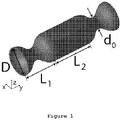
- the present invention relates to an apparatus for mixing based on oscillatory flow plate reactors provided with 2D smooth periodic constrictions.
- OFR is basically a column provided with periodic sharp constrictions, called baffles, operating under oscillatory flow mixing (OFM).
- the liquid or multiphase fluid is typically oscillated in the axial direction by means of diaphragms, bellows or pistons, at one or both ends of the tube, developing an efficient mixing mechanism where fluid moves from the walls to the centre of the tube with intensity controlled by the oscillation frequency (f) and amplitude (x 0 ).
- f oscillation frequency
- x 0 amplitude
- baffle thickness spacing and open area ( ⁇ ) defined as (orifice diameter (d 0 )/ tube diameter (D)) 2 , need to be selected and combined with a specific oscillation frequency and amplitude of the fluid.
- open area ( ⁇ ) are usually disclosed in percentage.
- Reis et al. [9] re-designed the conventional annular baffles presented at the conventional OFR in order to suit some of the bioprocess applications requirements.
- the disclosed geometry is based on Smooth Periodic Constrictions (SPCs).
- SPCs Smooth Periodic Constrictions
- the advantages associated with the use of the SPC geometry for a specific biotechnological process at mesoscale were demonstrated.
- the application of the SPC design, suggested by Reis et al. is restricted to one SPC geometry, two inner diameters (around 5 mm) and one system.
- the application of the SPC design, suggested by Reis et al. to others systems, such as crystallization, results in problems related with secondary nucleation, agglomeration and clogging, beyond others.
- the present invention fulfils the gaps identified in WO 2015/056156 , especially when solids are involved.
- the present invention relates to an improved apparatus for mixing intensification in multiphase systems, especially when solids are involved, which can be operating in continuous or batch mode.
- it relates to a plate reactor, which can be assembled and disassembled easily for cleaning.
- EP1767263 discloses a microchip and liquid mixing method.
- the present invention is defined by an apparatus for mixing intensification according to claim 1.
- the reactor vessel is build-up by stacking up at least two slices resulting in tubes with rectangular or square cross section (xOz section plane) rather than circle cross section.
- the reactor edges can be smoothed.
- the reactor vessel of the apparatus is provided with a at least two of inlets or outlets.
- the reactor vessel of the apparatus is in the form of a single plate reactor or at least two plate reactors, displaced in parallel, by stack up the plates.
- the reactor vessel of the apparatus is totally thermostatized.
- the jacket on the apparatus is used for mass transfer between the jacket and the reactor vessel or between the reactor vessel and the jacket.
- the mixing chamber of the apparatus is provided with at least two ports for inlet or outlet.
- the reactor vessel of the apparatus has the distance (L) between consecutive convergent sections 1 to 5 times the tube width (D w ) of the straight section.
- the reactor vessel of the apparatus has the convergent - divergent section length (L 1 ) 0.5 to 3 times the tube width (D w ) of the straight section.
- the reactor vessel of the apparatus has the shortest tube width (d 0w ) of the convergent - divergent section 0.1 to 0.5 times the tube width (D w ) of the straight section.
- the reactor vessel of the apparatus has the open area ( ⁇ ), defined as d 0w /D w , between 10 and 50%;
- the reactor vessel of the apparatus has the radius of curvature (R c ) of the sidewall of the convergent section 0.1 to 0.5 times the tube width (D w ) of the straight section.
- the reactor vessel of the apparatus has the radius of curvature (R d ) of the sidewall of the divergent section 0.1 to 0.5 times the tube width (D w ) of the straight section.
- the reactor vessel of the apparatus has the radius of curvature (R t ) at the convergent - divergent section centre of the reactor 0.1 to 0.5 times the tube width (D w ) of the straight section.
- the reactor vessel of the apparatus has the thickness ( ⁇ ) perpendicular to x0y plane 0.2 to 3 times the tube width (D w ) of the straight section.
- the present application also discloses the use of the apparatus in multiphase applications such as screening reactions, bioprocess, gas-liquid absorption, liquid-liquid extraction, precipitation and crystallization.
- the present application relates to an apparatus for mixing based on oscillatory flow plate reactors provided with 2D smooth periodic constrictions.
- This apparatus can be used in multiphase applications such as screening reactions, bioprocess, gas-liquid absorption, liquid-liquid extraction, precipitation and crystallization.
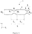
- the objective of the technology now disclosed is to provide an improved apparatus for mixing intensification in multiphase systems, especially the ones involving solids, which can be operated in continuous or batch mode. So, based on theoretical and experimental observations using different 2D-SPC geometries, as illustrated on Figures 2 and 3 , the present technology presents new dimensions' ranges that fulfil some of the gaps observed in WO 2015/056156 , especially when solids are involved.
- tube width (D w ) shortest tube width in the constrictions (d0 w ); thickness ( ⁇ ); mean spacing between consecutive constrictions (L 1 +L 2 ); constriction length (L 1 ); straight tube length (L 2 ); open area ( ⁇ ), defined as d 0w /D w , rather than (orifice diameter (d 0 )/ tube diameter (D)) 2 used in tubes with circle cross section; radius of curvature (R c ) of the sidewall of the convergent section (3); radius of curvature (R d ) of the sidewall of the divergent section (4); and, radius of curvature (R t ) at the convergent - divergent section (5) centre.
- the 2D-SPC geometries here disclosed decrease the problems related with solid handling, especially, solid deposition and fouling, identified in the OFRs presented by WO 2015/056156 [1], and increase its possible use in systems, for instance, in crystallization.
- OFPR-2D-SPC 2D Smooth Periodic Constrictions
- 2D-SPCs 2D Smooth Periodic Constrictions
- the OFPR-2D-SPC can be assembled and disassembled easily for cleaning.
- the plates can be arranged in parallel by stacking up the plates. This modular system permits the OFPR-2D-SPC use in most of the industrial applications.
- the plates are fully thermostatized and can be operated in batchwise or continuously.
- an oscillatory unit is used.
- the present application relates to an apparatus for mixing based on oscillatory flow plate reactors provided with 2D smooth periodic constrictions.
- the present technology comprises dimensions ranges that characterize the reactor vessel provided with 2D smooth periodic constrictions ( Figure 2 and 3 ), here defined as convergent - divergent section (5), and its arrangement in plates, as illustrated on Figures 4 .
- the said apparatus comprises a plate reactor provided with a reactor vessel (8) provided with smooth periodic constrictions (SPC), wherein the said smooth periodic constrictions (SPC) are present in two parallel faces of the rectangular or square cross section tube, characterizing the 2D smooth periodic constrictions; a mixing chamber (9); and oscillation means to oscillate the liquid or multiphase fluid within the reactor vessel.
- SPC smooth periodic constrictions
- the reactor vessel (8) may be made of metal, plastic, glass or any porous material.
- the reactor vessel (8) is characterized by a bundle of reactors (1), as illustrated on Figure 2 and 3 , that have alternatively straight sections (2) and convergent - divergent sections (5).
- Each convergent - divergent section (5) consists of a convergent section (3) and a divergent section (4).
- the convergent section (3) gradually reduces its tube width, and the divergent section (4) presents a gradually increasing the tube width.
- the shortest tube width, obtained at the junction of convergent section (3) and divergent section (4), is defined as d 0w .
- the tube width (D w ) of the straight section (2) is larger than d 0w .
- the convergent and divergent sections have a curved sidewall defined by the radius of curvature (R c ) of the sidewall of the convergent section (3), the radius of curvature (R d ) of the sidewall of the divergent section (4) and the radius of curvature (R t ) at the convergent - divergent section (5) centre.
- the reactor (1) fulfils the following conditions:
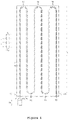
- the reactor vessel (8) characterized by a bundle of reactors (1) is incorporated in a plate reactor (6), as illustrated on Figures 4 .
- the plate reactor (6) comprises a continuous serpentine reactor vessel (8), characterized by a bundle of reactors (1), and an external tube used as jacket (7) for reactor vessel (8) thermostatization, or mass transfer, if reactor vessel (8) is made of porous material.
- the plate reactor (6) is build-up by stacking up at least two slices resulting in tubes with rectangular or square cross section (xOz section plane), rather than circle cross section presented in WO 2015/056156 [1], with a thickness perpendicular to x0y plane ( ⁇ ).
- the edges of the reactor vessel (8) can be smoothed.
- the jacket (7) has an inlet (12) and an outlet (13).
- This reactor vessel (8) has at least two inlets or outlets (14), to allow the addition of reactants or other substances, or sample collection.
- the plate reactor (6) can be arranged in parallel by stacking up the plates.
- the plate reactors (6) are connected by U tubes.
- the first plate reactor (6) is connected to an oscillatory unit (10), which induces a simple harmonic motion to the fluid in the reactor vessel (8), by a mixing chamber (9) provided with at least two inlets (11).
- Figure 4 shows a plan view of the oscillatory flow reactor apparatus based on plate reactor (6), constituted by an inner tube with rectangular or square cross section (xOz section plane), here defined as reactor vessel (8), presenting a bundle of reactors (1), an external tube used as jacket (7) for reactor vessel (8) thermostatization, or mass transfer if reactor vessel (8) is made of porous material, and at least two inlets or outlets (14), to allow the addition of reactants or other substances, or sample collection.
- reactor vessel (8) presenting a bundle of reactors (1), an external tube used as jacket (7) for reactor vessel (8) thermostatization, or mass transfer if reactor vessel (8) is made of porous material, and at least two inlets or outlets (14), to allow the addition of reactants or other substances, or sample collection.
- the plate reactors (6) can be closed using a close valve at reactor exit (15).
- the number, size and length of plate reactor (6) are designed according to the system specification.
- the plate reactors (6) can be operated in batchwise or continuously.
- the liquid or multiphase fluids are fed to the reactor vessel (8) through the inlets (11) of the mixing chamber (9).
- the liquid or multiphase fluid is oscillated in the axial direction by means of oscillatory unit (10), developing an efficient mixing mechanism where fluid moves from the walls to the centre of the tube with intensity controlled by the oscillation frequency (f) and amplitude (x 0 ).
- oscillation frequency (f) the oscillation frequency
- x 0 the oscillation frequency
- the formation and dissipation of eddies in the reactor results into significant enhancement in processes such as heat transfer, mass transfer, particle mixing and separation, beyond others.
- the reactor will obtain the optimum mixing conditions when:
- the disclosed technology can be used in mass and heat transfer intensification.
- the disclosed technology can be used in mixing intensification between liquid/liquid, liquid/gas and liquid/solid phases.
- the disclosed technology overcomes the disadvantages of the conventional OFR, based on annular baffles, especially in what concerns the dead zones decreasing and the quick cleaning process.
- the disclosed technology also overcomes the disadvantages of the meso-OFR based on SPC, especially in what concerns the decrease of the secondary nucleation, agglomeration and clogging problems.
- the present invention fulfils the gaps identified in WO 2015/056156 , especially when solids are involved, namely, solid deposition and fouling, when low oscillatory conditions need to be imposed.
- the disclosed technology relates to a plate reactor, which can be assembled and disassembled easily for cleaning.
- the disclosed technology can be operated in batchwise or continuously, this characteristic being of particular relevance in chemical, bio-chemical, biological and pharmaceutical industry.
- the disclosed technology offers unique features in comparison with conventional chemical reactors. It is suitable for multiphase applications such as screening reactions, bioprocess, gas-liquid absorption, precipitation and crystallization operating in batch or continuous mode.
Landscapes
- Chemical & Material Sciences (AREA)
- Chemical Kinetics & Catalysis (AREA)
- Organic Chemistry (AREA)
- Dispersion Chemistry (AREA)
- Physical Or Chemical Processes And Apparatus (AREA)
Claims (11)
- Vorrichtung, geeignet zur Mischintensivierung umfassend:- Einen Plattenreaktor (6) mit einem Reaktorbehälter (8), der mit glatten periodischen Einschnürungen (SPC) versehen ist, wobei der Reaktorbehälter (8) ein Bündel von Reaktoren (1) umfasst, die abwechselnd gerade Abschnitte (2) und konvergente-divergente Abschnitte (5) aufweisen, wobei jeder konvergente-divergente Abschnitt (5) aus einem konvergenten Abschnitt (3) und einem divergenten Abschnitt (4) besteht, wobei der Abstand L zwischen aufeinanderfolgenden konvergenten Abschnitten definiert ist durch:eine Länge L2 des geraden Abschnitts (2) mit einer Breite Dw und eine Länge L1 des konvergent-divergenten Abschnitts (5); wobei die genannte Länge L1 einen Krümmungsradius Rc einer Seitenwand des konvergenten Abschnitts (3), einen Krümmungsradius Rd einer Seitenwand des divergenten Abschnitts (4) und einen Krümmungsradius Rt an der Mitte des konvergenten-divergenten Abschnitts umfasst;wobei die genannte Länge L1 ferner einen offenen Bereich α umfasst, der als die kürzeste Rohrbreite d0w des konvergenten-divergenten Abschnitts (5) definiert ist, geteilt durch die Breite Dw, wobei:- der Abstand L das 1- bis 5-fache der Breite Dw beträgt;- L1 das 0,5- bis 3-fache der Breite Dw beträgt;- die Breite d0w des konvergent-divergenten Abschnitts (5) 0,1- bis 0,5-mal so groß wie die Breite Dw ist;- Rc das 0,1- bis 0,5-fache der Breite Dw ist;- Rd das 0,1- bis 0,5-fache der Breite Dw ist;- Rt das 0,1- bis 0,5-fache der Breite Dw ist;- der offene Bereich α Werte zwischen 10 und 50 % hat; wobei die genannten glatten periodischen Einschnürungen (SPC) in zwei parallelen Flächen eines Rohrs mit rechteckigem oder quadratischem Querschnitt vorhanden sind, die die 2D glatten periodischen Einschnürungen (SPC) definieren;- Eine Mischkammer (9);- Oszillationsmittel, um ein flüssiges oder mehrphasiges Fluid innerhalb des Reaktorbehälters (8) zu oszillieren.
- Vorrichtung nach dem vorhergehenden Anspruch, wobei der Plattenreaktor (6) durch Stapeln von zwei oder mehr Scheiben aufgebaut ist, was zu Rohren mit rechteckigem oder quadratischem Querschnitt führt.
- Vorrichtung nach einem der vorhergehenden Ansprüche, wobei der Reaktorbehälter (8) mit glatten Kanten versehen ist.
- Vorrichtung nach einem der vorhergehenden Ansprüche, wobei der Reaktorbehälter (8) mit mindestens zwei Einlässen oder Auslässen (14) versehen ist.
- Vorrichtung nach einem der vorhergehenden Ansprüche, wobei die Reaktorplatte (6) zusammensetzbar und auseinandernehmbar ist.
- Vorrichtung nach einem der vorhergehenden Ansprüche, wobei der Reaktorbehälter (8) die Form eines einzelnen Plattenreaktors (6) oder mindestens zweier Plattenreaktoren (6) hat, die durch Aufeinanderstapeln der Platten parallel verschoben sind.
- Vorrichtung nach einem der vorhergehenden Ansprüche, wobei der Reaktorbehälter (8) vollständig thermostatisiert ist.
- Vorrichtung nach einem der vorhergehenden Ansprüche, wobei die Vorrichtung einen Mantel (7) umfasst.
- Vorrichtung nach einem der vorhergehenden Ansprüche, wobei die Mischkammer (9) mit mindestens zwei Einlass- oder Auslassöffnungen (11) versehen ist.
- Vorrichtung nach einem der vorhergehenden Ansprüche, wobei die Dicke senkrecht zur x0y-Ebene (ω) das 0,2- bis 3-fache der Rohrbreite (Dw) des geraden Abschnitts (2) beträgt.
- Verwendung der in einem der vorhergehenden Ansprüche offenbarten Vorrichtung bei Mehrphasenanwendungen wie Screening-Reaktionen, Bioprozessen, Gas-Flüssig-Absorption, Flüssig-Flüssig-Extraktion, Ausfällung und Kristallisation.
Applications Claiming Priority (2)
| Application Number | Priority Date | Filing Date | Title |
|---|---|---|---|
| PT10931416 | 2016-04-08 | ||
| PCT/IB2017/052064 WO2017175207A1 (en) | 2016-04-08 | 2017-04-10 | Modular oscillatory flow plate reactor |
Publications (2)
| Publication Number | Publication Date |
|---|---|
| EP3439773A1 EP3439773A1 (de) | 2019-02-13 |
| EP3439773B1 true EP3439773B1 (de) | 2022-11-09 |
Family
ID=58737693
Family Applications (1)
| Application Number | Title | Priority Date | Filing Date |
|---|---|---|---|
| EP17724445.6A Active EP3439773B1 (de) | 2016-04-08 | 2017-04-10 | Modularer oszillierender strömungsplattenreaktor |
Country Status (3)
| Country | Link |
|---|---|
| US (1) | US20190111402A1 (de) |
| EP (1) | EP3439773B1 (de) |
| WO (1) | WO2017175207A1 (de) |
Families Citing this family (1)
| Publication number | Priority date | Publication date | Assignee | Title |
|---|---|---|---|---|
| BE1026312B1 (nl) | 2018-05-25 | 2019-12-23 | Ajinomoto Omnichem | Doorstroomreactor en gebruik ervan |
Family Cites Families (8)
| Publication number | Priority date | Publication date | Assignee | Title |
|---|---|---|---|---|
| GB9306472D0 (en) | 1993-03-29 | 1993-05-19 | Mackley Malcolm R | Improvements in or relating to the processing of mixtures |
| US6270641B1 (en) * | 1999-04-26 | 2001-08-07 | Sandia Corporation | Method and apparatus for reducing sample dispersion in turns and junctions of microchannel systems |
| EP2281633A1 (de) * | 2001-08-28 | 2011-02-09 | Gyros Patent Ab | Mikrokammern und mikrofluidische Strukturen zur Handhabung kleiner Flüssigkeitsmengen |
| PT103072B (pt) | 2004-02-13 | 2009-12-02 | Faculdade De Engenharia Da Uni | Misturador em rede e respectivo processo de mistura |
| JP2007121275A (ja) * | 2005-09-27 | 2007-05-17 | Fujifilm Corp | マイクロチップ、このマイクロチップを用いた液体の混合方法及び血液検査方法 |
| DE102007039713A1 (de) * | 2006-08-22 | 2008-02-28 | Friedrich-Alexander-Universität Erlangen-Nürnberg | Mischvorrichtung |
| DE602007013010D1 (de) * | 2007-05-15 | 2011-04-21 | Corning Inc | Mikrofluidische und selbstverzögernde oszillierende Mischer sowie Vorrichtungen und Verfahren zu deren Verwendung |
| PT3057694T (pt) | 2013-10-14 | 2019-07-30 | Univ Do Porto | Aparelho para mistura com base em reatores de fluxo oscilatório munidos de constrições periódicas suaves |
-
2017
- 2017-04-10 WO PCT/IB2017/052064 patent/WO2017175207A1/en active Application Filing
- 2017-04-10 EP EP17724445.6A patent/EP3439773B1/de active Active
- 2017-04-10 US US16/092,010 patent/US20190111402A1/en not_active Abandoned
Also Published As
| Publication number | Publication date |
|---|---|
| WO2017175207A1 (en) | 2017-10-12 |
| EP3439773A1 (de) | 2019-02-13 |
| US20190111402A1 (en) | 2019-04-18 |
Similar Documents
| Publication | Publication Date | Title |
|---|---|---|
| EP3057694B1 (de) | Vorrichtung zum mischen auf der basis von oszillierenden strömungsreaktoren mit glatten periodischen verengungen | |
| US10118149B2 (en) | Oscillating flow minireactor | |
| McDonough et al. | Rapid process development using oscillatory baffled mesoreactors–A state-of-the-art review | |
| Ni et al. | Mixing through oscillations and pulsations—a guide to achieving process enhancements in the chemical and process industries | |
| EP0489211B1 (de) | Jetaufprallreaktor | |
| Li et al. | Intensification of liquid–liquid two‐phase mass transfer in a capillary microreactor system | |
| MX2010000485A (es) | Dispositivos microfluidicos de proceso intesificado. | |
| CN102802779B (zh) | 微型反应器 | |
| US10632449B2 (en) | Method of mixing using an improved flow reactor | |
| EP3439773B1 (de) | Modularer oszillierender strömungsplattenreaktor | |
| WO2006092360A1 (en) | Oscillatory flow mixing reactor | |
| CN113893796A (zh) | 一种链式微反应器 | |
| WO2016001791A1 (en) | Baffle assembly for a reactor | |
| CN108355595A (zh) | 微波催化连续管道反应器 | |
| KR200496561Y1 (ko) | 네트워크 열 교환기 장치, 그 방법 및 용도 | |
| CN109622080B (zh) | 用于多指标分析的微液滴生成芯片 | |
| CN108325483B (zh) | 微孔涡流套管反应器及其应用 | |
| Bayer et al. | Mixing and organic chemistry | |
| RU116366U1 (ru) | Статический смеситель | |
| CN210496444U (zh) | 一种填料组件和包含它的管道式反应器 | |
| US20220410116A1 (en) | A continuous flow reactor | |
| RU2759628C1 (ru) | Статический смеситель для дробления пузырьков газа в газожидкостной смеси | |
| RU2753756C1 (ru) | Аппарат для проведения массообменных и реакционных процессов в однофазных и многофазных средах | |
| McDonough | Process development using oscillatory baffled mesoreactors | |
| US20220241740A1 (en) | Mixing device with reversed coiled configuration and use thereof |
Legal Events
| Date | Code | Title | Description |
|---|---|---|---|
| STAA | Information on the status of an ep patent application or granted ep patent |
Free format text: STATUS: UNKNOWN |
|
| STAA | Information on the status of an ep patent application or granted ep patent |
Free format text: STATUS: THE INTERNATIONAL PUBLICATION HAS BEEN MADE |
|
| PUAI | Public reference made under article 153(3) epc to a published international application that has entered the european phase |
Free format text: ORIGINAL CODE: 0009012 |
|
| STAA | Information on the status of an ep patent application or granted ep patent |
Free format text: STATUS: REQUEST FOR EXAMINATION WAS MADE |
|
| 17P | Request for examination filed |
Effective date: 20181108 |
|
| AK | Designated contracting states |
Kind code of ref document: A1 Designated state(s): AL AT BE BG CH CY CZ DE DK EE ES FI FR GB GR HR HU IE IS IT LI LT LU LV MC MK MT NL NO PL PT RO RS SE SI SK SM TR |
|
| AX | Request for extension of the european patent |
Extension state: BA ME |
|
| STAA | Information on the status of an ep patent application or granted ep patent |
Free format text: STATUS: REQUEST FOR EXAMINATION WAS MADE |
|
| DAV | Request for validation of the european patent (deleted) | ||
| DAX | Request for extension of the european patent (deleted) | ||
| STAA | Information on the status of an ep patent application or granted ep patent |
Free format text: STATUS: EXAMINATION IS IN PROGRESS |
|
| 17Q | First examination report despatched |
Effective date: 20210205 |
|
| STAA | Information on the status of an ep patent application or granted ep patent |
Free format text: STATUS: EXAMINATION IS IN PROGRESS |
|
| REG | Reference to a national code |
Ref country code: DE Ref legal event code: R079 Ref document number: 602017063511 Country of ref document: DE Free format text: PREVIOUS MAIN CLASS: B01F0005060000 Ipc: B01F0025433000 |
|
| GRAP | Despatch of communication of intention to grant a patent |
Free format text: ORIGINAL CODE: EPIDOSNIGR1 |
|
| STAA | Information on the status of an ep patent application or granted ep patent |
Free format text: STATUS: GRANT OF PATENT IS INTENDED |
|
| RIC1 | Information provided on ipc code assigned before grant |
Ipc: B01J 19/24 20060101ALI20220627BHEP Ipc: B01F 35/92 20220101ALI20220627BHEP Ipc: B01F 31/65 20220101ALI20220627BHEP Ipc: B01F 25/433 20220101AFI20220627BHEP |
|
| INTG | Intention to grant announced |
Effective date: 20220711 |
|
| GRAS | Grant fee paid |
Free format text: ORIGINAL CODE: EPIDOSNIGR3 |
|
| GRAA | (expected) grant |
Free format text: ORIGINAL CODE: 0009210 |
|
| STAA | Information on the status of an ep patent application or granted ep patent |
Free format text: STATUS: THE PATENT HAS BEEN GRANTED |
|
| AK | Designated contracting states |
Kind code of ref document: B1 Designated state(s): AL AT BE BG CH CY CZ DE DK EE ES FI FR GB GR HR HU IE IS IT LI LT LU LV MC MK MT NL NO PL PT RO RS SE SI SK SM TR |
|
| REG | Reference to a national code |
Ref country code: GB Ref legal event code: FG4D |
|
| REG | Reference to a national code |
Ref country code: CH Ref legal event code: EP Ref country code: AT Ref legal event code: REF Ref document number: 1529994 Country of ref document: AT Kind code of ref document: T Effective date: 20221115 |
|
| REG | Reference to a national code |
Ref country code: DE Ref legal event code: R096 Ref document number: 602017063511 Country of ref document: DE |
|
| REG | Reference to a national code |
Ref country code: IE Ref legal event code: FG4D |
|
| REG | Reference to a national code |
Ref country code: PT Ref legal event code: SC4A Ref document number: 3439773 Country of ref document: PT Date of ref document: 20230125 Kind code of ref document: T Free format text: AVAILABILITY OF NATIONAL TRANSLATION Effective date: 20230119 |
|
| REG | Reference to a national code |
Ref country code: LT Ref legal event code: MG9D |
|
| REG | Reference to a national code |
Ref country code: NL Ref legal event code: MP Effective date: 20221109 |
|
| REG | Reference to a national code |
Ref country code: AT Ref legal event code: MK05 Ref document number: 1529994 Country of ref document: AT Kind code of ref document: T Effective date: 20221109 |
|
| PG25 | Lapsed in a contracting state [announced via postgrant information from national office to epo] |
Ref country code: SE Free format text: LAPSE BECAUSE OF FAILURE TO SUBMIT A TRANSLATION OF THE DESCRIPTION OR TO PAY THE FEE WITHIN THE PRESCRIBED TIME-LIMIT Effective date: 20221109 Ref country code: NO Free format text: LAPSE BECAUSE OF FAILURE TO SUBMIT A TRANSLATION OF THE DESCRIPTION OR TO PAY THE FEE WITHIN THE PRESCRIBED TIME-LIMIT Effective date: 20230209 Ref country code: LT Free format text: LAPSE BECAUSE OF FAILURE TO SUBMIT A TRANSLATION OF THE DESCRIPTION OR TO PAY THE FEE WITHIN THE PRESCRIBED TIME-LIMIT Effective date: 20221109 Ref country code: FI Free format text: LAPSE BECAUSE OF FAILURE TO SUBMIT A TRANSLATION OF THE DESCRIPTION OR TO PAY THE FEE WITHIN THE PRESCRIBED TIME-LIMIT Effective date: 20221109 Ref country code: ES Free format text: LAPSE BECAUSE OF FAILURE TO SUBMIT A TRANSLATION OF THE DESCRIPTION OR TO PAY THE FEE WITHIN THE PRESCRIBED TIME-LIMIT Effective date: 20221109 Ref country code: AT Free format text: LAPSE BECAUSE OF FAILURE TO SUBMIT A TRANSLATION OF THE DESCRIPTION OR TO PAY THE FEE WITHIN THE PRESCRIBED TIME-LIMIT Effective date: 20221109 |
|
| PG25 | Lapsed in a contracting state [announced via postgrant information from national office to epo] |
Ref country code: RS Free format text: LAPSE BECAUSE OF FAILURE TO SUBMIT A TRANSLATION OF THE DESCRIPTION OR TO PAY THE FEE WITHIN THE PRESCRIBED TIME-LIMIT Effective date: 20221109 Ref country code: PL Free format text: LAPSE BECAUSE OF FAILURE TO SUBMIT A TRANSLATION OF THE DESCRIPTION OR TO PAY THE FEE WITHIN THE PRESCRIBED TIME-LIMIT Effective date: 20221109 Ref country code: LV Free format text: LAPSE BECAUSE OF FAILURE TO SUBMIT A TRANSLATION OF THE DESCRIPTION OR TO PAY THE FEE WITHIN THE PRESCRIBED TIME-LIMIT Effective date: 20221109 Ref country code: IS Free format text: LAPSE BECAUSE OF FAILURE TO SUBMIT A TRANSLATION OF THE DESCRIPTION OR TO PAY THE FEE WITHIN THE PRESCRIBED TIME-LIMIT Effective date: 20230309 Ref country code: HR Free format text: LAPSE BECAUSE OF FAILURE TO SUBMIT A TRANSLATION OF THE DESCRIPTION OR TO PAY THE FEE WITHIN THE PRESCRIBED TIME-LIMIT Effective date: 20221109 Ref country code: GR Free format text: LAPSE BECAUSE OF FAILURE TO SUBMIT A TRANSLATION OF THE DESCRIPTION OR TO PAY THE FEE WITHIN THE PRESCRIBED TIME-LIMIT Effective date: 20230210 |
|
| PG25 | Lapsed in a contracting state [announced via postgrant information from national office to epo] |
Ref country code: NL Free format text: LAPSE BECAUSE OF FAILURE TO SUBMIT A TRANSLATION OF THE DESCRIPTION OR TO PAY THE FEE WITHIN THE PRESCRIBED TIME-LIMIT Effective date: 20221109 |
|
| PG25 | Lapsed in a contracting state [announced via postgrant information from national office to epo] |
Ref country code: SM Free format text: LAPSE BECAUSE OF FAILURE TO SUBMIT A TRANSLATION OF THE DESCRIPTION OR TO PAY THE FEE WITHIN THE PRESCRIBED TIME-LIMIT Effective date: 20221109 Ref country code: RO Free format text: LAPSE BECAUSE OF FAILURE TO SUBMIT A TRANSLATION OF THE DESCRIPTION OR TO PAY THE FEE WITHIN THE PRESCRIBED TIME-LIMIT Effective date: 20221109 Ref country code: EE Free format text: LAPSE BECAUSE OF FAILURE TO SUBMIT A TRANSLATION OF THE DESCRIPTION OR TO PAY THE FEE WITHIN THE PRESCRIBED TIME-LIMIT Effective date: 20221109 Ref country code: DK Free format text: LAPSE BECAUSE OF FAILURE TO SUBMIT A TRANSLATION OF THE DESCRIPTION OR TO PAY THE FEE WITHIN THE PRESCRIBED TIME-LIMIT Effective date: 20221109 Ref country code: CZ Free format text: LAPSE BECAUSE OF FAILURE TO SUBMIT A TRANSLATION OF THE DESCRIPTION OR TO PAY THE FEE WITHIN THE PRESCRIBED TIME-LIMIT Effective date: 20221109 |
|
| PGFP | Annual fee paid to national office [announced via postgrant information from national office to epo] |
Ref country code: DE Payment date: 20230404 Year of fee payment: 7 |
|
| REG | Reference to a national code |
Ref country code: DE Ref legal event code: R097 Ref document number: 602017063511 Country of ref document: DE |
|
| PG25 | Lapsed in a contracting state [announced via postgrant information from national office to epo] |
Ref country code: SK Free format text: LAPSE BECAUSE OF FAILURE TO SUBMIT A TRANSLATION OF THE DESCRIPTION OR TO PAY THE FEE WITHIN THE PRESCRIBED TIME-LIMIT Effective date: 20221109 Ref country code: AL Free format text: LAPSE BECAUSE OF FAILURE TO SUBMIT A TRANSLATION OF THE DESCRIPTION OR TO PAY THE FEE WITHIN THE PRESCRIBED TIME-LIMIT Effective date: 20221109 |
|
| PLBE | No opposition filed within time limit |
Free format text: ORIGINAL CODE: 0009261 |
|
| STAA | Information on the status of an ep patent application or granted ep patent |
Free format text: STATUS: NO OPPOSITION FILED WITHIN TIME LIMIT |
|
| 26N | No opposition filed |
Effective date: 20230810 |
|
| PG25 | Lapsed in a contracting state [announced via postgrant information from national office to epo] |
Ref country code: SI Free format text: LAPSE BECAUSE OF FAILURE TO SUBMIT A TRANSLATION OF THE DESCRIPTION OR TO PAY THE FEE WITHIN THE PRESCRIBED TIME-LIMIT Effective date: 20221109 |
|
| REG | Reference to a national code |
Ref country code: CH Ref legal event code: PL |
|
| GBPC | Gb: european patent ceased through non-payment of renewal fee |
Effective date: 20230410 |
|
| PG25 | Lapsed in a contracting state [announced via postgrant information from national office to epo] |
Ref country code: LU Free format text: LAPSE BECAUSE OF NON-PAYMENT OF DUE FEES Effective date: 20230410 |
|
| REG | Reference to a national code |
Ref country code: BE Ref legal event code: MM Effective date: 20230430 |
|
| PG25 | Lapsed in a contracting state [announced via postgrant information from national office to epo] |
Ref country code: MC Free format text: LAPSE BECAUSE OF FAILURE TO SUBMIT A TRANSLATION OF THE DESCRIPTION OR TO PAY THE FEE WITHIN THE PRESCRIBED TIME-LIMIT Effective date: 20221109 |
|
| PG25 | Lapsed in a contracting state [announced via postgrant information from national office to epo] |
Ref country code: GB Free format text: LAPSE BECAUSE OF NON-PAYMENT OF DUE FEES Effective date: 20230410 |
|
| PG25 | Lapsed in a contracting state [announced via postgrant information from national office to epo] |
Ref country code: MC Free format text: LAPSE BECAUSE OF FAILURE TO SUBMIT A TRANSLATION OF THE DESCRIPTION OR TO PAY THE FEE WITHIN THE PRESCRIBED TIME-LIMIT Effective date: 20221109 Ref country code: LI Free format text: LAPSE BECAUSE OF NON-PAYMENT OF DUE FEES Effective date: 20230430 Ref country code: GB Free format text: LAPSE BECAUSE OF NON-PAYMENT OF DUE FEES Effective date: 20230410 Ref country code: FR Free format text: LAPSE BECAUSE OF NON-PAYMENT OF DUE FEES Effective date: 20230430 Ref country code: CH Free format text: LAPSE BECAUSE OF NON-PAYMENT OF DUE FEES Effective date: 20230430 |
|
| PGFP | Annual fee paid to national office [announced via postgrant information from national office to epo] |
Ref country code: PT Payment date: 20231201 Year of fee payment: 8 |
|
| REG | Reference to a national code |
Ref country code: IE Ref legal event code: MM4A |
|
| PG25 | Lapsed in a contracting state [announced via postgrant information from national office to epo] |
Ref country code: BE Free format text: LAPSE BECAUSE OF NON-PAYMENT OF DUE FEES Effective date: 20230430 |
|
| PG25 | Lapsed in a contracting state [announced via postgrant information from national office to epo] |
Ref country code: IE Free format text: LAPSE BECAUSE OF NON-PAYMENT OF DUE FEES Effective date: 20230410 |
|
| PG25 | Lapsed in a contracting state [announced via postgrant information from national office to epo] |
Ref country code: IE Free format text: LAPSE BECAUSE OF NON-PAYMENT OF DUE FEES Effective date: 20230410 |