EP3439566B1 - Knochenimplantat mit versatz im injektionskanal sowie implantationswerkzeug hierfür - Google Patents
Knochenimplantat mit versatz im injektionskanal sowie implantationswerkzeug hierfür Download PDFInfo
- Publication number
- EP3439566B1 EP3439566B1 EP17716162.7A EP17716162A EP3439566B1 EP 3439566 B1 EP3439566 B1 EP 3439566B1 EP 17716162 A EP17716162 A EP 17716162A EP 3439566 B1 EP3439566 B1 EP 3439566B1
- Authority
- EP
- European Patent Office
- Prior art keywords
- bone
- injection
- wall
- implant
- implantation
- Prior art date
- Legal status (The legal status is an assumption and is not a legal conclusion. Google has not performed a legal analysis and makes no representation as to the accuracy of the status listed.)
- Active
Links
Images


Classifications
-
- A—HUMAN NECESSITIES
- A61—MEDICAL OR VETERINARY SCIENCE; HYGIENE
- A61B—DIAGNOSIS; SURGERY; IDENTIFICATION
- A61B17/00—Surgical instruments, devices or methods
- A61B17/56—Surgical instruments or methods for treatment of bones or joints; Devices specially adapted therefor
- A61B17/58—Surgical instruments or methods for treatment of bones or joints; Devices specially adapted therefor for osteosynthesis, e.g. bone plates, screws or setting implements
- A61B17/88—Osteosynthesis instruments; Methods or means for implanting or extracting internal or external fixation devices
- A61B17/8802—Equipment for handling bone cement or other fluid fillers
- A61B17/8841—Tools specially adapted to engage a prosthesis
-
- A—HUMAN NECESSITIES
- A61—MEDICAL OR VETERINARY SCIENCE; HYGIENE
- A61B—DIAGNOSIS; SURGERY; IDENTIFICATION
- A61B17/00—Surgical instruments, devices or methods
- A61B17/56—Surgical instruments or methods for treatment of bones or joints; Devices specially adapted therefor
- A61B17/58—Surgical instruments or methods for treatment of bones or joints; Devices specially adapted therefor for osteosynthesis, e.g. bone plates, screws or setting implements
- A61B17/68—Internal fixation devices, including fasteners and spinal fixators, even if a part thereof projects from the skin
- A61B17/84—Fasteners therefor or fasteners being internal fixation devices
- A61B17/86—Pins or screws or threaded wires; nuts therefor
- A61B17/8625—Shanks, i.e. parts contacting bone tissue
-
- A—HUMAN NECESSITIES
- A61—MEDICAL OR VETERINARY SCIENCE; HYGIENE
- A61B—DIAGNOSIS; SURGERY; IDENTIFICATION
- A61B17/00—Surgical instruments, devices or methods
- A61B17/56—Surgical instruments or methods for treatment of bones or joints; Devices specially adapted therefor
- A61B17/58—Surgical instruments or methods for treatment of bones or joints; Devices specially adapted therefor for osteosynthesis, e.g. bone plates, screws or setting implements
- A61B17/68—Internal fixation devices, including fasteners and spinal fixators, even if a part thereof projects from the skin
- A61B17/84—Fasteners therefor or fasteners being internal fixation devices
- A61B17/86—Pins or screws or threaded wires; nuts therefor
- A61B17/864—Pins or screws or threaded wires; nuts therefor hollow, e.g. with socket or cannulated
-
- A—HUMAN NECESSITIES
- A61—MEDICAL OR VETERINARY SCIENCE; HYGIENE
- A61B—DIAGNOSIS; SURGERY; IDENTIFICATION
- A61B17/00—Surgical instruments, devices or methods
- A61B17/56—Surgical instruments or methods for treatment of bones or joints; Devices specially adapted therefor
- A61B17/58—Surgical instruments or methods for treatment of bones or joints; Devices specially adapted therefor for osteosynthesis, e.g. bone plates, screws or setting implements
- A61B17/88—Osteosynthesis instruments; Methods or means for implanting or extracting internal or external fixation devices
- A61B17/8802—Equipment for handling bone cement or other fluid fillers
- A61B17/8805—Equipment for handling bone cement or other fluid fillers for introducing fluid filler into bone or extracting it
-
- A—HUMAN NECESSITIES
- A61—MEDICAL OR VETERINARY SCIENCE; HYGIENE
- A61B—DIAGNOSIS; SURGERY; IDENTIFICATION
- A61B17/00—Surgical instruments, devices or methods
- A61B17/56—Surgical instruments or methods for treatment of bones or joints; Devices specially adapted therefor
- A61B17/58—Surgical instruments or methods for treatment of bones or joints; Devices specially adapted therefor for osteosynthesis, e.g. bone plates, screws or setting implements
- A61B17/68—Internal fixation devices, including fasteners and spinal fixators, even if a part thereof projects from the skin
- A61B17/70—Spinal positioners or stabilisers, e.g. stabilisers comprising fluid filler in an implant
- A61B17/7001—Screws or hooks combined with longitudinal elements which do not contact vertebrae
Definitions
- the present invention relates to a bone implant with an implant shaft for placement in a bone and an implant head arranged proximally on the implant shaft with a tool holder for an implantation tool, wherein the implant shaft has a longitudinal axis A and a continuous injection channel for injecting a bone bonding material is formed in the implant shaft, which has a proximal inlet opening for the bone bonding material on the side of the tool holder.
- the invention further relates to an implantation instrument for a bone implant according to one of the preceding claims, which has an injection cannula with an inner channel with a longitudinal axis B for injecting bone bonding material.
- an implantation system with a bone implant according to the invention and an implantation instrument according to the invention.
- Bone implants such as joint prostheses, bone or pedicle screws, are known from the state of the art. They are inserted into a bone and secured there. They can be secured, for example, by screwing in and alternatively or additionally by means of a bone bonding compound or a bone bonding material, also known as bone cement.
- a bone implant has at least one channel, also known as an injection channel or cement channel, through which the bone bonding compound/material can be introduced and placed in the desired manner and at the desired location during implantation.
- Pedicle screws are used, for example, for dorsal stabilization of the spine using transpedicular screwing.
- Pedicle screws are placed in the pedicles of adjacent vertebrae, whereupon an angle-stable connection is created between the pedicle screws arranged axially one above the other and an axially extending longitudinal beam or bar.
- the longitudinal beam is inserted into a receiving sleeve on the screw head side, the so-called tulip, and clamped there. In this way, the pedicle screws and the longitudinal beam form a vertebral stabilization system.
- part of the hardened cement can be pulled out of the pedicle screw and/or the augmentation cannula and break in such a way that a cement column protrudes from the pedicle screw. This can make further surgical steps difficult or even impossible. An unnoticed detachment of parts or sections of such a cement column represents a significant risk to the well-being, health or life of the patient.
- An implant e.g. in the form of a polyaxial screw with a screw shaft and a longitudinal channel formed therein, as well as a medical instrument for implanting it are known, wherein the instrument has a tool section with a first tool element for engaging with a corresponding second tool element in the implant, wherein a bone cement container is formed or arranged on or in the instrument.
- a distal end of the screw shaft is open and is in fluid communication with the longitudinal channel.
- the proximal end of the screw shaft is formed in the form of a spherical head on which a sleeve is articulated.
- the proximal end of the longitudinal channel opens into the ball head.
- the instrument and the implant are brought into engagement using the two tool elements, which creates a fluid connection between the bone cement container and the longitudinal channel.
- a similar implant is known with a tool holder for connecting to an implantation tool and with a connecting device for connecting the implant to an injection cannula for injecting a bone connection material, wherein the connecting device comprises an internal thread portion which is formed in or on the tool holder.
- a pedicle screw which has been cannulated and provided with lateral holes or millings, allowing complete or partial closure of the cannulation at the distal end of the screw.
- a pedicle screw which is provided with an internal channel and openings in the screw shaft and in the threaded section.
- An internal thread is formed in a head of the pedicle screw for connecting the screw to an injection cannula for applying bone cement.
- a bone anchor with a screw-like bone engagement portion and an elongated guide portion for guiding a device for engagement with the bone engagement portion is known.
- the bone engagement portion comprises a cannula passage.
- a proximal portion of the bone engagement portion can be provided with an internal thread for fastening the guide portion and a further internal thread can be defined in the proximal head of the bone engagement portion, which is suitable for engagement with the device.
- the US 2014/194886 A1 discloses another example of an implantation system with an implantation and injection instrument for and with a bone implant in the form of a pedicle screw.
- US 7 338 493 B1 a bone screw anchor capable of securely attaching a fixation device to weak or fragile bone.
- the anchor has a proximal portion that includes a receptacle for a driver that drives the anchor into a bore or hole in the bone.
- the anchor has an internally threaded bore to receive a bone screw that is used to attach a fixation device to the anchor. Bone cement can be placed into the bore.
- the invention is based on the object of creating a bone implant and a bone implantation system that does not have the above disadvantages.
- the leakage or even detachment of bone connecting material from the implant and from the medical instrument used for application should be reliably prevented.
- the bone implant and the bone implantation system should be easy and safe to handle and inexpensive.
- the object is achieved by an implantation instrument according to claim 1, an implantation system according to claim 7 and/or a bone implant in the form of a pedicle screw according to claim 14.
- an implantation instrument for a bone implant preferably in the form of a pedicle screw, comprising an injection cannula with an inner channel with a longitudinal axis B for injecting Bone bonding material, wherein the inner channel has a distal outlet opening for bone bonding material and has a predetermined inner channel diameter there, wherein the wall of the injection cannula surrounding the inner channel has a radial offset to the longitudinal axis B starting from the distal outlet opening, preferably a thread introduced into the wall of the inner channel or a groove introduced into the wall of the inner channel, which extends radially outward relative to the predetermined inner channel diameter formed both distally and proximally to the offset, wherein the radial offset is formed at least in a region of the wall which is spaced from the distal outlet opening between approximately 0.5 mm and approximately 10 mm.
- the radial offset is formed in a region of the wall which, with respect to the injection cannula, is located near the distal outlet opening or on the side of the distal outlet opening. It can also be said that the radial offset is formed in a section of the channel wall adjacent to the distal outlet opening.
- the radial offset is spaced from the distal outlet opening by at least approximately 0.5 mm and a maximum of approximately 10 mm, and can assume any value in between. According to one embodiment, it can be spaced from the distal outlet opening by between approximately 1 mm and approximately 7.5 mm, according to another form, between approximately 1.5 mm and approximately 5 mm, and according to another embodiment, between approximately 2 mm and approximately 3 mm.
- an implantation system with an implantation instrument for a bone implant preferably in the form of a pedicle screw, having an injection cannula with an inner channel with a longitudinal axis B for injecting bone bonding material, wherein the inner channel has a distal outlet opening for bone bonding material and has a predetermined inner channel diameter there, wherein the wall of the injection cannula surrounding the inner channel has a radial offset to the longitudinal axis B starting from the distal outlet opening, preferably has a thread introduced into the wall of the inner channel or a groove introduced into the wall of the inner channel, which is opposite the predetermined inner channel diameter, which is both distal and proximal to the offset forms, extends radially outwards, preferably an implantation instrument as described above, and a bone implant with a distal implant shaft which is designed to be sunk into a bone, and a proximal implant head with a tool holder for an implantation tool, from which an injection channel for injecting
- the object is achieved by a bone implant in the form of a pedicle screw for an implantation system described above, with a distal implant shaft which is designed to be sunk into a bone, and a proximal implant head with a tool holder for an implantation tool, from which an injection channel for injecting a bone bonding material extends into the implant shaft and has a predetermined injection channel diameter there, wherein the wall surrounding the injection channel has an offset starting from the tool holder in the form of a singular groove introduced into the wall of the injection channel, which extends radially outward relative to the predetermined injection channel diameter which is formed proximally and distally to the offset, wherein the singular groove is formed by a single undercut introduced into the wall of the injection channel.
- the wall of the implant shaft surrounding the injection channel has a radial offset to the longitudinal axis A on the side of the proximal inlet opening.
- An implantation instrument according to claim 1 for a bone implant has an injection cannula with an inner channel with a longitudinal axis B for injecting bone bonding material, wherein the inner channel has a distal outlet opening for bone bonding material wherein the wall of the injection cannula surrounding the inner channel has a radial offset to the longitudinal axis B on the side of the distal outlet opening.
- An implantation system according to claim 7 has a bone implant and an implantation instrument according to the invention.
- a bone implant is proposed, with a distal implant shaft, which is designed to be sunk into a bone, and a proximal implant head with a tool holder for an implantation tool, from which an injection channel for injecting a bone bonding material extends into the implant shaft and has a predetermined injection channel diameter there, wherein the wall surrounding the injection channel has an offset, starting from the tool holder, preferably a thread introduced into the wall of the injection channel or a groove introduced into the wall of the injection channel, which extends proximally and distally to the offset radially outward relative to the predetermined injection channel diameter
- an implantation instrument for a bone implant according to the invention comprising an injection cannula with an inner channel with a longitudinal axis B for injecting bone bonding material, wherein the inner channel has a distal outlet opening for bone bonding material and has a predetermined inner channel diameter there, wherein the wall of the injection cannula surrounding the inner channel has a Longitudinal
- the invention discloses a friction-increasing element at a proximal end of a bone implant or at the distal end of an implantation tool, which is triggered by means of the above-described offset, a proximal movement of the bone connection material. by removing the implantation tool by the surgeon, and thus ensures a predetermined breaking point for the bone connection material before / during its complete hardening.
- the static friction increasing element of the implantation instrument can take on various forms, such as a step, a groove, a thread, an undercut, etc.
- the bone implant according to the invention is particularly intended and suitable for being arranged with the implant shaft in a bone cavity and cemented there.
- the injection channel is formed continuously in the implant shaft at least in sections. It forms a fluidic connection between the proximal inlet opening and at least one outlet opening formed in the region of the implant shaft for the bone bonding material.
- the radial offset in the injection cannula forms a holding structure for bone bonding material located in the injection channel.
- the offset can be designed and dimensioned in such a way that a predetermined breaking point is formed in the bone bonding material located in the injection channel, wherein the section in which the bone bonding material hardens and the tool holder are designed as separate sections.
- the tool holder which is arranged proximally, and the undercut/radial offset, which is arranged further distally, fulfill different functions.
- the bonding material present in the injection channel is held by the offset, at least in the proximal direction, cannot be moved relative to the proximal direction in the channel and cannot exit from the channel and the implant.
- the same effect, but in the opposite direction, is achieved with regard to the inner channel of the injection cannula of the implantation system according to the invention:
- the bonding material present in the inner channel of the injection cannula is held by its offset, at least in the distal direction. Direction, it cannot be moved in a distal direction in the inner channel of the injection cannula and escape from it.
- the invention reliably prevents bone cement, in particular bone cement that has already been partially or completely hardened, from escaping from the implant and from the medical instrument used to implant it.
- the radial offset in the injection channel wall of the implant and the radial offset in the inner channel wall of the instrument serve to increase the adhesion of the bone bonding agent in the axial direction.
- an increased roughness of the channel walls is also conceivable.
- a particular advantage of the invention is that the radial offset, which is formed according to the invention in the injection channel and in the inner channel of the injection cannula, can form a defined predetermined breaking point for the bone cement contained therein. It is therefore always ensured that the desired amount of bone bonding material remains in the implant. Such a predetermined breaking point can also prevent separate particles from breaking out or partially hardened bone cement from crumbling, as well as contamination of the implantation environment by such particles.
- One aim of the invention is that the cement can and does break off in a defined manner due to the offset in the bone screw and the cement cannula in the area between the two offsets.
- channel refers to both the injection channel of the implant and the inner channel of the injection cannula.
- the radial offset is formed by steps, shoulders or cross-sectional changes introduced into the wall of the inner channel.
- the steps, shoulders or cross-sectional changes form a support structure for the Bone bonding material which is essentially oriented transversely or significantly inclined to the longitudinal axis A or B. It therefore forms a type of obstacle which prevents the movement of bone cement, particularly in the hardened and partially hardened state, in the direction of the respective longitudinal axis A or B, but allows the injection of unhardened bone bonding material without significant restriction.
- the offset in the implant and in the instrument can be designed to be circumferential, i.e. in the case of the implant with reference to the longitudinal axis A and in the case of the instrument with reference to the longitudinal axis B, at least in sections.
- a notch effect can be caused in the bone connection material, which promotes failure of the material at the desired predetermined breaking point.
- a particularly stable hold of the cement in the respective channels is promoted by a completely and uninterrupted circumferential offset.
- One embodiment of the invention is characterized in that the radial offset is formed by a thread introduced into the wall of the inner channel or by an undercut introduced into the wall of the injection channel or the inner channel.
- Such structures can be produced simply, inexpensively and inexpensively despite the problematic accessibility and usual dimensions of the implants in question.
- a further embodiment of the invention is characterized in that the radial offset is formed in a region of the wall which (with regard to the implant) is located near the proximal inlet opening or on the side of the proximal inlet opening. It can also be said that the radial offset is formed in a section of the channel wall adjacent to the proximal inlet opening.
- the radial offset can in particular be spaced from the proximal inlet opening by at least approx. 0.5 mm and a maximum of approx. 10 mm and can assume any value in between. According to one embodiment, it can be between approx. 1 mm and approx. 7.5 mm, according to another form between approx. 1.5 mm and approx. 5 mm and according to another Embodiment should be spaced between approximately 2 mm and approximately 3 mm from the proximal inlet opening or the distal outlet opening.
- a further embodiment of the invention is characterized in that the offset of the injection channel in the radial direction with respect to the longitudinal axis A or the offset of the inner channel with respect to the longitudinal axis B is between approximately 0.1 mm and 3 mm, preferably between approximately 0.2 mm and 2 mm and particularly preferably between approximately 0.3 mm and approximately 1.5 mm.
- the offset of the injection channel in the radial direction with respect to the longitudinal axis A or the offset of the inner channel with respect to the longitudinal axis B is between approximately 0.1 mm and 3 mm, preferably between approximately 0.2 mm and 2 mm and particularly preferably between approximately 0.3 mm and approximately 1.5 mm.
- the bone implant is a bone screw, in particular a pedicle screw.
- This can have an implant head, in particular designed as a ball head, on which a tulip for receiving and clamping a fixation rod can be arranged or arranged in a positionable manner.
- it can have a tool holder for a screwing tool, preferably within the ball head, wherein the proximal inlet opening is formed in a distal boundary surface of the tool holder.
- the tool holder of the bone implant has a connecting structure for detachable connection to an injection cannula for injecting bone connection material.
- the injection cannula can have a connecting structure for detachable connection to a tool holder of the bone implant, in particular in the form of a thread or a bayonet structure.
- the instrument can thus be securely arranged and fixed on the implant in such a way that the escape of bone connection material via the seam between the implant and the instrument can be reliably prevented.
- the connecting structure can in particular be designed in the form of a thread or a bayonet structure. This is easy to produce. and user-friendly to handle.
- the tool holder can have an engagement contour for an implantation tool with which the bone implant is implanted during an implantation, in particular in the form of an internal hexagon or a Torx holder.
- the injection cannula can be designed as an implant tool and have a tool contour that matches the tool holder, in particular in the form of an external hexagon or a Torx head.
- the invention can safely prevent the formation of cement bars when a cement cannula is removed from the implant or bone screw.
- a predetermined breaking point can be formed in the cement in the channel. This breaking point is preferably located below the cement cannula and a maximum of 10 mm below the ball head of the bone screw.
- the respective undercuts are designed in such a way that a shear surface is formed that is equal to or larger than the smallest cross-sectional area of the respective channel of both the bone screw and the cement cannula.
- pedicle screw 1 The present description of the invention based on the figures is made with reference to a pedicle screw 1.
- the invention relates in particular to a bone screw.
- pedicle screw is therefore to be understood as referring to a bone screw and vice versa.
- the pedicle screw 1 has a longitudinal axis A and has a screw shaft 2 with an external thread 3 or bone thread 3 running in the axial direction.
- a spherical screw head 4 is formed at the proximal end of the screw shaft 2, which in turn carries a receiving sleeve 5, also referred to as a tulip 5, which can be pivoted due to its spherical shape.
- the tulip 5 is essentially U-shaped with opposing wall sections 6, 7, generally also referred to as sleeve flanks, and a gap 8 formed between them, running in the radial direction, which forms a receiving space for a longitudinal support or web not shown in the figures.
- the tulip 5 is provided with an internal thread 9 running in the axial direction, with which a clamping screw (set screw) (not shown) is screwed after the longitudinal support has been inserted into the tulip 5 in order to clamp and fix it.
- An injection channel 10 is formed in the screw shaft 2 of the pedicle screw 1, which is aligned in the direction of the longitudinal axis A and (not visible in the figures) runs essentially through the entire length of the screw shaft 2.
- the injection channel 10 has a proximal inlet opening 11 at the head end and one or more outlet openings at the distal end of the shaft 2 and/or distributed over the screw shaft 2.
- the injection channel 10 is used to inject the injection fluid into the screw shaft 2 using the implantation instrument 12 shown in sections in the figures. Bone bonding material or bone cement is conveyed to the outlet openings of the pedicle screw 1 placed/screwed into a bone, exits from these and cements the pedicle screw 1 into the bone.
- the spherical screw head 4 has a central tool holder 13 in the form of a recess.
- the tool holder 13 has, as in particular Figure 5 clearly shows, an engagement contour 14 designed as a Torx receptacle for a correspondingly shaped tool contour 15 of the implantation instrument 12.
- a connecting contour 16, here in the form of an internal thread 16 is also formed in the tool holder 13, which overlaps with the engagement contour 14.
- the internal thread 16 serves for a screwing engagement with a connecting structure 17 of the implantation instrument 12, here in the form of a suitably shaped external thread 17.
- the Figures 1 and 3 show that the implantation instrument 12 has an injection cannula 18 with a longitudinal axis B.
- an inner channel 19 is formed in the direction of the longitudinal axis B, which has a distal outlet opening 20 at the distal end of the injection cannula 18.
- the opposite end of the inner channel 19, not shown in the figures, is fluidically connected to a reservoir or container for bone bonding material.
- the inner channel 19 serves to convey bone bonding material from this reservoir to the outlet opening 20, and from there via the proximal inlet opening 11 into the injection channel 10 of the pedicle screw 1.
- the implantation instrument 12 can be coupled to the pedicle screw 1 in the manner described below:
- the implantation tool 12 is placed in the tool holder 13 of the screw head 4 via the internal thread 16 and the external thread 17 and is held there in such a way that a flow path that is sealed to the outside for the bone bonding material is formed via the internal channel 19 and the injection channel 10 from the cement reservoir to the outlet openings of the pedicle screw 1 (not shown).
- the engagement contour 14 of the pedicle screw 1 is also aligned with the tool contour 15. of the implantation instrument 12, such that the pedicle screw 1 can be screwed into a bone with the implantation instrument 12.
- bone bonding material is introduced via the injection cannula. This flows through the inner channel 19 and the injection channel 10 to the outlet openings of the pedicle screw 1 and out of these into cavities between the pedicle screw 1 and the bone substance. After a certain period of time, the material has at least partially hardened and solidified, so that the implantation instrument 12 can be detached from the pedicle screw 1 and removed.
- the internal thread 16 and the external thread 17 are simply unscrewed, whereby the instrument 12 and its injection cannula 18 are removed from the screw head in the axial direction.
- the inventive design of the channels 10, 19 with an offset comes into play.
- an internal thread 22 is introduced into the wall 21, which forms the offset or a plurality of offsets.
- an undercut 23 is made in the wall 21 of the injection channel 10.
- the Figures 1 to 4 show that an offset is also introduced into the wall 24 of the inner channel 19 of the injection cannula 18, here in the form of an undercut 25.
- An alternative here is an internal thread not shown in the figures.
- Bone connection material present in channels 10, 19, see for example in Figure 5 penetrates into the threads of the internal thread 22 or the undercuts 23, 25 during the injection process and hardens there. It can therefore be said that the offset of the channels 10, 19 is molded in the form of the internal thread 22 or the undercuts 23, 25 in the bone connection material and this hardens in this form. It cannot be positioned in the direction of the respective longitudinal axis A or B due to the form fit with the corresponding offset.
- the bone connection material present within the channels 10, 19 breaks or shears off in a gap between the two Undercuts 23 and 25 or between the undercut 25 and the internal thread (predetermined breaking) area 26. This ensures that hardened bone connection material breaks off as close as possible to the proximal inlet opening 11 of the channel 10 in the pedicle screw 1 or the outlet opening 20 of the channel 19 in the injection cannula 18 and does not protrude excessively.
- the injection cannula 18 is part of the implantation tool 12.
- the injection cannula 18 can also be a separate component that can be screwed into the pedicle screw 1 and is also provided with an undercut 25 or radial offset.
Landscapes
- Health & Medical Sciences (AREA)
- Orthopedic Medicine & Surgery (AREA)
- Life Sciences & Earth Sciences (AREA)
- Surgery (AREA)
- Medical Informatics (AREA)
- Engineering & Computer Science (AREA)
- Biomedical Technology (AREA)
- Heart & Thoracic Surgery (AREA)
- Nuclear Medicine, Radiotherapy & Molecular Imaging (AREA)
- Molecular Biology (AREA)
- Animal Behavior & Ethology (AREA)
- General Health & Medical Sciences (AREA)
- Public Health (AREA)
- Veterinary Medicine (AREA)
- Neurology (AREA)
- Surgical Instruments (AREA)
Description
- Die vorliegende Erfindung betrifft ein Knochenimplantat mit einem Implantatschaft zum Anordnen in einem Knochen und einem proximal am Implantatschaft angeordneten Implantatkopf mit einer Werkzeugaufnahme für ein Implantationswerkzeug, wobei der Implantatschaft eine Längsachse A besitzt und in dem Implantatschaft ein durchgehender Injektionskanal zum Injizieren eines Knochenverbindungsmaterials ausgebildet ist, der auf Seiten der Werkzeugaufnahme eine proximale Einlassöffnung für das Knochenverbindungsmaterial aufweist. Die Erfindung betrifft des Weiteren ein Implantationsinstrument für ein Knochenimplantat nach einem der vorstehenden Ansprüche, das eine Injektionskanüle mit einem Innenkanal mit einer Längsachse B zum Injizieren von Knochenverbindungsmaterial aufweist. Sie betrifft schließlich ein Implantationssystem mit einem Knochenimplantat nach der Erfindung sowie einem Implantationsinstrument nach der Erfindung.
- Knochenimplantate, wie zum Beispiel Gelenksprothesen, Knochen- oder Pedikelschrauben sind aus dem Stand der Technik bekannt. Sie werden in einen Knochen eingebracht und dort befestigt. Ihre Befestigung kann zum Beispiel durch Einschrauben und alternativ oder zusätzlich mittels einer Knochenverbindungsmasse oder eines Knochenverbindungsmaterial, auch als Knochenzement bezeichnet, erfolgen. Ein Knochenimplantat weist zu diesem Zweck zumindest einen Kanal auf, auch als Injektionskanal oder Zementkanal bezeichnet, durch den die Knochenverbindungsmasse /-material bei der Implantierung in der gewünschten Weise und an die gewünschte Lokalität eingebracht und platziert werden kann.
- Beim Zementieren von Knochenimplantaten besteht das Problem, dass es beim Entfernen einer zum Einbringen von Knochenzement in einen dafür vorgesehenen Kanal des Implantats genutzten Kanüle zu einem Austritt von ggf. ausgehärtetem Knochenzement kommen kann, ähnlich einem Kleberfaden, welcher sich nach Beenden eines Klebvorgangs nicht ohne Weiteres von der Kleberflasche löst. Derartige Zementbestandteile können in nachteiliger Weise eine bestimmungsgemäße Verwendung und/oder Manipulation/Einrichtung des Implantats einschränken, gar verhindern, oder sich lösen und eine Gefahr für den Patienten darstellen. Dieser nachteilige Austritt von Knochenzement kann sowohl aus dem Implantat als auch aus der Kanüle erfolgen.
- Pedikelschrauben dienen beispielsweise zur dorsalen Stabilisierung der Wirbelsäule mittels transpedikulärer Verschraubung. Dabei werden Pedikelschrauben in den Pedikeln jeweils benachbarter Wirbel platziert, worauf eine winkelstabile Verbindung zwischen den jeweils axial übereinander angeordneten Pedikelschrauben und einem sich axial erstreckenden Längsträger oder Steg geschaffen wird. Der Längsträger wird dabei in eine schraubenkopfseitige Aufnahmehülse, die sogenannte Tulpe, eingebracht und dort verspannt. Auf diese Weise bilden die Pedikelschrauben und der Längsträger ein Wirbel-Stabilisierungssystem. Im Falle einer Zementierung von fenestrierten Pedikelschrauben kann es zum Beispiel beim Abziehen einer Augmentationskanüle dazu kommen, dass ein Teil des ausgehärteten Zements aus der Pedikelschraube und/oder aus der Augmentationskanüle herausgezogen wird und derart bricht, dass eine Zementsäule aus der Pedikelschraube herausragt. Diese kann weitere Operationsschritte erschweren oder sogar unmöglich machen. Ein unbemerktes Lösen von Teilen oder Abschnitten einer solchen Zementsäule stellt eine nicht unwesentliche Gefahr für das Wohlbefinden, die Gesundheit oder das Leben des Patienten dar.
- Aus der
DE 10 2013 109 895 A1 sind ein Implantat, z.B. in Form einer Polyaxialschraube mit einen Schraubenschaft und einem darin ausgebildeten Längskanal, sowie ein medizinisches Instrument zu dessen Implantierung bekannt, wobei das Instrument einen Werkzeugabschnitt mit einem ersten Werkzeugelement zum in Eingriff-Bringen mit einem korrespondierenden zweiten Werkzeugelement in dem Implantat aufweist, wobei am oder im Instrument ein Knochenzementbehälter ausgebildet oder angeordnet ist. Ein distales Ende des Schraubenschafts ist offen und steht mit dem Längskanal in Fluidverbindung. Das proximale Ende des Schraubenschafts ist in Form eines kugeligen Kopfes ausgebildet, auf dem eine Hülse gelenkig gelagert ist. Das proximale Ende des Längskanals mündet innerhalb des Kugelkopfs. Das Instrument und das Implantat sind mittels der beiden Werkzeugelemente in Eingriff zu bringen, wodurch eine Fluidverbindung zwischen dem Knochenzementbehälter und dem Längskanal erstellt wird. - Aus der
DE 10 2008 024 440 A1 ist ein ähnliches Implantat mit einer Werkzeugaufnahme zum Verbinden mit einem Implantationswerkzeug und mit einer Verbindungseinrichtung zum Verbinden des Implantats mit einer Injektionskanüle zum Injizieren eines Knochenverbindungsmaterials bekannt, wobei die Verbindungseinrichtung einen Innengewindeabschnitt umfasst, der in oder an der Werkzeugaufnahme ausgebildet ist. - Aus der
DE 20 2012 008 715 U1 ist eine Pedikelschraube bekannt, die kanüliert und mit seitlichen Bohrungen oder Ausfräsungen versehen wurde und bei der ein vollständiger oder teilweiser Verschluss der Kanülierung am distalen Ende der Schraube ermöglicht wurde. - Aus der
CN 2032 52718 U ist eine Pedikelschraube bekannt, die mit einem Innenkanal und Durchtrittöffnungen im Schraubenschaft und im Gewindeabschnitt versehen ist. In einem Kopf der Pedikelschraube ist ein Innengewinde zum Verbinden der Schraube mit einer Injektionskanüle zum Applizieren von Knochenzement ausgebildet. - Ferner ist aus
US 2004 225 292 A1 ein Knochenanker mit einem schraubenartigen Knocheneingriffsabschnitt und einem länglichen Führungsabschnitt zur Führung einer Vorrichtung zum Eingriff mit dem Knocheneingriffsabschnitt bekannt. In einer Ausführungsform umfasst der Knocheneingriffsabschnitt einen Kanülendurchgang. Nach einer Ausführungsform kann ein proximaler Abschnitt des Knocheneingriffsabschnitts mit einem Innengewinde zur Befestigung des Führungsabschnitts versehen sein und kann ferner ein weiteres Innengewinde im proximalen Kopf des Knocheneingriffsabschnitts definiert sein, welches zum Eingriff mit der Vorrichtung geeignet ist. DieUS 2014/194886 A1 offenbart ein weiteres Beispiel für ein Implantationssystem mit einem Implantations- und Injektionsinstrument für und mit einem Knochenimplantat in Form einer Pedikelschraube. - Darüber hinaus offenbart
US 7 338 493 B1 einen Knochenschraubenanker, der in der Lage ist, eine Fixierungsvorrichtung sicher an einem schwachen oder brüchigen Knochen zu befestigen. Der Anker hat einen proximalen Bereich, der eine Aufnahme für einen Treiber aufweist, der den Anker in eine Bohrung oder ein Loch im Knochen treibt. Der Anker hat eine Innenbohrung mit Innengewinde zur Aufnahme einer Knochenschraube, die zur Befestigung einer Fixierungsvorrichtung am Anker dient. Knochenzement kann in die Bohrung eingebracht werden. - Der vorstehend beschriebene Stand der Technik adressiert nur die Dichtheit zwischen der Zementkanüle und der Knochenschraube. Zu diesen Zweck sind Gewinde sowohl in der Zementkanüle als auch in der Knochenschraube bekannt. Der Bereich, in dem der Innenkanal der Zementkanüle und der Injektionskanal der Knochenschraube mit dem Knochenzement in Kontakt kommen, ist bei bekannten Systemen stets glatt und ohne Hinterschnitt ausgebildet. Dadurch bedingt, kann es bei einem Trennen von Zementinjektor und Implantat in nachteiliger Weise zu einem Herausziehen von ggf. ausgehärteten Zementbestandteilen aus dem Instrument und/oder dem Längskanal des Implantats kommen.
- Ausgehend vom vorgenannten Stand der Technik liegt der Erfindung die Aufgabe zugrunde, ein Knochenimplantat und ein Knochenimplantationssystem zu schaffen, dass die vorstehenden Nachteile nicht aufweist. Insbesondere soll ein Austreten oder gar Ablösen von Knochenverbindungsmaterial aus dem Implantat sowie aus dem zum Applizieren genutzten medizinischen Instrument sicher vermieden werden. Das Knochenimplantat und das Knochenimplantationssystem sollen einfach und sicher handzuhaben sowie kostengünstig sein.
- Die Aufgabe wird gelöst durch ein Implantationsinstrument nach Anspruch 1, ein Implantationssystem nach Anspruch 7 und/ oder ein Knochenimplantat in Form einer Pedikelschraube nach Anspruch 14.
- Genauer ausgedrückt, wird die Aufgabe gelöst durch ein Implantationsinstrument für ein Knochenimplantat vorzugsweise in Form einer Pedikelschraube, aufweisend eine Injektionskanüle mit einem Innenkanal mit einer Längsachse B zum Injizieren von Knochenverbindungsmaterial, wobei der Innenkanal eine distale Auslassöffnung für Knochenverbindungsmaterial aufweist und dort einen vorbestimmten Innenkanaldurchmesser hat, wobei die den Innenkanal umgebende Wand der Injektionskanüle ausgehend von der distalen Auslassöffnung einen zur Längsachse B radialen Versatz aufweist, vorzugsweise ein in die Wand des Innenkanals eingebrachtes Gewinde oder eine in die Wand des Innenkanals eingebrachte Nut, aufweist, der sich gegenüber dem sowohl distal als auch proximal zum Versatz ausgebildeten vorbestimmten Innenkanaldurchmesser radial nach außen erstreckt, wobei der radiale Versatz zumindest in einem Bereich der Wand ausgebildet ist, der von der distalen Auslassöffnung zwischen ca. 0,5 mm bis ca. 10 mm beabstandet ist.
- In anderen Worten ausgedrückt, ist der radiale Versatz in einem Bereich der Wand ausgebildet, der sich betreffend die Injektionskanüle in der Nähe der distalen Auslassöffnung oder auf Seiten der distalen Auslassöffnung befindet. Man kann auch sagen, dass der radiale Versatz in einem an die distale Auslassöffnung angrenzenden Abschnitt der Kanalwand ausgebildet ist. Der radiale Versatz ist von der distalen Auslassöffnung wenigstens ca. 0,5 mm und maximal ca. 10 mm beabstandet, und kann dazwischen beliebige Werte annehmen. Er kann nach einer Ausführungsform zwischen ca. 1 mm bis ca. 7,5 mm, nach einer weiteren Form zwischen ca. 1,5 mm bis ca. 5 mm und nach einer weiteren Ausführungsform zwischen ca. 2 mm bis ca. 3 mm von der distalen Auslassöffnung beabstandet sein.
- Alternativ oder zusätzlich wird die Aufgabe gelöst durch ein Implantationssystem mit einem Implantationsinstrument für ein Knochenimplantat vorzugsweise in Form einer Pedikelschraube, aufweisend eine Injektionskanüle mit einem Innenkanal mit einer Längsachse B zum Injizieren von Knochenverbindungsmaterial, wobei der Innenkanal eine distale Auslassöffnung für Knochenverbindungsmaterial aufweist und dort einen vorbestimmten Innenkanaldurchmesser hat, wobei die den Innenkanal umgebende Wand der Injektionskanüle ausgehend von der distalen Auslassöffnung einen zur Längsachse B radialen Versatz aufweist, vorzugsweise ein in die Wand des Innenkanals eingebrachtes Gewinde oder eine in die Wand des Innenkanals eingebrachte Nut aufweist, der sich gegenüber dem vorbestimmten Innenkanaldurchmesser, der sich sowohl distal als auch proximal zum Versatz ausbildet, radial nach außen erstreckt, vorzugsweise einem vorstehend beschriebenen Implantationsinstrument, sowie einem Knochenimplantat mit einem distalen Implantatschaft, der zum Versenken in einem Knochen ausgebildet ist, und einem proximalen Implantatkopf mit einer Werkzeugaufnahme für ein Implantationswerkzeug, von der sich ein Injektionskanal zum Injizieren eines Knochenverbindungsmaterials in den Implantatschaft erstreckt und dort einen vorbestimmten Injektionskanaldurchmesser hat, wobei die den Injektionskanal umgebende Wand ausgehend von der Werkzeugaufnahme einen Versatz, vorzugsweise ein in die Wand des Injektionskanals eingebrachtes Gewinde oder eine in die Wand des Injektionskanals eingebrachte Nut, aufweist, der sich gegenüber dem vorbestimmten Injektionskanaldurchmesser proximal und distal zum Versatz radial nach außen erstreckt.
- Alternativ oder zusätzlich wird die Aufgabe gelöst durch ein Knochenimplantat in Form einer Pedikelschraube für ein vorstehend beschriebenes Implantationssystem, mit einem distalen Implantatschaft, der zum Versenken in einem Knochen ausgebildet ist, und einem proximalen Implantatkopf mit einer Werkzeugaufnahme für ein Implantationswerkzeug, von der sich ein Injektionskanal zum Injizieren eines Knochenverbindungsmaterials in den Implantatschaft erstreckt und dort einen vorbestimmten Injektionskanaldurchmesser hat, wobei die den Injektionskanal umgebende Wand ausgehend von der Werkzeugaufnahme einen Versatz in Form einer in die Wand des Injektionskanals eingebrachten singulären Nut aufweist, die sich gegenüber dem vorbestimmten Injektionskanaldurchmesser, der sich proximal und distal zum Versatz ausbildet, radial nach außen erstreckt, wobei die singuläre Nut durch einen einzigen, in die Wand des Injektionskanals eingebrachten Hinterschnitt ausgebildet ist.
- Zusammengefasst hat bei dem Knochenimplantat nach Anspruch 14 die den Injektionskanal umgebende Wand des Implantschafts auf Seiten der proximalen Einlassöffnung einen zur Längsachse A radialen Versatz. Ein Implantationsinstrument nach Anspruch 1 für ein Knochenimplantat hat eine Injektionskanüle mit einem Innenkanal mit einer Längsachse B zum Injizieren von Knochenverbindungsmaterial, wobei der Innenkanal eine distale Austrittöffnung für Knochenverbindungsmaterial aufweist, wobei die den Innenkanal umgebende Wand der Injektionskanüle auf Seiten der distalen Austrittsöffnung einen zur Längsachse B radialen Versatz aufweist. Ein Implantationssystem nach Anspruch 7 hat ein Knochenimplantat sowie ein Implantationsinstrument nach der Erfindung.
- Nochmals zusammengefasst wird ein Knochenimplantat vorgeschlagen, mit einem distalen Implantatschaft, der zum Versenken in einem Knochen ausgebildet ist, und einem proximalen Implantatkopf mit einer Werkzeugaufnahme für ein Implantationswerkzeug, von der sich ein Injektionskanal zum Injizieren eines Knochenverbindungsmaterials in den Implantatschaft erstreckt und dort einen vorbestimmten Injektionskanaldurchmesser hat, wobei die den Injektionskanal umgebende Wand ausgehend von der Werkzeugaufnahme einen Versatz, vorzugsweise ein in die Wand des Injektionskanals eingebrachtes Gewinde oder eine in die Wand des Injektionskanals eingebrachte Nut aufweist, der sich gegenüber dem vorbestimmten Injektionskanaldurchmesser proximal und distal zum Versatz radial nach außen erstreckt, zudem wird ein Implantationsinstrument für ein erfindungsgemäßes Knochenimplantat vorgeschlagen, aufweisend eine Injektionskanüle mit einem Innenkanal mit einer Längsachse B zum Injizieren von Knochenverbindungsmaterial, wobei der Innenkanal eine distale Auslassöffnung für Knochenverbindungsmaterial aufweist und dort einen vorbestimmten Innenkanaldurchmesser hat, wobei die den Innenkanal umgebende Wand der Injektionskanüle ausgehend von der distalen Auslassöffnung einen zur Längsachse B radialen Versatz aufweist, vorzugsweise ein in die Wand des Innenkanals eingebrachtes Gewinde oder eine in die Wand des Innenkanals eingebrachte Nut aufweist, der sich gegenüber dem vorbestimmten Innenkanaldurchmesser distal und proximal zum Versatz radial nach außen erstreckt, und zudem wird ein Implantationssystem mit einem erfindungsgemäßen Knochenimplantat und einem erfindungsgemäßen Implantationsinstrument vorgeschlagen.
- Funktional ausgedrückt offenbart die Erfindung an einem proximalen Ende eines Knochenimplantats respektive am distalen Ende eines Implantationswerkzeugs ein Haftreibungserhöhungselement, welches mittels des vorstehend beschriebenen Versatzes, einer proximalen Bewegung des Knochenverbindungsmaterials, ausgelöst durch ein Entfernen des Implantationswerkzeugs durch den Operateur, entgegenwirkt und somit eine Sollbruchstelle für das Knochenverbindungsmaterial vor / während dessen vollständigen Aushärtens gewährleistet. Wie im weiteren Verlauf dieser Anmeldung deutlich wird, kann das Haftreibungserhöhungselement des Implantationsinstruments verschiedene Formen annehmen, wie etwa eine Stufe, eine Nut, ein Gewinde, ein Hinterschnitt etc.
- Das Knochenimplantat nach der Erfindung ist insbesondere dazu vorgesehen und geeignet, mit den Implantatschaft in einer Knochenkavität angeordnet zu werden und dort einzementiert zu werden. Der Injektionskanal ist in dem Implantatschaft zumindest abschnittsweise durchgehend ausgebildet. Er bildet eine fluidische Verbindung zwischen der proximalen Einlassöffnung und zumindest einer im Bereich des Implantatschafts ausgebildeten Auslassöffnung für das Knochenverbindungsmaterial aus. Nach der der Erfindung zugrundeliegenden Idee bildet der radiale Versatz in der Injektionskanüle eine Haltestruktur für in dem Injektionskanal befindliches Knochenverbindungsmaterial aus. Alternativ oder zusätzlich kann der Versatz derart ausgebildet und dimensioniert sein, dass eine Sollbruchstelle in dem in dem Injektionskanal befindliches Knochenverbindungsmaterial ausgebildet wird, wobei der Abschnitt, in welchem das Knochenverbindungsmaterial aushärtet, und die Werkzeugaufnahme als voneinander getrennte Abschnitte ausgebildet sind. Die Werkzeugaufnahme, welche proximal angeordnet ist, und der Hinterschnitt/der radiale Versatz, welcher weiter distal angeordnet ist, erfüllen unterschiedliche Funktionen.
- Wird ein Injektionsinstrument nach erfolgtem Einbringen von Knochenverbindungsmaterial von implantierten Implantat entkoppelt und entfernt, wird das in dem Injektionskanal vorliegende Verbindungsmaterial durch den Versatz gehalten, zumindest in proximale Richtung gehalten, kann nicht in proximale Richtung im Kanal relativbewegt werden und aus dem Kanal und dem Implantat austreten. Ein gleicher Effekt nur in entgegengesetzte Richtung wird hinsichtlich des Innenkanals der Injektionskanüle des Implantationssystems nach der Erfindung bewirkt: Bei einem Entfernen des Instruments nach erfolgtem Einbringen von Knochenverbindungsmaterial von implantierten Implantat wird das in dem Innenkanal der Injektionskanüle vorliegende Verbindungsmaterial durch dessen Versatz gehalten, zumindest in distale Richtung gehalten, kann nicht in distale Richtung im Innenkanal der Injektionskanüle relativbewegt werden und daraus austreten. Insgesamt wird so durch die Erfindung ein Austreten von Knochenzement, insbesondere von bereits teilweise oder vollständig gehärtetem Knochenzement, aus dem Implantat sowie aus dem zu dessen Implantierung genutzten medizinischen Instrument sicher vermieden.
- Wie vorhergehend beschrieben dienen der radiale Versatz in der Injektionskanalwand des Implantats und der radiale Versatz in der Innenkanalwand des Instrumentes dazu, die Haftung des Knochenverbindungsmittels in Axialrichtung zu erhöhen. Zur Erfüllung dieser Funktion ist beispielsweise auch eine erhöhte Rauigkeit der Kanalwände denkbar.
- Ein besonderer Vorteil der Erfindung ist, dass durch den radialen Versatz, der erfindungsgemäß jeweils im Injektionskanal sowie im Innenkanal der Injektionskanüle ausgebildet ist, eine definierte Sollbruchstelle für darin befindlichen Knochenzement gebildet werden kann. Es ist daher stets sichergestellt, dass die jeweils gewünschte Menge an Knochenverbindungsmaterial im Implantat verbleibt. Auch kann durch eine solche Sollbruchstelle ein Ausbrechen von separaten Partikeln oder ein Zerbröseln von teilgehärtetem Knochenzement, sowie ein Kontaminieren der Implantierungsumgebung durch derartige Partikel vermieden werden. Ein Ziel der Erfindung ist, dass der Zement durch den Versatz in der Knochenschraube und der Zementkanüle im Bereich zwischen den beiden Versätzen definiert abbrechen kann und abbricht.
- Vorteilhafte Ausführungsformen der Erfindung sind in den Unteransprüchen beansprucht und werden nachfolgend näher erläutert. In der Beschreibung der Erfindung betrifft die Bezeichnung "Kanal" sowohl den Injektionskanal des Implantats als auch den Innenkanals der Injektionskanüle.
- Nach einer Ausführungsform der Erfindung , im Hinblick auf ein erfindungsgemäßes medizinisches Implantierungsinstrument, ist der radiale Versatz durch in die Wand des Innenkanals eingebrachte Stufen, Schultern oder Querschnittsänderungen ausgebildet. Die Stufen, Schultern oder Querschnittsänderungen bilden innerhalb des Kanals eine Anlagestruktur für das Knochenverbindungsmaterial aus, die im Wesentlichen quer oder deutlich geneigt zur Längsachse A bzw. B ausgerichtet ist. Sie bildet daher eine Art Hindernis, das einer Bewegung von Knochenzement, insbesondere im ausgehärteten und teilgehärteten Zustand, in Richtung der jeweiligen Längsachse A bzw. B entgegensteht, ein Injizieren von nicht gehärtetem Knochenverbindungsmaterial aber ohne wesentliche Einschränkung ermöglicht.
- Alternativ oder zusätzlich kann der Versatz im Implantat wie auch im Instrument in umfänglicher Richtung, also beim Implantat mit Bezug auf die Längsachse A und beim Instrument mit Bezug auf die Längsachse B, zumindest abschnittsweise umlaufend ausgebildet sein. Durch eine entsprechende Formgebung des Versatzes in umlaufender Richtung, zum Beispiel durch scharfkantige Unterbrechungen des Versatzes, kann im Knochenverbindungsmaterial eine Kerbwirkung hervorgerufen werden, die ein Versagen des Materials an der gewünschten Sollbruchstelle begünstigt. Ein besonders stabiles Halten des Zements in den jeweiligen Kanälen wird durch einen vollständig und ununterbrochen umlaufenden Versatz gefördert.
- Eine Ausführungsform der Erfindung ist dadurch gekennzeichnet, dass der radiale Versatz durch ein in die Wand des des Innenkanals eingebrachtes Gewinde oder durch einen in die Wand des Injektionskanals bzw. des Innenkanals eingebrachten Hinterschnitt ausgebildet ist. Derartige Strukturen sind trotz der problematischen Zugänglichkeit und üblichen Dimensionieren der betreffenden Implantate einfach, unaufwändig und kostengünstig herstellbar.
- Eine weitere Ausführungsform der Erfindung ist dadurch gekennzeichnet, dass der radiale Versatz in einem Bereich der Wand ausgebildet ist, der sich (betreffend das Implantat) in der Nähe der proximalen Einlassöffnung oder auf Seiten der proximalen Einlassöffnung befindet. Man kann auch sagen, dass der radiale Versatz in einem an die proximale Einlassöffnung angrenzenden Abschnitt der Kanalwand ausgebildet ist. Der radiale Versatz kann insbesondere von der proximalen Einlassöffnung wenigstens ca. 0,5 mm und maximal ca. 10 mm beabstandet sein und dazwischen beliebige Werte annehmen. Er kann nach einer Ausführungsform zwischen ca. 1 mm bis ca. 7,5 mm, nach einer weiteren Form zwischen ca. 1,5 mm bis ca. 5 mm und nach einer weiteren Ausführungsform zwischen ca. 2 mm bis ca. 3 mm von der proximalen Einlassöffnung bzw. der distalen Auslassöffnung beabstandet sein.
- Eine weitere Ausführungsform der Erfindung ist dadurch gekennzeichnet, dass der Versatz des Injektionskanals in radialer Richtung mit Bezug auf die Längsachse A bzw. der Versatz des Innenkanals mit Bezug auf die Längsachse B zwischen ca. 0,1 mm bis 3 mm, vorzugsweise zwischen ca. 0,2 mm bis 2 mm und besonders bevorzugt zwischen ca. 0,3 mm bis ca. 1,5 mm beträgt. In diesen Bereichen besteht der Vorteil, dass nicht ausgehärtetes Knochenverbindungsmaterial noch ohne Einschränkung oder zumindest nur unter unwesentlicher Einschränkung durch den jeweiligen Kanal injizierbar ist, dass aber teilweise oder vollständig ausgehärtetes Knochenverbindungsmaterial an Bewegungen in axialer Richtung sicher gehindert wird und gehalten wird.
- Nach einer Ausführungsform der Erfindung ist vorgesehen, dass das Knochenimplantat eine Knochenschraube ist, insbesondere eine Pedikelschraube. Diese kann einen insbesondere als Kugelkopf ausgebildeten Implantatkopf aufweisen, an dem eine Tulpe zur Aufnahme und Klemmung eines Fixierungsstabs positionierbar angeordnet oder anordbar sein kann. Des Weiteren kann sie eine Werkzeugaufnahme für ein Schraubwerkzeug aufweisen, vorzugsweise innerhalb des Kugelkopfs, wobei die proximale Einlassöffnung in einer distalen Begrenzungsfläche der Werkzeugaufnahme ausgebildet ist.
- Es ist von besonderem Vorteil, wenn die Werkzeugaufnahme des Knochenimplantats eine Verbindungsstruktur zum lösbaren Verbinden mit einer Injektionskanüle zum Injizieren von Knochenverbindungsmaterial aufweist. In ähnlicher Weise kann die Injektionskanüle eine Verbindungsstruktur zum lösbaren Verbinden mit einer Werkzeugaufnahme des Knochenimplantats aufweisen, insbesondere in Form eines Gewindes oder einer Bajonettstruktur. So kann das Instrument sicher derart am Implantat angeordnet und fixiert werden, dass ein Austreten von Knochenverbindungsmaterial über die Nahtstelle zwischen Implantat und Instrument sicher vermieden werden kann. Die Verbindungsstruktur kann insbesondere in Form eines Gewindes oder einer Bajonettstruktur ausgebildet sein. Dies ist einfach herstellbar und nutzerfreundlich handhabbar. Alternativ oder zusätzlich kann die Werkzeugaufnahme eine Eingriffkontur für ein Implantationswerkzeug aufweisen, mit dem das Knochenimplantat bei einer Implantation implantiert wird, insbesondere in Form eines Innensechskants oder einer Torx-Aufnahme. Die Injektionskanüle kann als Implantatwerkzeug ausgebildet sein und eine zur Werkzeugaufnahme passende Werkzeugkontur aufweisen, insbesondere in Form eines Außenseckskants oder eines Torx-Kopfes.
- Zusammenfassend kann man sagen, dass durch die Erfindung eine Bildung von Zementstegen beim Abziehen einer Zementkanüle aus dem Implantat oder Knochenschraube sicher vermieden werden kann. Es kann eine Sollbruchstelle im in dem Kanal befindlichen Zement ausgebildet werden. Diese Bruchstelle liegt vorzugsweise unterhalb der Zementkanüle und maximal 10 mm unterhalb des Kugelkopfes der Knochenschraube. Die jeweiligen Hinterschnitte sind dabei so ausgebildet, dass eine Scherfläche gebildet wird, die gleich oder größer als die kleinste Querschnittsfläche des jeweiligen Kanals sowohl der Knochenschraube als auch der Zementkanüle ist.
- Weitere Merkmale und Vorteile der vorliegenden Erfindung ergeben sich aus der folgenden beispielhaften und nicht beschränkenden Beschreibung der Erfindung anhand eines Pedikelschraubensystems als Beispiel für ein Knochenschraubensystem anhand von Figuren. Diese sind lediglich schematischer Natur und dienen nur dem Verständnis der Erfindung. Dabei zeigen:
-
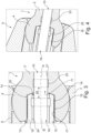
Fig. 1 in einer Schnittansicht entlang der Längsachsen A und B ausschnittsweise ein Implantat nach einer ersten Ausführungsform der Erfindung in Form einer Pedikelschraube mit einem Implantationsinstrument nach einer ersten Ausführungsform der Erfindung in Wirkeingriff, -
Fig. 2 eine Ausführungsform ähnlich derFig. 1 in einer perspektivischen Ansicht, -
Fig. 3 in einer Schnittansicht entlang der Längsachsen A und B ausschnittsweise ein Implantat nach einer zweiten Ausführungsform der Erfindung in Form einer Pedikelschraube mit einem Implantationsinstrument nach einer zweiten Ausführungsform der Erfindung in Wirkeingriff, -
Fig. 4 eine Ausführungsform derFig. 3 in einer perspektivischen Ansicht und -
Fig. 5 die Ausführungsform derFiguren 1 und 2 mit nicht geschnittenen Implantationsinstrument. - Die vorliegende Beschreibung der Erfindung anhand der Figuren erfolgt mit Bezug auf eine Pedikelschraube 1. Die Erfindung betrifft jedoch insbesondere eine Knochenschraube. Die Bezeichnung Pedikelschraube ist daher als auf eine Knochenschraube gerichtet zu verstehen und umgekehrt.
- Die Pedikelschraube 1 besitzt eine Längsachse A und weist einen in deren axialer Richtung verlaufenden Schraubenschaft 2 mit Außengewinde 3 oder Knochengewinde 3 auf. Am proximalen Ende des Schraubenschafts 2 ist ein kugelförmiger Schraubenkopf 4 ausgebildet, der wiederum eine Aufnahmehülse 5, auch als Tulpe 5 bezeichnet, infolge seiner Kugelform schwenkpositionierbar trägt. Die Tulpe 5 ist im Wesentlichen U-förmig ausgebildet mit gegenüberliegenden Wandabschnitten 6, 7, allgemein auch als Hülsenflanken bezeichnet, und einem dazwischen ausgebildeten, in radialer Richtung verlaufenden Spalt 8, der einen Aufnahmeraum für einen in den Figuren nicht dargestellten Längsträger oder Steg bildet. Die Tulpe 5 ist mit einem in axialer Richtung verlaufende Innengewinde 9 versehen, mit dem eine nicht gezeigte Klemmschraube (Setscrew) nach Einlegen des Längsträgers in die Tulpe 5 verschraubt wird, um diesen zu verklemmen und zu fixieren.
- Im Schraubenschaft 2 der Pedikelschraube 1 ist ein Injektionskanal 10 ausgebildet, der in Richtung der Längsachse A ausgerichtet ist und (in den Figuren nicht zu erkennen) im Wesentlichen durch die gesamte Länge des Schraubenschafts 2 läuft. Der Injektionskanal 10 weist am kopfseitigen Ende eine proximale Einlassöffnung 11 und am distalen Ende des Schafts 2 und/oder über den Schraubenschaft 2 verteilt eine oder mehrere Auslassöffnungen auf. Durch den Injektionskanal 10 wird mittels des in den Figuren abschnittweise dargestellten Implantationsinstruments 12 Knochenverbindungsmaterial oder Knochenzement zu den Auslassöffnungen der in einem Knochen platzierten/eingeschraubten Pedikelschraube 1 gefördert, tritt aus diesen aus und zementiert die Pedikelschraube 1 im Knochen ein.
- Der kugelförmige Schraubenkopf 4 weist eine zentrale Werkzeugaufnahme 13 in Form einer Ausnehmung auf. Die Werkzeugaufnahme 13 besitzt, wie insbesondere
Figur 5 deutlich zeigt, eine als Torx-Aufnahme ausgebildete Eingriffkontur 14 für eine entsprechend geformte Werkzeugkontur 15 des Implantationsinstruments 12. Wie in denFiguren 1 und3 gezeigt ist, ist darüber hinaus in der Werkzeugaufnahme 13 eine Verbindungskontur 16, hier in Form eines Innengewindes 16 ausgebildet, die sich mit der Eingriffkontur 14 überlagert. Das Innengewinde 16 dient einem schraubenden Eingriff mit einer Verbindungsstruktur 17 des Implantationsinstruments 12, hier in Form eines passend geformten Außengewindes 17. - Die
Figuren 1 und3 zeigen, dass das Implantationsinstrument 12 eine Injektionskanüle 18 mit einer Längsachse B aufweist. In dieser ist in Richtung der Längsachse B ein Innenkanal 19 ausgebildet, der am distalen Ende der Injektionskanüle 18 eine distale Auslassöffnung 20 aufweist. Das gegenüberliegende, in den Figuren nicht dargestellte Ende des Innenkanals 19 ist fluidisch mit einem Reservoir oder Behälter für Knochenverbindungsmaterial verbunden. Der Innenkanal 19 dient dazu, Knochenverbindungsmaterial von diesem Reservoir zur Auslassöffnung 20, und aus dieser über die proximale Einlassöffnung 11 in den Injektionskanal 10 der Pedikelschraube 1 zu fördern. - Zu diesem Zweck ist das Implantationsinstrument 12 in der nachfolgend beschriebenen Weise mit der Pedikelschraube 1 koppelbar: Über das Innengewinde 16 und das Außengewinde 17 wird das Implantationswerkzeug 12 derart in der Werkzeugaufnahme 13 des Schraubenkopfs 4 platziert und daran gehalten, dass über den Innenkanal 19 und den Injektionskanal 10 eine nach außen für das Knochenverbindungsmaterial dichte Strömungsbahn vom Zementreservoir zu den nicht gezeigten Auslassöffnungen der Pedikelschraube 1 ausgebildet ist. Bei einer derartigen bestimmungsgemäßer Anordnung des Instruments 12 in der Werkzeugaufnahme 13 stehen auch die Eingriffkontur 14 der Pedikelschraube 1 mit der Werkzeugkontur 15 des Implantationsinstruments 12 in Eingriff, derart, dass die Pedikelschraube 1 mit dem Implantationsinstrument 12 in einen Knochen eingeschraubt werden kann. Nach Erreichen der bestimmungsgemäßen Endlage der Pedikelschraube 1 wird über die Injektionskanüle Knochenverbindungsmaterial eingeleitet. Dieses strömt durch den Innenkanal 19 und den Injektionskanal 10 zu den Auslassöffnungen der Pedikelschraube 1 und aus diesen hinaus in zwischen der Pedikelschraube 1 und der Knochensubstanz vorliegende Kavitäten. Nach einer gewissen Zeitspanne ist das Material zumindest teilweise ausgehärtet und verfestigt, so dass das Implantationsinstrument 12 von der Pedikelschraube 1 gelöst und entfernt werden kann.
- Zu diesem Zweck werden einfach das Innengewinde 16 und das Außengewinde 17 auseinander geschraubt, wodurch das Instrument 12 und dessen Injektionskanüle 18 in axialer Richtung vom Schraubenkopf entfernt werden. Dabei kommt die erfindungsgemäße Ausgestaltung der Kanäle 10, 19 mit einem Versatz zum Tragen. Im Injektionskanal 10 ist bei der Ausführungsform der
Figuren 1 und 2 in einem an die proximale Einlassöffnung 11 angrenzenden Bereich in die Wand 21 ein Innengewinde 22 eingebracht, das den Versatz bzw. eine Mehrzahl von Versätzen ausbildet. In den Ausführungsformen derFiguren 3 und 4 ist in die Wand 21 des Injektionskanals 10 ein Hinterschnitt 23 eingebracht. DieFiguren 1 bis 4 zeigen, dass in die Wand 24 des Innenkanals 19 der Injektionskanüle 18 ebenfalls ein Versatz eingebracht ist, hier jeweils in Form eines Hinterschnitts 25. Eine Alternative ist hier ein in den Figuren nicht dargestelltes Innengewinde. - In den Kanälen 10, 19 vorliegendes Knochenverbindungsmaterial, siehe zum Beispiel in
Figur 5 , dringt im Rahmen des Injektionsvorgangs in die Gewindegänge des Innengewindes 22 bzw. die Hinterschnitte 23, 25 ein und härtet dort aus. Man kann also sagen, dass der Versatz der Kanäle 10, 19 in Form des Innengewindes 22 bzw. der Hinterschnitte 23, 25 in dem Knochenverbindungsmaterial abgeformt wird und dieses in dieser Form aushärtet. Es ist durch Formschluss mit dem entsprechenden Versatz nicht in Richtung der jeweiligen Längsachse A bzw. B positionierbar. Bei einem Entfernen des Implantationsinstruments 12 in axialer Richtung fort von der Pedikelschraube 1 kommt es daher zu einem Bruch bzw. Abscheren des innerhalb der Kanäle 10, 19 vorliegenden Knochenverbindungsmaterials in einem zwischen den beiden Hinterschnitten 23 und 25 bzw. zwischen dem Hinterschnitt 25 und dem Innengewinde gelegenen (Sollbruch-)Bereich 26. Dadurch wird sichergestellt, dass ausgehärtetes Knochenverbindungsmaterial möglichst nahe an der proximalen Einlassöffnung 11 des Kanals 10 in der Pedikelschraube 1 bzw. der Auslassöffnung 20 des Kanals 19 in der Injektionskanüle 18 abbricht und nicht übermäßig vorsteht. - In obiger Ausführungsform ist die Injektionskanüle 18 Teil des Implantationswerkzeugs 12. Bei der Injektionskanüle 18 kann es sich auch um ein separates, in die Pedikelschraube 1 einschraubbares Bauteil handeln, welches ebenfalls mit einem Hinterschnitt 25 bzw. radialen Versatz versehen ist.
-
- 1
- Pedikelschraube
- 2
- Schraubenschaft
- 3
- Außengewinde, Knochengewinde
- 4
- Schraubenkopf
- 5
- Aufnahmehülse, Tulpe
- 6
- Wandabschnitt
- 7
- Wandabschnitt
- 8
- Spalt, Aufnahmeraum
- 9
- Innengewinde der Tulpe
- 10
- Injektionskanal
- 11
- proximale Einlassöffnung
- 12
- Implantationsinstrument
- 13
- Werkzeugaufnahme
- 14
- Eingriffkontur
- 15
- Werkzeugkontur, Torx-Kopf
- 16
- Verbindungskontur, Innengewinde
- 17
- Verbindungsstruktur, Außengewinde
- 18
- Injektionskanüle
- 19
- Innenkanal
- 20
- distale Auslassöffnung
- 21
- Wand
- 22
- Innengewinde als Versatz
- 23
- Hinterschnitt als Versatz
- 24
- Wand
- 25
- Hinterschnitt als Versatz
- 26
- Bruchstelle
Claims (16)
- Implantationsinstrument (12) für ein Knochenimplantat (1) vorzugsweise in Form einer Pedikelschraube, aufweisend eine Injektionskanüle (18) mit einem Innenkanal (19) mit einer Längsachse B zum Injizieren von Knochenverbindungsmaterial, wobei der Innenkanal (19) eine distale Auslassöffnung (20) für Knochenverbindungsmaterial aufweist und dort einen vorbestimmten Innenkanaldurchmesser hat, wobei die den Innenkanal (19) umgebende Wand (24) der Injektionskanüle (18) ausgehend von der distalen Auslassöffnung (20) einen zur Längsachse B radialen Versatz (25) aufweist, vorzugsweise ein in die Wand (24) des Innenkanals (19) eingebrachtes Gewinde oder eine in die Wand (24) des Innenkanals (19) eingebrachte Nut, aufweist, der sich gegenüber dem sowohl distal als auch proximal zum Versatz (25) ausgebildeten vorbestimmten Innenkanaldurchmesser radial nach außen erstreckt,
dadurch gekennzeichnet, dass der radiale Versatz (25) zumindest in einem Bereich der Wand (24) ausgebildet ist, der von der distalen Auslassöffnung (20) zwischen ca. 0,5 mm bis ca. 10 mm beabstandet ist. - Implantationsinstrument (12) nach Anspruch 1, dadurch gekennzeichnet, dass der radiale Versatz (25) der Injektionskanüle (18) durch zumindest eine in die Wand (24) des Innenkanals (19) eingebrachte Stufe oder Schulter ausgebildet ist und/oder in umfänglicher Richtung zumindest abschnittsweise umlaufend ausgebildet ist.
- Implantationsinstrument (12) nach einem der vorhergehenden Ansprüche, dadurch gekennzeichnet, dass der radiale Versatz (25) der Injektionskanüle (18) durch einen in die Wand (24) des Innenkanals (19) eingebrachten Hinterschnitt (25) ausgebildet ist.
- Implantationsinstrument (12) nach einem der vorhergehenden Ansprüche, dadurch gekennzeichnet, dass der radiale Versatz (25) der Injektionskanüle (18) in einem Bereich der Wand (24) ausgebildet ist, der von der distalen Auslassöffnung (20) zwischen ca. 1 mm bis ca. 7,5 mm, bevorzugt zwischen ca. 1,5 mm bis ca. 5 mm und noch bevorzugter zwischen ca. 2 mm bis ca. 3 mm beabstandet ist.
- Implantationsinstrument (12) nach einem der vorhergehenden Ansprüche, dadurch gekennzeichnet, dass die Injektionskanüle (18) eine Verbindungsstruktur (17) zum lösbaren Verbinden mit einer Werkzeugaufnahme (13) des Knochenimplantats aufweist, insbesondere in Form eines Gewindes (17) oder einer Bajonettstruktur.
- Implantationsinstrument (12) nach einem der vorhergehenden Ansprüche, dadurch gekennzeichnet, dass die Injektionskanüle (18) als Implantatwerkzeug ausgebildet ist und einen zur Werkzeugaufnahme (13) passende Werkzeugkontur (15) aufweist, insbesondere in Form eines Außensechskants oder eines Torx-Kopfes (15).
- Implantationssystem miteinem Implantationsinstrument (12) für ein Knochenimplantat (1) vorzugsweise in Form einer Pedikelschraube, aufweisend eine Injektionskanüle (18) mit einem Innenkanal (19) mit einer Längsachse B zum Injizieren von Knochenverbindungsmaterial, wobei der Innenkanal (19) eine distale Auslassöffnung (20) für Knochenverbindungsmaterial aufweist und dort einen vorbestimmten Innenkanaldurchmesser hat, wobei die den Innenkanal (19) umgebende Wand (24) der Injektionskanüle (18) ausgehend von der distalen Auslassöffnung (20) einen zur Längsachse B radialen Versatz (25) aufweist, vorzugsweise ein in die Wand (24) des Innenkanals (19) eingebrachtes Gewinde oder eine in die Wand (24) des Innenkanals (19) eingebrachte Nut aufweist, der sich gegenüber dem vorbestimmten Innenkanaldurchmesser, der sich sowohl distal als auch proximal zum Versatz (25) ausbildet, radial nach außen erstreckt, vorzugsweise einem Implantationsinstrument (12) nach einem der vorhergehenden Ansprüche, sowieeinem Knochenimplantat (1) mit einem distalen Implantatschaft (2), der zum Versenken in einem Knochen ausgebildet ist, und einem proximalen Implantatkopf (4) mit einer Werkzeugaufnahme (13) für ein Implantationswerkzeug (12), von der sich ein Injektionskanal (10) zum Injizieren eines Knochenverbindungsmaterials in den Implantatschaft (2) erstreckt und dort einen vorbestimmten Injektionskanaldurchmesser hat, wobei die den Injektionskanal (10) umgebende Wand (21) ausgehend von der Werkzeugaufnahme (13) einen Versatz, vorzugsweise ein in die Wand (21) des Injektionskanals (10) eingebrachtes Gewinde (22) oder eine in die Wand (21) des Injektionskanals (10) eingebrachte Nut (23), aufweist, der sich gegenüber dem vorbestimmten Injektionskanaldurchmesser proximal und distal zum Versatz radial nach außen erstreckt.
- Implantationssystem nach Anspruch 7, dadurch gekennzeichnet, dass der radiale Versatz (22, 23) des Knochenimplantats (1) durch zumindest eine in der Wand (21) des Injektionskanals (10) eingebrachte Stufe oder Schulter ausgebildet ist und/oder in Umfangsrichtung zumindest abschnittsweise umlaufend ausgebildet ist.
- Implantationssystem nach einem der Ansprüche 7 und 8, dadurch gekennzeichnet, dass der radiale Versatz (22, 23) des Knochenimplantats (1) durch einen in die Wand (21) des Injektionskanals (10) eingebrachten Hinterschnitt (23) ausgebildet ist.
- Implantationssystem nach einem der Ansprüche 7 bis 9, dadurch gekennzeichnet, dass der radiale Versatz (22, 23) des Knochenimplantats (1) in einem Bereich der Wand (21) ausgebildet ist, der von der proximalen Einlassöffnung (11) wenigstens ca. 0,5 mm und maximal ca. 10 mm beabstandet ist, vorzugsweise zwischen ca. 1 mm bis ca. 7,5 mm, bevorzugter zwischen ca. 1,5 mm bis ca. 5 mm und noch bevorzugter zwischen ca. 2 mm bis ca. 3 mm beabstandet ist.
- Implantationssystem nach einem der Ansprüche 7 bis 10, dadurch gekennzeichnet, dass die Tiefe des Versatzes (22, 23) des Knochenimplantats (1) ausgehend von dem Injektionskanaldurchmesser in radialer Richtung zwischen ca. 0,1 mm bis 3 mm, vorzugsweise zwischen ca. 0,2 mm bis 2 mm und besonders bevorzugt zwischen ca. 0,3 mm bis ca. 1,5 mm beträgt.
- Implantationssystem nach einem der Ansprüche 7 bis 11, dadurch gekennzeichnet, dass das Knochenimplantat (1) eine Knochenschraube (1) ist, insbesondere eine Pedikelschraube (1), deren Implantatkopf (4) insbesondere als Kugelkopf (4) ausgebildet ist und/oder eine Werkzeugaufnahme (13) für ein Schraubwerkzeug (12) aufweist, wobei die proximale Einlassöffnung (11) in einer distalen Begrenzungsfläche der Werkzeugaufnahme (13) ausgebildet ist.
- Implantationssystem nach einem der Ansprüche 7 bis 12, dadurch gekennzeichnet, dass die Werkzeugaufnahme (13) des Knochenimplantats (1) eine Verbindungsstruktur (16) zum lösbaren Verbinden mit einer Injektionskanüle (18) zum Injizieren von Knochenverbindungsmaterial aufweist, insbesondere in Form eines Gewindes, Innengewindes (16) oder einer Bajonettstruktur und/oder dass die Werkzeugaufnahme (13) eine Eingriffkontur (14) für ein Implantationswerkzeug (12) aufweist, mit dem das Knochenimplantat (1) bei einer Implantation implantiert wird, insbesondere in Form eines Innensechskants oder einer Torx-Aufnahme.
- Knochenimplantat (1) in Form einer Pedikelschraube für ein Implantationssystem nach einem der Ansprüche 7 bis 13 mit einem distalen Implantatschaft (2), der zum Versenken in einem Knochen ausgebildet ist, und einem proximalen Implantatkopf (4) mit einer Werkzeugaufnahme (13) für ein Implantationswerkzeug (12), von der sich ein Injektionskanal (10) zum Injizieren eines Knochenverbindungsmaterials in den Implantatschaft (2) erstreckt und dort einen vorbestimmten Injektionskanaldurchmesser hat,
dadurch gekennzeichnet, dass
die den Injektionskanal (10) umgebende Wand (21) ausgehend von der Werkzeugaufnahme (13) einen Versatz in Form einer in die Wand (21) des Injektionskanals (10) eingebrachten singulären Nut (23) aufweist, die sich gegenüber dem vorbestimmten Injektionskanaldurchmesser, der sich proximal und distal zum Versatz ausbildet, radial nach außen erstreckt, wobei die singuläre Nut (23) durch einen einzigen, in die Wand (21) des Injektionskanals (10) eingebrachten Hinterschnitt ausgebildet ist. - Knochenimplantat (1) nach Anspruch 14, dadurch gekennzeichnet, dass die Nut (23) in einem Bereich der Wand (21) ausgebildet ist, der von der proximalen Einlassöffnung (11) wenigstens ca. 0,5 mm und maximal ca. 10 mm beabstandet ist, vorzugsweise zwischen ca. 1 mm bis ca. 7,5 mm, bevorzugter zwischen ca. 1,5 mm bis ca. 5 mm und noch bevorzugter zwischen ca. 2 mm bis ca. 3 mm in Richtung Distal beabstandet ist.
- Knochenimplantat (1) nach einem der 14 und 15, dadurch gekennzeichnet, dass die Tiefe der Nut (23) in radialer Richtung ausgehend von dem Injektionskanaldurchmesser zwischen ca. 0,1 mm bis 3 mm, vorzugsweise zwischen ca. 0,2 mm bis 2 mm und besonders bevorzugt zwischen ca. 0,3 mm bis ca. 1,5 mm beträgt.
Applications Claiming Priority (2)
| Application Number | Priority Date | Filing Date | Title |
|---|---|---|---|
| DE102016106308.8A DE102016106308A1 (de) | 2016-04-06 | 2016-04-06 | Knochenimplantat mit Versatz im Injektionskanal sowie Implantationswerkzeug hierfür |
| PCT/EP2017/057966 WO2017174569A1 (de) | 2016-04-06 | 2017-04-04 | Knochenimplantat mit versatz im injektionskanal sowie implantationswerkzeug hierfür |
Publications (2)
| Publication Number | Publication Date |
|---|---|
| EP3439566A1 EP3439566A1 (de) | 2019-02-13 |
| EP3439566B1 true EP3439566B1 (de) | 2024-05-08 |
Family
ID=58503582
Family Applications (1)
| Application Number | Title | Priority Date | Filing Date |
|---|---|---|---|
| EP17716162.7A Active EP3439566B1 (de) | 2016-04-06 | 2017-04-04 | Knochenimplantat mit versatz im injektionskanal sowie implantationswerkzeug hierfür |
Country Status (5)
| Country | Link |
|---|---|
| US (1) | US20190151003A1 (de) |
| EP (1) | EP3439566B1 (de) |
| DE (1) | DE102016106308A1 (de) |
| ES (1) | ES2993449T3 (de) |
| WO (1) | WO2017174569A1 (de) |
Families Citing this family (1)
| Publication number | Priority date | Publication date | Assignee | Title |
|---|---|---|---|---|
| US12440255B2 (en) | 2021-11-08 | 2025-10-14 | Medos International Sárl | Bone screw inserters and methods |
Family Cites Families (12)
| Publication number | Priority date | Publication date | Assignee | Title |
|---|---|---|---|---|
| US7338493B1 (en) * | 2002-06-28 | 2008-03-04 | Biomet Manufacturing Corp. | Method and apparatus for cementing a screw anchor |
| US7354442B2 (en) * | 2003-05-05 | 2008-04-08 | Warsaw Orthopedic, Inc. | Bone anchor and methods of using the same |
| US20070055257A1 (en) * | 2005-06-30 | 2007-03-08 | Alex Vaccaro | Cannulated screw access system |
| US20090264895A1 (en) * | 2008-04-22 | 2009-10-22 | Warsaw Orthopedic, Inc. | Systems and methods for implanting a bone fastener and delivering a bone filling material |
| DE102008024440B4 (de) | 2008-05-13 | 2022-06-09 | Aesculap Ag | Implantat und Implantationssystem |
| US20110144703A1 (en) * | 2009-02-24 | 2011-06-16 | Krause William R | Flexible Screw |
| US20130072984A1 (en) * | 2011-09-21 | 2013-03-21 | James C. Robinson | Fenestrated bone screws and methods of bone fastening and stabilization |
| DE202012008715U1 (de) | 2012-09-12 | 2013-04-12 | Orange Spine GmbH | Augmentierbare Pedikelschrauben für die Wirbelsäulenchirurgie |
| US9326801B2 (en) * | 2013-01-08 | 2016-05-03 | Nicholas Poulos | Fenestrated bone screw and method of injecting bone cement into bone structure |
| CN203252718U (zh) | 2013-03-05 | 2013-10-30 | 吴志宏 | 可注射椎弓根螺钉 |
| DE102013109895A1 (de) | 2013-09-10 | 2015-03-12 | Aesculap Ag | Medizinisches Instrument |
| DE102014109200A1 (de) * | 2014-07-01 | 2016-01-07 | Aesculap Ag | Medizinischer Schraubendreher, Schaft für den medizinischen Schraubendreher und Verfahren zum Einbringen von Pedikelschrauben |
-
2016
- 2016-04-06 DE DE102016106308.8A patent/DE102016106308A1/de not_active Withdrawn
-
2017
- 2017-04-04 ES ES17716162T patent/ES2993449T3/es active Active
- 2017-04-04 WO PCT/EP2017/057966 patent/WO2017174569A1/de not_active Ceased
- 2017-04-04 US US16/091,750 patent/US20190151003A1/en not_active Abandoned
- 2017-04-04 EP EP17716162.7A patent/EP3439566B1/de active Active
Also Published As
| Publication number | Publication date |
|---|---|
| DE102016106308A1 (de) | 2017-10-12 |
| WO2017174569A1 (de) | 2017-10-12 |
| ES2993449T3 (en) | 2024-12-30 |
| EP3439566A1 (de) | 2019-02-13 |
| US20190151003A1 (en) | 2019-05-23 |
Similar Documents
| Publication | Publication Date | Title |
|---|---|---|
| EP0409364B1 (de) | Verbindungselement für die Osteosynthese | |
| EP1096892B1 (de) | Knochenschraube, insbesondere für den einsatz bei translaminärer wirbelverschraubung | |
| EP1681024B1 (de) | Knochenverankerungselement | |
| DE69923962T2 (de) | Knochenimplantat mit einer reversiblen befestigungsvorrichtung | |
| DE10246386B4 (de) | Knochenschraube, Knochenfixationseinrichtung und Halteelement | |
| DE69915254T2 (de) | Knochenschraube für orthopädische Chirurgie | |
| DE69937875T2 (de) | Knochenschraube für äussere Fixatoren | |
| DE1055750B (de) | Chirurgische Schraubverbindung zur Verwendung bei Schenkelhalsbruechen | |
| EP1110510A1 (de) | Schraube mit dezentralem Antrieb | |
| WO2001026568A1 (de) | Knochenschraube | |
| EP1440664A2 (de) | Implantat für Osteosynthese | |
| WO2014147104A1 (de) | Wirbelsäulenstabilisierungssystem und chirurgisches befestigungselement für ein wirbelsäulenstabilisierungssystem | |
| DE102008024440B4 (de) | Implantat und Implantationssystem | |
| DE102017101348A1 (de) | Achsgenauer Schraubendreher | |
| DE102008017741A1 (de) | Vorrichtung zur Stabilisierung von Röhrenknochenbrüchen | |
| EP2701622B1 (de) | Verschlusseinrichtung für kanülierte knochenschrauben | |
| EP1539006B1 (de) | Intramedullärer osteosynthese-nagel zum versorgen von röhrenknochenfrakturen | |
| EP1350478B1 (de) | Kanüle zum Applizieren von medizinischen Stoffen | |
| EP3439566A1 (de) | Knochenimplantat mit versatz im injektionskanal sowie implantationswerkzeug hierfür | |
| EP3742993B1 (de) | Intravertebrale schraube | |
| DE10308338B4 (de) | Knochendübel | |
| DE102014107495A1 (de) | Knochenschraubensystem | |
| DE69921797T2 (de) | Femurprothese | |
| DE19504115A1 (de) | Vorrichtung zur Behandlung von Schenkelhalsfrakturen | |
| DE102006032811A1 (de) | Femurkopf-Implantat |
Legal Events
| Date | Code | Title | Description |
|---|---|---|---|
| STAA | Information on the status of an ep patent application or granted ep patent |
Free format text: STATUS: UNKNOWN |
|
| STAA | Information on the status of an ep patent application or granted ep patent |
Free format text: STATUS: THE INTERNATIONAL PUBLICATION HAS BEEN MADE |
|
| PUAI | Public reference made under article 153(3) epc to a published international application that has entered the european phase |
Free format text: ORIGINAL CODE: 0009012 |
|
| STAA | Information on the status of an ep patent application or granted ep patent |
Free format text: STATUS: REQUEST FOR EXAMINATION WAS MADE |
|
| 17P | Request for examination filed |
Effective date: 20180118 |
|
| AK | Designated contracting states |
Kind code of ref document: A1 Designated state(s): AL AT BE BG CH CY CZ DE DK EE ES FI FR GB GR HR HU IE IS IT LI LT LU LV MC MK MT NL NO PL PT RO RS SE SI SK SM TR |
|
| AX | Request for extension of the european patent |
Extension state: BA ME |
|
| DAV | Request for validation of the european patent (deleted) | ||
| DAX | Request for extension of the european patent (deleted) | ||
| STAA | Information on the status of an ep patent application or granted ep patent |
Free format text: STATUS: EXAMINATION IS IN PROGRESS |
|
| 17Q | First examination report despatched |
Effective date: 20230214 |
|
| GRAP | Despatch of communication of intention to grant a patent |
Free format text: ORIGINAL CODE: EPIDOSNIGR1 |
|
| STAA | Information on the status of an ep patent application or granted ep patent |
Free format text: STATUS: GRANT OF PATENT IS INTENDED |
|
| RIC1 | Information provided on ipc code assigned before grant |
Ipc: A61B 17/84 20060101ALI20231110BHEP Ipc: A61B 17/88 20060101AFI20231110BHEP |
|
| INTG | Intention to grant announced |
Effective date: 20231204 |
|
| GRAS | Grant fee paid |
Free format text: ORIGINAL CODE: EPIDOSNIGR3 |
|
| GRAA | (expected) grant |
Free format text: ORIGINAL CODE: 0009210 |
|
| STAA | Information on the status of an ep patent application or granted ep patent |
Free format text: STATUS: THE PATENT HAS BEEN GRANTED |
|
| AK | Designated contracting states |
Kind code of ref document: B1 Designated state(s): AL AT BE BG CH CY CZ DE DK EE ES FI FR GB GR HR HU IE IS IT LI LT LU LV MC MK MT NL NO PL PT RO RS SE SI SK SM TR |
|
| REG | Reference to a national code |
Ref country code: GB Ref legal event code: FG4D Free format text: NOT ENGLISH |
|
| REG | Reference to a national code |
Ref country code: CH Ref legal event code: EP |
|
| REG | Reference to a national code |
Ref country code: DE Ref legal event code: R096 Ref document number: 502017016100 Country of ref document: DE |
|
| REG | Reference to a national code |
Ref country code: IE Ref legal event code: FG4D Free format text: LANGUAGE OF EP DOCUMENT: GERMAN |
|
| REG | Reference to a national code |
Ref country code: LT Ref legal event code: MG9D |
|
| REG | Reference to a national code |
Ref country code: NL Ref legal event code: MP Effective date: 20240508 |
|
| PG25 | Lapsed in a contracting state [announced via postgrant information from national office to epo] |
Ref country code: IS Free format text: LAPSE BECAUSE OF FAILURE TO SUBMIT A TRANSLATION OF THE DESCRIPTION OR TO PAY THE FEE WITHIN THE PRESCRIBED TIME-LIMIT Effective date: 20240908 |
|
| PG25 | Lapsed in a contracting state [announced via postgrant information from national office to epo] |
Ref country code: BG Free format text: LAPSE BECAUSE OF FAILURE TO SUBMIT A TRANSLATION OF THE DESCRIPTION OR TO PAY THE FEE WITHIN THE PRESCRIBED TIME-LIMIT Effective date: 20240508 |
|
| PG25 | Lapsed in a contracting state [announced via postgrant information from national office to epo] |
Ref country code: HR Free format text: LAPSE BECAUSE OF FAILURE TO SUBMIT A TRANSLATION OF THE DESCRIPTION OR TO PAY THE FEE WITHIN THE PRESCRIBED TIME-LIMIT Effective date: 20240508 Ref country code: FI Free format text: LAPSE BECAUSE OF FAILURE TO SUBMIT A TRANSLATION OF THE DESCRIPTION OR TO PAY THE FEE WITHIN THE PRESCRIBED TIME-LIMIT Effective date: 20240508 |
|
| PG25 | Lapsed in a contracting state [announced via postgrant information from national office to epo] |
Ref country code: GR Free format text: LAPSE BECAUSE OF FAILURE TO SUBMIT A TRANSLATION OF THE DESCRIPTION OR TO PAY THE FEE WITHIN THE PRESCRIBED TIME-LIMIT Effective date: 20240809 |
|
| PG25 | Lapsed in a contracting state [announced via postgrant information from national office to epo] |
Ref country code: PT Free format text: LAPSE BECAUSE OF FAILURE TO SUBMIT A TRANSLATION OF THE DESCRIPTION OR TO PAY THE FEE WITHIN THE PRESCRIBED TIME-LIMIT Effective date: 20240909 |
|
| PG25 | Lapsed in a contracting state [announced via postgrant information from national office to epo] |
Ref country code: NL Free format text: LAPSE BECAUSE OF FAILURE TO SUBMIT A TRANSLATION OF THE DESCRIPTION OR TO PAY THE FEE WITHIN THE PRESCRIBED TIME-LIMIT Effective date: 20240508 |
|
| PG25 | Lapsed in a contracting state [announced via postgrant information from national office to epo] |
Ref country code: PL Free format text: LAPSE BECAUSE OF FAILURE TO SUBMIT A TRANSLATION OF THE DESCRIPTION OR TO PAY THE FEE WITHIN THE PRESCRIBED TIME-LIMIT Effective date: 20240508 |
|
| PG25 | Lapsed in a contracting state [announced via postgrant information from national office to epo] |
Ref country code: LV Free format text: LAPSE BECAUSE OF FAILURE TO SUBMIT A TRANSLATION OF THE DESCRIPTION OR TO PAY THE FEE WITHIN THE PRESCRIBED TIME-LIMIT Effective date: 20240508 |
|
| PG25 | Lapsed in a contracting state [announced via postgrant information from national office to epo] |
Ref country code: LV Free format text: LAPSE BECAUSE OF FAILURE TO SUBMIT A TRANSLATION OF THE DESCRIPTION OR TO PAY THE FEE WITHIN THE PRESCRIBED TIME-LIMIT Effective date: 20240508 Ref country code: IS Free format text: LAPSE BECAUSE OF FAILURE TO SUBMIT A TRANSLATION OF THE DESCRIPTION OR TO PAY THE FEE WITHIN THE PRESCRIBED TIME-LIMIT Effective date: 20240908 Ref country code: HR Free format text: LAPSE BECAUSE OF FAILURE TO SUBMIT A TRANSLATION OF THE DESCRIPTION OR TO PAY THE FEE WITHIN THE PRESCRIBED TIME-LIMIT Effective date: 20240508 Ref country code: GR Free format text: LAPSE BECAUSE OF FAILURE TO SUBMIT A TRANSLATION OF THE DESCRIPTION OR TO PAY THE FEE WITHIN THE PRESCRIBED TIME-LIMIT Effective date: 20240809 Ref country code: FI Free format text: LAPSE BECAUSE OF FAILURE TO SUBMIT A TRANSLATION OF THE DESCRIPTION OR TO PAY THE FEE WITHIN THE PRESCRIBED TIME-LIMIT Effective date: 20240508 Ref country code: BG Free format text: LAPSE BECAUSE OF FAILURE TO SUBMIT A TRANSLATION OF THE DESCRIPTION OR TO PAY THE FEE WITHIN THE PRESCRIBED TIME-LIMIT Effective date: 20240508 Ref country code: PT Free format text: LAPSE BECAUSE OF FAILURE TO SUBMIT A TRANSLATION OF THE DESCRIPTION OR TO PAY THE FEE WITHIN THE PRESCRIBED TIME-LIMIT Effective date: 20240909 Ref country code: PL Free format text: LAPSE BECAUSE OF FAILURE TO SUBMIT A TRANSLATION OF THE DESCRIPTION OR TO PAY THE FEE WITHIN THE PRESCRIBED TIME-LIMIT Effective date: 20240508 Ref country code: NO Free format text: LAPSE BECAUSE OF FAILURE TO SUBMIT A TRANSLATION OF THE DESCRIPTION OR TO PAY THE FEE WITHIN THE PRESCRIBED TIME-LIMIT Effective date: 20240808 Ref country code: NL Free format text: LAPSE BECAUSE OF FAILURE TO SUBMIT A TRANSLATION OF THE DESCRIPTION OR TO PAY THE FEE WITHIN THE PRESCRIBED TIME-LIMIT Effective date: 20240508 Ref country code: RS Free format text: LAPSE BECAUSE OF FAILURE TO SUBMIT A TRANSLATION OF THE DESCRIPTION OR TO PAY THE FEE WITHIN THE PRESCRIBED TIME-LIMIT Effective date: 20240808 |
|
| REG | Reference to a national code |
Ref country code: ES Ref legal event code: FG2A Ref document number: 2993449 Country of ref document: ES Kind code of ref document: T3 Effective date: 20241230 |
|
| PG25 | Lapsed in a contracting state [announced via postgrant information from national office to epo] |
Ref country code: DK Free format text: LAPSE BECAUSE OF FAILURE TO SUBMIT A TRANSLATION OF THE DESCRIPTION OR TO PAY THE FEE WITHIN THE PRESCRIBED TIME-LIMIT Effective date: 20240508 |
|
| PG25 | Lapsed in a contracting state [announced via postgrant information from national office to epo] |
Ref country code: EE Free format text: LAPSE BECAUSE OF FAILURE TO SUBMIT A TRANSLATION OF THE DESCRIPTION OR TO PAY THE FEE WITHIN THE PRESCRIBED TIME-LIMIT Effective date: 20240508 |
|
| PG25 | Lapsed in a contracting state [announced via postgrant information from national office to epo] |
Ref country code: CZ Free format text: LAPSE BECAUSE OF FAILURE TO SUBMIT A TRANSLATION OF THE DESCRIPTION OR TO PAY THE FEE WITHIN THE PRESCRIBED TIME-LIMIT Effective date: 20240508 |
|
| PG25 | Lapsed in a contracting state [announced via postgrant information from national office to epo] |
Ref country code: SK Free format text: LAPSE BECAUSE OF FAILURE TO SUBMIT A TRANSLATION OF THE DESCRIPTION OR TO PAY THE FEE WITHIN THE PRESCRIBED TIME-LIMIT Effective date: 20240508 Ref country code: RO Free format text: LAPSE BECAUSE OF FAILURE TO SUBMIT A TRANSLATION OF THE DESCRIPTION OR TO PAY THE FEE WITHIN THE PRESCRIBED TIME-LIMIT Effective date: 20240508 |
|
| PG25 | Lapsed in a contracting state [announced via postgrant information from national office to epo] |
Ref country code: SM Free format text: LAPSE BECAUSE OF FAILURE TO SUBMIT A TRANSLATION OF THE DESCRIPTION OR TO PAY THE FEE WITHIN THE PRESCRIBED TIME-LIMIT Effective date: 20240508 |
|
| PG25 | Lapsed in a contracting state [announced via postgrant information from national office to epo] |
Ref country code: SM Free format text: LAPSE BECAUSE OF FAILURE TO SUBMIT A TRANSLATION OF THE DESCRIPTION OR TO PAY THE FEE WITHIN THE PRESCRIBED TIME-LIMIT Effective date: 20240508 Ref country code: SK Free format text: LAPSE BECAUSE OF FAILURE TO SUBMIT A TRANSLATION OF THE DESCRIPTION OR TO PAY THE FEE WITHIN THE PRESCRIBED TIME-LIMIT Effective date: 20240508 Ref country code: RO Free format text: LAPSE BECAUSE OF FAILURE TO SUBMIT A TRANSLATION OF THE DESCRIPTION OR TO PAY THE FEE WITHIN THE PRESCRIBED TIME-LIMIT Effective date: 20240508 Ref country code: EE Free format text: LAPSE BECAUSE OF FAILURE TO SUBMIT A TRANSLATION OF THE DESCRIPTION OR TO PAY THE FEE WITHIN THE PRESCRIBED TIME-LIMIT Effective date: 20240508 Ref country code: DK Free format text: LAPSE BECAUSE OF FAILURE TO SUBMIT A TRANSLATION OF THE DESCRIPTION OR TO PAY THE FEE WITHIN THE PRESCRIBED TIME-LIMIT Effective date: 20240508 Ref country code: CZ Free format text: LAPSE BECAUSE OF FAILURE TO SUBMIT A TRANSLATION OF THE DESCRIPTION OR TO PAY THE FEE WITHIN THE PRESCRIBED TIME-LIMIT Effective date: 20240508 |
|
| REG | Reference to a national code |
Ref country code: DE Ref legal event code: R097 Ref document number: 502017016100 Country of ref document: DE |
|
| PLBE | No opposition filed within time limit |
Free format text: ORIGINAL CODE: 0009261 |
|
| STAA | Information on the status of an ep patent application or granted ep patent |
Free format text: STATUS: NO OPPOSITION FILED WITHIN TIME LIMIT |
|
| 26N | No opposition filed |
Effective date: 20250211 |
|
| PG25 | Lapsed in a contracting state [announced via postgrant information from national office to epo] |
Ref country code: SI Free format text: LAPSE BECAUSE OF FAILURE TO SUBMIT A TRANSLATION OF THE DESCRIPTION OR TO PAY THE FEE WITHIN THE PRESCRIBED TIME-LIMIT Effective date: 20240508 |
|
| PGFP | Annual fee paid to national office [announced via postgrant information from national office to epo] |
Ref country code: DE Payment date: 20250417 Year of fee payment: 9 |
|
| PGFP | Annual fee paid to national office [announced via postgrant information from national office to epo] |
Ref country code: ES Payment date: 20250519 Year of fee payment: 9 |
|
| PGFP | Annual fee paid to national office [announced via postgrant information from national office to epo] |
Ref country code: IT Payment date: 20250430 Year of fee payment: 9 |
|
| PGFP | Annual fee paid to national office [announced via postgrant information from national office to epo] |
Ref country code: FR Payment date: 20250422 Year of fee payment: 9 |
|
| PGFP | Annual fee paid to national office [announced via postgrant information from national office to epo] |
Ref country code: CH Payment date: 20250501 Year of fee payment: 9 |
|
| PG25 | Lapsed in a contracting state [announced via postgrant information from national office to epo] |
Ref country code: SE Free format text: LAPSE BECAUSE OF FAILURE TO SUBMIT A TRANSLATION OF THE DESCRIPTION OR TO PAY THE FEE WITHIN THE PRESCRIBED TIME-LIMIT Effective date: 20240508 |
|
| PG25 | Lapsed in a contracting state [announced via postgrant information from national office to epo] |
Ref country code: LU Free format text: LAPSE BECAUSE OF NON-PAYMENT OF DUE FEES Effective date: 20250404 |
|
| PG25 | Lapsed in a contracting state [announced via postgrant information from national office to epo] |
Ref country code: MC Free format text: LAPSE BECAUSE OF FAILURE TO SUBMIT A TRANSLATION OF THE DESCRIPTION OR TO PAY THE FEE WITHIN THE PRESCRIBED TIME-LIMIT Effective date: 20240508 |
|
| REG | Reference to a national code |
Ref country code: BE Ref legal event code: MM Effective date: 20250430 |
|
| PG25 | Lapsed in a contracting state [announced via postgrant information from national office to epo] |
Ref country code: BE Free format text: LAPSE BECAUSE OF NON-PAYMENT OF DUE FEES Effective date: 20250430 |
|
| PGFP | Annual fee paid to national office [announced via postgrant information from national office to epo] |
Ref country code: GB Payment date: 20260324 Year of fee payment: 10 |
|
| PG25 | Lapsed in a contracting state [announced via postgrant information from national office to epo] |
Ref country code: IE Free format text: LAPSE BECAUSE OF NON-PAYMENT OF DUE FEES Effective date: 20250404 |
|
| REG | Reference to a national code |
Ref country code: CH Ref legal event code: U11 Free format text: ST27 STATUS EVENT CODE: U-0-0-U10-U11 (AS PROVIDED BY THE NATIONAL OFFICE) Effective date: 20260501 |