EP3439315A1 - Management system, management method, apparatus, and management device - Google Patents
Management system, management method, apparatus, and management device Download PDFInfo
- Publication number
- EP3439315A1 EP3439315A1 EP17775001.5A EP17775001A EP3439315A1 EP 3439315 A1 EP3439315 A1 EP 3439315A1 EP 17775001 A EP17775001 A EP 17775001A EP 3439315 A1 EP3439315 A1 EP 3439315A1
- Authority
- EP
- European Patent Office
- Prior art keywords
- command
- property
- equipment
- variable
- specific value
- Prior art date
- Legal status (The legal status is an assumption and is not a legal conclusion. Google has not performed a legal analysis and makes no representation as to the accuracy of the status listed.)
- Pending
Links
- 238000007726 management method Methods 0.000 title claims description 68
- 230000004044 response Effects 0.000 claims abstract description 77
- 230000008859 change Effects 0.000 claims abstract description 15
- 238000007599 discharging Methods 0.000 claims description 45
- 230000003750 conditioning effect Effects 0.000 claims description 5
- 238000004891 communication Methods 0.000 description 53
- 238000006243 chemical reaction Methods 0.000 description 20
- 238000010586 diagram Methods 0.000 description 12
- 230000004048 modification Effects 0.000 description 10
- 238000012986 modification Methods 0.000 description 10
- 239000000725 suspension Substances 0.000 description 8
- 238000000034 method Methods 0.000 description 7
- 230000008569 process Effects 0.000 description 6
- 229920003258 poly(methylsilmethylene) Polymers 0.000 description 3
- 238000002296 dynamic light scattering Methods 0.000 description 2
- 239000000446 fuel Substances 0.000 description 2
- 230000006870 function Effects 0.000 description 2
- 238000013061 process characterization study Methods 0.000 description 2
- 230000005540 biological transmission Effects 0.000 description 1
- 230000000694 effects Effects 0.000 description 1
- 238000012423 maintenance Methods 0.000 description 1
- 238000010295 mobile communication Methods 0.000 description 1
- 238000010248 power generation Methods 0.000 description 1
- 230000009467 reduction Effects 0.000 description 1
- 230000007704 transition Effects 0.000 description 1
Images


Classifications
-
- H—ELECTRICITY
- H02—GENERATION; CONVERSION OR DISTRIBUTION OF ELECTRIC POWER
- H02J—CIRCUIT ARRANGEMENTS OR SYSTEMS FOR SUPPLYING OR DISTRIBUTING ELECTRIC POWER; SYSTEMS FOR STORING ELECTRIC ENERGY
- H02J7/00—Circuit arrangements for charging or depolarising batteries or for supplying loads from batteries
- H02J7/34—Parallel operation in networks using both storage and other dc sources, e.g. providing buffering
- H02J7/35—Parallel operation in networks using both storage and other dc sources, e.g. providing buffering with light sensitive cells
-
- H—ELECTRICITY
- H02—GENERATION; CONVERSION OR DISTRIBUTION OF ELECTRIC POWER
- H02J—CIRCUIT ARRANGEMENTS OR SYSTEMS FOR SUPPLYING OR DISTRIBUTING ELECTRIC POWER; SYSTEMS FOR STORING ELECTRIC ENERGY
- H02J13/00—Circuit arrangements for providing remote indication of network conditions, e.g. an instantaneous record of the open or closed condition of each circuitbreaker in the network; Circuit arrangements for providing remote control of switching means in a power distribution network, e.g. switching in and out of current consumers by using a pulse code signal carried by the network
- H02J13/00004—Circuit arrangements for providing remote indication of network conditions, e.g. an instantaneous record of the open or closed condition of each circuitbreaker in the network; Circuit arrangements for providing remote control of switching means in a power distribution network, e.g. switching in and out of current consumers by using a pulse code signal carried by the network characterised by the power network being locally controlled
-
- H—ELECTRICITY
- H02—GENERATION; CONVERSION OR DISTRIBUTION OF ELECTRIC POWER
- H02J—CIRCUIT ARRANGEMENTS OR SYSTEMS FOR SUPPLYING OR DISTRIBUTING ELECTRIC POWER; SYSTEMS FOR STORING ELECTRIC ENERGY
- H02J13/00—Circuit arrangements for providing remote indication of network conditions, e.g. an instantaneous record of the open or closed condition of each circuitbreaker in the network; Circuit arrangements for providing remote control of switching means in a power distribution network, e.g. switching in and out of current consumers by using a pulse code signal carried by the network
- H02J13/00006—Circuit arrangements for providing remote indication of network conditions, e.g. an instantaneous record of the open or closed condition of each circuitbreaker in the network; Circuit arrangements for providing remote control of switching means in a power distribution network, e.g. switching in and out of current consumers by using a pulse code signal carried by the network characterised by information or instructions transport means between the monitoring, controlling or managing units and monitored, controlled or operated power network element or electrical equipment
- H02J13/00022—Circuit arrangements for providing remote indication of network conditions, e.g. an instantaneous record of the open or closed condition of each circuitbreaker in the network; Circuit arrangements for providing remote control of switching means in a power distribution network, e.g. switching in and out of current consumers by using a pulse code signal carried by the network characterised by information or instructions transport means between the monitoring, controlling or managing units and monitored, controlled or operated power network element or electrical equipment using wireless data transmission
-
- H—ELECTRICITY
- H02—GENERATION; CONVERSION OR DISTRIBUTION OF ELECTRIC POWER
- H02J—CIRCUIT ARRANGEMENTS OR SYSTEMS FOR SUPPLYING OR DISTRIBUTING ELECTRIC POWER; SYSTEMS FOR STORING ELECTRIC ENERGY
- H02J13/00—Circuit arrangements for providing remote indication of network conditions, e.g. an instantaneous record of the open or closed condition of each circuitbreaker in the network; Circuit arrangements for providing remote control of switching means in a power distribution network, e.g. switching in and out of current consumers by using a pulse code signal carried by the network
- H02J13/00032—Systems characterised by the controlled or operated power network elements or equipment, the power network elements or equipment not otherwise provided for
- H02J13/00034—Systems characterised by the controlled or operated power network elements or equipment, the power network elements or equipment not otherwise provided for the elements or equipment being or involving an electric power substation
-
- H—ELECTRICITY
- H02—GENERATION; CONVERSION OR DISTRIBUTION OF ELECTRIC POWER
- H02J—CIRCUIT ARRANGEMENTS OR SYSTEMS FOR SUPPLYING OR DISTRIBUTING ELECTRIC POWER; SYSTEMS FOR STORING ELECTRIC ENERGY
- H02J3/00—Circuit arrangements for ac mains or ac distribution networks
- H02J3/12—Circuit arrangements for ac mains or ac distribution networks for adjusting voltage in ac networks by changing a characteristic of the network load
- H02J3/14—Circuit arrangements for ac mains or ac distribution networks for adjusting voltage in ac networks by changing a characteristic of the network load by switching loads on to, or off from, network, e.g. progressively balanced loading
-
- H—ELECTRICITY
- H04—ELECTRIC COMMUNICATION TECHNIQUE
- H04M—TELEPHONIC COMMUNICATION
- H04M11/00—Telephonic communication systems specially adapted for combination with other electrical systems
-
- H—ELECTRICITY
- H04—ELECTRIC COMMUNICATION TECHNIQUE
- H04Q—SELECTING
- H04Q9/00—Arrangements in telecontrol or telemetry systems for selectively calling a substation from a main station, in which substation desired apparatus is selected for applying a control signal thereto or for obtaining measured values therefrom
-
- H—ELECTRICITY
- H02—GENERATION; CONVERSION OR DISTRIBUTION OF ELECTRIC POWER
- H02J—CIRCUIT ARRANGEMENTS OR SYSTEMS FOR SUPPLYING OR DISTRIBUTING ELECTRIC POWER; SYSTEMS FOR STORING ELECTRIC ENERGY
- H02J2310/00—The network for supplying or distributing electric power characterised by its spatial reach or by the load
- H02J2310/10—The network having a local or delimited stationary reach
- H02J2310/12—The local stationary network supplying a household or a building
-
- H—ELECTRICITY
- H02—GENERATION; CONVERSION OR DISTRIBUTION OF ELECTRIC POWER
- H02J—CIRCUIT ARRANGEMENTS OR SYSTEMS FOR SUPPLYING OR DISTRIBUTING ELECTRIC POWER; SYSTEMS FOR STORING ELECTRIC ENERGY
- H02J3/00—Circuit arrangements for ac mains or ac distribution networks
- H02J3/28—Arrangements for balancing of the load in a network by storage of energy
- H02J3/32—Arrangements for balancing of the load in a network by storage of energy using batteries with converting means
-
- Y—GENERAL TAGGING OF NEW TECHNOLOGICAL DEVELOPMENTS; GENERAL TAGGING OF CROSS-SECTIONAL TECHNOLOGIES SPANNING OVER SEVERAL SECTIONS OF THE IPC; TECHNICAL SUBJECTS COVERED BY FORMER USPC CROSS-REFERENCE ART COLLECTIONS [XRACs] AND DIGESTS
- Y02—TECHNOLOGIES OR APPLICATIONS FOR MITIGATION OR ADAPTATION AGAINST CLIMATE CHANGE
- Y02B—CLIMATE CHANGE MITIGATION TECHNOLOGIES RELATED TO BUILDINGS, e.g. HOUSING, HOUSE APPLIANCES OR RELATED END-USER APPLICATIONS
- Y02B90/00—Enabling technologies or technologies with a potential or indirect contribution to GHG emissions mitigation
- Y02B90/20—Smart grids as enabling technology in buildings sector
-
- Y—GENERAL TAGGING OF NEW TECHNOLOGICAL DEVELOPMENTS; GENERAL TAGGING OF CROSS-SECTIONAL TECHNOLOGIES SPANNING OVER SEVERAL SECTIONS OF THE IPC; TECHNICAL SUBJECTS COVERED BY FORMER USPC CROSS-REFERENCE ART COLLECTIONS [XRACs] AND DIGESTS
- Y04—INFORMATION OR COMMUNICATION TECHNOLOGIES HAVING AN IMPACT ON OTHER TECHNOLOGY AREAS
- Y04S—SYSTEMS INTEGRATING TECHNOLOGIES RELATED TO POWER NETWORK OPERATION, COMMUNICATION OR INFORMATION TECHNOLOGIES FOR IMPROVING THE ELECTRICAL POWER GENERATION, TRANSMISSION, DISTRIBUTION, MANAGEMENT OR USAGE, i.e. SMART GRIDS
- Y04S40/00—Systems for electrical power generation, transmission, distribution or end-user application management characterised by the use of communication or information technologies, or communication or information technology specific aspects supporting them
- Y04S40/12—Systems for electrical power generation, transmission, distribution or end-user application management characterised by the use of communication or information technologies, or communication or information technology specific aspects supporting them characterised by data transport means between the monitoring, controlling or managing units and monitored, controlled or operated electrical equipment
- Y04S40/126—Systems for electrical power generation, transmission, distribution or end-user application management characterised by the use of communication or information technologies, or communication or information technology specific aspects supporting them characterised by data transport means between the monitoring, controlling or managing units and monitored, controlled or operated electrical equipment using wireless data transmission
Definitions
- a management system that includes an equipment and a management device that manages the equipment (for example, Patent Literature 1).
- the equipment is an electrical appliance such as an air conditioner and a lighting device, and a distributed power source such as a solar cell, a storage battery, and a fuel power generation device.
- the management device is called, for example, Home Energy Management System (HEMS), Store Energy Management System (SEMS), Building Energy Management System (BEMS), Factory Energy Management System (FEMS), and Cluster/Community Energy Management System (CEMS).
- HEMS Home Energy Management System
- SEMS Store Energy Management System
- BEMS Building Energy Management System
- FEMS Factory Energy Management System
- CEMS Cluster/Community Energy Management System
- the communication standardization between the equipment and the management device is effective, and an attempt to standardize the communication is being made.
- Patent Literature 1 JP 2010-128810 A
- a management system includes an equipment and a management device.
- the management device includes a transmitter configured to transmit a first command to the equipment to instruct an operation of the equipment.
- the equipment includes a controller configured to control an operation of the equipment according to the first command, and a transmitter configured to transmit a response command containing a property indicating a state of the equipment to the management device.
- a property of the first command includes a variable property indicating a variable that can be changed by an operation of the equipment.
- the controller keeps a variable indicated by the variable property without any change when the operation instructed by the first command is kept continuous.
- the transmitter provided in the equipment transmits the response command containing a specific value as the variable property to specify whether the operation is performed according to the first command.
- An equipment is managed by a management device.
- the equipment includes a controller configured to control an operation of the equipment according to a first command that is received from the management device, and a transmitter configured to transmit a response command containing a property indicating a state of the equipment to the management device.
- a property of the first command includes a variable property indicating a variable that can be changed by an operation of the equipment.
- the controller keeps a variable indicated by the variable property without any change when the operation instructed by the first command is kept continuous.
- the transmitter provided in the equipment transmits the response command containing a specific value as the variable property to specify whether the operation is performed according to the first command.
- a management device manages an equipment.
- the management device includes a transmitter configured to transmit a first command to the equipment to instruct an operation of the equipment, and a receiver configured to receive a response command containing a property indicating a state of the equipment from the equipment.
- a property of the first command includes a variable property indicating a variable that can be changed by an operation of the equipment. The variable indicated by the variable property is kept without any change when the operation instructed by the first command is kept continuous.
- the receiver receives the response command containing a specific value as the variable property to specify whether the operation is performed according to the first command.
- a management system 1 includes a facility 100 and an external server 400.
- the facility 100 includes a router 200.
- the router 200 is connected to the external server 400 through a network 300.
- the router 200 forms a local area network, and is connected to the respective devices (for example, a communication device 132 of a PCS 130, a load 150, an EMS 160, a display device 170, etc.).
- the solid line represents a power line
- the dotted line represents a signal line.
- the invention is not limited to the above configuration, and the power line may transmit a signal.
- the facility 100 includes a solar cell 110, a storage battery 120, the PCS 130, a distribution board 140, the load 150, the EMS 160, and the display device 170.
- the storage battery 120 is a device that accumulates power.
- the storage battery 120 outputs the accumulated DC power.
- the storage battery 120 is an example of the distributed power source of which the output can be controlled on the basis of the output control designated from the provider.
- the PCS 130 is an example of a power conditioning system (PCS) that converts the output power from the distributed power source.
- the PCS 130 includes a conversion device 131 and the communication device 132.
- the conversion device 131 converts the DC power from the solar cell 110 into an AC power, and converts the DC power from the storage battery 120 into an AC power. Further, the conversion device 131 converts an AC power from a power grid 10 into a DC power.
- the conversion device 131 is connected to a trunk power line 10L (herein, a trunk power line 10LA and a trunk power line 10LB) connected to the power grid 10 through a first distribution board 140A, and connected to both of the solar cell 110 and the storage battery 120.
- the trunk power line 10LA is a power line that connects the power grid 10 and the first distribution board 140A.
- the trunk power line 10LB is a power line that connects the first distribution board 140A and a second distribution board 140B.
- the conversion device 131 will be described about a hybrid power conditioning system that is connected to the solar cell 110 and the storage battery 120, but the power condition system may be connected to each of the solar cell 110 and the storage battery 120.
- the communication device 132 is connected to the conversion device 131, receives various types of messages to the conversion device 131, and transmits various types of messages from the conversion device 131.
- a protocol for example, unique protocol
- the communication device 132 is connected to the router 200 in a wired or wireless manner.
- the communication device 132 is connected to the external server 400 through the router 200, and receives an output control message designating the output control of the distributed power source from the external server 400.
- the communication device 132 is connected to the EMS 160 through the router 200, and communicates with the EMS 160 as for a predetermined command of a predetermined format.
- the predetermined format is not particularly limited, and an ECHONET Lite system, a SEP2.0 system, or a KNX system may be used for example.
- the predetermined command may be roughly classified into a request command, a request response command that is a response to the request command, or an information notification command.
- the request command is, for example, a SET command or a GET command.
- the request response command is, for example, a SET response command that is a response to the SET command, and a GET response command that is a response to the GET command.
- the information notification command is, for example, an INF command.
- the SET command is a command having a property that instructs a setting or an operation to the PCS 130.
- the SET response command is a command indicating that the SET command is received.
- the GET command is a command containing a property indicating a state of the PCS 130, and acquires the state of the PCS 130.
- the GET response command is a command that contains a property indicating the state of the PCS 130, and contains information requested by the GET command.
- the INF command is a command that contains a property indicating the state of the PCS 130, and notifies the state of the PCS 130.
- the distribution board 140 is connected to the trunk power line 10L.
- the distribution board 140 includes the first distribution board 140A and the second distribution board 140B.
- the first distribution board 140A is connected to the power grid 10 through the trunk power line 10LA, and connected to the solar cell 110 and the storage battery 120 through the conversion device 131.
- the first distribution board 140A controls the power output from the conversion device 131 and the power supplied from the power grid 10 to make the power flow to the trunk power line 10LB.
- the power flowing from the trunk power line 10LB is distributed to the respective equipment (herein, the load 150 and the EMS 160) by the second distribution board 140B.
- the load 150 is an device that consumes the power supplied through the power line.
- the load 150 includes a device such as an air conditioner, a lighting device, a refrigerator, and a television.
- the load 150 may be a single device, or may be a plurality of devices.
- the EMS 160 may control a power generating amount of the solar cell 110, a charging amount of the storage battery 120, and a discharging amount of the storage battery 120.
- the EMS 160 may be configured to be integrally to the distribution board 140.
- the EMS 160 is a device that is connected to the network 300. The function of the EMS 160 may be provided by a cloud service through the network 300.
- the EMS 160 is connected to the respective equipment (for example, the communication device 132 of the PCS 130 and the load 150) through the router 200, and communicates with the respective equipment as for a predetermined command of a predetermined format.
- the EMS 160 is connected to the display device 170 through the router 200, and communicates with the display device 170.
- the EMS 160 may communicate with the display device 170 as for a predetermined command of a predetermined format.
- the predetermined format is a format in conformity to the ECHONET Lite system for example.
- the display device 170 displays the power information indicating the power in the facility 100.
- the display device 170 is, for example, a smart phone, a tablet, a digital television, or a dedicated terminal.
- the display device 170 is connected to the EMS 160 in a wired or wireless manner, and communicates with the EMS 160.
- the display device 170 may communicate with the EMS 160 as for a predetermined command of a predetermined format.
- the display device 170 receives data necessary for the displaying of the power information from the EMS 160.
- the network 300 is a network that connects the EMS 160 and the external server 400.
- the network 300 may be the Internet.
- the network 300 may include a mobile communication network.
- the network 300 may be a dedicated communication line, or may be a general communication line. For example, when the output of the solar cell 110 is equal to or more than a predetermined output, a dedicated communication line is used as the network 300 so as to perform the output control more reliably.
- the external server 400 is a server that is managed by the provider such as an electric power provider, a power transmission/distribution provider, or a retailer.
- the provider designates the output control of the distributed power source.
- the external server 400 transmits the output control message to instruct the output control of the distributed power source.
- the external server 400 may transmit a command (DR; Demand Response) that is an instruction to suppress an amount of current from the power grid 10 to the facility 100.
- DR Demand Response
- the output control message includes a target output control level that indicates a level of the output control of the distributed power source (herein, the solar cell 110).
- the target output control level is determined according to the output (hereinafter, referred to as an equipment recognition output) that is recognized as the output capability (for example, rated output) of the PCS that controls the distributed power source.
- the target output control level may be displayed by an absolute value (for example, ⁇ kW) that is determined according to the equipment recognition output, may be displayed by a relative value (for example, reduction by ⁇ kW) with respect to the equipment recognition output, or may be displayed by a controlled rate (for example, ⁇ %) with respect to the equipment recognition output. Further, while the description has been made by the equipment recognition output, an equipment recognition capacity [kWh] may be employed.
- the equipment recognition output is set to a small one in these output capabilities.
- the equipment recognition output is a sum of the output capabilities of the plurality of PCSs.
- the output control message includes calendar information that indicates a schedule of the output control of the distributed power source.
- the schedule of the output control of the distributed power source can be set at every 30 minutes.
- the calendar information may include a schedule of one day, may include a schedule of one month, or may include a schedule of one year.
- a predetermined period of time may be determined as a maximum period of time when the output control of the distributed power source is performed.
- the predetermined period of time may be several days in one year (days rule), or may be an accumulated time in one year (accumulated time rule). More specifically, the predetermined period of time may be 30 days in one year (30 days rule), or may be 360 hours in one year (360 hours rule). However, the predetermined period of time may be not determined (designation rule). These rules represent a type of the output control of the distributed power source according to the output control message.
- the above property includes a property indicating a variable (hereinafter, variable property) that can be changed by the operation of the equipment such as a charging amount setting value and a discharging amount setting value of the storage battery.
- variable property a property indicating a variable (hereinafter, variable property) that can be changed by the operation of the equipment such as a charging amount setting value and a discharging amount setting value of the storage battery.
- the PCS 130 will be mainly exemplified as an equipment.
- a case will be considered where a second command (for example, the GET command) is transmitted after a first command (for example, the SET command) is transmitted, and the EMS 160 acquires the variable property from the PCS 130.
- a second command for example, the GET command
- a first command for example, the SET command
- the EMS 160 acquires the variable property from the PCS 130.
- the PCS 130 transmits a variable changed by the operation of the PCS 130 according to the second command, it is not possible for the EMS 160 to ascertain whether the PCS 130 is operating according to the first command transmitted by itself. Therefore, the PCS 130 is configured not to change the variable indicated by the variable property until the operation instructed by the first command is completed.
- variable is not changed in the process of the PCS 130. Therefore, even when the EMS 160 receives the response command to the second command, it is not possible for the EMS 160 to ascertain whether the PCS 130 is operating according to the first command.
- the EMS 160 transmits the first command to the PCS 130 to instruct the operation of the PCS 130, and transmits the second command to the PCS 130 to request the state of the PCS 130.
- the PCS 130 controls the operation of the PCS 130 according to the first command.
- the PCS 130 transmits the response command (for example, GET response command) that has a property indicating the state of the PCS 130 according to the second command to the EMS 160.
- the properties of the first command and the second command include a variable property indicating a variable that is changed according to the operation of the PCS 130.
- the PCS 130 keeps the variable indicated by the variable property without any change until the operation instructed by the first command is completed.
- the PCS 130 transmits the response command containing a specific value as the variable property to specify whether the operation is performed according to the first command.
- the response command is the request response command that contains the SET response command and the GET response command, or the information notification command that contains the INF command.
- the specific value may include a first specific value indicating that the operation instructed by the first command is completed.
- the PCS 130 transmits the second command containing the variable property indicating the first specific value to the EMS 160.
- the first specific value may be different from the value that can be indicated by the variable property contained in the first command.
- the first specific value may be a value associated with the operation completion, or may be zero.
- the specific value may include a third specific value indicating that the operation instructed by the first command is not operated or that the operation instructed by the first command is suspended.
- the PCS 130 transmits the second command containing the variable property indicating the third specific value to the EMS 160.
- the third specific value may be different from a value that is indicated by the variable property contained in the first command.
- the third specific value may be a value associated with the operation inexecution or the operation suspension, or may be zero.
- the first specific value may be a value that is different from the second specific value and the third specific value.
- the first specific value may be the same value as the second specific value and the third specific value.
- the second specific value may be a value different from the first specific value and the third specific value.
- the second specific value may be the same value as the first specific value and the third specific value.
- the third specific value may be a value different from the first specific value and the second specific value.
- the third specific value may be the same value as the first specific value and the second specific value.
- the communication device 132 includes a first communication unit 132A, a second communication unit 132B, an interface 132C, and a controller 132D.
- the communication device 132 (that is, the PCS 130) is an example of the equipment.
- the first communication unit 132A receives the output control message instructing the output control of the distributed power source from the external server 400. In the embodiment, the first communication unit 132A receives the output control message from the external server 400 without going through the EMS 160.
- the second communication unit 132B communicates with the EMS 160 as for a predetermined command of a predetermined format.
- the predetermined format is a format in conformity to the ECHONET Lite system for example.
- the predetermined format used in the communication between the communication device 132 (the second communication unit 132B) and the EMS 160 may be different from the format used in the communication between the communication device 132 (the first communication unit 132A) and the external server 400.
- the predetermined format used in the communication between the second communication unit 132B (the second communication unit 132B) and the EMS 160 may be different from the format used in the communication between the communication device 132 (the interface 132C) and the conversion device 131.
- the interface 132C is an interface with respect to the conversion device 131.
- the interface 132C may be a wired interface, or may be a wireless interface.
- a protocol for example, unique protocol applied to the PCS 130 is used.
- the controller 132D is configured by a memory and a CPU, and controls the communication device 132. For example, the controller 132D controls the conversion device 131 using the interface 132C so as to control the distributed power source according to the output control message.
- the controller 132D acquires the state (for example, a power generating amount of the solar cell 110, a charging amount of the storage battery 120, and a discharging amount of the storage battery 120) of the conversion device 131 from the conversion device 131 using the interface 132C.
- the controller 132D generates a command to control the conversion device 131 on the basis of the command received from the EMS 160, and outputs the command to the conversion device 131 using the interface 132C.
- the EMS 160 includes a communication unit 161 and a controller 162.
- the communication unit 161 communicates with the communication device 132 as for a predetermined command of a predetermined format.
- the predetermined format is a format in conformity to the ECHONET Lite system for example.
- the controller 162 is configured by a memory and a CPU, and controls the EMS 160.
- the controller 162 may control the power generating amount of the solar cell 110, a charging amount of the storage battery 120, and a discharging amount of the storage battery 120.
- the predetermined format is a format in conformity to the ECHONET Lite system.
- a SET command M510 includes a header M511, a code M512, and a target property M513.
- the SET command M510 is an example of the first command to instruct the operation of the PCS 130, and is a command transmitted from the EMS 160 to the PCS 130.
- the header M511 is information indicating a destination of the SET command M510.
- the code M512 is information indicating a type of the message containing the code M512.
- the code M512 is information indicating that the message containing the code M512 is a SET command.
- the setting value property may be a property that designates a watt hour (Wh) of the charging or the discharging for example, or may be a property that designates a capacity (Ah) of the charging or the discharging. Further, the setting value designated by the setting value property may be an instantaneous power (W) of the charging or the discharging.
- a SET response command M520 includes a header M521, a code M522, and a response content M523.
- the SET response command M520 is an example of the command transmitted from the PCS 130 to the EMS 160 according to the command received from the EMS 160.
- the header M521 is information indicating a destination of the SET response command M520.
- the code M522 is information indicating a type of the message containing the code M522.
- the code M522 is information indicating that the message containing the code M522 is a SET response command.
- the response content M523 includes information indicating that the SET command is received. Such information may be a copy of the property contained in the SET command, or may be an acknowledgement (ACK). In addition, such information is not limited, and may be a response (Selective ACK) intending that only some data is correctly received.
- a GET command M610 includes a header M611, a code M612, and a target property M613.
- the GET command M610 is an example of the second command to request the state of the PCS 130, and an example of the command transmitted from the EMS 160 to the PCS 130.
- the header M611 is information indicating a destination of the GET command M610.
- the code M612 is information indicating a type of the message containing the code M612.
- the code M612 is information indicating that the message containing the code M612 is the GET command.
- the target property M613 includes a property that the EMS 160 needs to know. Such a property includes the variable property similarly to the SET command for example.
- As the variable property there is a setting value property that indicates a setting value of the charging/discharging amount of the storage battery 120 similarly to the SET command.
- a GET response command M620 includes a header M621, a code M622, and a response content M623.
- the GET response command M620 is an example of the command transmitted from the PCS 130 to the EMS 160 according to the command received from the EMS 160.
- the header M621 is information indicating a destination of the GET response command M620.
- the code M622 is information indicating a type of the message containing the code M622.
- the code M622 is information indicating that the message containing the code M622 is the GET response command.
- the response content M623 includes a property that is requested by the GET command. Such a property includes the variable property similarly to the SET command and the GET command for example.
- the variable property similarly to the SET command and the GET command, there is a setting value property that indicates a setting value of the charging/discharging amount of the storage battery 120.
- the GET response command includes a specific value as the variable property to specify whether the operation is performed according to the SET command.
- Step S11 the EMS 160 transmits the SET command containing the setting value property to the PCS 130.
- Step S12 the PCS 130 transmits the SET response command with respect to the SET command to the EMS 160.
- Step S13 the PCS 130 starts the operation instructed by the SET command.
- the SET command contains the setting value property
- the PCS 130 starts the control of the charging/discharging of the storage battery 120.
- the setting value property is a property to instruct the charging amount
- the PCS 130 starts the charging of the storage battery 120.
- the setting value property is a property to instruct the discharging amount
- the PCS 130 starts the discharging of the storage battery 120.
- the PCS 130 keeps the variable indicated by the variable property contained in the SET command without any change until the control of the charging/discharging of the storage battery 120 instructed by the SET command is completed.
- Step S14 the EMS 160 transmits the GET command containing the setting value property to the PCS 130.
- Step S15 the PCS 130 transmits the GET response command with respect to the GET command to the EMS 160.
- the PCS 130 since the variable indicated by the variable property contained in the SET command is kept without any change, the PCS 130 transmits the GET response command containing a copy of the variable indicated by the SET command as the variable property.
- the EMS 160 can ascertain that the PCS 130 receives the SET command transmitted in Step S11. However, the EMS 160 hardly ascertains whether the PCS 130 is actually operated according to the SET command transmitted in Step S11.
- Step S16 the PCS 130 completes the operation instructed by the SET command.
- the PCS 130 completes the control of the charging/discharging of the storage battery 120. Since the control of the charging/discharging of the storage battery 120 instructed by the SET command is completed, the variable indicated by the variable property contained in the SET command may be changed by the PCS 130.
- the PCS 130 transitions from the control state of the charging/discharging to a standby state as the operation instructed by the SET command is completed.
- Step S17 the EMS 160 transmits the GET command containing the setting value property to the PCS 130.
- Step S18 the PCS 130 transmits the GET response command with respect to the GET command to the EMS 160.
- the PCS 130 transmits the GET response command containing the variable property indicating the first specific value that indicates that the operation instructed by the SET command is completed.
- the first specific value may be different from a value that is indicated by the variable property contained in the SET command.
- the first specific value may be a value associated with the operation completion, or may be zero.
- the operation instructed by the SET command is released by the user.
- the operation release may be an event in which the user releases the operation instructed by the SET command according to a provider's request.
- the operation instructed by the SET command is suspended.
- the suspension of the operation may be an event in which an amount of residual charged power of the storage battery 120 is greater than a predetermined threshold when the setting value property is a property instructing the charging amount.
- the suspension of the operation may be an event in which the amount of residual charged power of the storage battery 120 is less than the threshold when the setting value property is a property instructing the discharging amount.
- the suspension of the operation may be failure or maintenance of any one of the storage battery 120 and the PCS 130.
- the suspension of the operation may be a blackout of the power grid 10.
- the suspension of the operation may be an event in which the operation designated by the SET command is released by the provider.
- Step S22 the EMS 160 transmits the GET command containing the setting value property to the PCS 130.
- the PCS 130 transmits the GET response command with respect to the GET command to the EMS 160.
- the PCS 130 transmits the GET response command containing the variable property indicating the second specific value that indicates that the operation instructed by the SET command is released.
- the second specific value may be different from a value that is indicated by the variable property contained in the SET command.
- the second specific value may be a value associated with the operation release, or may be zero.
- the PCS 130 transmits the GET response command containing the variable property indicating the third specific value that indicates that the operation instructed by the SET command is suspended.
- the third specific value may be different from a value that is indicated by the variable property contained in the SET command.
- the third specific value may be a value associated with the operation suspension, or may be zero.
- Step S23 the PCS 130 transmits the GET response command with respect to the GET command to the EMS 160 similarly to Fig. 9 .
- the PCS 130 transmits the GET response command containing the variable property indicating the third specific value that indicates that the operation instructed by the SET command is not performed.
- the third specific value may be different from a value that is indicated by the variable property contained in the SET command.
- the third specific value may be a value associated with the operation inexecution, or may be zero.
- the inexeuction of the operation may be an event in which the operation designated by the SET command is restricted by the user.
- the inexeuction of the operation may be an event in which the operation designated by the SET command is restricted by the provider.
- the operation inexecution may be an event in which the operation does not start even though a predetermined period of time elapses after the SET command is received.
- the PCS 130 when the properties of the SET command and the GET command include the variable property indicating a variable that can be changed according to the operation of the PCS 130, the PCS 130 keeps the variable indicated by the variable property without any change until the operation instructed by the SET command is completed.
- the PCS 130 transmits the GET response command containing a specific value as the variable property to the EMS 160 to specify whether the operation is performed according to the SET command.
- the EMS 160 can determine whether the PCS 130 is actually operated according to the SET command on the basis of the specific value contained in the GET response command. For example, the EMS 160 can determine the operation completion, the operation release, the operation suspension, or the operation inexecution.
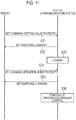
- the first command (that is, the SET command) can contain an operation mode property indicating an operation mode of the storage battery 120 in addition to the setting value property indicating a setting value of the charging/discharging amount of the storage battery 120.
- the setting value property is contained in the first command that is transmitted earlier than the first command containing the operation mode property.
- the PCS 130 controls the charging/discharging of the storage battery 120 on the basis of the operation mode property after receiving the first command containing the operation mode property without starting the charging/discharging of the storage battery 120 even when the first command containing the setting value property is received.
- Step S31 the EMS 160 transmits the SET command containing the setting value property to the PCS 130.
- Step S32 the PCS 130 transmits the SET response command with respect to the SET command to the EMS 160.
- Step S33 the PCS 130 receives the SET command containing the setting value property, but is on standby without starting the charging/discharging of the storage battery 120.
- Step S34 the EMS 160 transmits the SET command containing the operation mode property to the PCS 130.
- Step S36 the PCS 130 controls the charging/discharging of the storage battery 120 on the basis of the operation mode property.
- the PCS 130 enables the setting value property received in Step S31 on the basis of the operation mode property.
- the enabling is to perform the charging/discharging of the storage battery 120 according to the charging/discharging amount indicated by the setting value property.
- the PCS 130 may ignore the setting value property without enabling when the operation mode property and the setting value property are contradictable similarly to a case where the setting value property indicates the discharging amount in spite of the fact that the operation mode property indicates a charging mode.
- the first command (that is, the SET command) may contain the operation mode property indicating the operation mode of the storage battery 120 in addition to the setting value property indicating the setting value of the charging/discharging amount of the storage battery 120.
- the setting value property is contained in the first command containing the operation mode property.
- Step 41 the EMS 160 transmits the SET command that contains the operation mode property and the setting value property to the PCS 130.
- Step S42 the PCS 130 transmits the SET response command with respect to the SET command to the EMS 160.
- Step S43 the PCS 130 controls the charging/discharging of the storage battery 120 on the basis of the operation mode property. Further, the PCS 130 performs the charging/discharging of the storage battery 120 according to the charging/discharging amount that is indicated by the setting value property.
- the PCS 130 may ignore the setting value property when the operation mode property and the setting value property are contradictable similarly to a case where the setting value property indicates the discharging amount in spite of the fact that the operation mode property indicates a charging mode, and may control the charging/discharging of the storage battery 120 on the basis of the operation mode property.
- the embodiment is not limited to such a configuration. Any format may be used as long as the predetermined format is a standard format used in the facility 100.
- the response command may be the information notification command containing the INF command.
- the PCS 130 may transmit the information notification command containing the variable property to the EMS 160 when a predetermined condition is satisfied.
- the case where the predetermined condition is satisfied may be a case where the amount of residual charged power of the storage battery 120 is greater than a predetermined threshold, or may be a case where the amount of residual charged power of the storage battery 120 is less than the predetermined threshold.
- the case where the predetermined condition is satisfied may be a case where a value indicated by the variable property is rewritten by a third person. For example, when the SET command containing the variable property is received two times, the INF command containing the variable property may be transmitted in response to the second reception of the SET command.
- the PCS 130 (multi-PCS) that controls the outputs of the solar cell 110 and the storage battery 120 has been exemplified.
- the PCS 130 may be a PCS that controls the output of the storage battery 120.
- the PCS has been exemplified that controls the storage battery 120 as an equipment.
- the equipment may be a PCS that controls the output of the distributed power source such as the solar cell 110 and a fuel cell.
- the equipment may be the load 150 such as an air conditioner, a lighting device, a refrigerator, and a television.
- the properties of the first command and the second command may contain a variable property indicating a variable that can be changed according to the operation of the equipment.
- the storage battery 120 may be a storage battery provided in the facility 100, or may be a storage battery provided in an electric vehicle (EV).
- EV electric vehicle
- the communication device 132 forms part of the PCS that controls the storage battery 120, but the embodiment is not limited to the configuration.
- the communication device 132 may be a remote controller that is installed separately from the conversion device 131.
- the remote controller may be considered to form part of the PCS that controls the storage battery 120.
- the equipment managed by the management device (the EMS 160) may be a remote controller.
- the first communication unit 132A and the second communication unit 132B may be configured integrally.
- the first communication unit 132A may also function as the second communication unit 132B.
Landscapes
- Engineering & Computer Science (AREA)
- Power Engineering (AREA)
- Computer Networks & Wireless Communication (AREA)
- Signal Processing (AREA)
- Remote Monitoring And Control Of Power-Distribution Networks (AREA)
- Supply And Distribution Of Alternating Current (AREA)
- Selective Calling Equipment (AREA)
- Charge And Discharge Circuits For Batteries Or The Like (AREA)
Abstract
Description
- The invention relates to a management system, a management method, an equipment, and a management device.
- In recent years, there is provided a management system that includes an equipment and a management device that manages the equipment (for example, Patent Literature 1). The equipment is an electrical appliance such as an air conditioner and a lighting device, and a distributed power source such as a solar cell, a storage battery, and a fuel power generation device. The management device is called, for example, Home Energy Management System (HEMS), Store Energy Management System (SEMS), Building Energy Management System (BEMS), Factory Energy Management System (FEMS), and Cluster/Community Energy Management System (CEMS).
- In order to popularize the management system, the communication standardization between the equipment and the management device is effective, and an attempt to standardize the communication is being made.
- Patent Literature 1:
JP 2010-128810 A - A management system includes an equipment and a management device. The management device includes a transmitter configured to transmit a first command to the equipment to instruct an operation of the equipment. The equipment includes a controller configured to control an operation of the equipment according to the first command, and a transmitter configured to transmit a response command containing a property indicating a state of the equipment to the management device. A property of the first command includes a variable property indicating a variable that can be changed by an operation of the equipment. The controller keeps a variable indicated by the variable property without any change when the operation instructed by the first command is kept continuous. The transmitter provided in the equipment transmits the response command containing a specific value as the variable property to specify whether the operation is performed according to the first command.
- A management method includes Step A of transmitting a first command from a management device to an equipment to instruct an operation of the equipment, Step B of controlling the operation of the equipment according to the first command by the equipment, and Step C of transmitting a response command from the equipment to the management device, the response command containing a property that indicates a state of the equipment. A property of the first command includes a variable property indicating a variable that can be changed by an operation of the equipment. Step B includes a step of keeping a variable indicated by the variable property without any change when the operation instructed by the first command is kept continuous. Step C includes a step of transmitting the response command containing, as the variable property, a specific value to specify whether the operation is performed according to the first command.
- An equipment is managed by a management device. The equipment includes a controller configured to control an operation of the equipment according to a first command that is received from the management device, and a transmitter configured to transmit a response command containing a property indicating a state of the equipment to the management device. A property of the first command includes a variable property indicating a variable that can be changed by an operation of the equipment. The controller keeps a variable indicated by the variable property without any change when the operation instructed by the first command is kept continuous. The transmitter provided in the equipment transmits the response command containing a specific value as the variable property to specify whether the operation is performed according to the first command.
- A management device manages an equipment. The management device includes a transmitter configured to transmit a first command to the equipment to instruct an operation of the equipment, and a receiver configured to receive a response command containing a property indicating a state of the equipment from the equipment. A property of the first command includes a variable property indicating a variable that can be changed by an operation of the equipment. The variable indicated by the variable property is kept without any change when the operation instructed by the first command is kept continuous. The receiver receives the response command containing a specific value as the variable property to specify whether the operation is performed according to the first command.
-
-
Fig. 1 is a diagram illustrating amanagement system 1 according to an embodiment. -
Fig. 2 is a diagram illustrating acommunication device 132 according to the embodiment. -
Fig. 3 is a diagram illustrating anEMS 160 according to the embodiment. -
Fig. 4 is a diagram illustrating an example of a SET command according to the embodiment. -
Fig. 5 is a diagram illustrating an example of a SET response command according to the embodiment. -
Fig. 6 is a diagram illustrating an example of the SET command according to the embodiment. -
Fig. 7 is a diagram illustrating an example of the SET response command according to the embodiment. -
Fig. 8 is a sequence diagram illustrating a management method according to the embodiment. -
Fig. 9 is a sequence diagram illustrating a management method according to the embodiment. -
Fig. 10 is a sequence diagram illustrating a management method according to the embodiment. -
Fig. 11 is a sequence diagram illustrating a management method according to a first modification. -
Fig. 12 is a sequence diagram illustrating a management method according to the first modification. - Hereinafter, embodiments will be described with reference to the drawings. In the following description of the drawings, the portions identical with or similar to each other will be attached with the same or similar symbol.
- However, the drawings are schematically illustrated, and a ratio of each dimension may be different from the actual ratio. Therefore, specific dimensions should be determined with reference to the following description. Even in the drawings, there are included portion having a different relation of dimensions and a different ratio.
- In the following, a management system according to the embodiment will be described. As illustrated in
Fig. 1 , amanagement system 1 includes afacility 100 and anexternal server 400. Thefacility 100 includes arouter 200. Therouter 200 is connected to theexternal server 400 through anetwork 300. Therouter 200 forms a local area network, and is connected to the respective devices (for example, acommunication device 132 of aPCS 130, aload 150, an EMS 160, adisplay device 170, etc.). InFig. 1 , the solid line represents a power line, and the dotted line represents a signal line. Further, the invention is not limited to the above configuration, and the power line may transmit a signal. - The
facility 100 includes asolar cell 110, astorage battery 120, thePCS 130, adistribution board 140, theload 150, the EMS 160, and thedisplay device 170. - The
solar cell 110 is a device that generates power according to light receiving. Thesolar cell 110 outputs the generated DC power. A power generating amount of thesolar cell 110 changes according to the amount of insolation irradiated to thesolar cell 110. In the embodiment, thesolar cell 110 is an example of a distributed power source of which the output is can be controlled on the basis of an output control designated from a provider. However, the invention is not limited to the above configuration, and thestorage battery 120 may be a distributed power source of which the output can be controlled on the basis of the output control designated from the provider. - The
storage battery 120 is a device that accumulates power. Thestorage battery 120 outputs the accumulated DC power. In the embodiment, thestorage battery 120 is an example of the distributed power source of which the output can be controlled on the basis of the output control designated from the provider. - The
PCS 130 is an example of a power conditioning system (PCS) that converts the output power from the distributed power source. In the embodiment, thePCS 130 includes a conversion device 131 and thecommunication device 132. - The conversion device 131 converts the DC power from the
solar cell 110 into an AC power, and converts the DC power from thestorage battery 120 into an AC power. Further, the conversion device 131 converts an AC power from apower grid 10 into a DC power. The conversion device 131 is connected to atrunk power line 10L (herein, a trunk power line 10LA and a trunk power line 10LB) connected to thepower grid 10 through afirst distribution board 140A, and connected to both of thesolar cell 110 and thestorage battery 120. The trunk power line 10LA is a power line that connects thepower grid 10 and thefirst distribution board 140A. The trunk power line 10LB is a power line that connects thefirst distribution board 140A and asecond distribution board 140B. Further, in this embodiment, the conversion device 131 will be described about a hybrid power conditioning system that is connected to thesolar cell 110 and thestorage battery 120, but the power condition system may be connected to each of thesolar cell 110 and thestorage battery 120. - The
communication device 132 is connected to the conversion device 131, receives various types of messages to the conversion device 131, and transmits various types of messages from the conversion device 131. For the communication between thecommunication device 132 and the conversion device 131, a protocol (for example, unique protocol) applied to thePCS 130 is used. - In the embodiment, the
communication device 132 is connected to therouter 200 in a wired or wireless manner. Thecommunication device 132 is connected to theexternal server 400 through therouter 200, and receives an output control message designating the output control of the distributed power source from theexternal server 400. Secondly, thecommunication device 132 is connected to theEMS 160 through therouter 200, and communicates with theEMS 160 as for a predetermined command of a predetermined format. The predetermined format is not particularly limited, and an ECHONET Lite system, a SEP2.0 system, or a KNX system may be used for example. - As the predetermined format, a format in conformity to the ECHONET Lite system will be described for example. In such a case, the predetermined command may be roughly classified into a request command, a request response command that is a response to the request command, or an information notification command. The request command is, for example, a SET command or a GET command. The request response command is, for example, a SET response command that is a response to the SET command, and a GET response command that is a response to the GET command. The information notification command is, for example, an INF command.
- The SET command is a command having a property that instructs a setting or an operation to the
PCS 130. The SET response command is a command indicating that the SET command is received. The GET command is a command containing a property indicating a state of thePCS 130, and acquires the state of thePCS 130. The GET response command is a command that contains a property indicating the state of thePCS 130, and contains information requested by the GET command. The INF command is a command that contains a property indicating the state of thePCS 130, and notifies the state of thePCS 130. - The
distribution board 140 is connected to thetrunk power line 10L. Thedistribution board 140 includes thefirst distribution board 140A and thesecond distribution board 140B. Thefirst distribution board 140A is connected to thepower grid 10 through the trunk power line 10LA, and connected to thesolar cell 110 and thestorage battery 120 through the conversion device 131. In addition, thefirst distribution board 140A controls the power output from the conversion device 131 and the power supplied from thepower grid 10 to make the power flow to the trunk power line 10LB. The power flowing from the trunk power line 10LB is distributed to the respective equipment (herein, theload 150 and the EMS 160) by thesecond distribution board 140B. - The
load 150 is an device that consumes the power supplied through the power line. For example, theload 150 includes a device such as an air conditioner, a lighting device, a refrigerator, and a television. Theload 150 may be a single device, or may be a plurality of devices. - The
EMS 160 is a device (EMS; Energy Management System) that manages power information indicating the power in thefacility 100. The power in thefacility 100 indicates the power flowing into thefacility 100, the power received by thefacility 100, or the power supplied from thefacility 100. Therefore, for example, theEMS 160 manages at least thePCS 130. - The
EMS 160 may control a power generating amount of thesolar cell 110, a charging amount of thestorage battery 120, and a discharging amount of thestorage battery 120. TheEMS 160 may be configured to be integrally to thedistribution board 140. TheEMS 160 is a device that is connected to thenetwork 300. The function of theEMS 160 may be provided by a cloud service through thenetwork 300. - In the embodiment, the
EMS 160 is connected to the respective equipment (for example, thecommunication device 132 of thePCS 130 and the load 150) through therouter 200, and communicates with the respective equipment as for a predetermined command of a predetermined format. - The
EMS 160 is connected to thedisplay device 170 through therouter 200, and communicates with thedisplay device 170. TheEMS 160 may communicate with thedisplay device 170 as for a predetermined command of a predetermined format. As described above, the predetermined format is a format in conformity to the ECHONET Lite system for example. - The
display device 170 displays the power information indicating the power in thefacility 100. Thedisplay device 170 is, for example, a smart phone, a tablet, a digital television, or a dedicated terminal. Thedisplay device 170 is connected to theEMS 160 in a wired or wireless manner, and communicates with theEMS 160. Thedisplay device 170 may communicate with theEMS 160 as for a predetermined command of a predetermined format. Thedisplay device 170 receives data necessary for the displaying of the power information from theEMS 160. - The
network 300 is a network that connects theEMS 160 and theexternal server 400. Thenetwork 300 may be the Internet. Thenetwork 300 may include a mobile communication network. In addition, thenetwork 300 may be a dedicated communication line, or may be a general communication line. For example, when the output of thesolar cell 110 is equal to or more than a predetermined output, a dedicated communication line is used as thenetwork 300 so as to perform the output control more reliably. - The
external server 400 is a server that is managed by the provider such as an electric power provider, a power transmission/distribution provider, or a retailer. For example, the provider designates the output control of the distributed power source. Specifically, theexternal server 400 transmits the output control message to instruct the output control of the distributed power source. Theexternal server 400 may transmit a command (DR; Demand Response) that is an instruction to suppress an amount of current from thepower grid 10 to thefacility 100. - The output control message includes a target output control level that indicates a level of the output control of the distributed power source (herein, the solar cell 110). The target output control level is determined according to the output (hereinafter, referred to as an equipment recognition output) that is recognized as the output capability (for example, rated output) of the PCS that controls the distributed power source. The target output control level may be displayed by an absolute value (for example, ○○ kW) that is determined according to the equipment recognition output, may be displayed by a relative value (for example, reduction by ○○ kW) with respect to the equipment recognition output, or may be displayed by a controlled rate (for example, ○○%) with respect to the equipment recognition output. Further, while the description has been made by the equipment recognition output, an equipment recognition capacity [kWh] may be employed.
- When the output capability of the distributed power source and the output capability of the PCS are different, the equipment recognition output is set to a small one in these output capabilities. When a plurality of PCSs is provided, the equipment recognition output is a sum of the output capabilities of the plurality of PCSs.
- In the embodiment, the output control message includes calendar information that indicates a schedule of the output control of the distributed power source. In the calendar information, the schedule of the output control of the distributed power source can be set at every 30 minutes. The calendar information may include a schedule of one day, may include a schedule of one month, or may include a schedule of one year.
- In the embodiment, a predetermined period of time may be determined as a maximum period of time when the output control of the distributed power source is performed. For example, the predetermined period of time may be several days in one year (days rule), or may be an accumulated time in one year (accumulated time rule). More specifically, the predetermined period of time may be 30 days in one year (30 days rule), or may be 360 hours in one year (360 hours rule). However, the predetermined period of time may be not determined (designation rule). These rules represent a type of the output control of the distributed power source according to the output control message.
- By the way, the above property includes a property indicating a variable (hereinafter, variable property) that can be changed by the operation of the equipment such as a charging amount setting value and a discharging amount setting value of the storage battery. In the following, the
PCS 130 will be mainly exemplified as an equipment. - Under such an assumption, a case will be considered where a second command (for example, the GET command) is transmitted after a first command (for example, the SET command) is transmitted, and the
EMS 160 acquires the variable property from thePCS 130. In such a case, when thePCS 130 transmits a variable changed by the operation of thePCS 130 according to the second command, it is not possible for theEMS 160 to ascertain whether thePCS 130 is operating according to the first command transmitted by itself. Therefore, thePCS 130 is configured not to change the variable indicated by the variable property until the operation instructed by the first command is completed. - However, the variable is not changed in the process of the
PCS 130. Therefore, even when theEMS 160 receives the response command to the second command, it is not possible for theEMS 160 to ascertain whether thePCS 130 is operating according to the first command. - Regarding such a problem, the following management is performed in the embodiment. The
EMS 160 transmits the first command to thePCS 130 to instruct the operation of thePCS 130, and transmits the second command to thePCS 130 to request the state of thePCS 130. ThePCS 130 controls the operation of thePCS 130 according to the first command. ThePCS 130 transmits the response command (for example, GET response command) that has a property indicating the state of thePCS 130 according to the second command to theEMS 160. The properties of the first command and the second command include a variable property indicating a variable that is changed according to the operation of thePCS 130. ThePCS 130 keeps the variable indicated by the variable property without any change until the operation instructed by the first command is completed. ThePCS 130 transmits the response command containing a specific value as the variable property to specify whether the operation is performed according to the first command. The response command is the request response command that contains the SET response command and the GET response command, or the information notification command that contains the INF command. - Herein, the specific value may include a first specific value indicating that the operation instructed by the first command is completed. In other words, when the operation instructed by the first command is completed, the
PCS 130 transmits the second command containing the variable property indicating the first specific value to theEMS 160. The first specific value may be different from the value that can be indicated by the variable property contained in the first command. The first specific value may be a value associated with the operation completion, or may be zero. - The specific value may contain a second specific value indicating that the operation instructed by the first command is released by a user. When the operation instructed by the first command is released by the user, the
PCS 130 transmits the second command containing the variable property indicating the second specific value to theEMS 160. The second specific value may be different to a value that can be indicated by the variable property contained in the first command. The second specific value may be a value associated with the operation release, or may be zero. - The specific value may include a third specific value indicating that the operation instructed by the first command is not operated or that the operation instructed by the first command is suspended. When the operation instructed by the first command is not operated, or when the operation instructed by the first command is suspended, the
PCS 130 transmits the second command containing the variable property indicating the third specific value to theEMS 160. The third specific value may be different from a value that is indicated by the variable property contained in the first command. The third specific value may be a value associated with the operation inexecution or the operation suspension, or may be zero. - Herein, the first specific value may be a value that is different from the second specific value and the third specific value. However, the first specific value may be the same value as the second specific value and the third specific value. Similarly, the second specific value may be a value different from the first specific value and the third specific value. However, the second specific value may be the same value as the first specific value and the third specific value. Similarly, the third specific value may be a value different from the first specific value and the second specific value. However, the third specific value may be the same value as the first specific value and the second specific value.
- In the following, a communication device according to an embodiment will be described. As illustrated in
Fig. 2 , thecommunication device 132 includes afirst communication unit 132A, asecond communication unit 132B, aninterface 132C, and acontroller 132D. Herein, the communication device 132 (that is, the PCS 130) is an example of the equipment. - The
first communication unit 132A receives the output control message instructing the output control of the distributed power source from theexternal server 400. In the embodiment, thefirst communication unit 132A receives the output control message from theexternal server 400 without going through theEMS 160. - The
second communication unit 132B communicates with theEMS 160 as for a predetermined command of a predetermined format. As described above, the predetermined format is a format in conformity to the ECHONET Lite system for example. Herein, the predetermined format used in the communication between the communication device 132 (thesecond communication unit 132B) and theEMS 160 may be different from the format used in the communication between the communication device 132 (thefirst communication unit 132A) and theexternal server 400. In addition, the predetermined format used in the communication between thesecond communication unit 132B (thesecond communication unit 132B) and theEMS 160 may be different from the format used in the communication between the communication device 132 (theinterface 132C) and the conversion device 131. - The
interface 132C is an interface with respect to the conversion device 131. Theinterface 132C may be a wired interface, or may be a wireless interface. For the communication between thecommunication device 132 and the conversion device 131, a protocol (for example, unique protocol) applied to thePCS 130 is used. - The
controller 132D is configured by a memory and a CPU, and controls thecommunication device 132. For example, thecontroller 132D controls the conversion device 131 using theinterface 132C so as to control the distributed power source according to the output control message. Thecontroller 132D acquires the state (for example, a power generating amount of thesolar cell 110, a charging amount of thestorage battery 120, and a discharging amount of the storage battery 120) of the conversion device 131 from the conversion device 131 using theinterface 132C. Thecontroller 132D generates a command to control the conversion device 131 on the basis of the command received from theEMS 160, and outputs the command to the conversion device 131 using theinterface 132C. - In the following, a management device according to an embodiment will be described. As illustrated in
Fig. 3 , theEMS 160 includes acommunication unit 161 and acontroller 162. - The
communication unit 161 communicates with thecommunication device 132 as for a predetermined command of a predetermined format. As described above, the predetermined format is a format in conformity to the ECHONET Lite system for example. - The
controller 162 is configured by a memory and a CPU, and controls theEMS 160. Thecontroller 162 may control the power generating amount of thesolar cell 110, a charging amount of thestorage battery 120, and a discharging amount of thestorage battery 120. - In the following, a message format according to an embodiment will be described. Herein, the description will be given about a case where the predetermined format is a format in conformity to the ECHONET Lite system.
- As illustrated in
Fig. 4 , a SET command M510 includes a header M511, a code M512, and a target property M513. In the embodiment, the SET command M510 is an example of the first command to instruct the operation of thePCS 130, and is a command transmitted from theEMS 160 to thePCS 130. - The header M511 is information indicating a destination of the SET command M510. The code M512 is information indicating a type of the message containing the code M512. Herein, the code M512 is information indicating that the message containing the code M512 is a SET command.
- The target property M513 contains a property indicating an operation that is instructed to the
PCS 130 by theEMS 160. Such a property includes a variable property indicating a variable that is changed according to the operation of thePCS 130 for example. As the variable property, there is a setting value property that indicates a setting value of the charging/discharging amount of thestorage battery 120. The setting value of the charging/discharging amount collectively refers to as the setting value of the charging amount or the setting value of the discharging amount. The setting value of the charging/discharging amount may be either one of these two values or may be both of these two values. The setting value of the charging amount and the setting value of the discharging amount may contain information containing a type of power. The type of power is an alternating current (AC) or a direct current (DC). - The setting value property may be a property that designates a watt hour (Wh) of the charging or the discharging for example, or may be a property that designates a capacity (Ah) of the charging or the discharging. Further, the setting value designated by the setting value property may be an instantaneous power (W) of the charging or the discharging.
- As illustrated in
Fig. 5 , a SET response command M520 includes a header M521, a code M522, and a response content M523. In the embodiment, the SET response command M520 is an example of the command transmitted from thePCS 130 to theEMS 160 according to the command received from theEMS 160. - The header M521 is information indicating a destination of the SET response command M520. The code M522 is information indicating a type of the message containing the code M522. Herein, the code M522 is information indicating that the message containing the code M522 is a SET response command. The response content M523 includes information indicating that the SET command is received. Such information may be a copy of the property contained in the SET command, or may be an acknowledgement (ACK). In addition, such information is not limited, and may be a response (Selective ACK) intending that only some data is correctly received.
- As illustrated in
Fig. 6 , a GET command M610 includes a header M611, a code M612, and a target property M613. In the embodiment, the GET command M610 is an example of the second command to request the state of thePCS 130, and an example of the command transmitted from theEMS 160 to thePCS 130. - The header M611 is information indicating a destination of the GET command M610. The code M612 is information indicating a type of the message containing the code M612. Herein, the code M612 is information indicating that the message containing the code M612 is the GET command. The target property M613 includes a property that the
EMS 160 needs to know. Such a property includes the variable property similarly to the SET command for example. As the variable property, there is a setting value property that indicates a setting value of the charging/discharging amount of thestorage battery 120 similarly to the SET command. - As illustrated in
Fig. 7 , a GET response command M620 includes a header M621, a code M622, and a response content M623. In the embodiment, the GET response command M620 is an example of the command transmitted from thePCS 130 to theEMS 160 according to the command received from theEMS 160. - The header M621 is information indicating a destination of the GET response command M620. The code M622 is information indicating a type of the message containing the code M622. Herein, the code M622 is information indicating that the message containing the code M622 is the GET response command. The response content M623 includes a property that is requested by the GET command. Such a property includes the variable property similarly to the SET command and the GET command for example. As the variable property, similarly to the SET command and the GET command, there is a setting value property that indicates a setting value of the charging/discharging amount of the
storage battery 120. - Herein, as described above, the GET response command includes a specific value as the variable property to specify whether the operation is performed according to the SET command.
- In the following, a management method according to the embodiment will be described. Herein, the description will be given about a case where the predetermined format used in the communication between the PCS 130 (the communication device 132) and the
EMS 160 is a format in conformity to the ECHONET Lite system. A case where the SET command and the GET command contain the setting value property will be described. - First, the description will be given about a case where the
PCS 130 starts the operation instructed by the SET command, and thePCS 130 completes the operation instructed by the SET command with reference toFig. 8 . - In Step S11, the
EMS 160 transmits the SET command containing the setting value property to thePCS 130. - In Step S12, the
PCS 130 transmits the SET response command with respect to the SET command to theEMS 160. - In Step S13, the
PCS 130 starts the operation instructed by the SET command. Herein, the SET command contains the setting value property, and thePCS 130 starts the control of the charging/discharging of thestorage battery 120. For example, when the setting value property is a property to instruct the charging amount, thePCS 130 starts the charging of thestorage battery 120. On the other hand, when the setting value property is a property to instruct the discharging amount, thePCS 130 starts the discharging of thestorage battery 120. However, thePCS 130 keeps the variable indicated by the variable property contained in the SET command without any change until the control of the charging/discharging of thestorage battery 120 instructed by the SET command is completed. - In Step S14, the
EMS 160 transmits the GET command containing the setting value property to thePCS 130. - In Step S15, the
PCS 130 transmits the GET response command with respect to the GET command to theEMS 160. Herein, since the variable indicated by the variable property contained in the SET command is kept without any change, thePCS 130 transmits the GET response command containing a copy of the variable indicated by the SET command as the variable property. With this configuration, theEMS 160 can ascertain that thePCS 130 receives the SET command transmitted in Step S11. However, theEMS 160 hardly ascertains whether thePCS 130 is actually operated according to the SET command transmitted in Step S11. - In Step S16, the
PCS 130 completes the operation instructed by the SET command. Herein, thePCS 130 completes the control of the charging/discharging of thestorage battery 120. Since the control of the charging/discharging of thestorage battery 120 instructed by the SET command is completed, the variable indicated by the variable property contained in the SET command may be changed by thePCS 130. Herein, thePCS 130 transitions from the control state of the charging/discharging to a standby state as the operation instructed by the SET command is completed. - In Step S17, the
EMS 160 transmits the GET command containing the setting value property to thePCS 130. - In Step S18, the
PCS 130 transmits the GET response command with respect to the GET command to theEMS 160. ThePCS 130 transmits the GET response command containing the variable property indicating the first specific value that indicates that the operation instructed by the SET command is completed. The first specific value may be different from a value that is indicated by the variable property contained in the SET command. The first specific value may be a value associated with the operation completion, or may be zero. - Secondly, the description will be given with reference to
Fig. 9 about a case where thePCS 130 starts the operation instructed by the SET command, and the operation instructed by the SET command is released or suspended. InFig. 9 , the same processes as those ofFig. 8 will be attached with the same Step symbol. The processes of Steps S11 to S13 are the same as those ofFig. 8 , and the description thereof will be omitted. - In Step S21, the operation instructed by the SET command is released by the user. For example, the operation release may be an event in which the user releases the operation instructed by the SET command according to a provider's request. Alternatively, the operation instructed by the SET command is suspended. For example, the suspension of the operation may be an event in which an amount of residual charged power of the
storage battery 120 is greater than a predetermined threshold when the setting value property is a property instructing the charging amount. Alternatively, the suspension of the operation may be an event in which the amount of residual charged power of thestorage battery 120 is less than the threshold when the setting value property is a property instructing the discharging amount. Alternatively, the suspension of the operation may be failure or maintenance of any one of thestorage battery 120 and thePCS 130. The suspension of the operation may be a blackout of thepower grid 10. Alternatively, the suspension of the operation may be an event in which the operation designated by the SET command is released by the provider. - In Step S22, the
EMS 160 transmits the GET command containing the setting value property to thePCS 130. - In Step S23, the
PCS 130 transmits the GET response command with respect to the GET command to theEMS 160. ThePCS 130 transmits the GET response command containing the variable property indicating the second specific value that indicates that the operation instructed by the SET command is released. The second specific value may be different from a value that is indicated by the variable property contained in the SET command. The second specific value may be a value associated with the operation release, or may be zero. Alternatively, thePCS 130 transmits the GET response command containing the variable property indicating the third specific value that indicates that the operation instructed by the SET command is suspended. The third specific value may be different from a value that is indicated by the variable property contained in the SET command. The third specific value may be a value associated with the operation suspension, or may be zero. - Thirdly, the description will be given with reference to
Fig. 10 about a case where thePCS 130 does not perform the operation instructed by the SET command. InFig. 10 , the same processes as those ofFig. 9 will be attached with the same Step symbol. The processes illustrated inFig. 10 are the same as those ofFig. 9 except that the processes of Steps S13 and S21 are not performed. - In Step S23, the
PCS 130 transmits the GET response command with respect to the GET command to theEMS 160 similarly toFig. 9 . However, inFig. 10 , thePCS 130 transmits the GET response command containing the variable property indicating the third specific value that indicates that the operation instructed by the SET command is not performed. The third specific value may be different from a value that is indicated by the variable property contained in the SET command. The third specific value may be a value associated with the operation inexecution, or may be zero. - For example, the inexeuction of the operation may be an event in which the operation designated by the SET command is restricted by the user. Alternatively, the inexeuction of the operation may be an event in which the operation designated by the SET command is restricted by the provider. Alternatively, the operation inexecution may be an event in which the operation does not start even though a predetermined period of time elapses after the SET command is received.
- In the embodiment, when the properties of the SET command and the GET command include the variable property indicating a variable that can be changed according to the operation of the
PCS 130, thePCS 130 keeps the variable indicated by the variable property without any change until the operation instructed by the SET command is completed. ThePCS 130 transmits the GET response command containing a specific value as the variable property to theEMS 160 to specify whether the operation is performed according to the SET command. With this configuration, theEMS 160 can determine whether thePCS 130 is actually operated according to the SET command on the basis of the specific value contained in the GET response command. For example, theEMS 160 can determine the operation completion, the operation release, the operation suspension, or the operation inexecution. - In the following, a first modification of the embodiment will be described. In the following, the first modification of the embodiment will be described.
- In the first modification, the first command (that is, the SET command) can contain an operation mode property indicating an operation mode of the
storage battery 120 in addition to the setting value property indicating a setting value of the charging/discharging amount of thestorage battery 120. The setting value property is contained in the first command that is transmitted earlier than the first command containing the operation mode property. - In such a case, the
PCS 130 controls the charging/discharging of thestorage battery 120 on the basis of the operation mode property after receiving the first command containing the operation mode property without starting the charging/discharging of thestorage battery 120 even when the first command containing the setting value property is received. - For example, as illustrated in
Fig. 11 , in Step S31, theEMS 160 transmits the SET command containing the setting value property to thePCS 130. - In Step S32, the
PCS 130 transmits the SET response command with respect to the SET command to theEMS 160. - In Step S33, the
PCS 130 receives the SET command containing the setting value property, but is on standby without starting the charging/discharging of thestorage battery 120. - In Step S34, the
EMS 160 transmits the SET command containing the operation mode property to thePCS 130. - In Step S35, the
PCS 130 transmits the SET response command with respect to the SET command to theEMS 160. - In Step S36, the
PCS 130 controls the charging/discharging of thestorage battery 120 on the basis of the operation mode property. ThePCS 130 enables the setting value property received in Step S31 on the basis of the operation mode property. The enabling is to perform the charging/discharging of thestorage battery 120 according to the charging/discharging amount indicated by the setting value property. - However, the
PCS 130 may ignore the setting value property without enabling when the operation mode property and the setting value property are contradictable similarly to a case where the setting value property indicates the discharging amount in spite of the fact that the operation mode property indicates a charging mode. - In the following, a second modification of the embodiment will be described. In the following, the second modification of the embodiment will be described.
- In the second modification, the first command (that is, the SET command) may contain the operation mode property indicating the operation mode of the
storage battery 120 in addition to the setting value property indicating the setting value of the charging/discharging amount of thestorage battery 120. The setting value property is contained in the first command containing the operation mode property. - For example, as illustrated in
Fig. 12 , in Step 41, theEMS 160 transmits the SET command that contains the operation mode property and the setting value property to thePCS 130. - In Step S42, the
PCS 130 transmits the SET response command with respect to the SET command to theEMS 160. - In Step S43, the
PCS 130 controls the charging/discharging of thestorage battery 120 on the basis of the operation mode property. Further, thePCS 130 performs the charging/discharging of thestorage battery 120 according to the charging/discharging amount that is indicated by the setting value property. - However, the
PCS 130 may ignore the setting value property when the operation mode property and the setting value property are contradictable similarly to a case where the setting value property indicates the discharging amount in spite of the fact that the operation mode property indicates a charging mode, and may control the charging/discharging of thestorage battery 120 on the basis of the operation mode property. - The invention has been described using the above-described embodiment. However, it should be understood that the explanation and drawings representing part of the disclosure do not limit the invention. Various alternative embodiments, examples, and operating techniques may be apparent to a person skilled in the art from the disclosure.
- In the embodiment, the description has been described about a case where the predetermined format used in the communication between the
communication device 132 and theEMS 160 is a format in conformity to the ECHONET Lite system. However, the embodiment is not limited to such a configuration. Any format may be used as long as the predetermined format is a standard format used in thefacility 100. - In the embodiment, a case where the response command is the request response command containing the GET response command has been exemplified. However, the embodiment is not limited to such a configuration. The response command may be the information notification command containing the INF command. For example, the
PCS 130 may transmit the information notification command containing the variable property to theEMS 160 when a predetermined condition is satisfied. The case where the predetermined condition is satisfied may be a case where the amount of residual charged power of thestorage battery 120 is greater than a predetermined threshold, or may be a case where the amount of residual charged power of thestorage battery 120 is less than the predetermined threshold. Further, the case where the predetermined condition is satisfied may be a case where a value indicated by the variable property is rewritten by a third person. For example, when the SET command containing the variable property is received two times, the INF command containing the variable property may be transmitted in response to the second reception of the SET command. - In the embodiment, the PCS 130 (multi-PCS) that controls the outputs of the
solar cell 110 and thestorage battery 120 has been exemplified. However, the embodiment is not limited to such a configuration. ThePCS 130 may be a PCS that controls the output of thestorage battery 120. - In the embodiment, the PCS has been exemplified that controls the
storage battery 120 as an equipment. However, the embodiment is not limited to such a configuration. The equipment may be a PCS that controls the output of the distributed power source such as thesolar cell 110 and a fuel cell. The equipment may be theload 150 such as an air conditioner, a lighting device, a refrigerator, and a television. In other words, regardless of the type of the equipment, the properties of the first command and the second command may contain a variable property indicating a variable that can be changed according to the operation of the equipment. - In the embodiment, while not particularly limited, the
storage battery 120 may be a storage battery provided in thefacility 100, or may be a storage battery provided in an electric vehicle (EV). - In the embodiment, the
communication device 132 forms part of the PCS that controls thestorage battery 120, but the embodiment is not limited to the configuration. Thecommunication device 132 may be a remote controller that is installed separately from the conversion device 131. The remote controller may be considered to form part of the PCS that controls thestorage battery 120. The equipment managed by the management device (the EMS 160) may be a remote controller. - In the embodiment, the description has been given about a case where the
first communication unit 132A and thesecond communication unit 132B are configured separately. However, thefirst communication unit 132A and thesecond communication unit 132B may be configured integrally. In other words, thefirst communication unit 132A may also function as thesecond communication unit 132B. - Further, priority is claimed on Japanese Patent Application No.
2016-66750 filed on March 29, 2016
Claims (16)
- A management system, comprising:an equipment; anda management device, whereinthe management device includesa transmitter configured to transmit a first command to the equipment to instruct an operation of the equipment,the equipment includesa controller configured to control an operation of the equipment according to the first command, anda transmitter configured to transmit a response command containing a property indicating a state of the equipment to the management device, whereina property of the first command includes a variable property indicating a variable that can be changed by an operation of the equipment,the controller is configured to keep a variable indicated by the variable property without any change when the operation instructed by the first command is kept continuous, andthe transmitter provided in the equipment is configured to transmit the response command containing a specific value as the variable property to specify whether the operation is performed according to the first command.
- The management system according to claim 1, wherein
the transmitter provided in the equipment is configured to transmit an information notification command as the response command containing the specific value as the variable property when a predetermined condition is satisfied. - The management system according to claim 1 or 2, wherein
the transmitter provided in the equipment is configured to transmit a request response command as the response command containing the specific value as the variable property when a second command requesting the state of the equipment is received. - The management system according to any one of claims 1 to 3, wherein
the transmitter provided in the equipment is configured to transmit a command containing the variable kept without change by the controller to the management device when the operation instructed by the first command is kept continuous. - The management system according to any one of claims 1 to 4, wherein
the specific value includes a first specific value indicating that the operation instructed by the first command is completed. - The management system according to any one of claims 1 to 5, wherein
the specific value includes a second specific value indicating that the operation instructed by the first command is released by a user. - The management system according to any one of claims 1 to 6, wherein
the specific value includes a third specific value indicating that the operation instructed by the first command is not performed, or that the operation instructed by the first command is suspended. - The management system according to any one of claims 1 to 7, wherein
the specific value includes a fourth specific value indicating that the operation instructed by the first command is not completed within a predetermined period of time. - The management system according to any one of claims 1 to 8, wherein
the specific value includes zero. - The management system according to any one of claims 1 to 9, wherein
the equipment is a power conditioning system that performs charging/discharging of a storage battery,
the first command contains a setting value property indicating a setting value of a charging/discharging amount of the storage battery as the variable property, and
the controller is configured to control the charging/discharging of the storage battery on the basis of the setting value property when the first command contains the setting value property. - The management system according to any one of claims 1 to 9, wherein
the equipment is a power conditioning system that performs charging/discharging of a storage battery,
the first command is capable of containing a setting value property indicating a setting value of a charging/discharging amount of the storage battery as the variable property, and of containing an operation mode property indicating an operation mode of the storage battery,
the setting value property is contained in the first command that is transmitted earlier than the first command containing the operation mode property, and
the controller is configured to control the charging/discharging of the storage battery on the basis of the operation mode property after the first command containing the operation mode property is received even when the first command containing the setting value property is received. - The management system according to claim 11, wherein
the controller is configured to enable the setting value property when charging/discharging of the storage battery is controlled on the basis of the operation mode property. - The management system according to any one of claims 1 to 9, wherein
the equipment is a power conditioning system that performs charging/discharging of a storage battery,
the first command is capable of containing a setting value property indicating a setting value of a charging/discharging amount of the storage battery as the variable property, and of containing an operation mode property indicating an operation mode of the storage battery, and
the setting value property is contained in the first command containing the operation mode property. - A management method, comprisingStep A of transmitting a first command from a management device to an equipment to instruct an operation of the equipment;Step B of controlling the operation of the equipment according to the first command by the equipment; andStep C of transmitting a response command from the equipment to the management device, the response command containing a property that indicates a state of the equipment, whereina property of the first command includes a variable property indicating a variable that can be changed by an operation of the equipment,
Step B includes a step of keeping a variable indicated by the variable property without any change when the operation instructed by the first command is kept continuous, and
Step C includes a step of transmitting the response command containing, as the variable property, a specific value to specify whether the operation is performed according to the first command. - An equipment that is managed by a management device, comprising:a controller configured to control an operation of the equipment according to a first command that is received from the management device; anda transmitter configured to transmit a response command containing a property indicating a state of the equipment to the management device, whereina property of the first command includes a variable property indicating a variable that can be changed by an operation of the equipment,the controller is configured to keep a variable indicated by the variable property without any change when the operation instructed by the first command is kept continuous, andthe transmitter is configured to transmit the response command containing a specific value as the variable property to specify whether the operation is performed according to the first command.
- A management device that manages an equipment, comprising:a transmitter configured to transmit a first command to the equipment to instruct an operation of the equipment; anda receiver configured to receive a response command containing a property indicating a state of the equipment from the equipment, whereina property of the first command includes a variable property indicating a variable that can be changed by an operation of the equipment,the variable indicated by the variable property is kept without any change when the operation instructed by the first command is kept continuous, andthe receiver is configured to receive the response command containing a specific value as the variable property to specify whether the operation is performed according to the first command.
Applications Claiming Priority (2)
| Application Number | Priority Date | Filing Date | Title |
|---|---|---|---|
| JP2016066750 | 2016-03-29 | ||
| PCT/JP2017/012503 WO2017170464A1 (en) | 2016-03-29 | 2017-03-28 | Management system, management method, apparatus, and management device |
Publications (2)
| Publication Number | Publication Date |
|---|---|
| EP3439315A1 true EP3439315A1 (en) | 2019-02-06 |
| EP3439315A4 EP3439315A4 (en) | 2019-08-14 |
Family
ID=59965642
Family Applications (1)
| Application Number | Title | Priority Date | Filing Date |
|---|---|---|---|
| EP17775001.5A Pending EP3439315A4 (en) | 2016-03-29 | 2017-03-28 | Management system, management method, apparatus, and management device |
Country Status (5)
| Country | Link |
|---|---|
| US (1) | US11056911B2 (en) |
| EP (1) | EP3439315A4 (en) |
| JP (1) | JP7122252B2 (en) |
| CN (1) | CN108886644B (en) |
| WO (1) | WO2017170464A1 (en) |
Families Citing this family (5)
| Publication number | Priority date | Publication date | Assignee | Title |
|---|---|---|---|---|
| US10978877B2 (en) * | 2016-05-24 | 2021-04-13 | Kyocera Corporation | Management system, management method, power conversion apparatus, and management apparatus |
| JP2020124022A (en) * | 2019-01-29 | 2020-08-13 | 京セラ株式会社 | Power management device, power storage device, and power management method |
| JP2022050576A (en) * | 2019-01-29 | 2022-03-30 | 京セラ株式会社 | Power management device, power storage device, and power management method |
| CN111314064B (en) * | 2020-01-20 | 2021-09-17 | 中国银联股份有限公司 | Mobile phone shield state management method, TSM platform server and storage medium |
| JP7316433B2 (en) * | 2022-01-11 | 2023-07-27 | 京セラ株式会社 | Power management device, power storage device, and power management method |
Family Cites Families (23)
| Publication number | Priority date | Publication date | Assignee | Title |
|---|---|---|---|---|
| JP2000308272A (en) * | 1999-04-19 | 2000-11-02 | Yuasa Corp | Charge controller of storage battery device, and charge control method, and computer-readable storage medium having stored program for controlling charge of storage battery device |
| JP2001251780A (en) * | 2000-03-07 | 2001-09-14 | Sharp Corp | Charger for secondary cell |
| JP2006209462A (en) * | 2005-01-28 | 2006-08-10 | Kyocera Corp | Terminal device |
| CA2605841C (en) * | 2005-04-25 | 2012-06-19 | Lg Electronics Inc. | Reader control system |
| US8103389B2 (en) * | 2006-05-18 | 2012-01-24 | Gridpoint, Inc. | Modular energy control system |
| US9002761B2 (en) * | 2008-10-08 | 2015-04-07 | Rey Montalvo | Method and system for automatically adapting end user power usage |
| US20150276253A1 (en) * | 2008-10-08 | 2015-10-01 | Rey Montalvo | Method and system for fully automated enterprise control of local power usage |
| JP5270315B2 (en) | 2008-11-27 | 2013-08-21 | 株式会社日立製作所 | Automatic meter reading method, automatic meter reading system, automatic meter reading device, and smart meter |
| US8975778B2 (en) * | 2009-07-30 | 2015-03-10 | Lutron Electronics Co., Inc. | Load control system providing manual override of an energy savings mode |
| JP5062273B2 (en) * | 2010-03-12 | 2012-10-31 | ダイキン工業株式会社 | Energy management system |
| JP5583781B2 (en) | 2010-10-15 | 2014-09-03 | 三洋電機株式会社 | Power management system |
| US8983669B2 (en) * | 2012-07-31 | 2015-03-17 | Causam Energy, Inc. | System, method, and data packets for messaging for electric power grid elements over a secure internet protocol network |
| US9208676B2 (en) * | 2013-03-14 | 2015-12-08 | Google Inc. | Devices, methods, and associated information processing for security in a smart-sensored home |
| JP5952416B2 (en) * | 2012-09-27 | 2016-07-13 | 京セラ株式会社 | Management method, control apparatus, and communication processing device |
| JP6028044B2 (en) | 2012-12-28 | 2016-11-16 | 日立アプライアンス株式会社 | Power control system, control device, and power control method |
| US9912157B2 (en) * | 2013-03-04 | 2018-03-06 | Nec Corporation | Energy management system and energy management method |
| JP6339318B2 (en) * | 2013-04-09 | 2018-06-06 | 京セラ株式会社 | Information device, control system, and control method |
| JP6076807B2 (en) * | 2013-04-09 | 2017-02-08 | 京セラ株式会社 | Information device, control device, control system, and control method |
| JP6151072B2 (en) | 2013-04-12 | 2017-06-21 | 京セラ株式会社 | CONTROL SYSTEM, CONTROL DEVICE, INFORMATION DEVICE, AND CONTROL METHOD |
| JP6073179B2 (en) * | 2013-04-25 | 2017-02-01 | 京セラ株式会社 | Control system, information device, and control method |
| JP2015026149A (en) * | 2013-07-25 | 2015-02-05 | 株式会社日立ソリューションズ | Billing device for charger |
| WO2015115571A1 (en) * | 2014-01-29 | 2015-08-06 | 京セラ株式会社 | Control device and control method |
| WO2018200854A1 (en) * | 2017-04-27 | 2018-11-01 | Johnson Controls Technology Company | Building energy system with predictive control |
-
2017
- 2017-03-28 JP JP2018508021A patent/JP7122252B2/en active Active
- 2017-03-28 CN CN201780021288.2A patent/CN108886644B/en active Active
- 2017-03-28 US US16/089,581 patent/US11056911B2/en active Active
- 2017-03-28 EP EP17775001.5A patent/EP3439315A4/en active Pending
- 2017-03-28 WO PCT/JP2017/012503 patent/WO2017170464A1/en active Application Filing
Also Published As
| Publication number | Publication date |
|---|---|
| US11056911B2 (en) | 2021-07-06 |
| EP3439315A4 (en) | 2019-08-14 |
| CN108886644A (en) | 2018-11-23 |
| WO2017170464A1 (en) | 2017-10-05 |
| US20200287408A1 (en) | 2020-09-10 |
| JP7122252B2 (en) | 2022-08-19 |
| JPWO2017170464A1 (en) | 2019-03-22 |
| CN108886644B (en) | 2021-05-28 |
Similar Documents
| Publication | Publication Date | Title |
|---|---|---|
| US11056911B2 (en) | Management system, management method, equipment, and management device | |
| EP3306771B1 (en) | Electric power conversion device, electric power management device, and electric power management method | |
| WO2018003408A1 (en) | Management method, management device, distributed power supply, and management system | |
| US10978877B2 (en) | Management system, management method, power conversion apparatus, and management apparatus | |
| JP6582091B2 (en) | Power conversion device, power management device, and power management method | |
| US11165280B2 (en) | Power management method, power management apparatus, power conversion apparatus, and power management system | |
| JP6328216B2 (en) | Management system, management method, device and management apparatus | |
| JP6640989B2 (en) | Management system, management method, power conversion device, and management device | |
| JP7153686B2 (en) | Display device, management device, and control method | |
| EP3306780B1 (en) | Power conversion device, power management device, and power management method |
Legal Events
| Date | Code | Title | Description |
|---|---|---|---|
| STAA | Information on the status of an ep patent application or granted ep patent |
Free format text: STATUS: THE INTERNATIONAL PUBLICATION HAS BEEN MADE |
|
| PUAI | Public reference made under article 153(3) epc to a published international application that has entered the european phase |
Free format text: ORIGINAL CODE: 0009012 |
|
| STAA | Information on the status of an ep patent application or granted ep patent |
Free format text: STATUS: REQUEST FOR EXAMINATION WAS MADE |
|
| 17P | Request for examination filed |
Effective date: 20180928 |
|
| AK | Designated contracting states |
Kind code of ref document: A1 Designated state(s): AL AT BE BG CH CY CZ DE DK EE ES FI FR GB GR HR HU IE IS IT LI LT LU LV MC MK MT NL NO PL PT RO RS SE SI SK SM TR |
|
| AX | Request for extension of the european patent |
Extension state: BA ME |
|
| STAA | Information on the status of an ep patent application or granted ep patent |
Free format text: STATUS: REQUEST FOR EXAMINATION WAS MADE |
|
| DAV | Request for validation of the european patent (deleted) | ||
| DAX | Request for extension of the european patent (deleted) | ||
| REG | Reference to a national code |
Ref country code: DE Ref legal event code: R079 Free format text: PREVIOUS MAIN CLASS: H04Q0009000000 Ipc: H02J0003140000 |
|
| A4 | Supplementary search report drawn up and despatched |
Effective date: 20190715 |
|
| RIC1 | Information provided on ipc code assigned before grant |
Ipc: H02J 13/00 20060101ALI20190709BHEP Ipc: H02J 3/32 20060101ALN20190709BHEP Ipc: H04Q 9/00 20060101ALI20190709BHEP Ipc: H04M 11/00 20060101ALI20190709BHEP Ipc: H02J 3/14 20060101AFI20190709BHEP Ipc: H02J 7/35 20060101ALI20190709BHEP |
|
| STAA | Information on the status of an ep patent application or granted ep patent |
Free format text: STATUS: EXAMINATION IS IN PROGRESS |
|
| 17Q | First examination report despatched |
Effective date: 20210507 |
|
| STAA | Information on the status of an ep patent application or granted ep patent |
Free format text: STATUS: EXAMINATION IS IN PROGRESS |
|
| P01 | Opt-out of the competence of the unified patent court (upc) registered |
Effective date: 20230508 |
|
| GRAP | Despatch of communication of intention to grant a patent |
Free format text: ORIGINAL CODE: EPIDOSNIGR1 |
|
| STAA | Information on the status of an ep patent application or granted ep patent |
Free format text: STATUS: GRANT OF PATENT IS INTENDED |
|
| INTG | Intention to grant announced |
Effective date: 20240726 |