EP3439244A1 - Modular element for a mixed network of an aircraft - Google Patents
Modular element for a mixed network of an aircraft Download PDFInfo
- Publication number
- EP3439244A1 EP3439244A1 EP18182086.1A EP18182086A EP3439244A1 EP 3439244 A1 EP3439244 A1 EP 3439244A1 EP 18182086 A EP18182086 A EP 18182086A EP 3439244 A1 EP3439244 A1 EP 3439244A1
- Authority
- EP
- European Patent Office
- Prior art keywords
- busbar
- aircraft
- modular element
- data links
- modular
- Prior art date
- Legal status (The legal status is an assumption and is not a legal conclusion. Google has not performed a legal analysis and makes no representation as to the accuracy of the status listed.)
- Granted
Links
- 238000004891 communication Methods 0.000 claims abstract description 66
- 239000013307 optical fiber Substances 0.000 claims description 15
- 238000003756 stirring Methods 0.000 claims description 10
- 101100334010 Drosophila melanogaster sotv gene Proteins 0.000 claims description 7
- 230000010354 integration Effects 0.000 claims description 4
- 239000004020 conductor Substances 0.000 description 35
- 238000006243 chemical reaction Methods 0.000 description 9
- 238000012986 modification Methods 0.000 description 6
- 230000004048 modification Effects 0.000 description 6
- 238000004519 manufacturing process Methods 0.000 description 5
- 230000003287 optical effect Effects 0.000 description 5
- 241001441732 Ostraciidae Species 0.000 description 4
- 230000000694 effects Effects 0.000 description 4
- 239000000835 fiber Substances 0.000 description 4
- 238000004513 sizing Methods 0.000 description 4
- 229910052782 aluminium Inorganic materials 0.000 description 3
- XAGFODPZIPBFFR-UHFFFAOYSA-N aluminium Chemical compound [Al] XAGFODPZIPBFFR-UHFFFAOYSA-N 0.000 description 3
- 239000012777 electrically insulating material Substances 0.000 description 3
- 238000002955 isolation Methods 0.000 description 3
- RYGMFSIKBFXOCR-UHFFFAOYSA-N Copper Chemical compound [Cu] RYGMFSIKBFXOCR-UHFFFAOYSA-N 0.000 description 2
- 229910052774 Proactinium Inorganic materials 0.000 description 2
- 241001080024 Telles Species 0.000 description 2
- 230000000712 assembly Effects 0.000 description 2
- 238000000429 assembly Methods 0.000 description 2
- 230000015556 catabolic process Effects 0.000 description 2
- 229910052802 copper Inorganic materials 0.000 description 2
- 239000010949 copper Substances 0.000 description 2
- 229940082150 encore Drugs 0.000 description 2
- 229910052745 lead Inorganic materials 0.000 description 2
- 229910052751 metal Inorganic materials 0.000 description 2
- 239000002184 metal Substances 0.000 description 2
- 239000006096 absorbing agent Substances 0.000 description 1
- 210000004027 cell Anatomy 0.000 description 1
- 239000002131 composite material Substances 0.000 description 1
- 238000009795 derivation Methods 0.000 description 1
- 238000013461 design Methods 0.000 description 1
- 238000011161 development Methods 0.000 description 1
- 238000006073 displacement reaction Methods 0.000 description 1
- 239000000428 dust Substances 0.000 description 1
- 238000000605 extraction Methods 0.000 description 1
- 238000003780 insertion Methods 0.000 description 1
- 230000037431 insertion Effects 0.000 description 1
- 238000009434 installation Methods 0.000 description 1
- 238000009413 insulation Methods 0.000 description 1
- 239000012212 insulator Substances 0.000 description 1
- 239000000463 material Substances 0.000 description 1
- 230000007935 neutral effect Effects 0.000 description 1
- 238000005204 segregation Methods 0.000 description 1
Images


Classifications
-
- H—ELECTRICITY
- H04—ELECTRIC COMMUNICATION TECHNIQUE
- H04L—TRANSMISSION OF DIGITAL INFORMATION, e.g. TELEGRAPHIC COMMUNICATION
- H04L12/00—Data switching networks
- H04L12/28—Data switching networks characterised by path configuration, e.g. LAN [Local Area Networks] or WAN [Wide Area Networks]
- H04L12/40—Bus networks
- H04L12/40006—Architecture of a communication node
-
- B—PERFORMING OPERATIONS; TRANSPORTING
- B64—AIRCRAFT; AVIATION; COSMONAUTICS
- B64D—EQUIPMENT FOR FITTING IN OR TO AIRCRAFT; FLIGHT SUITS; PARACHUTES; ARRANGEMENTS OR MOUNTING OF POWER PLANTS OR PROPULSION TRANSMISSIONS IN AIRCRAFT
- B64D47/00—Equipment not otherwise provided for
-
- H—ELECTRICITY
- H02—GENERATION; CONVERSION OR DISTRIBUTION OF ELECTRIC POWER
- H02J—CIRCUIT ARRANGEMENTS OR SYSTEMS FOR SUPPLYING OR DISTRIBUTING ELECTRIC POWER; SYSTEMS FOR STORING ELECTRIC ENERGY
- H02J13/00—Circuit arrangements for providing remote indication of network conditions, e.g. an instantaneous record of the open or closed condition of each circuitbreaker in the network; Circuit arrangements for providing remote control of switching means in a power distribution network, e.g. switching in and out of current consumers by using a pulse code signal carried by the network
-
- H—ELECTRICITY
- H04—ELECTRIC COMMUNICATION TECHNIQUE
- H04L—TRANSMISSION OF DIGITAL INFORMATION, e.g. TELEGRAPHIC COMMUNICATION
- H04L12/00—Data switching networks
- H04L12/28—Data switching networks characterised by path configuration, e.g. LAN [Local Area Networks] or WAN [Wide Area Networks]
- H04L12/46—Interconnection of networks
- H04L12/4604—LAN interconnection over a backbone network, e.g. Internet, Frame Relay
- H04L12/462—LAN interconnection over a bridge based backbone
- H04L12/4625—Single bridge functionality, e.g. connection of two networks over a single bridge
-
- H—ELECTRICITY
- H04—ELECTRIC COMMUNICATION TECHNIQUE
- H04L—TRANSMISSION OF DIGITAL INFORMATION, e.g. TELEGRAPHIC COMMUNICATION
- H04L67/00—Network arrangements or protocols for supporting network services or applications
- H04L67/01—Protocols
- H04L67/12—Protocols specially adapted for proprietary or special-purpose networking environments, e.g. medical networks, sensor networks, networks in vehicles or remote metering networks
-
- B—PERFORMING OPERATIONS; TRANSPORTING
- B64—AIRCRAFT; AVIATION; COSMONAUTICS
- B64D—EQUIPMENT FOR FITTING IN OR TO AIRCRAFT; FLIGHT SUITS; PARACHUTES; ARRANGEMENTS OR MOUNTING OF POWER PLANTS OR PROPULSION TRANSMISSIONS IN AIRCRAFT
- B64D2221/00—Electric power distribution systems onboard aircraft
-
- H—ELECTRICITY
- H04—ELECTRIC COMMUNICATION TECHNIQUE
- H04L—TRANSMISSION OF DIGITAL INFORMATION, e.g. TELEGRAPHIC COMMUNICATION
- H04L12/00—Data switching networks
- H04L12/28—Data switching networks characterised by path configuration, e.g. LAN [Local Area Networks] or WAN [Wide Area Networks]
- H04L12/40—Bus networks
- H04L2012/40267—Bus for use in transportation systems
- H04L2012/4028—Bus for use in transportation systems the transportation system being an aircraft
Definitions
- the present invention relates to the field of power supply equipment of an aircraft.
- Aircraft in particular transport aircraft, comprise electrical equipment distributed in particular in their fuselage. These electrical equipment must be electrically powered and, for some of them, must be connected to a data communication network.
- the aircraft comprise harnesses of electrical power cables and data communication cables.
- the electrical power cable harnesses generally extend between an electric core of the aircraft (notably allowing the arrival of electrical power from sources of generation and / or electric power conversion) and the electrical equipment to be powered.
- the communication cable harnesses generally extend between communications equipment of the aircraft, for example a switch compliant with the ARINC 664 part 7 standard, and the electrical equipment connected to these communications equipment.
- harnesses are more complex, bulkier and of higher mass than in older generations of aircraft.
- the implementation of harnesses is also more complex. Therefore, it would be desirable to simplify the electrical power distribution and data links of aircraft electrical equipment.
- the different harnesses are specific to each type of aircraft and also depend on a configuration of the aircraft specific to the airline operating this aircraft. For example, depending on whether certain electrical equipment is installed or not installed in the fuselage, the harnesses comprise or do not include cables for power supply and data links of said equipment.
- the list of electrical equipment to be installed in a particular aircraft must be defined and frozen sufficiently early before the manufacture of said aircraft so as to be able to design, manufacture and install in time the harnesses specific to this aircraft.
- This list must be defined even earlier than the aircraft are generally manufactured by assembly of fuselage sections in which are pre-installed sections of harnesses which are connected to each other after assembly of the fuselage sections.
- the harnesses being specifically manufactured according to the list of electrical equipment installed in the aircraft, as well as positions in the fuselage of said equipment, a modification of the configuration of the aircraft after its delivery to an aircraft. airline is difficult. However, such a modification may be necessary, for example when the aircraft is sold to another airline or if the airline wishes to add new electrical equipment to the aircraft. Therefore, it would be desirable to be able to more easily modify the list and the positions of the electrical equipment of an aircraft.
- the present invention is intended in particular to provide a solution, at least partially, to these problems.
- the set of busbars corresponds to an invariant infrastructure of the electrical power distribution network of the aircraft.
- the different electrical equipments are each connected to a connection point of a busbar by a local power supply connection. It is thus possible to easily add new electrical equipment in the fuselage, without modifying this infrastructure: it suffices to set up a local power supply connection between this new equipment and a connection point of a set of bars.
- this connection point is chosen as close as possible, on the considered busbar, of the new electrical equipment, in particular to facilitate the establishment of the local power supply link between the electrical equipment and the game. of bars.
- This addition of new electrical equipment can be provided both during the manufacture of the aircraft, and during a modification of the configuration of the aircraft after delivery to an airline.
- first busbars and the second busbars use segregated paths in the fuselage, in the normal operating mode these two busbars are completely independent of one another and they are not likely to be exposed to a common breakdown or damage (for example in the event of an engine burst ).
- the power supply of the electrical equipment connected to a busbar is totally independent of the other busbars. Therefore, in the event of a fault affecting one of the busbars, only electrical equipment connected to the connection points of this busbar may be deprived of power supply. The electrical equipment connected to the other busbar then continues to be fed normally since their power supply is totally independent of the busbar affected by the breakdown.
- the assembly of modular elements according to the invention makes it possible to construct a mixed power distribution and data communication network of an aircraft.
- this network has the same advantages as those described with reference to the first aspect of the invention.
- This network also has similar advantages in terms of data communication.
- the use of modular elements according to the invention to build the network makes it easy to adapt this network to any type of aircraft, without the need for busbars or sets of data links specific to the network. aircraft, particularly as regards their length.
- the use of one or a few types of modular elements of predetermined lengths makes it possible to adapt such a network to any aircraft, and also to pool and minimize development costs.
- the set of busbars corresponds to an invariant infrastructure of the electrical power distribution network of the aircraft. It has the same advantages as those described with reference to the first aspect of the invention.
- the at least one set of data links corresponds to the invariant infrastructure of the data communication network. Electrical equipment that requires a data communication link is each connected to a connection point of the set of data links by a local data link. This has advantages similar to those of the electric power distribution network with respect to adding or moving electrical equipment.
- each connection point of the set of data links is located near a connection point of the busbar with which the set of data links is associated , facilitates the connection of the equipment to the power distribution network infrastructure and the data communication network infrastructure: the local power supply link and the local data link can thus travel together between the electrical equipment and said connection points.
- the aircraft comprises, in a location of the junction box, a mixed interface module providing an electrical interface module function and a data link interface module function.
- the invention relates to a modular element for an electrical power distribution network of an aircraft.
- the assembly of modular elements according to the invention makes it possible to construct an electrical power distribution network of an aircraft.
- this network has the same advantages as those described with reference to the first and second aspects of the invention.
- the modular elements according to the invention comprising an envelope corresponding to a structural part of the aircraft, that is to say a part participating in the mechanical structure of the aircraft, results in a mass gain of the aircraft. aircraft. Indeed, these modular elements do not require a specific envelope to protect and isolate their electrical conductors.
- the aircraft 1 represented on the figure 1 comprises a fuselage F and a set of electric generators comprising a first generator G1 associated with an engine E1 of the aircraft and a second generator G2 associated with an engine E2 of the aircraft.
- the aircraft 1 also comprises a power distribution network 200.
- the electrical power distribution network comprises a set of busbars, among which a first busbar 120, 120a and a second busbar 220, 220a. Each of the two busbars has at least one part 120, respectively 220, extending in a longitudinal direction of the fuselage F.
- the first busbar comprises a portion 120a in a left wing of the aircraft and the second busbar comprises a portion 220a in a right wing of the aircraft. Similar conductors of portion 120a and portion 120 are electrically connected to each other. Similarly, similar conductors of portion 220a and portion 220 are electrically connected to each other.
- the electrical power distribution network 200 also comprises a switching system 30.
- This switching system is electrically connected to the first electrical generator G1 and the second electrical generator G2, as well as to the first busbar 120, 120a and to the second set bars 220, 220a.
- the switching system 30 has a so-called normal operating mode, in which it is configured to connect electrically the first electric generator G1 at the first busbar 120, 120a and the second electrical generator G2 at the second busbar 220, 220a.
- the first electrical generator G1 is electrically connected to the switching system 30 via dedicated conductors (or bars) of the first busbar 120, 120a and the second electrical generator G2 is electrically connected to the switching system via dedicated conductors of the second busbar 220, 220a.
- the first generator G1 located in the left wing of the aircraft, close to the engine E1 is connected to dedicated conductors of the portion 120a of the first busbar, by a local power supply connection between this generator and this part 120a of the first busbar.
- the second generator G2 located in the right wing of the aircraft, near the engine E2 is connected to dedicated conductors of the portion 220a of the second busbar, by a local power supply connection between this generator and this part 220a of the second busbar.
- the aircraft 1 also comprises a set of electrical equipment distributed in the fuselage and each busbar of the set of busbars has connection points at different locations distributed along its length.
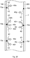
- the aircraft 1 comprises a set of electrical equipment 40a ... 40j in the part of the fuselage represented on the figure 5 .
- This electrical equipment each requires a power supply to operate.
- the first busbar 120 has connection points 24a ... 24h at different locations distributed along its length, in its portion shown in the figure.
- the second busbar 220 has connection points 24i ... 24p at different locations distributed along its length, in its portion shown in the figure.
- Each of the electrical equipment of the set of electrical equipment is connected to a connection point of a busbar of the set of busbars, via a local power supply connection 42.
- the 40a electrical equipment is connected to the connection point 24a of the first busbar 120.
- the equipment 40b, 40c and 40d are connected to the connection point 24d.
- the electrical equipment 40e and 40f are connected to the connection point 24g.
- the electrical equipment 40g is connected to the connection point 24i of the second busbar 220.
- the electrical equipment 40h and 40i are connected to the connection point 24l.
- the electrical equipment 40j is connected to the connection point 24o.
- the connection points 24a, 24d, 24g, 24i, 241 and 24o receiving local electrical supply links 42 of electrical equipment are equipped with junction boxes provided with sockets or connectors making it possible to easily connect these links. Local power supply 42.
- connection points not receiving a local power supply link are not equipped with such junction boxes to limit the mass of the aircraft.
- two consecutive connection points of a busbar are spaced apart by a distance of about 50 to 70 cm. This distance corresponds for example to the distance between two structural frames of the aircraft.
- the junction boxes can for example be installed every 4 or 5 connection points in a major part of the fuselage. However, in areas of the fuselage corresponding to a particularly high density of electrical equipment, all connection points, or sometimes every other connection point, may be equipped with junction boxes.
- the set of busbars forms an infrastructure of the electrical power distribution network 200 of the aircraft.
- the different electrical equipment 40a ... 40i are each connected to a connection point of a busbar via a local power supply connection 42. It is thus possible to easily add new electrical equipment to the fuselage without modify this infrastructure: it suffices to set up a local power supply connection between this new equipment and a connection point of a busbar. Preferably, this connection point is chosen as close as possible, on the considered busbar, of the new electrical equipment.
- This addition of new electrical equipment can be provided both during the manufacture of the aircraft, and during a modification of the configuration of the aircraft after delivery to an airline.
- the aircraft 1 further comprises a third generator G3 near the engine E1 and a fourth generator G4 near the engine E2.
- the set of busbars further comprises a third busbar 320, 320a and a fourth busbar 420, 420a.
- the third busbar and the fourth busbar each have a portion 320, respectively 420, extending in a longitudinal direction of the fuselage F.
- the four busbars take segregated paths in the fuselage, as shown in FIG. figure 3 . As indicated above, the part 120 of the first busbar travels in a left part of the fuselage and the part 220 of the second busbar travels in a right part of the fuselage.
- the part 320 of the third busbar travels in a left part of the fuselage and the part 420 of the fourth busbar travels in a right part of the fuselage.
- Part 120 of the first busbars and part 220 of the second busbars run in an upper part of the fuselage, while part 320 of the third busbars and part 420 of the fourth busbars run in a lower part of the busbars.
- the third busbar comprises a portion 320a in the left wing of the aircraft and the fourth busbar comprises a portion 420a in the right wing of the aircraft.
- the third busbar 320, 320a and the fourth busbar 420, 420a are also connected to the switching system 30.
- the switching system 30 is configured to Electrically connect the third G3 electrical generator to the third busbar and the fourth G4 electrical generator to the fourth busbar.
- the third electrical generator G3 is electrically connected to the switching system 30 via dedicated conductors (or bars) of the third busbar 320, 320a and the fourth electrical generator G4 is electrically connected to the switching system via dedicated conductors of the fourth busbar 420, 420a.
- the third generator G3 located in the left wing of the aircraft, close to the engine E1 is connected to dedicated conductors of the portion 320a of the third busbar, by a local power supply connection between this generator and this part 320a of the third busbar.
- the fourth generator G4 located in the right wing of the aircraft, close to the engine E2 is connected to dedicated conductors of the portion 420a of the fourth busbar, by a local power supply connection. between this generator and this part 420a of the fourth busbar.
- a busbar 20 of the set of busbars comprises a set of electrical conductors corresponding to bars 25a, 25b, 25c.
- bars 25a, 25b and 25c are shown in the figure, this number of bars should not be interpreted in a limiting manner of the invention.
- Those skilled in the art will be able to adapt the number of bars according to the different electrical voltages to be distributed to the electrical equipment of the aircraft by means of the electrical power distribution network 200 and according to the number of separate segregations required.
- These bars run parallel or substantially parallel along a length of the busbar 20. They are separated from each other by an electrically insulating material 22, for example a plastic or air.
- the set of bars is surrounded by an envelope 28.
- this envelope is formed of an electrically insulating material.
- the envelope 28 is formed of an electrically conductive material.
- An electrically insulating material 22 is then placed between the bars 25a, 25b and 25c on the one hand and the envelope 28 on the other hand.
- This other embodiment is advantageous because it makes it possible to use the envelope 28 as an electrical current return conductor (for example example AC neutral conductor, 0 volts DC voltage, etc.) and / or as electromagnetic shielding for avoiding electromagnetic disturbances of electrical equipment of the aircraft by electric currents flowing in the bars 25a, 25b, 25c.
- the busbar portion 20 shown in the figure comprises a connection point 24. This connection point comprises an opening 29 of the envelope 28, for example on an upper face (in the figure) of said envelope.
- the opening 29 thus delimits two parts 28a and 28b of the upper face of the casing 28.
- the part of the set of bars 25a, 25b, 25c facing the opening 29 is devoid of insulation 28 when this insulator corresponds to a plastic material, so as to allow the connection of a connection means on the bars 25a, 25b, 25c through the opening 29.
- a connecting means corresponds for example to a connector comprising blade assemblies. forming spring, which can be put in place on the bars.
- the switching system 30 includes a so-called reconfigured operating mode, which can be activated in the event of a failure in the electrical power distribution network.
- the switching system 30 is configured to establish electrical connections between on the one hand the electric generators G1, G2 (and possibly G3, G4 according to the embodiment) of the set of electric generators and secondly the busbars of the set of busbars, these electrical connections being modified with respect to electrical connections established in the normal operating mode.
- the switching system 30 is configured to establish electrical connections between busbars of the set of busbars. This second variant can be combined with the first variant.
- the switching system modifies the electrical connections so as to feed the first busbar 120, 120a, and the third busbar 320, 320a, from the generator G1.
- the switching system comprises a main switching device and at least one switching device. remote secondary switching of the main switching device.
- the main switching device is similar to the switching system 30 shown on the Figures 1, 2 and 3 and described previously. It provides, for example, an electrical core function of the aircraft.
- the at least one secondary switching device is controlled by the switching system 30 to which it is connected by a specific communication link or by a communication network of the aircraft.
- a secondary switching device 32a is offset at one end of the busbars of the set of busbars, for example in a rear part or in a front part of the fuselage F of the aircraft.
- the secondary switching device 32a comprises four switches K1, K2, K3, K4, corresponding for example to contactors that can be controlled by the switching system 30.
- these contactors comprise at least as many contacts as the busbars comprise electrical conductors 25a, 25b, 25c, etc.
- the contacts of the switches K1, K2, K3 and K4 are open, so that they do not establish any connection between the busbars 120, 220, 320 and 420.
- the figure 6b illustrates a situation in which a failure X has occurred on the first busbar 120. This failure has the effect of electrically isolating between them two parts 120x and 120y of the first busbar 120.
- the switching system controls the device. remote switching 32a, so as to close the contacts of the switch K1. This has the effect of connecting together similar conductors on the one hand part 120y of the first busbar and second part of the third busbar 320. This part 120y of the first busbar is then fed by the third generator G3 via switching system 30.
- At least one of the busbars of the set of busbars comprises at least two sections arranged end to end and electrically connected to each other. That is particularly interesting when the aircraft 1 is formed by assembling sections of the fuselage F. These fuselage sections are then pre-equipped with sections of busbars that are interconnected during or after the assembly of the fuselage sections.
- each of the parts 120, 220, 320 and 420 of the first, second, third and fourth busbars is composed of an assembly of busbar sections arranged end to end and electrically connected to each other.
- the busbar sections are specific to the fuselage sections in which they are integrated.
- each section of busbars integrated into a fuselage section consists of an assembly of modular busbar sections arranged end to end and electrically connected to each other.
- these modular busbar sections correspond to a limited number of lengths judiciously chosen so as to allow the pre-equipment of the different fuselage sections by combination of modular sections corresponding to these predefined lengths.
- a secondary switching device 32b is electrically connected to two consecutive sections (or two modular sections) of a busbar.
- a secondary switching device 32b is set up between two busbar sections 120j and 220j on the one hand and two busbar sections 120k and 220k on the other.
- the sections 120j and 120k correspond to two consecutive sections of the first busbar 120.
- the sections 220j and 220k correspond to two consecutive sections of the second busbar 220.
- the secondary switching device 32b comprises four switches K11, K12, K13, K14.
- these contactors comprise at least as many contacts as the busbars comprise electrical conductors 25a, 25b, 25c, and so on.
- the contacts of the switches K11 and K12 are closed so as to establish electrical connections between similar electrical conductors of the sections 120j and 120k of the first busbar on the one hand and 220j and 220k of the second busbar on the other hand.
- the contacts of the switches K13 and K14 are open, in such a way that they do not establish any connection between the first busbar and the second busbar.
- the figure 7b illustrates a situation in which a failure X has occurred on the section 120j first busbar 120.
- the switching system 30, although not shown in the figure, is considered to be left of the sections 120j and 220j in the figure.
- the failure X has the effect of interrupting the power supply of the busbar 120k by the generator G1via the switching system 30 and the busbar 120j.
- the switching system 30 controls the opening of the contacts of the switch K11 and the closing of the contacts of the switch K14. This has the effect of connecting together the similar contacts of the section 220j of the second busbar and the section 120k of the first busbar. This section 120k of the first busbar is then powered by the second generator G2 via the switching system 30 and the busbar 220j.
- the busbar section 20t and the set of data links 50t are mounted integral with each other.
- the busbar section 20t and the set of data links 50t are fixed on a common carrier 62.
- the data links of the set of data links 50t are attached. at the busbar section 20t.
- these data links correspond to plies of optical fibers
- these optical fiber plies are for example glued on one side of the busbar section 20t.
- the data links of the set of data links 50t correspond to twisted pairs of copper or aluminum wires.
- the data links correspond to optical fibers. In addition to a significant gain in mass, these optical fibers have the advantage of being insensitive to possible electromagnetic disturbances that could be produced when an electric current flows in bars of the busbar section 20t.
- the busbar section 20t has connection points 24 at different locations distributed along its length.
- the set of data links 50t has connection points 54 at different locations distributed along its length and each arranged near (or opposite) a connection point 24 of the busbar section 20t.
- the modular element 60 thus comprises pairs of connection points, each comprising on the one hand a connection point 24 of the busbar section 20t and on the other hand the connection point 54 of the set of data links. 50t, located near said connection point 24.
- the busbar section 20t includes a first interconnection point 27a and the set of data links 50t comprises a first interconnection point 57a. These first interconnection points 27a and 57a are located at a first longitudinal end Ext1 of the modular element 60.
- first interconnection points 27a and 57a are provided for connecting the busbar section 20t and the set of links. 50t respectively to a busbar section and to a set of data links of a first other modular element arranged longitudinally in series with the modular element 60.
- the busbar section 20t has a second point of contact.
- interconnection 27b and the set of data links 50t has a second interconnection point 57b.
- These second interconnection points 27b and 57b are located at a second longitudinal end Ext2 of the modular element 60.
- These second interconnection points 27b and 57b are provided for connecting the busbar section 20t and the set of links. 50t respectively to a busbar section and to a set of data links of a second other modular element arranged longitudinally in series with the modular element 60.
- the set of data links 50t also comprises at least one connection point, called the patch point, designed to receive a patch bay.
- this at least one stirring point is located at a longitudinal end of the modular element 60.
- the set of data links 50t comprises two mixing points 55a and 55b located respectively at the first longitudinal end Ext1 and at the second longitudinal end Ext2 of the modular element 60.
- the at least one patch point 55 is located between two connection points 54 of the set of data links 50t.
- the set of data links 50t also comprises at least one data link between, on the one hand, each of the connection points distributed along its length and, on the other hand, the patching point.
- These data links 56 are not represented on the Figures 8 and 9 for reasons of clarity of said figures.
- the set of data links 50t comprises at least one data link 56b1 between the patch point 55a and the connection point 54b and at least one data link 56b2 between the patch point 55b and the connection point 54b.
- each link shown in the figure may in fact correspond to a set of optical fibers, for example 8 optical fibers.
- the set of data links 50t also includes data links 58 between the first interconnection point 57a and the second interconnection point 57b. These links data 58 are particularly useful for establishing communications through several modular elements 60.
- At least one data link 56a, 56b, ... 56f is provided between the mixing point 55 and each connection point 54a, 54b ... 54f.
- at least one data link 58b is provided between the mixing point 55 and each interconnection point 57a, 57b.
- the brewing point (s) is (are) intended to receive a brewing bay.
- the modular element 60 comprises for example at least one fastener provided to allow the fixing of the brewing bay on the modular element.
- This attachment may in particular correspond to a nut or a screw, a mechanical part provided to cooperate with a part of the brewing chamber so as to clap it on the modular element, etc..
- the data links 56 arrive on one or more brewing connectors that can be integrated in the corresponding brewing rack.
- FIG. 12 An example of interconnection of two consecutive modular elements is illustrated by the figure 12 , in the case of modular elements 60i, 60i + 1 similar to the modular element 60 shown in FIG. figure 8 .
- the first end Ext1 of the modular element 60i + 1 is connected to the second end Ext2 of the modular element 60i.
- these two ends are arranged end to end, close to each other, so that the first interconnection point 27a of the busbar 20t of the modular element 60i + 1 faces the second interconnection point 27b of the busbar 20t of the modular element 60i and the first interconnection point 57a of the data link assembly 50t of the modular element 60i + 1 faces the second interconnection point 57b of the set of data links 50t of the modular element 60i.
- the similar conductors of the interconnection points 27a and 27b are electrically interconnected by means of electrical connections 66.
- the interconnection points 27a and 27b correspond to terminal blocks and the electrical connections 66 then correspond to cables of appropriate section.
- the interconnection points 27a and 27b correspond to connectors.
- the electrical connections 66 then correspond for example to a connection of said connectors. In particular, when they are connected, these connectors can slide longitudinally relative to each other so as to absorb longitudinal displacements of the two modular elements relative to one another, in particular during deformations. the aircraft in which the modular elements are installed.
- a patch bay 64 is installed to receive the interconnection points 57a of the modular element 60i + 1 and 57b of the modular element 60i, as well as the stirring points 55a of the modular element 60i + 1 and 55b of the modular element 60i.
- these points of interconnection and brewing are equipped with connectors which are then integrated in the brewing bay.
- the brewing bay makes it possible to set up the required interconnections, for example by means of jumpers. It also allows the integration of active elements such as switch or router type, when such equipment is necessary to achieve the interconnections. These active elements correspond, for example, to switches or routers of the Ethernet or USB type.
- the jumpers correspond to wired jumpers when the data links are of wired type (for example twisted pairs of copper or aluminum wires) or to optical jumper when the data links correspond to optical fibers.
- the brewing bay receiving the interconnection points 57a, 57b and the brewing points 55a, 55b, allows the introduction of jumpers to achieve different types of interconnections.
- a first type of interconnection corresponds to an interconnection of a first link between one of the patching points 55a, 55b and a connection point 24 of the data link assembly of one of the modular elements 60i, 60i + 1, with a second link between one of the patch points 55a, 55b and a connection point 24 of the data link assembly of one of the modular elements 60i, 60i + 1.
- a second type of interconnection corresponds to an interconnection of a first link between one of the patch points 55a, 55b and a connection point 24 of the data link assembly of one of the modular elements 60i, 60i + 1, with a second link arriving at one of the points of interconnection 57a, 57b.
- a third type of interconnection corresponds to an interconnection of a first link arriving at one of the points of interconnection 57a, 57b, with a second link arriving at the other of the points of interconnection 57a, 57b.
- the mixing rack is fixed on at least one of the modular elements 60i, 60i + 1 so as to cover the stirring points 55a, 55b and the interconnection points 57a, 57b, which enter the brewing bay by one or more cutouts thereof.
- the patching bay is fixed either on at least one of the modular elements 60i, 60i + 1, near its end Ext2, Ext1, or on the structure of the aircraft near the ends Ext2, Ext1 of the modular elements 60i, 60i + 1, without the patch bay covers these points of interconnection and brewing.
- the interconnection points 57a, 57b and the patch points 55a, 55b are then disposed at data link ends of the data link assemblies 50t sufficiently long and sufficiently flexible to allow the integration of said interconnection points and brewing in brewing bay 64.
- each of the different pairs of connection points 24, 54 of the modular element 60 is provided to receive a mixed junction box of electrical power distribution and data communication 68.
- a mixed junction box allows the connection of one or more local power distribution and / or data distribution links to one or more electrical equipment of the aircraft.
- the use of mixed junction boxes facilitates the connection of the electrical equipment to the modular elements 60: thus, it is not necessary to connect each electrical equipment to the busbar section 20t and to a data link of the entire system. 50t data links.
- the junction box 68 is for example provided with connectors facilitating the connection of local links to the electrical equipment.
- a pair of connection points is equipped with a junction box only if an electrical equipment is connected to this pair of connection points. This avoids an unnecessary increase in the mass of the aircraft.
- the busbar section 20t comprises at least one flexible part designed to allow deformations of the modular element 60 in response to deformations of the fuselage F of an aircraft when the modular element is installed in said fuselage of an aircraft.
- each electrically conductive member of the busbar portion 20t includes a spring over a portion of its length.
- the length L of a modular element 60 is between 3 and 10 meters, preferably between 6 and 10 meters.
- two consecutive pairs of connection points of the modular element are spaced apart by a distance of about 50 to 70 cm. This distance corresponds for example to the distance between two structural frames of the aircraft.
- the junction boxes 68 may for example be installed every 4 or 5 pairs of connection points in a major part of the fuselage. However, in areas of the fuselage corresponding to a particularly high density of electrical equipment, all couples of connection points, or sometimes a couple of connection points out of two, can be equipped with junction boxes.
- the invention also relates to an aircraft 1 comprising a fuselage F and a set of electrical equipment distributed in the fuselage.
- the aircraft comprises a mixed electrical power distribution and data communication network 600 comprising a set of modular elements 60a ... 60q similar to the aforementioned modular element 60.
- the mixed network 600 comprises a first mixed sub-network of electrical power distribution and data communication 160, 160a.
- This first mixed subnetwork is formed by assembling between them modular elements 60a ... 60h forming a first subset of the set of modular elements.
- the first mixed sub-network comprises a portion 160 which extends longitudinally in the fuselage F of the aircraft.
- it also comprises a portion 160a which extends in the left wing of the aircraft.
- the mixed network 600 also comprises a second mixed sub-network of electrical power distribution and data communication 260, 260a.
- This second mixed sub-network is formed by assembling between them modular elements 60i ... 60q forming a second subset of the assembly. modular elements.
- the second mixed sub-network comprises a portion 260 which extends longitudinally in the fuselage F of the aircraft.
- it also comprises a portion 260a which extends in the right wing of the aircraft.
- the first sub-network 160, 160a and the second sub-network 260, 260a take segregated paths in the fuselage F, for example in a left part of the fuselage for the first sub-network and in a right part of the fuselage for the second sub-frame.
- the aircraft 1 represented on the figure 15 comprises a fuselage F and a set of electric generators comprising a first generator G1 associated with an engine E1 of the aircraft and a second generator G2 associated with an engine E2 of the aircraft.
- the aircraft 1 also comprises a mixed electrical power distribution and data communication network 600.
- the mixed network 600 comprises a set of busbars, among which a first busbar and a second busbar.
- a set of data links is associated with each busbar in the set of busbars.
- Each set of data links extends substantially parallel to the busbar with which it is associated.
- the first busbar and the set of data links associated with this first busbar form a first mixed sub-network of electrical power distribution and data communication 160, 160a.
- the second busbar and the set of data links associated with this second busbar form a second mixed sub-network of electrical power distribution and data communication 260, 260a.
- Each of the two sub-networks comprises at least one part 160, respectively 260, extending in a longitudinal direction of the fuselage F.
- These two sub-networks take segregated paths in the fuselage F of the aircraft, respectively in a left part of the fuselage (or port) for the part 160 of the first sub-network and in a right part of the fuselage (or starboard) for the part 260 of the second sub-network. This makes it possible to avoid a common fault on the two sub-networks in the event of an incident in a part of the fuselage.
- the first sub-network comprises a portion 160a in a left wing of the aircraft and the second sub-network comprises a portion 260a in a right wing of the aircraft.
- the electrical power distribution network also comprises a switching system 30.
- This switching system is electrically connected to the first electric generator G1 and the second electric generator G2, as well as to the first busbar of the first subassembly. network 160, 160a and the second busbars of the second sub-network 260, 260a.
- the switching system 30 comprises a so-called normal operating mode, in which it is configured to electrically connect the first electrical generator G1 to the first busbar and the second electrical generator G2 to the second busbar.
- the aircraft 1 also comprises a set of electrical equipment distributed in the fuselage. For the sake of clarity of the figure, these electrical equipment are not represented on the figure 15 .
- each busbar 20 of the set of busbars has connection points 24 at different locations distributed along its length and each set of data links 50 has connection points 54 at different locations distributed along its length.
- the connection points 54 are each arranged near (or opposite) a connection point 24 of the busbar 20 with which the set of data links 50 is associated, so as to form couples of connection points comprising each a connection point 24 of the busbar and a connection point 54 of the associated data link set.
- two consecutive pairs of connection points are spaced apart by a distance of about 50 to 70 cm. This distance corresponds for example to the distance between two structural frames of the aircraft.
- the mixed power distribution and data communication network 600 has been described in the particular case where it comprises 2 sub-networks 160, 160a and 260, 260a, the third aspect of the invention is in no way limited to this number of sub networks.
- the mixed network 600 may comprise 4 sub-networks using segregated paths in the fuselage of the aircraft, in the same way that the electrical power distribution network 200 according to the first aspect of the invention may comprise 4 sets of bars taking segregated paths in the fuselage.
- At least one busbar 20 of the set of busbars comprises at least two modular sections arranged end to end and electrically connected to each other.
- This at least one busbar is part of one of the sub-networks 160, 160a or 260, 260a.
- Each of said at least two modular sections of the at least one busbar is part of a modular element also comprising a set of data links extending substantially parallel to the modular section considered.
- Such a modular element corresponds for example to the modular element 60 according to an embodiment of the second aspect of the invention.
- the sets of data links of consecutive modular elements are interconnected so as to form the set of data links 50 associated with the busbar 20 considered.
- the mixed electrical power distribution and data communication network 600 comprises a set of branch boxes, each branch box 70 being connected to a pair of connection points 24, 54 as shown in FIG. figure 17 .
- These junction boxes are provided to allow the connection of the electrical equipment of the aircraft to the connection points 24 of the busbar 20 and the connection points 54 of the set of data links 50.
- the number branch boxes 70 installed on power distribution subnetworks Electrical and data distribution is a function of the density of electrical equipment in the fuselage F of the aircraft.
- the junction boxes can be installed every 4 or 5 pairs of connection points 24, 54, as shown in the lower part of the figure 17 .
- the junction boxes can be installed every 2 pairs of connection points, or even on each pair of connection points, as shown in the upper part of the figure 17 .
- the set of data links 50 comprises at least one particular connection point, called the stirring point 55.
- This at least one stirring point 55 is designed to receive a mixing rack 64.
- the set of data links 50 comprises data links between the mixing point 55 and different connection points 54.
- the patching bay allows said data links to be interconnected by means of jumpers.
- Each of the electrical equipment of the set of electrical equipment is connected to a pair of connection points via a local power supply link 42 and / or via a local data link 43, as shown in FIG. figure 20 .
- the aircraft 1 comprises a set of electrical equipment 40a ... 40j in the fuselage portion F shown in the figure. These electrical equipments each require a power supply to operate, except the 40g equipment which is autonomous in energy. Electrical equipment, except 40d equipment, also each requires a data link.
- Each electrical equipment is connected to a single pair of connection points, by means of said local links 42 and / or 43, preferably via a junction box 70a ... 70f.
- the portion 160 of the first sub-array is equipped with 3 junction boxes 70a, 70b, 70c and the portion 260 of the second sub-array is equipped with 3 junction boxes 70d, 70e, 70f.
- the electrical equipment 40a is connected to the junction box 70a by a local power supply connection 42 and by a local data link 43.
- the electrical equipment 40b and 40c are connected to the junction box 70b by means of a connection. local power supply 42 and a local data link 43.
- the equipment 40d is connected to the junction box 70b only through a local power supply link 42.
- the electrical equipment 40e and 40f are connected to the junction box 70c by a local power supply link 42 and by a data link.
- the electrical equipment 40g is connected to the junction box 70d only by a local data link 43.
- the electrical equipment 40h and 40i are connected to the junction box 70e by a local power supply connection 42 and by a local data link 43.
- the electrical equipment 40j is connected to the junction box 70f by a local power supply connection 42 and by a local data link 43.
- the junction boxes 70a , 70b, 70c on the one hand and 70d, 70e, 70f on the other hand are installed every 4 or 5 pairs of connection points, respectively on the part 16 0 of the first subnet and 260 of the second subnet. When the pairs of connection points are spaced for example 50cm, two consecutive junction boxes are then spaced about 2 meters apart.
- a junction box 70 comprises a power supply connector 724, a data link connector 754 and a set of locations E1, E2, ... E6 provided to each receive an interface module.
- the power supply connector 724 is provided to cooperate with the point of connection 24 of the pair of connection points to which the junction box is connected.
- the data link connector 754 is provided to cooperate with the connection point 54 of the set of data links belonging to the pair of connection points to which the junction box is connected. This data link connector corresponds for example to at least one multi-fiber optical connector when the data links of the distribution network 600 correspond to optical fibers.
- the junction box 70 also comprises a set of electrical connections 72 extending between the power supply connector 724 and the different locations E1, E2,... E6 provided for receiving the interface modules, as well as a set of electrical connections 72. data links 75 extending between the data link connector 754 and the different slots for receiving the interface modules.
- the data links of the distribution network 600 correspond to optical fibers and the junction box 70 further comprises a data link converter 78.
- This converter is intended to convert optical fiber communications into wired communications and vice versa.
- the set of data links 75 then comprise optical fiber data links 75a between the data link connector 754 and the data link converter 78, as well as data links 75b using electrical signals between the data link converter 75a and the data link connector 75b.
- data links 78 and the different locations E1, E2, ... E6 provided to receive the interface modules.
- This variant has the advantage of allowing fiber optic communications over the set of data links of the mixed network 600 of electrical power distribution and data communication. These communications are thus insensitive to electromagnetic disturbances.
- junction box 70 which allows a wired connection of the data links 75b with the interface modules that can be installed in the locations E1, E2, ... E6 .
- a wired connection has a better reliability than an optical connection in that the interface modules are likely to be replaced or moved. Indeed, such a wired connection is less sensitive to dust and vibrations than an optical connection.
- the connectors 724 and 754 are disposed on a rear face of the junction box 70.
- the electrical connections 72 and the data links 75 are made by means of a backplane board of the junction box. . These links arrive on the connectors of the backplane board, arranged next to the locations E1, E2,... E6 so that the interface modules likely to be installed in said locations can be plugged into these connectors. .
- electrical equipment is connected to electrical interface modules Pa, Pb by local power supply links 42k ... 42q and / or to link interface modules of Da, Db data via local data links 43k ... 43q.
- the electrical interface modules Pa, Pb are respectively installed in the locations E2, E6 of the junction box 70 and the data link interface modules Da, Db are respectively installed in the locations E3, E5 of the junction box 70.
- electrical equipment which requires a power supply and a data link is connected to an electrical interface module by a local power supply connection and to a data link interface module by a local data link.
- the electrical equipment 40k is connected to the electrical interface module Pa by a local power supply link 42k and the data link interface module Da by a local data link 43k.
- the local power supply links 42k ... 42q and the local data links 43k ... 43q are terminated by connectors capable of cooperating with connectors of the interface modules.
- the rear face of the junction box 70 comprises supports designed to hold the connectors of the local power supply links and local data links in position, such that these connectors are connected to the corresponding connectors of the connectors. interface modules when the interface modules are installed in their respective locations in the junction box. This advantageously makes it possible to remove and set up the interface modules in the locations E1, E2,... E6 of the junction box without having to manipulate the connectors of the various data links. This also makes it possible to avoid connection errors of said links.
- the junction box includes a backplane board 73.
- the connectors 724 and 754 are integral with the backplane board. These connectors are arranged such that when the junction box is installed on a pair of connection points, as shown in the figure, the power supply connector 724 is connected to the connection point of the busbar 20 and the connector of data links 754 may receive a connector of a 54x end of data links from the connection point of the data link assembly 50.
- the interface module Da is shown inserted in a location of the junction box 70. This interface module is connected to the backplane board 73 by means of a power supply connector 72i is a data link connector 75i.
- the arrow F represents a direction of extraction (upward in the figure) and insertion (downward in the figure) of the interface module in the junction box 70.
- the local data links 43k and 43l to electrical equipment 40k and 40l are terminated by respective connectors Ck and Cl connected to the interface module.
- the rear face of the junction box 70 (shown below in the figure) comprises not shown supports provided for holding in position the connectors Ck and Cl.
- the junction box 70 may comprise a mixed interface module providing an electrical interface module function, as mentioned above, and a data link interface module function, as mentioned above.
- this mixed interface module may respond to congestion constraints of the locations of the junction box 70.
- electrical equipment 40r, 40s are each connected to a respective connector 79r, 79s of the junction box 70 by respective local links 423r, 423s. These local links are of mixed type power supply and data link.
- the connector 79r and the connector 79s of the junction box are each connected to an electrical interface module P and a data link interface module D, by internal connections to the junction box.
- the connector 79r is connected to the electrical interface module P by an electrical connection 412r and to the data link interface module D by a data link 413r.
- the connector 79s is connected to the electrical interface module P by an electrical connection 412s and to the data link interface module D by a data link 413s.
- the pinout of the various connectors 79r, 79s of the junction box is similar for all of said connectors.
- This makes it possible to use identical mixed local connections between the different electrical equipment and the connectors of the junction boxes to which these electrical equipment are connected. This results in a simplification of the connections of the electrical equipment by means of said mixed local links.
- this second particular embodiment is described with two electrical equipment and two interface modules, it is in no way limited to these numbers of electrical equipment and interface modules.
- the internal links 412r, 412s, 413r, 413s are terminated by connectors capable of cooperating with connectors of the interface modules P and D.
- rear face of the junction box 70 comprises supports provided for holding in position the connectors of said internal links, such that these connectors are connected to the corresponding connectors of the interface modules when the interface modules are installed in their respective locations of the junction box.
- modular elements 60i, 60i + 1 for an electrical power distribution network of an aircraft each comprise an envelope 28.
- Each modular element comprises a section of a busbar whose electrical conductors, not shown in FIG. are housed in the envelope 28.
- the busbar section extends along the length of the modular element considered.
- the busbar section of a modular element 60i, 60i + 1 comprises a first interconnection point 27a at a first longitudinal end and a second interconnection point 27b at a second longitudinal end.
- the first and second interconnection points 27a and 27b are provided for connecting the busbar section to a busbar section of another modular element arranged longitudinally in series with the modular element under consideration.
- the second interconnection point 27b of the modular element 60i is connected to the first interconnection point 27a of the modular element 60i + 1.
- the connection between the busbars of two consecutive modular elements corresponds to a connection making it possible to absorb longitudinal deformations of the aircraft.
- This connection is by example made by means of a connector provided to allow sliding of conductive elements participating in said connection.
- the envelope 28 corresponds to a structural part of the aircraft, in this case a part designed to support luggage compartments 96 in the cabin of the aircraft.
- This piece is for example a metal part or a piece of composite material whose thickness is chosen to support the mass of luggage boxes. When the piece is metal, aluminum, it comprises for example a 5mm thick face and other faces of thickness 2mm.
- the envelope 28 corresponding to each modular element 60i, 60i + 1 is fixed, by fastening means not shown in the figure, to a set of structural frames 94 of the aircraft.
- the envelopes 28 of the various modular elements support the luggage compartments 96 by means of fasteners 95.
- these fasteners 95 can be slidably mounted on the envelopes 28 of the modular elements so as to allow the luggage compartments to slide according to the length of the fuselage of the aircraft.
- the length of the envelope 28 corresponding to each modular element extends along two interframes of the fuselage of the aircraft.
- interframe designates the space between two consecutive structural frames of the fuselage.
- the length of the casing 28 could also extend in a single interlock or in a larger number of interlockings.
- the busbar section of a modular element has connection points 24 at different locations distributed along its length.
- An opening of the envelope 28 is provided next to each connection point 24 so as to allow the connection of at least one electrical equipment of the aircraft to the busbar section by means of a local electrical connection.
- the connection points are distributed on the busbar section corresponding to each modular element so as to have a connection point 24 for each interboard of the fuselage of the aircraft.
- Other arrangements are possible without departing from the scope of the invention, for example a connection point for two interframes of the fuselage.
- each modular element 60i, 60i + 1 are part of an electrical power distribution network of the aircraft, for example a network of electrical power distribution similar to networks 200 or 600 already described with reference to the first and second aspects of the invention.
- each modular element further comprises a set of data links, similar to the modular elements described with reference to the second aspect of the invention. Therefore, this advantageous embodiment is not further described, all the embodiments described with reference to the second aspect of the invention being equally applicable.
- the casing 28 of a busbar section of a modular element is part of a floor rail section 98 of an aircraft.
- the floor rail may correspond to a floor rail not provided for fixing seats or to a seat rail provided for fixing seats in the passenger cabin of the aircraft.
- only a part of the length of the floor rail section 98 is shown in the figure.
- each modular element is similar to the modular elements 60i, 60i + 1 described with reference to FIG. figure 23 .
- these modular elements can be arranged in series and interconnected by interconnection points 27a, 27b.
- Each modular element corresponding to a section of the floor rail of the aircraft, the series connection of floor rail sections in the fuselage cabin of the aircraft, to produce a floor rail, makes it possible to construct a distribution network electrical power of the aircraft.
- three conductive elements 25a, 25b, 25c of the busbar section are housed in the casing 28.
- the conductive elements are arranged horizontally inside the casing 28, so as to allow the realization of connection points 24 on a side face of the floor rail section 98.
- the horizontal term here means that the conductive elements are arranged horizontally when the floor rail section is installed on a floor of the fuselage cabin of the aircraft, the aircraft being parked on the ground.
- An opening 29 of the envelope 28 is provided opposite each connection point 24 so as to allow the connection of at least one electrical equipment from the aircraft to the busbar section by means of a local electrical connection.
- the floor rail is a seat rail
- the upper portion of the seat rail has a groove 97 for fixing seats.
- the electrical power distribution network 200 of an aircraft according to the first aspect of the invention can be achieved by assembling modular elements 60 according to the second aspect of the invention.
- the mixed power distribution and data communication network 600 according to the third aspect of the invention can be realized by assembling modular elements according to the second aspect of the invention.
- branch boxes 68 described in connection with the second aspect of the invention may be similar to branch boxes 70 described in more detail in connection with the third aspect of the invention.
Abstract
L'élément modulaire (60) pour un réseau mixte de distribution de puissance électrique et de communication de données (600) d'un aéronef comporte un tronçon d'un jeu de barres (20t) et un ensemble de liaisons de données (50t) s'étendant de façon sensiblement parallèle selon une longueur (L) de l'élément modulaire. Le tronçon de jeu de barres comporte des points de connexion (24) à différents emplacements répartis selon sa longueur. L'ensemble de liaisons de données comporte des points de connexion (54) à différents emplacements répartis selon sa longueur, disposés chacun à proximité d'un point de connexion (24) du tronçon de jeu de barres. Il comporte aussi une liaison de données (56) entre chacun des points de connexion (54) et un point de brassage (55, 55a, 55b). Le tronçon de jeu de barres (20t) et l'ensemble de liaisons de données (50t) comportent des points d'interconnexion (27a, 57a, 27b, 57b) permettant de relier l'élément modulaire à un premier et à un deuxième autres éléments modulaires disposés longitudinalement en série avec l'élément modulaire.

Description
La présente invention concerne le domaine de l'alimentation électrique d'équipements d'un aéronef. Les aéronefs, en particulier les aéronefs de transport, comportent des équipements électriques répartis notamment dans leur fuselage. Ces équipements électriques doivent être alimentés électriquement et, pour une partie d'entre eux, doivent être reliés à un réseau de communication de données. Pour cela, les aéronefs comportent des harnais de câbles de puissance électrique et de câbles de communication de données. Les harnais de câbles de puissance électrique s'étendent généralement entre un coeur électrique de l'aéronef (permettant notamment l'arrivée de puissance électrique depuis des sources de génération et/ou de conversion de puissance électrique) et les équipements électriques à alimenter. Les harnais de câbles de communication s'étendent généralement entre des équipements de communication de l'aéronef, par exemple un commutateur conforme au standard ARINC 664 part 7, et les équipements électriques reliés à ces équipements de communication.The present invention relates to the field of power supply equipment of an aircraft. Aircraft, in particular transport aircraft, comprise electrical equipment distributed in particular in their fuselage. These electrical equipment must be electrically powered and, for some of them, must be connected to a data communication network. For this, the aircraft comprise harnesses of electrical power cables and data communication cables. The electrical power cable harnesses generally extend between an electric core of the aircraft (notably allowing the arrival of electrical power from sources of generation and / or electric power conversion) and the electrical equipment to be powered. The communication cable harnesses generally extend between communications equipment of the aircraft, for example a switch compliant with the ARINC 664 part 7 standard, and the electrical equipment connected to these communications equipment.
Dans les aéronefs modernes, de plus en plus de fonctions sont mises en oeuvre de façon électrique. Ces fonctions nécessitent parfois des tensions électriques davantage variées que dans les anciennes générations d'aéronefs (par exemple 28VDC, 115VAC, 230VAC, 270VDC, 540VDC, etc.), ainsi que de nombreuses liaisons de communications de données entre différents équipements de l'aéronef. Il en résulte que les harnais sont plus complexes, plus volumineux et de masse plus élevée que dans les anciennes générations d'aéronefs. La mise en oeuvre des harnais est également plus complexe. Par conséquent, il serait souhaitable de simplifier la distribution d'énergie électrique et les liaisons de données des équipements électriques des aéronefs.In modern aircraft, more and more functions are implemented electrically. These functions sometimes require more varied electrical voltages than in older generations of aircraft (eg 28VDC, 115VAC, 230VAC, 270VDC, 540VDC, etc.), as well as many data communications links between different aircraft equipment. . As a result, harnesses are more complex, bulkier and of higher mass than in older generations of aircraft. The implementation of harnesses is also more complex. Therefore, it would be desirable to simplify the electrical power distribution and data links of aircraft electrical equipment.
Les différents harnais sont spécifiques à chaque type d'aéronef et sont également fonction d'une configuration de l'aéronef spécifique à la compagnie aérienne exploitant cet aéronef. Par exemple, selon que certains équipements électriques sont installés ou ne sont pas installés dans le fuselage, les harnais comportent ou ne comportent pas des câbles permettant l'alimentation électrique et des liaisons de données desdits équipements. Il en résulte que la liste des équipements électriques devant être installés dans un aéronef particulier doit être définie et figée suffisamment tôt avant la fabrication dudit aéronef de façon à pouvoir concevoir, fabriquer et installer à temps les harnais spécifiques à cet aéronef. Cette liste doit être définie d'autant plus tôt que les aéronefs sont généralement fabriqués par assemblage de tronçons de fuselage dans lesquels sont préinstallés des tronçons de harnais qui sont connectés entre eux après l'assemblage des tronçons de fuselage. Or, il serait souhaitable de pouvoir modifier la liste des équipements électriques devant être installés dans l'aéronef jusqu'à un stade plus avancé de fabrication dudit aéronef.The different harnesses are specific to each type of aircraft and also depend on a configuration of the aircraft specific to the airline operating this aircraft. For example, depending on whether certain electrical equipment is installed or not installed in the fuselage, the harnesses comprise or do not include cables for power supply and data links of said equipment. As a result, the list of electrical equipment to be installed in a particular aircraft must be defined and frozen sufficiently early before the manufacture of said aircraft so as to be able to design, manufacture and install in time the harnesses specific to this aircraft. This list must be defined even earlier than the aircraft are generally manufactured by assembly of fuselage sections in which are pre-installed sections of harnesses which are connected to each other after assembly of the fuselage sections. However, it would be desirable to be able to modify the list of electrical equipment to be installed in the aircraft to a more advanced stage of manufacture of said aircraft.
D'autre part, les harnais étant fabriqués de façon spécifique en fonction de la liste des équipements électriques installés dans l'aéronef, ainsi que des positions dans le fuselage desdits équipements, une modification de la configuration de l'aéronef après sa livraison à une compagnie aérienne est difficile. Or, une telle modification peut être nécessaire, par exemple lors d'une revente de l'aéronef à une autre compagnie aérienne ou si la compagnie aérienne souhaite ajouter de nouveaux équipements électriques dans l'aéronef. Par conséquent, il serait souhaitable de pouvoir modifier plus facilement la liste et les positions des équipements électriques d'un aéronef.On the other hand, the harnesses being specifically manufactured according to the list of electrical equipment installed in the aircraft, as well as positions in the fuselage of said equipment, a modification of the configuration of the aircraft after its delivery to an aircraft. airline is difficult. However, such a modification may be necessary, for example when the aircraft is sold to another airline or if the airline wishes to add new electrical equipment to the aircraft. Therefore, it would be desirable to be able to more easily modify the list and the positions of the electrical equipment of an aircraft.
La présente invention a notamment pour but d'apporter une solution, au moins partiellement, à ces problèmes.The present invention is intended in particular to provide a solution, at least partially, to these problems.
Selon un premier aspect de l'invention, l'invention concerne un aéronef comportant :
- un fuselage ;
- un ensemble de générateurs électriques, comprenant au moins un premier générateur électrique et un deuxième générateur électrique ;
- un ensemble d'équipements électriques, répartis dans le fuselage ; et
- un réseau de distribution de puissance électrique comportant :
- un ensemble de jeux de barres, comprenant au moins un premier jeu de barres et un deuxième jeu de barres ; et
- un système de commutation,
- chaque jeu de barres de l'ensemble de jeux de barres s'étend, au moins en partie, selon une direction longitudinale du fuselage ;
- le premier jeu de barres et le deuxième jeu de barres empruntent des chemins ségrégués dans le fuselage ;
- le système de commutation est relié électriquement au premier générateur électrique et au deuxième générateur électrique, ainsi qu'au premier jeu de barres et au deuxième jeu de barres ;
- le système de commutation comporte un mode de fonctionnement dit normal, dans lequel il est configuré pour relier électriquement le premier générateur électrique au premier jeu de barres et le deuxième générateur électrique au deuxième jeu de barres ;
- chaque jeu de barres de l'ensemble de jeux de barres comporte des points de connexion à différents emplacements répartis selon sa longueur ; et
- chacun des équipements électriques de l'ensemble d'équipements électriques est relié à un point de connexion d'un jeu de barres de l'ensemble de jeux de barres, via une liaison d'alimentation électrique locale.
- a fuselage;
- a set of electric generators, comprising at least a first electric generator and a second electric generator;
- a set of electrical equipment, distributed in the fuselage; and
- an electric power distribution network comprising:
- a set of busbars, comprising at least a first busbar and a second busbars; and
- a switching system,
- each busbar of the set of busbars extends, at least in part, in a longitudinal direction of the fuselage;
- the first busbars and the second busbars use segregated paths in the fuselage;
- the switching system is electrically connected to the first electrical generator and the second electrical generator, as well as to the first busbar and the second busbars;
- the switching system comprises a so-called normal operating mode, in which it is configured to electrically connect the first electrical generator to the first busbar and the second electrical generator to the second busbar;
- each busbar of the set of busbars has connection points at different locations distributed along its length; and
- each of the electrical equipment of the set of electrical equipment is connected to a connection point of a busbar of the set of busbars, via a local power supply connection.
L'ensemble de jeux de barres correspond à une infrastructure invariante du réseau de distribution de puissance électrique de l'aéronef. Les différents équipements électriques sont reliés chacun à un point de connexion d'un jeu de barres par une liaison d'alimentation électrique locale. Il est ainsi possible d'ajouter facilement un nouvel équipement électrique dans le fuselage, sans modifier cette infrastructure : il suffit pour cela de mettre en place une liaison d'alimentation électrique locale entre ce nouvel équipement et un point de connexion d'un jeu de barres. De préférence, ce point de connexion est choisi le plus proche possible, sur le jeu de barres considéré, du nouvel équipement électrique, afin notamment de faciliter la mise en place de la liaison d'alimentation électrique locale entre l'équipement électrique et le jeu de barres. Cet ajout d'un nouvel équipement électrique peut être prévu aussi bien pendant la fabrication de l'aéronef, que lors d'une modification de la configuration de l'aéronef après sa livraison à une compagnie aérienne. Il est également aisé de déplacer un équipement électrique dans le fuselage de l'aéronef, par exemple lors d'une modification de la configuration de l'aéronef : il suffit pour cela de retirer sa liaison d'alimentation électrique locale d'origine, d'amener l'équipement électrique à sa nouvelle position dans le fuselage et de mettre en place une nouvelle liaison d'alimentation électrique locale vers un autre point de connexion d'un jeu de barres. L'utilisation d'un ensemble de jeu de barres plutôt que de harnais de câbles permet également de réduire la masse ainsi que le coût du réseau de distribution de puissance électrique de l'aéronef. En effet, les conducteurs électriques d'un jeu de barres utilisés de façon commune par plusieurs équipements électriques nécessitent un dimensionnement moindre que la somme des dimensionnements de câbles distincts, dans des harnais, alimentant ces mêmes équipements électriques. Etant donné que le premier jeu de barres et le deuxième jeu de barres empruntent des chemins ségrégués dans le fuselage, dans le mode de fonctionnement normal ces deux jeux de barres sont complètement indépendants l'un de l'autre et ils ne risquent pas d'être exposés à une panne ou à un endommagement commun (par exemple en cas d'éclatement moteur...). Ainsi, l'alimentation électrique des équipements électriques reliés à un jeu de barres est totalement indépendante de l'autre jeu de barres. Par conséquent, en cas de panne affectant l'un des jeux de barres, seuls des équipements électriques reliés à des points de connexion de ce jeu de barres risquent d'être privés d'alimentation électrique. Les équipements électriques reliés à l'autre jeu de barres continuent alors d'être alimentés normalement puisque leur alimentation électrique est totalement indépendante du jeu de barres affecté par la panne.The set of busbars corresponds to an invariant infrastructure of the electrical power distribution network of the aircraft. The different electrical equipments are each connected to a connection point of a busbar by a local power supply connection. It is thus possible to easily add new electrical equipment in the fuselage, without modifying this infrastructure: it suffices to set up a local power supply connection between this new equipment and a connection point of a set of bars. Preferably, this connection point is chosen as close as possible, on the considered busbar, of the new electrical equipment, in particular to facilitate the establishment of the local power supply link between the electrical equipment and the game. of bars. This addition of new electrical equipment can be provided both during the manufacture of the aircraft, and during a modification of the configuration of the aircraft after delivery to an airline. It is also easy to move electrical equipment in the fuselage of the aircraft, for example during a modification of the configuration of the aircraft: it suffices for this purpose to remove its original local power supply link, d bring the electrical equipment to its new position in the fuselage and set up a new local power supply link to another connection point of a busbar. The use of a set of busbars rather than harnesses of cables also makes it possible to reduce the mass as well as the cost of the electrical power distribution network of the aircraft. Indeed, the electrical conductors of a busbar commonly used by several electrical equipment require sizing less than the sum of sizing separate cables in harnesses, supplying these same electrical equipment. Since the first busbars and the second busbars use segregated paths in the fuselage, in the normal operating mode these two busbars are completely independent of one another and they are not likely to be exposed to a common breakdown or damage (for example in the event of an engine burst ...). Thus, the power supply of the electrical equipment connected to a busbar is totally independent of the other busbars. Therefore, in the event of a fault affecting one of the busbars, only electrical equipment connected to the connection points of this busbar may be deprived of power supply. The electrical equipment connected to the other busbar then continues to be fed normally since their power supply is totally independent of the busbar affected by the breakdown.
Selon différents modes de réalisation pouvant être mis en oeuvre isolément ou combinés entre eux :
- le premier jeu de barres s'étend également en partie dans une première aile de l'aéronef et le deuxième jeu de barres s'étend également en partie dans une deuxième aile de l'aéronef ;
- le premier générateur électrique et le deuxième générateur électrique sont reliés électriquement au système de commutation via des jeux de barres. De façon avantageuse, le premier générateur électrique est relié électriquement au système de commutation via des conducteurs dédiés du premier jeu de barres et le deuxième générateur électrique est relié électriquement au système de commutation via des conducteurs dédiés du deuxième jeu de barres ;
- le réseau de distribution de puissance électrique comporte en outre un troisième jeu de barres et un quatrième jeu de barres qui s'étendent, au moins en partie, selon une direction longitudinale du fuselage, les premier, deuxième, troisième et quatrième jeux de barres empruntant des chemins ségrégués dans le fuselage de l'aéronef. De façon avantageuse, l'ensemble de générateurs électriques comprend en outre un troisième générateur électrique et un quatrième générateur électrique et, dans le mode de fonctionnement normal, le système de commutation est configuré pour relier électriquement le troisième générateur électrique au troisième jeu de barres et le quatrième générateur électrique au quatrième jeu de barres ;
- le système de commutation comporte un mode de fonctionnement dit reconfiguré, susceptible d'être activé en cas de survenance d'une panne dans le réseau de distribution de puissance électrique, dans lequel il est configuré pour :
- établir des liaisons électriques entre les générateurs électriques de l'ensemble de générateurs électriques et les jeux de barres de l'ensemble de jeux de barres, ces liaisons électriques étant modifiées par rapport à des liaisons électriques établies dans le mode de fonctionnement normal ; et/ou
- établir des liaisons électriques entre des jeux de barres de l'ensemble de jeux de barres ;
- le système de commutation comprend un dispositif de commutation principal et au moins un dispositif de commutation secondaire déporté du dispositif de commutation principal. De façon avantageuse, dans le mode de fonctionnement reconfiguré du système de commutation, l'au moins un dispositif de commutation secondaire est susceptible d'être commandé pour établir une ou plusieurs liaisons électriques entre des jeux de barres de l'ensemble de jeux de barres ;
- au moins un des jeux de barres de l'ensemble de jeux de barres comprend au moins deux tronçons modulaires disposés bout à bout et reliés électriquement entre eux. De façon avantageuse, un dispositif de commutation secondaire est relié électriquement à deux tronçons modulaires consécutifs d'un jeu de barres, de façon à établir des liaisons électriques entre des conducteurs électriques similaires des deux tronçons modulaires dans le mode de fonctionnement normal et à établir des liaisons électriques entre d'une part des conducteurs électriques d'au moins un des deux tronçons modulaires et d'autre part des conducteurs électriques d'un autre jeu de barres, dans le mode de fonctionnement reconfiguré.
- the first busbar also extends in part in a first wing of the aircraft and the second busbar also extends in part in a second wing of the aircraft;
- the first electrical generator and the second electrical generator are electrically connected to the switching system via busbars. Advantageously, the first electrical generator is electrically connected to the switching system via dedicated conductors of the first busbar and the second electrical generator is electrically connected to the switching system via dedicated conductors of the second busbar;
- the electrical power distribution network further comprises a third busbar and a fourth busbar which extend, at least in part, in a longitudinal direction of the fuselage, the first, second, third and fourth busbars passing through segregated paths in the fuselage of the aircraft. Advantageously, the set of electric generators further comprises a third electrical generator and a fourth electrical generator and, in the normal operating mode, the switching system is configured to electrically connect the third electrical generator to the third busbar and the fourth electric generator at the fourth busbar;
- the switching system comprises a so-called reconfigured operating mode, which can be activated in the event of a failure in the electrical power distribution network, in which it is configured to:
- establishing electrical connections between the electrical generators of the set of electric generators and the busbars of the set of busbars, these electrical connections being modified with respect to electrical connections established in the normal operating mode; and or
- establish electrical connections between busbars of the busbar assembly;
- the switching system comprises a main switching device and at least one remote secondary switching device of the main switching device. Advantageously, in the reconfigured operating mode of the switching system, the at least one secondary switching device can be controlled to establish one or more electrical connections between busbars of the set of busbars. ;
- at least one of the busbars of the set of busbars comprises at least two modular sections arranged end to end and electrically connected to each other. Advantageously, a secondary switching device is electrically connected to two consecutive modular sections of a busbar, so as to establish electrical connections between similar electrical conductors of the two modular sections in the normal operating mode and to establish electrical connections between, on the one hand, electrical conductors of at least one of the two modular sections and, on the other hand, electrical conductors of another busbar, in the reconfigured operating mode.
Selon un deuxième aspect de l'invention, l'invention concerne un élément modulaire pour un réseau mixte de distribution de puissance électrique et de communication de données d'un aéronef. Cet élément modulaire est remarquable en ce qu'il comporte :
- un tronçon d'un jeu de barres de distribution de puissance électrique, s'étendant selon une longueur de l'élément modulaire ; et
- un ensemble de liaisons de données, cet ensemble de liaisons de données s'étendant selon ladite longueur de l'élément modulaire, de façon sensiblement parallèle au tronçon de jeu de barres,
- le tronçon de jeu de barres comporte des points de connexion à différents emplacements répartis selon sa longueur ;
- l'ensemble de liaisons de données comporte des points de connexion à différents emplacements répartis selon sa longueur et disposés chacun à proximité d'un point de connexion du tronçon de jeu de barres ;
- l'ensemble de liaisons de données comporte un point de connexion, dit point de brassage, prévu pour recevoir une baie de brassage ;
- l'ensemble de liaisons de données comporte au moins une liaison de données entre d'une part chacun des points de connexion répartis selon sa longueur et d'autre part le point de brassage ;
- le tronçon de jeu de barres et l'ensemble de liaisons de données comportent chacun un premier point d'interconnexion prévu pour relier le tronçon de jeu de barres et l'ensemble de liaisons de données respectivement à un tronçon de jeu de barres et à un ensemble de liaisons de données d'un premier autre élément modulaire disposé longitudinalement en série avec l'élément modulaire, à une première extrémité longitudinale de l'élément modulaire ; et
- le tronçon de jeu de barres et l'ensemble de liaisons de données comportent chacun un deuxième point d'interconnexion prévu pour relier le tronçon de jeu de barres et l'ensemble de liaisons de données respectivement à un tronçon de jeu de barres et à un ensemble de liaisons de données d'un deuxième autre élément modulaire disposé longitudinalement en série avec l'élément modulaire, à une deuxième extrémité longitudinale de l'élément modulaire opposée à la première extrémité longitudinale.
- a section of an electric power distribution busbar extending along a length of the modular element; and
- a set of data links, this set of data links extending along said length of the modular element, substantially parallel to the busbar section,
- the busbar section has connection points at different locations distributed along its length;
- the set of data links has connection points at different locations distributed along its length and each arranged near a connection point of the busbar section;
- the set of data links comprises a connection point, called a patch point, designed to receive a patch bay;
- the set of data links comprises at least one data link between, on the one hand, each of the connection points distributed along its length and, on the other hand, the patching point;
- the busbar section and the set of data links each comprise a first interconnection point provided for connecting the busbar section and the set of data links respectively to a busbar section and to a busbar section. set of data links of a first other modular element disposed longitudinally in series with the modular element at a first longitudinal end of the modular element; and
- the busbar section and the set of data links each comprise a second interconnection point provided for connecting the busbar section and the set of data links respectively to a busbar section and to a busbar section. set of links data of a second other modular element disposed longitudinally in series with the modular element, at a second longitudinal end of the modular element opposite the first longitudinal end.
L'assemblage d'éléments modulaires conformes à l'invention permet de construire un réseau mixte de distribution de puissance électrique et de communication de données d'un aéronef. En ce qui concerne la distribution de puissance électrique, ce réseau présente les mêmes avantages que ceux décrits en référence au premier aspect de l'invention. Ce réseau présente également des avantages similaires en ce qui concerne la communication de données. L'utilisation d'éléments modulaires conformes à l'invention pour construire le réseau permet d'adapter facilement ce réseau à n'importe quel type d'aéronef, sans nécessiter de jeux de barres ou d'ensembles de liaisons de données spécifiques à l'aéronef considéré, en particulier en ce qui concerne leur longueur. L'utilisation d'un ou de quelques types d'éléments modulaires de longueurs prédéterminées permet d'adapter un tel réseau à tout aéronef, et aussi de mutualiser et de minimiser les coûts de développement.The assembly of modular elements according to the invention makes it possible to construct a mixed power distribution and data communication network of an aircraft. As regards the distribution of electrical power, this network has the same advantages as those described with reference to the first aspect of the invention. This network also has similar advantages in terms of data communication. The use of modular elements according to the invention to build the network makes it easy to adapt this network to any type of aircraft, without the need for busbars or sets of data links specific to the network. aircraft, particularly as regards their length. The use of one or a few types of modular elements of predetermined lengths makes it possible to adapt such a network to any aircraft, and also to pool and minimize development costs.
Selon différents modes de réalisation pouvant être mis en oeuvre isolément ou combinés entre eux :
- les liaisons de données correspondent à des fibres optiques ;
- le point de brassage comporte un sous-ensemble de liaisons de données terminées par au moins un connecteur, dit connecteur de brassage, prévu pour être intégré dans la baie de brassage. De façon avantageuse, le point de brassage comporte en outre au moins une fixation prévue pour permettre la fixation de la baie de brassage sur l'élément modulaire. De façon avantageuse encore :
- le point de brassage d'une part et le premier point d'interconnexion de l'ensemble de liaisons de données d'autre part sont situés à proximité de la première extrémité longitudinale de l'élément modulaire ;
- le premier point d'interconnexion de l'ensemble de liaisons de données comporte un sous-ensemble de liaisons de données terminées par au moins un connecteur, dit premier connecteur d'interconnexion ; et
- l'agencement du point de brassage et du premier point d'interconnexion est prévu pour permettre l'intégration du connecteur de brassage et du premier connecteur d'interconnexion dans la baie de brassage, de façon à permettre de relier l'ensemble de liaisons de données à l'ensemble de liaisons de données du premier autre élément modulaire, dans la baie de brassage ;
- l'élément modulaire est tel que :
- les points de connexion répartis le long du tronçon de jeu de barres et les points de connexion répartis le long de l'ensemble de liaisons de données, disposés chacun à proximité d'un point de connexion du tronçon de jeu de barres, forment des couples de points de connexion répartis le long de l'élément modulaire ; et
- chaque couple de points de connexion est prévu pour recevoir une boîte de dérivation mixte de distribution de puissance électrique et de communication de données configurée pour permettre le raccordement d'une ou de plusieurs liaisons locales de distribution d'alimentation électrique et/ou de distribution de données vers un ou plusieurs équipements électriques de l'aéronef ;
- le tronçon de jeu de barres comporte au moins une partie flexible prévue pour permettre des déformations de l'élément modulaire en réponse à des déformations d'un fuselage d'un aéronef lorsque l'élément modulaire est installé dans ledit fuselage d'un aéronef.
- the data links correspond to optical fibers;
- the patching point comprises a subset of data links terminated by at least one connector, said patching connector, intended to be integrated in the patch bay. Advantageously, the stirring point further comprises at least one attachment provided to allow the attachment of the mixing bay on the modular element. Advantageously again:
- the mixing point on the one hand and the first interconnection point of the set of data links on the other hand are located near the first longitudinal end of the modular element;
- the first interconnection point of the data link set comprises a subset of data links terminated by at least one connector, said first interconnect connector; and
- the mixing point and the first point of interconnection arrangement are provided to allow integration of the patching connector and the first interconnection connector into the patch bay, so as to connect the link assembly of data to the data link set of the first other modular element in the patch bay;
- the modular element is such that:
- the connection points distributed along the busbar section and the connection points distributed along the set of data links, each arranged near a connection point of the busbar section, form pairs connection points distributed along the modular element; and
- each pair of connection points is provided to receive a mixed electrical power distribution and data communication junction box configured to allow the connection of one or more local power distribution and / or power distribution links. data to one or more electrical equipment of the aircraft;
- the busbar section comprises at least one flexible part provided to allow deformation of the modular element in response to deformations of a fuselage of an aircraft when the modular element is installed in said fuselage of an aircraft.
L'invention est également relative à un aéronef comportant un fuselage et un ensemble d'équipements électriques répartis dans le fuselage. Cet aéronef est remarquable en ce que :
- l'aéronef comporte un réseau mixte de distribution de puissance électrique et de communication de données comprenant un ensemble d'éléments modulaires tels que précités ; et
- chacun des équipements électriques de l'ensemble d'équipements électriques est relié à un point de connexion du tronçon de jeu de barres d'un élément modulaire via une liaison d'alimentation électrique locale et/ou à un point de connexion de l'ensemble de liaisons de données dudit élément modulaire par une liaison de données locale.
- the aircraft comprises a mixed network of electrical power distribution and data communication comprising a set of modular elements as mentioned above; and
- each of the electrical equipment of the set of electrical equipment is connected to a connection point of the busbar section of a modular element via a local power supply connection and / or a connection point of the assembly data links of said modular element by a local data link.
Dans un mode particulier de réalisation :
- des éléments modulaires d'un premier sous-ensemble de l'ensemble d'éléments modulaires sont assemblés entre eux de façon à former un premier sous-réseau mixte de distribution de puissance électrique et de communication de données s'étendant, au moins en partie, longitudinalement dans le fuselage de l'aéronef ;
- des éléments modulaires d'un deuxième sous-ensemble de l'ensemble d'éléments modulaires sont assemblés entre eux de façon à former un deuxième sous-réseau mixte de distribution de puissance électrique et de communication de données s'étendant, au moins en partie, longitudinalement dans le fuselage de l'aéronef ; et
- le premier sous-réseau et le deuxième sous-réseau empruntent des chemins ségrégués dans le fuselage.
- modular elements of a first subset of the set of modular elements are assembled together to form a first mixed sub-network of electrical power distribution and data communication extending, at least in part longitudinally in the fuselage of the aircraft;
- modular elements of a second subset of the set of modular elements are assembled together to form a second mixed power distribution and data communication subnetwork extending, at least in part longitudinally in the fuselage of the aircraft; and
- the first subnet and the second subnet use segregated paths in the fuselage.
Dans un autre mode particulier de réalisation pouvant être combiné avec le précédent, deux éléments modulaires consécutifs sont reliés entre eux électriquement au moyen :
- d'au moins une connexion flexible ; ou
- d'au moins un élément de connexion configuré pour coulisser sur le tronçon d'un jeu de barres d'au moins l'un des deux éléments modulaires.
- at least one flexible connection; or
- at least one connecting element configured to slide on the section of a busbar of at least one of the two modular elements.
Dans encore un mode particulier de réalisation pouvant être combiné avec les précédents, la baie de brassage d'un élément modulaire reçoit :
- un connecteur d'interconnexion du premier autre élément modulaire ; et
- un ensemble de liaisons entre le premier connecteur d'interconnexion de l'élément modulaire et le connecteur d'interconnexion du premier autre élément modulaire.
- an interconnection connector of the first other modular element; and
- a set of links between the first interconnect connector of the modular element and the interconnect connector of the first other modular element.
Selon un troisième aspect de l'invention, l'invention concerne un aéronef comportant :
- un fuselage ;
- un ensemble d'équipements électriques, répartis dans le fuselage ; et
- un réseau mixte de distribution de puissance électrique et de communication de données.
- a fuselage;
- a set of electrical equipment, distributed in the fuselage; and
- a mixed network of electrical power distribution and data communication.
Cet aéronef est remarquable en ce que :
- le réseau mixte de distribution de puissance électrique et de communication de données comporte :
- un ensemble de jeux de barres, comprenant au moins un jeu de barres de distribution de puissance électrique ; et
- au moins un ensemble de liaisons de données,
- le réseau mixte de distribution de puissance électrique et de communication de données est configuré de telle façon qu'un ensemble de liaisons de données est associé à chaque jeu de barres de l'ensemble de jeux de barres ;
- chaque jeu de barres de l'ensemble de jeux de barres s'étend, au moins en partie, selon une direction longitudinale du fuselage ;
- chaque ensemble de liaisons de données s'étend de façon sensiblement parallèle au jeu de barres auquel il est associé ;
- chaque jeu de barres de l'ensemble de jeux de barres comporte des points de connexion à différents emplacements répartis selon sa longueur ; et
- chaque ensemble de liaisons de données comporte des points de connexion à différents emplacements répartis selon sa longueur et disposés chacun à proximité d'un point de connexion du jeu de barres auquel est associé l'ensemble de liaisons de données, de façon à former des couples de points de connexion comprenant chacun un point de connexion du jeu de barres et un point de connexion de l'ensemble de liaisons de données associé ; et
- chacun des équipements électriques de l'ensemble d'équipements électriques est relié à un couple de points de connexion via une liaison d'alimentation électrique locale et/ou via une liaison de données locale.
- the mixed power distribution and data communication network comprises:
- a set of busbars, comprising at least one power distribution busbar; and
- at least one set of data links,
- the mixed power distribution and data communication network is configured such that a set of data links is associated with each busbar of the set of busbars;
- each busbar of the set of busbars extends, at least in part, in a longitudinal direction of the fuselage;
- each set of data links extends substantially parallel to the busbar with which it is associated;
- each busbar of the set of busbars has connection points at different locations distributed along its length; and
- each set of data links has connection points at different locations distributed along its length and each arranged near a connection point of the busbar with which the set of data links is associated, so as to form pairs connection points each comprising a busbar connection point and a connection point of the associated data link set; and
- each of the electrical equipment of the set of electrical equipment is connected to a pair of connection points via a local power supply link and / or via a local data link.
Comme pour le premier aspect de l'invention, l'ensemble de jeux de barres correspond à une infrastructure invariante du réseau de distribution de puissance électrique de l'aéronef. Il présente les mêmes avantages que ceux décrits en référence au premier aspect de l'invention. L'au moins un ensemble de liaisons de données correspond à infrastructure invariante du réseau de communication de données. Les équipements électriques qui nécessitent une liaison de communication de données sont reliés chacun à un point de connexion de l'ensemble de liaisons de données par une liaison de données locale. Cela présente des avantages similaires à ceux du réseau de distribution de puissance électrique en ce qui concerne l'ajout ou le déplacement d'équipements électriques. Lorsqu'un équipement nécessite à la fois une alimentation électrique et une liaison de données, le fait que chaque point de connexion de l'ensemble de liaisons de données soit situé à proximité d'un point de connexion du jeu de barres auquel est associé l'ensemble de liaisons de données, permet de faciliter le raccordement de l'équipement à l'infrastructure du réseau de distribution de puissance électrique et à l'infrastructure du réseau de communication de données : la liaison d'alimentation électrique locale et la liaison de données locale peuvent ainsi cheminer ensemble entre l'équipement électrique et lesdits points de connexion.As for the first aspect of the invention, the set of busbars corresponds to an invariant infrastructure of the electrical power distribution network of the aircraft. It has the same advantages as those described with reference to the first aspect of the invention. The at least one set of data links corresponds to the invariant infrastructure of the data communication network. Electrical equipment that requires a data communication link is each connected to a connection point of the set of data links by a local data link. This has advantages similar to those of the electric power distribution network with respect to adding or moving electrical equipment. When equipment requires both a power supply and a data link, the fact that each connection point of the set of data links is located near a connection point of the busbar with which the set of data links is associated , facilitates the connection of the equipment to the power distribution network infrastructure and the data communication network infrastructure: the local power supply link and the local data link can thus travel together between the electrical equipment and said connection points.
Dans un mode de réalisation, le réseau mixte de distribution de puissance électrique et de communication de données comporte un ensemble de boîtes de dérivation, chaque boîte de dérivation étant raccordée à un couple de points de connexion. De façon avantageuse, une boîte de dérivation de l'ensemble de boîtes de dérivation comporte :
- au moins un connecteur d'alimentation électrique configuré pour coopérer avec le point de connexion du jeu de barres appartenant au couple de points de connexion auquel est raccordée la boîte de dérivation ;
- au moins un connecteur de liaisons de données configuré pour coopérer avec le point de connexion de l'ensemble de liaisons de données appartenant au couple de points de connexion auquel est raccordée la boîte de dérivation ; et
- un ensemble d'emplacements prévus pour recevoir des modules d'interface ;
- un ensemble de liaisons électriques s'étendant entre le connecteur d'alimentation électrique et les différents emplacements prévus pour recevoir les modules d'interface ; et
- un ensemble de liaisons de données s'étendant entre le connecteur de liaisons de données et les différents emplacements prévus pour recevoir les modules d'interface.
- au moins un module d'interface électrique dans un emplacement de la boîte de dérivation et/ou au moins un module d'interface de liaison de données dans un emplacement de la boîte de dérivation ; et
- au moins une liaison d'alimentation électrique locale entre ledit au moins un module d'interface électrique et un équipement électrique de l'aéronef et/ou au moins une liaison de données locale entre ledit au moins un module d'interface de liaison de données et un équipement électrique de l'aéronef.
- at least one power supply connector configured to cooperate with the connection point of the busbar belonging to the pair of connection points to which the junction box is connected;
- at least one data link connector configured to cooperate with the connection point of the set of data links belonging to the pair of connection points to which the junction box is connected; and
- a set of slots for receiving interface modules;
- a set of electrical links extending between the power supply connector and the different slots for receiving the interface modules; and
- a set of data links extending between the data link connector and the different slots for receiving the interface modules.
- at least one electrical interface module in a junction box location and / or at least one data link interface module in a junction box location; and
- at least one local power supply link between said at least one electrical interface module and an electrical equipment of the aircraft and / or at least one local data link between said at least one data link interface module and electrical equipment of the aircraft.
Le module d'interface électrique est par exemple choisi parmi l'ensemble suivant :
- un module de connexion électrique ;
- un module de commutation électrique ;
- un module de conversion de tension électrique ; et
- un module de protection électrique.
- an electrical connection module;
- an electrical switching module;
- an electric voltage conversion module; and
- an electrical protection module.
Le module d'interface de liaison de données est par exemple choisi parmi l'ensemble suivant :
- un module de connexion de liaisons de données ;
- un module de conversion de liaisons de données ;
- un module de liaison de données sans fil ; et
- un module d'acquisition et de concentration de données.
- a data link connection module;
- a data link conversion module;
- a wireless data link module; and
- a module for acquiring and concentrating data.
De façon avantageuse, l'aéronef comporte, dans un emplacement de la boîte de dérivation, un module d'interface mixte assurant une fonction de module d'interface électrique et une fonction de module d'interface de liaison de données.Advantageously, the aircraft comprises, in a location of the junction box, a mixed interface module providing an electrical interface module function and a data link interface module function.
De façon avantageuse encore, l'aéronef est tel que :
- les liaisons de données de l'ensemble de liaisons de données associé au jeu de barres correspondent à des fibres optiques ;
- l'ensemble de liaisons de données s'étendant entre le connecteur de liaisons de données et les différents emplacements prévus pour recevoir les modules d'interface comprend :
- un convertisseur de liaisons de données ;
- des liaisons de données par fibres optiques, entre le connecteur de liaisons de données et le convertisseur de liaisons de données ;
- des liaisons de données utilisant des signaux électriques, entre le convertisseur de liaisons de données et les différents emplacements prévus pour recevoir les modules d'interface.
- the data links of the set of data links associated with the busbar correspond to optical fibers;
- the set of data links extending between the data link connector and the different locations provided for receiving the interface modules comprises:
- a data link converter;
- fiber optic data links between the data link connector and the data link converter;
- data links using electrical signals between the data link converter and the different locations for receiving the interface modules.
Dans un mode particulier de réalisation pouvant être combiné avec les précédents :
- au moins un jeu de barres de l'ensemble de jeux de barres comprend au moins deux tronçons modulaires disposés bout à bout et reliés électriquement entre eux ;
- chacun des au moins deux tronçons modulaires de l'au moins un jeu de barres fait partie d'un élément modulaire comprenant également un ensemble de liaisons de données s'étendant de façon sensiblement parallèle au tronçon modulaire considéré ; et
- les ensembles de liaisons de données d'éléments modulaires consécutifs sont reliés entre eux de façon à former l'ensemble de liaisons de données associé au jeu de barres considéré.
- at least one busbar of the set of busbars comprises at least two modular sections arranged end to end and electrically connected to each other;
- each of the at least two modular sections of the at least one busbar is part of a modular element also comprising a set of data links extending substantially parallel to the modular section considered; and
- the sets of data links of consecutive modular elements are interconnected so as to form the set of data links associated with the busbar considered.
Selon un quatrième aspect de l'invention, l'invention concerne un élément modulaire pour un réseau de distribution de puissance électrique d'un aéronef.According to a fourth aspect of the invention, the invention relates to a modular element for an electrical power distribution network of an aircraft.
Cet élément modulaire est remarquable en ce qu'il comporte un tronçon d'un jeu de barres de distribution de puissance électrique, s'étendant selon une longueur de l'élément modulaire, et en ce que :
- le tronçon de jeu de barres comporte des points de connexion à différents emplacements répartis selon sa longueur ;
- le tronçon de jeu de barres comporte un premier point d'interconnexion prévu pour relier le tronçon de jeu de barres à un tronçon de jeu de barres d'un premier autre élément modulaire disposé longitudinalement en série avec l'élément modulaire, à une première extrémité longitudinale de l'élément modulaire ;
- le tronçon de jeu de barres comporte un deuxième point d'interconnexion prévu pour relier le tronçon de jeu de barres à un tronçon de jeu de barres d'un deuxième autre élément modulaire disposé longitudinalement en série avec l'élément modulaire, à une deuxième extrémité longitudinale de l'élément modulaire opposée à la première extrémité longitudinale ;
- le tronçon de jeu de barres comprenant un ensemble de conducteurs électriques, ces conducteurs électriques du tronçon de jeu de barres sont logés dans une enveloppe correspondant à une pièce structurelle de l'aéronef ; et
- ladite enveloppe comporte des ouvertures en regard des points de connexion du tronçon de jeu de barres, de façon à permettre le raccordement d'au moins un équipement électrique de l'aéronef au tronçon de jeu de barres au moyen d'une liaison électrique locale.
- the busbar section has connection points at different locations distributed along its length;
- the busbar section comprises a first interconnection point provided for connecting the busbar section to a busbar section of a first other modular element arranged longitudinally in series with the modular element at a first end; longitudinal of the modular element;
- the busbar section comprises a second interconnection point provided for connecting the busbar section to a busbar section of a second other modular element arranged longitudinally in series with the modular element, at a second end longitudinal of the modular element opposite the first longitudinal end;
- the busbar section comprising a set of electrical conductors, these electrical conductors of the busbar section are housed in an envelope corresponding to a structural part of the aircraft; and
- said envelope has openings facing the connection points of the busbar section, so as to allow the connecting at least one electrical equipment of the aircraft to the busbar section by means of a local electrical connection.
L'assemblage d'éléments modulaires conformes à l'invention permet de construire un réseau de distribution de puissance électrique d'un aéronef. En ce qui concerne la distribution de puissance électrique, ce réseau présente les mêmes avantages que ceux décrits en référence au premier et au deuxième aspects de l'invention. Les éléments modulaires conformes à l'invention comportant une enveloppe correspondant à une pièce structurelle de l'aéronef, c'est-à-dire une pièce participant à la structure mécanique de l'aéronef, il en résulte un gain de masse de l'aéronef. En effet, ces éléments modulaires ne nécessitent pas une enveloppe spécifique pour protéger et isoler leurs conducteurs électriques.The assembly of modular elements according to the invention makes it possible to construct an electrical power distribution network of an aircraft. As regards the distribution of electrical power, this network has the same advantages as those described with reference to the first and second aspects of the invention. The modular elements according to the invention comprising an envelope corresponding to a structural part of the aircraft, that is to say a part participating in the mechanical structure of the aircraft, results in a mass gain of the aircraft. aircraft. Indeed, these modular elements do not require a specific envelope to protect and isolate their electrical conductors.
Selon différents modes de réalisation pouvant être mis en oeuvre isolément ou combinés entre eux :
- ladite pièce structurelle de l'aéronef est prévue pour coopérer avec une fixation d'au moins un coffre à bagages de l'aéronef pour supporter ce coffre à bagages ;
- ladite pièce structurelle de l'aéronef correspond à un tronçon de rail de plancher de l'aéronef ;
- au moins l'un du premier et du deuxième points d'interconnexion comporte un connecteur prévu pour absorber par coulissement des mouvements relatifs entre d'une part l'élément modulaire et d'autre part respectivement le premier ou le deuxième autre élément modulaire ;
- l'élément modulaire est prévu pour un réseau mixte de distribution de puissance électrique et de communication de données d'un aéronef et il comporte un ensemble de liaisons de données, cet ensemble de liaisons de données s'étendant selon la longueur de l'élément modulaire, de façon sensiblement parallèle au tronçon de jeu de barres. L'élément modulaire est tel que :
- l'ensemble de liaisons de données comporte des points de connexion à différents emplacements répartis selon sa longueur et disposés chacun à proximité d'un point de connexion du tronçon de jeu de barres ;
- l'ensemble de liaisons de données comporte un point de connexion, dit point de brassage, prévu pour recevoir une baie de brassage ;
- l'ensemble de liaisons de données comporte au moins une liaison de données entre d'une part chacun des points de connexion répartis selon sa longueur et d'autre part le point de brassage ;
- l'ensemble de liaisons de données comporte un premier point d'interconnexion prévu pour relier l'ensemble de liaisons de données à un ensemble de liaisons de données d'un premier autre élément modulaire disposé longitudinalement en série avec l'élément modulaire, à une première extrémité longitudinale de l'élément modulaire ; et
- l'ensemble de liaisons de données comporte un deuxième point d'interconnexion prévu pour relier l'ensemble de liaisons de données à un ensemble de liaisons de données d'un deuxième autre élément modulaire disposé longitudinalement en série avec l'élément modulaire, à une deuxième extrémité longitudinale de l'élément modulaire opposée à la première extrémité longitudinale.
- said structural part of the aircraft is provided to cooperate with a fastening of at least one boot of the aircraft to support the boot;
- said structural part of the aircraft corresponds to a floor rail section of the aircraft;
- at least one of the first and second interconnection points comprises a connector designed to slidably absorb relative movements between the modular element on the one hand and the first or the second other modular element respectively;
- the modular element is provided for a mixed power distribution and data communication network of an aircraft and includes a set of data links, this set of data links extending along the length of the element modular, substantially parallel to the busbar section. The modular element is such that:
- the set of data links has connection points at different locations distributed along its length and each arranged near a connection point of the busbar section;
- the set of data links comprises a connection point, called a patch point, designed to receive a patch bay;
- the set of data links comprises at least one data link between, on the one hand, each of the connection points distributed along its length and, on the other hand, the patching point;
- the set of data links comprises a first interconnection point provided for connecting the set of data links to a set of data links of a first other modular element disposed longitudinally in series with the modular element, at a first longitudinal end of the modular element; and
- the set of data links comprises a second interconnection point provided for connecting the set of data links to a set of data links of a second other modular element disposed longitudinally in series with the modular element, at a second longitudinal end of the modular element opposite to the first longitudinal end.
L'invention est également relative à un aéronef comportant un fuselage et un ensemble d'équipements électriques répartis dans le fuselage. Cet aéronef est remarquable en ce que :
- l'aéronef comporte un réseau de distribution de puissance électrique comprenant un ensemble d'éléments modulaires tels que précité ; et
- chacun des équipements électriques de l'ensemble d'équipements électriques est relié à un point de connexion du tronçon de jeu de barres d'un élément modulaire via une liaison d'alimentation électrique locale.
- the aircraft comprises an electrical power distribution network comprising a set of modular elements as mentioned above; and
- each of the electrical equipment of the set of electrical equipment is connected to a connection point of the busbar section of a modular element via a local power supply connection.
Dans un mode particulier de réalisation :
- des éléments modulaires d'un premier sous-ensemble de l'ensemble d'éléments modulaires sont assemblés entre eux de façon à former un premier sous-réseau de distribution de puissance électrique s'étendant, au moins en partie, longitudinalement dans le fuselage de l'aéronef ;
- des éléments modulaires d'un deuxième sous-ensemble de l'ensemble d'éléments modulaires sont assemblés entre eux de façon à former un deuxième sous-réseau de distribution de puissance électrique s'étendant, au moins en partie, longitudinalement dans le fuselage de l'aéronef ; et
- le premier sous-réseau et le deuxième sous-réseau empruntent des chemins ségrégués dans le fuselage.
- modular elements of a first subset of the set of modular elements are assembled together so as to form a first electrical power distribution sub-network extending, at least in part, longitudinally in the fuselage of the aircraft;
- modular elements of a second subset of the set of modular elements are assembled together so as to form a second electrical power distribution sub-network extending, at least in part, longitudinally in the fuselage of the aircraft; and
- the first subnet and the second subnet use segregated paths in the fuselage.
Dans un autre mode particulier de réalisation pouvant être combiné avec le précédent :
- deux éléments modulaires consécutifs sont reliés entre eux électriquement au moyen d'au moins un élément de connexion configuré pour coulisser sur le tronçon d'un jeu de barres d'au moins l'un des deux éléments modulaires ;
- two consecutive modular elements are interconnected electrically by means of at least one connecting element configured to slide on the section of a busbar of at least one of the two modular elements;
Dans d'autres modes particuliers de réalisation pouvant être combinés avec les précédents :
- l'aéronef comporte un ensemble de coffres à bagages fixés à des éléments modulaires de l'ensemble d'éléments modulaires ;
- l'aéronef comporte un plancher comprenant un rail dont au moins une partie est formée d'un ensemble d'éléments modulaires.
- the aircraft comprises a set of luggage compartments attached to modular elements of the set of modular elements;
- the aircraft comprises a floor comprising a rail of which at least a portion is formed of a set of modular elements.
L'invention sera mieux comprise à la lecture de la description qui suit et à l'examen des figures annexées.
- La
figure 1 représente schématiquement un aéronef comportant un réseau de distribution de puissance électrique, conforme à un mode de réalisation de l'invention ; - La
figure 2 représente schématiquement un aéronef comportant un réseau de distribution de puissance électrique, conforme à un autre mode de réalisation de l'invention ; - La
figure 3 est une vue en coupe prise le long de la ligne IIa-IIa de lafigure 2 ; - La
figure 4 est une vue en perspective d'un jeu de barres ; - La
figure 5 est une vue schématique d'une partie du fuselage de l'aéronef représenté sur lafigure 1 ; - Les
figures 6a et 6b représentent, de façon schématique, une partie du réseau de distribution de puissance électrique de l'aéronef représenté sur lafigure 2 , comprenant des commutateurs secondaires conformément à un mode particulier de réalisation ; - Les
figures 7a et 7b représentent, de façon schématique, une partie du réseau de distribution de puissance électrique de l'aéronef représenté sur lafigure 1 ou sur lafigure 2 , comprenant des commutateurs secondaires conformément à un mode particulier de réalisation ; - La
figure 8 représente schématiquement un élément modulaire pour un réseau mixte de distribution de puissance électrique et de communication de données d'un aéronef, conforme à un mode de réalisation de l'invention ; - La
figure 9 représente schématiquement un élément modulaire pour un réseau mixte de distribution de puissance électrique et de communication de données d'un aéronef, conforme à un autre mode de réalisation de l'invention ; - Les
figures 10 et 11 représentent des liaisons de données des éléments modulaires correspondant respectivement auxfigures 8 et 9 ; - La
figure 12 représente un exemple d'interconnexion de deux éléments modulaires ; - La
figure 13 représente schématiquement un élément modulaire équipé de boîtes de dérivation ; - La
figure 14 représente schématiquement un aéronef comportant un réseau mixte de distribution de puissance électrique et de communication de données, comprenant un ensemble d'éléments modulaires ; - La
figure 15 représente schématiquement un aéronef comportant un réseau mixte de distribution de puissance électrique et de communication de données, conforme à un mode de réalisation de l'invention ; - La
figure 16 représente schématiquement un jeu de barres du réseau mixte de lafigure 15 , ainsi qu'un ensemble de liaisons de données associé à ce jeu de barres ; - La
figure 17 représente schématiquement le jeu de barres et l'ensemble de liaisons de données de lafigure 16 , équipés de boîtes de dérivation ; - Les
figures 18 et 19 représentent schématiquement deux exemples de boîtes de dérivation conformes à des modes de réalisation de l'invention ; - La
figure 20 est une vue schématique d'une partie du fuselage de l'aéronef représenté sur lafigure 15 ; - Les
figures 21a et22 illustrent le raccordement d'équipements électriques à une boîte de dérivation telle que celles représentées sur lafigure 18 ou lafigure 19 ; - La
figure 21b représente un exemple de boîte de dérivation vue selon une vue en coupe prise le long de la ligne IIIa-IIIa de lafigure 21a ; - La
figure 23 représente un exemple de tronçon de jeu de barres dont une enveloppe structurelle supporte au moins un coffre à bagages d'un aéronef ; - La
figure 24 représente un exemple de tronçon de jeu de barres dont une enveloppe structurelle correspond à un rail de sièges d'un aéronef.
- The
figure 1 schematically represents an aircraft comprising an electric power distribution network, according to one embodiment of the invention; - The
figure 2 schematically represents an aircraft comprising an electric power distribution network, according to another embodiment of the invention; - The
figure 3 is a sectional view taken along the line IIa-IIa of thefigure 2 ; - The
figure 4 is a perspective view of a busbar; - The
figure 5 is a schematic view of a part of the fuselage of the aircraft represented on thefigure 1 ; - The
Figures 6a and 6b schematically represent part of the electrical power distribution network of the aircraft represented on thefigure 2 , comprising secondary switches according to a particular embodiment; - The
Figures 7a and 7b schematically represent part of the electrical power distribution network of the aircraft represented on thefigure 1 or on thefigure 2 , comprising secondary switches according to a particular embodiment; - The
figure 8 schematically represents a modular element for a mixed network of electric power distribution and data communication of an aircraft, according to an embodiment of the invention; - The
figure 9 schematically represents a modular element for a mixed network of electric power distribution and data communication of an aircraft, according to another embodiment of the invention; - The
Figures 10 and 11 represent data links of the modular elements corresponding respectively to theFigures 8 and 9 ; - The
figure 12 represents an example of interconnection of two modular elements; - The
figure 13 schematically represents a modular element equipped with junction boxes; - The
figure 14 schematically represents an aircraft comprising a mixed network of electrical power distribution and data communication, comprising a set of modular elements; - The
figure 15 schematically represents an aircraft comprising a mixed network of electrical power distribution and data communication, according to one embodiment of the invention; - The
figure 16 schematically represents a busbar of the mixed network of thefigure 15 as well as a set of data links associated with this busbar; - The
figure 17 schematically represents the busbar and the set of data links of thefigure 16 , equipped with junction boxes; - The
Figures 18 and 19 schematically represent two examples of junction boxes according to embodiments of the invention; - The
figure 20 is a schematic view of a part of the fuselage of the aircraft represented on thefigure 15 ; - The
figures 21a and22 illustrate the connection of electrical equipment to a junction box such as those shown on thefigure 18 or thefigure 19 ; - The
figure 21b is an example of a junction box seen in a sectional view taken along the line IIIa-IIIa of thefigure 21a ; - The
figure 23 represents an example of a busbar section of which a structural envelope supports at least one boot of an aircraft; - The
figure 24 is an example of a busbar section of which a structural envelope corresponds to a seat rail of an aircraft.
Selon un mode de réalisation conforme au premier aspect de l'invention, l'aéronef 1 représenté sur la
L'ensemble de jeux de barres forme une infrastructure du réseau de distribution de puissance électrique 200 de l'aéronef. Les différents équipements électriques 40a ... 40i sont reliés chacun à un point de connexion d'un jeu de barres par une liaison d'alimentation électrique locale 42. Il est ainsi possible d'ajouter facilement un nouvel équipement électrique dans le fuselage, sans modifier cette infrastructure : il suffit pour cela de mettre en place une liaison d'alimentation électrique locale entre ce nouvel équipement et un point de connexion d'un jeu de barres. De préférence, ce point de connexion est choisi le plus proche possible, sur le jeu de barres considéré, du nouvel équipement électrique. Cet ajout d'un nouvel équipement électrique peut être prévu aussi bien pendant la fabrication de l'aéronef, que lors d'une modification de la configuration de l'aéronef après sa livraison à une compagnie aérienne. Il est également aisé de déplacer un équipement électrique dans le fuselage de l'aéronef, par exemple lors d'une modification de la configuration de l'aéronef : il suffit pour cela de retirer sa liaison d'alimentation électrique locale d'origine, d'amener l'équipement électrique à sa nouvelle position dans le fuselage et de mettre en place une nouvelle liaison d'alimentation électrique locale vers un autre point de connexion d'un jeu de barres. L'utilisation d'un ensemble de jeu de barres plutôt que de harnais de câbles permet également de réduire la masse du réseau de distribution de puissance électrique de l'aéronef. En effet, les conducteurs électriques d'un jeu de barres utilisés de façon commune par plusieurs équipements électriques nécessitent un dimensionnement moindre que la somme des dimensionnements de câbles distincts, dans des harnais, alimentant ces mêmes équipements électriques.The set of busbars forms an infrastructure of the electrical
Dans un autre mode de réalisation représenté sur la
Dans un exemple de réalisation représenté sur la
De façon avantageuse, le système de commutation 30 comporte un mode de fonctionnement dit reconfiguré, susceptible d'être activé en cas de survenance d'une panne dans le réseau de distribution de puissance électrique. Dans le mode de fonctionnement reconfiguré, selon une première variante, le système de commutation 30 est configuré pour établir des liaisons électriques entre d'une part les générateurs électriques G1, G2 (et éventuellement G3, G4 selon le mode de réalisation) de l'ensemble de générateurs électriques et d'autre part les jeux de barres de l'ensemble de jeux de barres, ces liaisons électriques étant modifiées par rapport à des liaisons électriques établies dans le mode de fonctionnement normal. Selon une deuxième variante, le système de commutation 30 est configuré pour établir des liaisons électriques entre des jeux de barres de l'ensemble de jeux de barres. Cette deuxième variante peut être combinée avec la première variante. Par exemple, en cas de panne du générateur G3 (qui alimente le troisième jeu de barres 320, 320a dans le mode de fonctionnement normal) le système de commutation modifie les liaisons électriques de façon à alimenter le premier jeu de barres 120, 120a, ainsi que le troisième jeu de barres 320, 320a, à partir du générateur G1.Advantageously, the switching
Dans un mode particulier de réalisation, le système de commutation comprend un dispositif de commutation principal et au moins un dispositif de commutation secondaire déporté du dispositif de commutation principal. Le dispositif de commutation principal est similaire au système de commutation 30 représenté sur les
Dans un mode avantageux de réalisation, au moins un des jeux de barres de l'ensemble de jeux de barres comprend au moins deux tronçons disposés bout à bout et reliés électriquement entre eux. Cela est particulièrement intéressant lorsque l'aéronef 1 est formé par assemblage de tronçons du fuselage F. Ces tronçons de fuselage sont alors pré-équipés de tronçons de jeux de barres qui sont reliés entre eux pendant ou après l'assemblage des tronçons de fuselage. Par exemple, chacune des parties 120, 220, 320 et 420 des premier, deuxième, troisième et quatrième jeux de barres est composée d'un assemblage de tronçons de jeux de barres disposés bout à bout et reliés électriquement entre eux. Selon une première alternative, les tronçons de jeux de barres sont spécifiques aux tronçons de fuselage dans lesquels ils sont intégrés. Selon une deuxième alternative, chaque tronçon de jeux de barres intégré dans un tronçon de fuselage est constitué d'un assemblage de tronçons modulaires de jeux de barres disposés bout à bout et reliés électriquement entre eux. De façon avantageuse, ces tronçons modulaires de jeux de barres correspondent à un nombre restreint de longueurs judicieusement choisies de façon à permettre le pré-équipement des différents tronçons de fuselage par combinaison de tronçons modulaires correspondant à ces longueurs prédéfinies.In an advantageous embodiment, at least one of the busbars of the set of busbars comprises at least two sections arranged end to end and electrically connected to each other. That is particularly interesting when the
De façon particulière, un dispositif de commutation secondaire 32b est relié électriquement à deux tronçons (ou à deux tronçons modulaires) consécutifs d'un jeu de barres. Dans un exemple représenté sur les
Selon un mode de réalisation conforme au deuxième aspect de l'invention, comme représenté sur la
- un tronçon d'un jeu de barres de distribution de puissance électrique 20t, s'étendant selon une longueur L de l'élément modulaire 60 ; et
- un ensemble de liaisons de données 50t, cet ensemble de liaisons de données s'étendant selon ladite longueur L de l'élément modulaire, de façon sensiblement parallèle au tronçon de jeu de barres 20t.
- a section of a
power distribution busbar 20t, extending along a length L of themodular element 60; and - a set of
data links 50t, this set of data links extending along said length L of the modular element, substantially parallel to thebusbar section 20t.
De façon préférée, le tronçon de jeu de barres 20t et l'ensemble de liaisons de données 50t sont montés solidaires l'un de l'autre. Pour cela, dans l'exemple représenté sur la
Selon une première alternative, les liaisons de données de l'ensemble de liaisons de données 50t correspondent à des paires torsadées de fils de cuivre ou d'aluminium. Selon une autre alternative, les liaisons de données correspondent à des fibres optiques. Outre un gain de masse notable, ces fibres optiques présentent l'avantage d'être insensibles à d'éventuelles perturbations électromagnétiques qui pourraient être produites lorsqu'un courant électrique circule dans des barres du tronçon de jeu de barres 20t.According to a first alternative, the data links of the set of
Le tronçon de jeu de barres 20t comporte des points de connexion 24 à différents emplacements répartis selon sa longueur. L'ensemble de liaisons de données 50t comporte des points de connexion 54 à différents emplacements répartis selon sa longueur et disposés chacun à proximité (ou en regard) d'un point de connexion 24 du tronçon de jeu de barres 20t. L'élément modulaire 60 comporte ainsi des couples de points de connexion, comprenant chacun d'une part un point de connexion 24 du tronçon de jeu de barres 20t et d'autre part le point de connexion 54 de l'ensemble de liaisons de données 50t, situé à proximité dudit point de connexion 24. Le tronçon de jeu de barres 20t comporte un premier point d'interconnexion 27a et l'ensemble de liaisons de données 50t comporte un premier point d'interconnexion 57a. Ces premiers points d'interconnexion 27a et 57a sont situés à une première extrémité longitudinale Ext1 de l'élément modulaire 60. Ces premiers points d'interconnexion 27a et 57a sont prévus pour relier le tronçon de jeu de barres 20t et l'ensemble de liaisons de données 50t respectivement à un tronçon de jeu de barres et à un ensemble de liaisons de données d'un premier autre élément modulaire disposé longitudinalement en série avec l'élément modulaire 60. Le tronçon de jeu de barres 20t comporte un deuxième point d'interconnexion 27b et l'ensemble de liaisons de données 50t comporte un deuxième point d'interconnexion 57b. Ces deuxièmes points d'interconnexion 27b et 57b sont situés à une deuxième extrémité longitudinale Ext2 de l'élément modulaire 60. Ces deuxièmes points d'interconnexion 27b et 57b sont prévus pour relier le tronçon de jeu de barres 20t et l'ensemble de liaisons de données 50t respectivement à un tronçon de jeu de barres et à un ensemble de liaisons de données d'un deuxième autre élément modulaire disposé longitudinalement en série avec l'élément modulaire 60.The
L'ensemble de liaisons de données 50t comporte également au moins un point de connexion, dit point de brassage, prévu pour recevoir une baie de brassage. Selon une première variante, cet au moins un point de brassage est situé à une extrémité longitudinale de l'élément modulaire 60. Dans l'exemple représenté sur la
L'ensemble de liaisons de données 50t comporte également au moins une liaison de données entre d'une part chacun des points de connexion répartis selon sa longueur et d'autre part le point de brassage. Ces liaisons de données 56 ne sont pas représentées sur les
De façon avantageuse, l'ensemble de liaisons de données 50t comporte également des liaisons de données 58 entre le premier point d'interconnexion 57a et le deuxième point d'interconnexion 57b. Ces liaisons de données 58 sont notamment utiles pour permettre d'établir des communications traversant plusieurs éléments modulaires 60.Advantageously, the set of
Dans l'exemple représenté sur la
Le (les) points de brassage est (sont) prévu(s) pour recevoir une baie de brassage. L'élément modulaire 60 comporte par exemple au moins une fixation prévue pour permettre la fixation de la baie de brassage sur l'élément modulaire. Cette fixation peut notamment correspondre à un écrou ou à une vis, à une pièce mécanique prévue pour coopérer avec une pièce de la baie de brassage de façon à clipper celle-ci sur l'élément modulaire, etc. De façon avantageuse, dans les points de brassage 55, 55a, 55b, les liaisons de données 56 arrivent sur un ou plusieurs connecteurs de brassage pouvant être intégrés dans la baie de brassage correspondante.The brewing point (s) is (are) intended to receive a brewing bay. The
Un exemple d'interconnexion de deux éléments modulaires consécutifs est illustré par la
Dans un mode particulier de réalisation représenté sur la
Dans un autre mode particulier de réalisation, le tronçon de jeu de barres 20t comporte au moins une partie flexible prévue pour permettre des déformations de l'élément modulaire 60 en réponse à des déformations du fuselage F d'un aéronef lorsque l'élément modulaire est installé dans ledit fuselage d'un aéronef. Par exemple, pour réaliser une telle partie flexible, chaque élément électriquement conducteur du tronçon de jeu de barres 20t comprend un ressort sur une partie de sa longueur.In another particular embodiment, the
Dans un exemple particulier de réalisation, la longueur L d'un élément modulaire 60 est comprise entre 3 et 10 mètres, de préférence entre 6 et 10 mètres. De façon particulière, deux couples consécutifs de points de connexion de l'élément modulaire sont espacés d'une distance d'environ 50 à 70cm. Cette distance correspond par exemple à la distance entre deux cadres structurels de l'aéronef. Les boîtes de dérivation 68 peuvent par exemple être installées tous les 4 ou 5 couples de points de connexion dans une majeure partie du fuselage. Toutefois, dans des zones du fuselage correspondant à une densité particulièrement élevée d'équipements électriques, tous les couples de points de connexion, ou parfois un couple de points de connexion sur deux, peuvent être équipés de boîtes de dérivation.In a particular embodiment, the length L of a
L'invention est également relative à un aéronef 1 comportant un fuselage F et un ensemble d'équipements électriques répartis dans le fuselage. Comme représenté sur la
Selon un mode de réalisation conforme au troisième aspect de l'invention, l'aéronef 1 représenté sur la
Comme représenté sur la
Bien que le réseau mixte de distribution de puissance électrique et de communication de données 600 ait été décrit dans le cas particulier où il comprend 2 sous réseaux 160, 160a et 260, 260a, le troisième aspect de l'invention n'est aucunement limité à ce nombre de sous réseaux. Par exemple, le réseau mixte 600 peut comporter 4 sous réseaux empruntant des chemins ségrégués dans le fuselage de l'aéronef, de la même façon que le réseau de distribution de puissance électrique 200 conforme au premier aspect de l'invention peut comporter 4 jeux de barres empruntant des chemins ségrégués dans le fuselage.Although the mixed power distribution and
Dans un mode avantageux de réalisation, au moins un jeu de barres 20 de l'ensemble de jeux de barres comprend au moins deux tronçons modulaires disposés bout à bout et reliés électriquement entre eux. Cet au moins un jeu de barres fait partie d'un des sous réseaux 160, 160a ou 260, 260a. Chacun desdits au moins deux tronçons modulaires de l'au moins un jeu de barres fait partie d'un élément modulaire comprenant également un ensemble de liaisons de données s'étendant de façon sensiblement parallèle au tronçon modulaire considéré. Un tel élément modulaire correspond par exemple à l'élément modulaire 60 conforme à un mode de réalisation du deuxième aspect de l'invention. Les ensembles de liaisons de données d'éléments modulaires consécutifs sont reliés entre eux de façon à former l'ensemble de liaisons de données 50 associé au jeu de barres 20 considéré.In an advantageous embodiment, at least one
De façon avantageuse, le réseau mixte de distribution de puissance électrique et de communication de données 600 comporte un ensemble de boîtes de dérivation, chaque boîte de dérivation 70 étant raccordée à un couple de points de connexion 24, 54 comme représenté sur la
De façon avantageuse encore, l'ensemble de liaisons de données 50 comporte au moins un point de connexion particulier, dit point de brassage 55. Cet au moins un point de brassage 55 est prévu pour recevoir une baie de brassage 64. L'ensemble de liaisons de données 50 comporte des liaisons de données entre le point de brassage 55 et différents points de connexion 54. La baie de brassage permet de relier entre elles lesdites liaisons de données au moyen de jarretières.Advantageously again, the set of
Chacun des équipements électriques de l'ensemble d'équipements électriques est relié à un couple de points de connexion via une liaison d'alimentation électrique locale 42 et/ou via une liaison de données locale 43, comme représenté sur la
Dans un mode de réalisation représenté sur la
Dans une variante représentée sur la
Dans un exemple de réalisation, les connecteurs 724 et 754 sont disposés sur une face arrière de la boîte de dérivation 70. Les liaisons électriques 72 et les liaisons de données 75 sont réalisées au moyen d'une carte fond de panier de la boîte de dérivation. Ces liaisons arrivent sur des connecteurs de la carte fond de panier, disposés en regard des emplacements E1, E2, ... E6 de telle façon que les modules d'interface susceptibles d'être installés dans lesdits emplacements puissent s'enficher sur ces connecteurs.In an exemplary embodiment, the
Dans un premier mode particulier de réalisation représenté sur la
Dans un exemple représenté sur la
De façon particulière, chaque module d'interface électrique est choisi parmi l'ensemble suivant :
- un module de connexion électrique, permettant d'établir une connexion électrique entre des conducteurs du jeu de barres, via les liaisons électriques 72 de la boîte de dérivation, et les connecteurs prévus pour des liaisons d'alimentation électrique locales vers des équipements électriques ;
- un module de commutation électrique permettant de commander l'alimentation électrique d'un équipement électrique depuis un système distant. Ce module de commutation électrique comporte un commutateur placé en série sur une connexion électrique entre des conducteurs du jeu de barres (via les liaisons électriques 72 de la boîte de dérivation) et un connecteur prévu pour une liaison d'alimentation électrique locale vers ledit équipement électrique. Le module de commutation est relié au système distant via l'une des liaisons de données 75. En fonction d'ordres reçus du système distant, le module de commutation commande l'ouverture ou la fermeture du commutateur de façon à commander l'alimentation électrique de l'équipement électrique ;
- un module de conversion de tension électrique qui comprend un convertisseur alimenté à partir des tensions électriques présentes sur des conducteurs du jeu de barres, via les liaisons électriques 72 de la boîte de dérivation. Ce convertisseur correspond par exemple à un transformateur, à un convertisseur de tension continu-continu, à un ensemble transformateur-redresseur, etc. Au moins une sortie du convertisseur est reliée à un connecteur prévu pour une liaison d'alimentation électrique locale vers un équipement électrique ; et
- un module de protection électrique. Ce module de protection électrique comporte un disjoncteur placé en série sur une connexion électrique entre des conducteurs du jeu de barres (via les liaisons électriques 72 de la boîte de dérivation) et un connecteur prévu pour une liaison d'alimentation électrique locale vers un équipement électrique.
- an electrical connection module, making it possible to establish an electrical connection between conductors of the busbar, via the
electrical connections 72 of the junction box, and the connectors provided for local electrical supply links to electrical equipment; - an electrical switching module for controlling the power supply of electrical equipment from a remote system. This electrical switch module comprises a switch placed in series on an electrical connection between conductors of the busbar (via the
electrical connections 72 of the junction box) and a connector provided for a local power supply connection to said electrical equipment. . The switching module is connected to the remote system via one of the data links 75. Depending on commands received from the remote system, the switching module controls the opening or closing of the switch so as to control the power supply. electrical equipment; - an electrical voltage conversion module which comprises a converter powered from the electrical voltages present on conductors of the busbar, via the
electrical connections 72 of the box of derivation. This converter corresponds for example to a transformer, a DC-DC voltage converter, a transformer-rectifier assembly, etc. At least one output of the converter is connected to a connector provided for a local power supply connection to an electrical equipment; and - an electrical protection module. This electrical protection module comprises a circuit breaker placed in series on an electrical connection between conductors of the busbar (via the
electrical connections 72 of the junction box) and a connector provided for a local power supply connection to an electrical equipment .
De façon particulière encore, chaque module d'interface de liaison de données est choisi parmi l'ensemble suivant :
- un module de connexion de liaisons de données, permettant d'établir au moins une connexion entre une liaison de données de l'ensemble de liaisons de données 50 associé au jeu de barres 20, via l'une des
liaisons 75 de la boîte de dérivation, et un connecteur prévu pour une liaison de données locale vers un équipement électrique ; - un module de conversion de liaisons de données. Ce module comporte un convertisseur relié à une liaison de données de l'ensemble de liaisons de données 50 associé au jeu de barres 20, via l'une des
liaisons 75 de la boîte de dérivation. Par ailleurs, ce convertisseur est relié à un connecteur prévu pour une liaison de données locale vers un équipement électrique. Par exemple, ce convertisseur permet de convertir une liaison de données optique sur l'ensemble de liaisons de données en une liaison de données filaire sur la liaison de données locale. Dans un autre exemple, ce convertisseur permet de convertir une liaison de données de type Ethernet sur l'ensemble de liaisons de données en une liaison de données de type USB sur la liaison de données locale ; - un module de liaison de données sans fil. Ce module comporte un émetteur-récepteur de communication sans fil, relié à une liaison de données de l'ensemble de liaisons de données 50 associé au jeu de barres 20, via l'une des
liaisons 75 de la boîte de dérivation. Les liaisons de données locales entre ce module d'interface et des équipements électriques sont alors de type sans fil, par exemple de type WiFi ; et - un module d'acquisition et de concentration de données. Les équipements électriques reliés à ce module par des liaisons de données locales sont par exemple des capteurs. Le module comporte un circuit électronique relié à une liaison de données de l'ensemble de liaisons de données 50 associé au jeu de barres 20, via l'une des
liaisons 75 de la boîte de dérivation. Ce circuit électronique est prévu pour acquérir des données fournies par les capteurs, pour concentrer des données provenant de différents capteurs et pour transmettre ces données sur ladite liaison de données de l'ensemble de liaisons de données.
- a data link connection module, making it possible to establish at least one connection between a data link of the set of
data links 50 associated with thebusbar 20, via one of thelinks 75 of the junction box , and a connector provided for a local data link to an electrical equipment; - a data link conversion module. This module comprises a converter connected to a data link of the set of
data links 50 associated with thebusbar 20, via one of thelinks 75 of the junction box. Furthermore, this converter is connected to a connector provided for a local data link to an electrical equipment. For example, this converter converts an optical data link on the set of data links into a wired data link on the local data link. In another example, this converter converts an Ethernet data link on the set of data links into a USB data link on the local data link; - a wireless data link module. This module comprises a wireless communication transceiver, connected to a data link of the set of
data links 50 associated with thebusbar 20, via one of thelinks 75 of the junction box. The local data links between this interface module and electrical equipment are then of the wireless type, for example WiFi type; and - a module for acquiring and concentrating data. The electrical equipment connected to this module by local data links are for example sensors. The module comprises an electronic circuit connected to a data link of the set of
data links 50 associated with thebusbar 20, via one of thelinks 75 of the junction box. This electronic circuit is provided for acquiring data provided by the sensors, for concentrating data from different sensors and for transmitting this data on said data link of the set of data links.
De façon particulière, la boîte de dérivation 70 peut comprendre un module d'interface mixte assurant une fonction de module d'interface électrique, tel que précité, et une fonction de module d'interface de liaison de données, tel que précité. Dans certaines circonstances, ce module d'interface mixte peut répondre à des contraintes d'encombrement des emplacements de la boîte de dérivation 70.In particular, the
Dans un deuxième mode particulier de réalisation représenté sur la
Selon un mode de réalisation conforme au quatrième aspect de l'invention et illustré par la
Les éléments modulaires 60i, 60i+1 font partie d'un réseau de distribution de puissance électrique de l'aéronef, par exemple un réseau de distribution de puissance électrique similaire au réseaux 200 ou 600 déjà décrits en référence aux premiers et deuxièmes aspects de l'invention. Dans un mode avantageux de réalisation, chaque élément modulaire comporte en outre un ensemble de liaisons de données, de façon similaire aux éléments modulaires décrits en référence au deuxième aspect de l'invention. Par conséquent, ce mode avantageux de réalisation n'est pas décrit davantage, tous les modes de réalisation décrits en référence au deuxième aspect de l'invention étant également applicables.The
Dans un autre mode de réalisation illustré par la
Les différents modes de réalisation, exemples, variantes et alternatives décrits en relation avec les différents aspects de l'invention peuvent être combinés entre eux sans sortir du cadre de l'invention. Par exemple, de façon non limitative, le réseau de distribution de puissance électrique 200 d'un aéronef conforme au premier aspect de l'invention peut être réalisé en assemblant des éléments modulaires 60 conformes au deuxième aspect de l'invention. De la même façon, le réseau mixte de distribution de puissance électrique et de communication de données 600 conforme au troisième aspect de l'invention peut être réalisé en assemblant des éléments modulaires conformes au deuxième aspect de l'invention. Par exemple encore, les boîtes de dérivation 68 décrites en relation avec le deuxième aspect de l'invention peuvent être similaires aux boîtes de dérivation 70 décrites plus en détail en relation avec le troisième aspect de l'invention.The various embodiments, examples, variants and alternatives described in connection with the various aspects of the invention can be combined with each other without departing from the scope of the invention. For example, without limitation, the electrical
Claims (11)
Priority Applications (2)
| Application Number | Priority Date | Filing Date | Title |
|---|---|---|---|
| EP19176678.1A EP3565189B1 (en) | 2017-08-02 | 2018-07-06 | Aircraft with an electrical power distribution network |
| EP19176686.4A EP3565190B1 (en) | 2017-08-02 | 2018-07-06 | Aircraft comprising a hybrid electrical power distribution and data communication network |
Applications Claiming Priority (2)
| Application Number | Priority Date | Filing Date | Title |
|---|---|---|---|
| FR1757396A FR3069969B1 (en) | 2017-08-02 | 2017-08-02 | MODULAR ELEMENT FOR A MIXED NETWORK OF AN AIRCRAFT |
| FR1760372A FR3073337B1 (en) | 2017-11-06 | 2017-11-06 | MODULAR ELEMENT FOR A POWER DISTRIBUTION NETWORK OF AN AIRCRAFT |
Related Child Applications (4)
| Application Number | Title | Priority Date | Filing Date |
|---|---|---|---|
| EP19176686.4A Division EP3565190B1 (en) | 2017-08-02 | 2018-07-06 | Aircraft comprising a hybrid electrical power distribution and data communication network |
| EP19176686.4A Division-Into EP3565190B1 (en) | 2017-08-02 | 2018-07-06 | Aircraft comprising a hybrid electrical power distribution and data communication network |
| EP19176678.1A Division EP3565189B1 (en) | 2017-08-02 | 2018-07-06 | Aircraft with an electrical power distribution network |
| EP19176678.1A Division-Into EP3565189B1 (en) | 2017-08-02 | 2018-07-06 | Aircraft with an electrical power distribution network |
Publications (2)
| Publication Number | Publication Date |
|---|---|
| EP3439244A1 true EP3439244A1 (en) | 2019-02-06 |
| EP3439244B1 EP3439244B1 (en) | 2019-09-18 |
Family
ID=62784063
Family Applications (3)
| Application Number | Title | Priority Date | Filing Date |
|---|---|---|---|
| EP19176686.4A Active EP3565190B1 (en) | 2017-08-02 | 2018-07-06 | Aircraft comprising a hybrid electrical power distribution and data communication network |
| EP19176678.1A Active EP3565189B1 (en) | 2017-08-02 | 2018-07-06 | Aircraft with an electrical power distribution network |
| EP18182086.1A Active EP3439244B1 (en) | 2017-08-02 | 2018-07-06 | Modular element for a mixed aircraft network |
Family Applications Before (2)
| Application Number | Title | Priority Date | Filing Date |
|---|---|---|---|
| EP19176686.4A Active EP3565190B1 (en) | 2017-08-02 | 2018-07-06 | Aircraft comprising a hybrid electrical power distribution and data communication network |
| EP19176678.1A Active EP3565189B1 (en) | 2017-08-02 | 2018-07-06 | Aircraft with an electrical power distribution network |
Country Status (3)
| Country | Link |
|---|---|
| US (1) | US10971948B2 (en) |
| EP (3) | EP3565190B1 (en) |
| CN (1) | CN109383830A (en) |
Families Citing this family (3)
| Publication number | Priority date | Publication date | Assignee | Title |
|---|---|---|---|---|
| FR3095422B1 (en) * | 2019-04-25 | 2022-01-21 | Safran Helicopter Engines | AIRCRAFT ELECTRICAL POWER SUPPLY NETWORK |
| FR3122409A1 (en) | 2021-04-28 | 2022-11-04 | Airbus Operations (S.A.S.) | Aircraft comprising an electrical power distribution network. |
| EP4148924A1 (en) | 2021-09-10 | 2023-03-15 | Airbus Operations GmbH | Busbar for an aircraft, method of manufacturing such busbar, and aircraft comprising such busbar |
Citations (3)
| Publication number | Priority date | Publication date | Assignee | Title |
|---|---|---|---|---|
| US20100284117A1 (en) * | 2006-10-16 | 2010-11-11 | Allan David Crane | Power distribution systems |
| EP2431277A2 (en) * | 2010-09-15 | 2012-03-21 | The Boeing Company | Electrical load management system |
| US20120091789A1 (en) * | 2010-10-15 | 2012-04-19 | Eads Construcciones Aeronauticas, S.A. | Electrical power control system for a vehicle |
Family Cites Families (4)
| Publication number | Priority date | Publication date | Assignee | Title |
|---|---|---|---|---|
| FR3010387B1 (en) * | 2013-09-10 | 2015-10-09 | Airbus Operations Sas | AIRCRAFT COMPRISING A DEVICE FOR CONTROLLING A VARIABLE SECTION TUBE SUPPLIED BY TWO INDEPENDENT ELECTRICAL SUPPLIES |
| EP2945244B1 (en) * | 2014-05-15 | 2022-07-06 | Airbus Operations GmbH | Power and data distribution module and method for power and data distribution in an airborne vehicle |
| US10065583B2 (en) * | 2015-10-08 | 2018-09-04 | Gulfstream Aerospace Corporation | Integrated power distribution, data network, and control architectures for a vehicle |
| CN106505744B (en) * | 2016-11-08 | 2018-02-27 | 中国商用飞机有限责任公司北京民用飞机技术研究中心 | Eliminate the aircraft electrical power supply system and its electric energy distribution method of main electric energy transmission wire harness |
-
2018
- 2018-07-06 EP EP19176686.4A patent/EP3565190B1/en active Active
- 2018-07-06 EP EP19176678.1A patent/EP3565189B1/en active Active
- 2018-07-06 EP EP18182086.1A patent/EP3439244B1/en active Active
- 2018-07-31 US US16/050,547 patent/US10971948B2/en active Active
- 2018-08-02 CN CN201810871815.5A patent/CN109383830A/en active Pending
Patent Citations (3)
| Publication number | Priority date | Publication date | Assignee | Title |
|---|---|---|---|---|
| US20100284117A1 (en) * | 2006-10-16 | 2010-11-11 | Allan David Crane | Power distribution systems |
| EP2431277A2 (en) * | 2010-09-15 | 2012-03-21 | The Boeing Company | Electrical load management system |
| US20120091789A1 (en) * | 2010-10-15 | 2012-04-19 | Eads Construcciones Aeronauticas, S.A. | Electrical power control system for a vehicle |
Also Published As
| Publication number | Publication date |
|---|---|
| EP3565189B1 (en) | 2020-06-17 |
| US10971948B2 (en) | 2021-04-06 |
| EP3565190B1 (en) | 2020-09-09 |
| CN109383830A (en) | 2019-02-26 |
| EP3565190A1 (en) | 2019-11-06 |
| US20190039715A1 (en) | 2019-02-07 |
| EP3565189A1 (en) | 2019-11-06 |
| EP3439244B1 (en) | 2019-09-18 |
Similar Documents
| Publication | Publication Date | Title |
|---|---|---|
| EP3439244B1 (en) | Modular element for a mixed aircraft network | |
| CA2251995C (en) | Interface device for equipment installations | |
| CN109311436B (en) | Vehicle circuit body | |
| EP3108725B1 (en) | Electrical distribution box comprising an input power busbar | |
| WO2010084293A2 (en) | Photovoltaic unit with energy recovery and photovoltaic assembly including such a unit | |
| FR3073337B1 (en) | MODULAR ELEMENT FOR A POWER DISTRIBUTION NETWORK OF AN AIRCRAFT | |
| FR2974682A1 (en) | ELECTRIC DISTRIBUTION HEART AND VEHICLE COMPRISING SUCH A HEART | |
| FR3064855A1 (en) | TRANSMISSION DEVICE FOR TRANSMITTING DATA WITHIN A FLYING ENGINE AND FLYWHEEL HAVING SUCH A DEVICE | |
| EP0514295B1 (en) | Mechanical and electric assembly device for miniature moulded cases | |
| FR3069969B1 (en) | MODULAR ELEMENT FOR A MIXED NETWORK OF AN AIRCRAFT | |
| FR3024935A1 (en) | CONNECTION SYSTEM FOR PROTECTING CARDS OF A DISTRIBUTION SYSTEM AND RACK INCORPORATING SAID SYSTEM | |
| FR3069968A1 (en) | AIRCRAFT COMPRISING AN ELECTRIC POWER DISTRIBUTION NETWORK | |
| FR3069970A1 (en) | AIRCRAFT COMPRISING A MIXED ELECTRICAL POWER DISTRIBUTION AND DATA COMMUNICATION NETWORK | |
| WO2020141270A1 (en) | Electric distribution module split into compartments by partitions having channels for ventilation and/or the passage of control cables | |
| US10919639B2 (en) | Aircraft comprising an electrical power distribution network | |
| US10848341B2 (en) | Aircraft comprising a hybrid electrical power distribution and data communication network | |
| JP2004191883A (en) | Optical information outlet | |
| WO2007036428A1 (en) | Aircraft local multimedia network | |
| FR3073099A1 (en) | ELECTRICAL DISTRIBUTION AND DATA CONCENTRATION BOX FOR AIRCRAFT. | |
| CN218449255U (en) | Support and cable device that can modularization installation | |
| JP3563620B2 (en) | Optical concentrator | |
| FR2951588A1 (en) | Connection base for electrical connection box mounted on vertical wall of building, has anchoring device anchored on fixation rail and fixed at bottom part of block, and facade part presenting geometry compatible with opening of panel | |
| FR2614478A1 (en) | Electrical distribution system and electrical power unit for aircraft equipped with the said system | |
| FR2607331A1 (en) | ELECTRICAL DISTRIBUTION INSTALLATION AND CONSTITUENT ELEMENTS | |
| FR2951591A1 (en) | Communication support device for use in electrical installation's switchboard, has intermediate part secured to modules by coupling units pivoting between position in which receptacle and branches are parallel to wall and another position |
Legal Events
| Date | Code | Title | Description |
|---|---|---|---|
| STAA | Information on the status of an ep patent application or granted ep patent |
Free format text: STATUS: EXAMINATION IS IN PROGRESS |
|
| PUAI | Public reference made under article 153(3) epc to a published international application that has entered the european phase |
Free format text: ORIGINAL CODE: 0009012 |
|
| 17P | Request for examination filed |
Effective date: 20180706 |
|
| AK | Designated contracting states |
Kind code of ref document: A1 Designated state(s): AL AT BE BG CH CY CZ DE DK EE ES FI FR GB GR HR HU IE IS IT LI LT LU LV MC MK MT NL NO PL PT RO RS SE SI SK SM TR |
|
| AX | Request for extension of the european patent |
Extension state: BA ME |
|
| GRAP | Despatch of communication of intention to grant a patent |
Free format text: ORIGINAL CODE: EPIDOSNIGR1 |
|
| STAA | Information on the status of an ep patent application or granted ep patent |
Free format text: STATUS: GRANT OF PATENT IS INTENDED |
|
| INTG | Intention to grant announced |
Effective date: 20190225 |
|
| GRAA | (expected) grant |
Free format text: ORIGINAL CODE: 0009210 |
|
| STAA | Information on the status of an ep patent application or granted ep patent |
Free format text: STATUS: THE PATENT HAS BEEN GRANTED |
|
| RBV | Designated contracting states (corrected) |
Designated state(s): AL AT BE BG CH CY CZ DE DK EE ES FI FR GB GR HR HU IE IS IT LI LT LU LV MC MK MT NL NO PL PT RO RS SE SI SK SM TR |
|
| AK | Designated contracting states |
Kind code of ref document: B1 Designated state(s): AL AT BE BG CH CY CZ DE DK EE ES FI FR GB GR HR HU IE IS IT LI LT LU LV MC MK MT NL NO PL PT RO RS SE SI SK SM TR |
|
| REG | Reference to a national code |
Ref country code: GB Ref legal event code: FG4D Free format text: NOT ENGLISH |
|
| REG | Reference to a national code |
Ref country code: CH Ref legal event code: EP |
|
| REG | Reference to a national code |
Ref country code: DE Ref legal event code: R096 Ref document number: 602018000686 Country of ref document: DE |
|
| REG | Reference to a national code |
Ref country code: AT Ref legal event code: REF Ref document number: 1182614 Country of ref document: AT Kind code of ref document: T Effective date: 20191015 |
|
| REG | Reference to a national code |
Ref country code: IE Ref legal event code: FG4D Free format text: LANGUAGE OF EP DOCUMENT: FRENCH |
|
| REG | Reference to a national code |
Ref country code: NL Ref legal event code: MP Effective date: 20190918 |
|
| PG25 | Lapsed in a contracting state [announced via postgrant information from national office to epo] |
Ref country code: LT Free format text: LAPSE BECAUSE OF FAILURE TO SUBMIT A TRANSLATION OF THE DESCRIPTION OR TO PAY THE FEE WITHIN THE PRESCRIBED TIME-LIMIT Effective date: 20190918 Ref country code: NO Free format text: LAPSE BECAUSE OF FAILURE TO SUBMIT A TRANSLATION OF THE DESCRIPTION OR TO PAY THE FEE WITHIN THE PRESCRIBED TIME-LIMIT Effective date: 20191218 Ref country code: SE Free format text: LAPSE BECAUSE OF FAILURE TO SUBMIT A TRANSLATION OF THE DESCRIPTION OR TO PAY THE FEE WITHIN THE PRESCRIBED TIME-LIMIT Effective date: 20190918 Ref country code: FI Free format text: LAPSE BECAUSE OF FAILURE TO SUBMIT A TRANSLATION OF THE DESCRIPTION OR TO PAY THE FEE WITHIN THE PRESCRIBED TIME-LIMIT Effective date: 20190918 Ref country code: HR Free format text: LAPSE BECAUSE OF FAILURE TO SUBMIT A TRANSLATION OF THE DESCRIPTION OR TO PAY THE FEE WITHIN THE PRESCRIBED TIME-LIMIT Effective date: 20190918 Ref country code: BG Free format text: LAPSE BECAUSE OF FAILURE TO SUBMIT A TRANSLATION OF THE DESCRIPTION OR TO PAY THE FEE WITHIN THE PRESCRIBED TIME-LIMIT Effective date: 20191218 |
|
| REG | Reference to a national code |
Ref country code: LT Ref legal event code: MG4D |
|
| PG25 | Lapsed in a contracting state [announced via postgrant information from national office to epo] |
Ref country code: AL Free format text: LAPSE BECAUSE OF FAILURE TO SUBMIT A TRANSLATION OF THE DESCRIPTION OR TO PAY THE FEE WITHIN THE PRESCRIBED TIME-LIMIT Effective date: 20190918 Ref country code: RS Free format text: LAPSE BECAUSE OF FAILURE TO SUBMIT A TRANSLATION OF THE DESCRIPTION OR TO PAY THE FEE WITHIN THE PRESCRIBED TIME-LIMIT Effective date: 20190918 Ref country code: GR Free format text: LAPSE BECAUSE OF FAILURE TO SUBMIT A TRANSLATION OF THE DESCRIPTION OR TO PAY THE FEE WITHIN THE PRESCRIBED TIME-LIMIT Effective date: 20191219 Ref country code: LV Free format text: LAPSE BECAUSE OF FAILURE TO SUBMIT A TRANSLATION OF THE DESCRIPTION OR TO PAY THE FEE WITHIN THE PRESCRIBED TIME-LIMIT Effective date: 20190918 |
|
| REG | Reference to a national code |
Ref country code: AT Ref legal event code: MK05 Ref document number: 1182614 Country of ref document: AT Kind code of ref document: T Effective date: 20190918 |
|
| PG25 | Lapsed in a contracting state [announced via postgrant information from national office to epo] |
Ref country code: RO Free format text: LAPSE BECAUSE OF FAILURE TO SUBMIT A TRANSLATION OF THE DESCRIPTION OR TO PAY THE FEE WITHIN THE PRESCRIBED TIME-LIMIT Effective date: 20190918 Ref country code: ES Free format text: LAPSE BECAUSE OF FAILURE TO SUBMIT A TRANSLATION OF THE DESCRIPTION OR TO PAY THE FEE WITHIN THE PRESCRIBED TIME-LIMIT Effective date: 20190918 Ref country code: PL Free format text: LAPSE BECAUSE OF FAILURE TO SUBMIT A TRANSLATION OF THE DESCRIPTION OR TO PAY THE FEE WITHIN THE PRESCRIBED TIME-LIMIT Effective date: 20190918 Ref country code: EE Free format text: LAPSE BECAUSE OF FAILURE TO SUBMIT A TRANSLATION OF THE DESCRIPTION OR TO PAY THE FEE WITHIN THE PRESCRIBED TIME-LIMIT Effective date: 20190918 Ref country code: PT Free format text: LAPSE BECAUSE OF FAILURE TO SUBMIT A TRANSLATION OF THE DESCRIPTION OR TO PAY THE FEE WITHIN THE PRESCRIBED TIME-LIMIT Effective date: 20200120 Ref country code: NL Free format text: LAPSE BECAUSE OF FAILURE TO SUBMIT A TRANSLATION OF THE DESCRIPTION OR TO PAY THE FEE WITHIN THE PRESCRIBED TIME-LIMIT Effective date: 20190918 Ref country code: AT Free format text: LAPSE BECAUSE OF FAILURE TO SUBMIT A TRANSLATION OF THE DESCRIPTION OR TO PAY THE FEE WITHIN THE PRESCRIBED TIME-LIMIT Effective date: 20190918 Ref country code: IT Free format text: LAPSE BECAUSE OF FAILURE TO SUBMIT A TRANSLATION OF THE DESCRIPTION OR TO PAY THE FEE WITHIN THE PRESCRIBED TIME-LIMIT Effective date: 20190918 |
|
| PG25 | Lapsed in a contracting state [announced via postgrant information from national office to epo] |
Ref country code: SM Free format text: LAPSE BECAUSE OF FAILURE TO SUBMIT A TRANSLATION OF THE DESCRIPTION OR TO PAY THE FEE WITHIN THE PRESCRIBED TIME-LIMIT Effective date: 20190918 Ref country code: IS Free format text: LAPSE BECAUSE OF FAILURE TO SUBMIT A TRANSLATION OF THE DESCRIPTION OR TO PAY THE FEE WITHIN THE PRESCRIBED TIME-LIMIT Effective date: 20200224 Ref country code: CZ Free format text: LAPSE BECAUSE OF FAILURE TO SUBMIT A TRANSLATION OF THE DESCRIPTION OR TO PAY THE FEE WITHIN THE PRESCRIBED TIME-LIMIT Effective date: 20190918 Ref country code: SK Free format text: LAPSE BECAUSE OF FAILURE TO SUBMIT A TRANSLATION OF THE DESCRIPTION OR TO PAY THE FEE WITHIN THE PRESCRIBED TIME-LIMIT Effective date: 20190918 |
|
| REG | Reference to a national code |
Ref country code: DE Ref legal event code: R097 Ref document number: 602018000686 Country of ref document: DE |
|
| PLBE | No opposition filed within time limit |
Free format text: ORIGINAL CODE: 0009261 |
|
| STAA | Information on the status of an ep patent application or granted ep patent |
Free format text: STATUS: NO OPPOSITION FILED WITHIN TIME LIMIT |
|
| PG2D | Information on lapse in contracting state deleted |
Ref country code: IS |
|
| PG25 | Lapsed in a contracting state [announced via postgrant information from national office to epo] |
Ref country code: DK Free format text: LAPSE BECAUSE OF FAILURE TO SUBMIT A TRANSLATION OF THE DESCRIPTION OR TO PAY THE FEE WITHIN THE PRESCRIBED TIME-LIMIT Effective date: 20190918 Ref country code: IS Free format text: LAPSE BECAUSE OF FAILURE TO SUBMIT A TRANSLATION OF THE DESCRIPTION OR TO PAY THE FEE WITHIN THE PRESCRIBED TIME-LIMIT Effective date: 20200119 |
|
| 26N | No opposition filed |
Effective date: 20200619 |
|
| PG25 | Lapsed in a contracting state [announced via postgrant information from national office to epo] |
Ref country code: MC Free format text: LAPSE BECAUSE OF FAILURE TO SUBMIT A TRANSLATION OF THE DESCRIPTION OR TO PAY THE FEE WITHIN THE PRESCRIBED TIME-LIMIT Effective date: 20190918 |
|
| REG | Reference to a national code |
Ref country code: BE Ref legal event code: MM Effective date: 20200731 |
|
| PG25 | Lapsed in a contracting state [announced via postgrant information from national office to epo] |
Ref country code: LU Free format text: LAPSE BECAUSE OF NON-PAYMENT OF DUE FEES Effective date: 20200706 Ref country code: IE Free format text: LAPSE BECAUSE OF NON-PAYMENT OF DUE FEES Effective date: 20200706 |
|
| PG25 | Lapsed in a contracting state [announced via postgrant information from national office to epo] |
Ref country code: BE Free format text: LAPSE BECAUSE OF NON-PAYMENT OF DUE FEES Effective date: 20200731 |
|
| REG | Reference to a national code |
Ref country code: CH Ref legal event code: PL |
|
| PG25 | Lapsed in a contracting state [announced via postgrant information from national office to epo] |
Ref country code: LI Free format text: LAPSE BECAUSE OF NON-PAYMENT OF DUE FEES Effective date: 20210731 Ref country code: CH Free format text: LAPSE BECAUSE OF NON-PAYMENT OF DUE FEES Effective date: 20210731 |
|
| PG25 | Lapsed in a contracting state [announced via postgrant information from national office to epo] |
Ref country code: TR Free format text: LAPSE BECAUSE OF FAILURE TO SUBMIT A TRANSLATION OF THE DESCRIPTION OR TO PAY THE FEE WITHIN THE PRESCRIBED TIME-LIMIT Effective date: 20190918 Ref country code: MT Free format text: LAPSE BECAUSE OF FAILURE TO SUBMIT A TRANSLATION OF THE DESCRIPTION OR TO PAY THE FEE WITHIN THE PRESCRIBED TIME-LIMIT Effective date: 20190918 Ref country code: CY Free format text: LAPSE BECAUSE OF FAILURE TO SUBMIT A TRANSLATION OF THE DESCRIPTION OR TO PAY THE FEE WITHIN THE PRESCRIBED TIME-LIMIT Effective date: 20190918 |
|
| PG25 | Lapsed in a contracting state [announced via postgrant information from national office to epo] |
Ref country code: MK Free format text: LAPSE BECAUSE OF FAILURE TO SUBMIT A TRANSLATION OF THE DESCRIPTION OR TO PAY THE FEE WITHIN THE PRESCRIBED TIME-LIMIT Effective date: 20190918 |
|
| PG25 | Lapsed in a contracting state [announced via postgrant information from national office to epo] |
Ref country code: SI Free format text: LAPSE BECAUSE OF FAILURE TO SUBMIT A TRANSLATION OF THE DESCRIPTION OR TO PAY THE FEE WITHIN THE PRESCRIBED TIME-LIMIT Effective date: 20190918 |
|
| PGFP | Annual fee paid to national office [announced via postgrant information from national office to epo] |
Ref country code: GB Payment date: 20230721 Year of fee payment: 6 |
|
| PGFP | Annual fee paid to national office [announced via postgrant information from national office to epo] |
Ref country code: FR Payment date: 20230726 Year of fee payment: 6 Ref country code: DE Payment date: 20230719 Year of fee payment: 6 |