EP3439219B1 - Verfahren und vorrichtung zur übertragung eines sondierungsreferenzsignals in einem drahtlosenn, in einem unterstützten nichtlizenzierten frequenzband operierenden kommunikationssystem - Google Patents
Verfahren und vorrichtung zur übertragung eines sondierungsreferenzsignals in einem drahtlosenn, in einem unterstützten nichtlizenzierten frequenzband operierenden kommunikationssystem Download PDFInfo
- Publication number
- EP3439219B1 EP3439219B1 EP17796355.0A EP17796355A EP3439219B1 EP 3439219 B1 EP3439219 B1 EP 3439219B1 EP 17796355 A EP17796355 A EP 17796355A EP 3439219 B1 EP3439219 B1 EP 3439219B1
- Authority
- EP
- European Patent Office
- Prior art keywords
- srs
- transmitting
- pusch
- lbt
- subframe
- Prior art date
- Legal status (The legal status is an assumption and is not a legal conclusion. Google has not performed a legal analysis and makes no representation as to the accuracy of the status listed.)
- Active
Links
- 238000000034 method Methods 0.000 title claims description 99
- 238000004891 communication Methods 0.000 title claims description 39
- 230000005540 biological transmission Effects 0.000 claims description 120
- 230000006870 function Effects 0.000 description 22
- 210000004027 cell Anatomy 0.000 description 20
- 238000010586 diagram Methods 0.000 description 19
- 125000004122 cyclic group Chemical group 0.000 description 14
- 230000011664 signaling Effects 0.000 description 14
- 230000008054 signal transmission Effects 0.000 description 9
- 101000741965 Homo sapiens Inactive tyrosine-protein kinase PRAG1 Proteins 0.000 description 8
- 102100038659 Inactive tyrosine-protein kinase PRAG1 Human genes 0.000 description 8
- 230000000694 effects Effects 0.000 description 6
- 238000005259 measurement Methods 0.000 description 5
- 230000001052 transient effect Effects 0.000 description 4
- 230000001960 triggered effect Effects 0.000 description 4
- 230000003247 decreasing effect Effects 0.000 description 3
- 238000005516 engineering process Methods 0.000 description 3
- 230000004044 response Effects 0.000 description 3
- 230000033228 biological regulation Effects 0.000 description 2
- 239000000969 carrier Substances 0.000 description 2
- 238000010276 construction Methods 0.000 description 2
- 238000007726 management method Methods 0.000 description 2
- 238000010295 mobile communication Methods 0.000 description 2
- 230000000737 periodic effect Effects 0.000 description 2
- 238000012545 processing Methods 0.000 description 2
- 238000005070 sampling Methods 0.000 description 2
- 230000007704 transition Effects 0.000 description 2
- 201000000913 Duane retraction syndrome Diseases 0.000 description 1
- 241000760358 Enodes Species 0.000 description 1
- 230000002776 aggregation Effects 0.000 description 1
- 238000004220 aggregation Methods 0.000 description 1
- 238000003491 array Methods 0.000 description 1
- 210000000678 band cell Anatomy 0.000 description 1
- 230000001413 cellular effect Effects 0.000 description 1
- 230000001276 controlling effect Effects 0.000 description 1
- 230000001419 dependent effect Effects 0.000 description 1
- 238000013461 design Methods 0.000 description 1
- 238000000162 direct recoil spectroscopy Methods 0.000 description 1
- 230000007774 longterm Effects 0.000 description 1
- 238000004519 manufacturing process Methods 0.000 description 1
- 239000011159 matrix material Substances 0.000 description 1
- 238000012544 monitoring process Methods 0.000 description 1
- 230000008450 motivation Effects 0.000 description 1
- 230000001105 regulatory effect Effects 0.000 description 1
- 238000013468 resource allocation Methods 0.000 description 1
- 238000001228 spectrum Methods 0.000 description 1
- 230000032258 transport Effects 0.000 description 1
Images


Classifications
-
- H—ELECTRICITY
- H04—ELECTRIC COMMUNICATION TECHNIQUE
- H04W—WIRELESS COMMUNICATION NETWORKS
- H04W74/00—Wireless channel access
- H04W74/08—Non-scheduled access, e.g. ALOHA
- H04W74/0833—Random access procedures, e.g. with 4-step access
- H04W74/0841—Random access procedures, e.g. with 4-step access with collision treatment
- H04W74/0858—Random access procedures, e.g. with 4-step access with collision treatment collision detection
-
- H—ELECTRICITY
- H04—ELECTRIC COMMUNICATION TECHNIQUE
- H04W—WIRELESS COMMUNICATION NETWORKS
- H04W74/00—Wireless channel access
- H04W74/08—Non-scheduled access, e.g. ALOHA
- H04W74/0808—Non-scheduled access, e.g. ALOHA using carrier sensing, e.g. carrier sense multiple access [CSMA]
-
- H—ELECTRICITY
- H04—ELECTRIC COMMUNICATION TECHNIQUE
- H04L—TRANSMISSION OF DIGITAL INFORMATION, e.g. TELEGRAPHIC COMMUNICATION
- H04L25/00—Baseband systems
- H04L25/02—Details ; arrangements for supplying electrical power along data transmission lines
- H04L25/0202—Channel estimation
- H04L25/0224—Channel estimation using sounding signals
- H04L25/0226—Channel estimation using sounding signals sounding signals per se
-
- H—ELECTRICITY
- H04—ELECTRIC COMMUNICATION TECHNIQUE
- H04L—TRANSMISSION OF DIGITAL INFORMATION, e.g. TELEGRAPHIC COMMUNICATION
- H04L27/00—Modulated-carrier systems
- H04L27/0006—Assessment of spectral gaps suitable for allocating digitally modulated signals, e.g. for carrier allocation in cognitive radio
-
- H—ELECTRICITY
- H04—ELECTRIC COMMUNICATION TECHNIQUE
- H04L—TRANSMISSION OF DIGITAL INFORMATION, e.g. TELEGRAPHIC COMMUNICATION
- H04L5/00—Arrangements affording multiple use of the transmission path
-
- H—ELECTRICITY
- H04—ELECTRIC COMMUNICATION TECHNIQUE
- H04L—TRANSMISSION OF DIGITAL INFORMATION, e.g. TELEGRAPHIC COMMUNICATION
- H04L5/00—Arrangements affording multiple use of the transmission path
- H04L5/0001—Arrangements for dividing the transmission path
- H04L5/0003—Two-dimensional division
- H04L5/0005—Time-frequency
- H04L5/0007—Time-frequency the frequencies being orthogonal, e.g. OFDM(A), DMT
- H04L5/001—Time-frequency the frequencies being orthogonal, e.g. OFDM(A), DMT the frequencies being arranged in component carriers
-
- H—ELECTRICITY
- H04—ELECTRIC COMMUNICATION TECHNIQUE
- H04L—TRANSMISSION OF DIGITAL INFORMATION, e.g. TELEGRAPHIC COMMUNICATION
- H04L5/00—Arrangements affording multiple use of the transmission path
- H04L5/003—Arrangements for allocating sub-channels of the transmission path
- H04L5/0048—Allocation of pilot signals, i.e. of signals known to the receiver
- H04L5/005—Allocation of pilot signals, i.e. of signals known to the receiver of common pilots, i.e. pilots destined for multiple users or terminals
-
- H—ELECTRICITY
- H04—ELECTRIC COMMUNICATION TECHNIQUE
- H04L—TRANSMISSION OF DIGITAL INFORMATION, e.g. TELEGRAPHIC COMMUNICATION
- H04L5/00—Arrangements affording multiple use of the transmission path
- H04L5/003—Arrangements for allocating sub-channels of the transmission path
- H04L5/0048—Allocation of pilot signals, i.e. of signals known to the receiver
- H04L5/0051—Allocation of pilot signals, i.e. of signals known to the receiver of dedicated pilots, i.e. pilots destined for a single user or terminal
-
- H—ELECTRICITY
- H04—ELECTRIC COMMUNICATION TECHNIQUE
- H04W—WIRELESS COMMUNICATION NETWORKS
- H04W72/00—Local resource management
- H04W72/04—Wireless resource allocation
- H04W72/044—Wireless resource allocation based on the type of the allocated resource
- H04W72/0446—Resources in time domain, e.g. slots or frames
-
- H—ELECTRICITY
- H04—ELECTRIC COMMUNICATION TECHNIQUE
- H04W—WIRELESS COMMUNICATION NETWORKS
- H04W72/00—Local resource management
- H04W72/12—Wireless traffic scheduling
-
- H—ELECTRICITY
- H04—ELECTRIC COMMUNICATION TECHNIQUE
- H04W—WIRELESS COMMUNICATION NETWORKS
- H04W72/00—Local resource management
- H04W72/50—Allocation or scheduling criteria for wireless resources
- H04W72/56—Allocation or scheduling criteria for wireless resources based on priority criteria
-
- H—ELECTRICITY
- H04—ELECTRIC COMMUNICATION TECHNIQUE
- H04W—WIRELESS COMMUNICATION NETWORKS
- H04W74/00—Wireless channel access
- H04W74/002—Transmission of channel access control information
- H04W74/004—Transmission of channel access control information in the uplink, i.e. towards network
-
- H—ELECTRICITY
- H04—ELECTRIC COMMUNICATION TECHNIQUE
- H04W—WIRELESS COMMUNICATION NETWORKS
- H04W74/00—Wireless channel access
- H04W74/08—Non-scheduled access, e.g. ALOHA
-
- H—ELECTRICITY
- H04—ELECTRIC COMMUNICATION TECHNIQUE
- H04W—WIRELESS COMMUNICATION NETWORKS
- H04W74/00—Wireless channel access
- H04W74/08—Non-scheduled access, e.g. ALOHA
- H04W74/0833—Random access procedures, e.g. with 4-step access
- H04W74/0841—Random access procedures, e.g. with 4-step access with collision treatment
- H04W74/085—Random access procedures, e.g. with 4-step access with collision treatment collision avoidance
-
- H—ELECTRICITY
- H04—ELECTRIC COMMUNICATION TECHNIQUE
- H04W—WIRELESS COMMUNICATION NETWORKS
- H04W74/00—Wireless channel access
- H04W74/08—Non-scheduled access, e.g. ALOHA
- H04W74/0866—Non-scheduled access, e.g. ALOHA using a dedicated channel for access
- H04W74/0875—Non-scheduled access, e.g. ALOHA using a dedicated channel for access with assigned priorities based access
Definitions
- a wireless access system is a multiple access system that supports communication of multiple users by sharing available system resources (a bandwidth, transmission power, etc.) among them.
- multiple access systems include a Code Division Multiple Access (CDMA) system, a Frequency Division Multiple Access (FDMA) system, a Time Division Multiple Access (TDMA) system, an Orthogonal Frequency Division Multiple Access (OFDMA) system, and a Single Carrier Frequency Division Multiple Access (SC-FDMA) system.
- CDMA Code Division Multiple Access
- FDMA Frequency Division Multiple Access
- TDMA Time Division Multiple Access
- OFDMA Orthogonal Frequency Division Multiple Access
- SC-FDMA Single Carrier Frequency Division Multiple Access
- NOKIA NETWORKS ET AL "Channel Access for the Support of LAA UL", 3GPP DRAFT; R1-160914, vol. RAN WG1 relates to UL support for LAA (licensed-assisted access) SCell operation in unlicensed spectrum.
- an object of the present invention is to newly define LBT (Listen-Before-Talk) performed by the terminal based on a characteristic of an unlicensed band and provide a method for a terminal to transmit an SRS based on the newly defined LBT.
- LBT Listen-Before-Talk
- an object of the present invention is to provide a method for a terminal to more reliably transmit an SRS by newly defining an LBT operation for transmitting the SRS only without PUSCH.
- the present invention provides a method for a user equipment to transmit a sounding reference signal to a base station in a wireless communication system supporting an unlicensed band and apparatuses supporting the same.
- One example refers to a method of transmitting an sounding reference signal (SRS), which is transmitted by a user equipment to a base station in a wireless communication system supporting an unlicensed band, includes performing LBT (Listen-Before-Talk) for transmitting an SRS and, if the LBT succeeds, transmitting the SRS.
- SRS sounding reference signal
- LBT Listen-Before-Talk
- the LBT may correspond to random backoff-based LBT based on a predetermined channel access priority class.
- a user equipment transmitting an sounding reference signal to a base station in a wireless communication system supporting an unlicensed band includes a transmitting unit and a processor configured to operate in a manner of being connected with the transmitting unit, the processor configured to perform LBT (Listen-Before-Talk) for transmitting an SRS, the processor, if the LBT succeeds, configured to transmit the SRS.
- LBT Listen-Before-Talk
- the LBT may correspond to random backoff-based LBT based on a predetermined channel access priority class.
- the SRS can be transmitted in the last symbol in time dimension among symbols included in a subframe.
- the LBT may correspond to random backoff-based LBT based on a channel access priority class having a smallest contention window size among a plurality of channel access priority classes.
- the LBT may correspond to random backoff-based LBT based on a channel access priority class having a value of ⁇ 3,7 ⁇ as an allowed contention window size.
- a value selected from among 3 and 7 can be applied as a contention window size applied to the LBT for transmitting the SRS according to whether a contention window size recently applied to LBT for transmitting PUSCH corresponds to a minimum contention window size or an increased contention window size.
- contention window size recently applied to the LBT for transmitting the PUSCH corresponds to the minimum contention window size
- 3 is applied as the contention window size applied to the LBT for transmitting the SRS
- 7 can be applied as the contention window size applied to the LBT for transmitting the SRS.
- a terminal when an SRS is transmitted only without a PUSCH in a wireless access system supporting an unlicensed band, a terminal can more reliably transmit an SRS via an unlicensed band.
- a BS refers to a terminal node of a network, which directly communicates with a UE.
- a specific operation described as being performed by the BS may be performed by an upper node of the BS.
- a network comprised of a plurality of network nodes including a BS
- various operations performed for communication with a UE may be performed by the BS, or network nodes other than the BS.
- the term 'BS' may be replaced with a fixed station, a Node B, an evolved Node B (eNode B or eNB), an Advanced Base Station (ABS), an access point, etc.
- the term terminal may be replaced with a UE, a Mobile Station (MS), a Subscriber Station (SS), a Mobile Subscriber Station (MSS), a mobile terminal, an Advanced Mobile Station (AMS), etc.
- MS Mobile Station
- SS Subscriber Station
- MSS Mobile Subscriber Station
- AMS Advanced Mobile Station
- a transmission end is a fixed and/or mobile node that provides a data service or a voice service and a reception end is a fixed and/or mobile node that receives a data service or a voice service. Therefore, a UE may serve as a transmission end and a BS may serve as a reception end, on an UpLink (UL). Likewise, the UE may serve as a reception end and the BS may serve as a transmission end, on a DownLink (DL).
- UL UpLink
- DL DownLink
- the embodiments of the present disclosure may be supported by standard specifications disclosed for at least one of wireless access systems including an Institute of Electrical and Electronics Engineers (IEEE) 802.xx system, a 3rd Generation Partnership Project (3GPP) system, a 3GPP Long Term Evolution (LTE) system, and a 3GPP2 system.
- the embodiments of the present disclosure may be supported by the standard specifications, 3GPP TS 36.211, 3GPP TS 36.212, 3GPP TS 36.213, 3GPP TS 36.321 and 3GPP TS 36.331. That is, the steps or parts, which are not described to clearly reveal the technical idea of the present disclosure, in the embodiments of the present disclosure may be explained by the above standard specifications. All terms used in the embodiments of the present disclosure may be explained by the standard specifications.
- TxOP may be used interchangeably with transmission period or Reserved Resource Period (RRP) in the same sense.
- RRP Reserved Resource Period
- LBT Listen-Before-Talk
- CCA Carrier Channel Assessment
- CAP Channel Access Procedure
- 3GPP LTE/LTE-A systems are explained, which are examples of wireless access systems.
- CDMA Code Division Multiple Access
- FDMA Frequency Division Multiple Access
- TDMA Time Division Multiple Access
- OFDMA Orthogonal Frequency Division Multiple Access
- SC-FDMA Single Carrier Frequency Division Multiple Access
- CDMA may be implemented as a radio technology such as Universal Terrestrial Radio Access (UTRA) or CDMA2000.
- TDMA may be implemented as a radio technology such as Global System for Mobile communications (GSM)/General packet Radio Service (GPRS)/Enhanced Data Rates for GSM Evolution (EDGE).
- OFDMA may be implemented as a radio technology such as IEEE 802.11 (Wi-Fi), IEEE 802.16 (WiMAX), IEEE 802.20, Evolved UTRA (E-UTRA), etc.
- UTRA is a part of Universal Mobile Telecommunications System (UMTS).
- 3GPP LTE is a part of Evolved UMTS (E-UMTS) using E-UTRA, adopting OFDMA for DL and SC-FDMA for UL.
- LTE-Advanced (LTE-A) is an evolution of 3GPP LTE. While the embodiments of the present disclosure are described in the context of a 3GPP LTE/LTE-A system in order to clarify the technical features of the present disclosure, the present disclosure is also applicable to an IEEE 802.16e/m system, etc.
- a UE receives information from an eNB on a DL and transmits information to the eNB on a UL.
- the information transmitted and received between the UE and the eNB includes general data information and various types of control information.
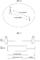
- FIG. 1 illustrates physical channels and a general signal transmission method using the physical channels, which may be used in embodiments of the present disclosure.
- the UE When a UE is powered on or enters a new cell, the UE performs initial cell search (S11).
- the initial cell search involves acquisition of synchronization to an eNB. Specifically, the UE synchronizes its timing to the eNB and acquires information such as a cell Identifier (ID) by receiving a Primary Synchronization Channel (P-SCH) and a Secondary Synchronization Channel (S-SCH) from the eNB.
- ID cell Identifier
- P-SCH Primary Synchronization Channel
- S-SCH Secondary Synchronization Channel
- the UE may acquire information broadcast in the cell by receiving a Physical Broadcast Channel (PBCH) from the eNB.
- PBCH Physical Broadcast Channel
- the UE may monitor a DL channel state by receiving a Downlink Reference Signal (DL RS).
- DL RS Downlink Reference Signal
- the UE may acquire more detailed system information by receiving a Physical Downlink Control Channel (PDCCH) and receiving a Physical Downlink Shared Channel (PDSCH) based on information of the PDCCH (S12).
- PDCCH Physical Downlink Control Channel
- PDSCH Physical Downlink Shared Channel
- the UE may perform a random access procedure with the eNB (S13 to S16).
- the UE may transmit a preamble on a Physical Random Access Channel (PRACH) (S13) and may receive a PDCCH and a PDSCH associated with the PDCCH (S14).
- PRACH Physical Random Access Channel
- the UE may additionally perform a contention resolution procedure including transmission of an additional PRACH (S15) and reception of a PDCCH signal and a PDSCH signal corresponding to the PDCCH signal (S16).
- the UE may receive a PDCCH and/or a PDSCH from the eNB (S17) and transmit a Physical Uplink Shared Channel (PUSCH) and/or a Physical Uplink Control Channel (PUCCH) to the eNB (S18), in a general UL/DL signal transmission procedure.
- PUSCH Physical Uplink Shared Channel
- PUCCH Physical Uplink Control Channel
- the UCI includes a Hybrid Automatic Repeat and reQuest Acknowledgement/Negative Acknowledgement (HARQ-ACK/NACK), a Scheduling Request (SR), a Channel Quality Indicator (CQI), a Precoding Matrix Index (PMI), a Rank Indicator (RI), etc.
- HARQ-ACK/NACK Hybrid Automatic Repeat and reQuest Acknowledgement/Negative Acknowledgement
- SR Scheduling Request
- CQI Channel Quality Indicator
- PMI Precoding Matrix Index
- RI Rank Indicator
- UCI is generally transmitted on a PUCCH periodically. However, if control information and traffic data should be transmitted simultaneously, the control information and traffic data may be transmitted on a PUSCH. In addition, the UCI may be transmitted aperiodically on the PUSCH, upon receipt of a request/command from a network.
- FIG. 2 illustrates exemplary radio frame structures used in embodiments of the present disclosure.
- FIG. 2(a) illustrates frame structure type 1.
- Frame structure type 1 is applicable to both a full Frequency Division Duplex (FDD) system and a half FDD system.
- FDD Frequency Division Duplex
- One subframe includes two successive slots.
- An ith subframe includes 2ith and (2i+1)th slots. That is, a radio frame includes 10 subframes.
- a time required for transmitting one subframe is defined as a Transmission Time Interval (TTI).
- One slot includes a plurality of Orthogonal Frequency Division Multiplexing (OFDM) symbols or SC-FDMA symbols in the time domain by a plurality of Resource Blocks (RBs) in the frequency domain.
- OFDM Orthogonal Frequency Division Multiplexing
- RBs Resource Blocks
- a slot includes a plurality of OFDM symbols in the time domain. Since OFDMA is adopted for DL in the 3GPP LTE system, one OFDM symbol represents one symbol period. An OFDM symbol may be called an SC-FDMA symbol or symbol period. An RB is a resource allocation unit including a plurality of contiguous subcarriers in one slot.
- each of 10 subframes may be used simultaneously for DL transmission and UL transmission during a 10-ms duration.
- the DL transmission and the UL transmission are distinguished by frequency.
- a UE cannot perform transmission and reception simultaneously in a half FDD system.
- the above radio frame structure is purely exemplary.
- the number of subframes in a radio frame, the number of slots in a subframe, and the number of OFDM symbols in a slot may be changed.
- FIG. 2(b) illustrates frame structure type 2.
- Frame structure type 2 is applied to a Time Division Duplex (TDD) system.
- TDD Time Division Duplex
- a type-2 frame includes a special subframe having three fields, Downlink Pilot Time Slot (DwPTS), Guard Period (GP), and Uplink Pilot Time Slot (UpPTS).
- DwPTS Downlink Pilot Time Slot
- GP Guard Period
- UpPTS Uplink Pilot Time Slot
- the DwPTS is used for initial cell search, synchronization, or channel estimation at a UE
- the UpPTS is used for channel estimation and UL transmission synchronization with a UE at an eNB.
- the GP is used to cancel UL interference between a UL and a DL, caused by the multi-path delay of a DL signal.
- FIG. 3 illustrates an exemplary structure of a DL resource grid for the duration of one DL slot, which may be used in embodiments of the present disclosure.
- a DL slot includes a plurality of OFDM symbols in the time domain.
- One DL slot includes 7 OFDM symbols in the time domain and an RB includes 12 subcarriers in the frequency domain, to which the present disclosure is not limited.
- Each element of the resource grid is referred to as a Resource Element (RE).
- An RB includes 12x7 REs.
- the number of RBs in a DL slot, NDL depends on a DL transmission bandwidth.
- a structure of an uplink slot may be identical to a structure of a downlink slot.
- FIG. 4 illustrates a structure of a UL subframe which may be used in embodiments of the present disclosure.
- a UL subframe may be divided into a control region and a data region in the frequency domain.
- a PUCCH carrying UCI is allocated to the control region and a PUSCH carrying user data is allocated to the data region.
- a UE does not transmit a PUCCH and a PUSCH simultaneously.
- a pair of RBs in a subframe is allocated to a PUCCH for a UE.
- the RBs of the RB pair occupy different subcarriers in two slots. Thus it is said that the RB pair frequency-hops over a slot boundary.
- FIG. 5 illustrates a structure of a DL subframe that may be used in embodiments of the present disclosure.
- DL control channels defined for the 3GPP LTE system include a Physical Control Format Indicator Channel (PCFICH), a PDCCH, and a Physical Hybrid ARQ Indicator Channel (PHICH).
- PCFICH Physical Control Format Indicator Channel
- PDCCH Physical Downlink Control Channel
- PHICH Physical Hybrid ARQ Indicator Channel
- the PCFICH is transmitted in the first OFDM symbol of a subframe, carrying information about the number of OFDM symbols used for transmission of control channels (i.e. the size of the control region) in the subframe.
- the PHICH is a response channel to a UL transmission, delivering an HARQ ACK/NACK signal.
- Control information carried on the PDCCH is called Downlink Control Information (DCI).
- the DCI transports UL resource assignment information, DL resource assignment information, or UL Transmission (Tx) power control commands for a UE group.
- an LTE-U system means an LTE system that supports such a CA status of a licensed band and an unlicensed band.
- a WiFi band or Bluetooth (BT) band may be used as the unlicensed band.
- LTE-A system operating on an unlicensed band is referred to as LAA (Licensed Assisted Access) and the LAA may correspond to a scheme of performing data transmission/reception in an unlicensed band using a combination with a licensed band.
- FIG. 6 illustrates an example of a CA environment supported in an LTE-U system.
- a UE is configured to perform wireless communication in each of a licensed band and an unlicensed band by using two CCs.
- the methods which will be described hereinafter may be applied to even a case where three or more CCs are configured for a UE.
- a carrier of the licensed band may be a primary CC (PCC or PCell), and a carrier of the unlicensed band may be a secondary CC (SCC or SCell).
- PCC primary CC
- SCC secondary CC
- the embodiments of the present disclosure may be applied to even a case where a plurality of licensed bands and a plurality of unlicensed bands are used in a carrier aggregation method.
- the methods suggested in the present disclosure may be applied to even a 3GPP LTE system and another system.
- one eNB supports both a licensed band and an unlicensed band. That is, the UE may transmit and receive control information and data through the PCC which is a licensed band, and may also transmit and receive control information and data through the SCC which is an unlicensed band.
- the status shown in FIG. 6 is only example, and the embodiments of the present disclosure may be applied to even a CA environment that one UE accesses a plurality of eNBs.
- the UE may configure a macro eNB (M-eNB) and a PCell, and may configure a small eNB (S-eNB) and an SCell.
- M-eNB macro eNB
- S-eNB small eNB
- SCell small eNB
- the macro eNB and the small eNB may be connected with each other through a backhaul network.
- the unlicensed band may be operated in a contention-based random access method.
- the eNB that supports the unlicensed band may perform a Carrier Sensing (CS) procedure prior to data transmission and reception.
- CS Carrier Sensing
- the CS procedure determines whether a corresponding band is reserved by another entity.
- the eNB of the SCell checks whether a current channel is busy or idle. If it is determined that the corresponding band is idle state, the eNB may transmit a scheduling grant to the UE to allocate a resource through (E)PDCCH of the PCell in case of a cross carrier scheduling mode and through PDCCH of the SCell in case of a self-scheduling mode, and may try data transmission and reception.
- E E
- PDCCH Physical Downlink Control Channel
- the eNB may configure a TxOP including N consecutive subframes.
- a value of N and a use of the N subframes may previously be notified from the eNB to the UE through higher layer signaling through the PCell or through a physical control channel or physical data channel.
- a CS procedure may be called a Clear Channel Assessment (CCA) procedure.
- CCA Clear Channel Assessment
- SCell it may be determined whether the channel is busy or idle. If the channel is determined to be idle, an eNB may start signal transmission in the SCell. This procedure may be referred to as LBT.
- FIG. 7 is a view illustrating an exemplary Frame Based Equipment (FBE) operation as one of LBT operations.
- FBE Frame Based Equipment
- the European Telecommunication Standards Institute (ETSI) regulation (EN 301 893 V1.7.1) defines two LBT operations, Frame Based Equipment (FBE) and Load Based Equipment (LBE).
- FBE Frame Based Equipment
- LBE Load Based Equipment
- one fixed frame is comprised of a channel occupancy time (e.g., 1 to 10ms) being a time period during which a communication node succeeding in channel access may continue transmission, and an idle period being at least 5% of the channel occupancy time
- CCA is defined as an operation for monitoring a channel during a CCA slot (at least 20 ⁇ s) at the end of the idle period.
- a communication node periodically performs CCA on a per-fixed frame basis. If the channel is unoccupied, the communication node transmits data during the channel occupancy time. On the contrary, if the channel is occupied, the communication node defers the transmission and waits until the CCA slot of the next period.
- FIG. 8 is a block diagram illustrating the FBE operation.
- a communication node i.e., eNB managing an SCell performs CCA during a CCA slot [S810]. If the channel is idle [S820], the communication node performs data transmission (Tx) [S830]. If the channel is busy, the communication node waits for a time period calculated by subtracting the CCA slot from a fixed frame period, and then resumes CCA [S840].
- the communication node transmits data during the channel occupancy time [S850]. Upon completion of the data transmission, the communication node waits for a time period calculated by subtracting the CCA slot from the idle period [S860], and then resumes CCA [S810]. If the channel is idle but the communication node has no transmission data, the communication node waits for the time period calculated by subtracting the CCA slot from the fixed frame period [S840], and then resumes CCA [S810].
- FIG. 9 is a view illustrating an exemplary LBE operation as one of the LBT operations.
- the communication node first sets q (q ⁇ ⁇ 4, 5, ..., 32 ⁇ ) and then performs CCA during one CCA slot.
- FIG. 9(b) is a block diagram illustrating the LBE operation. The LBE operation will be described with reference to FIG. 9(b) .
- the communication node may perform CCA during a CCA slot [S910]. If the channel is unoccupied in a first CCA slot [S920], the communication node may transmit data by securing a time period of up to (13/32)q ms [S930].
- the communication node selects N (N ⁇ ⁇ 1, 2, ..., q ⁇ ) arbitrarily (i.e., randomly) and stores the selected N value as an initial count. Then, the communication node senses a channel state on a CCA slot basis. Each time the channel is unoccupied in one specific CCA slot, the communication node decrements the count by 1. If the count is 0, the communication node may transmit data by securing a time period of up to (13/32)q ms [S940].
- the discontinuous transmission may influence on several functions necessary for performing an operation of LTE system.
- the several functions can be supported by one or more signals transmitted at a starting part of discontinuous LAA DL transmission.
- the functions supported by the signals include such a function as AGC configuration, channel reservation, and the like.
- channel reservation When a signal is transmitted by an LAA node, channel reservation has a meaning of transmitting signals via channels, which are occupied to transmit a signal to other nodes, after channel access is performed via a successful LBT operation.
- the functions which are supported by one or more signals necessary for performing an LAA operation including discontinuous DL transmission, include a function for detecting LAA DL transmission transmitted by a UE and a function for synchronizing frequency and time. In this case, the requirement of the functions does not mean that other available functions are excluded.
- the functions can be supported by other methods.
- a design target recommended by LAA system is to support a UE to make the UE obtain time and frequency synchronization via a discovery signal for measuring RRM (radio resource management) and each of reference signals included in DL transmission bursts, or a combination thereof.
- the discovery signal for measuring RRM transmitted from a serving cell can be used for obtaining coarse time or frequency synchronization.
- LAA When a DL LAA is designed, it may follow a CA timing relation between serving cells combined by CA, which is defined in LTE-A system (Rel-12 or earlier), for subframe boundary adjustment. Yet, it does not mean that a base station starts DL transmission only at a subframe boundary. Although all OFDM symbols are unavailable in a subframe, LAA system can support PDSCH transmission according to a result of an LBT operation. In this case, it is required to support transmission of control information necessary for performing the PDSCH transmission.
- the LTE-A system can transmit a discovery signal at a start point for supporting RRM functions including a function for detecting a cell.
- the discovery signal can be referred to as a discovery reference signal (DRS).
- DRS discovery reference signal
- the discovery signal of the LTE-A system and transmission/reception functions of the discovery signal can be applied in a manner of being changed.
- a DRS of LTE-A system is designed to support on/off operations of a small cell.
- off small cells correspond to a state that most of functions are turned off except a periodic transmission of a DRS.
- DRSs are transmitted at a DRS transmission occasion with a period of 40, 80, or 160 ms.
- a DMTC (discovery measurement timing configuration) corresponds to a time period capable of anticipating a DRS received by a UE. The DRS transmission occasion may occur at any point in the DMTC.
- a UE can anticipate that a DRS is continuously transmitted from a cell allocated to the UE with a corresponding interval.
- a DRS of LTE-A system may bring new constraints. For example, although transmission of a DRS such as a very short control transmission without LBT can be permitted in several regions, a short control transmission without LBT is not permitted in other several regions. Hence, a DRS transmission in the LAA system may become a target of LBT.
- the DRS When a DRS is transmitted, if LBT is applied to the DRS, similar to a DRS transmitted in LTE-A system, the DRS may not be transmitted by a periodic scheme. In particular, it may consider two schemes described in the following to transmit a DRS in the LAA system.
- a DRS is transmitted at a fixed position only in a DMTC configured on the basis of a condition of LBT.
- a DRS transmission is permitted at one or more different time positions in a DMTC configured on the basis of a condition of LBT.
- the number of time positions can be restricted to one time position in a subframe. If it is more profitable, DRS transmission can be permitted at the outside of a configured DMTC as well as DRS transmission performed in the DMTC.
- FIG. 10 is a diagram for explaining DRS transmission methods supported by LAA system.
- the upper part of FIG. 10 shows the aforementioned first scheme for transmitting a DRS and the bottom part of FIG. 10 shows the aforementioned second scheme for transmitting a DRS.
- a UE can receive a DRS at a position determined in a DMTC period only.
- a UE can receive a DRS at a random position in a DMTC period.
- the UE when a UE performs RRM measurement based on DRS transmission, the UE can perform single RRM measurement based on a plurality of DRS occasions.
- a DRS in LAA system, due to the constraint of LBT, it is difficult to guarantee that the DRS is transmitted at a specific position. Even though a DRS is not actually transmitted from a base station, if a UE assumes that the DRS exists, quality of an RRM measurement result reported by the UE can be deteriorated.
- LAA DRS when LAA DRS is designed, it is necessary to permit the existence of a DRS to be detected in a single DRS occasion. By doing so, it may be able to make the UE combine the existence of the DRS with RRM measurement, which is performed on successfully detected DRS occasions only.
- Signals including a DRS do not guarantee DRS transmissions adjacent in time.
- other nodes While operating in an unlicensed band, other nodes may sense that a corresponding channel is in an idle state during a silence period between DRS transmissions.
- transmission bursts including a DRS signal are configured by adjacent OFDM symbols in which several signals are transmitted.
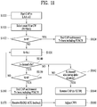
- FIG. 11 is a flowchart for explaining CAP and CWA.
- an LTE transmission node e.g., a base station
- LAA Scell(s) corresponding to an unlicensed band cell for DL transmission it may initiate a channel access procedure (CAP) [S1110].
- CAP channel access procedure
- the base station can randomly select a back-off counter N from a contention window (CW).
- the N is configured by an initial value Ninit [S1120].
- the Ninit is randomly selected from among values ranging from 0 to CW p .
- the base station terminates the CAP and performs Tx burst transmission including PSCH [S1124]. On the contrary, if the back-off value is not 0, the base station reduces the back-off counter value by 1 [S1130].
- the base station checks whether or not a channel of the LAA Scell(s) is in an idle state [S1140]. If the channel is in the idle state, the base station checks whether or not the back-off value corresponds to 0 [S1150]. The base station repeatedly checks whether or not the channel is in the idle state until the back-off value becomes 0 while reducing the back-off counter value by 1.
- the base station checks whether or not the channel is in the idle state during a defer duration (more than 15 usec) longer than a slot duration (e.g., 9 usec) [S1142]. If the channel is in the idle state during the defer duration, the base station can resume the CAP [S1144]. For example, when the back-off counter value Ninit corresponds to 10, if the channel state is determined as busy after the back-off counter value is reduced to 5, the base station senses the channel during the defer duration and determines whether or not the channel is in the idle state.
- the base station performs the CAP again from the back-off counter value 5 (or, from the back-off counter value 4 by reducing the value by 1) rather than configures the back-off counter value Ninit.
- the base station performs the step S1142 again to check whether or not the channel is in the idle state during a new defer duration.
- the base station checks whether or not the back-off counter value (N) becomes 0 [S1150]. If the back-off counter value (N) becomes 0, the base station terminates the CAP and may be able to transmit a Tx burst including PDSCH.
- the base station can receive HARQ-ACK information from a UE in response to the Tx burst [S1170].
- the base station can adjust a CWS (contention window size) based on the HARQ-ACK information received from the UE [S1180].
- the base station can adjust the CWS based on HARQ-ACK information on a first subframe of a most recently transmitted Tx burst (i.e., a start subframe of the Tx burst).
- the base station can set an initial CW to each priority class before the CWP is performed. Subsequently, if a probability that HARQ-ACK values corresponding to PDSCH transmitted in a reference subframe are determined as NACK is equal to or greater than 80 %, the base station increases CW values set to each priority class to a next higher priority.
- PDSCH can be assigned by a self-carrier scheduling scheme or a cross-carrier scheduling scheme. If the PDSCH is assigned by the self-carrier scheduling scheme, the base station counts DTX, NACK/DTX, or ANY state among the HARQ-ACK information fed back by the UE as NACK. If the PDSCH is assigned by the cross-carrier scheduling scheme, the base station counts the NACK/DTX and the ANY states as NACK and does not count the DTX state as NACK among the HARQ-ACK information fed back by the UE.
- the base station may consider the bundled HARQ-ACK information as M number of HARQ-ACK responses. In this case, it is preferable that a reference subframe is included in the M number of bundled subframes.
- LBT Listen-Before-Talk
- a base station or a UE should perform LBT to transmit a signal on an unlicensed band.
- the base station or the UE transmits a signal, it is necessary to make signal interference not to be occurred with different communication nodes such as Wi-Fi, and the like.
- a CCA threshold value is regulated by -62dBm and -82dBm for a non-Wi-Fi signal and a Wi-Fi signal, respectively.
- an STA station
- an AP access point
- the STA or the AP does not perform signal transmission.
- a UE operating on the unlicensed band may maintain access with a different cell operating on a licensed band to stably control mobility, RRM (radio resource management) function, and the like.
- RRM radio resource management
- a cell accessed by a UE on the unlicensed band is referred to as a U-Scell (or LAA Scell) and a cell accessed by the UE on the licensed band is referred to as a Pcell.
- LAA licensed assisted access
- a length of a defer period, a CWS, MCOT (maximum channel occupancy time), and the like are defined according to each of the channel access priority classes.
- the maximum channel occupancy time (MCOT) is determined by 2/3/8/8 ms.
- the maximum channel occupancy time (MCOT) is determined by 2/3/10/10 ms in environment where other RAT such as Wi-Fi does not exists (e.g., by level of regulation).
- a set of CWSs capable of being configured according to a class is defined.
- One of points different from Wi-Fi system is in that a different backoff counter value is not defined according to a channel access priority class and LBT is performed using a single backoff counter value (this is referred to as single engine LBT).
- CWS values of all classes are initialized by CWmin irrespective of a CWS value of the triggering timing.
- FIG. 12 is a diagram illustrating a partial TTI or a partial subframe applicable to the present invention.
- MCOT is utilized as much as possible when DL Tx burst is transmitted.
- a partial TTI which is defined as DwPTS.
- the partial TTI corresponds to a section in which a signal is transmitted as much as a length shorter than a legacy TTI (e.g., 1ms) when PDSCH is transmitted.
- a starting partial TTI or a starting partial subframe corresponds to a form that a part of symbols positioned at the fore part of a subframe are emptied out.
- An ending partial TTI or an ending partial subframe corresponds to a form that a part of symbols positioned at the rear part of a subframe are emptied out. (On the contrary, an intact TTI is referred to as a normal TTI or a full TTI.)
- FIG. 12 illustrates various types of the aforementioned partial TTI.
- the first drawing of FIG. 12 illustrates an ending partial TTI (or subframe) and the second drawing illustrates a starting partial TTI (or subframe).
- the third drawing of FIG. 12 illustrates a partial TTI (or subframe) that a part of symbols positioned at the fore part and the rear part of a subframe are emptied out.
- TX gap transmission gap
- a partial TTI structure shown in FIG. 12 can be applied to a form of transmitting PUCCH or PUSCH as well.
- the present invention proposes a method of transmitting and receiving a signal (DwPTS, SRS (Sounding Reference Signal), etc.) in a situation that carriers including carriers of an unlicensed band are aggregated.
- a signal DwPTS, SRS (Sounding Reference Signal), etc.
- an ending partial subframe illustrated in FIG. 12 has been introduced due to the reason described in the following.
- an ending partial subframe applicable to the present invention may have a structure identical to a DwPTS of a frame structure 2 (TDD).
- TDD frame structure 2
- Special subframe configuration Normal cyclic prefix in downlink Extended cyclic prefix in downlink DwPTS UpPTS DwPTS UpPTS Normal cyclic prefix in uplink Extended cyclic prefix in uplink Normal cyclic prefix in uplink Extended cyclic prefix in uplink 0 6592 ⁇ T s (1 + X) ⁇ 2192 ⁇ T s (1 + X) ⁇ 2560 ⁇ T s 7680 ⁇ T s (1 + X) ⁇ 2192 ⁇ T s (1 + X) ⁇ 2560 ⁇ T s 1 19760 ⁇ T s 20480 ⁇ T s 2 21952 ⁇ T s 23040 ⁇ T s 3 24144 ⁇ T s 25600 ⁇ T s 4 26336 ⁇ T s 25600 ⁇ T s 4 26336 ⁇ T s 25600 ⁇ T s 4 26336 ⁇ T
- the number of PDCCH symbols of an ending partial subframe can be configured by maximum 2 symbols.
- a DwPTS is configured by 3 symbols
- PDSCH is not transmitted during the DwPTS
- PDCCH/CRS Cell-specific Reference Signal
- PSS Primary Synchronization Signal
- a PSS can be transmitted at the last symbol of the first slot of an SF #0/5 (or a DRS (Discovery Reference Signal) SF).
- SF #0/5 or a DRS (Discovery Reference Signal) SF.
- a DwPTS having a length of 3 symbols is transmitted in the LAA Scell to which the present invention is applicable, a DL signal or a channel expected by a UE may not exist in the last 3 rd symbol.
- the present invention proposes a method of efficiently utilizing the remaining resource in the following.
- the present invention proposes a method of allowing maximum 3 symbols of a PDCCH region to a DwPTS having a length of 3 symbols.
- the number of OFDM symbols constructing a PDCCH may correspond to minimum 1 to maximum 3.
- a size of a corresponding scheduling grant may increase.
- a PDCCH region is getting bigger, it is more profitable in the aspect of multi-SF scheduling transmission flexibility.
- it may be able to allow a PDCCH region to have a symbol length as many as maximum 3 symbols not only for a DwPTS having a length of 3 symbols but also for a general DwPTS.
- the number of REs available for PDSCH in a DwPTS can be decreased due to the increased number of PDCCH symbols, thereby considerably decreasing a coding rate.
- it may be able to introduce a scaling factor smaller than a legacy scaling factor to a DwPTS.
- a scaling factor value 0.6 is applied for special subframe configurations 1/2/3/4/6/7/8 and a scaling factor value 0.3 can be applied for a special subframe configuration 9.
- it may be able to introduce a scaling factor smaller than a legacy scaling factor only when a length of PDCCH in a DwPTS corresponds to 3 symbols.
- the present invention proposes a method of correcting a length using a DwPTS of a length of 2 symbols instead of a DwPTS of a length of 3 symbols.
- it may be able to introduce an ending partial subframe having a length of 4400 T_s instead of a special subframe configuration 0/5.
- a common PDCCH has been introduced to indicate an OFDM symbol length of an ending partial subframe in a subframe immediately before the ending partial subframe and the ending partial subframe.
- 'Subframe configuration for LAA' field constructing the common PDCCH is shown in Table 5 in the following.
- a configuration corresponding to '0110' can be changed with (-,2) and a configuration corresponding to '1101' can be changed with (2,-). By doing so, it is able to minimize dummy signal transmission of an eNB.
- - (X,-) means UE may assume the first X symbols are occupied in current subframe and other symbols in the current subframe are not occupied.
- - (X,*) means UE may assume the first X symbols are occupied in current subframe, and at least the first OFDM symbol of the next subframe is not occupied.
- a UE can transmit an SRS at the last symbol of a specific subframe.
- the specific subframe may correspond to an ending partial subframe or a normal UL subframe.
- the UE can transmit an SRS in the last symbol of an ending partial subframe or can transmit an SRS in the last symbol of a normal UL subframe.
- LBT type 1 LBT
- LBT type 2 CCA-based LBT
- LBT type 3 CCA-based LBT
- SRS triggering can be performed by at least one selected from the group consisting of a DL grant, a UL grant, and a common PDCCH.
- the LBT can also be indicated by a DL grant, a UL grant, a common PDCCH, and the like.
- the LBT can be commonly applied not only to an SRS but also to a different UL channel (PRACH, PUSCH, PUCCH, etc.).
- the present invention proposes a method of determining an LBT type according to a length of the ending partial subframe.
- an LBT type performed by a UE can be configured by an LBT type A.
- the LBT can be configured by an LBT type B.
- the UE may attempt to perform an LBT type 1.
- the UE may attempt to perform an LBT type 2. Or, it may be able to configure the UE to perform the abovementioned LBT.
- the present invention proposes a method of applying an LBT parameter corresponding to a specific priority class among channel access priority classes set to the LBT type 3 in advance.
- LBT type 3 random backoff-based LBT
- the UE attempts to perform LBT to which an LBT parameter corresponding to a priority class selected from among the predetermined channel access priority classes and can perform SRS transmission based on a result of the LBT.
- the LBT type 3 can be indicated by a DL grant, a UL grant, a common PDCCH, or the like. If no LBT type is indicated by the DL grant, the UL grant, the common PDCCH, or the like, a default LBT type can be configured.
- an applicable CWS set may correspond to ⁇ 3,7 ⁇ .
- 3 or 7 corresponding to one of values of the CWS set values can be applied as a CWS value applied to the LBT to transmit an SRS.
- priority class 3 is configured by RRC signaling as an LBT parameter for the LBT and ⁇ 15,31 ⁇ among ⁇ 15,31,63 ⁇ can be applied only as a CWS set applied to the LBT.
- the CWS set can be configured by RRC signaling.
- a CWS is increased whenever SRS transmission fails and a CWS is reset whenever SRS transmission succeeds irrespective of whether or not a CWS is adjusted for PUSCH.
- a UE may be able to define a rule that a UE performs LBT by utilizing a CWS corresponding to a most recently used CWS to transmit PUSCH.
- a CWS value of LBT for transmitting an SRS is configured based on a priority class 2
- a UE in order to transmit an SRS, a UE can perform LBT based on a CWS identical to a priority class 2-related CWS most recently used for transmitting PUSCH.
- a CWS value of LBT for transmitting an SRS can be determined in consideration of whether the CWS value applied to the LBT corresponds to a configured CWmin or an increased CWS only irrespective of a priority class of LBT most recently applied by a UE to transmit PUSCH.
- a CWS value of LBT for transmitting an SRS when a CWS value of LBT for transmitting an SRS is configured based on a priority class 2, although a CWS of LBT most recently applied by a UE to transmit PUSCH corresponds to a CWS of a priority class 3, a CWS value of LBT for transmitting an SRS can be configured based on a minimum value or an increased CWS among configured values according to whether the CWS value corresponds to CWmin or an increased CWS.
- a UE can perform LBT by identically utilizing a CWS most recently applied to LBT for transmitting PUSCH irrespective of a priority class of LBT for transmitting an SRS.
- the abovementioned first to third LBT methods can be utilized not only for SRS transmission but also for PUSCH/PUCCH/PRACH transmission after DwPTS (i.e., UpPTS position).
- DwPTS i.e., UpPTS position
- the PUSCH/PUCCH/PRACH can be configured by a partial subframe only shorter than 1 ms between DwPTS + GP (guard period) and a next subframe boundary.
- FIG. 13 is a diagram for explaining an operation of a UE when the UE is scheduled to transmit PUSCH in an SF #n+1 after the UE transmits an SRS in the last symbol of an SF #n according to one embodiment of the present invention.
- a starting position of the PUSCH can be indicated by a position appearing after 25 usec or 25 usec + TA (Timing Advance) from a boundary of the SF #n+1 in the SF #n+1.
- a UE it is necessary to consider whether or not a UE is able to perform all operations including an operation of switching into a reception operation (e.g., TX -> RX switching) and LBT (e.g., 25 usec LBT) (in addition, switching into a transmission operation (e.g., RX -> TX switching)) during a short gap as much as 25 usec or 25 usec + TA.
- a reception operation e.g., TX -> RX switching
- LBT e.g., 25 usec LBT
- switching into a transmission operation e.g., RX -> TX switching
- the switching into the transmission operation (e.g., RX -> TX switching) can be included in PUSCH transmission time in the SF #n+1.
- the present invention proposes a method for a UE to transmit an SRS in the SF #n and transmit PUSCH in the SF #n+1 in the abovementioned situation.
- the present invention proposes a method of setting a limit on a gap size between two subframes with a value of 25 usec (+ TA).
- the UE may expect DFTS-OFDM symbol #0 or DFTS-OFDM symbol #1 only as signaling for a PUSCH starting position of the SF #n+1.
- a PUSCH starting position is indicated by a position appearing after 25 usec or 25 usec + TA from SF #n+1 boundary, it may be difficult for a scheduled UE to perform all operations including switching to a reception operation (TX -> RX switching) + 25 usec LBT (+ switching into a transmission operation (RX -> TX switching)) during a gap between an indicated SRS and PUSCH.
- the present invention proposes a method for a UE to start PUSCH transmission from the timing at which a reception operation (TX -> RX switching) + 25 usec LBT (+ switching into a transmission operation (RX -> TX switching)) are completed.
- a UE can transmit an initial signal (e.g., a predetermined signal such as DM-RS/SRS, a part (extension of a CP (cyclic prefix)) of PUSCH to be transmitted in the DFTS-OFDM symbol #1 from the timing.
- an initial signal e.g., a predetermined signal such as DM-RS/SRS, a part (extension of a CP (cyclic prefix)
- a scheduled UE if it is difficult for a scheduled UE to perform all operations including switching to a reception operation (TX -> RX switching) + 25 usec LBT (+ switching into a transmission operation (RX -> TX switching)) during a gap between an indicated SRS and PUSCH, it is able to define a rule that the UE attempts to transmit PUSCH from the DFTS-OFDM symbol #1 boundary.
- the present invention proposes a method of indicating a PUSCH starting position by a position appearing after X us.
- a value of the X is configured via higher layer signaling or can be differently configured according to capability signaling reported by a UE.
- a UE can transmit PUSCH in the SF #n+1 after switching to a reception operation (TX -> RX switching) + 25 usec LBT (+ switching into a transmission operation (RX -> TX switching)) are performed.
- signaling indicating that the PUSCH starting position corresponds to a position appearing after the X us from a subframe boundary can be additionally introduced to signaling indicating a legacy PUSCH starting position (e.g., DFTS-OFDM symbol #0, DFTS-OFDM symbol #0+25 usec, DFTS-OFDM symbol #0+25 usec+TA, or DFTS-OFDM symbol #1).
- a legacy PUSCH starting position e.g., DFTS-OFDM symbol #0, DFTS-OFDM symbol #0+25 usec, DFTS-OFDM symbol #0+25 usec+TA, or DFTS-OFDM symbol #1.
- the PUSCH starting position when the PUSCH starting position is indicated by DFTS-OFDM symbol #0+25 usec (and/or DFTS-OFDM symbol #0+25 usec+TA), the PUSCH starting position can be configured to be interpreted as DFTS-OFDM symbol #0+X usec only when an SRS is scheduled in an SF #n and a PUSCH is scheduled in an SF #n+1.
- the present invention proposes a method of making an on/off power transient period to be absorbed in an SRS symbol by changing a power mask of an SRS. In other word, the present invention proposes a method of including the on/off power transient period in an SRS symbol period.
- time for switching to the transmission operation is absorbed (or included) in SF #n+1 PUSCH period and time for switching to the reception operation can be absorbed (or included) in SF #n SRS symbol period.
- a PUSCH starting position is indicated by a position appearing after 25 usec or 25 usec + TA from SF #n+1 boundary, a UE according to the present invention can easily implement a corresponding operation.
- the present invention propose a method of allowing a UE to transmit an initial signal from the last symbol boundary prior to a subframe in which a scheduled PUSCH is transmitted and a method of introducing signaling for supporting the method.
- an eNB that schedules a small gap of 25 used or 25 usec + TA between an SRS and a following PUSCH, it may additionally consider a multiplexing method with a different UE transmitting a signal in an SF #n+1 (not transmitting an SRS in an SF #n).
- a UE 1 configured to transmit SF #n SRS + SF #n+1 is scheduled to make no gap between an SRS and a PUSCH.
- a UE 2 configured to transmit SF #n+1 PUSCH only can be indicated to transmit an initial signal from the last symbol of the SF #n.
- the initial signal it may apply a predetermined signal such as DM-RS/SRS or a part (extension of a CP (cyclic prefix)) of PUSCH to be transmitted in DFTS-OFDM symbol #0 of the SF #n.
- the present invention proposes a method of including a power transient period in a small gap of 25 usec or 25 usec + TA.
- a short transmission-reception transition TX-RX transition
- the present invention proposes a method of including a power transient period in a small gap of 25 usec or 25 usec + TA.
- an on/off power transient period of an SRS is to be absorbed (included) in a part of a small gap of 25 usec or 25 usec + TA in SF #n and a UE performs CCA in a remaining period only.
- the aforementioned first to sixth methods of transmitting an SRS and a PUSCH can be identically applied not only to a case that a UE is scheduled to transmit an SRS in SF #n and transmit PUSCH in SF #n+1 but also to a case that the UE is scheduled to transmit PUSCH in the SF #n and transmit PUSCH in the SF #n+1.
- the UE can transmit the PUSCH in the SF #n and transmit the PUSCH in the SF #n+1 by applying a method similar to the first to sixth methods of transmitting SRS and PUSCH.
- time for switching to the transmission operation is absorbed (or included) in SF #n+1 PUSCH duration and time for switching to the reception operation can be absorbed (or included) in SF #n PUSCH duration.
- LAA Scell to which the present invention is applicable, it is able to allow a plurality of UL subframes to be scheduled in single DCI. To this end, unlike a DCI format 0/4 scheduling a legacy UL subframe, it is able to define a new DCI format 0A/0B/4A/4B.
- the DCI format 0A/0B can be used for scheduling 1 TB (transmission block) and the DCI format 4A/4B can be used for scheduling 2 TBs.
- the DCI format 0A/4A can be used for scheduling a single UL subframe and the DCI format 0B/4B can be used for scheduling maximum 4 UL subframes at a time.
- the maximum number of subframes capable of being scheduled by the DCI format 0B/4B can be configured via RRC signaling and the number of subframes can be configured by a value selected from among 2 to 4.
- the number of subframes equal to or less than the maximum value can be actually scheduled according to DCI.
- the number of actually scheduled subframes can be dynamically indicated via a UL grant.
- the DCI format 0B/4B can signal a PUSCH starting position and can indicate a PUSCH starting gap not only for a first subframe but also for the remaining subframes among a plurality of UL subframes scheduled at the same time.
- a position of a subframe in which an SRS is to be transmitted can be indicated by a legacy "SRS request" bit field and a subframe position to be transmitted among information corresponding to each state can be configured to be indicated via RRC signaling.
- a PUSCH starting position of a subframe(s) to which a PUSCH starting gap is indicated can be configured to be determined by a different rule according to a subframe in which an SRS is transmitted.
- a starting gap is indicated to a subframe (e.g., SF #n+1) appearing after a subframe (e.g., SF #n) in which an SRS is transmitted
- a DFTS-OFDM symbol #0+25 usec or a DFTS-OFDM symbol #0+25 usec + TA is applied as a starting position of the SF #2/4. In this case, it may apply a DFTS-OFDM symbol #1 as a starting position of the SF #3.
- a DCI format 0B/4B indicates 4 subframes including SF #1/2/3/4 to be scheduled, assume a case that a starting gap is indicated to all of the 4 subframes.
- SRS transmission is indicated in the SF #2, it may apply a DFTS-OFDM symbol #1 as a starting position of the SF #2/3/4.
- the present invention proposes a method for a UE to transmit an SRS in the following.
- a UE Due to the characteristic of an unlicensed band, a UE performs LBT to transmit an SRS. If the LBT succeeds, the UE can transmit the SRS.
- the SRS transmission may apply random backoff-based LBT based on a predetermined channel access priority class.
- the SRS transmission can be performed in the last symbol in time dimension among symbols included in a subframe.
- LBT when LBT is performed to transmit an SRS without PUSCH, it may apply random backoff-based LBT based on a channel access priority class having a smallest contention widow size among a plurality of channel access priority classes configured in a system.
- the UE when a UE intends to perform SRS transmission only without transmitting PUSCH, the UE can perform LBT of a highest success rate among random backoff based LBTs to transmit an SRS.
- LBT when LBT is performed to transmit an SRS without transmitting PUSCH, it may apply random backoff-based LBT based on a channel access priority class having a value of ⁇ 3,7 ⁇ as an allowed contention window size.
- a contention window size applied to the LBT for performing SRS transmission without PUSCH can be differently applied according to whether a contention window size recently applied to LBT for transmitting PUSCH corresponds to a minimum contention window size or an increased contention window size.
- the contention window size recently applied to LBT for transmitting PUSCH corresponds to a minimum contention window size, it may apply 3 as a contention window size applied to the LBT for transmitting an SRS without PUSCH. Or, if the contention window size recently applied to LBT for transmitting PUSCH corresponds to an increased contention window size, it may apply 7 as a contention window size applied to the LBT for transmitting an SRS without PUSCH.
- an eNB informs a UE of information on whether to apply the proposed methods (or, information on rules of the proposed methods) via a predefined signal (e.g., physical layer signal or higher layer signal).
- a predefined signal e.g., physical layer signal or higher layer signal
- FIG. 14 is a diagram illustrating configurations of a UE and a base station capable of being implemented by the embodiments proposed in the present invention.
- a UE and a base station illustrated in FIG 14 operate to implement embodiments for a method of transmitting and receiving a sounding reference signal without a physical uplink shared channel between the UE and the base station.
- a UE 1 may act as a transmission end on a UL and as a reception end on a DL.
- a base station (eNB) 100 may act as a reception end on a UL and as a transmission end on a DL.
- each of the UE and the base station may include a Transmitter (Tx) 10 or 110 and a Receiver (Rx) 20 or 120, for controlling transmission and reception of information, data, and/or messages, and an antenna 30 or 130 for transmitting and receiving information, data, and/or messages.
- Tx Transmitter
- Rx Receiver
- Each of the UE and the base station may further include a processor 40 or 140 for implementing the afore-described embodiments of the present disclosure and a memory 50 or 150 for temporarily or permanently storing operations of the processor 40 or 140.
- the UE performs LBT for transmitting an SRS via the processor 4. If the LBT succeeds, the UE can transmit the SRS. In this case, if the SRS transmission does not include PUSCH transmission, it may apply random backoff-based LBT based on a predetermined channel access priority class.
- the Tx and Rx of the UE and the base station may perform a packet modulation/demodulation function for data transmission, a high-speed packet channel coding function, OFDM packet scheduling, TDD packet scheduling, and/or channelization.
- Each of the UE and the base station of FIG. 14 may further include a low-power Radio Frequency (RF)/Intermediate Frequency (IF) module.
- RF Radio Frequency
- IF Intermediate Frequency
- the UE may be any of a Personal Digital Assistant (PDA), a cellular phone, a Personal Communication Service (PCS) phone, a Global System for Mobile (GSM) phone, a Wideband Code Division Multiple Access (WCDMA) phone, a Mobile Broadband System (MBS) phone, a hand-held PC, a laptop PC, a smart phone, a Multi Mode-Multi Band (MM-MB) terminal, etc.
- PDA Personal Digital Assistant
- PCS Personal Communication Service
- GSM Global System for Mobile
- WCDMA Wideband Code Division Multiple Access
- MBS Mobile Broadband System
- hand-held PC a laptop PC
- smart phone a Multi Mode-Multi Band (MM-MB) terminal, etc.
- MM-MB Multi Mode-Multi Band
- the smart phone is a terminal taking the advantages of both a mobile phone and a PDA. It incorporates the functions of a PDA, that is, scheduling and data communications such as fax transmission and reception and Internet connection into a mobile phone.
- the MB-MM terminal refers to a terminal which has a multi-modem chip built therein and which can operate in any of a mobile Internet system and other mobile communication systems (e.g. CDMA 2000, WCDMA, etc.).
- Embodiments of the present disclosure may be achieved by various means, for example, hardware, firmware, software, or a combination thereof.
- the methods according to exemplary embodiments of the present disclosure may be achieved by one or more Application Specific Integrated Circuits (ASICs), Digital Signal Processors (DSPs), Digital Signal Processing Devices (DSPDs), Programmable Logic Devices (PLDs), Field Programmable Gate Arrays (FPGAs), processors, controllers, microcontrollers, microprocessors, etc.
- ASICs Application Specific Integrated Circuits
- DSPs Digital Signal Processors
- DSPDs Digital Signal Processing Devices
- PLDs Programmable Logic Devices
- FPGAs Field Programmable Gate Arrays
- processors controllers, microcontrollers, microprocessors, etc.
- the methods according to the embodiments of the present disclosure may be implemented in the form of a module, a procedure, a function, etc. performing the above-described functions or operations.
- a software code may be stored in the memory 180 or 190 and executed by the processor 120 or 130.
- the memory is located at the interior or exterior of the processor and may transmit and receive data to and from the processor via various known means.
- the embodiments of the present invention can be applied to various wireless access systems including 3GPP (3rd Generation Partnership Project) and 3GPP2 system.
- the embodiments of the present invention can be applied not only to various wireless access systems but also to all technical fields to which the various wireless access systems are applied.
- the proposed method can also be applied to an mmWave communication system using ultrahigh frequency band.
Landscapes
- Engineering & Computer Science (AREA)
- Signal Processing (AREA)
- Computer Networks & Wireless Communication (AREA)
- Power Engineering (AREA)
- Physics & Mathematics (AREA)
- Health & Medical Sciences (AREA)
- General Health & Medical Sciences (AREA)
- Spectroscopy & Molecular Physics (AREA)
- Mobile Radio Communication Systems (AREA)
Claims (4)
- Verfahren zum Übertragen eines Sondierungsreferenzsignals, SRS, durch ein Benutzergerät (1) an eine Basisstation (100) in einem Drahtloskommunikationssystem, das ein unlizenziertes Band unterstützt, wobei das Verfahren Folgendes umfasst:Durchführen einer Kanalzugangsprozedur, CAP (Channel Access Procedure), zum Übertragen des SRS über das unlizenzierte Band; undÜbertragen des SRS über das unlizenzierte Band basierend auf der CAP, wobei das Verfahren dadurch gekennzeichnet ist, dass:es sich bei der CAP, basierend auf der SRS-Übertragung ohne einen physischen gemeinsam genutzten Uplink-Kanal, PUSCH (Physical Uplink Shared Channel), in demselben Unterrahmen, um eine auf einem zufälligen Backoff basierende CAP handelt, die darauf basiert, dass eine vorbestimmte Kanalzugangsprioritätsklasse einen Wert von {3,7} als eine zulässige Konkurrenzfenstergröße aufweist,wobei, basierend darauf, dass eine zuletzt auf die CAP zum Übertragen des PUSCH angewendete Konkurrenzfenstergröße eine Mindestkonkurrenzfenstergröße ist, 3 als die auf die CAP zum Übertragen des SRS angewendete Konkurrenzfenstergröße angewendet wird, undwobei, basierend darauf, dass die zuletzt auf die CAP zum Übertragen des PUSCH angewendete Konkurrenzfenstergröße eine erhöhte Fenstergröße ist, 7 als die auf die CAP zum Übertragen des SRS angewendete Konkurrenzfenstergröße angewendet wird.
- Verfahren nach Anspruch 1, wobei das SRS im letzten Symbol unter in dem Unterrahmen enthaltenen Symbolen in einem Zeitbereich übertragen wird.
- Kommunikationsvorrichtung (1) zum Übertragen eines Sondierungsreferenzsignals, SRS, an eine Basisstation (100) in einem Drahtloskommunikationssystem, das ein unlizenziertes Band unterstützt, wobei die Kommunikationsvorrichtung (1) Folgendes umfasst:einen Speicher (50); undeinen Prozessor (40), der mit dem Speicher (50) betriebsgekoppelt ist und zu Folgendem ausgelegt ist:Durchführen einer Kanalzugangsprozedur, CAP, zum Übertragen des SRS über das unlizenzierte Band; undÜbertragen des SRS über das unlizenzierte Band basierend auf der CAP, und wobei die Kommunikationsvorrichtung dadurch gekennzeichnet ist, dass:es sich bei der CAP, basierend auf der SRS-Übertragung ohne einen physischen gemeinsam genutzten Uplink-Kanal, PUSCH, in einem Unterrahmen, um eine auf einem zufälligen Backoff basierende CAP handelt, die darauf basiert, dass eine vorbestimmte Kanalzugangsprioritätsklasse einen Wert von {3,7} als eine zulässige Konkurrenzfenstergröße aufweist,wobei, basierend darauf, dass eine zuletzt auf die CAP zum Übertragen des PUSCH angewendete Konkurrenzfenstergröße eine Mindestkonkurrenzfenstergröße ist, 3 als die auf die CAP zum Übertragen des SRS angewendete Konkurrenzfenstergröße angewendet wird, undwobei, basierend darauf, dass die zuletzt auf die CAP zum Übertragen des PUSCH angewendete Konkurrenzfenstergröße eine erhöhte Fenstergröße ist, 7 als die auf die CAP zum Übertragen des SRS angewendete Konkurrenzfenstergröße angewendet wird.
- Kommunikationsvorrichtung nach Anspruch 3, wobei das SRS im letzten Symbol unter in dem Unterrahmen enthaltenen Symbolen in einem Zeitbereich übertragen wird.
Applications Claiming Priority (4)
| Application Number | Priority Date | Filing Date | Title |
|---|---|---|---|
| US201662334381P | 2016-05-10 | 2016-05-10 | |
| US201662370719P | 2016-08-04 | 2016-08-04 | |
| US201662373345P | 2016-08-10 | 2016-08-10 | |
| PCT/KR2017/004790 WO2017196055A2 (ko) | 2016-05-10 | 2017-05-10 | 비면허 대역을 지원하는 무선 통신 시스템에서 사운딩 참조 신호를 전송하는 방법 및 이를 지원하는 장치 |
Publications (3)
| Publication Number | Publication Date |
|---|---|
| EP3439219A2 EP3439219A2 (de) | 2019-02-06 |
| EP3439219A4 EP3439219A4 (de) | 2019-11-20 |
| EP3439219B1 true EP3439219B1 (de) | 2020-12-30 |
Family
ID=60266553
Family Applications (1)
| Application Number | Title | Priority Date | Filing Date |
|---|---|---|---|
| EP17796355.0A Active EP3439219B1 (de) | 2016-05-10 | 2017-05-10 | Verfahren und vorrichtung zur übertragung eines sondierungsreferenzsignals in einem drahtlosenn, in einem unterstützten nichtlizenzierten frequenzband operierenden kommunikationssystem |
Country Status (4)
| Country | Link |
|---|---|
| US (4) | US11252764B2 (de) |
| EP (1) | EP3439219B1 (de) |
| CN (1) | CN109155713B (de) |
| WO (1) | WO2017196055A2 (de) |
Families Citing this family (14)
| Publication number | Priority date | Publication date | Assignee | Title |
|---|---|---|---|---|
| CN107580801B (zh) * | 2015-05-12 | 2021-03-30 | Lg 电子株式会社 | 在支持未授权带的无线接入系统中基于harq-ack信息调整竞争窗口大小的方法和支持该方法的设备 |
| EP3439219B1 (de) | 2016-05-10 | 2020-12-30 | LG Electronics Inc. -1- | Verfahren und vorrichtung zur übertragung eines sondierungsreferenzsignals in einem drahtlosenn, in einem unterstützten nichtlizenzierten frequenzband operierenden kommunikationssystem |
| CN110521158B (zh) * | 2017-03-24 | 2022-05-13 | 苹果公司 | 基站的装置、通信的方法、ue的基带处理器和用户设备 |
| US10855421B2 (en) * | 2017-08-10 | 2020-12-01 | Qualcomm Incorporated | Configuration of sounding reference signal resources in an uplink transmission time interval |
| WO2019033118A1 (en) * | 2017-08-11 | 2019-02-14 | Intel IP Corporation | BINDING QUALITY MANAGEMENT AND THE USE OF PARTIAL SUB-FRAMES IN WIRELESS TELECOMMUNICATION NETWORKS |
| CN107889164B (zh) * | 2017-11-23 | 2021-03-09 | Oppo广东移动通信有限公司 | 无线局域网分流处理方法以及相关产品 |
| JP2021510473A (ja) * | 2018-01-12 | 2021-04-22 | オッポ広東移動通信有限公司Guangdong Oppo Mobile Telecommunications Corp., Ltd. | 信号伝送方法及び装置 |
| US11223456B2 (en) * | 2018-02-20 | 2022-01-11 | Qualcomm Incorporated | Transmission gap configuration |
| CN110351048B (zh) * | 2018-04-04 | 2021-10-26 | 展讯通信(上海)有限公司 | 一种功率瞬变场景下上行传输的方法、系统及移动终端 |
| CN113519136A (zh) * | 2019-01-09 | 2021-10-19 | 苹果公司 | 用于在未许可频谱上操作的nr系统中基于cbg的重传的cat.4 lbt的竞争窗口大小更新 |
| US12089250B2 (en) | 2019-08-13 | 2024-09-10 | Nokia Technologies Oy | Channel access procedure based on channel access priority class |
| US11665700B2 (en) | 2020-02-07 | 2023-05-30 | Qualcomm Incorporated | Adaptive contention window and burst length for receiver based ECCA for MMWAVE band |
| EP4118900A4 (de) * | 2020-03-12 | 2023-12-06 | Qualcomm Incorporated | Zyklische präfixverlängerung zur sounding-referenzsignalübertragung in nr-u |
| US11716761B2 (en) * | 2020-03-26 | 2023-08-01 | Electronics And Telecommunications Research Institute | Uplink transmission method for ultra-reliability and low-latency communication, and apparatus therefor |
Family Cites Families (14)
| Publication number | Priority date | Publication date | Assignee | Title |
|---|---|---|---|---|
| KR102136434B1 (ko) | 2012-05-31 | 2020-07-22 | 인터디지탈 패튼 홀딩스, 인크 | 디바이스간(d2d) 크로스링크 전력 제어 |
| KR102196716B1 (ko) * | 2013-06-24 | 2020-12-30 | 엘지전자 주식회사 | 무선 통신 시스템에서 사운딩 참조 신호의 전송 전력을 제어하는 방법 및 이를 위한 장치 |
| US9749996B2 (en) * | 2013-07-29 | 2017-08-29 | Lg Electronics Inc. | Method and device for performing coordinated multi-point transmission based on selection of transmission point |
| CN105519215B (zh) * | 2013-09-04 | 2019-04-16 | Lg电子株式会社 | 在无线通信系统中控制上行链路功率的方法和设备 |
| WO2016037471A1 (zh) | 2014-09-12 | 2016-03-17 | 中兴通讯股份有限公司 | 非授权载波占用处理方法、装置及系统 |
| BR112017005864A2 (pt) | 2014-09-25 | 2018-02-06 | Ericsson Telefon Ab L M | método e aparelho para sinal de referência de uplink aumentado em sistemas de escute antes de falar |
| US9949169B2 (en) | 2015-05-22 | 2018-04-17 | Qualcomm Incorporated | Control flow enhancements for LTE-unlicensed |
| CN105101446B (zh) | 2015-06-30 | 2017-12-15 | 宇龙计算机通信科技(深圳)有限公司 | 一种用于非授权频段的冲突避免方法及装置 |
| KR20170078530A (ko) | 2015-12-29 | 2017-07-07 | 한국전자통신연구원 | 비면허 대역의 무선 통신 시스템에서 사운딩 참조 신호를 전송하는 방법 및 장치, 그리고 사운딩 참조 신호의 전송을 트리거하는 방법 및 장치 |
| EP3276866A1 (de) * | 2016-03-03 | 2018-01-31 | HTC Corporation | Vorrichtung und verfahren zur handhabung der übertragung in einem nichtlizensierten band |
| EP3439219B1 (de) * | 2016-05-10 | 2020-12-30 | LG Electronics Inc. -1- | Verfahren und vorrichtung zur übertragung eines sondierungsreferenzsignals in einem drahtlosenn, in einem unterstützten nichtlizenzierten frequenzband operierenden kommunikationssystem |
| US10687330B2 (en) | 2016-07-21 | 2020-06-16 | Qualcomm Incorporated | Techniques for communicating on an uplink in a shared radio frequency spectrum band |
| US11184926B2 (en) | 2016-08-12 | 2021-11-23 | Telefonaktiebolaget Lm Ericsson (Publ) | LBT parameters for SRS transmission |
| WO2019006695A1 (en) | 2017-07-05 | 2019-01-10 | Telefonaktiebolaget Lm Ericsson (Publ) | METHOD AND SYSTEM FOR FLEXIBLE SURVEY REFERENCE SIGNAL (SRS) TRANSMISSION IN A WIRELESS COMMUNICATION NETWORK |
-
2017
- 2017-05-10 EP EP17796355.0A patent/EP3439219B1/de active Active
- 2017-05-10 US US16/096,661 patent/US11252764B2/en active Active
- 2017-05-10 CN CN201780028452.2A patent/CN109155713B/zh active Active
- 2017-05-10 WO PCT/KR2017/004790 patent/WO2017196055A2/ko active Application Filing
-
2019
- 2019-01-18 US US16/252,492 patent/US10660138B2/en active Active
- 2019-11-08 US US16/678,794 patent/US10750546B2/en not_active Expired - Fee Related
-
2020
- 2020-07-17 US US16/932,500 patent/US11412553B2/en active Active
Non-Patent Citations (1)
| Title |
|---|
| None * |
Also Published As
| Publication number | Publication date |
|---|---|
| CN109155713A (zh) | 2019-01-04 |
| CN109155713B (zh) | 2021-04-30 |
| WO2017196055A3 (ko) | 2018-08-09 |
| US20200077452A1 (en) | 2020-03-05 |
| US20200351956A1 (en) | 2020-11-05 |
| US20190159266A1 (en) | 2019-05-23 |
| US10660138B2 (en) | 2020-05-19 |
| WO2017196055A2 (ko) | 2017-11-16 |
| US20210227580A1 (en) | 2021-07-22 |
| EP3439219A4 (de) | 2019-11-20 |
| US10750546B2 (en) | 2020-08-18 |
| EP3439219A2 (de) | 2019-02-06 |
| US11252764B2 (en) | 2022-02-15 |
| US11412553B2 (en) | 2022-08-09 |
Similar Documents
| Publication | Publication Date | Title |
|---|---|---|
| EP3439219B1 (de) | Verfahren und vorrichtung zur übertragung eines sondierungsreferenzsignals in einem drahtlosenn, in einem unterstützten nichtlizenzierten frequenzband operierenden kommunikationssystem | |
| US11665750B2 (en) | Method for receiving downlink signal, in wireless communication system supporting unlicensed band, and device for supporting same | |
| US11889553B2 (en) | Method for transmitting and receiving uplink signal in wireless communication system supporting unlicensed band, and apparatus supporting same | |
| EP3410808B1 (de) | Verfahren zur übertragung eines physikalischen uplink-steuerkanals in einem drahtloskommunikationssystem zur unterstützung eines unlizenzierten bandes und vorrichtung dafür | |
| US11388750B2 (en) | Method for adjusting downlink LBT parameter, in wireless communication system supporting unlicensed band, and device for supporting same | |
| EP3407659B1 (de) | Verfahren zur übertragung von uplink-signalen und vorrichtungsunterstützungsverfahren in einem drahtloskommunikationssystem mit unterstützung eines nichtlizenzierten bandes | |
| EP3471492B1 (de) | Verfahren für ein endgerät zum senden von uplink-signalen in einem drahtloskommunikationssystem, das ein unlizenziertes band unterstützt, und vorrichtung zur unterstützung davon | |
| EP3487250B1 (de) | Verfahren zum senden und empfangen eines uplink-kanals in einem drahtloskommunikationssystem mit unterstützung eines unlizenzierten bandes und vorrichtung zur unterstützung davon | |
| US20190053265A1 (en) | Method for transmitting uplink control channel in wireless communication system supporting unlicensed band and device supporting same | |
| EP3471483A1 (de) | Verfahren zum melden von kanalzustandsinformationen in einem drahtloskommunikationssystem, das ein unlizenziertes band unterstützt, und vorrichtung zur unterstützung davon | |
| EP3503660B1 (de) | Verfahren zur übertragung eines uplink-signals durch mehrere unlizenzierte komponententräger im drahtloskommunikationssystem mit unterstützung eines unlizenzierten bandes und vorrichtung zur unterstützung davon | |
| EP3410812B1 (de) | Verfahren zum senden/empfangen eines uplink-signals und vorrichtung zur unterstützung davon in einem drahtloskommunikationssystem mit unterstützung eines nichtlizenzierten frequenzbandes | |
| EP3445118B1 (de) | Verfahren zum senden und empfangen eines uplink-signals in einem drahtloskommunikationssystem mit unterstützung eines unlizenzierten bandes und vorrichtung zur unterstützung davon | |
| EP3512287A1 (de) | Uplink-daten-übertragungsverfahren in drahtloskommunikationssystem mit unterstützung eines unlizenzierten bandes und vorrichtung zur unterstützung davon | |
| US11178692B2 (en) | Method for transmitting/receiving uplink control information and device supporting same in wireless communication system supporting unlicensed band |
Legal Events
| Date | Code | Title | Description |
|---|---|---|---|
| STAA | Information on the status of an ep patent application or granted ep patent |
Free format text: STATUS: THE INTERNATIONAL PUBLICATION HAS BEEN MADE |
|
| PUAI | Public reference made under article 153(3) epc to a published international application that has entered the european phase |
Free format text: ORIGINAL CODE: 0009012 |
|
| STAA | Information on the status of an ep patent application or granted ep patent |
Free format text: STATUS: REQUEST FOR EXAMINATION WAS MADE |
|
| 17P | Request for examination filed |
Effective date: 20181031 |
|
| AK | Designated contracting states |
Kind code of ref document: A2 Designated state(s): AL AT BE BG CH CY CZ DE DK EE ES FI FR GB GR HR HU IE IS IT LI LT LU LV MC MK MT NL NO PL PT RO RS SE SI SK SM TR |
|
| AX | Request for extension of the european patent |
Extension state: BA ME |
|
| DAV | Request for validation of the european patent (deleted) | ||
| DAX | Request for extension of the european patent (deleted) | ||
| A4 | Supplementary search report drawn up and despatched |
Effective date: 20191022 |
|
| RIC1 | Information provided on ipc code assigned before grant |
Ipc: H04W 72/12 20090101ALI20191016BHEP Ipc: H04L 5/00 20060101AFI20191016BHEP Ipc: H04L 27/00 20060101ALI20191016BHEP Ipc: H04W 74/08 20090101ALI20191016BHEP |
|
| GRAP | Despatch of communication of intention to grant a patent |
Free format text: ORIGINAL CODE: EPIDOSNIGR1 |
|
| STAA | Information on the status of an ep patent application or granted ep patent |
Free format text: STATUS: GRANT OF PATENT IS INTENDED |
|
| INTG | Intention to grant announced |
Effective date: 20200916 |
|
| GRAS | Grant fee paid |
Free format text: ORIGINAL CODE: EPIDOSNIGR3 |
|
| GRAA | (expected) grant |
Free format text: ORIGINAL CODE: 0009210 |
|
| STAA | Information on the status of an ep patent application or granted ep patent |
Free format text: STATUS: THE PATENT HAS BEEN GRANTED |
|
| AK | Designated contracting states |
Kind code of ref document: B1 Designated state(s): AL AT BE BG CH CY CZ DE DK EE ES FI FR GB GR HR HU IE IS IT LI LT LU LV MC MK MT NL NO PL PT RO RS SE SI SK SM TR |
|
| REG | Reference to a national code |
Ref country code: GB Ref legal event code: FG4D |
|
| REG | Reference to a national code |
Ref country code: DE Ref legal event code: R096 Ref document number: 602017030585 Country of ref document: DE |
|
| REG | Reference to a national code |
Ref country code: AT Ref legal event code: REF Ref document number: 1350997 Country of ref document: AT Kind code of ref document: T Effective date: 20210115 |
|
| REG | Reference to a national code |
Ref country code: IE Ref legal event code: FG4D |
|
| PG25 | Lapsed in a contracting state [announced via postgrant information from national office to epo] |
Ref country code: RS Free format text: LAPSE BECAUSE OF FAILURE TO SUBMIT A TRANSLATION OF THE DESCRIPTION OR TO PAY THE FEE WITHIN THE PRESCRIBED TIME-LIMIT Effective date: 20201230 Ref country code: FI Free format text: LAPSE BECAUSE OF FAILURE TO SUBMIT A TRANSLATION OF THE DESCRIPTION OR TO PAY THE FEE WITHIN THE PRESCRIBED TIME-LIMIT Effective date: 20201230 Ref country code: GR Free format text: LAPSE BECAUSE OF FAILURE TO SUBMIT A TRANSLATION OF THE DESCRIPTION OR TO PAY THE FEE WITHIN THE PRESCRIBED TIME-LIMIT Effective date: 20210331 Ref country code: NO Free format text: LAPSE BECAUSE OF FAILURE TO SUBMIT A TRANSLATION OF THE DESCRIPTION OR TO PAY THE FEE WITHIN THE PRESCRIBED TIME-LIMIT Effective date: 20210330 |
|
| REG | Reference to a national code |
Ref country code: AT Ref legal event code: MK05 Ref document number: 1350997 Country of ref document: AT Kind code of ref document: T Effective date: 20201230 |
|
| PG25 | Lapsed in a contracting state [announced via postgrant information from national office to epo] |
Ref country code: BG Free format text: LAPSE BECAUSE OF FAILURE TO SUBMIT A TRANSLATION OF THE DESCRIPTION OR TO PAY THE FEE WITHIN THE PRESCRIBED TIME-LIMIT Effective date: 20210330 Ref country code: SE Free format text: LAPSE BECAUSE OF FAILURE TO SUBMIT A TRANSLATION OF THE DESCRIPTION OR TO PAY THE FEE WITHIN THE PRESCRIBED TIME-LIMIT Effective date: 20201230 Ref country code: LV Free format text: LAPSE BECAUSE OF FAILURE TO SUBMIT A TRANSLATION OF THE DESCRIPTION OR TO PAY THE FEE WITHIN THE PRESCRIBED TIME-LIMIT Effective date: 20201230 |
|
| REG | Reference to a national code |
Ref country code: NL Ref legal event code: MP Effective date: 20201230 |
|
| PG25 | Lapsed in a contracting state [announced via postgrant information from national office to epo] |
Ref country code: HR Free format text: LAPSE BECAUSE OF FAILURE TO SUBMIT A TRANSLATION OF THE DESCRIPTION OR TO PAY THE FEE WITHIN THE PRESCRIBED TIME-LIMIT Effective date: 20201230 |
|
| REG | Reference to a national code |
Ref country code: LT Ref legal event code: MG9D |
|
| PG25 | Lapsed in a contracting state [announced via postgrant information from national office to epo] |
Ref country code: SK Free format text: LAPSE BECAUSE OF FAILURE TO SUBMIT A TRANSLATION OF THE DESCRIPTION OR TO PAY THE FEE WITHIN THE PRESCRIBED TIME-LIMIT Effective date: 20201230 Ref country code: RO Free format text: LAPSE BECAUSE OF FAILURE TO SUBMIT A TRANSLATION OF THE DESCRIPTION OR TO PAY THE FEE WITHIN THE PRESCRIBED TIME-LIMIT Effective date: 20201230 Ref country code: PT Free format text: LAPSE BECAUSE OF FAILURE TO SUBMIT A TRANSLATION OF THE DESCRIPTION OR TO PAY THE FEE WITHIN THE PRESCRIBED TIME-LIMIT Effective date: 20210430 Ref country code: EE Free format text: LAPSE BECAUSE OF FAILURE TO SUBMIT A TRANSLATION OF THE DESCRIPTION OR TO PAY THE FEE WITHIN THE PRESCRIBED TIME-LIMIT Effective date: 20201230 Ref country code: CZ Free format text: LAPSE BECAUSE OF FAILURE TO SUBMIT A TRANSLATION OF THE DESCRIPTION OR TO PAY THE FEE WITHIN THE PRESCRIBED TIME-LIMIT Effective date: 20201230 Ref country code: LT Free format text: LAPSE BECAUSE OF FAILURE TO SUBMIT A TRANSLATION OF THE DESCRIPTION OR TO PAY THE FEE WITHIN THE PRESCRIBED TIME-LIMIT Effective date: 20201230 |
|
| PG25 | Lapsed in a contracting state [announced via postgrant information from national office to epo] |
Ref country code: AT Free format text: LAPSE BECAUSE OF FAILURE TO SUBMIT A TRANSLATION OF THE DESCRIPTION OR TO PAY THE FEE WITHIN THE PRESCRIBED TIME-LIMIT Effective date: 20201230 Ref country code: PL Free format text: LAPSE BECAUSE OF FAILURE TO SUBMIT A TRANSLATION OF THE DESCRIPTION OR TO PAY THE FEE WITHIN THE PRESCRIBED TIME-LIMIT Effective date: 20201230 |
|
| PG25 | Lapsed in a contracting state [announced via postgrant information from national office to epo] |
Ref country code: IS Free format text: LAPSE BECAUSE OF FAILURE TO SUBMIT A TRANSLATION OF THE DESCRIPTION OR TO PAY THE FEE WITHIN THE PRESCRIBED TIME-LIMIT Effective date: 20210430 |
|
| REG | Reference to a national code |
Ref country code: DE Ref legal event code: R097 Ref document number: 602017030585 Country of ref document: DE |
|
| PG25 | Lapsed in a contracting state [announced via postgrant information from national office to epo] |
Ref country code: IT Free format text: LAPSE BECAUSE OF FAILURE TO SUBMIT A TRANSLATION OF THE DESCRIPTION OR TO PAY THE FEE WITHIN THE PRESCRIBED TIME-LIMIT Effective date: 20201230 Ref country code: AL Free format text: LAPSE BECAUSE OF FAILURE TO SUBMIT A TRANSLATION OF THE DESCRIPTION OR TO PAY THE FEE WITHIN THE PRESCRIBED TIME-LIMIT Effective date: 20201230 |
|
| PLBE | No opposition filed within time limit |
Free format text: ORIGINAL CODE: 0009261 |
|
| STAA | Information on the status of an ep patent application or granted ep patent |
Free format text: STATUS: NO OPPOSITION FILED WITHIN TIME LIMIT |
|
| PG25 | Lapsed in a contracting state [announced via postgrant information from national office to epo] |
Ref country code: DK Free format text: LAPSE BECAUSE OF FAILURE TO SUBMIT A TRANSLATION OF THE DESCRIPTION OR TO PAY THE FEE WITHIN THE PRESCRIBED TIME-LIMIT Effective date: 20201230 |
|
| 26N | No opposition filed |
Effective date: 20211001 |
|
| REG | Reference to a national code |
Ref country code: CH Ref legal event code: PL |
|
| GBPC | Gb: european patent ceased through non-payment of renewal fee |
Effective date: 20210510 |
|
| PG25 | Lapsed in a contracting state [announced via postgrant information from national office to epo] |
Ref country code: CH Free format text: LAPSE BECAUSE OF NON-PAYMENT OF DUE FEES Effective date: 20210531 Ref country code: LU Free format text: LAPSE BECAUSE OF NON-PAYMENT OF DUE FEES Effective date: 20210510 Ref country code: LI Free format text: LAPSE BECAUSE OF NON-PAYMENT OF DUE FEES Effective date: 20210531 Ref country code: MC Free format text: LAPSE BECAUSE OF FAILURE TO SUBMIT A TRANSLATION OF THE DESCRIPTION OR TO PAY THE FEE WITHIN THE PRESCRIBED TIME-LIMIT Effective date: 20201230 Ref country code: ES Free format text: LAPSE BECAUSE OF FAILURE TO SUBMIT A TRANSLATION OF THE DESCRIPTION OR TO PAY THE FEE WITHIN THE PRESCRIBED TIME-LIMIT Effective date: 20201230 |
|
| REG | Reference to a national code |
Ref country code: BE Ref legal event code: MM Effective date: 20210531 |
|
| PG25 | Lapsed in a contracting state [announced via postgrant information from national office to epo] |
Ref country code: SI Free format text: LAPSE BECAUSE OF FAILURE TO SUBMIT A TRANSLATION OF THE DESCRIPTION OR TO PAY THE FEE WITHIN THE PRESCRIBED TIME-LIMIT Effective date: 20201230 |
|
| PG25 | Lapsed in a contracting state [announced via postgrant information from national office to epo] |
Ref country code: IE Free format text: LAPSE BECAUSE OF NON-PAYMENT OF DUE FEES Effective date: 20210510 Ref country code: GB Free format text: LAPSE BECAUSE OF NON-PAYMENT OF DUE FEES Effective date: 20210510 |
|
| PG25 | Lapsed in a contracting state [announced via postgrant information from national office to epo] |
Ref country code: IS Free format text: LAPSE BECAUSE OF FAILURE TO SUBMIT A TRANSLATION OF THE DESCRIPTION OR TO PAY THE FEE WITHIN THE PRESCRIBED TIME-LIMIT Effective date: 20210430 Ref country code: FR Free format text: LAPSE BECAUSE OF NON-PAYMENT OF DUE FEES Effective date: 20210531 |
|
| PG25 | Lapsed in a contracting state [announced via postgrant information from national office to epo] |
Ref country code: BE Free format text: LAPSE BECAUSE OF NON-PAYMENT OF DUE FEES Effective date: 20210531 |
|
| PG25 | Lapsed in a contracting state [announced via postgrant information from national office to epo] |
Ref country code: NL Free format text: LAPSE BECAUSE OF NON-PAYMENT OF DUE FEES Effective date: 20201230 Ref country code: CY Free format text: LAPSE BECAUSE OF FAILURE TO SUBMIT A TRANSLATION OF THE DESCRIPTION OR TO PAY THE FEE WITHIN THE PRESCRIBED TIME-LIMIT Effective date: 20201230 |
|
| PG25 | Lapsed in a contracting state [announced via postgrant information from national office to epo] |
Ref country code: SM Free format text: LAPSE BECAUSE OF FAILURE TO SUBMIT A TRANSLATION OF THE DESCRIPTION OR TO PAY THE FEE WITHIN THE PRESCRIBED TIME-LIMIT Effective date: 20201230 Ref country code: HU Free format text: LAPSE BECAUSE OF FAILURE TO SUBMIT A TRANSLATION OF THE DESCRIPTION OR TO PAY THE FEE WITHIN THE PRESCRIBED TIME-LIMIT; INVALID AB INITIO Effective date: 20170510 |
|
| PG25 | Lapsed in a contracting state [announced via postgrant information from national office to epo] |
Ref country code: MK Free format text: LAPSE BECAUSE OF FAILURE TO SUBMIT A TRANSLATION OF THE DESCRIPTION OR TO PAY THE FEE WITHIN THE PRESCRIBED TIME-LIMIT Effective date: 20201230 |
|
| PGFP | Annual fee paid to national office [announced via postgrant information from national office to epo] |
Ref country code: DE Payment date: 20240405 Year of fee payment: 8 |