EP3438654A2 - Analysis chip - Google Patents
Analysis chip Download PDFInfo
- Publication number
- EP3438654A2 EP3438654A2 EP18185604.8A EP18185604A EP3438654A2 EP 3438654 A2 EP3438654 A2 EP 3438654A2 EP 18185604 A EP18185604 A EP 18185604A EP 3438654 A2 EP3438654 A2 EP 3438654A2
- Authority
- EP
- European Patent Office
- Prior art keywords
- unit
- state
- analysis chip
- sample
- microchip
- Prior art date
- Legal status (The legal status is an assumption and is not a legal conclusion. Google has not performed a legal analysis and makes no representation as to the accuracy of the status listed.)
- Granted
Links
Images

Classifications
-
- G—PHYSICS
- G01—MEASURING; TESTING
- G01N—INVESTIGATING OR ANALYSING MATERIALS BY DETERMINING THEIR CHEMICAL OR PHYSICAL PROPERTIES
- G01N27/00—Investigating or analysing materials by the use of electric, electrochemical, or magnetic means
- G01N27/26—Investigating or analysing materials by the use of electric, electrochemical, or magnetic means by investigating electrochemical variables; by using electrolysis or electrophoresis
- G01N27/416—Systems
- G01N27/447—Systems using electrophoresis
- G01N27/44756—Apparatus specially adapted therefor
- G01N27/44791—Microapparatus
-
- G—PHYSICS
- G01—MEASURING; TESTING
- G01N—INVESTIGATING OR ANALYSING MATERIALS BY DETERMINING THEIR CHEMICAL OR PHYSICAL PROPERTIES
- G01N27/00—Investigating or analysing materials by the use of electric, electrochemical, or magnetic means
- G01N27/26—Investigating or analysing materials by the use of electric, electrochemical, or magnetic means by investigating electrochemical variables; by using electrolysis or electrophoresis
- G01N27/416—Systems
- G01N27/447—Systems using electrophoresis
- G01N27/44704—Details; Accessories
-
- B—PERFORMING OPERATIONS; TRANSPORTING
- B01—PHYSICAL OR CHEMICAL PROCESSES OR APPARATUS IN GENERAL
- B01L—CHEMICAL OR PHYSICAL LABORATORY APPARATUS FOR GENERAL USE
- B01L3/00—Containers or dishes for laboratory use, e.g. laboratory glassware; Droppers
- B01L3/50—Containers for the purpose of retaining a material to be analysed, e.g. test tubes
- B01L3/502—Containers for the purpose of retaining a material to be analysed, e.g. test tubes with fluid transport, e.g. in multi-compartment structures
- B01L3/5027—Containers for the purpose of retaining a material to be analysed, e.g. test tubes with fluid transport, e.g. in multi-compartment structures by integrated microfluidic structures, i.e. dimensions of channels and chambers are such that surface tension forces are important, e.g. lab-on-a-chip
-
- G—PHYSICS
- G01—MEASURING; TESTING
- G01N—INVESTIGATING OR ANALYSING MATERIALS BY DETERMINING THEIR CHEMICAL OR PHYSICAL PROPERTIES
- G01N27/00—Investigating or analysing materials by the use of electric, electrochemical, or magnetic means
- G01N27/26—Investigating or analysing materials by the use of electric, electrochemical, or magnetic means by investigating electrochemical variables; by using electrolysis or electrophoresis
- G01N27/416—Systems
- G01N27/447—Systems using electrophoresis
- G01N27/44704—Details; Accessories
- G01N27/44743—Introducing samples
-
- B—PERFORMING OPERATIONS; TRANSPORTING
- B01—PHYSICAL OR CHEMICAL PROCESSES OR APPARATUS IN GENERAL
- B01L—CHEMICAL OR PHYSICAL LABORATORY APPARATUS FOR GENERAL USE
- B01L2300/00—Additional constructional details
- B01L2300/04—Closures and closing means
- B01L2300/041—Connecting closures to device or container
- B01L2300/045—Connecting closures to device or container whereby the whole cover is slidable
-
- B—PERFORMING OPERATIONS; TRANSPORTING
- B01—PHYSICAL OR CHEMICAL PROCESSES OR APPARATUS IN GENERAL
- B01L—CHEMICAL OR PHYSICAL LABORATORY APPARATUS FOR GENERAL USE
- B01L2400/00—Moving or stopping fluids
- B01L2400/04—Moving fluids with specific forces or mechanical means
- B01L2400/0403—Moving fluids with specific forces or mechanical means specific forces
- B01L2400/0415—Moving fluids with specific forces or mechanical means specific forces electrical forces, e.g. electrokinetic
- B01L2400/0421—Moving fluids with specific forces or mechanical means specific forces electrical forces, e.g. electrokinetic electrophoretic flow
Definitions
- the present invention relates to an analysis chip that may include a microchip employed for capillary electrophoresis.
- microchip electrophoresis which employs capillaries adapted for chip devices, has been performed, in order to miniaturize and to simplify such devices.
- capillaries used for electrophoresis and reservoir wells for various types of solutions are formed on a single chip.
- microchip An example of such a microchip is described in JP 1999-337521 A .
- capillaries are formed in a cross shape.
- Another microchip is described in WO 2008/136465 A1 , the microchip disclosed therein comprising only a single capillary and solution reservoir wells at both ends of the capillary.
- a microchip provided with film-shaped electrodes is described in JP 4178653 B .
- JP 2016-212090 A discloses a chip unit (an analysis instrument) comprising a microchip (a first unit) and a cartridge (a second unit). According to the disclosure, the chip unit is completed by coupling the microchip and the cartridge together, whereby a specific liquid contained in the cartridge is moved to the chip.
- the present invention provides an analysis chip that includes a microchip employed for capillary electrophoresis and a cartridge.
- the analysis chip is structured so as to enable the microchip and the cartridge to be reliably coupled together and such that the microchip is able to be reliably housed in the cartridge.
- an analysis chip which can be employed to analyze a sample, and which comprises a first unit that comprises a sample introduction portion into which the sample is introduced, and a second unit that is configured to house the first unit.
- the second unit comprises an insertion port into which the first unit is inserted.
- the first unit is formed so as to be moveable from a first state in which the sample introduction portion is positioned outside the second unit relative to the insertion port, to a second state in which the sample introduction portion is positioned inside the second unit relative to the insertion port.
- the second unit comprises a guide portion that guides the first unit from the first state to the second state.
- the first unit has two side edges running parallel to a direction of movement from the first state to the second state, and the guide portion is provided at a position along which both the side edges are slidable in the direction of movement.
- the second unit comprises a position restriction portion that holds the first unit in the second state.
- an analysis chip can be provided that includes a microchip employed for capillary electrophoresis (the "first unit”) and a cartridge (the “second unit”).
- the analysis chip has a structure in which the microchip and the cartridge can be reliably coupled together, and the microchip can be reliably housed in the cartridge.
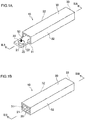
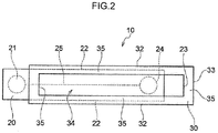
- Fig. 1A and Fig. 1B , Fig. 2 , and Fig. 3A and Fig. 3B illustrate an analysis chip 10 according to an exemplary embodiment of the present invention.
- the analysis chip 10 of the present exemplary embodiment comprises a microchip as a first unit 20 and a cartridge as a second unit 30.
- Fig. 1A is a perspective view illustrating the analysis chip 10 in a first state in which the first unit 20 projects out from the second unit 30.
- Fig. 1B is a perspective view illustrating the analysis chip 10 in a second state in which the first unit 20 is contained within the second unit 30.
- Fig. 2 is a bottom view of the analysis chip 10.
- Fig. 3A illustrates the analysis chip 10 in the first state in which the first unit 20 projects out from the second unit 30, as seen in a cross-section taken along IIIA-IIIA in Fig. 1A .
- Fig. 3B illustrates the analysis chip 10 in the second state in which the first unit 20 is contained within the second unit 30, as seen in a cross-section taken along IIIB-IIIB in Fig. 1B .
- the first unit 20 is formed as a plate-shaped microchip that has a substantially rectangular shape (see Fig. 2 ).
- a recessed portion that serves as a sample introduction portion 21 is provided at an upper face of the first unit 20.
- a liquid sample 50 is introduced into the sample introduction portion 21 (see Fig. 1A and Fig. 3A ).
- the width of the first unit 20 is set such that that two side edges 22 of the first unit 20 are capable of sliding along the inner walls of the second unit 30. Further, both the side edges 22 run parallel to the direction along which the first unit 20 moves from the first state illustrated in Fig. 1A to the second state illustrated in Fig. 1B .
- the edge of the first unit 20 at an opposite side from the side at which the sample introduction portion 21 is provided provides an abutting edge 23 (see Fig. 2 , Fig. 3A, and Fig. 3B ).
- various structures necessary for carrying out measurements are also provided, such as a discharge portion 24 to which the sample 50 is discharged, a flow path 25 serving as a capillary at which an introduced sample 50 is subject to electrophoresis from the sample introduction portion 21 to the discharge portion 24, a reaction section at which a reaction of the sample 50 with a given chemical reagent occurs at a particular position along the channel, and a detection section at which a measurement light is irradiated.
- the reaction section and detection section are omitted from the drawings.
- specimens may be employed as the sample 50.
- specimens of biological origin such as blood, urine, or sweat
- samples that are the subject of environmental surveys such as those from a water survey or a geological survey.
- the specimen is liquid, it may be employed as the sample 50 as is, or after being appropriately diluted or concentrated.
- the specimen can be employed as the sample 50 only after the specimen is dissolved or dispersed in a suitable solvent so as to be in a liquid state.
- the second unit 30 is formed in a substantially cuboidal box shape that has its length direction aligned with the length direction of the first unit 20.
- the bottom face of the second unit 30 comprises a measurement port 34 that is an opening, for example a rectangular-shaped opening.
- An edge portion of the bottom face of the second unit 30 that surrounds the measurement port 34 provides a support edge 35 (see Fig. 2 ).
- One of the end faces of the second unit 30 opens so as to provide an insertion port 31 (see Fig. 1A, Fig. 1B , Fig. 3A, and Fig. 3B ), through which the first unit 20 is inserted into the second unit 30.
- the other end face of the second unit 30 is closed so as to provide a position restriction portion 33 (see Fig. 2 , Fig. 3A, and Fig. 3B ).
- the abutting edge 23 of the first unit 20 contacts an inner side of the position restriction portion 33 (see Fig. 3B ).
- two side faces of the second unit 30 serve as guide portions 32.
- the inner sides of the guide portions 32 contact the respective side edges 22 of the first unit 20 (see Fig. 2 ).
- the sample introduction portion 21 of the first unit 20 is positioned outside the second unit 30 relative to the open insertion port 31 of the second unit 30.
- at least a portion of the first unit 20 at which the sample introduction portion 21 is located is positioned so as to project out from the insertion port 31 of the second unit 30.
- a liquid sample 50 is introduced into the sample introduction portion 21 by being dropped thereon or directly contacted thereto.
- the first unit 20 When the first unit 20 is pressed into the second unit 30 from the first state, the first unit 20 moves into the second unit 30 as both the side edges 22 of the first unit 20 slide along the guide portions 32 of the second unit 30. Then, the second state illustrated in Fig. 1B and Fig. 3B is achieved when the abutting edge 23 of the first unit 20 abuts the position restriction portion 33 of the second unit 30. Namely, in the second state, the sample introduction portion 21 of the first unit 20 is positioned inside the second unit 30 relative to the insertion port 31 of the second unit 30.
- the guide portions 32 of the second unit 30 are provided at positions along which both the side edges 22 of the first unit 20 are slidable, thus guiding the direction of movement between the first state and the second state.
- the guide portions 32 of the second unit 30 guide the first unit 20 from the first state to the second state.
- the position restriction portion 33 of the second unit 30 limits further movement of the first unit 20, thereby holding the first unit 20 in the second state.
- the first unit 20 is supported in a state mounted on the support edge 35 of the bottom face of the second unit 30.
- the analysis chip 10 is set in an analysis instrument (not illustrated) and predetermined measurements are performed.
- a predetermined operation such as radiation of measurement light or the like, is performed through the measurement port 34 in the bottom face of the second unit 30.
- the analysis chip 10 is preferably formed as a disposable unit in which all of, or almost all of, both of the first unit 20 as a microchip and the second unit 30 as a cartridge housing the first unit 30 is molded from a synthetic resin.
- a structure may be provided for keeping the analysis chip 10 in the second state.
- the first unit 20 may comprise a member to close the insertion port 31 during the second state.
- structures that mutually engage in the second state may be provided between both the side edges 22 of the first unit 20 and the guide portions 32 of the second unit 30 (for example, recesses on both the side edges 22 and projections on the guide portions 32).
- the present invention may be employed for an analysis chip that includes a microchip employed for capillary electrophoresis.
Landscapes
- Health & Medical Sciences (AREA)
- Chemical & Material Sciences (AREA)
- Life Sciences & Earth Sciences (AREA)
- Molecular Biology (AREA)
- Analytical Chemistry (AREA)
- Chemical Kinetics & Catalysis (AREA)
- General Health & Medical Sciences (AREA)
- Electrochemistry (AREA)
- Physics & Mathematics (AREA)
- Biochemistry (AREA)
- General Physics & Mathematics (AREA)
- Immunology (AREA)
- Pathology (AREA)
- Dispersion Chemistry (AREA)
- Hematology (AREA)
- Clinical Laboratory Science (AREA)
- Automatic Analysis And Handling Materials Therefor (AREA)
Abstract
Description
- The present invention relates to an analysis chip that may include a microchip employed for capillary electrophoresis.
- Conventionally, specimen analysis techniques have been performed by capillary electrophoresis. In recent years, microchip electrophoresis, which employs capillaries adapted for chip devices, has been performed, in order to miniaturize and to simplify such devices. In microchip electrophoresis, capillaries used for electrophoresis and reservoir wells for various types of solutions are formed on a single chip.
- An example of such a microchip is described in
JP 1999-337521 A WO 2008/136465 A1 , the microchip disclosed therein comprising only a single capillary and solution reservoir wells at both ends of the capillary. Further, a microchip provided with film-shaped electrodes is described inJP 4178653 B - Furthermore,
JP 2016-212090 A - In the aforementioned
JP 2016-212090 A - According to a first aspect, the present invention provides an analysis chip that includes a microchip employed for capillary electrophoresis and a cartridge. The analysis chip is structured so as to enable the microchip and the cartridge to be reliably coupled together and such that the microchip is able to be reliably housed in the cartridge.
- According to a second aspect of the present invention, there is provided an analysis chip which can be employed to analyze a sample, and which comprises a first unit that comprises a sample introduction portion into which the sample is introduced, and a second unit that is configured to house the first unit. The second unit comprises an insertion port into which the first unit is inserted. The first unit is formed so as to be moveable from a first state in which the sample introduction portion is positioned outside the second unit relative to the insertion port, to a second state in which the sample introduction portion is positioned inside the second unit relative to the insertion port. The second unit comprises a guide portion that guides the first unit from the first state to the second state.
- In a preferred embodiment of the present invention, the first unit has two side edges running parallel to a direction of movement from the first state to the second state, and the guide portion is provided at a position along which both the side edges are slidable in the direction of movement.
- In another preferred embodiment of the present invention, the second unit comprises a position restriction portion that holds the first unit in the second state.
- In embodiments of the present invention, an analysis chip can be provided that includes a microchip employed for capillary electrophoresis (the "first unit") and a cartridge (the "second unit"). The analysis chip has a structure in which the microchip and the cartridge can be reliably coupled together, and the microchip can be reliably housed in the cartridge.
- Exemplary embodiments will be described in detail based on the following figures, wherein:
-
Fig. 1A is a perspective view illustrating an analysis chip according to an exemplary embodiment of the present invention in a first state, andFig. 1B illustrates the analysis chip in a second state; -
Fig. 2 is a bottom view illustrating an analysis chip according to an exemplary embodiment of the present invention; and -
Fig. 3A is a cross-section taken along IIIA-IIIA inFig. 1A , andFig. 3B is a cross-section taken along IIIB-IIIB inFig. 1B . - Explanation follows regarding a preferred embodiment of the present invention, with reference to the drawings. Note that the following description and the drawings merely show an exemplary embodiment of the present invention, and the present invention is not limited thereto.
-
Fig. 1A and Fig. 1B ,Fig. 2 , andFig. 3A and Fig. 3B illustrate ananalysis chip 10 according to an exemplary embodiment of the present invention. Theanalysis chip 10 of the present exemplary embodiment comprises a microchip as afirst unit 20 and a cartridge as asecond unit 30. -
Fig. 1A is a perspective view illustrating theanalysis chip 10 in a first state in which thefirst unit 20 projects out from thesecond unit 30.Fig. 1B is a perspective view illustrating theanalysis chip 10 in a second state in which thefirst unit 20 is contained within thesecond unit 30.Fig. 2 is a bottom view of theanalysis chip 10.Fig. 3A illustrates theanalysis chip 10 in the first state in which thefirst unit 20 projects out from thesecond unit 30, as seen in a cross-section taken along IIIA-IIIA inFig. 1A .Fig. 3B illustrates theanalysis chip 10 in the second state in which thefirst unit 20 is contained within thesecond unit 30, as seen in a cross-section taken along IIIB-IIIB inFig. 1B . - The
first unit 20 is formed as a plate-shaped microchip that has a substantially rectangular shape (seeFig. 2 ). A recessed portion that serves as asample introduction portion 21 is provided at an upper face of thefirst unit 20. Aliquid sample 50 is introduced into the sample introduction portion 21 (seeFig. 1A andFig. 3A ). Moreover, the width of thefirst unit 20 is set such that that twoside edges 22 of thefirst unit 20 are capable of sliding along the inner walls of thesecond unit 30. Further, both theside edges 22 run parallel to the direction along which thefirst unit 20 moves from the first state illustrated inFig. 1A to the second state illustrated inFig. 1B . Further, the edge of thefirst unit 20 at an opposite side from the side at which thesample introduction portion 21 is provided provides an abutting edge 23 (seeFig. 2 ,Fig. 3A, and Fig. 3B ). At some locations of thefirst unit 20, various structures necessary for carrying out measurements are also provided, such as adischarge portion 24 to which thesample 50 is discharged, aflow path 25 serving as a capillary at which an introducedsample 50 is subject to electrophoresis from thesample introduction portion 21 to thedischarge portion 24, a reaction section at which a reaction of thesample 50 with a given chemical reagent occurs at a particular position along the channel, and a detection section at which a measurement light is irradiated. The reaction section and detection section are omitted from the drawings. - A wide variety of specimens may be employed as the
sample 50. Examples thereof include specimens of biological origin such as blood, urine, or sweat, and samples that are the subject of environmental surveys, such as those from a water survey or a geological survey. If the specimen is liquid, it may be employed as thesample 50 as is, or after being appropriately diluted or concentrated. Further, in cases in which the specimen is solid, or a highly viscous liquid or a gel, the specimen can be employed as thesample 50 only after the specimen is dissolved or dispersed in a suitable solvent so as to be in a liquid state. - The
second unit 30 is formed in a substantially cuboidal box shape that has its length direction aligned with the length direction of thefirst unit 20. The bottom face of thesecond unit 30 comprises ameasurement port 34 that is an opening, for example a rectangular-shaped opening. An edge portion of the bottom face of thesecond unit 30 that surrounds themeasurement port 34 provides a support edge 35 (seeFig. 2 ). - One of the end faces of the
second unit 30 opens so as to provide an insertion port 31 (seeFig. 1A, Fig. 1B ,Fig. 3A, and Fig. 3B ), through which thefirst unit 20 is inserted into thesecond unit 30. Moreover, the other end face of thesecond unit 30 is closed so as to provide a position restriction portion 33 (seeFig. 2 ,Fig. 3A, and Fig. 3B ). In the second state, the abuttingedge 23 of thefirst unit 20 contacts an inner side of the position restriction portion 33 (seeFig. 3B ). Further, two side faces of thesecond unit 30 serve asguide portions 32. The inner sides of theguide portions 32 contact the respective side edges 22 of the first unit 20 (seeFig. 2 ). - Explanation follows regarding functions of the present exemplary embodiment.
- In the first state illustrated in
Fig. 1A andFig. 3A , thesample introduction portion 21 of thefirst unit 20 is positioned outside thesecond unit 30 relative to theopen insertion port 31 of thesecond unit 30. In other words, at least a portion of thefirst unit 20 at which thesample introduction portion 21 is located is positioned so as to project out from theinsertion port 31 of thesecond unit 30. In this state, aliquid sample 50 is introduced into thesample introduction portion 21 by being dropped thereon or directly contacted thereto. - When the
first unit 20 is pressed into thesecond unit 30 from the first state, thefirst unit 20 moves into thesecond unit 30 as both the side edges 22 of thefirst unit 20 slide along theguide portions 32 of thesecond unit 30. Then, the second state illustrated inFig. 1B andFig. 3B is achieved when the abuttingedge 23 of thefirst unit 20 abuts theposition restriction portion 33 of thesecond unit 30. Namely, in the second state, thesample introduction portion 21 of thefirst unit 20 is positioned inside thesecond unit 30 relative to theinsertion port 31 of thesecond unit 30. - Namely, the
guide portions 32 of thesecond unit 30 are provided at positions along which both the side edges 22 of thefirst unit 20 are slidable, thus guiding the direction of movement between the first state and the second state. In other words, theguide portions 32 of thesecond unit 30 guide thefirst unit 20 from the first state to the second state. Further, theposition restriction portion 33 of thesecond unit 30 limits further movement of thefirst unit 20, thereby holding thefirst unit 20 in the second state. - Further, throughout the movement from the first state to the second state shown above, the
first unit 20 is supported in a state mounted on thesupport edge 35 of the bottom face of thesecond unit 30. - Then, in the second state, the
analysis chip 10 is set in an analysis instrument (not illustrated) and predetermined measurements are performed. At this time, a predetermined operation, such as radiation of measurement light or the like, is performed through themeasurement port 34 in the bottom face of thesecond unit 30. - The
analysis chip 10 is preferably formed as a disposable unit in which all of, or almost all of, both of thefirst unit 20 as a microchip and thesecond unit 30 as a cartridge housing thefirst unit 30 is molded from a synthetic resin. - Moreover, in another exemplary embodiment, a structure may be provided for keeping the
analysis chip 10 in the second state. For example, thefirst unit 20 may comprise a member to close theinsertion port 31 during the second state. Further, structures that mutually engage in the second state may be provided between both the side edges 22 of thefirst unit 20 and theguide portions 32 of the second unit 30 (for example, recesses on both the side edges 22 and projections on the guide portions 32). - The present invention may be employed for an analysis chip that includes a microchip employed for capillary electrophoresis.
Claims (7)
- An analysis chip (10) for being employed in the analysis of a sample (50), the analysis chip (10) comprising:a first unit (20) that comprises a sample introduction portion (21) into which the sample (50) can be introduced; anda second unit (30) that is configured to house the first unit (20),the second unit (30) comprising an insertion port (31) into which the first unit (20) can be inserted,the first unit (20) being formed so as to be moveable from a first state in which the sample introduction portion (21) is positioned outside the second unit (30), to a second state in which the sample introduction portion (21) is positioned inside the second unit (30), andthe second unit (30) comprising a guide portion (32) for guiding the first unit (20) from the first state to the second state.
- The analysis chip of claim 1, wherein:the first unit (20) has two side edges (22) running parallel to a direction of movement from the first state to the second state; andthe guide portion (32) is provided at a position along which both the side edges (22) are slidable in the direction of movement.
- The analysis chip of claim 1 or claim 2, wherein the second unit (30) comprises a position restriction portion (33) for holding the first unit (20) in the second state.
- The analysis chip of any preceding claim, wherein the second unit (30) comprises a measurement port (34) in a bottom face of the second unit (30).
- The analysis chip of claim 4, wherein an edge portion of the bottom face of the second unit (30) that surrounds the measurement port (34) provides a support edge (35) onto which the first unit (20) can be mounted.
- The analysis chip of any preceding claim, wherein the first unit (20) is a microchip to be employed for capillary electrophoresis and the second unit (30) is a cartridge configured to house the microchip (20).
- The analysis chip of claim 6, wherein the microchip (20) comprises a sample introduction portion (21) into which the sample (50) can be introduced, a discharge portion (24) to which the sample (50) can be discharged, and a flow path (25) serving as a capillary within which the sample (50) can be subject to electrophoresis from the sample introduction portion (21) to the discharge portion (24).
Applications Claiming Priority (1)
| Application Number | Priority Date | Filing Date | Title |
|---|---|---|---|
| JP2017150736A JP2019028021A (en) | 2017-08-03 | 2017-08-03 | Analytical device |
Publications (3)
| Publication Number | Publication Date |
|---|---|
| EP3438654A2 true EP3438654A2 (en) | 2019-02-06 |
| EP3438654A3 EP3438654A3 (en) | 2019-03-06 |
| EP3438654B1 EP3438654B1 (en) | 2022-09-14 |
Family
ID=63077695
Family Applications (1)
| Application Number | Title | Priority Date | Filing Date |
|---|---|---|---|
| EP18185604.8A Active EP3438654B1 (en) | 2017-08-03 | 2018-07-25 | Analysis chip |
Country Status (4)
| Country | Link |
|---|---|
| US (1) | US20190041358A1 (en) |
| EP (1) | EP3438654B1 (en) |
| JP (1) | JP2019028021A (en) |
| CN (1) | CN109387557A (en) |
Families Citing this family (2)
| Publication number | Priority date | Publication date | Assignee | Title |
|---|---|---|---|---|
| JP6756386B2 (en) * | 2019-02-20 | 2020-09-16 | 株式会社三洋物産 | Game machine |
| CN117890452B (en) * | 2024-03-18 | 2024-06-25 | 深圳市真迈生物科技有限公司 | Chip transfer device, equipment and analysis system |
Citations (4)
| Publication number | Priority date | Publication date | Assignee | Title |
|---|---|---|---|---|
| JPH11337521A (en) | 1998-05-22 | 1999-12-10 | Shimadzu Corp | Electrophoresis components |
| JP4178653B2 (en) | 1999-02-26 | 2008-11-12 | 日立化成工業株式会社 | Electrophoresis chip and method for producing the same, electrophoresis apparatus using the electrophoresis chip, and method for separating charged substance |
| WO2008136465A1 (en) | 2007-04-27 | 2008-11-13 | National Institute Of Advanced Industrial Science And Technology | Electrophoresis chip, electrophoresis device, and sample analyzing method by capillary electrophoresis method |
| JP2016212090A (en) | 2015-05-13 | 2016-12-15 | アークレイ株式会社 | Analysis tool and analysis system |
Family Cites Families (14)
| Publication number | Priority date | Publication date | Assignee | Title |
|---|---|---|---|---|
| JP2000074880A (en) * | 1998-08-28 | 2000-03-14 | Shimadzu Corp | Microchip sample introduction method |
| JP4085514B2 (en) * | 1999-04-30 | 2008-05-14 | 株式会社島津製作所 | Electrophoresis chip |
| ITRM20020244A1 (en) * | 2002-05-06 | 2003-11-06 | Idiogenes S P A | INTEGRATED DEVICE FOR THE PERFORMANCE OF A GENETIC INVESTIGATION AND RELATED EXAMINATION AND READING EQUIPMENT. |
| US7244961B2 (en) * | 2002-08-02 | 2007-07-17 | Silicon Valley Scientific | Integrated system with modular microfluidic components |
| US20040086872A1 (en) * | 2002-10-31 | 2004-05-06 | Childers Winthrop D. | Microfluidic system for analysis of nucleic acids |
| JP2005106788A (en) * | 2003-10-02 | 2005-04-21 | Kobe Steel Ltd | Microchip for electrophoresis |
| US8394341B2 (en) * | 2004-03-08 | 2013-03-12 | Agilent Technologies, Inc. | Microfluidic chip frame |
| CN101006344B (en) * | 2004-05-21 | 2011-07-13 | 卡钳生命科学股份有限公司 | Automat system for handling microfluidic devices |
| JP4448457B2 (en) * | 2005-02-01 | 2010-04-07 | 公立大学法人公立はこだて未来大学 | Sensory substitution device |
| JP2006337214A (en) * | 2005-06-02 | 2006-12-14 | Matsushita Electric Ind Co Ltd | Biological sample discrimination device, biological sample discrimination plate cartridge, and biological sample discrimination plate supply device |
| JP5266208B2 (en) * | 2006-05-09 | 2013-08-21 | アドヴァンスト リキッド ロジック インコーポレイテッド | Droplet treatment system |
| US9007075B2 (en) * | 2008-08-07 | 2015-04-14 | Agency For Science, Technology And Research | Contactless conductivity detector |
| JP2012068214A (en) * | 2010-09-27 | 2012-04-05 | Arkray Inc | Microchip for analysis device |
| JP2012229932A (en) * | 2011-04-25 | 2012-11-22 | Shimadzu Corp | Microchip electrophoretic apparatus |
-
2017
- 2017-08-03 JP JP2017150736A patent/JP2019028021A/en active Pending
-
2018
- 2018-07-25 EP EP18185604.8A patent/EP3438654B1/en active Active
- 2018-07-30 US US16/049,035 patent/US20190041358A1/en not_active Abandoned
- 2018-08-01 CN CN201810869811.3A patent/CN109387557A/en active Pending
Patent Citations (4)
| Publication number | Priority date | Publication date | Assignee | Title |
|---|---|---|---|---|
| JPH11337521A (en) | 1998-05-22 | 1999-12-10 | Shimadzu Corp | Electrophoresis components |
| JP4178653B2 (en) | 1999-02-26 | 2008-11-12 | 日立化成工業株式会社 | Electrophoresis chip and method for producing the same, electrophoresis apparatus using the electrophoresis chip, and method for separating charged substance |
| WO2008136465A1 (en) | 2007-04-27 | 2008-11-13 | National Institute Of Advanced Industrial Science And Technology | Electrophoresis chip, electrophoresis device, and sample analyzing method by capillary electrophoresis method |
| JP2016212090A (en) | 2015-05-13 | 2016-12-15 | アークレイ株式会社 | Analysis tool and analysis system |
Also Published As
| Publication number | Publication date |
|---|---|
| JP2019028021A (en) | 2019-02-21 |
| EP3438654B1 (en) | 2022-09-14 |
| US20190041358A1 (en) | 2019-02-07 |
| CN109387557A (en) | 2019-02-26 |
| EP3438654A3 (en) | 2019-03-06 |
Similar Documents
| Publication | Publication Date | Title |
|---|---|---|
| US12207925B2 (en) | Mobile lab-on-a-chip diagnostic system | |
| AU2013322362B2 (en) | Test device and sample carrier | |
| US8440148B2 (en) | Microfluidic device and microfluidic analysis equipment | |
| US9726680B2 (en) | Reaction vessel, assay device, and measuring method | |
| US11644476B2 (en) | Analysis device | |
| EP3438654B1 (en) | Analysis chip | |
| US11619644B2 (en) | Analysis device and positioning method | |
| KR20140041469A (en) | Test meter with a strip port connector configured for fluid entrapment | |
| EP3567360A1 (en) | Device for dividing sample-capture chip | |
| EP2957343B1 (en) | Fluid handling device | |
| CN113649098A (en) | Microfluidic detection assembly, sample mixing device and application thereof | |
| EP4039359A1 (en) | Microchannel chip | |
| US11415586B2 (en) | Analysis device | |
| CN111511472B (en) | Equipment for sample analysis | |
| JP4206370B2 (en) | Positioning device for inspection elements | |
| KR101894100B1 (en) | Bio sensor | |
| WO2020004590A1 (en) | Sample collection device and sample preparation device | |
| US11040348B2 (en) | Biological sample analysis kit and sample collection unit with a cap having an access opening | |
| JP5487466B2 (en) | Analytical device | |
| JP4726135B2 (en) | Fluid handling equipment | |
| US11327006B2 (en) | Analysis device | |
| CN117491101A (en) | Sample adding components and sample processing devices | |
| OA17371A (en) | Test device and sample Carrier. | |
| GB2500892A (en) | Cartridge for test apparatus with a latch | |
| KR20140046149A (en) | Structure of delaying time and micro device having the same structure for delaying time and methods of moving sample using micro device |
Legal Events
| Date | Code | Title | Description |
|---|---|---|---|
| PUAI | Public reference made under article 153(3) epc to a published international application that has entered the european phase |
Free format text: ORIGINAL CODE: 0009012 |
|
| STAA | Information on the status of an ep patent application or granted ep patent |
Free format text: STATUS: THE APPLICATION HAS BEEN PUBLISHED |
|
| PUAL | Search report despatched |
Free format text: ORIGINAL CODE: 0009013 |
|
| AK | Designated contracting states |
Kind code of ref document: A2 Designated state(s): AL AT BE BG CH CY CZ DE DK EE ES FI FR GB GR HR HU IE IS IT LI LT LU LV MC MK MT NL NO PL PT RO RS SE SI SK SM TR |
|
| AX | Request for extension of the european patent |
Extension state: BA ME |
|
| AK | Designated contracting states |
Kind code of ref document: A3 Designated state(s): AL AT BE BG CH CY CZ DE DK EE ES FI FR GB GR HR HU IE IS IT LI LT LU LV MC MK MT NL NO PL PT RO RS SE SI SK SM TR |
|
| AX | Request for extension of the european patent |
Extension state: BA ME |
|
| RIC1 | Information provided on ipc code assigned before grant |
Ipc: G01N 27/447 20060101AFI20190125BHEP Ipc: B01L 3/00 20060101ALI20190125BHEP |
|
| STAA | Information on the status of an ep patent application or granted ep patent |
Free format text: STATUS: REQUEST FOR EXAMINATION WAS MADE |
|
| 17P | Request for examination filed |
Effective date: 20190904 |
|
| RBV | Designated contracting states (corrected) |
Designated state(s): AL AT BE BG CH CY CZ DE DK EE ES FI FR GB GR HR HU IE IS IT LI LT LU LV MC MK MT NL NO PL PT RO RS SE SI SK SM TR |
|
| GRAP | Despatch of communication of intention to grant a patent |
Free format text: ORIGINAL CODE: EPIDOSNIGR1 |
|
| STAA | Information on the status of an ep patent application or granted ep patent |
Free format text: STATUS: GRANT OF PATENT IS INTENDED |
|
| INTG | Intention to grant announced |
Effective date: 20220530 |
|
| GRAS | Grant fee paid |
Free format text: ORIGINAL CODE: EPIDOSNIGR3 |
|
| GRAA | (expected) grant |
Free format text: ORIGINAL CODE: 0009210 |
|
| STAA | Information on the status of an ep patent application or granted ep patent |
Free format text: STATUS: THE PATENT HAS BEEN GRANTED |
|
| AK | Designated contracting states |
Kind code of ref document: B1 Designated state(s): AL AT BE BG CH CY CZ DE DK EE ES FI FR GB GR HR HU IE IS IT LI LT LU LV MC MK MT NL NO PL PT RO RS SE SI SK SM TR |
|
| REG | Reference to a national code |
Ref country code: GB Ref legal event code: FG4D |
|
| REG | Reference to a national code |
Ref country code: CH Ref legal event code: EP |
|
| REG | Reference to a national code |
Ref country code: DE Ref legal event code: R096 Ref document number: 602018040580 Country of ref document: DE |
|
| REG | Reference to a national code |
Ref country code: IE Ref legal event code: FG4D |
|
| REG | Reference to a national code |
Ref country code: AT Ref legal event code: REF Ref document number: 1518998 Country of ref document: AT Kind code of ref document: T Effective date: 20221015 |
|
| REG | Reference to a national code |
Ref country code: LT Ref legal event code: MG9D |
|
| REG | Reference to a national code |
Ref country code: NL Ref legal event code: MP Effective date: 20220914 |
|
| PG25 | Lapsed in a contracting state [announced via postgrant information from national office to epo] |
Ref country code: SE Free format text: LAPSE BECAUSE OF FAILURE TO SUBMIT A TRANSLATION OF THE DESCRIPTION OR TO PAY THE FEE WITHIN THE PRESCRIBED TIME-LIMIT Effective date: 20220914 Ref country code: RS Free format text: LAPSE BECAUSE OF FAILURE TO SUBMIT A TRANSLATION OF THE DESCRIPTION OR TO PAY THE FEE WITHIN THE PRESCRIBED TIME-LIMIT Effective date: 20220914 Ref country code: NO Free format text: LAPSE BECAUSE OF FAILURE TO SUBMIT A TRANSLATION OF THE DESCRIPTION OR TO PAY THE FEE WITHIN THE PRESCRIBED TIME-LIMIT Effective date: 20221214 Ref country code: LV Free format text: LAPSE BECAUSE OF FAILURE TO SUBMIT A TRANSLATION OF THE DESCRIPTION OR TO PAY THE FEE WITHIN THE PRESCRIBED TIME-LIMIT Effective date: 20220914 Ref country code: LT Free format text: LAPSE BECAUSE OF FAILURE TO SUBMIT A TRANSLATION OF THE DESCRIPTION OR TO PAY THE FEE WITHIN THE PRESCRIBED TIME-LIMIT Effective date: 20220914 Ref country code: FI Free format text: LAPSE BECAUSE OF FAILURE TO SUBMIT A TRANSLATION OF THE DESCRIPTION OR TO PAY THE FEE WITHIN THE PRESCRIBED TIME-LIMIT Effective date: 20220914 |
|
| REG | Reference to a national code |
Ref country code: AT Ref legal event code: MK05 Ref document number: 1518998 Country of ref document: AT Kind code of ref document: T Effective date: 20220914 |
|
| PG25 | Lapsed in a contracting state [announced via postgrant information from national office to epo] |
Ref country code: HR Free format text: LAPSE BECAUSE OF FAILURE TO SUBMIT A TRANSLATION OF THE DESCRIPTION OR TO PAY THE FEE WITHIN THE PRESCRIBED TIME-LIMIT Effective date: 20220914 Ref country code: GR Free format text: LAPSE BECAUSE OF FAILURE TO SUBMIT A TRANSLATION OF THE DESCRIPTION OR TO PAY THE FEE WITHIN THE PRESCRIBED TIME-LIMIT Effective date: 20221215 |
|
| PG25 | Lapsed in a contracting state [announced via postgrant information from national office to epo] |
Ref country code: SM Free format text: LAPSE BECAUSE OF FAILURE TO SUBMIT A TRANSLATION OF THE DESCRIPTION OR TO PAY THE FEE WITHIN THE PRESCRIBED TIME-LIMIT Effective date: 20220914 Ref country code: RO Free format text: LAPSE BECAUSE OF FAILURE TO SUBMIT A TRANSLATION OF THE DESCRIPTION OR TO PAY THE FEE WITHIN THE PRESCRIBED TIME-LIMIT Effective date: 20220914 Ref country code: PT Free format text: LAPSE BECAUSE OF FAILURE TO SUBMIT A TRANSLATION OF THE DESCRIPTION OR TO PAY THE FEE WITHIN THE PRESCRIBED TIME-LIMIT Effective date: 20230116 Ref country code: ES Free format text: LAPSE BECAUSE OF FAILURE TO SUBMIT A TRANSLATION OF THE DESCRIPTION OR TO PAY THE FEE WITHIN THE PRESCRIBED TIME-LIMIT Effective date: 20220914 Ref country code: CZ Free format text: LAPSE BECAUSE OF FAILURE TO SUBMIT A TRANSLATION OF THE DESCRIPTION OR TO PAY THE FEE WITHIN THE PRESCRIBED TIME-LIMIT Effective date: 20220914 Ref country code: AT Free format text: LAPSE BECAUSE OF FAILURE TO SUBMIT A TRANSLATION OF THE DESCRIPTION OR TO PAY THE FEE WITHIN THE PRESCRIBED TIME-LIMIT Effective date: 20220914 |
|
| PG25 | Lapsed in a contracting state [announced via postgrant information from national office to epo] |
Ref country code: SK Free format text: LAPSE BECAUSE OF FAILURE TO SUBMIT A TRANSLATION OF THE DESCRIPTION OR TO PAY THE FEE WITHIN THE PRESCRIBED TIME-LIMIT Effective date: 20220914 Ref country code: PL Free format text: LAPSE BECAUSE OF FAILURE TO SUBMIT A TRANSLATION OF THE DESCRIPTION OR TO PAY THE FEE WITHIN THE PRESCRIBED TIME-LIMIT Effective date: 20220914 Ref country code: IS Free format text: LAPSE BECAUSE OF FAILURE TO SUBMIT A TRANSLATION OF THE DESCRIPTION OR TO PAY THE FEE WITHIN THE PRESCRIBED TIME-LIMIT Effective date: 20230114 Ref country code: EE Free format text: LAPSE BECAUSE OF FAILURE TO SUBMIT A TRANSLATION OF THE DESCRIPTION OR TO PAY THE FEE WITHIN THE PRESCRIBED TIME-LIMIT Effective date: 20220914 |
|
| REG | Reference to a national code |
Ref country code: DE Ref legal event code: R097 Ref document number: 602018040580 Country of ref document: DE |
|
| PG25 | Lapsed in a contracting state [announced via postgrant information from national office to epo] |
Ref country code: NL Free format text: LAPSE BECAUSE OF FAILURE TO SUBMIT A TRANSLATION OF THE DESCRIPTION OR TO PAY THE FEE WITHIN THE PRESCRIBED TIME-LIMIT Effective date: 20220914 Ref country code: AL Free format text: LAPSE BECAUSE OF FAILURE TO SUBMIT A TRANSLATION OF THE DESCRIPTION OR TO PAY THE FEE WITHIN THE PRESCRIBED TIME-LIMIT Effective date: 20220914 |
|
| PLBE | No opposition filed within time limit |
Free format text: ORIGINAL CODE: 0009261 |
|
| STAA | Information on the status of an ep patent application or granted ep patent |
Free format text: STATUS: NO OPPOSITION FILED WITHIN TIME LIMIT |
|
| PG25 | Lapsed in a contracting state [announced via postgrant information from national office to epo] |
Ref country code: DK Free format text: LAPSE BECAUSE OF FAILURE TO SUBMIT A TRANSLATION OF THE DESCRIPTION OR TO PAY THE FEE WITHIN THE PRESCRIBED TIME-LIMIT Effective date: 20220914 |
|
| 26N | No opposition filed |
Effective date: 20230615 |
|
| PG25 | Lapsed in a contracting state [announced via postgrant information from national office to epo] |
Ref country code: SI Free format text: LAPSE BECAUSE OF FAILURE TO SUBMIT A TRANSLATION OF THE DESCRIPTION OR TO PAY THE FEE WITHIN THE PRESCRIBED TIME-LIMIT Effective date: 20220914 |
|
| PG25 | Lapsed in a contracting state [announced via postgrant information from national office to epo] |
Ref country code: MC Free format text: LAPSE BECAUSE OF FAILURE TO SUBMIT A TRANSLATION OF THE DESCRIPTION OR TO PAY THE FEE WITHIN THE PRESCRIBED TIME-LIMIT Effective date: 20220914 |
|
| PG25 | Lapsed in a contracting state [announced via postgrant information from national office to epo] |
Ref country code: MC Free format text: LAPSE BECAUSE OF FAILURE TO SUBMIT A TRANSLATION OF THE DESCRIPTION OR TO PAY THE FEE WITHIN THE PRESCRIBED TIME-LIMIT Effective date: 20220914 |
|
| REG | Reference to a national code |
Ref country code: CH Ref legal event code: PL |
|
| REG | Reference to a national code |
Ref country code: BE Ref legal event code: MM Effective date: 20230731 |
|
| PG25 | Lapsed in a contracting state [announced via postgrant information from national office to epo] |
Ref country code: LU Free format text: LAPSE BECAUSE OF NON-PAYMENT OF DUE FEES Effective date: 20230725 |
|
| PG25 | Lapsed in a contracting state [announced via postgrant information from national office to epo] |
Ref country code: LU Free format text: LAPSE BECAUSE OF NON-PAYMENT OF DUE FEES Effective date: 20230725 |
|
| REG | Reference to a national code |
Ref country code: IE Ref legal event code: MM4A |
|
| PG25 | Lapsed in a contracting state [announced via postgrant information from national office to epo] |
Ref country code: CH Free format text: LAPSE BECAUSE OF NON-PAYMENT OF DUE FEES Effective date: 20230731 |
|
| PG25 | Lapsed in a contracting state [announced via postgrant information from national office to epo] |
Ref country code: BE Free format text: LAPSE BECAUSE OF NON-PAYMENT OF DUE FEES Effective date: 20230731 |
|
| PG25 | Lapsed in a contracting state [announced via postgrant information from national office to epo] |
Ref country code: IE Free format text: LAPSE BECAUSE OF NON-PAYMENT OF DUE FEES Effective date: 20230725 |
|
| PG25 | Lapsed in a contracting state [announced via postgrant information from national office to epo] |
Ref country code: IE Free format text: LAPSE BECAUSE OF NON-PAYMENT OF DUE FEES Effective date: 20230725 |
|
| PG25 | Lapsed in a contracting state [announced via postgrant information from national office to epo] |
Ref country code: BG Free format text: LAPSE BECAUSE OF FAILURE TO SUBMIT A TRANSLATION OF THE DESCRIPTION OR TO PAY THE FEE WITHIN THE PRESCRIBED TIME-LIMIT Effective date: 20220914 |
|
| PG25 | Lapsed in a contracting state [announced via postgrant information from national office to epo] |
Ref country code: BG Free format text: LAPSE BECAUSE OF FAILURE TO SUBMIT A TRANSLATION OF THE DESCRIPTION OR TO PAY THE FEE WITHIN THE PRESCRIBED TIME-LIMIT Effective date: 20220914 |
|
| PG25 | Lapsed in a contracting state [announced via postgrant information from national office to epo] |
Ref country code: CY Free format text: LAPSE BECAUSE OF FAILURE TO SUBMIT A TRANSLATION OF THE DESCRIPTION OR TO PAY THE FEE WITHIN THE PRESCRIBED TIME-LIMIT; INVALID AB INITIO Effective date: 20180725 |
|
| PG25 | Lapsed in a contracting state [announced via postgrant information from national office to epo] |
Ref country code: HU Free format text: LAPSE BECAUSE OF FAILURE TO SUBMIT A TRANSLATION OF THE DESCRIPTION OR TO PAY THE FEE WITHIN THE PRESCRIBED TIME-LIMIT; INVALID AB INITIO Effective date: 20180725 |
|
| PGFP | Annual fee paid to national office [announced via postgrant information from national office to epo] |
Ref country code: DE Payment date: 20250722 Year of fee payment: 8 |
|
| PGFP | Annual fee paid to national office [announced via postgrant information from national office to epo] |
Ref country code: IT Payment date: 20250724 Year of fee payment: 8 |
|
| PGFP | Annual fee paid to national office [announced via postgrant information from national office to epo] |
Ref country code: GB Payment date: 20250722 Year of fee payment: 8 |
|
| PGFP | Annual fee paid to national office [announced via postgrant information from national office to epo] |
Ref country code: FR Payment date: 20250725 Year of fee payment: 8 |
|
| PG25 | Lapsed in a contracting state [announced via postgrant information from national office to epo] |
Ref country code: TR Free format text: LAPSE BECAUSE OF FAILURE TO SUBMIT A TRANSLATION OF THE DESCRIPTION OR TO PAY THE FEE WITHIN THE PRESCRIBED TIME-LIMIT Effective date: 20220914 |