EP3438508A1 - Transmission case structure for saddle-type vehicle power unit - Google Patents
Transmission case structure for saddle-type vehicle power unit Download PDFInfo
- Publication number
- EP3438508A1 EP3438508A1 EP16896826.1A EP16896826A EP3438508A1 EP 3438508 A1 EP3438508 A1 EP 3438508A1 EP 16896826 A EP16896826 A EP 16896826A EP 3438508 A1 EP3438508 A1 EP 3438508A1
- Authority
- EP
- European Patent Office
- Prior art keywords
- peripheral wall
- main body
- transmission case
- axis line
- cover
- Prior art date
- Legal status (The legal status is an assumption and is not a legal conclusion. Google has not performed a legal analysis and makes no representation as to the accuracy of the status listed.)
- Granted
Links
Images




Classifications
-
- F—MECHANICAL ENGINEERING; LIGHTING; HEATING; WEAPONS; BLASTING
- F16—ENGINEERING ELEMENTS AND UNITS; GENERAL MEASURES FOR PRODUCING AND MAINTAINING EFFECTIVE FUNCTIONING OF MACHINES OR INSTALLATIONS; THERMAL INSULATION IN GENERAL
- F16H—GEARING
- F16H57/00—General details of gearing
- F16H57/02—Gearboxes; Mounting gearing therein
- F16H57/035—Gearboxes for gearing with endless flexible members
-
- F—MECHANICAL ENGINEERING; LIGHTING; HEATING; WEAPONS; BLASTING
- F16—ENGINEERING ELEMENTS AND UNITS; GENERAL MEASURES FOR PRODUCING AND MAINTAINING EFFECTIVE FUNCTIONING OF MACHINES OR INSTALLATIONS; THERMAL INSULATION IN GENERAL
- F16H—GEARING
- F16H57/00—General details of gearing
- F16H57/02—Gearboxes; Mounting gearing therein
- F16H57/031—Gearboxes; Mounting gearing therein characterised by covers or lids for gearboxes
-
- F—MECHANICAL ENGINEERING; LIGHTING; HEATING; WEAPONS; BLASTING
- F16—ENGINEERING ELEMENTS AND UNITS; GENERAL MEASURES FOR PRODUCING AND MAINTAINING EFFECTIVE FUNCTIONING OF MACHINES OR INSTALLATIONS; THERMAL INSULATION IN GENERAL
- F16H—GEARING
- F16H57/00—General details of gearing
- F16H57/02—Gearboxes; Mounting gearing therein
- F16H2057/0203—Gearboxes; Mounting gearing therein the gearbox is associated or combined with a crank case of an engine
-
- F—MECHANICAL ENGINEERING; LIGHTING; HEATING; WEAPONS; BLASTING
- F16—ENGINEERING ELEMENTS AND UNITS; GENERAL MEASURES FOR PRODUCING AND MAINTAINING EFFECTIVE FUNCTIONING OF MACHINES OR INSTALLATIONS; THERMAL INSULATION IN GENERAL
- F16H—GEARING
- F16H57/00—General details of gearing
- F16H57/02—Gearboxes; Mounting gearing therein
- F16H2057/02039—Gearboxes for particular applications
- F16H2057/02043—Gearboxes for particular applications for vehicle transmissions
- F16H2057/02065—Gearboxes for particular applications for vehicle transmissions for motorcycles or squads
Definitions
- the present invention relates to a transmission case structure for a saddle-type vehicle power unit.
- the transmission case includes a transmission case main body that extends laterally of the rear wheel from the internal combustion engine and is open at the opposite side to the rear wheel, and a transmission case that, together with the transmission case main body, forms a variable transmission chamber and is connected to the transmission case main body to close the open end of the transmission case main body.
- the variable transmission chamber is provided with a drive shaft that is rotated by a drive force of the internal combustion engine and a transmission shaft that is provided on the rear wheel side to transmit the drive force to the rear wheel, in which an endless belt is wound around a drive pulley that is attached to the drive shaft and a driven pulley that is attached to the transmission shaft.
- Patent Literature 1 Japanese Patent Laid-Open No. 2013-257010
- a belt is likely to vibrate in a direction orthogonal to an extending direction of the belt particularly, when the vehicle is accelerated or decelerated, and the belt may come into contact with an inner wall surface of the transmission case due to this vibration.
- the present invention provides a transmission case structure for a saddled vehicle power unit in which a transmission case (72) that is integrally provided to an internal combustion engine (31) and is disposed lateral to a rear wheel (13) includes a transmission case main body (34D) that extends laterally of the rear wheel (13) from the internal combustion engine (31) and is open at an opposite side to the rear wheel (13), and a transmission case cover (35) that, together with the transmission case main body (34D), forms a variable transmission chamber (86) and is connected to the transmission case main body (34D) to close an open end of the transmission case main body (34D), the transmission case main body (34D) includes a bottom portion (134f) that is located lateral to the rear wheel (13), and a first peripheral wall (134g) that extends upwardly from the bottom portion (134f) and in which a distal end portion is open, the transmission case cover (35) includes a second peripheral wall (135g) that is to be connected to the distal end portion of the first peripheral wall (
- the recesses (134s, 134t) and the recesses (135s, 135t) may be formed continuously with distal end portions of the first peripheral wall (134g) and distal end portions of the second peripheral wall (135g), respectively, and an inner peripheral surface (134r) of the first peripheral wall (134g) and an inner peripheral surface (135r) of the second peripheral wall (135g) may be connected to the recesses (134s, 134t) and the recesses (135s, 135t) through curved surfaces (134y, 134u) and curved surfaces (135y, 135u), respectively.
- the recesses (134s, 134t, 135s, 135t) may be formed at least within a range between the axis line (L1) of the drive shaft (33) and the axis line (L5) of the transmission shaft (172) in each distal end portion of the first peripheral wall (134g) and the second peripheral wall (135g).
- the first peripheral wall (134g) may include a front peripheral wall (134m) that covers a front of the axis line (L1) of the drive shaft (33), a rear peripheral wall (134n) that covers a rear of the axis line (L5) of the transmission shaft (172), an upper peripheral wall (134p) that connects the front peripheral wall (134m) and the rear peripheral wall (134n), and a lower peripheral wall (134q) that connects the front peripheral wall (134m) and the rear peripheral wall (134n), so that the recesses (134s, 134t) are formed only in the upper peripheral wall (134p) and the lower peripheral wall (134q), respectively.
- the first peripheral wall (134g) may include a front peripheral wall (134m) that covers the front of the axis line (L1) of the drive shaft (33), a rear peripheral wall (134n) that covers the rear of the axis line (L5) of the transmission shaft (172), an upper peripheral wall (134p) that connects upper portions of the front peripheral wall (134m) and the rear peripheral wall (134n), and a lower peripheral wall (134q) that connects lower portions of the front peripheral wall (134m) and the rear peripheral wall (134n), so that the recesses (134s, 134t) are formed in the upper peripheral wall (134p) and the lower peripheral wall (134q), respectively, and a front-rear length of the recess (134t) formed in the lower peripheral wall (134q) is longer than that of the recess (134s) formed in the upper peripheral wall (134p).
- the first peripheral wall (134g) may include a front peripheral wall (134m) that covers the front of the axis line (L1) of the drive shaft (33), a rear peripheral wall (134n) that covers the rear of the axis line (L5) of the transmission shaft (172), an upper peripheral wall (134p) that connects upper portions of the front peripheral wall (134m) and the rear peripheral wall (134n), and a lower peripheral wall (134q) that connects lower portions of the front peripheral wall (134m) and the rear peripheral wall (134n), so that the recess (134t) is formed in the lower peripheral wall (134q), and the recess (134t) of the lower peripheral wall (134q) is formed at a position closer to the axis line (L5) of the transmission shaft (172) than the axis line (L1) of the drive shaft (33).
- the first peripheral wall (134g) may include a front peripheral wall (134m) that covers the front of the axis line (L1) of the drive shaft (33), a rear peripheral wall (134n) that covers the rear of the axis line (L5) of the transmission shaft (172), an upper peripheral wall (134p) that connects upper portions of the front peripheral wall (134m) and the rear peripheral wall (134n), and a lower peripheral wall (134q) that connects lower portions of the front peripheral wall (134m) and the rear peripheral wall (134n), so that the recess (134s) is formed in the upper peripheral wall (134p), and the recess (134s) of the upper peripheral wall (134p) is formed at a position closer to the axis line (L1) of the drive shaft (33) than the axis line (L5) of the transmission shaft (172).
- the distal end portion of the first peripheral wall and the distal end portion of the second peripheral wall of the present invention are provided in a range of motion of the belt in the axial direction of the drive shaft, and the recesses that are recessed in a direction away from the belt are formed in the distal end portion of the first peripheral wall and the distal end portion of the second peripheral wall along an extending direction of a straight line connecting an axis line of the drive shaft and an axis line of the transmission shaft, when a joining portion between the distal end portion of the first peripheral wall and the distal end portion of the second peripheral wall is formed to overlap with the belt in the axial direction of the drive shaft, the belt can be prevented from coming into direct contact with the joining portion between the first peripheral wall and the second peripheral wall even when the belt vibrates in a direction orthogonal to an extending direction of the belt and comes into contact with each inner wall surface of the first peripheral wall and the second peripheral wall of the transmission case. Accordingly, a degree of freedom of the position of the joining portion between the transmission case main body and the
- Each of the recesses is formed continuously with each distal end portion of the first peripheral wall and the second peripheral wall, and is connected to each inner peripheral surface of the first peripheral wall and the second peripheral wall through a curved surface, thereby capable of eliminating sharp portions from portions including the peripheries of the recesses.
- the first peripheral wall includes the front periphery wall that covers the front of the axis line of the drive shaft, the rear peripheral wall that covers the rear of the axis line of the transmission shaft, the upper peripheral wall that connects the front peripheral wall and the rear peripheral wall, and the lower peripheral wall that connects the front peripheral wall and the rear peripheral wall, and the recesses are formed only in the upper peripheral wall and the lower peripheral wall, respectively, even when the belt is separated from the drive pulley and the driven pulley in the upper peripheral wall and the lower peripheral wall that are proximate to the belt, and thus the belt is likely to vibrate in a direction orthogonal to the extending direction of the belt, the belt can be prevented from coming into direct contact with the joining portion between the first peripheral wall and the second peripheral wall by forming the recesses only within the range between the axis line of the drive shaft and the axis line of the transmission shaft, and the structure of the transmission case can be simplified by forming the recesses within the limitations.
- the first peripheral wall includes the front peripheral wall that covers the front of the axis line of the drive shaft, the rear peripheral wall that covers the rear of the axis line of the transmission shaft, the upper peripheral wall that connects upper portions of the front peripheral wall and the rear peripheral wall, and the lower peripheral wall that connects lower portions of the front peripheral wall and the rear peripheral wall, the recesses are formed in the upper peripheral wall and the lower peripheral wall, and the front-rear length of the recess formed in the lower peripheral wall is longer than that of the recess formed in the upper peripheral wall, the inventors show the experiment result that when the belt vibrates, a contact area of the belt with the lower peripheral wall exists over a wider area in the front-rear direction than that with the upper peripheral wall. According to the above-described configuration, the belt can be prevented from coming into direct contact with the joining portion between the first peripheral wall and the second peripheral wall, and the structure of the transmission case can be simplified by forming the recesses within the limitations.
- the first peripheral wall includes the front peripheral wall that covers the front of the axis line of the drive shaft, the rear peripheral wall that covers the rear of the axis line of the transmission shaft, the upper peripheral wall that connects upper portions of the front peripheral wall and the rear peripheral wall, and the lower peripheral wall that connects lower portions of the front peripheral wall and the rear peripheral wall, so that the recess is formed in the lower peripheral wall, and the recess of the lower peripheral wall is formed at a position closer to the axis line of the transmission shaft than the axis line of the drive shaft, the belt located below the straight line connecting the axis line of the drive shaft and the axis line of the transmission shaft is easily slackened particularly when the vehicle is accelerated, and the belt is likely to come in contact with the lower peripheral wall near the driven pulley that becomes a winding side of the belt located below the above-described straight line. According to the above-described configuration, the belt can be prevented from coming into direct contact with the joining portion between the first
- the first peripheral wall includes the front peripheral wall that covers the front of the axis line of the drive shaft, the rear peripheral wall that covers the rear of the axis line of the transmission shaft, the upper peripheral wall that connects upper portions of the front peripheral wall and the rear peripheral wall, and the lower peripheral wall that connects lower portions of the front peripheral wall and the rear peripheral wall, so that the recess is formed in the upper peripheral wall, and the recess of the upper peripheral wall is formed at a position closer to the axis line of the drive shaft than the axis line of the transmission shaft, the belt located above the straight line connecting the axis line of the drive shaft and the axis line of the transmission shaft is easily slackened particularly when the vehicle is decelerated, and the belt is likely to come in contact with the upper peripheral wall near the drive pulley that becomes a winding side of the belt located above the above-described straight line. According to the above-described configuration, the belt can be prevented from coming into direct contact with the joining portion between
- references sign FR is indicative of a front side of the vehicle body
- reference sign UP is indicative of an upper side of the vehicle body
- reference sign LH is indicative of a left side of the vehicle body.
- Figure 1 is a left side view of a main part of a motorcycle 10 including a transmission case 72 for a power unit 12 according to the present invention.
- the motorcycle 10 is a saddle-type vehicle in which the power unit 12 is vertically swingably supported by a lower portion of a vehicle body frame 11, a rear wheel 13 is mounted at a rear end portion of the power unit 12, and a seat (not illuminated) is provided above the vehicle body frame 11.
- reference sign 178 denotes an output shaft serving as an axle of the rear wheel 13.
- the vehicle body frame 11 includes a pair of left and right rear frames 21 that extend upwardly to the rear direction, and a lower support member 22 is attached to the left and right rear frames 21.
- a lower portion of the power unit 12 is swingably supported by the lower support member 22 through a link member 24.
- the power unit 12 is composed of a unit swing type internal combustion engine 31 that forms a front portion of the power unit 12, and a continuously variable transmission 32 that is disposed integrally with a rear portion of the internal combustion engine 31.
- the internal combustion engine 31 includes a crankcase 34 in which a crankshaft 33 extending in a vehicle width direction is rotatably housed, and a cylinder 36 that is attached to a front end portion of the crankcase 34.
- the crankcase 34 is provided with the transmission case 72 at a left side portion of the crankcase 34, the transmission case 72 forming the continuously variable transmission 32.
- the cylinder 36 is inclined upwardly to the front direction, and includes a cylinder block, a cylinder head 38, and a head cover 39 that are stacked in this order and assembled to the crankcase 34, and the cylinder block and the cylinder head 38 are covered by a shroud 51 that is divided into two in the up-down direction.
- An air intake device 53 is connected to the upper portion of the cylinder head 38, and an exhaust device is connected to the lower portion of the cylinder head 38.
- the air intake device 53 includes an air intake pipe 54 that is attached to the cylinder head 38, a throttle body 56 that is connected to the air intake pipe 54, and an air cleaner 58 that is connected to the throttle body 56 through a connecting tube.
- reference sign 34a denotes a pair of left and right hanger arms that are formed at a front lower portion of the crankcase 34 to connect to the link member 24
- reference sign 46 denotes a main stand that is attached to a rear lower portion of the crankcase 34
- reference sign 47 denotes a vehicle body cover that is provided below the seat to cover the upper portion of the vehicle body, the upper portion of the internal combustion engine 31, and the like.
- the crankcase 34 is comprised of a left case 34A and a right case 34B into which the crankcase 34 is divided in the left-right direction.
- the left case 34A is formed integrally with a rearward extending portion 34C that extends rearwardly beyond the right case 34B, and a part of the front portion of the left case 34A and the rearward extending portion 34C form a transmission case main body 34D.
- the crankshaft 33 includes a left shaft portion 33a, a right shaft portion 33b, a crank pin 91, and a pair of counter weights 33c, 33d.
- the left shaft portion 33a and the right shaft portion 33b are provided to extend to left and right sides of the crankshaft 33 in the vehicle width direction, respectively, and are supported by the left case 34A and the right case 34B through bearings 81, 82, respectively.
- the crank pin 91 is provided to extend in the vehicle width direction between the left shaft portion 33a and the right shaft portion 33b.
- the counter weights 33c, 33d are provided on the opposite side to the crank pin 91 with respect to the left shaft portion 33a and the right shaft portion 33b, respectively.
- the cylinder block 37 and the cylinder head 38 are fixed to the crankcase 34 with a plurality of bolts 151 so as to be stacked in this order.
- a combustion chamber 156 is formed on a joining surface between the cylinder block 37 and the cylinder head 38, and intake and exhaust valves and a spark plug 157 are disposed to face the combustion chamber 156.
- the cylinder head 38 includes a valve mechanism 161 including a camshaft 158 that drives intake and exhaust valves.
- a cam chain 164 is wound around a cam drive sprocket 162 that is attached to the left shaft portion 33a of the crankshaft 33 and a cam driven sprocket 163 that is attached to one end portion of the camshaft 158, and the cam chain 164 passes through a cam chain chamber 36a that is formed to pass through the cylinder block 37 and the cylinder head 38.
- An AC generator 78 is provided to the right case 34B and the right shaft portion 33b. That is, a stator support portion 34y is provided in the right case 34B, and a stator 78A included in the AC generator 78 is fixed to the stator support portion 34y.
- a cup-shaped rotor support member 97 is attached to a distal end portion of the right shaft portion 33b with a nut 96, and a rotor 78B included in the AC generator 78 is attached to a peripheral wall of the rotor support member 97.
- the AC generator 78 includes the above-described stator 78A and rotor 78B, and the rotor 78B is rotated in the stator 78A to generate the electric power.
- a cooling fan 63 is fixed to the rotor support member 97 with a plurality of bolts 98.
- a fan cover 61 is attached to a side of the right case 34B, and a cooling air intake port 61a is formed in the fan cover 61.
- the cooling fan 63 rotates by rotation of the crankshaft 33 so that the external air is sucked from the cooling air intake port 61a into the fan cover 61, thereby capable of cooling each part of the internal combustion engine 31 such as the crankcase 34, and the cylinder 36.
- the continuously variable transmission 32 includes a drive pulley 171, a driven shaft 172, a driven pulley 173, a belt 174, a centrifugal clutch 176, a reduction gear mechanism 177, an output shaft 178, and a kick start mechanism 181.
- the drive pulley 171 is provided to the left shaft portion 33a of the crankshaft 33, and is composed of a drive-side left half body 171A that is fixed to the left shaft portion 33a, and a drive-side right half body 171B that is provided to be incapable of rotating relative to the left shaft portion 33a and be movable in the axial direction.
- the drive-side right half body 171B is biased toward the drive-side left half body 171A side by a biasing mechanism 183 when the crankshaft 33 rotates at a predetermined rotational speed or more.
- the biasing mechanism 183 includes a biasing plate 184 that is fixed to the left shaft portion 33a on a right side (the other side in the vehicle width direction) of the drive-side right half body 171B, and a biasing ball 186 that is disposed between the drive-side right half body 171B and the biasing plate 184.
- the drive-side right half body 171B and the biasing plate 184 have respective inclined portions that become closer to each other toward the outside in the radial direction.
- the driven shaft 172 is disposed behind the left shaft portion 33a to be parallel to the left shaft portion 33a.
- the driven shaft 172 is rotatably supported by the transmission case main body 34D through a bearing 188.
- the driven shaft 172 is provided with the driven pulley 173.
- the driven pulley 173 is composed of a driven-side left half body 173A that is provided to be incapable of rotating relative to the driven shaft 172 and be movable in the axial direction, and a driven-side right half body 173B that is fixed to the driven shaft 172.
- the centrifugal clutch 176 that is disposed on the left side (one side in the vehicle width direction) of the driven-side left half body 173A is connected to the driven-side left half body 173A.
- the centrifugal clutch 176 includes an input-side inner rotation portion 176A that rotates together with the left-side left half body 173A, and a drum 176B that is formed in a cup shape so as to surround the inner rotation portion 176A and is fixed to the driven shaft 172.
- the inner rotation portion 176A is provided with a plurality of clutch shoes 176C that swing by centrifugal forces and extend outwardly in the radial direction, and the clutch shoes 176C are configured to be connected to or separated from the drum 176B according to the rotational speed of the driven pulley 173.
- the reduction gear mechanism 177 is provided on the downstream side of the drive force from the driven shaft 172 on the right side of the driven pulley 173.
- the reduction gear mechanism 177 includes the rearward extending portion 34C of the left case 34A, a driven shaft gear portion 172a of the driven shaft 172, an intermediate gear 191, an intermediate shaft 192, an output gear 193, and a reduction gear mechanism cover 194.
- the intermediate gear 191 that is fixed to the intermediate shaft 192 meshes with the driven shaft gear portion 172a.
- An intermediate shaft gear portion 192a is formed in the intermediate shaft 192, and the output gear 193 that is fixed to the output shaft 178 meshes with the intermediate shaft gear portion 192a.
- the rearward extending portion 34C and the reduction gear mechanism cover 194 that is attached to the outer side surface of the rearward extending portion 34C form a speed reduction unit case 196 of the reduction gear mechanism 177.
- the kick start mechanism 181 is provided to a transmission case cover 35.
- the kick start mechanism 181 includes a kick shaft 197 that is pivotally supported by the transmission case cover 35, a kick drive gear 198 that is fixed to an end portion located inside in the vehicle width direction of the kick shaft 197, a return spring 199 that returns the rotation of the kick drive gear 198, and a kick arm that is attached to an end portion located outside in the vehicle width direction of the kick shaft 197.
- the kick shaft 197 is disposed parallel to the crankshaft 33.
- the kick drive gear 198 meshes with the kick driven gear portion 33e that is formed in the left shaft portion 33a of the crankshaft 33.
- the drive pulley 171 rotates in a state where the drive-side right half body 171B is located at a predetermined position farthest from the drive-side left half body 171A until the rotational speed of the crankshaft 33 reaches a predetermined rotational speed.
- the winding radius of the belt 174 with respect to the drive pulley 171 at this moment becomes the smallest.
- the winding radius of the belt 174 with respect to the driven pulley 173 becomes the largest. Accordingly, a gear ratio between the crankshaft 33 and the driven shaft 172 becomes larger.
- the biasing ball 186 rotates together with the drive-side right half body 171B and the biasing plate 184, and the biasing ball 186 moves outwardly in the radial direction under centrifugal forces to push the inclined portion of the drive-side right half body 171B toward the left side in the axial direction of the left shaft portion 33a, so that the drive-side right half body 171B moves toward the drive-side left half body 171A side.
- the winding radius of belt 174 with respect to the drive pulley 171 becomes larger, but the winding radius of belt 174 with respect to the driven pulley 173 becomes smaller, resulting that the gear ratio between the crankshaft 33 and the driven shaft 172 becomes smaller.
- the gear ratio changes steplessly according to an axial position of the drive-side right half body 171B of the drive pulley 171.
- the drive force transmitted to the driven shaft 172 is transmitted to the output shaft 178 through each gear (the driven shaft gear portion 172a, the intermediate gear 191, the intermediate shaft gear portion 192a, and the output gear 193) of the reduction gear mechanism 177, thereby enabling the rear wheel 13 to be rotated.
- Figure 3 is a left side view illustrating the transmission case main body 34D and its periphery in a state where the transmission case cover 35 (see Figure 2 ) is removed from the continuously variable transmission 32.
- the transmission case main body 34D of the transmission case 72 is comprised of a main body bottom portion 134f that is disposed inwardly in the vehicle width direction, and a main body peripheral wall 134g that rises outwardly in the vehicle width direction from the peripheral edge of the main body bottom portion 134f.
- a main body mating surface 134j that continues in a substantially ellipse shape in a side view is formed in a main body distal end portion 134h that forms an opening edge of the main body peripheral wall 134g.
- the main body peripheral wall 134g includes a main body front peripheral wall 134m that is located forward of the crank axis line L1 that is an axis line of the crankshaft 33, a main body rear peripheral wall 134n that is located rearward of the driven axis line L5 that is an axis line of the driven shaft 172, a main body upper peripheral wall 134p that connects an upper portion of the main body front peripheral wall 134m and an upper portion of the main body rear peripheral wall 134n, and a main body lower peripheral wall 134q that connects a lower portion of the main body front peripheral wall 134m and a lower portion of the main body rear peripheral wall 134n.
- reference sign 201 denotes a front virtual straight line that extends vertically through the crank axis line L1
- reference sign 202 denotes a rear virtual straight line that extends vertically through the driven axis line L5.
- the above-described main body peripheral wall 134g is divided into the main body front peripheral wall 134m, the main body rear peripheral wall 134n, the main body upper peripheral wall 134p, and the main body lower peripheral wall 134q by the front virtual straight line 201 and the rear virtual straight line 202.
- the main body distal end portion 134h includes a front distal end portion 134h1, a rear distal end portion 134h2, an upper distal end portion 134h3, and a lower distal end portion 134h4 that are included in the main body front peripheral wall 134m, the main body rear peripheral wall 134n, the main body upper peripheral wall 134p, and the main body lower peripheral wall 134q, respectively.
- the main body mating surface 134j includes a front mating surface 134j1, a rear mating surface 134j2, an upper mating surface 134j3, and a lower mating surface 134j4 that are included in the main body front peripheral wall 134m, the main body rear peripheral wall 134n, the main body upper peripheral wall 134p, and the main body lower peripheral wall 134q, respectively.
- the front mating surface 134j1 is formed in the front distal end portion 134h1, the rear mating surface 134j2 is formed in the rear distal end portion 134h2, the upper mating surface 134j3 is formed in the upper distal end portion 134h3, and the lower mating surface 134j4 is formed in the lower distal end portion 134h4.
- a front end of the main body upper recess 134s is on the front virtual straight line 201, and a distance between a front end of the main body lower recess 134t and the front virtual straight line 201 is set to L2.
- a front-rear length LG2 of the main body lower recess 134t is longer than a front-rear length LG1 of the main body upper recess 134s.
- reference sign 205 denotes a straight line that connects the crank axis line L1 that is the axis line of the crankshaft 33 and the driven axis line L5 that is the axis line of the driven shaft 172.
- each of LG1 and LG2 may be a length along the straight line 205.
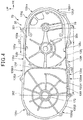
- Figure 4 is a side view illustrating the transmission case cover 35.
- the transmission case cover 35 of the transmission case 72 is comprised of a cover bottom portion 135f that is disposed inwardly in the vehicle width direction, and a cover peripheral wall 135g that rises outwardly in the vehicle width direction from the peripheral edge of the cover bottom portion 135f.
- a cover mating surface 135j that continues in a substantially ellipse shape in a side view is formed in a cover distal end portion 135h that forms an opening edge.
- the cover peripheral wall 135g includes a cover front peripheral wall 135m that is located forward of the front virtual straight line 201 (i.e., the crank axis line L1 (see Figure 3 )), a cover rear peripheral wall 135n that is located rearward of the rear virtual straight line 202 (i.e., the driven axis line L5 (see Figure 3 )), a cover upper peripheral wall 135p that connects an upper portion of the cover front peripheral wall 135m and an upper portion of the cover rear peripheral wall 135n, and a cover lower peripheral wall 135q that connects a lower portion of the cover front peripheral wall 135m and a lower portion of the cover rear peripheral wall 135n.
- the above-described cover peripheral wall 135g is divided into the cover front peripheral wall 135m, the cover rear peripheral wall 135n, the cover upper peripheral wall 135p, and the cover lower peripheral wall 135q by the front virtual straight line 201 and the rear virtual straight line 202.
- the cover distal end portion 135h includes a front distal end portion 135h1, a rear distal end portion 135h2, an upper distal end portion 135h3, and a lower distal end portion 135h4 that are included in the cover front peripheral wall 135m, the cover rear peripheral wall 135n, the cover upper peripheral wall 135p, and the cover lower peripheral wall 135q, respectively.
- the cover mating surface 135j includes a front mating surface 135j1, a rear mating surface 135j2, an upper mating surface 135j3, and a lower mating surface 135j4 that are included in the cover front peripheral wall 135m, the cover rear peripheral wall 135n, the cover upper peripheral wall 135p, and the cover lower peripheral wall 135q, respectively.
- the front mating surface 135j1 is formed in the front distal end portion 135h1
- the rear mating surface 135j2 is formed in the rear distal end portion 135h2
- the upper mating surface 135j3 is formed in the upper distal end portion 135h3
- the lower mating surface 135j4 is formed in the lower distal end portion 135h4.
- a cover upper recess 135s is formed at a corner between an inner peripheral surface 135r of the cover peripheral wall 135g and the upper mating surface 135j3.
- the cover upper recess 135s is formed at a position closer to the front virtual straight line 201 than the rear virtual straight line 202.
- a cover lower recess 135t is formed at a corner between the inner peripheral surface 135r of the cover peripheral wall 135g and the lower mating surface 135j4.
- the cover lower recess 135t is formed at a position closer to the rear virtual straight line 202 than the front virtual straight line 201.
- a front end of the cover upper recess 135s is on the front virtual straight line 201, and a distance between a front end of the cover lower recess 135t and the front virtual straight line 201 is set to L2.
- a front-rear length of the cover upper recess 135s is set to LG1 that is the same as the front-rear length of the main body upper recess 134s (see Figure 3 ).
- a front-rear length of the cover lower recess 135t is set to LG2 that is the same as the front-rear length of the main body lower recess 134t (see Figure 3 ).
- the main body upper recess 134s and the cover upper recess 135s overlap with each other in the vehicle width direction
- the main body lower recess 134t and the cover lower recess 135t overlap with each other in the vehicle width direction.
- the motorcycle 10 When the motorcycle 10 is accelerated, for example, under rotation of the belt 174, a large torque acts on the drive pulley 171 from the crankshaft 33, and a smaller torque than the torque acting on the drive pulley 171 acts on the driven pulley 173.
- the belt 174 located above the straight line 205 becomes a tension side of the belt 174
- the belt 174 located below the straight line 205 becomes a slack side of the belt 174.
- the belt 174 located below the straight line 205 is easily slackened near the driven pulley 173, and is likely to come in contact with a joining portion 72a between the main body lower peripheral wall 134q and the cover lower peripheral wall 135q.
- the front-rear length LG2 of the main body lower recess 134t and the cover lower recess 135t is longer than the front-rear length LG1 of the main body upper recess 134s and the cover upper recess 135s.
- Figure 5 is a cross-sectional view taken along line V-V of Figure 1 .
- an upper recess 72b and a lower recess 72c are formed in the upper portion and the lower portion of the joining portion 72a, respectively, so as to face a variable transmission chamber 86.
- the upper recess 72b is formed from the main body upper recess 134s and the cover upper recess 135s.
- the lower recess 72c is formed from the main body lower recess 134t and the cover lower recess 135t.
- reference sign 35a denotes a boss that is formed on an inner surface of the transmission case cover 35
- reference sign 35b denotes a through hole that is formed in the boss 35a to support the kick shaft 197 (see Figure 2 ).
- the upper recess 72b and the lower recess 72c that are formed in the mating surface 72 can prevent the belt 174 from coming into contact with the mating surface 72d.
- Figure 6 is an enlarged view of an area A of Figure 5 .
- the main body lower recess 134t of the main body lower peripheral wall 134q in the transmission case main body 34D includes a bottom surface 134w of the main body lower recess 134t and a side surface 134x that extends upwardly from the bottom surface 134w.
- a curved surface 134u is formed at a corner between the side surface 134x and the inner peripheral surface 134r of the main body lower peripheral wall 134q, the curved surface 134u protruding inward of the variable transmission chamber 86.
- the cover lower recess 135t of the cover lower peripheral wall 135q in the transmission case cover 35 includes a bottom surface 135w of the cover lower recess 135t and a side surface 135x that extends upwardly from the bottom surface 135w.
- a curved surface 135u is formed at a corner between the side surface 135x and the inner peripheral surface 135r of the cover lower peripheral wall 135q, the curved surface 135u protruding inward of the variable transmission chamber 86.
- a curved surface 134y is formed at a corner between the side surface of the main body upper recess 134s and the inner peripheral surface 134r of the main body upper peripheral wall 134p in the transmission case main body 34D, the curved surface 134y protruding inward of the variable transmission chamber 86 (see Figure 5 ).
- a curved surface 135y is formed at a corner between the side surface of the cover upper recess 135s and the inner peripheral surface 135r of the cover upper peripheral wall 135p in the transmission case cover 35, the curved surface 135y protruding inward of the variable transmission chamber 86 (see Figure 5 ).
- main body upper recess 134s, cover upper recess 135s, main body lower recess 134t, and cover lower recess 135t are molded by casting, thereby capable of being easily formed without increasing the number of components.
- Figure 7 is a left side view illustrating the transmission case main body 34D and the periphery thereof with the transmission case cover 35 and the drive pulley 171 (see Figure 3 ) removed.
- An oil separator mounting opening 134v on which an oil separator 83 is mounted is formed at a front portion of the main body bottom portion 134f of the transmission case main body 34D, and the oil separator 83 is mounted in the oil separator mounting opening 134v.
- An O-ring 88 (see Figure 8 ) seals between an outer peripheral surface 83a of the oil separator 83 and the oil separator mounting opening 134v.
- a through hole 83b into which the crankshaft 33 is inserted is opened in the oil separator 83.
- An oil pump 77 (see Figure 8 ) is disposed below the crankshaft 33.
- the oil pump 77 is connected to the oil pump driven gear 94 that meshes with an oil pump drive gear 93 attached to the crankshaft 33, so as to be driven by the drive force of the crankshaft 33.
- An outline of the oil pump driven gear 94 is provided to protrude outwardly in the radial direction from the oil separator mounting opening 134v in a side view of the vehicle. In other words, the oil pump driven gear 94 overlaps with the edge of the oil separator mounting opening 134v on the outer side in the vehicle width direction.
- the size of the oil separator mounting opening 134v is reduced, thereby capable of miniaturizing the transmission case main body 34D and thus the transmission case 72, and increasing the degree of freedom of the mounting position of the oil separator 83.
- an inner diameter of the oil separator mounting opening 134v is larger than an outer diameter of the oil pump driven gear 94 (addendum circle diameter)
- Figure 8 is a cross-sectional view taken along line VIII-VIII of Figure 7 .
- the oil pump drive gear 93 is fixed to the left shaft portion 33a of the crankshaft 33 to mesh with the oil pump driven gear 94.
- the oil pump 77 is attached to the oil pump driven gear 94.
- reference sign 33c denotes a counter weight that is provided to the crankshaft 33
- reference sign L1 denotes a crank axis line that is an axis line of the crankshaft 33.
- the oil pump driven gear 94 is formed integrally from a shaft portion 94a, and a driven gear 94b that is formed at the middle portion of the shaft portion 94a, and both end portions of the shaft portion 94a are rotatably supported by the left case 34A and the oil separator 83.
- the oil pump 77 is comprised of a pump recess 34z, a rotor assembly 77a, and a holding plate 77b.
- the pump recess 34z is formed by the left case 34A.
- the rotor assembly 77a is disposed in the pump recess 34z, and is engaged in one end portion of the shaft portion 94a of the oil pump driven gear 94.
- the holding plate 77b is attached to the left case 34A with a bolt 95 to be held the rotor assembly 77a from the side.
- the rotor assembly 77a includes an outer rotor 77c that is rotatably housed in the pump recess 34z and an inner rotor 77d that has a teeth portion that meshes with a teeth portion formed on an inner periphery surface of the outer rotor 77c and is disposed in the outer rotor 77c.
- the inner rotor 77d is engaged to one end portion of the shaft portion 94a to be rotatable together with the oil pump driven gear 94.
- reference sign 76 denotes an oil pan that is integrally provided in the lower portion of the crankcase 34
- reference sign 87 denotes an oil seal that seals between the crankshaft 33 and the oil separator 83
- reference sign 88 denotes an O-ring that seals between the left case 34A and the oil separator 83.
- the transmission case 72 that is integrally provided to the internal combustion engine 31 and is disposed lateral to the rear wheel 13 includes the transmission case main body 34D that extends laterally of the rear wheel 13 from the internal combustion engine 31 and is open at the opposite side to the rear wheel 13, and the transmission case cover 35 that, together with the transmission case main body 34D, forms the variable transmission chamber 86 and is connected to the transmission case main body 34D to close the open end of the transmission case main body 34D
- the transmission case main body 34D includes the main body bottom portion 134f that serves as a bottom portion located lateral to the rear wheel 13, and the main body peripheral wall 134g that serves as a first peripheral wall extending upwardly from the main body bottom portion 134f and in which the main body distal end portion 134h serving as a distal end portion is open
- the transmission case cover 35 includes the cover peripheral wall 135g that serves as a second peripheral wall to
- the main body distal end portion 134h of the main body peripheral wall 134g and the cover distal end portion 135h of the cover peripheral wall 135g are provided in a range of motion (movable range M) of the belt 174 in the axial direction of the crankshaft 33, and the main body upper recess 134s, the main body lower recess 134t, the cover upper recess 135s, and the cover lower recess 135t are formed as recesses that are recessed in a direction away from the belt 174, in the main body distal end portion 134h of the main body peripheral wall 134g and the cover distal end portion 135h of the cover peripheral wall 135g, along an extending direction of the straight line 205 (see Figure 3 ) connecting the crank axis line L1 as an axis line of the crankshaft 33 and the driven axis line L5 as an axis line of the driven shaft 172.
- the belt 174 can be prevented from coming into direct contact with the joining portion 72a between the main body peripheral wall 134g and the cover peripheral wall 135g even when the belt 174 vibrates in a direction orthogonal to the extending direction of the belt 174 to cause contact with the respective inner peripheral surfaces 134r, 135r of the main body peripheral wall 134g and the cover peripheral wall 135g of the transmission case 72. Accordingly, the degree of freedom of the position of the joining portion 72a between the transmission case main body 34D and the transmission case cover 35 can be secured, and the shaping flexibility of the transmission case main body 34D and the transmission case cover 35 can be also secured.
- the main body upper recess 134s and the main body lower recess 134t are formed continuously with the main body distal end portion 134h of the main body peripheral wall 134g, and the cover upper recess 135s and the cover lower recess 135t are formed integrally with the cover distal end portion 135h of the cover peripheral wall 135g, and the inner peripheral surface 134r of the main body peripheral wall 134g is connected to the main body upper recess 134s and the main body lower recess 134t through the curved surfaces 134y, 134u, respectively, and the inner peripheral surface 135r of the cover peripheral wall 135g is connected to the cover upper recess 135s and the cover lower recess 135t through the curved surfaces 135y, 135u, respectively.
- the cuved surfaces 134y, 134u, 135y, and 135u can eliminate sharp portions from portions including the peripheries of the main body upper recess 134s, the main body lower recess 134t, the cover upper recess 135s, and the cover lower recess 135t.
- the belt 174 can be prevented from coming into direct contact with the joining portion 72a between the main body peripheral wall 134g and the cover peripheral wall 135g, and the main body upper recess 134s and the main body lower recess 134t are formed within the limitations, thereby capable of simplifying the structure of the transmission case 72.
- the belt 174 can be prevented from coming into direct contact with the joining portion 72a between the main body peripheral wall 134g and the cover peripheral wall 135g, and the main body lower recess 134t is formed within the limitations, thereby capable of simplifying the structure of the transmission case.
- the belt 174 can be prevented from coming into direct contact with the joining portion 72a between the main body peripheral wall 134g and the cover peripheral wall 135g, and the main body upper recess 134s is formed within the limitations, thereby capable of simplifying the structure of the transmission case 72.
Landscapes
- Engineering & Computer Science (AREA)
- General Engineering & Computer Science (AREA)
- Mechanical Engineering (AREA)
- General Details Of Gearings (AREA)
- Transmissions By Endless Flexible Members (AREA)
Abstract
Description
- The present invention relates to a transmission case structure for a saddle-type vehicle power unit.
- There has been known a transmission case for a belt continuously variable transmission that is integrally provided to an internal combustion engine and is disposed lateral to a rear wheel, as a transmission case structure for a saddle-type vehicle power unit (for example, see Patent Literature 1).
- The transmission case includes a transmission case main body that extends laterally of the rear wheel from the internal combustion engine and is open at the opposite side to the rear wheel, and a transmission case that, together with the transmission case main body, forms a variable transmission chamber and is connected to the transmission case main body to close the open end of the transmission case main body.
- The variable transmission chamber is provided with a drive shaft that is rotated by a drive force of the internal combustion engine and a transmission shaft that is provided on the rear wheel side to transmit the drive force to the rear wheel, in which an endless belt is wound around a drive pulley that is attached to the drive shaft and a driven pulley that is attached to the transmission shaft.
- [Patent Literature 1] Japanese Patent Laid-Open No.
2013-257010 - In the power unit for a saddle-type vehicle having a transmission case disclosed in
Patent Literature 1, a belt is likely to vibrate in a direction orthogonal to an extending direction of the belt particularly, when the vehicle is accelerated or decelerated, and the belt may come into contact with an inner wall surface of the transmission case due to this vibration. - Since a slight positional deviation occurs at a joining portion between the transmission case main body and the transmission case cover due to dimensional errors, or the like when joining the transmission case main body and the transmission case cover, and a joined end surface is generally formed by cutting, it is necessary to separate a position of the joining portion from the belt in an axial direction so that the belt does not come into contact with the joining portion. Accordingly, the position of the joining portion is limited, and hence there is a problem in that it is difficult to secure the shaping flexibility of the transmission case main body and the transmission case cover.
- It is an object of the present invention to provide a transmission case structure for a saddle-type vehicle power unit that can prevent a belt from coming into contact with a joining portion of a transmission case and secure shaping flexibility of a transmission case main body and a transmission case cover.
- To solve the above problems, the present invention provides a transmission case structure for a saddled vehicle power unit in which a transmission case (72) that is integrally provided to an internal combustion engine (31) and is disposed lateral to a rear wheel (13) includes a transmission case main body (34D) that extends laterally of the rear wheel (13) from the internal combustion engine (31) and is open at an opposite side to the rear wheel (13), and a transmission case cover (35) that, together with the transmission case main body (34D), forms a variable transmission chamber (86) and is connected to the transmission case main body (34D) to close an open end of the transmission case main body (34D), the transmission case main body (34D) includes a bottom portion (134f) that is located lateral to the rear wheel (13), and a first peripheral wall (134g) that extends upwardly from the bottom portion (134f) and in which a distal end portion is open, the transmission case cover (35) includes a second peripheral wall (135g) that is to be connected to the distal end portion of the first peripheral wall (134g), the distal end portion of the first peripheral wall (134g) is connected to a distal end portion of the second peripheral wall (135g), so that the variable transmission chamber (86) is formed between the transmission case main body (34D) and the transmission case cover (35), and the variable transmission chamber (86) houses a drive pulley (171) that is attached to a drive shaft (33) rotated by a drive force generated from the internal combustion engine (31), a driven pulley (173) that is attached to a transmission shaft (172) provided on the rear wheel (13) side to transmit the drive force to the rear wheel (13), and an endless belt (174) that is wound around the drive pulley (171) and the driven pulley (173), wherein the distal end portion of the first peripheral wall (134g) and the distal end portion of the second peripheral wall (135g) are provided in a range of motion of the belt (174) in an axial direction of the drive shaft (33), and recesses (134s, 134t, 135s, 135t) are formed in the distal end portion of the first peripheral wall (134g) and the distal end portion of the second peripheral wall (135g) along an extending direction of a straight line (205) connecting an axis line (L1) of the drive shaft (33) and an axis line (L5) of the transmission shaft (172), the recesses being recessed in a direction away from the belt (174).
- In the above-described configuration, the recesses (134s, 134t) and the recesses (135s, 135t) may be formed continuously with distal end portions of the first peripheral wall (134g) and distal end portions of the second peripheral wall (135g), respectively, and an inner peripheral surface (134r) of the first peripheral wall (134g) and an inner peripheral surface (135r) of the second peripheral wall (135g) may be connected to the recesses (134s, 134t) and the recesses (135s, 135t) through curved surfaces (134y, 134u) and curved surfaces (135y, 135u), respectively.
- In the above-described configuration, in a side view of a vehicle, the recesses (134s, 134t, 135s, 135t) may be formed at least within a range between the axis line (L1) of the drive shaft (33) and the axis line (L5) of the transmission shaft (172) in each distal end portion of the first peripheral wall (134g) and the second peripheral wall (135g).
- In the above-described configuration, in a side view of a vehicle, the first peripheral wall (134g) may include a front peripheral wall (134m) that covers a front of the axis line (L1) of the drive shaft (33), a rear peripheral wall (134n) that covers a rear of the axis line (L5) of the transmission shaft (172), an upper peripheral wall (134p) that connects the front peripheral wall (134m) and the rear peripheral wall (134n), and a lower peripheral wall (134q) that connects the front peripheral wall (134m) and the rear peripheral wall (134n), so that the recesses (134s, 134t) are formed only in the upper peripheral wall (134p) and the lower peripheral wall (134q), respectively.
- In the above-described configuration, in a side view of a vehicle, the first peripheral wall (134g) may include a front peripheral wall (134m) that covers the front of the axis line (L1) of the drive shaft (33), a rear peripheral wall (134n) that covers the rear of the axis line (L5) of the transmission shaft (172), an upper peripheral wall (134p) that connects upper portions of the front peripheral wall (134m) and the rear peripheral wall (134n), and a lower peripheral wall (134q) that connects lower portions of the front peripheral wall (134m) and the rear peripheral wall (134n), so that the recesses (134s, 134t) are formed in the upper peripheral wall (134p) and the lower peripheral wall (134q), respectively, and a front-rear length of the recess (134t) formed in the lower peripheral wall (134q) is longer than that of the recess (134s) formed in the upper peripheral wall (134p).
- In the above-described configuration, in a side view of a vehicle, the first peripheral wall (134g) may include a front peripheral wall (134m) that covers the front of the axis line (L1) of the drive shaft (33), a rear peripheral wall (134n) that covers the rear of the axis line (L5) of the transmission shaft (172), an upper peripheral wall (134p) that connects upper portions of the front peripheral wall (134m) and the rear peripheral wall (134n), and a lower peripheral wall (134q) that connects lower portions of the front peripheral wall (134m) and the rear peripheral wall (134n), so that the recess (134t) is formed in the lower peripheral wall (134q), and the recess (134t) of the lower peripheral wall (134q) is formed at a position closer to the axis line (L5) of the transmission shaft (172) than the axis line (L1) of the drive shaft (33).
- In the above-described configuration, in a side view of a vehicle, the first peripheral wall (134g) may include a front peripheral wall (134m) that covers the front of the axis line (L1) of the drive shaft (33), a rear peripheral wall (134n) that covers the rear of the axis line (L5) of the transmission shaft (172), an upper peripheral wall (134p) that connects upper portions of the front peripheral wall (134m) and the rear peripheral wall (134n), and a lower peripheral wall (134q) that connects lower portions of the front peripheral wall (134m) and the rear peripheral wall (134n), so that the recess (134s) is formed in the upper peripheral wall (134p), and the recess (134s) of the upper peripheral wall (134p) is formed at a position closer to the axis line (L1) of the drive shaft (33) than the axis line (L5) of the transmission shaft (172).
- Since the distal end portion of the first peripheral wall and the distal end portion of the second peripheral wall of the present invention are provided in a range of motion of the belt in the axial direction of the drive shaft, and the recesses that are recessed in a direction away from the belt are formed in the distal end portion of the first peripheral wall and the distal end portion of the second peripheral wall along an extending direction of a straight line connecting an axis line of the drive shaft and an axis line of the transmission shaft, when a joining portion between the distal end portion of the first peripheral wall and the distal end portion of the second peripheral wall is formed to overlap with the belt in the axial direction of the drive shaft, the belt can be prevented from coming into direct contact with the joining portion between the first peripheral wall and the second peripheral wall even when the belt vibrates in a direction orthogonal to an extending direction of the belt and comes into contact with each inner wall surface of the first peripheral wall and the second peripheral wall of the transmission case. Accordingly, a degree of freedom of the position of the joining portion between the transmission case main body and the transmission case cover can be secured, and shaping flexibility of the transmission case main body and the transmission case cover can be also secured.
- Each of the recesses is formed continuously with each distal end portion of the first peripheral wall and the second peripheral wall, and is connected to each inner peripheral surface of the first peripheral wall and the second peripheral wall through a curved surface, thereby capable of eliminating sharp portions from portions including the peripheries of the recesses.
- Since in a side view of a vehicle, the recesses are formed at least within a range between the axis line of the drive shaft and the axis line of the transmission shaft in each distal end portion of the first peripheral wall and the second peripheral wall, in portions at least in the range between the axis line of the drive shaft and the axis line of the transmission shaft in each distal end portion of the first peripheral wall and the second peripheral wall, even when the belt is separated from the drive pulley and the driven pulley, and thus the belt is likely to vibrate in a direction orthogonal to the extending direction of the belt, the belt can be prevented from coming into direct contact with the joining portion between the first peripheral wall and the second peripheral wall by forming the recesses in the corresponding portions.
- Since, in a side view of the vehicle, the first peripheral wall includes the front periphery wall that covers the front of the axis line of the drive shaft, the rear peripheral wall that covers the rear of the axis line of the transmission shaft, the upper peripheral wall that connects the front peripheral wall and the rear peripheral wall, and the lower peripheral wall that connects the front peripheral wall and the rear peripheral wall, and the recesses are formed only in the upper peripheral wall and the lower peripheral wall, respectively, even when the belt is separated from the drive pulley and the driven pulley in the upper peripheral wall and the lower peripheral wall that are proximate to the belt, and thus the belt is likely to vibrate in a direction orthogonal to the extending direction of the belt, the belt can be prevented from coming into direct contact with the joining portion between the first peripheral wall and the second peripheral wall by forming the recesses only within the range between the axis line of the drive shaft and the axis line of the transmission shaft, and the structure of the transmission case can be simplified by forming the recesses within the limitations.
- Since, in a side view of the vehicle, the first peripheral wall includes the front peripheral wall that covers the front of the axis line of the drive shaft, the rear peripheral wall that covers the rear of the axis line of the transmission shaft, the upper peripheral wall that connects upper portions of the front peripheral wall and the rear peripheral wall, and the lower peripheral wall that connects lower portions of the front peripheral wall and the rear peripheral wall, the recesses are formed in the upper peripheral wall and the lower peripheral wall, and the front-rear length of the recess formed in the lower peripheral wall is longer than that of the recess formed in the upper peripheral wall, the inventors show the experiment result that when the belt vibrates, a contact area of the belt with the lower peripheral wall exists over a wider area in the front-rear direction than that with the upper peripheral wall. According to the above-described configuration, the belt can be prevented from coming into direct contact with the joining portion between the first peripheral wall and the second peripheral wall, and the structure of the transmission case can be simplified by forming the recesses within the limitations.
- Since, in a side view of the vehicle, the first peripheral wall includes the front peripheral wall that covers the front of the axis line of the drive shaft, the rear peripheral wall that covers the rear of the axis line of the transmission shaft, the upper peripheral wall that connects upper portions of the front peripheral wall and the rear peripheral wall, and the lower peripheral wall that connects lower portions of the front peripheral wall and the rear peripheral wall, so that the recess is formed in the lower peripheral wall, and the recess of the lower peripheral wall is formed at a position closer to the axis line of the transmission shaft than the axis line of the drive shaft, the belt located below the straight line connecting the axis line of the drive shaft and the axis line of the transmission shaft is easily slackened particularly when the vehicle is accelerated, and the belt is likely to come in contact with the lower peripheral wall near the driven pulley that becomes a winding side of the belt located below the above-described straight line. According to the above-described configuration, the belt can be prevented from coming into direct contact with the joining portion between the first peripheral wall and the second peripheral wall, and the structure of the transmission case can be simplified by forming the recesses within the limitations.
- Since, in a side view of the vehicle, the first peripheral wall includes the front peripheral wall that covers the front of the axis line of the drive shaft, the rear peripheral wall that covers the rear of the axis line of the transmission shaft, the upper peripheral wall that connects upper portions of the front peripheral wall and the rear peripheral wall, and the lower peripheral wall that connects lower portions of the front peripheral wall and the rear peripheral wall, so that the recess is formed in the upper peripheral wall, and the recess of the upper peripheral wall is formed at a position closer to the axis line of the drive shaft than the axis line of the transmission shaft, the belt located above the straight line connecting the axis line of the drive shaft and the axis line of the transmission shaft is easily slackened particularly when the vehicle is decelerated, and the belt is likely to come in contact with the upper peripheral wall near the drive pulley that becomes a winding side of the belt located above the above-described straight line. According to the above-described configuration, the belt can be prevented from coming into direct contact with the joining portion between the first peripheral wall and the second peripheral wall, and the structure of the transmission case can be simplified by forming the recesses within the limitations.
-
-
Figure 1 is a left side view of a main part of a motorcycle including a transmission case for a power unit according to the present invention. -
Figure 2 is a cross-sectional view illustrating a power unit. -
Figure 3 is a left side view illustrating a transmission case main body and its periphery in a state where a transmission case cover is removed from a transmission case. -
Figure 4 is a side view illustrating the transmission case cover. -
Figure 5 is a cross-sectional view taken along line V-V ofFigure 1 . -
Figure 6 is an enlarged view of an area A ofFigure 5 . -
Figure 7 is a left side view illustrating the transmission case main body and a periphery thereof with the transmission case cover and a drive pulley removed. -
Figure 8 is a cross-sectional view taken along line VIII-VIII ofFigure 7 . - An embodiment of the present invention will be described below with reference to the drawings.
- Note that in the explanation, directions such as front and rear, right and left, and upper and lower is the same as directions with respect to a vehicle body unless otherwise specially described. Also note that in the respective drawings, reference sign FR is indicative of a front side of the vehicle body, reference sign UP is indicative of an upper side of the vehicle body, and reference sign LH is indicative of a left side of the vehicle body.
-
Figure 1 is a left side view of a main part of amotorcycle 10 including atransmission case 72 for apower unit 12 according to the present invention. - The
motorcycle 10 is a saddle-type vehicle in which thepower unit 12 is vertically swingably supported by a lower portion of avehicle body frame 11, arear wheel 13 is mounted at a rear end portion of thepower unit 12, and a seat (not illuminated) is provided above thevehicle body frame 11. Note thatreference sign 178 denotes an output shaft serving as an axle of therear wheel 13. - The
vehicle body frame 11 includes a pair of left and rightrear frames 21 that extend upwardly to the rear direction, and alower support member 22 is attached to the left and rightrear frames 21. A lower portion of thepower unit 12 is swingably supported by thelower support member 22 through alink member 24. - The
power unit 12 is composed of a unit swing typeinternal combustion engine 31 that forms a front portion of thepower unit 12, and a continuouslyvariable transmission 32 that is disposed integrally with a rear portion of theinternal combustion engine 31. - The
internal combustion engine 31 includes acrankcase 34 in which acrankshaft 33 extending in a vehicle width direction is rotatably housed, and acylinder 36 that is attached to a front end portion of thecrankcase 34. Thecrankcase 34 is provided with thetransmission case 72 at a left side portion of thecrankcase 34, thetransmission case 72 forming the continuouslyvariable transmission 32. Thecylinder 36 is inclined upwardly to the front direction, and includes a cylinder block, acylinder head 38, and ahead cover 39 that are stacked in this order and assembled to thecrankcase 34, and the cylinder block and thecylinder head 38 are covered by ashroud 51 that is divided into two in the up-down direction. - An
air intake device 53 is connected to the upper portion of thecylinder head 38, and an exhaust device is connected to the lower portion of thecylinder head 38. - The
air intake device 53 includes anair intake pipe 54 that is attached to thecylinder head 38, athrottle body 56 that is connected to theair intake pipe 54, and anair cleaner 58 that is connected to thethrottle body 56 through a connecting tube. Note thatreference sign 34a denotes a pair of left and right hanger arms that are formed at a front lower portion of thecrankcase 34 to connect to thelink member 24,reference sign 46 denotes a main stand that is attached to a rear lower portion of thecrankcase 34, andreference sign 47 denotes a vehicle body cover that is provided below the seat to cover the upper portion of the vehicle body, the upper portion of theinternal combustion engine 31, and the like. -
Figure 2 is a cross-sectional view illustrating thepower unit 12. - The
crankcase 34 is comprised of aleft case 34A and aright case 34B into which thecrankcase 34 is divided in the left-right direction. Theleft case 34A is formed integrally with a rearward extendingportion 34C that extends rearwardly beyond theright case 34B, and a part of the front portion of theleft case 34A and the rearward extendingportion 34C form a transmission casemain body 34D. - The
crankshaft 33 includes aleft shaft portion 33a, aright shaft portion 33b, acrank pin 91, and a pair ofcounter weights left shaft portion 33a and theright shaft portion 33b are provided to extend to left and right sides of thecrankshaft 33 in the vehicle width direction, respectively, and are supported by theleft case 34A and theright case 34B throughbearings crank pin 91 is provided to extend in the vehicle width direction between theleft shaft portion 33a and theright shaft portion 33b. Thecounter weights crank pin 91 with respect to theleft shaft portion 33a and theright shaft portion 33b, respectively. - The
cylinder block 37 and thecylinder head 38 are fixed to thecrankcase 34 with a plurality ofbolts 151 so as to be stacked in this order. - The
cylinder block 37 is provided with acylindrical cylinder liner 152 inside thecylinder block 37, and apiston 153 is movably inserted into acylinder hole 152a that is formed in thecylinder liner 152. Thepiston pin 154 is fitted into thepiston 153 to extend along an axial direction of thecrankshaft 33, and thepiston pin 154 is connected to the crankpin 91 through a connectingrod 92. - In the
cylinder head 38, acombustion chamber 156 is formed on a joining surface between thecylinder block 37 and thecylinder head 38, and intake and exhaust valves and aspark plug 157 are disposed to face thecombustion chamber 156. Thecylinder head 38 includes avalve mechanism 161 including acamshaft 158 that drives intake and exhaust valves. Acam chain 164 is wound around acam drive sprocket 162 that is attached to theleft shaft portion 33a of thecrankshaft 33 and a cam drivensprocket 163 that is attached to one end portion of thecamshaft 158, and thecam chain 164 passes through acam chain chamber 36a that is formed to pass through thecylinder block 37 and thecylinder head 38. - An
AC generator 78 is provided to theright case 34B and theright shaft portion 33b. That is, astator support portion 34y is provided in theright case 34B, and astator 78A included in theAC generator 78 is fixed to thestator support portion 34y. A cup-shapedrotor support member 97 is attached to a distal end portion of theright shaft portion 33b with anut 96, and arotor 78B included in theAC generator 78 is attached to a peripheral wall of therotor support member 97. TheAC generator 78 includes the above-describedstator 78A androtor 78B, and therotor 78B is rotated in thestator 78A to generate the electric power. A coolingfan 63 is fixed to therotor support member 97 with a plurality ofbolts 98. Afan cover 61 is attached to a side of theright case 34B, and a coolingair intake port 61a is formed in thefan cover 61. The coolingfan 63 rotates by rotation of thecrankshaft 33 so that the external air is sucked from the coolingair intake port 61a into thefan cover 61, thereby capable of cooling each part of theinternal combustion engine 31 such as thecrankcase 34, and thecylinder 36. - The continuously
variable transmission 32 includes adrive pulley 171, a drivenshaft 172, a drivenpulley 173, abelt 174, acentrifugal clutch 176, areduction gear mechanism 177, anoutput shaft 178, and akick start mechanism 181. - The
drive pulley 171 is provided to theleft shaft portion 33a of thecrankshaft 33, and is composed of a drive-side left halfbody 171A that is fixed to theleft shaft portion 33a, and a drive-side righthalf body 171B that is provided to be incapable of rotating relative to theleft shaft portion 33a and be movable in the axial direction. The drive-side righthalf body 171B is biased toward the drive-side left halfbody 171A side by abiasing mechanism 183 when thecrankshaft 33 rotates at a predetermined rotational speed or more. Thebiasing mechanism 183 includes a biasingplate 184 that is fixed to theleft shaft portion 33a on a right side (the other side in the vehicle width direction) of the drive-side righthalf body 171B, and abiasing ball 186 that is disposed between the drive-side righthalf body 171B and the biasingplate 184. The drive-side righthalf body 171B and the biasingplate 184 have respective inclined portions that become closer to each other toward the outside in the radial direction. - The driven
shaft 172 is disposed behind theleft shaft portion 33a to be parallel to theleft shaft portion 33a. The drivenshaft 172 is rotatably supported by the transmission casemain body 34D through abearing 188. The drivenshaft 172 is provided with the drivenpulley 173. The drivenpulley 173 is composed of a driven-side left halfbody 173A that is provided to be incapable of rotating relative to the drivenshaft 172 and be movable in the axial direction, and a driven-side righthalf body 173B that is fixed to the drivenshaft 172. - The
belt 174 is wound around thedrive pulley 171 and the drivenpulley 173. - The
centrifugal clutch 176 that is disposed on the left side (one side in the vehicle width direction) of the driven-side left halfbody 173A is connected to the driven-side left halfbody 173A. Thecentrifugal clutch 176 includes an input-sideinner rotation portion 176A that rotates together with the left-side left halfbody 173A, and adrum 176B that is formed in a cup shape so as to surround theinner rotation portion 176A and is fixed to the drivenshaft 172. Theinner rotation portion 176A is provided with a plurality ofclutch shoes 176C that swing by centrifugal forces and extend outwardly in the radial direction, and theclutch shoes 176C are configured to be connected to or separated from thedrum 176B according to the rotational speed of the drivenpulley 173. - The
reduction gear mechanism 177 is provided on the downstream side of the drive force from the drivenshaft 172 on the right side of the drivenpulley 173. Thereduction gear mechanism 177 includes the rearward extendingportion 34C of theleft case 34A, a drivenshaft gear portion 172a of the drivenshaft 172, anintermediate gear 191, anintermediate shaft 192, anoutput gear 193, and a reductiongear mechanism cover 194. - The
intermediate gear 191 that is fixed to theintermediate shaft 192 meshes with the drivenshaft gear portion 172a. An intermediateshaft gear portion 192a is formed in theintermediate shaft 192, and theoutput gear 193 that is fixed to theoutput shaft 178 meshes with the intermediateshaft gear portion 192a. The rearward extendingportion 34C and the reductiongear mechanism cover 194 that is attached to the outer side surface of the rearward extendingportion 34C form a speedreduction unit case 196 of thereduction gear mechanism 177. - A right-side end portion of the driven
shaft 172, both end portions of theintermediate shaft 192, and the left end portion and the middle portion in the vehicle width direction of theoutput shaft 178 are supported by the rearward extendingportion 34C and the reductiongear mechanism cover 194 through the respective bearings. Therear wheel 13 is attached to theoutput shaft 178. - The
kick start mechanism 181 is provided to a transmission case cover 35. Thekick start mechanism 181 includes akick shaft 197 that is pivotally supported by the transmission case cover 35, akick drive gear 198 that is fixed to an end portion located inside in the vehicle width direction of thekick shaft 197, areturn spring 199 that returns the rotation of thekick drive gear 198, and a kick arm that is attached to an end portion located outside in the vehicle width direction of thekick shaft 197. Thekick shaft 197 is disposed parallel to thecrankshaft 33. Thekick drive gear 198 meshes with the kick drivengear portion 33e that is formed in theleft shaft portion 33a of thecrankshaft 33. - The operation of the continuously
variable transmission 32 described above will be described below. - When the
crankshaft 33 starts to rotate, thedrive pulley 171 rotates in a state where the drive-side righthalf body 171B is located at a predetermined position farthest from the drive-side left halfbody 171A until the rotational speed of thecrankshaft 33 reaches a predetermined rotational speed. The winding radius of thebelt 174 with respect to the drivepulley 171 at this moment becomes the smallest. To the contrary, the winding radius of thebelt 174 with respect to the drivenpulley 173 becomes the largest. Accordingly, a gear ratio between thecrankshaft 33 and the drivenshaft 172 becomes larger. - When the rotational speed of the
crankshaft 33 is equal to or greater than the predetermined rotational speed, the biasingball 186 rotates together with the drive-side righthalf body 171B and the biasingplate 184, and the biasingball 186 moves outwardly in the radial direction under centrifugal forces to push the inclined portion of the drive-side righthalf body 171B toward the left side in the axial direction of theleft shaft portion 33a, so that the drive-side righthalf body 171B moves toward the drive-side left halfbody 171A side. As a result, the winding radius ofbelt 174 with respect to the drivepulley 171 becomes larger, but the winding radius ofbelt 174 with respect to the drivenpulley 173 becomes smaller, resulting that the gear ratio between thecrankshaft 33 and the drivenshaft 172 becomes smaller. The gear ratio changes steplessly according to an axial position of the drive-side righthalf body 171B of thedrive pulley 171. - In the driven
pulley 173, when the driven-side left halfbody 173A and theinner rotation portion 176A of thecentrifugal clutch 176 are rotating together, the centrifugal forces acting on theclutch shoes 176C of theinner rotation portion 176A are small until the rotational speed of the driven-side left halfbody 173A reaches a fixed rotational speed, and therefore theclutch shoes 176C is separated from thedrum 176B. When the rotational speed of the driven-side left halfbody 173A is equal to or greater than a fixed rotational speed, theclutch shoes 176C come into contact with the inner peripheral surface of thedrum 176B due to the centrifugal forces, and then thecentrifugal clutch 176 is connected. That is, the drive force is transmitted from theinner rotation portion 176A to the drivenshaft 172 through thedrum 176B. - The drive force transmitted to the driven
shaft 172 is transmitted to theoutput shaft 178 through each gear (the drivenshaft gear portion 172a, theintermediate gear 191, the intermediateshaft gear portion 192a, and the output gear 193) of thereduction gear mechanism 177, thereby enabling therear wheel 13 to be rotated. -
Figure 3 is a left side view illustrating the transmission casemain body 34D and its periphery in a state where the transmission case cover 35 (seeFigure 2 ) is removed from the continuouslyvariable transmission 32. - The transmission case
main body 34D of thetransmission case 72 is comprised of a mainbody bottom portion 134f that is disposed inwardly in the vehicle width direction, and a main bodyperipheral wall 134g that rises outwardly in the vehicle width direction from the peripheral edge of the mainbody bottom portion 134f. In the main bodyperipheral wall 134g, a mainbody mating surface 134j that continues in a substantially ellipse shape in a side view is formed in a main bodydistal end portion 134h that forms an opening edge of the main bodyperipheral wall 134g. - The main body
peripheral wall 134g includes a main body frontperipheral wall 134m that is located forward of the crank axis line L1 that is an axis line of thecrankshaft 33, a main body rearperipheral wall 134n that is located rearward of the driven axis line L5 that is an axis line of the drivenshaft 172, a main body upperperipheral wall 134p that connects an upper portion of the main body frontperipheral wall 134m and an upper portion of the main body rearperipheral wall 134n, and a main body lowerperipheral wall 134q that connects a lower portion of the main body frontperipheral wall 134m and a lower portion of the main body rearperipheral wall 134n. Note thatreference sign 201 denotes a front virtual straight line that extends vertically through the crank axis line L1, andreference sign 202 denotes a rear virtual straight line that extends vertically through the driven axis line L5. - The above-described main body
peripheral wall 134g is divided into the main body frontperipheral wall 134m, the main body rearperipheral wall 134n, the main body upperperipheral wall 134p, and the main body lowerperipheral wall 134q by the front virtualstraight line 201 and the rear virtualstraight line 202. - The main body
distal end portion 134h includes a front distal end portion 134h1, a rear distal end portion 134h2, an upper distal end portion 134h3, and a lower distal end portion 134h4 that are included in the main body frontperipheral wall 134m, the main body rearperipheral wall 134n, the main body upperperipheral wall 134p, and the main body lowerperipheral wall 134q, respectively. - The main
body mating surface 134j includes a front mating surface 134j1, a rear mating surface 134j2, an upper mating surface 134j3, and a lower mating surface 134j4 that are included in the main body frontperipheral wall 134m, the main body rearperipheral wall 134n, the main body upperperipheral wall 134p, and the main body lowerperipheral wall 134q, respectively. - The front mating surface 134j1 is formed in the front distal end portion 134h1, the rear mating surface 134j2 is formed in the rear distal end portion 134h2, the upper mating surface 134j3 is formed in the upper distal end portion 134h3, and the lower mating surface 134j4 is formed in the lower distal end portion 134h4.
- In the upper distal end portion 134h3, a main body
upper recess 134s is formed at a corner between an innerperipheral surface 134r of the main bodyperipheral wall 134g and the upper mating surface 134j3. The main bodyupper recess 134s is formed at a position closer to the front virtualstraight line 201 than the rear virtualstraight line 202. - In the lower distal end portion 134h4, a main body
lower recess 134t is formed at a corner between the innerperipheral surface 134r of the main bodyperipheral wall 134g and the lower mating surface 134j4. The main bodylower recess 134t is formed at a position closer to the rear virtualstraight line 202 than the front virtualstraight line 201. - A front end of the main body
upper recess 134s is on the front virtualstraight line 201, and a distance between a front end of the main bodylower recess 134t and the front virtualstraight line 201 is set to L2. - A front-rear length LG2 of the main body
lower recess 134t is longer than a front-rear length LG1 of the main bodyupper recess 134s. Note thatreference sign 205 denotes a straight line that connects the crank axis line L1 that is the axis line of thecrankshaft 33 and the driven axis line L5 that is the axis line of the drivenshaft 172. Note that each of LG1 and LG2 may be a length along thestraight line 205. -
Figure 4 is a side view illustrating the transmission case cover 35. - The transmission case cover 35 of the
transmission case 72 is comprised of acover bottom portion 135f that is disposed inwardly in the vehicle width direction, and a coverperipheral wall 135g that rises outwardly in the vehicle width direction from the peripheral edge of thecover bottom portion 135f. In the coverperipheral wall 135g, acover mating surface 135j that continues in a substantially ellipse shape in a side view is formed in a coverdistal end portion 135h that forms an opening edge. - The cover
peripheral wall 135g includes a cover frontperipheral wall 135m that is located forward of the front virtual straight line 201 (i.e., the crank axis line L1 (seeFigure 3 )), a cover rearperipheral wall 135n that is located rearward of the rear virtual straight line 202 (i.e., the driven axis line L5 (seeFigure 3 )), a cover upperperipheral wall 135p that connects an upper portion of the cover frontperipheral wall 135m and an upper portion of the cover rearperipheral wall 135n, and a cover lowerperipheral wall 135q that connects a lower portion of the cover frontperipheral wall 135m and a lower portion of the cover rearperipheral wall 135n. - The above-described cover
peripheral wall 135g is divided into the cover frontperipheral wall 135m, the cover rearperipheral wall 135n, the cover upperperipheral wall 135p, and the cover lowerperipheral wall 135q by the front virtualstraight line 201 and the rear virtualstraight line 202. - The cover
distal end portion 135h includes a front distal end portion 135h1, a rear distal end portion 135h2, an upper distal end portion 135h3, and a lower distal end portion 135h4 that are included in the cover frontperipheral wall 135m, the cover rearperipheral wall 135n, the cover upperperipheral wall 135p, and the cover lowerperipheral wall 135q, respectively. - The
cover mating surface 135j includes a front mating surface 135j1, a rear mating surface 135j2, an upper mating surface 135j3, and a lower mating surface 135j4 that are included in the cover frontperipheral wall 135m, the cover rearperipheral wall 135n, the cover upperperipheral wall 135p, and the cover lowerperipheral wall 135q, respectively. - The front mating surface 135j1 is formed in the front distal end portion 135h1, the rear mating surface 135j2 is formed in the rear distal end portion 135h2, the upper mating surface 135j3 is formed in the upper distal end portion 135h3, and the lower mating surface 135j4 is formed in the lower distal end portion 135h4.
- In the upper distal end portion 135h3, a cover
upper recess 135s is formed at a corner between an innerperipheral surface 135r of the coverperipheral wall 135g and the upper mating surface 135j3. The coverupper recess 135s is formed at a position closer to the front virtualstraight line 201 than the rear virtualstraight line 202. - In the lower distal end portion 135h4, a cover
lower recess 135t is formed at a corner between the innerperipheral surface 135r of the coverperipheral wall 135g and the lower mating surface 135j4. The coverlower recess 135t is formed at a position closer to the rear virtualstraight line 202 than the front virtualstraight line 201. - A front end of the cover
upper recess 135s is on the front virtualstraight line 201, and a distance between a front end of the coverlower recess 135t and the front virtualstraight line 201 is set to L2. - A front-rear length of the cover
upper recess 135s is set to LG1 that is the same as the front-rear length of the main bodyupper recess 134s (seeFigure 3 ). A front-rear length of the coverlower recess 135t is set to LG2 that is the same as the front-rear length of the main bodylower recess 134t (seeFigure 3 ). InFigure 3 andFigure 4 , in a state where the transmission case cover 35 is assembled to the transmission casemain body 34D, the main bodyupper recess 134s and the coverupper recess 135s overlap with each other in the vehicle width direction, and the main bodylower recess 134t and the coverlower recess 135t overlap with each other in the vehicle width direction. - In
Figure 3 andFigure 4 , when the motorcycle 10 (seeFigure 1 ) is decelerated, for example, under rotation of thebelt 174, thedrive pulley 171 experiences a sudden decrease in the rotational speed together with thecrankshaft 33, and the drivenpulley 173 experiences a more gentle decrease in the rotational speed than thedrive pulley 171, together with therear wheel 13 and the drivenshaft 172. Thus, since the rotational speed of the drivenpulley 173 is higher than that of thedrive pulley 171, thebelt 174 located above thestraight line 205 becomes a slack side of thebelt 174, and thebelt 174 located below thestraight line 205 becomes a tension side of thebelt 174. Particularly, thebelt 174 located above thestraight line 205 is easily slackened near thedrive pulley 171, and is likely to come in contact with a joiningportion 72a (seeFigure 5 ) between the main body upperperipheral wall 134p and the cover upperperipheral wall 135p. - The upper mating surfaces 134j3, 135j3 are located in the joining
portion 72a. On the edges of the upper mating surfaces 134j3, 135j3 in the as-processed condition, burrs and the like may be generated, or a level difference between the upper mating surfaces 134j3, 135j3 may occur after joining the upper mating surfaces 134j3, 135j3. Since thebelt 174 may come into contact with the upper mating surfaces 134j3, 135j3 having such burrs or level difference, in the present embodiment, the main bodyupper recess 134s and the coverupper recess 135s are formed on the upper mating surfaces 134j3, 135j3, respectively. - When the
motorcycle 10 is accelerated, for example, under rotation of thebelt 174, a large torque acts on thedrive pulley 171 from thecrankshaft 33, and a smaller torque than the torque acting on thedrive pulley 171 acts on the drivenpulley 173. Thus, thebelt 174 located above thestraight line 205 becomes a tension side of thebelt 174, and thebelt 174 located below thestraight line 205 becomes a slack side of thebelt 174. Particularly, thebelt 174 located below thestraight line 205 is easily slackened near the drivenpulley 173, and is likely to come in contact with a joiningportion 72a between the main body lowerperipheral wall 134q and the cover lowerperipheral wall 135q. - On the edges of the lower mating surfaces 134j4, 135j4 located in the joining
portion 72a, in the as-processed condition, burrs and the like may be generated, or a level difference between the lower mating surfaces 134j4, 135j4 may occur after joining the lower mating surfaces 134j4, 135j4. Since thebelt 174 may come into contact with the lower mating surfaces 134j4, 135j4 having such burrs or level difference, in the present embodiment, the main bodylower recess 134t and the coverlower recess 135t are formed on the lower mating surfaces 134j4, 135j4, respectively. - The front-rear length LG2 of the main body
lower recess 134t and the coverlower recess 135t is longer than the front-rear length LG1 of the main bodyupper recess 134s and the coverupper recess 135s. This is based on the inventors' experiment result that when thebelt 174 vibrates up and down, a contact area of thebelt 174 with the main body lowerperipheral wall 134q and the cover lowerperipheral wall 135q exists over a wider area in the front-rear direction than that with the main body upperperipheral wall 134p and the cover upperperipheral wall 135p. -
Figure 5 is a cross-sectional view taken along line V-V ofFigure 1 . - In the joining
portion 72a between the transmission casemain body 34D and the transmission case cover 35 of thetransmission case 72, anupper recess 72b and alower recess 72c are formed in the upper portion and the lower portion of the joiningportion 72a, respectively, so as to face avariable transmission chamber 86. Theupper recess 72b is formed from the main bodyupper recess 134s and the coverupper recess 135s. Thelower recess 72c is formed from the main bodylower recess 134t and the coverlower recess 135t. - A
mating surface 72d of the joiningportion 72a is a surface that is formed from the mainbody mating surface 134j (seeFigure 3 ) and thecover mating surface 135j (seeFigure 4 ) when the mainbody mating surface 134j is mated with thecover mating surface 135j, and is located inside the movable range M along in the axial direction of thecrankshaft 33 in thebelt 174. - The
belt 174 indicated by a solid line is located on an innermost side in the vehicle width direction so that the winding radius of thebelt 174 on thedrive pulley 171 is the smallest. Thebelt 174 indicated by a virtual line is located on an outermost side in the vehicle width direction so that the winding radius of thebelt 174 on thedrive pulley 171 is the largest. A moving range in the vehicle width direction of the above-describedbelt 174 indicated by the solid line andbelt 174 indicated by the virtual line is represented as the movable range M. - Note that
reference sign 35a denotes a boss that is formed on an inner surface of the transmission case cover 35, andreference sign 35b denotes a through hole that is formed in theboss 35a to support the kick shaft 197 (seeFigure 2 ). - As described above, even when the
mating surface 72d of the joiningportion 72a is provided in the movable range M of thebelt 174, theupper recess 72b and thelower recess 72c that are formed in themating surface 72 can prevent thebelt 174 from coming into contact with themating surface 72d. -
Figure 6 is an enlarged view of an area A ofFigure 5 . - The main body
lower recess 134t of the main body lowerperipheral wall 134q in the transmission casemain body 34D includes abottom surface 134w of the main bodylower recess 134t and aside surface 134x that extends upwardly from thebottom surface 134w. Acurved surface 134u is formed at a corner between theside surface 134x and the innerperipheral surface 134r of the main body lowerperipheral wall 134q, thecurved surface 134u protruding inward of thevariable transmission chamber 86. - The cover
lower recess 135t of the cover lowerperipheral wall 135q in the transmission case cover 35 includes abottom surface 135w of the coverlower recess 135t and aside surface 135x that extends upwardly from thebottom surface 135w. Acurved surface 135u is formed at a corner between theside surface 135x and the innerperipheral surface 135r of the cover lowerperipheral wall 135q, thecurved surface 135u protruding inward of thevariable transmission chamber 86. - Note that the virtual line in
Figure 6 represents an inner peripheral surface of a conventional transmission case. - In
Figure 3 , acurved surface 134y is formed at a corner between the side surface of the main bodyupper recess 134s and the innerperipheral surface 134r of the main body upperperipheral wall 134p in the transmission casemain body 34D, thecurved surface 134y protruding inward of the variable transmission chamber 86 (seeFigure 5 ). InFigure 4 , acurved surface 135y is formed at a corner between the side surface of the coverupper recess 135s and the innerperipheral surface 135r of the cover upperperipheral wall 135p in the transmission case cover 35, thecurved surface 135y protruding inward of the variable transmission chamber 86 (seeFigure 5 ). - The above-described main body
upper recess 134s, coverupper recess 135s, main bodylower recess 134t, and coverlower recess 135t are molded by casting, thereby capable of being easily formed without increasing the number of components. -
Figure 7 is a left side view illustrating the transmission casemain body 34D and the periphery thereof with the transmission case cover 35 and the drive pulley 171 (seeFigure 3 ) removed. - An oil
separator mounting opening 134v on which anoil separator 83 is mounted is formed at a front portion of the mainbody bottom portion 134f of the transmission casemain body 34D, and theoil separator 83 is mounted in the oilseparator mounting opening 134v. An O-ring 88 (seeFigure 8 ) seals between an outerperipheral surface 83a of theoil separator 83 and the oilseparator mounting opening 134v. - A through
hole 83b into which thecrankshaft 33 is inserted is opened in theoil separator 83. An oil pump 77 (seeFigure 8 ) is disposed below thecrankshaft 33. - The
oil pump 77 is connected to the oil pump drivengear 94 that meshes with an oilpump drive gear 93 attached to thecrankshaft 33, so as to be driven by the drive force of thecrankshaft 33. - An outline of the oil pump driven
gear 94 is provided to protrude outwardly in the radial direction from the oilseparator mounting opening 134v in a side view of the vehicle. In other words, the oil pump drivengear 94 overlaps with the edge of the oilseparator mounting opening 134v on the outer side in the vehicle width direction. - Thus, the size of the oil
separator mounting opening 134v is reduced, thereby capable of miniaturizing the transmission casemain body 34D and thus thetransmission case 72, and increasing the degree of freedom of the mounting position of theoil separator 83. Note that since an inner diameter of the oilseparator mounting opening 134v is larger than an outer diameter of the oil pump driven gear 94 (addendum circle diameter), no problem exists in assembling the oil pump drivengear 94 to the inside of transmission casemain body 34D through the oilseparator mounting opening 134v. -
Figure 8 is a cross-sectional view taken along line VIII-VIII ofFigure 7 . - The oil
pump drive gear 93 is fixed to theleft shaft portion 33a of thecrankshaft 33 to mesh with the oil pump drivengear 94. Theoil pump 77 is attached to the oil pump drivengear 94. Note thatreference sign 33c denotes a counter weight that is provided to thecrankshaft 33, and reference sign L1 denotes a crank axis line that is an axis line of thecrankshaft 33. - The oil pump driven
gear 94 is formed integrally from ashaft portion 94a, and a drivengear 94b that is formed at the middle portion of theshaft portion 94a, and both end portions of theshaft portion 94a are rotatably supported by theleft case 34A and theoil separator 83. - The
oil pump 77 is comprised of a pump recess 34z, arotor assembly 77a, and a holdingplate 77b. - The pump recess 34z is formed by the
left case 34A. Therotor assembly 77a is disposed in the pump recess 34z, and is engaged in one end portion of theshaft portion 94a of the oil pump drivengear 94. The holdingplate 77b is attached to theleft case 34A with abolt 95 to be held therotor assembly 77a from the side. - The
rotor assembly 77a includes anouter rotor 77c that is rotatably housed in the pump recess 34z and aninner rotor 77d that has a teeth portion that meshes with a teeth portion formed on an inner periphery surface of theouter rotor 77c and is disposed in theouter rotor 77c. Theinner rotor 77d is engaged to one end portion of theshaft portion 94a to be rotatable together with the oil pump drivengear 94. Note thatreference sign 76 denotes an oil pan that is integrally provided in the lower portion of thecrankcase 34,reference sign 87 denotes an oil seal that seals between thecrankshaft 33 and theoil separator 83, andreference sign 88 denotes an O-ring that seals between theleft case 34A and theoil separator 83. - In
Figure 1 ,Figure 2 , andFigure 5 , in the transmission case structure for the power unit 12 for the motorcycle 10 as a saddle-type vehicle, the transmission case 72 that is integrally provided to the internal combustion engine 31 and is disposed lateral to the rear wheel 13 includes the transmission case main body 34D that extends laterally of the rear wheel 13 from the internal combustion engine 31 and is open at the opposite side to the rear wheel 13, and the transmission case cover 35 that, together with the transmission case main body 34D, forms the variable transmission chamber 86 and is connected to the transmission case main body 34D to close the open end of the transmission case main body 34D, the transmission case main body 34D includes the main body bottom portion 134f that serves as a bottom portion located lateral to the rear wheel 13, and the main body peripheral wall 134g that serves as a first peripheral wall extending upwardly from the main body bottom portion 134f and in which the main body distal end portion 134h serving as a distal end portion is open, the transmission case cover 35 includes the cover peripheral wall 135g that serves as a second peripheral wall to be connected to the main body distal end portion 134h of the main body peripheral wall 134g, the main body distal end portion 134h of the main body peripheral wall 134g is connected to the cover distal end portion 135h that is a distal end portion of the cover peripheral wall 135g, so that the variable transmission chamber 86 is formed between the transmission case main body 34D and the transmission case cover 35, and the variable transmission chamber 86 houses the drive pulley 171 that is attached to the crankshaft 33 as a drive shaft rotated by the drive force generated from the internal combustion engine 31, the driven pulley 173 that is attached to the driven shaft 172 as a transmission shaft provided on the rear wheel 13 side to transmit the drive force to the rear wheel 13, and the endless belt 174 that is wound around the drive pulley 171 and the driven pulley 173. The main bodydistal end portion 134h of the main bodyperipheral wall 134g and the coverdistal end portion 135h of the coverperipheral wall 135g are provided in a range of motion (movable range M) of thebelt 174 in the axial direction of thecrankshaft 33, and the main bodyupper recess 134s, the main bodylower recess 134t, the coverupper recess 135s, and the coverlower recess 135t are formed as recesses that are recessed in a direction away from thebelt 174, in the main bodydistal end portion 134h of the main bodyperipheral wall 134g and the coverdistal end portion 135h of the coverperipheral wall 135g, along an extending direction of the straight line 205 (seeFigure 3 ) connecting the crank axis line L1 as an axis line of thecrankshaft 33 and the driven axis line L5 as an axis line of the drivenshaft 172. - According to this configuration, when the main body
distal end portion 134h of the main bodyperipheral wall 134g and the coverdistal end portion 135h of the coverperipheral wall 135g are formed so as to overlap with thebelt 174 in the axial direction of thecrankshaft 33, thebelt 174 can be prevented from coming into direct contact with the joiningportion 72a between the main bodyperipheral wall 134g and the coverperipheral wall 135g even when thebelt 174 vibrates in a direction orthogonal to the extending direction of thebelt 174 to cause contact with the respective innerperipheral surfaces peripheral wall 134g and the coverperipheral wall 135g of thetransmission case 72. Accordingly, the degree of freedom of the position of the joiningportion 72a between the transmission casemain body 34D and the transmission case cover 35 can be secured, and the shaping flexibility of the transmission casemain body 34D and the transmission case cover 35 can be also secured. - In
Figure 3 through Figure 6 , the main bodyupper recess 134s and the main bodylower recess 134t are formed continuously with the main bodydistal end portion 134h of the main bodyperipheral wall 134g, and the coverupper recess 135s and the coverlower recess 135t are formed integrally with the coverdistal end portion 135h of the coverperipheral wall 135g, and the innerperipheral surface 134r of the main bodyperipheral wall 134g is connected to the main bodyupper recess 134s and the main bodylower recess 134t through thecurved surfaces peripheral surface 135r of the coverperipheral wall 135g is connected to the coverupper recess 135s and the coverlower recess 135t through thecurved surfaces belt 174 comes into contact with the peripheries of the main bodyupper recess 134s, the main bodylower recess 134t, the coverupper recess 135s, and the coverlower recess 135t, thecuved surfaces upper recess 134s, the main bodylower recess 134t, the coverupper recess 135s, and the coverlower recess 135t. - In
Figure 3 andFigure 4 , since the main body upper recess 134s, the main body lower recess 134t, the cover upper recess 135s, and the cover lower recess 135t are formed at least within a range between the crank axis line L1 of the crankshaft 33 and the driven axis line L5 of the driven shaft 172 in the main body distal end portion 134h of the main body peripheral wall 134g and the cover distal end portion 135h of the cover peripheral wall 135g, in a side view of the vehicle, in portions at least within the range between the crank axis line L1 and the driven axis line L5 in the main body distal end portion 134h of the main body peripheral wall 134g and the cover distal end portion 135h of the cover peripheral wall 135g, even when the belt 174 is separated from the drive pulley 171 and the driven pulley 173, and thus the belt 174 is likely to vibrate in a direction orthogonal to the extending direction of the belt 174, the belt 174 can be prevented from coming into direct contact with the joining portion 72a between the main body peripheral wall 134g and the cover peripheral wall 135g by forming the main body upper recess 134s, the main body lower recess 134t, the cover upper recess 135s, and the cover lower recess 135t in the above-described portions. - In
Figure 3 , since the main body peripheral wall 134g includes the main body front peripheral wall 134m that serves as a front peripheral wall covering the front of the crank axis line L1 of the crankshaft 33, the main body rear peripheral wall 134n that serves as a rear peripheral wall covering the rear of the driven axis line L5 of the driven shaft 172, the main body upper peripheral wall 134p that serves an upper peripheral wall connecting the main body front peripheral wall 134m and the main body rear peripheral wall 134n, and the main body lower peripheral wall 134q that serves as a lower peripheral wall connecting the main body front peripheral wall 134m and the main body rear peripheral wall 134n, and the main body upper recess 134s and the main body lower recess 134t are formed only in the main body upper peripheral wall 134p and the main body lower peripheral wall 134q, respectively, in a side view of the vehicle, even when the belt 174 is separated from the drive pulley 171 and the driven pulley 173 in the main body upper peripheral wall 134p and the main body lower peripheral wall 134q that are proximate to the belt 174, and thus the belt 174 is likely to vibrate in a direction orthogonal to the extending direction of the belt 174, the belt 174 can be prevented from coming into direct contact with the joining portion 72a between the main body peripheral wall 134g and the cover peripheral wall 135g by forming the main body upper recess 134s and the main body lower recess 134t only within the range between the crank axis line L1 and the driven axis line L5. Accordingly, thebelt 174 can be prevented from coming into direct contact with the joiningportion 72a between the main bodyperipheral wall 134g and the coverperipheral wall 135g, and the main bodyupper recess 134s and the main bodylower recess 134t are formed within the limitations, thereby capable of simplifying the structure of thetransmission case 72. - In
Figure 3 , since the main bodyupper recess 134s and the main bodylower recess 134t are formed in the main body upperperipheral wall 134p and the main body lowerperipheral wall 134q, respectively, and the front-rear length of the main bodylower recess 134t formed in the main body lowerperipheral wall 134q is longer than that of the main bodyupper recess 134s formed in the main body upperperipheral wall 134p, the inventors show the experiment result that when thebelt 174 vibrates, a contact area of the belt with the main body lowerperipheral wall 134q exists over a wider area in the front-rear direction than that with the main body upperperipheral wall 134p. According to the above-described configuration, thebelt 174 can be prevented from coming into direct contact with the joiningportion 72a between the main bodyperipheral wall 134g and the coverperipheral wall 135g, and the main bodyupper recess 134s and the main bodylower recess 134t are formed within the limitations, thereby capable of simplifying the structure of thetransmission case 72. - In
Figure 3 , since the main bodylower recess 134t is formed in the main body lowerperipheral wall 134q, and the main bodylower recess 134t of the main body lowerperipheral wall 134q is formed at a position closer to the driven axis line L5 than the crank axis line L1, thebelt 174 located below thestraight line 205 connecting the crank axis line L1 and the driven axis line L5 is easily slackened particularly when the vehicle is accelerated, and thebelt 174 is likely to come in contact with the main body lowerperipheral wall 134q near the drivenpulley 173 that becomes a winding side of thebelt 174 located below the above-describedstraight line 205. According to the above-described configuration, thebelt 174 can be prevented from coming into direct contact with the joiningportion 72a between the main bodyperipheral wall 134g and the coverperipheral wall 135g, and the main bodylower recess 134t is formed within the limitations, thereby capable of simplifying the structure of the transmission case. - In
Figure 3 , since the main bodyupper recess 134s is formed in the main body upperperipheral wall 134p, and the main bodyupper recess 134s of the main body upperperipheral wall 134p is formed at a position closer to the crank axis line L1 than the driven axis line L5, thebelt 174 located above thestraight line 205 connecting the crank axis line L1 and the driven axis line L5 is easily slackened particularly when the vehicle is decelerated, and thebelt 174 is likely to come in contact with the main body upperperipheral wall 134p near thedrive pulley 171 that becomes a winding side of thebelt 174 located above the above-describedstraight line 205. According to the above-described configuration, thebelt 174 can be prevented from coming into direct contact with the joiningportion 72a between the main bodyperipheral wall 134g and the coverperipheral wall 135g, and the main bodyupper recess 134s is formed within the limitations, thereby capable of simplifying the structure of thetransmission case 72. - The above-described embodiment absolutely presents one embodiment of the present invention. Various design modification and application may be optionally made within the scope not departing from the gist of the present invention.
- For example, in the above-described embodiment, as illustrated in
Figure 5 andFigure 6 , theupper recess 72b and thelower recess 72c are formed in a trapezoidal sectional shape, but the shape is not limited thereto, and may be a rectangular sectional shape, a triangular sectional shape, a semicircular sectional shape, or a shape similar to these sectional shapes. In this case, each of the main body upper recess, the main body lower recess, the cover upper recess, and the cover lower recess has a rectangular sectional shape, a triangular sectional shape, a flabellate sectional shape, or a shape similar to these sectional shapes, each of which is divided into two in the vehicle width direction. -
- 10 Motorcycle (saddled vehicle)
- 12 Power unit
- 13 Rear wheel
- 31 Internal combustion engine
- 33 Crankshaft (drive shaft)
- 34D Transmission case main body
- 35 Transmission case cover
- 72 Transmission case
- 86 Variable transmission chamber
- 134f Main body bottom portion (bottom portion)
- 134g Main body peripheral wall (first peripheral wall)
- 134m Main body front peripheral wall (front peripheral wall)
- 134n Main body rear peripheral wall (rear peripheral wall)
- 134p Main body upper peripheral wall (upper peripheral wall)
- 134q Main body lower peripheral wall (lower peripheral wall)
- 134r, 135r Inner peripheral surface
- 134s Main body upper recess (recess)
- 134t Main body lower recess (recess)
- 134u, 134y, 135u, 135y Curved surface
- 135g Cover peripheral wall (second peripheral wall)
- 135s Cover upper recess (recess)
- 135t Cover lower recess (recess)
- 171 Drive pulley
- 172 Driven shaft (transmission shaft)
- 173 Driven pulley
- 174 Belt
- L1 Crank axis line (axis line)
- L5 Driven axis line (axis line)
Claims (7)
- A transmission case structure for a saddled vehicle power unit in which a transmission case (72) that is integrally provided to an internal combustion engine (31) and is disposed lateral to a rear wheel (13) includes a transmission case main body (34D) that extends laterally of the rear wheel (13) from the internal combustion engine (31) and is open at an opposite side to the rear wheel (13), and a transmission case cover (35) that, together with the transmission case main body (34D), forms a variable transmission chamber (86) and is connected to the transmission case main body (34D) to close an open end of the transmission case main body (34D), the transmission case main body (34D) includes a bottom portion (134f) that is located lateral to the rear wheel (13), and a first peripheral wall (134g) that extends upwardly from the bottom portion (134f) and in which a distal end portion is open, the transmission case cover (35) includes a second peripheral wall (135g) that is to be connected to the distal end portion of the first peripheral wall (134g), the distal end portion of the first peripheral wall (134g) is connected to a distal end portion of the second peripheral wall (135g), so that the variable transmission chamber (86) is formed between the transmission case main body (34D) and the transmission case cover (35), and the variable transmission chamber (86) houses a drive pulley (171) that is attached to a drive shaft (33) rotated by a drive force generated from the internal combustion engine (31), a driven pulley (173) that is attached to a transmission shaft (172) provided on the rear wheel (13) side to transmit the drive force to the rear wheel (13), and an endless belt (174) that is wound around the drive pulley (171) and the driven pulley (173),
wherein the distal end portion of the first peripheral wall (134g) and the distal end portion of the second peripheral wall (135g) are provided in a range of motion of the belt (174) in an axial direction of the drive shaft (33), and recesses (134s, 134t, 135s, 135t) are formed in the distal end portion of the first peripheral wall (134g) and the distal end portion of the second peripheral wall (135g) along an extending direction of a straight line (205) connecting an axis line (L1) of the drive shaft (33) and an axis line (L5) of the transmission shaft (172), the recesses being recessed in a direction away from the belt (174). - The transmission case structure for a saddled vehicle power unit according to claim 1, wherein
the recesses (134s, 134t) and the recesses (135s, 135t) are formed continuously with distal end portions of the first peripheral wall (134g) and distal end portions of the second peripheral wall (135g), respectively, and an inner peripheral surface (134r) of the first peripheral wall (134g) and an inner peripheral surface (135r) of the second peripheral wall (135g) are connected to the recesses (134s, 134t) and the recesses (135s, 135t) through curved surfaces (134y, 134u) and curved surfaces (135y, 135u), respectively. - The transmission case structure for a saddled vehicle power unit according to claim 1 or 2, wherein
in a side view of a vehicle, the recesses (134s, 134t, 135s, 135t) are formed at least within a range between the axis line (L1) of the drive shaft (33) and the axis line (L5) of the transmission shaft (172) in each distal end portion of the first peripheral wall (134g) and the second peripheral wall (135g). - The transmission case structure for a saddled vehicle power unit according to any one of claims 1 to 3, wherein
in a side view of a vehicle, the first peripheral wall (134g) includes a front peripheral wall (134m) that covers a front of the axis line (L1) of the drive shaft (33), a rear peripheral wall (134n) that covers a rear of the axis line (L5) of the transmission shaft (172), an upper peripheral wall (134p) that connects the front peripheral wall (134m) and the rear peripheral wall (134n), and a lower peripheral wall (134q) that connects the front peripheral wall (134m) and the rear peripheral wall (134n), so that the recesses (134s, 134t) are formed only in the upper peripheral wall (134p) and the lower peripheral wall (134q), respectively. - The transmission case structure for a saddled vehicle power unit according to any one of claims 1 to 4, wherein
in a side view of a vehicle, the first peripheral wall (134g) includes a front peripheral wall (134m) that covers the front of the axis line (L1) of the drive shaft (33), a rear peripheral wall (134n) that covers the rear of the axis line (L5) of the transmission shaft (172), an upper peripheral wall (134p) that connects upper portions of the front peripheral wall (134m) and the rear peripheral wall (134n), and a lower peripheral wall (134q) that connects lower portions of the front peripheral wall (134m) and the rear peripheral wall (134n), so that the recesses (134s, 134t) are formed in the upper peripheral wall (134p) and the lower peripheral wall (134q), respectively, and a front-rear length of the recess (134t) formed in the lower peripheral wall (134q) is longer than that of the recess (134s) formed in the upper peripheral wall (134p). - The transmission case structure for a saddled vehicle power unit according to any one of claims 1 to 5, wherein
in a side view of a vehicle, the first peripheral wall (134g) includes a front peripheral wall (134m) that covers the front of the axis line (L1) of the drive shaft (33), a rear peripheral wall (134n) that covers the rear of the axis line (L5) of the transmission shaft (172), an upper peripheral wall (134p) that connects upper portions of the front peripheral wall (134m) and the rear peripheral wall (134n), and a lower peripheral wall (134q) that connects lower portions of the front peripheral wall (134m) and the rear peripheral wall (134n), so that the recess (134t) is formed in the lower peripheral wall (134q), and the recess (134t) of the lower peripheral wall (134q) is formed at a position closer to the axis line (L5) of the transmission shaft (172) than the axis line (L1) of the drive shaft (33). - The transmission case structure for a saddled vehicle power unit according to any one of claims 1 to 6, wherein
in a side view of a vehicle, the first peripheral wall (134g) includes a front peripheral wall (134m) that covers the front of the axis line (L1) of the drive shaft (33), a rear peripheral wall (134n) that covers the rear of the axis line (L5) of the transmission shaft (172), an upper peripheral wall (134p) that connects upper portions of the front peripheral wall (134m) and the rear peripheral wall (134n), and a lower peripheral wall (134q) that connects lower portions of the front peripheral wall (134m) and the rear peripheral wall (134n), so that the recess (134s) is formed in the upper peripheral wall (134p), and the recess (134s) of the upper peripheral wall (134p) is formed at a position closer to the axis line (L1) of the drive shaft (33) than the axis line (L5) of the transmission shaft (172).
Applications Claiming Priority (1)
| Application Number | Priority Date | Filing Date | Title |
|---|---|---|---|
| PCT/JP2016/060313 WO2017168606A1 (en) | 2016-03-30 | 2016-03-30 | Transmission case structure for saddle-type vehicle power unit |
Publications (3)
| Publication Number | Publication Date |
|---|---|
| EP3438508A1 true EP3438508A1 (en) | 2019-02-06 |
| EP3438508A4 EP3438508A4 (en) | 2019-03-20 |
| EP3438508B1 EP3438508B1 (en) | 2020-05-06 |
Family
ID=59962721
Family Applications (1)
| Application Number | Title | Priority Date | Filing Date |
|---|---|---|---|
| EP16896826.1A Active EP3438508B1 (en) | 2016-03-30 | 2016-03-30 | Transmission case structure for saddle-type vehicle power unit |
Country Status (6)
| Country | Link |
|---|---|
| EP (1) | EP3438508B1 (en) |
| JP (1) | JP6615319B2 (en) |
| CN (1) | CN108884927B (en) |
| BR (1) | BR112018070043A2 (en) |
| PH (1) | PH12018502086B1 (en) |
| WO (1) | WO2017168606A1 (en) |
Family Cites Families (11)
| Publication number | Priority date | Publication date | Assignee | Title |
|---|---|---|---|---|
| JPH0821518A (en) * | 1994-07-07 | 1996-01-23 | Kubota Corp | Mission case seal structure |
| JP2000018348A (en) * | 1998-04-27 | 2000-01-18 | Yamaha Motor Co Ltd | Crankcase cover for vehicle engine |
| JP4785755B2 (en) * | 2007-01-11 | 2011-10-05 | 株式会社小松製作所 | Reducer seal structure |
| DE602008000573D1 (en) * | 2007-07-26 | 2010-03-11 | Honda Motor Co Ltd | engine |
| JP4891172B2 (en) * | 2007-07-26 | 2012-03-07 | 本田技研工業株式会社 | Cooling structure for belt type continuously variable transmission. |
| JP5417080B2 (en) * | 2009-08-03 | 2014-02-12 | 本田技研工業株式会社 | Auxiliary arrangement structure of power unit for vehicle |
| JP5486262B2 (en) * | 2009-10-09 | 2014-05-07 | ヤンマー株式会社 | Driving vehicle mission case |
| JP5847654B2 (en) * | 2012-06-13 | 2016-01-27 | 本田技研工業株式会社 | Transmission case structure in a power unit for saddle-ride type vehicles |
| US20140187365A1 (en) * | 2012-12-28 | 2014-07-03 | Kawasaki Jukogyo Kabushiki Kaisha | V-belt type continuously variable transmission |
| JP6078922B2 (en) * | 2013-09-30 | 2017-02-15 | 本田技研工業株式会社 | V belt type continuously variable transmission |
| JP6251594B2 (en) * | 2014-02-24 | 2017-12-20 | 本田技研工業株式会社 | V-belt type continuously variable transmission for saddle riding type vehicle |
-
2016
- 2016-03-30 EP EP16896826.1A patent/EP3438508B1/en active Active
- 2016-03-30 JP JP2018507917A patent/JP6615319B2/en not_active Expired - Fee Related
- 2016-03-30 WO PCT/JP2016/060313 patent/WO2017168606A1/en not_active Ceased
- 2016-03-30 CN CN201680083787.XA patent/CN108884927B/en active Active
- 2016-03-30 BR BR112018070043A patent/BR112018070043A2/en not_active Application Discontinuation
- 2016-03-30 PH PH1/2018/502086A patent/PH12018502086B1/en unknown
Also Published As
| Publication number | Publication date |
|---|---|
| JP6615319B2 (en) | 2019-12-04 |
| WO2017168606A1 (en) | 2017-10-05 |
| CN108884927B (en) | 2021-06-04 |
| BR112018070043A2 (en) | 2019-02-05 |
| PH12018502086A1 (en) | 2019-07-01 |
| EP3438508A4 (en) | 2019-03-20 |
| JPWO2017168606A1 (en) | 2018-11-29 |
| CN108884927A (en) | 2018-11-23 |
| EP3438508B1 (en) | 2020-05-06 |
| PH12018502086B1 (en) | 2022-08-12 |
Similar Documents
| Publication | Publication Date | Title |
|---|---|---|
| EP1780436B1 (en) | Centrifugal clutch | |
| JP5352257B2 (en) | Internal combustion engine | |
| EP3438508B1 (en) | Transmission case structure for saddle-type vehicle power unit | |
| CN102383928B (en) | Engine with inclined cylinder | |
| KR100890744B1 (en) | Internal combustion engine | |
| KR101082625B1 (en) | Internal combustion engine | |
| JP6383094B2 (en) | Internal combustion engine | |
| KR100688221B1 (en) | Auxiliary structure for internal combustion engine | |
| JP2006022928A (en) | V belt type continuously variable transmission | |
| CN100564814C (en) | engine valve train | |
| JP2009030715A (en) | Power unit transmission case cover | |
| JP3708857B2 (en) | Housing for balance shaft | |
| JP7073749B2 (en) | Fixed structure of water pump | |
| CN100578006C (en) | Engine | |
| JP5724357B2 (en) | Engine breather equipment | |
| JP6029705B2 (en) | Oil discharge structure from crank chamber in internal combustion engine | |
| JP6452742B2 (en) | Oil filter structure of internal combustion engine | |
| JP5303340B2 (en) | Internal combustion engine with kick starter | |
| JP4799290B2 (en) | Power unit transmission case | |
| JP4490992B2 (en) | V belt type continuously variable transmission | |
| JP2001179556A (en) | Transmission case machining method for unit swing type engine | |
| JP4851887B2 (en) | Internal combustion engine | |
| JP2008057354A (en) | Internal combustion engine | |
| JP2008068646A (en) | Power unit structure | |
| JPH0756214B2 (en) | Vertical crankshaft engine |
Legal Events
| Date | Code | Title | Description |
|---|---|---|---|
| STAA | Information on the status of an ep patent application or granted ep patent |
Free format text: STATUS: THE INTERNATIONAL PUBLICATION HAS BEEN MADE |
|
| PUAI | Public reference made under article 153(3) epc to a published international application that has entered the european phase |
Free format text: ORIGINAL CODE: 0009012 |
|
| STAA | Information on the status of an ep patent application or granted ep patent |
Free format text: STATUS: REQUEST FOR EXAMINATION WAS MADE |
|
| 17P | Request for examination filed |
Effective date: 20180824 |
|
| AK | Designated contracting states |
Kind code of ref document: A1 Designated state(s): AL AT BE BG CH CY CZ DE DK EE ES FI FR GB GR HR HU IE IS IT LI LT LU LV MC MK MT NL NO PL PT RO RS SE SI SK SM TR |
|
| AX | Request for extension of the european patent |
Extension state: BA ME |
|
| A4 | Supplementary search report drawn up and despatched |
Effective date: 20190219 |
|
| RIC1 | Information provided on ipc code assigned before grant |
Ipc: F16H 57/035 20120101ALI20190213BHEP Ipc: F16H 57/031 20120101AFI20190213BHEP |
|
| DAV | Request for validation of the european patent (deleted) | ||
| DAX | Request for extension of the european patent (deleted) | ||
| RIC1 | Information provided on ipc code assigned before grant |
Ipc: F16H 57/031 20120101AFI20191030BHEP Ipc: F16H 57/035 20120101ALI20191030BHEP |
|
| GRAP | Despatch of communication of intention to grant a patent |
Free format text: ORIGINAL CODE: EPIDOSNIGR1 |
|
| STAA | Information on the status of an ep patent application or granted ep patent |
Free format text: STATUS: GRANT OF PATENT IS INTENDED |
|
| INTG | Intention to grant announced |
Effective date: 20191210 |
|
| GRAS | Grant fee paid |
Free format text: ORIGINAL CODE: EPIDOSNIGR3 |
|
| GRAA | (expected) grant |
Free format text: ORIGINAL CODE: 0009210 |
|
| STAA | Information on the status of an ep patent application or granted ep patent |
Free format text: STATUS: THE PATENT HAS BEEN GRANTED |
|
| AK | Designated contracting states |
Kind code of ref document: B1 Designated state(s): AL AT BE BG CH CY CZ DE DK EE ES FI FR GB GR HR HU IE IS IT LI LT LU LV MC MK MT NL NO PL PT RO RS SE SI SK SM TR |
|
| REG | Reference to a national code |
Ref country code: GB Ref legal event code: FG4D |
|
| REG | Reference to a national code |
Ref country code: CH Ref legal event code: EP Ref country code: AT Ref legal event code: REF Ref document number: 1267258 Country of ref document: AT Kind code of ref document: T Effective date: 20200515 |
|
| REG | Reference to a national code |
Ref country code: IE Ref legal event code: FG4D |
|
| REG | Reference to a national code |
Ref country code: DE Ref legal event code: R096 Ref document number: 602016036223 Country of ref document: DE |
|
| REG | Reference to a national code |
Ref country code: LT Ref legal event code: MG4D |
|
| REG | Reference to a national code |
Ref country code: NL Ref legal event code: MP Effective date: 20200506 |
|
| PG25 | Lapsed in a contracting state [announced via postgrant information from national office to epo] |
Ref country code: SE Free format text: LAPSE BECAUSE OF FAILURE TO SUBMIT A TRANSLATION OF THE DESCRIPTION OR TO PAY THE FEE WITHIN THE PRESCRIBED TIME-LIMIT Effective date: 20200506 Ref country code: FI Free format text: LAPSE BECAUSE OF FAILURE TO SUBMIT A TRANSLATION OF THE DESCRIPTION OR TO PAY THE FEE WITHIN THE PRESCRIBED TIME-LIMIT Effective date: 20200506 Ref country code: NO Free format text: LAPSE BECAUSE OF FAILURE TO SUBMIT A TRANSLATION OF THE DESCRIPTION OR TO PAY THE FEE WITHIN THE PRESCRIBED TIME-LIMIT Effective date: 20200806 Ref country code: IS Free format text: LAPSE BECAUSE OF FAILURE TO SUBMIT A TRANSLATION OF THE DESCRIPTION OR TO PAY THE FEE WITHIN THE PRESCRIBED TIME-LIMIT Effective date: 20200906 Ref country code: PT Free format text: LAPSE BECAUSE OF FAILURE TO SUBMIT A TRANSLATION OF THE DESCRIPTION OR TO PAY THE FEE WITHIN THE PRESCRIBED TIME-LIMIT Effective date: 20200907 Ref country code: GR Free format text: LAPSE BECAUSE OF FAILURE TO SUBMIT A TRANSLATION OF THE DESCRIPTION OR TO PAY THE FEE WITHIN THE PRESCRIBED TIME-LIMIT Effective date: 20200807 Ref country code: LT Free format text: LAPSE BECAUSE OF FAILURE TO SUBMIT A TRANSLATION OF THE DESCRIPTION OR TO PAY THE FEE WITHIN THE PRESCRIBED TIME-LIMIT Effective date: 20200506 |
|
| PG25 | Lapsed in a contracting state [announced via postgrant information from national office to epo] |
Ref country code: RS Free format text: LAPSE BECAUSE OF FAILURE TO SUBMIT A TRANSLATION OF THE DESCRIPTION OR TO PAY THE FEE WITHIN THE PRESCRIBED TIME-LIMIT Effective date: 20200506 Ref country code: LV Free format text: LAPSE BECAUSE OF FAILURE TO SUBMIT A TRANSLATION OF THE DESCRIPTION OR TO PAY THE FEE WITHIN THE PRESCRIBED TIME-LIMIT Effective date: 20200506 Ref country code: BG Free format text: LAPSE BECAUSE OF FAILURE TO SUBMIT A TRANSLATION OF THE DESCRIPTION OR TO PAY THE FEE WITHIN THE PRESCRIBED TIME-LIMIT Effective date: 20200806 Ref country code: HR Free format text: LAPSE BECAUSE OF FAILURE TO SUBMIT A TRANSLATION OF THE DESCRIPTION OR TO PAY THE FEE WITHIN THE PRESCRIBED TIME-LIMIT Effective date: 20200506 |
|
| REG | Reference to a national code |
Ref country code: AT Ref legal event code: MK05 Ref document number: 1267258 Country of ref document: AT Kind code of ref document: T Effective date: 20200506 |
|
| PG25 | Lapsed in a contracting state [announced via postgrant information from national office to epo] |
Ref country code: NL Free format text: LAPSE BECAUSE OF FAILURE TO SUBMIT A TRANSLATION OF THE DESCRIPTION OR TO PAY THE FEE WITHIN THE PRESCRIBED TIME-LIMIT Effective date: 20200506 Ref country code: AL Free format text: LAPSE BECAUSE OF FAILURE TO SUBMIT A TRANSLATION OF THE DESCRIPTION OR TO PAY THE FEE WITHIN THE PRESCRIBED TIME-LIMIT Effective date: 20200506 |
|
| PG25 | Lapsed in a contracting state [announced via postgrant information from national office to epo] |
Ref country code: RO Free format text: LAPSE BECAUSE OF FAILURE TO SUBMIT A TRANSLATION OF THE DESCRIPTION OR TO PAY THE FEE WITHIN THE PRESCRIBED TIME-LIMIT Effective date: 20200506 Ref country code: EE Free format text: LAPSE BECAUSE OF FAILURE TO SUBMIT A TRANSLATION OF THE DESCRIPTION OR TO PAY THE FEE WITHIN THE PRESCRIBED TIME-LIMIT Effective date: 20200506 Ref country code: SM Free format text: LAPSE BECAUSE OF FAILURE TO SUBMIT A TRANSLATION OF THE DESCRIPTION OR TO PAY THE FEE WITHIN THE PRESCRIBED TIME-LIMIT Effective date: 20200506 Ref country code: DK Free format text: LAPSE BECAUSE OF FAILURE TO SUBMIT A TRANSLATION OF THE DESCRIPTION OR TO PAY THE FEE WITHIN THE PRESCRIBED TIME-LIMIT Effective date: 20200506 Ref country code: AT Free format text: LAPSE BECAUSE OF FAILURE TO SUBMIT A TRANSLATION OF THE DESCRIPTION OR TO PAY THE FEE WITHIN THE PRESCRIBED TIME-LIMIT Effective date: 20200506 Ref country code: CZ Free format text: LAPSE BECAUSE OF FAILURE TO SUBMIT A TRANSLATION OF THE DESCRIPTION OR TO PAY THE FEE WITHIN THE PRESCRIBED TIME-LIMIT Effective date: 20200506 Ref country code: ES Free format text: LAPSE BECAUSE OF FAILURE TO SUBMIT A TRANSLATION OF THE DESCRIPTION OR TO PAY THE FEE WITHIN THE PRESCRIBED TIME-LIMIT Effective date: 20200506 |
|
| REG | Reference to a national code |
Ref country code: DE Ref legal event code: R097 Ref document number: 602016036223 Country of ref document: DE |
|
| PG25 | Lapsed in a contracting state [announced via postgrant information from national office to epo] |
Ref country code: SK Free format text: LAPSE BECAUSE OF FAILURE TO SUBMIT A TRANSLATION OF THE DESCRIPTION OR TO PAY THE FEE WITHIN THE PRESCRIBED TIME-LIMIT Effective date: 20200506 Ref country code: PL Free format text: LAPSE BECAUSE OF FAILURE TO SUBMIT A TRANSLATION OF THE DESCRIPTION OR TO PAY THE FEE WITHIN THE PRESCRIBED TIME-LIMIT Effective date: 20200506 |
|
| PLBE | No opposition filed within time limit |
Free format text: ORIGINAL CODE: 0009261 |
|
| STAA | Information on the status of an ep patent application or granted ep patent |
Free format text: STATUS: NO OPPOSITION FILED WITHIN TIME LIMIT |
|
| 26N | No opposition filed |
Effective date: 20210209 |
|
| PG25 | Lapsed in a contracting state [announced via postgrant information from national office to epo] |
Ref country code: SI Free format text: LAPSE BECAUSE OF FAILURE TO SUBMIT A TRANSLATION OF THE DESCRIPTION OR TO PAY THE FEE WITHIN THE PRESCRIBED TIME-LIMIT Effective date: 20200506 |
|
| REG | Reference to a national code |
Ref country code: DE Ref legal event code: R119 Ref document number: 602016036223 Country of ref document: DE |
|
| PG25 | Lapsed in a contracting state [announced via postgrant information from national office to epo] |
Ref country code: MC Free format text: LAPSE BECAUSE OF FAILURE TO SUBMIT A TRANSLATION OF THE DESCRIPTION OR TO PAY THE FEE WITHIN THE PRESCRIBED TIME-LIMIT Effective date: 20200506 |
|
| REG | Reference to a national code |
Ref country code: CH Ref legal event code: PL |
|
| GBPC | Gb: european patent ceased through non-payment of renewal fee |
Effective date: 20210330 |
|
| REG | Reference to a national code |
Ref country code: BE Ref legal event code: MM Effective date: 20210331 |
|
| PG25 | Lapsed in a contracting state [announced via postgrant information from national office to epo] |
Ref country code: GB Free format text: LAPSE BECAUSE OF NON-PAYMENT OF DUE FEES Effective date: 20210330 Ref country code: IE Free format text: LAPSE BECAUSE OF NON-PAYMENT OF DUE FEES Effective date: 20210330 Ref country code: FR Free format text: LAPSE BECAUSE OF NON-PAYMENT OF DUE FEES Effective date: 20210331 Ref country code: LU Free format text: LAPSE BECAUSE OF NON-PAYMENT OF DUE FEES Effective date: 20210330 Ref country code: CH Free format text: LAPSE BECAUSE OF NON-PAYMENT OF DUE FEES Effective date: 20210331 Ref country code: DE Free format text: LAPSE BECAUSE OF NON-PAYMENT OF DUE FEES Effective date: 20211001 Ref country code: LI Free format text: LAPSE BECAUSE OF NON-PAYMENT OF DUE FEES Effective date: 20210331 |
|
| PG25 | Lapsed in a contracting state [announced via postgrant information from national office to epo] |
Ref country code: BE Free format text: LAPSE BECAUSE OF NON-PAYMENT OF DUE FEES Effective date: 20210331 |
|
| PG25 | Lapsed in a contracting state [announced via postgrant information from national office to epo] |
Ref country code: CY Free format text: LAPSE BECAUSE OF FAILURE TO SUBMIT A TRANSLATION OF THE DESCRIPTION OR TO PAY THE FEE WITHIN THE PRESCRIBED TIME-LIMIT Effective date: 20200506 |
|
| PG25 | Lapsed in a contracting state [announced via postgrant information from national office to epo] |
Ref country code: HU Free format text: LAPSE BECAUSE OF FAILURE TO SUBMIT A TRANSLATION OF THE DESCRIPTION OR TO PAY THE FEE WITHIN THE PRESCRIBED TIME-LIMIT; INVALID AB INITIO Effective date: 20160330 |
|
| PG25 | Lapsed in a contracting state [announced via postgrant information from national office to epo] |
Ref country code: MK Free format text: LAPSE BECAUSE OF FAILURE TO SUBMIT A TRANSLATION OF THE DESCRIPTION OR TO PAY THE FEE WITHIN THE PRESCRIBED TIME-LIMIT Effective date: 20200506 |
|
| PG25 | Lapsed in a contracting state [announced via postgrant information from national office to epo] |
Ref country code: MT Free format text: LAPSE BECAUSE OF FAILURE TO SUBMIT A TRANSLATION OF THE DESCRIPTION OR TO PAY THE FEE WITHIN THE PRESCRIBED TIME-LIMIT Effective date: 20200506 |
|
| PG25 | Lapsed in a contracting state [announced via postgrant information from national office to epo] |
Ref country code: TR Free format text: LAPSE BECAUSE OF FAILURE TO SUBMIT A TRANSLATION OF THE DESCRIPTION OR TO PAY THE FEE WITHIN THE PRESCRIBED TIME-LIMIT Effective date: 20200506 |
|
| PGFP | Annual fee paid to national office [announced via postgrant information from national office to epo] |
Ref country code: IT Payment date: 20260219 Year of fee payment: 11 |