EP3438504A1 - Electric actuator - Google Patents
Electric actuator Download PDFInfo
- Publication number
- EP3438504A1 EP3438504A1 EP17774576.7A EP17774576A EP3438504A1 EP 3438504 A1 EP3438504 A1 EP 3438504A1 EP 17774576 A EP17774576 A EP 17774576A EP 3438504 A1 EP3438504 A1 EP 3438504A1
- Authority
- EP
- European Patent Office
- Prior art keywords
- case
- gear
- double
- bearing
- electric actuator
- Prior art date
- Legal status (The legal status is an assumption and is not a legal conclusion. Google has not performed a legal analysis and makes no representation as to the accuracy of the status listed.)
- Granted
Links
Images


Classifications
-
- F—MECHANICAL ENGINEERING; LIGHTING; HEATING; WEAPONS; BLASTING
- F16—ENGINEERING ELEMENTS AND UNITS; GENERAL MEASURES FOR PRODUCING AND MAINTAINING EFFECTIVE FUNCTIONING OF MACHINES OR INSTALLATIONS; THERMAL INSULATION IN GENERAL
- F16H—GEARING
- F16H25/00—Gearings comprising primarily only cams, cam-followers and screw-and-nut mechanisms
- F16H25/18—Gearings comprising primarily only cams, cam-followers and screw-and-nut mechanisms for conveying or interconverting oscillating or reciprocating motions
- F16H25/20—Screw mechanisms
-
- F—MECHANICAL ENGINEERING; LIGHTING; HEATING; WEAPONS; BLASTING
- F16—ENGINEERING ELEMENTS AND UNITS; GENERAL MEASURES FOR PRODUCING AND MAINTAINING EFFECTIVE FUNCTIONING OF MACHINES OR INSTALLATIONS; THERMAL INSULATION IN GENERAL
- F16H—GEARING
- F16H25/00—Gearings comprising primarily only cams, cam-followers and screw-and-nut mechanisms
- F16H25/18—Gearings comprising primarily only cams, cam-followers and screw-and-nut mechanisms for conveying or interconverting oscillating or reciprocating motions
- F16H25/20—Screw mechanisms
- F16H25/22—Screw mechanisms with balls, rollers, or similar members between the co-operating parts; Elements essential to the use of such members
-
- F—MECHANICAL ENGINEERING; LIGHTING; HEATING; WEAPONS; BLASTING
- F16—ENGINEERING ELEMENTS AND UNITS; GENERAL MEASURES FOR PRODUCING AND MAINTAINING EFFECTIVE FUNCTIONING OF MACHINES OR INSTALLATIONS; THERMAL INSULATION IN GENERAL
- F16H—GEARING
- F16H25/00—Gearings comprising primarily only cams, cam-followers and screw-and-nut mechanisms
- F16H25/18—Gearings comprising primarily only cams, cam-followers and screw-and-nut mechanisms for conveying or interconverting oscillating or reciprocating motions
- F16H25/20—Screw mechanisms
- F16H25/24—Elements essential to such mechanisms, e.g. screws, nuts
- F16H25/2418—Screw seals, wipers, scrapers or the like
-
- H—ELECTRICITY
- H02—GENERATION; CONVERSION OR DISTRIBUTION OF ELECTRIC POWER
- H02K—DYNAMO-ELECTRIC MACHINES
- H02K7/00—Arrangements for handling mechanical energy structurally associated with dynamo-electric machines, e.g. structural association with mechanical driving motors or auxiliary dynamo-electric machines
- H02K7/06—Means for converting reciprocating motion into rotary motion or vice versa
-
- B—PERFORMING OPERATIONS; TRANSPORTING
- B62—LAND VEHICLES FOR TRAVELLING OTHERWISE THAN ON RAILS
- B62D—MOTOR VEHICLES; TRAILERS
- B62D33/00—Superstructures for load-carrying vehicles
- B62D33/06—Drivers' cabs
- B62D33/063—Drivers' cabs movable from one position into at least one other position, e.g. tiltable, pivotable about a vertical axis, displaceable from one side of the vehicle to the other
- B62D33/067—Drivers' cabs movable from one position into at least one other position, e.g. tiltable, pivotable about a vertical axis, displaceable from one side of the vehicle to the other tiltable
- B62D33/07—Drivers' cabs movable from one position into at least one other position, e.g. tiltable, pivotable about a vertical axis, displaceable from one side of the vehicle to the other tiltable characterised by the device for locking the cab in the tilted or in the driving position
-
- B—PERFORMING OPERATIONS; TRANSPORTING
- B62—LAND VEHICLES FOR TRAVELLING OTHERWISE THAN ON RAILS
- B62D—MOTOR VEHICLES; TRAILERS
- B62D5/00—Power-assisted or power-driven steering
- B62D5/04—Power-assisted or power-driven steering electrical, e.g. using an electric servo-motor connected to, or forming part of, the steering gear
- B62D5/0442—Conversion of rotational into longitudinal movement
- B62D5/0445—Screw drives
- B62D5/0448—Ball nuts
-
- F—MECHANICAL ENGINEERING; LIGHTING; HEATING; WEAPONS; BLASTING
- F16—ENGINEERING ELEMENTS AND UNITS; GENERAL MEASURES FOR PRODUCING AND MAINTAINING EFFECTIVE FUNCTIONING OF MACHINES OR INSTALLATIONS; THERMAL INSULATION IN GENERAL
- F16C—SHAFTS; FLEXIBLE SHAFTS; ELEMENTS OR CRANKSHAFT MECHANISMS; ROTARY BODIES OTHER THAN GEARING ELEMENTS; BEARINGS
- F16C19/00—Bearings with rolling contact, for exclusively rotary movement
- F16C19/02—Bearings with rolling contact, for exclusively rotary movement with bearing balls essentially of the same size in one or more circular rows
- F16C19/14—Bearings with rolling contact, for exclusively rotary movement with bearing balls essentially of the same size in one or more circular rows for both radial and axial load
- F16C19/18—Bearings with rolling contact, for exclusively rotary movement with bearing balls essentially of the same size in one or more circular rows for both radial and axial load with two or more rows of balls
- F16C19/181—Bearings with rolling contact, for exclusively rotary movement with bearing balls essentially of the same size in one or more circular rows for both radial and axial load with two or more rows of balls with angular contact
- F16C19/183—Bearings with rolling contact, for exclusively rotary movement with bearing balls essentially of the same size in one or more circular rows for both radial and axial load with two or more rows of balls with angular contact with two rows at opposite angles
- F16C19/184—Bearings with rolling contact, for exclusively rotary movement with bearing balls essentially of the same size in one or more circular rows for both radial and axial load with two or more rows of balls with angular contact with two rows at opposite angles in O-arrangement
-
- F—MECHANICAL ENGINEERING; LIGHTING; HEATING; WEAPONS; BLASTING
- F16—ENGINEERING ELEMENTS AND UNITS; GENERAL MEASURES FOR PRODUCING AND MAINTAINING EFFECTIVE FUNCTIONING OF MACHINES OR INSTALLATIONS; THERMAL INSULATION IN GENERAL
- F16C—SHAFTS; FLEXIBLE SHAFTS; ELEMENTS OR CRANKSHAFT MECHANISMS; ROTARY BODIES OTHER THAN GEARING ELEMENTS; BEARINGS
- F16C19/00—Bearings with rolling contact, for exclusively rotary movement
- F16C19/02—Bearings with rolling contact, for exclusively rotary movement with bearing balls essentially of the same size in one or more circular rows
- F16C19/14—Bearings with rolling contact, for exclusively rotary movement with bearing balls essentially of the same size in one or more circular rows for both radial and axial load
- F16C19/18—Bearings with rolling contact, for exclusively rotary movement with bearing balls essentially of the same size in one or more circular rows for both radial and axial load with two or more rows of balls
- F16C19/181—Bearings with rolling contact, for exclusively rotary movement with bearing balls essentially of the same size in one or more circular rows for both radial and axial load with two or more rows of balls with angular contact
- F16C19/183—Bearings with rolling contact, for exclusively rotary movement with bearing balls essentially of the same size in one or more circular rows for both radial and axial load with two or more rows of balls with angular contact with two rows at opposite angles
- F16C19/184—Bearings with rolling contact, for exclusively rotary movement with bearing balls essentially of the same size in one or more circular rows for both radial and axial load with two or more rows of balls with angular contact with two rows at opposite angles in O-arrangement
- F16C19/185—Bearings with rolling contact, for exclusively rotary movement with bearing balls essentially of the same size in one or more circular rows for both radial and axial load with two or more rows of balls with angular contact with two rows at opposite angles in O-arrangement with two raceways provided integrally on a part other than a race ring, e.g. a shaft or housing
-
- F—MECHANICAL ENGINEERING; LIGHTING; HEATING; WEAPONS; BLASTING
- F16—ENGINEERING ELEMENTS AND UNITS; GENERAL MEASURES FOR PRODUCING AND MAINTAINING EFFECTIVE FUNCTIONING OF MACHINES OR INSTALLATIONS; THERMAL INSULATION IN GENERAL
- F16C—SHAFTS; FLEXIBLE SHAFTS; ELEMENTS OR CRANKSHAFT MECHANISMS; ROTARY BODIES OTHER THAN GEARING ELEMENTS; BEARINGS
- F16C2361/00—Apparatus or articles in engineering in general
- F16C2361/61—Toothed gear systems, e.g. support of pinion shafts
-
- F—MECHANICAL ENGINEERING; LIGHTING; HEATING; WEAPONS; BLASTING
- F16—ENGINEERING ELEMENTS AND UNITS; GENERAL MEASURES FOR PRODUCING AND MAINTAINING EFFECTIVE FUNCTIONING OF MACHINES OR INSTALLATIONS; THERMAL INSULATION IN GENERAL
- F16C—SHAFTS; FLEXIBLE SHAFTS; ELEMENTS OR CRANKSHAFT MECHANISMS; ROTARY BODIES OTHER THAN GEARING ELEMENTS; BEARINGS
- F16C35/00—Rigid support of bearing units; Housings, e.g. caps, covers
- F16C35/04—Rigid support of bearing units; Housings, e.g. caps, covers in the case of ball or roller bearings
- F16C35/06—Mounting or dismounting of ball or roller bearings; Fixing them onto shaft or in housing
-
- F—MECHANICAL ENGINEERING; LIGHTING; HEATING; WEAPONS; BLASTING
- F16—ENGINEERING ELEMENTS AND UNITS; GENERAL MEASURES FOR PRODUCING AND MAINTAINING EFFECTIVE FUNCTIONING OF MACHINES OR INSTALLATIONS; THERMAL INSULATION IN GENERAL
- F16H—GEARING
- F16H25/00—Gearings comprising primarily only cams, cam-followers and screw-and-nut mechanisms
- F16H25/18—Gearings comprising primarily only cams, cam-followers and screw-and-nut mechanisms for conveying or interconverting oscillating or reciprocating motions
- F16H25/20—Screw mechanisms
- F16H2025/2062—Arrangements for driving the actuator
- F16H2025/2081—Parallel arrangement of drive motor to screw axis
-
- F—MECHANICAL ENGINEERING; LIGHTING; HEATING; WEAPONS; BLASTING
- F16—ENGINEERING ELEMENTS AND UNITS; GENERAL MEASURES FOR PRODUCING AND MAINTAINING EFFECTIVE FUNCTIONING OF MACHINES OR INSTALLATIONS; THERMAL INSULATION IN GENERAL
- F16H—GEARING
- F16H25/00—Gearings comprising primarily only cams, cam-followers and screw-and-nut mechanisms
- F16H25/18—Gearings comprising primarily only cams, cam-followers and screw-and-nut mechanisms for conveying or interconverting oscillating or reciprocating motions
- F16H25/20—Screw mechanisms
- F16H25/22—Screw mechanisms with balls, rollers, or similar members between the co-operating parts; Elements essential to the use of such members
- F16H25/2204—Screw mechanisms with balls, rollers, or similar members between the co-operating parts; Elements essential to the use of such members with balls
-
- F—MECHANICAL ENGINEERING; LIGHTING; HEATING; WEAPONS; BLASTING
- F16—ENGINEERING ELEMENTS AND UNITS; GENERAL MEASURES FOR PRODUCING AND MAINTAINING EFFECTIVE FUNCTIONING OF MACHINES OR INSTALLATIONS; THERMAL INSULATION IN GENERAL
- F16H—GEARING
- F16H25/00—Gearings comprising primarily only cams, cam-followers and screw-and-nut mechanisms
- F16H25/18—Gearings comprising primarily only cams, cam-followers and screw-and-nut mechanisms for conveying or interconverting oscillating or reciprocating motions
- F16H25/20—Screw mechanisms
- F16H25/24—Elements essential to such mechanisms, e.g. screws, nuts
- F16H25/2454—Brakes; Rotational locks
Definitions
- the present invention relates to an electric actuator.
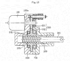
- an electric linear actuator employing a ball screw mechanism configured to convert a rotary motion of a motor into a motion in a linear direction.
- an electric linear actuator mainly including an electric motor 100, a ball screw 200, and a gear speed reduction mechanism 500.
- the gear speed reduction mechanism 500 is configured to transmit a rotary motion of the electric motor 100 to the ball screw 200.
- the ball screw 200 includes a screw shaft 201, a nut 202, and a large number of balls 203.
- the screw shaft 201 has a spiral screw groove formed in an outer peripheral surface.
- the nut 202 is externally fitted to the screw shaft 201, and has a spiral screw groove formed in an inner peripheral surface.
- the balls 203 are received in both of the screw grooves.
- the gear speed reduction mechanism 500 includes a first gear 501 and a second gear 502.
- the first gear 501 has a small diameter, and is fixed to a motor shaft 100a of the electric motor 100.
- the second gear 502 has a large diameter, is formed on an outer periphery of the nut 202, and meshes with the first gear 501.
- Patent Literature 1 JP 5243018 B2
- the present invention has been made in view of the above-mentioned problem, and therefore has an object to provide an electric actuator capable of achieving size reduction and increase in degree of freedom in design.
- an electric actuator comprising: a drive part; a motion conversion mechanism part configured to convert a rotary motion from the drive part to a linear motion in an axial direction parallel with an output shaft of the drive part; a driving force transmission part comprising a transmission gear mechanism configured to transmit a driving force from the drive part to the motion conversion mechanism part; and a motion-conversion-mechanism support part comprising a double-row bearing configured to support the motion conversion mechanism part, wherein the double-row bearing is arranged on one side in the axial direction with respect to the transmission gear mechanism.
- the double-row bearing is arranged on the opposite side of the drive part with respect to the transmission gear mechanism.
- the drive part can be arranged close to the motion conversion mechanism part in a direction orthogonal to the axial direction thereof on the side on which the double-row bearing is not arranged. With this, an axis-to-axis distance between the drive part and the motion conversion mechanism part can be reduced, and downsizing of the electric actuator can thus be attained.
- the double-row bearing comprise a double-row angular contact ball bearing.
- the double-row bearing can bear a radial load as well as axial loads in both directions, and can thus stably and reliably support the motion conversion mechanism part.
- the double-row angular contact ball bearing have a back-to-back configuration. This case is advantageous also with respect to a moment load.
- the electric actuator may comprise a stroke sensor configured to detect a stroke of the linear motion of the motion conversion mechanism part.
- the stroke sensor can be arranged on the opposite side of the double-row bearing with respect to the transmission gear mechanism, and the stroke sensor can thus be arranged without considering interference with the double-row bearing.
- the electric actuator may comprise a boot configured to prevent a foreign substance from entering the motion conversion mechanism part.
- the boot can be arranged on the opposite side of the double-row bearing with respect to the transmission gear mechanism, and the boot can thus be arranged without considering interference with the double-row bearing.
- the drive part may comprise a driving motor and a motor case configured to accommodate the driving motor.
- an outer peripheral surface of the motor case on a side of the motion conversion mechanism part is arranged at a position closer to the motion conversion mechanism part than a position of an imaginary plane of an extension in the axial direction of an outer peripheral surface of the double-row bearing.
- the electric actuator capable of achieving the size reduction and the increase in degree of freedom in design can be provided.
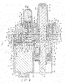
- FIG. 1 is a vertical sectional view for illustrating an assembled state of an electric actuator according to one embodiment of the present invention.
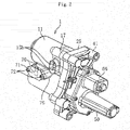
- FIG. 2 is an external perspective view for illustrating the assembled state of the electric actuator.
- FIG. 3 is an exploded perspective view of the electric actuator.
- an electric actuator 1 of this embodiment mainly comprises a drive part 2, a motion conversion mechanism part 3, a driving force transmission part 4, a motion-conversion-mechanism support part 5, an operation part 6, and a lock mechanism part 7.
- the drive part 2 is configured to generate a driving force.
- the motion conversion mechanism part 3 is configured to convert a rotary motion from the drive part 2 into a linear motion .
- the driving force transmission part 4 is configured to transmit the driving force from the drive part 2 to the motion conversion mechanism part 3.
- the motion-conversion-mechanism support part 5 is configured to support the motion conversion mechanism part 3.
- the operation part 6 is configured to output the motion of the motion conversion mechanism part 3.
- the lock mechanism part 7 is configured to prevent the motion conversion mechanism part 3 from driving.
- the drive part 2 comprises a motor part 8 and a speed reduction mechanism part 9.
- each of the parts forming the electric actuator 1 has a case. Component parts are accommodated in each of the cases.
- the motor part 8 comprises a motor case 11 configured to accommodate a driving motor 10.
- the speed reduction mechanism part 9 comprises a speed reduction gear case 17 configured to accommodate a speed reduction gear mechanism 16.
- the driving force transmission part 4 comprises a transmission gear case 29 configured to accommodate a transmission gear mechanism 28.
- the motion-conversion-mechanism support part 5 comprises a bearing case 41 configured to accommodate a support bearing 40.
- respective pairs of the motor part 8 and the speed reduction mechanism part 9, the speed reduction mechanism part 9 and the driving force transmission part 4, and the driving force transmission part 4 and the motion-conversion-mechanism support part 5 are configured to be capable of being coupled to and decoupled from one another while the pairs are accommodated in the cases.
- a shaft case 50 is configured to be capable of being coupled to and decoupled from the bearing case 41.
- the motor part 8 mainly comprises the driving motor (DC motor) 10 and the motor case 11.
- the driving motor 10 is configured to drive the motion conversion mechanism part 3.
- the motor case 11 is configured to accommodate the driving motor 10.
- the motor case 11 comprises a case main body 12 and a projecting portion 13.
- the case main body 12 has a bottomed cylindrical shape, and is configured to accommodate the driving motor 10 therein.
- the projecting portion 13 projects from a bottom portion 12a of the case main body 12 to the outside.
- the projecting portion 13 has a hole portion 13a which communicates to an internal space of the case main body 12.
- the hole portion 13a is sealed by a seal member 14 that is made of resin and covers an outer surface of the projecting portion 13.
- an inner peripheral surface of a peripheral wall portion 12b of the case main body 12 is reduced in diameter in a tapered shape from the opening portion 12d side toward the bottom portion 12a side.
- FIG. 4 which is a view of the motor case 11 as seen from the opening portion 12d side, a pair of bus bars 15 configured to connect the driving motor 10 to a power supply is mounted to the case main body 12.
- One end portion 15a of each of the bus bars 15 is connected to a motor terminal 10c through crimping, and another end portion 15b is exposed from the case main body 12 to the outside (see FIG. 2 and FIG. 3 ).
- the end portions 15b of the bus bars 15 exposed to the outside are connected to the power supply.
- the speed reduction mechanism part 9 mainly comprises the speed reduction gear mechanism 16 and the speed reduction gear case 17.
- the speed reduction gear mechanism 16 is configured to reduce the speed of the driving force of the driving motor 10 and output the driving force.
- the speed reduction gear case 17 is configured to accommodate the speed reduction gear mechanism 16.
- the speed reduction gear mechanism 16 is formed of a planetary-gear speed reduction mechanism 18 comprising a plurality of gears and the like. A detailed configuration of the planetary-gear speed reduction mechanism 18 is described later.
- the speed reduction gear case 17 has an accommodating recessed portion 17a configured to accommodate the planetary-gear speed reduction mechanism 18 from an opposite side of the driving motor 10. Moreover, the speed reduction gear case 17 is formed so as to enable a motor adaptor 19 serving as a motor mounting member to be mounted thereto.
- the motor adaptor 19 is a tubular member, and a projection 10d of the driving motor 10 on an output side (right side in FIG. 1 ) is inserted into and fitted to an inner peripheral surface of the motor adaptor 19.
- the speed reduction gear case 17 has a fitting hole 17b to which the motor adaptor 19 is fitted. The motor adaptor 19 is inserted from the driving motor 10 side into the fitting hole 17b and mounted to the fitting hole 17b.
- the speed reduction gear case 17 is configured to be capable of being fitted to the motor case 11 and the transmission gear case 29 described later and arranged on the opposite side of the motor case 11. A portion of the speed reduction gear case 17 arranged on the motor case 11 side is internally fitted to the opening portion 12d side of the motor case 11. A portion of the speed reduction gear case 17 arranged on the transmission gear case 29 side is externally fitted to the transmission gear case 29. Moreover, the speed reduction gear case 17 is fastened to the driving motor 10 through bolts 21 (see FIG. 3 and FIG. 6 ) together with the motor adaptor 19 while being fitted to the motor case 11.
- recessed portions 17c configured to prevent interference with the motor terminals 10c projecting from the driving motor 10 and with the end portions 15a of the bus bars 15 crimped to the motor terminals 10c while the speed reduction gear case 17 and the motor case 11 are fitted to each other.
- a mounting groove 17d configured to mount an O ring 20 is formed in an outer peripheral surface (fitting surface) of the speed reduction gear case 17 to be fitted to an inner peripheral surface of the motor case 11.
- the motion conversion mechanism part 3 is formed of a ball screw 22.
- the ball screw 22 mainly comprises a ball screw nut 23, a ball screw shaft 24, a large number of balls 25, and deflectors 26.
- the ball screw nut 23 serves as a rotary body.
- the ball screw shaft 24 is a shaft portion performing a linear motion.
- the deflectors 26 serve as circulation members. Spiral grooves 23a and 24a are respectively formed in an inner peripheral surface of the ball screw nut 23 and an outer peripheral surface of the ball screw shaft 24.
- the balls 25 are loaded between both of the spiral grooves 23a and 24a, and the deflectors 26 are assembled therebetween. With this configuration, the balls 25 in two rows circulate.
- FIG. 1 is a view for illustrating a state in which the ball screw shaft 24 is arranged at an initial position given when the ball screw shaft 24 retreats most to the right side of FIG. 1 .
- the ball screw shaft 24 is arranged in parallel with the output shaft 10a of the driving motor 10.
- the rotary motion from the driving motor 10 is converted into a linear motion in the axial direction parallel with the output shaft 10a by the ball screw shaft 24.
- a distal end portion (left end portion in FIG. 1 ) of the ball screw shaft 24 in an advancing direction functions as the operation part (actuator head) 6 configured to operate an object device to be operated
- the driving force transmission part 4 mainly comprises the transmission gear mechanism 28 and the transmission gear case 29.
- the transmission gear mechanism 28 is configured to transmit the driving force from the driving motor 10 of the drive part 2 to the ball screw 22 being the motion conversion mechanism part 3.
- the transmission gear case 29 is configured to accommodate the transmission gear mechanism 28.
- the transmission gear mechanism 28 comprises a drive gear 30 on a drive side and a driven gear 31 on a driven side meshing with the drive gear 30.
- a gear boss 32 is press-fitted to a rotation center portion of the drive gear 30.
- the drive gear 30 is rotatably supported through intermediation of the gear boss 32 by two rolling bearings 33 and 34 mounted to both the transmission gear case 29 and the bearing case 41 described later.
- the driven gear 31 is press-fitted and fixed to the outer peripheral surface of the ball screw nut 23.
- the transmission gear case 29 comprises an accommodating recessed portion 29a configured to accommodate the drive gear 30 and the driven gear 31 therein. Moreover, the transmission gear case 29 has an insertion hole 29b through which the gear boss 32 is inserted. On an inner peripheral surface of the insertion hole 29b, there is formed a bearing mounting surface 29c to which the one rolling bearing 33 configured to support the gear boss 32 is mounted. Moreover, the transmission gear case 29 comprises an annular projection 29d fitted to an inner peripheral surface of the speed reduction gear case 17. In an outer peripheral surface (fitting surface) of the annular projection 29d, there is formed a mounting groove 29e configured to mount an O ring 35. Moreover, in a surface of the transmission gear case 29 on the bearing case 41 side, there is formed a fitting recessed portion 29f in a groove form fitted to the bearing case 41.
- the transmission gear case 29 comprises a cylindrical portion 29g projecting toward a distal end portion side (left side in FIG. 1 ) of the ball screw shaft 24.
- the cylindrical portion 29g is a portion arranged so as to cover a periphery of the ball screw shaft 24 under a state in which the driven gear 31 is accommodated in the transmission gear case 29, and the ball screw 22 is assembled to the driven gear 31.
- a boot 36 configured to prevent foreign substances from entering the transmission gear case 29 is mounted between the cylindrical portion 29g and the ball screw shaft 24.
- the boot 36 comprises a large-diameter end portion 36a, a small-diameter end portion 36b, and a bellows portion 36c, which connects the large-diameter end portion 36a and the small-diameter end portion 36b to each other, and expands and contracts in the axial direction.
- the large-diameter end portion 36a is fixed to a mounting portion of an outer peripheral surface of the cylindrical portion 29g by tightening a boot band 37.
- the small-diameter end portion 36b is fixed to a mounting portion of the outer peripheral surface of the ball screw shaft 24 by tightening a boot band 38.
- the cylindrical portion 29g has a vent hole 29h which is configured to cause the air to communicate between an inside and an outside of the boot 36 when the boot 36 expands and contracts.
- a boot cover 39 arranged around the boot 36 is provided integrally with the motor case 11.
- the motion-conversion-mechanism support part 5 mainly comprises the support bearing 40 and the bearing case 41.
- the support bearing 40 is configured to support the ball screw 22 being the motion conversion mechanism part 3.
- the support bearing 40 is formed of a double-row angular contact ball bearing mainly comprising an outer ring 42, an inner ring 43, double-row balls 44, and a retainer (not shown) .
- the outer ring 42 has double-row raceway surfaces 42a formed on an inner peripheral surface.
- the inner ring 43 has double-row raceway surfaces 43a formed on an outer peripheral surface .
- the balls 44 are interposed between the raceway surfaces 42a and 43a.
- the retainer is configured to retain the balls 44.
- the support bearing 40 is accommodated in a sleeve 45 formed integrally with the bearing case 41, and is fixed through a snap ring 46 mounted to an inner peripheral surface of the sleeve 45. Moreover, the support bearing 40 is fixed by being press-fitted to an outer peripheral surface of the ball screw nut 23 on a rear end side (right side in FIG. 1 ) of the ball screw shaft 24 with respect to the driven gear 31. A movement in the axial direction of the support bearing 40 and the driven gear 31 fixed to the outer peripheral surface of the ball screw nut 23 is restricted by a restriction projection 23b formed on the ball screw nut 23 on the driven gear 31 side and a restriction member 47 mounted on the support bearing 40 side.
- the restriction member 47 comprises a pair of semicircular members, and is mounted to the outer peripheral surface of the ball screw nut 23 while the semicircular members are combined in an annular form. Further, a pressing collar 48 and a snap ring 49 are mounted to the outer peripheral surface of the ball screw nut 23.
- the pressing collar 48 is configured to hold the restriction member 47.
- the snap ring 49 is configured to prevent the pressing collar 48 from falling off in the axial direction.
- a protruding portion 41a configured to be fitted to the fitting recessed portion 29f of the transmission gear case 29.
- a gear boss accommodating portion 41b configured to accommodate a part of the gear boss 32 projecting from the transmission gear case 29 under a state in which the bearing case 41 is fitted to the transmission gear case 29.
- a bearing mounting surface 41c which is configured to mount the rolling bearing 34 configured to support the gear boss 32.
- the shaft case 50 On an opposite side of the bearing case 41 with respect to the transmission gear case 29 side, the shaft case 50 having a bottomed tubular shape configured to accommodate a rear end portion side (right end portion side in FIG. 1 ) of the ball screw shaft 24 is formed so as to be capable of being fastened through bolts 51 (see FIG. 3 ).
- a mounting groove 50a configured to mount an O ring 52.
- a guide collar 53 is rotatably mounted to each of the both end portions of the pin 27. When the ball screw shaft 24 advances and retreats in the axial direction, the guide collars 53 move along the guide grooves 50b while rotating.
- bolt insertion holes 11a, 17e, 29i, and 41d for inserting bolts 54 configured to assemble and fasten the motor case 11, the speed reduction gear case 17, the transmission gear case 29, and the bearing case 41 are formed in outer peripheries of the respective cases in a radial direction. Further, through holes 29j and 41e configured to mount the assembled electric actuator 1 to an installation location are formed in the outer peripheries in the radial direction of both of the transmission gear case 29 and the bearing case 41.
- FIG. 5 is a transverse sectional view as seen in a direction indicated by the arrows of the line A-A in FIG. 1 .
- FIG. 6 is an exploded perspective view of the planetary-gear speed reduction mechanism 18.
- the planetary-gear speed reduction mechanism 18 comprises a ring gear 55, a sun gear 56, a plurality of planetary gears 57, a planetary gear carrier 58 (see FIG. 1 ), and planetary gear holders 59 (see FIG. 1 ).
- the ring gear 55 comprises a plurality of protrusions 55a projecting in the axial direction. Engagement recessed portions 17f as many as the protrusions 55a are formed in the accommodating recessed portion 17a of the speed reduction gear case 17 (see FIG. 1 ).
- the ring gear 55 is accommodated in the speed reduction gear case 17 while the rotation of the ring gear 55 is stopped.
- the sun gear 56 is arranged at the center of the ring gear 55.
- the output shaft 10a of the driving motor 10 is press-fitted to the sun gear 56.
- the respective planetary gears 57 are arranged between the ring gear 55 and the sun gear 56 so as to mesh with the ring gear 55 and the sun gear 56.
- the respective planetary gears 57 are rotatably supported by the planetary gear carrier 58 and the planetary gear holders 59.
- the planetary gear carrier 58 comprises a cylindrical portion 58a at its center portion.
- the cylindrical portion 58a is press-fitted between an outer peripheral surface of the gear boss 32 and an inner peripheral surface of the rolling bearing 33 (see FIG. 1 ).
- An annular collar 75 is mounted between an inner peripheral surface of the another rolling bearing 34 and the outer peripheral surface of the gear boss 32.
- the sun gear 56 coupled to the output shaft 10a of the driving motor 10 rotates, and, along with this rotation, the respective planetary gears 57 revolve along the ring gear 55 while rotating. Then, the planetary gear carrier 58 is rotated by the revolving motion of the planetary gears 57. With this, the rotation of the driving motor 10 is reduced in speed and transmitted to the drive gear 30, and a rotation torque increases.
- the driving force is transmitted through the planetary-gear speed reduction mechanism 18 in such a manner, a high output of the ball screw shaft 24 can be obtained, and downsizing of the driving motor 10 can be attained.
- FIG. 7 is an exploded perspective view of the shaft case 50 and the lock mechanism part 7 mounted thereto.
- FIG. 8 is a transverse sectional view as seen in a direction indicated by the arrows of the line B-B in FIG. 1 .
- the lock mechanism part 7 mainly comprises a lock member 60, a sliding screw nut 61, a sliding screw shaft 62, a lock-member fixation plate 63, a locking motor (DC motor) 64, and a spring 65.
- the lock member 60 is fastened to the sliding screw nut 61 through intermediation of the lock-member fixation plate 63 with bolts 84 (see FIG. 7 ).
- the locking motor 64 is accommodated in a holder portion 66 formed in the shaft case 50.
- the sliding screw shaft 62 is then mounted to an output shaft 64a of the locking motor 64 projecting from the holder portion 66.
- the spring 65 is arranged on an outer periphery of the sliding screw shaft 62, and the sliding screw nut 61 having the lock member 60 mounted thereto is mounted to the sliding screw shaft 62 through thread engagement. In such a manner, the assembly of the lock mechanism part 7 is completed.
- the holder portion 66 is formed into a bottomed tubular shape, and a cap 67 is mounted on an opposite side of a bottom portion 66a thereof.
- the locking motor 64 is held in abutment against the bottom portion 66a of the holder portion 66 and an inner surface of the cap 67 under a state in which the locking motor 64 is inserted into the holder portion 66 and the cap 67 is mounted. Moreover, under this state, a projection 64b of the locking motor 64 on an output side (left side in FIG. 1 ) is fitted to a fitting hole 66c formed in the bottom portion 66a of the holder portion 66.
- Both of an outer peripheral surface of the main body of the locking motor 64 and an inner peripheral surface of a peripheral wall portion 66b of the holder portion 66 are formed into the same shapes, which are not cylindrical.
- the rotation of the locking motor 64 is restricted through the insertion of the locking motor 64 into the peripheral wall portion 66b of the holder portion 66.
- the cap 67 has a hole portion 67a configured to insert cables 68 connected to motor terminals 64d of the locking motor 64 (see FIG. 8 ).
- Lock-mechanism accommodating recessed portions 66d and 41f are respectively formed in a portion of the shaft case 50 at which the holder portion 66 is formed and a portion of the bearing case 41 opposed thereto.
- a through hole 41g is formed in the lock-mechanism accommodating recessed portion 41f on the bearing case 41 side. As illustrated in FIG.
- a part of the output shaft 64a of the locking motor 64, the sliding screw shaft 62, the sliding screw nut 61, the lock-member fixation plate 63, the spring 65, and the lock member 60, which project from the holder portion 66, are accommodated in the lock-mechanism accommodating recessed portions 66d and 41f, and a distal end portion side of the lock member 60 is inserted into the through hole 41g under a state in which the shaft case 50 is mounted to the bearing case 41.
- the spring 65 is compressed in the axial direction between the bottom portion 66a of the holder portion 66 and the lock-member fixation plate 63 under the state in which the shaft case 50 is mounted to the bearing case 41.
- the lock member 60 is always urged in an advancing direction (left side in FIG. 1 ) by the compressed spring 65.
- the drive gear 30 is arranged in the advancing direction of the lock member 60.
- the drive gear 30 has engagement holes 30a with which the distal end portion of the lock member 60 can be engaged.
- FIG. 9 which is a transverse sectional view as seen in a direction indicated by the arrows of the line C-C in FIG. 1
- the plurality of engagement holes 30a are formed in a circumferential direction of the drive gear 30.
- the rotation of the drive gear 30 is restricted through the engagement of the lock member 60 with any one of those engagement holes 30a.
- a tilted surface 30b is formed at an entrance portion of each of the engagement holes 30a, and the lock member 60 is thus smoothly inserted into the engagement hole 30a along the tilted surface 30b.
- a lock sensor 69 configured to detect a locking state is mounted to the bearing case 41 (see FIG. 8 ).
- the lock sensor 69 comprises a contact element 69a formed of an elastic member such as a plate spring.
- the lock member 60 advances to be engaged with the engagement hole 30a (brought into a locking state)
- the lock member 60 pushes the contact element 69a so that the lock sensor 69 detects the locking state.
- the lock member 60 When power is not supplied to the locking motor 64, the lock member 60 is held at the advanced position by the spring 65, and is in the locking state in which the distal end portion of the lock member 60 is engaged with the engagement hole 30a of the drive gear 30.
- the power is also supplied to the locking motor 64, and the locking motor 64 drives the lock member 60 in a retreating direction.
- the sliding screw shaft 62 rotates. Meanwhile, the rotation of the sliding screw nut 61 is restricted through the insertion of the flat-plate-shaped distal end portion of the lock member 60 into the through hole 41g.
- the ball screw shaft 24 is held in the state in which the ball screw shaft 24 does not retreat. With this, even when an external force is input from the object device to be operated to the ball screw shaft 24 side, a position of the ball screw shaft 24 can be held at a predetermined position.
- This configuration is particularly preferred for a case in which the electric actuator is applied to an application that requires holding a position of the ball screw shaft 24.
- the lock member 60 is caused to retreat by driving the locking motor 64.
- the locking motor 64 may be driven to cause the lockmember 60 to advance .
- the lock member 60 may be caused to advance and retreat by rotating the locking motor 64 forward and backward.
- a stroke sensor 70 configured to detect a stroke of the ball screw shaft 24 is mounted to the electric actuator 1 of this embodiment (see FIG. 2 and FIG. 3 ).
- the stroke sensor 70 is mounted to a sensor base 71.
- the sensor base 71 is fastened and fixed through bolts 72 to a sensor case 76 formed on an outer peripheral surface between the motor case 11 and the boot cover 39.
- a permanent magnet 73 serving as a sensor target is mounted to an outer peripheral surface of a portion of the ball screw shaft 24 covered with the boot 36 (see FIG. 1 ).
- the permanent magnet 73 is mounted to the ball screw shaft 24 through intermediation of a cylindrical elastic member 74 cut apart at a portion in a peripheral direction.
- a control signal is transmitted from a controller 81 of the control device 80 to the driving motor 10.
- the target value is, for example, a stroke value calculated by an ECU provided at an upper position of a vehicle based on an operation amount when the operation amount is input to the ECU.
- the driving motor 10 When the driving motor 10 receives the control signal, the driving motor 10 starts the rotational drive, and the driving force thereof is transmitted to the ball screw shaft 24 through intermediation of the planetary-gear speed reduction mechanism 18, the drive gear 30, the driven gear 31, and the ball screw nut 23, and the ball screw shaft 24 thus advances. With this, the object device to be operated arranged on the distal end portion side (actuator head side) of the ball screw shaft 24 is operated.
- the stroke value (position in the axial direction) of the ball screw shaft 24 is detected by the stroke sensor 70.
- the detection value detected by the stroke sensor 70 is transmitted to a comparison portion 82 of the control device 80, and a difference between the detection value and the target value is calculated. Then, the driving motor 10 is driven until the detection value matches the target value.
- a shift position can reliably be controlled by feeding back the stroke value detected by the stroke sensor 70 to control the position of the ball screw shaft 24 in such a manner.
- the pressure sensor 83 is provided for the object device to be operated.
- the ECU calculates a required target value (pressure command value) .
- the target value is transmitted to the control device 80, and the control signal is transmitted from the controller 81 to the driving motor 10, the driving motor 10 starts the rotational drive.
- the ball screw shaft 24 advances, and the object device to be operated arranged on the distal end portion side (actuator head side) of the ball screw shaft 24 is operated to pressurize.
- An operation pressure of the ball screw shaft 24 at this time is detected by the pressure sensor 83, and the position of the ball screw shaft 24 is subjected to the feedback control based on the detection value and the target value as in the case of the use of the stroke sensor 70.
- a hydraulic pressure of a brake can reliably be controlled by feeding back the pressure value detected by the pressure sensor 83 to control the position of the ball screw shaft 24 in such a manner.
- the support bearing 40 configured to support the ball screw 22 is arranged only on one side (right side) with respect to the driven gear 31, and any bearing configured to support the ball screw 22 is not arranged on an opposite side (left side) .
- the support bearing 40 only on the one side with respect to the driven gear 31 in such a manner, there is no need to consider interference between the support bearing 40 and other component parts on the side on which the support bearing 40 is not arranged. Accordingly, the degree of freedom in design of the component layout thus increases, and downsizing can also be attained.
- the drive part 2 can be arranged close to the ball screw 22 in a direction (radial direction) orthogonal to the axial direction thereof.
- the drive part 2 needs to be arranged at a position separated farther from the ball screw 22 in the radial direction than a position of a long dashed short dashed line ⁇ illustrated in FIG. 1 .
- the long dashed short dashed line ⁇ is a line indicating a position closest to the drive part 2 side out of an imaginary plane of an extension in the axial direction of the outer peripheral surface of the support bearing 40 illustrated in FIG. 1 , and is a position at which a portion of the outer peripheral surface of the support bearing 40 closest to the drive part 2 side is arranged when the support bearing 40 is arranged on the drive part 2 side.
- the support bearing 40 when the support bearing 40 is arranged on the opposite side of the drive part 2, the support bearing 40 is not present on the drive part 2 side. Therefore, an outer peripheral surface of the drive part 2 (motor case 11) on the ball screw 22 side can be arranged closer to the ball screw 22 than the position indicated by the long dashed short dashed line ⁇ in the radial direction. With this, the axis-to-axis distance between the driving motor 10 and the ball screw shaft 24 is reduced, and downsizing of the electric actuator 1 in the vertical direction can be attained. Moreover, the support bearing 40 is not arranged on the drive part 2 side. Thus, as in this embodiment, a space not used for the arrangement may be used to arrange the boot 36, the boot cover 39, the cylindrical portion 29g to which the boot 36 is mounted, the stroke sensor 70, the permanent magnet 73 serving as the target, and the like.
- the double-row angular contact ball bearing is used as the support bearing 40.
- Any of the balls 44 in the double rows are in contact with the raceway surfaces 42a of the outer ring 42 and the raceway surfaces 43a of the inner ring 43 at contact angles, and the double-row angular contact ball bearing can thus bear a radial load as well as axial loads in the both directions, and can stably and reliably support the ball screw 22 performing the linear motion.
- the contact angle is an angle formed between a plane (radial plane) perpendicular to a center axis of the bearing and a line of action (long dashed short dashed line passing through the center of each of the balls 44 illustrated in FIG.
- a preload does not act on the balls 44, and gaps between the respective raceway surfaces 42a and 43a of the outer ring 42 and the inner ring 43 and the balls 44 are positive gaps. Moreover, conversely, a preload may be applied to the balls 44, thereby forming negative gaps.
- FIG. 12 is an illustration of the electric actuator 1 according to another embodiment of the present invention.
- the electric actuator 1 illustrated in FIG. 12 is configured, compared with the electric actuator 1 illustrated in FIG. 1 , by eliminating the speed reduction mechanism part 9, directly coupling the motor part 8 and the driving force transmission part 4 to each other, and replacing the shaft case 50 by one without the holder portion 66 to which the lock mechanism part 7 is mounted. In this case, the speed reduction mechanism part 9 is not provided.
- the output shaft 10a of the driving motor 10 is press-fitted to the gear boss 32, and the rolling bearing 33 on the transmission gear case 29 side configured to support the gear boss 32 is omitted.
- a member to be fitted to the motor adaptor 19, to which the driving motor 10 is mounted is changed from the speed reduction gear case 17 to the transmission gear case 29, and is thus replaced by one having a different shape conforming to a fitting shape of the member to be fitted to the motor adaptor 19.
- the other configurations are the same as those of the embodiment illustrated in FIG. 1 .
- the electric actuator 1 of the embodiment illustrated in FIG. 12 is controlled to operate basically in the same manner as in the embodiment illustrated in FIG. 1 except that the driving force from the driving motor 10 is directly transmitted to the driving force transmission part 4 without intermediation of the speed reduction mechanism part 9. Thus, description of the control and the operation is omitted.
- the support bearing 40 is arranged only on one side with respect to the driven gear 31. Therefore, the degree of freedom in design thus increases, and downsizing can be attained. Moreover, through use of a back-to-back double-row angular contact ball bearing as the support bearing 40, the ball screw 22 can stably and reliably be supported, and the configuration which is advantageous with respect to the moment load can be achieved.
- the size reduction and the increase in degree of freedom in design of the electric actuator can be achieved.
- the design of the electric actuator can be easily changed in accordance with various applications and usages.
- the configuration of the electric actuator according to one embodiment of the present invention is preferred for series production and multiple-type deployment of the electric actuator adapted to applications and usages such as an electric parking brake mechanism for vehicles including two-wheeled vehicles, an electric/hydraulic brake mechanism, an electric shift change mechanism, and an electric power steering as well as a 2WD/4WD electric switching mechanism and an electric shift change mechanism for an outboard engine (for a vessel propulsion engine).
- the support bearing 40 is not limited to this type of bearing, and a pair of single-row angular contact ball bearings may be used in combination.
- the support bearing 40 in addition to the angular contact ball bearing, another double-row bearing using, for example, a deep groove ball bearing may be applied. Even in the case in which such a double-row bearing is used, the increase in degree of freedom in design and downsizing can be attained thorough the support of the ball screw 22 by the double-row bearing on the one side with respect to the driven gear 31 as in the case described above .
- the support bearing 40 may be formed so that the outer ring 42 is formed integrally with the bearing case 41, or the inner ring 43 is formed integrally with the ball screw nut 23.
- the motion conversion mechanism part 3 is not limited to the ball screw 22, and may be a sliding screw device.
- the ball screw 22 is more preferred in terms of reducing the rotation torque and downsizing the driving motor 10.
- the speed reduction mechanism part 9 may be a speed reduction mechanism other than the planetary-gear speed reduction mechanism 18. Moreover, the rotational drive may be transmitted at a constant speed or transmitted at a reduced speed between the drive gear 30 and the driven gear 31.
Landscapes
- Engineering & Computer Science (AREA)
- General Engineering & Computer Science (AREA)
- Mechanical Engineering (AREA)
- Power Engineering (AREA)
- Connection Of Motors, Electrical Generators, Mechanical Devices, And The Like (AREA)
- Transmission Devices (AREA)
- Chemical & Material Sciences (AREA)
- Combustion & Propulsion (AREA)
- Transportation (AREA)
Abstract
Description
- The present invention relates to an electric actuator.
- In recent years, electrification of automobiles and the like has been promoted for power saving and reduction in fuel consumption. For example, a system for operating an automatic transmission, a brake, a steering wheel, and the like of the automobile with use of power of an electric motor has been developed and brought to the market. As an electric actuator for use in such an application, there has been known an electric linear actuator employing a ball screw mechanism configured to convert a rotary motion of a motor into a motion in a linear direction.
- For example, as illustrated in
FIG. 13 , inPatent Literature 1, there is disclosed an electric linear actuator mainly including anelectric motor 100, aball screw 200, and a gearspeed reduction mechanism 500. The gearspeed reduction mechanism 500 is configured to transmit a rotary motion of theelectric motor 100 to theball screw 200. Theball screw 200 includes ascrew shaft 201, anut 202, and a large number ofballs 203. Thescrew shaft 201 has a spiral screw groove formed in an outer peripheral surface. Thenut 202 is externally fitted to thescrew shaft 201, and has a spiral screw groove formed in an inner peripheral surface. Theballs 203 are received in both of the screw grooves. The gearspeed reduction mechanism 500 includes afirst gear 501 and asecond gear 502. Thefirst gear 501 has a small diameter, and is fixed to amotor shaft 100a of theelectric motor 100. Thesecond gear 502 has a large diameter, is formed on an outer periphery of thenut 202, and meshes with thefirst gear 501. When a driving force of theelectric motor 100 is transmitted to thenut 202 thorough intermediation of thegears nut 202 rotates, and thescrew shaft 201 performs a linear motion. - Patent Literature 1:
JP 5243018 B2 - Incidentally, in the electric linear actuator disclosed in
Patent Literature 1, in order to support thenut 202, tworolling bearings nut 202 while sandwiching thesecond gear 502. However, in the case in which therolling bearings ball screw 200, such a restriction in terms of layout that interference with the respective rolling bearing 600 and 700 needs to be prevented on the both sides of thesecond gear 502 is imposed, which may pose a problem in size reduction or design change. - The present invention has been made in view of the above-mentioned problem, and therefore has an object to provide an electric actuator capable of achieving size reduction and increase in degree of freedom in design.
- As a technical measure to attain the above-mentioned object, according to one embodiment of the present invention, there is provided an electric actuator, comprising: a drive part; a motion conversion mechanism part configured to convert a rotary motion from the drive part to a linear motion in an axial direction parallel with an output shaft of the drive part; a driving force transmission part comprising a transmission gear mechanism configured to transmit a driving force from the drive part to the motion conversion mechanism part; and a motion-conversion-mechanism support part comprising a double-row bearing configured to support the motion conversion mechanism part, wherein the double-row bearing is arranged on one side in the axial direction with respect to the transmission gear mechanism.
- Through the arrangement of the double-row bearing on the one side with respect to the transmission gear mechanism in the axial direction in such a manner, there is no need to consider interference between the double-row bearing and other component parts on the side on which the double-row bearing is not arranged. Accordingly, the degree of freedom in design of the component layout thus increases, and the downsizing can also be attained.
- Further, the double-row bearing is arranged on the opposite side of the drive part with respect to the transmission gear mechanism. Thus, the drive part can be arranged close to the motion conversion mechanism part in a direction orthogonal to the axial direction thereof on the side on which the double-row bearing is not arranged. With this, an axis-to-axis distance between the drive part and the motion conversion mechanism part can be reduced, and downsizing of the electric actuator can thus be attained.
- It is desired that the double-row bearing comprise a double-row angular contact ball bearing. In this case, the double-row bearing can bear a radial load as well as axial loads in both directions, and can thus stably and reliably support the motion conversion mechanism part.
- Further, it is desired that the double-row angular contact ball bearing have a back-to-back configuration. This case is advantageous also with respect to a moment load.
- Moreover, the electric actuator may comprise a stroke sensor configured to detect a stroke of the linear motion of the motion conversion mechanism part. In this case, the stroke sensor can be arranged on the opposite side of the double-row bearing with respect to the transmission gear mechanism, and the stroke sensor can thus be arranged without considering interference with the double-row bearing.
- Moreover, the electric actuator may comprise a boot configured to prevent a foreign substance from entering the motion conversion mechanism part. In this case, the boot can be arranged on the opposite side of the double-row bearing with respect to the transmission gear mechanism, and the boot can thus be arranged without considering interference with the double-row bearing.
- The drive part may comprise a driving motor and a motor case configured to accommodate the driving motor. In this case, an outer peripheral surface of the motor case on a side of the motion conversion mechanism part is arranged at a position closer to the motion conversion mechanism part than a position of an imaginary plane of an extension in the axial direction of an outer peripheral surface of the double-row bearing. Thus, an axis-to-axis distance between the driving motor and the motion conversion mechanism part can be reduced, and downsizing of the electric actuator can thus be attained.
- According to one embodiment of the present invention, the electric actuator capable of achieving the size reduction and the increase in degree of freedom in design can be provided.
-
-
FIG. 1 is a vertical sectional view of an electric actuator according to one embodiment of the present invention. -
FIG. 2 is an external perspective view of the electric actuator. -
FIG. 3 is an exploded perspective view of the electric actuator . -
FIG. 4 is a view of a motor case as seen from an opening portion side. -
FIG. 5 is a transverse sectional view as seen in a direction indicated by the arrows of the line A-A inFIG. 1 . -
FIG. 6 is an exploded perspective view of a speed reduction mechanism part. -
FIG. 7 is an exploded perspective view of a shaft case and a lock mechanism part mounted thereto. -
FIG. 8 is a transverse sectional view as seen in a direction indicated by the arrows of the line B-B inFIG. 1 . -
FIG. 9 is a transverse sectional view as seen in a direction indicated by the arrows of the line C-C inFIG. 1 . -
FIG. 10 is a control block diagram of the electric actuator. -
FIG. 11 is a control block diagram of the electric actuator. -
FIG. 12 is a vertical sectional view of the electric actuator according to another embodiment of the present invention. -
FIG. 13 is a vertical sectional view of a related-art electric linear actuator. - Now, description is made of the present invention with reference to the accompanying drawings. In the respective drawings for illustrating the present invention, components such as members and component parts having the same functions or shapes are denoted by the same reference symbols as long as the components can be distinguished, and description thereof is therefore omitted after the description is made once.
-
FIG. 1 is a vertical sectional view for illustrating an assembled state of an electric actuator according to one embodiment of the present invention.FIG. 2 is an external perspective view for illustrating the assembled state of the electric actuator.FIG. 3 is an exploded perspective view of the electric actuator. - As illustrated in
FIG. 1 , anelectric actuator 1 of this embodiment mainly comprises adrive part 2, a motionconversion mechanism part 3, a drivingforce transmission part 4, a motion-conversion-mechanism supportpart 5, anoperation part 6, and alock mechanism part 7. Thedrive part 2 is configured to generate a driving force. The motionconversion mechanism part 3 is configured to convert a rotary motion from thedrive part 2 into a linear motion . The drivingforce transmission part 4 is configured to transmit the driving force from thedrive part 2 to the motionconversion mechanism part 3. The motion-conversion-mechanism support part 5 is configured to support the motionconversion mechanism part 3. Theoperation part 6 is configured to output the motion of the motionconversion mechanism part 3. Thelock mechanism part 7 is configured to prevent the motionconversion mechanism part 3 from driving. Moreover, thedrive part 2 comprises amotor part 8 and a speedreduction mechanism part 9. - Each of the parts forming the
electric actuator 1 has a case. Component parts are accommodated in each of the cases. Specifically, themotor part 8 comprises amotor case 11 configured to accommodate a drivingmotor 10. The speedreduction mechanism part 9 comprises a speedreduction gear case 17 configured to accommodate a speedreduction gear mechanism 16. Moreover, the drivingforce transmission part 4 comprises atransmission gear case 29 configured to accommodate atransmission gear mechanism 28. The motion-conversion-mechanism support part 5 comprises a bearingcase 41 configured to accommodate asupport bearing 40. Further, respective pairs of themotor part 8 and the speedreduction mechanism part 9, the speedreduction mechanism part 9 and the drivingforce transmission part 4, and the drivingforce transmission part 4 and the motion-conversion-mechanism support part 5 are configured to be capable of being coupled to and decoupled from one another while the pairs are accommodated in the cases. Further, ashaft case 50 is configured to be capable of being coupled to and decoupled from the bearingcase 41. Now, description is made of detailed configurations of the respective parts forming theelectric actuator 1. - The
motor part 8 mainly comprises the driving motor (DC motor) 10 and themotor case 11. The drivingmotor 10 is configured to drive the motionconversion mechanism part 3. Themotor case 11 is configured to accommodate the drivingmotor 10. Themotor case 11 comprises a casemain body 12 and a projectingportion 13. The casemain body 12 has a bottomed cylindrical shape, and is configured to accommodate the drivingmotor 10 therein. The projectingportion 13 projects from abottom portion 12a of the casemain body 12 to the outside. The projectingportion 13 has ahole portion 13a which communicates to an internal space of the casemain body 12. Thehole portion 13a is sealed by aseal member 14 that is made of resin and covers an outer surface of the projectingportion 13. - Under a state in which the driving
motor 10 is inserted from anopening portion 12d of the casemain body 12 into an inside of the casemain body 12, an end surface of the drivingmotor 10 on an inner side in an insertion direction is held in abutment against thebottom portion 12a of the casemain body 12. Moreover, afitting hole 12c is formed in a center portion of thebottom portion 12a. Aprojection 10b of the drivingmotor 10 in the inner side in the insertion direction is fitted to thefitting hole 12c, thereby preventing interference of a rear end (left end portion inFIG. 1 ) of anoutput shaft 10a projecting from theprojection 10b with thebottom portion 12a of themotor case 11. Further, an inner peripheral surface of aperipheral wall portion 12b of the casemain body 12 is reduced in diameter in a tapered shape from theopening portion 12d side toward thebottom portion 12a side. When the drivingmotor 10 is inserted into the casemain body 12, an outer peripheral surface of the drivingmotor 10 on the inner side in the insertion direction comes into contact with the inner peripheral surface of theperipheral wall portion 12b. With this configuration, the drivingmotor 10 is supported through the contact with the inner peripheral surface of the casemain body 12 and the fitting to thefitting hole 12c under the state in which the drivingmotor 10 is inserted into the casemain body 12. - Moreover, as illustrated in
FIG. 4 , which is a view of themotor case 11 as seen from theopening portion 12d side, a pair ofbus bars 15 configured to connect the drivingmotor 10 to a power supply is mounted to the casemain body 12. Oneend portion 15a of each of the bus bars 15 is connected to amotor terminal 10c through crimping, and anotherend portion 15b is exposed from the casemain body 12 to the outside (seeFIG. 2 andFIG. 3 ). Theend portions 15b of the bus bars 15 exposed to the outside are connected to the power supply. - Next, description is made of the speed
reduction mechanism part 9. - As illustrated in
FIG. 1 , the speedreduction mechanism part 9 mainly comprises the speedreduction gear mechanism 16 and the speedreduction gear case 17. The speedreduction gear mechanism 16 is configured to reduce the speed of the driving force of the drivingmotor 10 and output the driving force. The speedreduction gear case 17 is configured to accommodate the speedreduction gear mechanism 16. The speedreduction gear mechanism 16 is formed of a planetary-gearspeed reduction mechanism 18 comprising a plurality of gears and the like. A detailed configuration of the planetary-gearspeed reduction mechanism 18 is described later. - The speed
reduction gear case 17 has an accommodating recessed portion 17a configured to accommodate the planetary-gearspeed reduction mechanism 18 from an opposite side of the drivingmotor 10. Moreover, the speedreduction gear case 17 is formed so as to enable amotor adaptor 19 serving as a motor mounting member to be mounted thereto. Themotor adaptor 19 is a tubular member, and aprojection 10d of the drivingmotor 10 on an output side (right side inFIG. 1 ) is inserted into and fitted to an inner peripheral surface of themotor adaptor 19. The speedreduction gear case 17 has afitting hole 17b to which themotor adaptor 19 is fitted. Themotor adaptor 19 is inserted from the drivingmotor 10 side into thefitting hole 17b and mounted to thefitting hole 17b. - The speed
reduction gear case 17 is configured to be capable of being fitted to themotor case 11 and thetransmission gear case 29 described later and arranged on the opposite side of themotor case 11. A portion of the speedreduction gear case 17 arranged on themotor case 11 side is internally fitted to theopening portion 12d side of themotor case 11. A portion of the speedreduction gear case 17 arranged on thetransmission gear case 29 side is externally fitted to thetransmission gear case 29. Moreover, the speedreduction gear case 17 is fastened to the drivingmotor 10 through bolts 21 (seeFIG. 3 andFIG. 6 ) together with themotor adaptor 19 while being fitted to themotor case 11. On the drivingmotor 10 side of the speedreduction gear case 17, there are formed recessedportions 17c configured to prevent interference with themotor terminals 10c projecting from the drivingmotor 10 and with theend portions 15a of the bus bars 15 crimped to themotor terminals 10c while the speedreduction gear case 17 and themotor case 11 are fitted to each other. Moreover, a mountinggroove 17d configured to mount anO ring 20 is formed in an outer peripheral surface (fitting surface) of the speedreduction gear case 17 to be fitted to an inner peripheral surface of themotor case 11. - Next, description is made of the motion
conversion mechanism part 3. - The motion
conversion mechanism part 3 is formed of aball screw 22. The ball screw 22 mainly comprises aball screw nut 23, aball screw shaft 24, a large number ofballs 25, anddeflectors 26. The ball screwnut 23 serves as a rotary body. The ball screwshaft 24 is a shaft portion performing a linear motion. Thedeflectors 26 serve as circulation members.Spiral grooves ball screw nut 23 and an outer peripheral surface of theball screw shaft 24. Theballs 25 are loaded between both of thespiral grooves deflectors 26 are assembled therebetween. With this configuration, theballs 25 in two rows circulate. - The ball screw
nut 23 receives the driving force from the drivingmotor 10, to thereby rotate in a forward direction or a backward direction. Meanwhile, the rotation of theball screw shaft 24 is restricted by apin 27 that is provided on a rear end portion (right end portion inFIG. 1 ) thereof and serves as a rotation restriction member. Therefore, when theball screw nut 23 rotates, theballs 25 circulate along both thespiral grooves deflectors 26, and theball screw shaft 24 advances and retreats in the axial direction.FIG. 1 is a view for illustrating a state in which theball screw shaft 24 is arranged at an initial position given when theball screw shaft 24 retreats most to the right side ofFIG. 1 . Moreover, theball screw shaft 24 is arranged in parallel with theoutput shaft 10a of the drivingmotor 10. The rotary motion from the drivingmotor 10 is converted into a linear motion in the axial direction parallel with theoutput shaft 10a by theball screw shaft 24. A distal end portion (left end portion inFIG. 1 ) of theball screw shaft 24 in an advancing direction functions as the operation part (actuator head) 6 configured to operate an object device to be operated - Next, description is made of the driving
force transmission part 4. - The driving
force transmission part 4 mainly comprises thetransmission gear mechanism 28 and thetransmission gear case 29. Thetransmission gear mechanism 28 is configured to transmit the driving force from the drivingmotor 10 of thedrive part 2 to theball screw 22 being the motionconversion mechanism part 3. Thetransmission gear case 29 is configured to accommodate thetransmission gear mechanism 28. Thetransmission gear mechanism 28 comprises adrive gear 30 on a drive side and a drivengear 31 on a driven side meshing with thedrive gear 30. - A
gear boss 32 is press-fitted to a rotation center portion of thedrive gear 30. Thedrive gear 30 is rotatably supported through intermediation of thegear boss 32 by two rollingbearings transmission gear case 29 and the bearingcase 41 described later. Meanwhile, the drivengear 31 is press-fitted and fixed to the outer peripheral surface of theball screw nut 23. When the driving force from the drivingmotor 10 is transmitted to thedrive gear 30 through intermediation of the planetary-gearspeed reduction mechanism 18, the drivengear 31 and theball screw nut 23 integrally rotate, and theball screw shaft 24 advances and retreats. - The
transmission gear case 29 comprises an accommodating recessedportion 29a configured to accommodate thedrive gear 30 and the drivengear 31 therein. Moreover, thetransmission gear case 29 has aninsertion hole 29b through which thegear boss 32 is inserted. On an inner peripheral surface of theinsertion hole 29b, there is formed abearing mounting surface 29c to which the one rollingbearing 33 configured to support thegear boss 32 is mounted. Moreover, thetransmission gear case 29 comprises anannular projection 29d fitted to an inner peripheral surface of the speedreduction gear case 17. In an outer peripheral surface (fitting surface) of theannular projection 29d, there is formed a mountinggroove 29e configured to mount anO ring 35. Moreover, in a surface of thetransmission gear case 29 on the bearingcase 41 side, there is formed a fitting recessed portion 29f in a groove form fitted to the bearingcase 41. - Moreover, the
transmission gear case 29 comprises a cylindrical portion 29g projecting toward a distal end portion side (left side inFIG. 1 ) of theball screw shaft 24. The cylindrical portion 29g is a portion arranged so as to cover a periphery of theball screw shaft 24 under a state in which the drivengear 31 is accommodated in thetransmission gear case 29, and theball screw 22 is assembled to the drivengear 31. Aboot 36 configured to prevent foreign substances from entering thetransmission gear case 29 is mounted between the cylindrical portion 29g and theball screw shaft 24. Theboot 36 comprises a large-diameter end portion 36a, a small-diameter end portion 36b, and abellows portion 36c, which connects the large-diameter end portion 36a and the small-diameter end portion 36b to each other, and expands and contracts in the axial direction. The large-diameter end portion 36a is fixed to a mounting portion of an outer peripheral surface of the cylindrical portion 29g by tightening aboot band 37. The small-diameter end portion 36b is fixed to a mounting portion of the outer peripheral surface of theball screw shaft 24 by tightening aboot band 38. Moreover, the cylindrical portion 29g has avent hole 29h which is configured to cause the air to communicate between an inside and an outside of theboot 36 when theboot 36 expands and contracts. Moreover, aboot cover 39 arranged around theboot 36 is provided integrally with themotor case 11. - Next, description is made of the motion-conversion-
mechanism support part 5. - The motion-conversion-
mechanism support part 5 mainly comprises the support bearing 40 and the bearingcase 41. Thesupport bearing 40 is configured to support theball screw 22 being the motionconversion mechanism part 3. Thesupport bearing 40 is formed of a double-row angular contact ball bearing mainly comprising anouter ring 42, aninner ring 43, double-row balls 44, and a retainer (not shown) . Theouter ring 42 has double-row raceway surfaces 42a formed on an inner peripheral surface. Theinner ring 43 has double-row raceway surfaces 43a formed on an outer peripheral surface . Theballs 44 are interposed between the raceway surfaces 42a and 43a. The retainer is configured to retain theballs 44. - The
support bearing 40 is accommodated in asleeve 45 formed integrally with the bearingcase 41, and is fixed through asnap ring 46 mounted to an inner peripheral surface of thesleeve 45. Moreover, the support bearing 40 is fixed by being press-fitted to an outer peripheral surface of theball screw nut 23 on a rear end side (right side inFIG. 1 ) of theball screw shaft 24 with respect to the drivengear 31. A movement in the axial direction of the support bearing 40 and the drivengear 31 fixed to the outer peripheral surface of theball screw nut 23 is restricted by arestriction projection 23b formed on theball screw nut 23 on the drivengear 31 side and arestriction member 47 mounted on the support bearing 40 side. Therestriction member 47 comprises a pair of semicircular members, and is mounted to the outer peripheral surface of theball screw nut 23 while the semicircular members are combined in an annular form. Further, apressing collar 48 and asnap ring 49 are mounted to the outer peripheral surface of theball screw nut 23. Thepressing collar 48 is configured to hold therestriction member 47. Thesnap ring 49 is configured to prevent thepressing collar 48 from falling off in the axial direction. - On the
transmission gear case 29 side of the bearingcase 41, there is formed a protrudingportion 41a configured to be fitted to the fitting recessed portion 29f of thetransmission gear case 29. Moreover, on thetransmission gear case 29 side of the bearingcase 41, there is formed a gearboss accommodating portion 41b configured to accommodate a part of thegear boss 32 projecting from thetransmission gear case 29 under a state in which thebearing case 41 is fitted to thetransmission gear case 29. On an inner peripheral surface of the gearboss accommodating portion 41b, there is formed abearing mounting surface 41c which is configured to mount the rollingbearing 34 configured to support thegear boss 32. - On an opposite side of the bearing
case 41 with respect to thetransmission gear case 29 side, theshaft case 50 having a bottomed tubular shape configured to accommodate a rear end portion side (right end portion side inFIG. 1 ) of theball screw shaft 24 is formed so as to be capable of being fastened through bolts 51 (seeFIG. 3 ). In an abutment surface of theshaft case 50 against the bearingcase 41, there is formed a mountinggroove 50a configured to mount anO ring 52. Moreover, in an inner peripheral surface of theshaft case 50, guidegrooves 50b into which both end portions of thepin 27 provided on theball screw shaft 24 are formed so as to extend in the axial direction. Aguide collar 53 is rotatably mounted to each of the both end portions of thepin 27. When theball screw shaft 24 advances and retreats in the axial direction, theguide collars 53 move along theguide grooves 50b while rotating. - As illustrated in
FIG. 3 ,bolt insertion holes bolts 54 configured to assemble and fasten themotor case 11, the speedreduction gear case 17, thetransmission gear case 29, and the bearingcase 41 are formed in outer peripheries of the respective cases in a radial direction. Further, throughholes electric actuator 1 to an installation location are formed in the outer peripheries in the radial direction of both of thetransmission gear case 29 and the bearingcase 41. - Now, description is made of the planetary-gear
speed reduction mechanism 18 with reference toFIG. 1 ,FIG. 5 , andFIG. 6 . -
FIG. 5 is a transverse sectional view as seen in a direction indicated by the arrows of the line A-A inFIG. 1 .FIG. 6 is an exploded perspective view of the planetary-gearspeed reduction mechanism 18. - The planetary-gear
speed reduction mechanism 18 comprises aring gear 55, asun gear 56, a plurality ofplanetary gears 57, a planetary gear carrier 58 (seeFIG. 1 ), and planetary gear holders 59 (seeFIG. 1 ). Thering gear 55 comprises a plurality ofprotrusions 55a projecting in the axial direction. Engagement recessed portions 17f as many as theprotrusions 55a are formed in the accommodating recessed portion 17a of the speed reduction gear case 17 (seeFIG. 1 ). Through assembly of theprotrusions 55a of thering gear 55 to the engagement recessed portions 17f of the speedreduction gear case 17 while theprotrusions 55a and the engagement recessed portions 17f are in phase, thering gear 55 is accommodated in the speedreduction gear case 17 while the rotation of thering gear 55 is stopped. - The
sun gear 56 is arranged at the center of thering gear 55. Theoutput shaft 10a of the drivingmotor 10 is press-fitted to thesun gear 56. Moreover, the respectiveplanetary gears 57 are arranged between thering gear 55 and thesun gear 56 so as to mesh with thering gear 55 and thesun gear 56. The respectiveplanetary gears 57 are rotatably supported by theplanetary gear carrier 58 and the planetary gear holders 59. Theplanetary gear carrier 58 comprises a cylindrical portion 58a at its center portion. The cylindrical portion 58a is press-fitted between an outer peripheral surface of thegear boss 32 and an inner peripheral surface of the rolling bearing 33 (seeFIG. 1 ). Anannular collar 75 is mounted between an inner peripheral surface of the another rollingbearing 34 and the outer peripheral surface of thegear boss 32. - In the planetary-gear
speed reduction mechanism 18 having the configuration described above, when the drivingmotor 10 performs the rotational drive, thesun gear 56 coupled to theoutput shaft 10a of the drivingmotor 10 rotates, and, along with this rotation, the respectiveplanetary gears 57 revolve along thering gear 55 while rotating. Then, theplanetary gear carrier 58 is rotated by the revolving motion of the planetary gears 57. With this, the rotation of the drivingmotor 10 is reduced in speed and transmitted to thedrive gear 30, and a rotation torque increases. When the driving force is transmitted through the planetary-gearspeed reduction mechanism 18 in such a manner, a high output of theball screw shaft 24 can be obtained, and downsizing of the drivingmotor 10 can be attained. - Next, description is made of the
lock mechanism part 7 with reference toFIG. 1 ,FIG. 7 , andFIG. 8 .FIG. 7 is an exploded perspective view of theshaft case 50 and thelock mechanism part 7 mounted thereto.FIG. 8 is a transverse sectional view as seen in a direction indicated by the arrows of the line B-B inFIG. 1 . - The
lock mechanism part 7 mainly comprises alock member 60, a slidingscrew nut 61, a slidingscrew shaft 62, a lock-member fixation plate 63, a locking motor (DC motor) 64, and aspring 65. When thelock mechanism part 7 is to be assembled, first, thelock member 60 is fastened to the slidingscrew nut 61 through intermediation of the lock-member fixation plate 63 with bolts 84 (seeFIG. 7 ). Next, the lockingmotor 64 is accommodated in aholder portion 66 formed in theshaft case 50. The slidingscrew shaft 62 is then mounted to anoutput shaft 64a of the lockingmotor 64 projecting from theholder portion 66. Then, thespring 65 is arranged on an outer periphery of the slidingscrew shaft 62, and the slidingscrew nut 61 having thelock member 60 mounted thereto is mounted to the slidingscrew shaft 62 through thread engagement. In such a manner, the assembly of thelock mechanism part 7 is completed. - The
holder portion 66 is formed into a bottomed tubular shape, and acap 67 is mounted on an opposite side of abottom portion 66a thereof. The lockingmotor 64 is held in abutment against thebottom portion 66a of theholder portion 66 and an inner surface of thecap 67 under a state in which the lockingmotor 64 is inserted into theholder portion 66 and thecap 67 is mounted. Moreover, under this state, aprojection 64b of the lockingmotor 64 on an output side (left side inFIG. 1 ) is fitted to afitting hole 66c formed in thebottom portion 66a of theholder portion 66. Both of an outer peripheral surface of the main body of the lockingmotor 64 and an inner peripheral surface of aperipheral wall portion 66b of theholder portion 66 are formed into the same shapes, which are not cylindrical. Thus, the rotation of the lockingmotor 64 is restricted through the insertion of the lockingmotor 64 into theperipheral wall portion 66b of theholder portion 66. Through accommodation of the lockingmotor 64 in theholder portion 66 in such a manner, the lockingmotor 64 is held by theholder portion 66, and the entirelock mechanism part 7 is held. Moreover, thecap 67 has ahole portion 67a configured to insertcables 68 connected tomotor terminals 64d of the locking motor 64 (seeFIG. 8 ). - Lock-mechanism accommodating recessed
portions shaft case 50 at which theholder portion 66 is formed and a portion of the bearingcase 41 opposed thereto. A throughhole 41g is formed in the lock-mechanism accommodating recessedportion 41f on the bearingcase 41 side. As illustrated inFIG. 1 , a part of theoutput shaft 64a of the lockingmotor 64, the slidingscrew shaft 62, the slidingscrew nut 61, the lock-member fixation plate 63, thespring 65, and thelock member 60, which project from theholder portion 66, are accommodated in the lock-mechanism accommodating recessedportions lock member 60 is inserted into the throughhole 41g under a state in which theshaft case 50 is mounted to the bearingcase 41. Moreover, thespring 65 is compressed in the axial direction between thebottom portion 66a of theholder portion 66 and the lock-member fixation plate 63 under the state in which theshaft case 50 is mounted to the bearingcase 41. Thelock member 60 is always urged in an advancing direction (left side inFIG. 1 ) by thecompressed spring 65. - The
drive gear 30 is arranged in the advancing direction of thelock member 60. Thedrive gear 30 hasengagement holes 30a with which the distal end portion of thelock member 60 can be engaged. As illustrated inFIG. 9 , which is a transverse sectional view as seen in a direction indicated by the arrows of the line C-C inFIG. 1 , the plurality ofengagement holes 30a are formed in a circumferential direction of thedrive gear 30. The rotation of thedrive gear 30 is restricted through the engagement of thelock member 60 with any one of thoseengagement holes 30a. Moreover, a tiltedsurface 30b is formed at an entrance portion of each of theengagement holes 30a, and thelock member 60 is thus smoothly inserted into theengagement hole 30a along the tiltedsurface 30b. - A
lock sensor 69 configured to detect a locking state is mounted to the bearing case 41 (seeFIG. 8 ). Thelock sensor 69 comprises acontact element 69a formed of an elastic member such as a plate spring. When thelock member 60 advances to be engaged with theengagement hole 30a (brought into a locking state), thelock member 60 pushes thecontact element 69a so that thelock sensor 69 detects the locking state. - Now, description is made of an operation of the
lock mechanism part 7. - When power is not supplied to the locking
motor 64, thelock member 60 is held at the advanced position by thespring 65, and is in the locking state in which the distal end portion of thelock member 60 is engaged with theengagement hole 30a of thedrive gear 30. When the power is supplied to the drivingmotor 10 in order to start the driving of theball screw shaft 24 in this state, the power is also supplied to the lockingmotor 64, and the lockingmotor 64 drives thelock member 60 in a retreating direction. With this, the slidingscrew shaft 62 rotates. Meanwhile, the rotation of the slidingscrew nut 61 is restricted through the insertion of the flat-plate-shaped distal end portion of thelock member 60 into the throughhole 41g. Thus, when the slidingscrew shaft 62 rotates, the slidingscrew nut 61 retreats against the urging force of thespring 65, and thelock member 60 retreats integrally with the slidingscrew nut 61. With this, the distal end portion of thelock member 60 is disengaged from theengagement hole 30a of thedrive gear 30, and the locking state is thus released. In this way, while theball screw shaft 24 is being driven, thelock member 60 is held at the retreated position, and thedrive gear 30 is thus held in the unlocked state. - After that, when the supply of power to the driving
motor 10 is shut off and the drive of theball screw shaft 24 is thus stopped, the supply of power to the lockingmotor 64 is also shut off. With this, the driving force for causing thelock member 60 to retreat is no longer generated, and thelock member 60 is thus pushed to move in the advancing direction by thespring 65. Then, the locking state is brought about through the engagement of the distal end portion of thelock member 60 with theengagement hole 30a of thedrive gear 30, thereby restricting the rotation of thedrive gear 30. - Through restriction of the rotation of the
drive gear 30 by thelock member 60 in such a manner, theball screw shaft 24 is held in the state in which theball screw shaft 24 does not retreat. With this, even when an external force is input from the object device to be operated to theball screw shaft 24 side, a position of theball screw shaft 24 can be held at a predetermined position. This configuration is particularly preferred for a case in which the electric actuator is applied to an application that requires holding a position of theball screw shaft 24. - In this embodiment, the
lock member 60 is caused to retreat by driving the lockingmotor 64. Conversely, the lockingmotor 64 may be driven to cause thelockmember 60 to advance . Moreover, thelock member 60 may be caused to advance and retreat by rotating the lockingmotor 64 forward and backward. - A
stroke sensor 70 configured to detect a stroke of theball screw shaft 24 is mounted to theelectric actuator 1 of this embodiment (seeFIG. 2 andFIG. 3 ). Thestroke sensor 70 is mounted to asensor base 71. Thesensor base 71 is fastened and fixed throughbolts 72 to asensor case 76 formed on an outer peripheral surface between themotor case 11 and theboot cover 39. Meanwhile, apermanent magnet 73 serving as a sensor target is mounted to an outer peripheral surface of a portion of theball screw shaft 24 covered with the boot 36 (seeFIG. 1 ). In this embodiment, thepermanent magnet 73 is mounted to theball screw shaft 24 through intermediation of a cylindricalelastic member 74 cut apart at a portion in a peripheral direction. When theball screw shaft 24 advances and retreats, a position of themagnet 73 with respect to thestroke sensor 70 changes, and the position of theball screw shaft 24 in the axial direction can be recognized through thestroke sensor 70 detecting a change in direction of line of magnetic force that changes along with the change in position of themagnet 73. - Next, with reference to
FIG. 10 , description is made of feedback control using thestroke sensor 70. - As illustrated in
FIG. 10 , when a target value is transmitted to acontrol device 80, a control signal is transmitted from acontroller 81 of thecontrol device 80 to the drivingmotor 10. The target value is, for example, a stroke value calculated by an ECU provided at an upper position of a vehicle based on an operation amount when the operation amount is input to the ECU. - When the driving
motor 10 receives the control signal, the drivingmotor 10 starts the rotational drive, and the driving force thereof is transmitted to theball screw shaft 24 through intermediation of the planetary-gearspeed reduction mechanism 18, thedrive gear 30, the drivengear 31, and theball screw nut 23, and theball screw shaft 24 thus advances. With this, the object device to be operated arranged on the distal end portion side (actuator head side) of theball screw shaft 24 is operated. - At this time, the stroke value (position in the axial direction) of the
ball screw shaft 24 is detected by thestroke sensor 70. The detection value detected by thestroke sensor 70 is transmitted to acomparison portion 82 of thecontrol device 80, and a difference between the detection value and the target value is calculated. Then, the drivingmotor 10 is driven until the detection value matches the target value. When theelectric actuator 1 of this embodiment is applied to, for example, a shift-by-wire system, a shift position can reliably be controlled by feeding back the stroke value detected by thestroke sensor 70 to control the position of theball screw shaft 24 in such a manner. - Next, with reference to
FIG. 11 , description is made of feedback control in a case in which apressure sensor 83 is used in place of thestroke sensor 70. - As illustrated in
FIG. 11 , in this case, thepressure sensor 83 is provided for the object device to be operated. When the operation amount is input to the ECU provided at the upper position of the vehicle, the ECU calculates a required target value (pressure command value) . When the target value is transmitted to thecontrol device 80, and the control signal is transmitted from thecontroller 81 to the drivingmotor 10, the drivingmotor 10 starts the rotational drive. With this, theball screw shaft 24 advances, and the object device to be operated arranged on the distal end portion side (actuator head side) of theball screw shaft 24 is operated to pressurize. - An operation pressure of the
ball screw shaft 24 at this time is detected by thepressure sensor 83, and the position of theball screw shaft 24 is subjected to the feedback control based on the detection value and the target value as in the case of the use of thestroke sensor 70. When theelectric actuator 1 of this embodiment is applied to, for example, a brake-by-wire system, a hydraulic pressure of a brake can reliably be controlled by feeding back the pressure value detected by thepressure sensor 83 to control the position of theball screw shaft 24 in such a manner. - The configuration and the operation of the
electric actuator 1 of this embodiment are as described above. Now, description is made of components suitable for downsizing and increase in degree of freedom in design relating to theelectric actuator 1 of this embodiment. - As illustrated in
FIG. 1 , in this embodiment, the support bearing 40 configured to support theball screw 22 is arranged only on one side (right side) with respect to the drivengear 31, and any bearing configured to support theball screw 22 is not arranged on an opposite side (left side) . Through arrangement of the support bearing 40 only on the one side with respect to the drivengear 31 in such a manner, there is no need to consider interference between the support bearing 40 and other component parts on the side on which the support bearing 40 is not arranged. Accordingly, the degree of freedom in design of the component layout thus increases, and downsizing can also be attained. - Specifically, in this embodiment, through the arrangement of the support bearing 40 on an opposite side of the
drive part 2 with respect to the drivengear 31, thedrive part 2 can be arranged close to theball screw 22 in a direction (radial direction) orthogonal to the axial direction thereof. Unlike this embodiment, when the support bearing 40 is arranged on thedrive part 2 side, in order to prevent interference with the outer peripheral surface of the support bearing 40, thedrive part 2 needs to be arranged at a position separated farther from theball screw 22 in the radial direction than a position of a long dashed short dashed line α illustrated inFIG. 1 . The long dashed short dashed line α is a line indicating a position closest to thedrive part 2 side out of an imaginary plane of an extension in the axial direction of the outer peripheral surface of the support bearing 40 illustrated inFIG. 1 , and is a position at which a portion of the outer peripheral surface of the support bearing 40 closest to thedrive part 2 side is arranged when the support bearing 40 is arranged on thedrive part 2 side. - In contrast, as in this embodiment, when the support bearing 40 is arranged on the opposite side of the
drive part 2, the support bearing 40 is not present on thedrive part 2 side. Therefore, an outer peripheral surface of the drive part 2 (motor case 11) on theball screw 22 side can be arranged closer to theball screw 22 than the position indicated by the long dashed short dashed line α in the radial direction. With this, the axis-to-axis distance between the drivingmotor 10 and theball screw shaft 24 is reduced, and downsizing of theelectric actuator 1 in the vertical direction can be attained. Moreover, the support bearing 40 is not arranged on thedrive part 2 side. Thus, as in this embodiment, a space not used for the arrangement may be used to arrange theboot 36, theboot cover 39, the cylindrical portion 29g to which theboot 36 is mounted, thestroke sensor 70, thepermanent magnet 73 serving as the target, and the like. - Moreover, in this embodiment, in order to achieve a stable cantilever configuration for the
ball screw 22, the double-row angular contact ball bearing is used as thesupport bearing 40. Any of theballs 44 in the double rows are in contact with the raceway surfaces 42a of theouter ring 42 and the raceway surfaces 43a of theinner ring 43 at contact angles, and the double-row angular contact ball bearing can thus bear a radial load as well as axial loads in the both directions, and can stably and reliably support theball screw 22 performing the linear motion. The contact angle is an angle formed between a plane (radial plane) perpendicular to a center axis of the bearing and a line of action (long dashed short dashed line passing through the center of each of theballs 44 illustrated inFIG. 1 ) of a resultant force of forces transmitted from the raceway surface to the ball. In particular, in this embodiment, there is provided a so-called back-to-back configuration in which the lines of actions of therespective balls 44 are arranged so as to cross each other on the radially outer side, which is also advantageous with respect to a moment load. - In the support bearing 40 of this embodiment, a preload does not act on the
balls 44, and gaps between therespective raceway surfaces outer ring 42 and theinner ring 43 and theballs 44 are positive gaps. Moreover, conversely, a preload may be applied to theballs 44, thereby forming negative gaps. -
FIG. 12 is an illustration of theelectric actuator 1 according to another embodiment of the present invention. - The
electric actuator 1 illustrated inFIG. 12 is configured, compared with theelectric actuator 1 illustrated inFIG. 1 , by eliminating the speedreduction mechanism part 9, directly coupling themotor part 8 and the drivingforce transmission part 4 to each other, and replacing theshaft case 50 by one without theholder portion 66 to which thelock mechanism part 7 is mounted. In this case, the speedreduction mechanism part 9 is not provided. Thus, theoutput shaft 10a of the drivingmotor 10 is press-fitted to thegear boss 32, and the rollingbearing 33 on thetransmission gear case 29 side configured to support thegear boss 32 is omitted. Moreover, a member to be fitted to themotor adaptor 19, to which the drivingmotor 10 is mounted, is changed from the speedreduction gear case 17 to thetransmission gear case 29, and is thus replaced by one having a different shape conforming to a fitting shape of the member to be fitted to themotor adaptor 19. The other configurations are the same as those of the embodiment illustrated inFIG. 1 . Theelectric actuator 1 of the embodiment illustrated inFIG. 12 is controlled to operate basically in the same manner as in the embodiment illustrated inFIG. 1 except that the driving force from the drivingmotor 10 is directly transmitted to the drivingforce transmission part 4 without intermediation of the speedreduction mechanism part 9. Thus, description of the control and the operation is omitted. - Also in the
electric actuator 1 illustrated inFIG. 12 , as in theelectric actuator 1 illustrated inFIG. 1 , the support bearing 40 is arranged only on one side with respect to the drivengear 31. Therefore, the degree of freedom in design thus increases, and downsizing can be attained. Moreover, through use of a back-to-back double-row angular contact ball bearing as the support bearing 40, theball screw 22 can stably and reliably be supported, and the configuration which is advantageous with respect to the moment load can be achieved. - As described above, according to one embodiment of the present invention, the size reduction and the increase in degree of freedom in design of the electric actuator can be achieved. Thus, the design of the electric actuator can be easily changed in accordance with various applications and usages. Thus, the configuration of the electric actuator according to one embodiment of the present invention is preferred for series production and multiple-type deployment of the electric actuator adapted to applications and usages such as an electric parking brake mechanism for vehicles including two-wheeled vehicles, an electric/hydraulic brake mechanism, an electric shift change mechanism, and an electric power steering as well as a 2WD/4WD electric switching mechanism and an electric shift change mechanism for an outboard engine (for a vessel propulsion engine).
- In the above-mentioned embodiment, description is made of the example employing the double-low angular contact ball bearing as the
support bearing 40. However, the support bearing 40 is not limited to this type of bearing, and a pair of single-row angular contact ball bearings may be used in combination. Moreover, as the support bearing 40, in addition to the angular contact ball bearing, another double-row bearing using, for example, a deep groove ball bearing may be applied. Even in the case in which such a double-row bearing is used, the increase in degree of freedom in design and downsizing can be attained thorough the support of theball screw 22 by the double-row bearing on the one side with respect to the drivengear 31 as in the case described above . Moreover, the support bearing 40 may be formed so that theouter ring 42 is formed integrally with the bearingcase 41, or theinner ring 43 is formed integrally with theball screw nut 23. - The motion
conversion mechanism part 3 is not limited to theball screw 22, and may be a sliding screw device. However, theball screw 22 is more preferred in terms of reducing the rotation torque and downsizing the drivingmotor 10. - The speed
reduction mechanism part 9 may be a speed reduction mechanism other than the planetary-gearspeed reduction mechanism 18. Moreover, the rotational drive may be transmitted at a constant speed or transmitted at a reduced speed between thedrive gear 30 and the drivengear 31. - The present invention is not limited to the above-mentioned embodiments. As a matter of course, the present invention may be carried out in various modes without departing from the spirit of the present invention. The scope of the present invention is defined in claims, and encompasses equivalents described in claims and all changes within the scope of claims.
-
- 1
- electric actuator
- 2
- drive part
- 3
- motion conversion mechanism part
- 4
- driving force transmission part
- 5
- motion-conversion-mechanism support part
- 6
- operation part
- 7
- lock mechanism part
- 8
- motor part
- 9
- speed reduction mechanism part
- 10
- driving motor
- 10a
- output shaft
- 28
- transmission gear mechanism
- 36
- boot
- 40
- support bearing
- 70
- stroke sensor
Claims (7)
- An electric actuator, comprising:a drive part;a motion conversion mechanism part configured to convert a rotary motion from the drive part to a linear motion in an axial direction parallel with an output shaft of the drive part;a driving force transmission part comprising a transmission gear mechanism configured to transmit a driving force from the drive part to the motion conversion mechanism part; anda motion-conversion-mechanism support part comprising a double-row bearing configured to support the motion conversion mechanism part,wherein the double-row bearing is arranged on one side in the axial direction with respect to the transmission gear mechanism.
- The electric actuator according to claim 1, wherein the double-row bearing is arranged on an opposite side of the drive part with respect to the transmission gear mechanism.
- The electric actuator according to claim 1 or 2, wherein the double-row bearing comprises a double-row angular contact ball bearing.
- The electric actuator according to claim 3, wherein the double-row angular contact ball bearing has a back-to-back configuration.
- The electric actuator according to any one of claims 1 to 4, further comprising a stroke sensor configured to detect a stroke of the linear motion of the motion conversion mechanism part,
wherein the stroke sensor is arranged on an opposite side of the double-row bearing with respect to the transmission gear mechanism. - The electric actuator according to any one of claims 1 to 5, further comprising a boot configured to prevent a foreign substance from entering the motion conversion mechanism part,
wherein the boot is arranged on the opposite side of the double-row bearing with respect to the transmission gear mechanism. - The electric actuator according to claim 2,
wherein the drive part comprises a driving motor and a motor case configured to accommodate the driving motor, and
wherein an outer peripheral surface of the motor case on a side of the motion conversion mechanism part is arranged at a position closer to the motion conversion mechanism part than a position of an imaginary plane of an extension in the axial direction of an outer peripheral surface of the double-row bearing.
Applications Claiming Priority (2)
| Application Number | Priority Date | Filing Date | Title |
|---|---|---|---|
| JP2016069065A JP6779645B2 (en) | 2016-03-30 | 2016-03-30 | Electric actuator |
| PCT/JP2017/011441 WO2017170035A1 (en) | 2016-03-30 | 2017-03-22 | Electric actuator |
Publications (3)
| Publication Number | Publication Date |
|---|---|
| EP3438504A1 true EP3438504A1 (en) | 2019-02-06 |
| EP3438504A4 EP3438504A4 (en) | 2019-11-27 |
| EP3438504B1 EP3438504B1 (en) | 2023-08-30 |
Family
ID=59965446
Family Applications (1)
| Application Number | Title | Priority Date | Filing Date |
|---|---|---|---|
| EP17774576.7A Active EP3438504B1 (en) | 2016-03-30 | 2017-03-22 | Electric actuator |
Country Status (5)
| Country | Link |
|---|---|
| US (1) | US11215266B2 (en) |
| EP (1) | EP3438504B1 (en) |
| JP (1) | JP6779645B2 (en) |
| CN (1) | CN108779838B (en) |
| WO (1) | WO2017170035A1 (en) |
Families Citing this family (4)
| Publication number | Priority date | Publication date | Assignee | Title |
|---|---|---|---|---|
| JP6752687B2 (en) * | 2016-10-31 | 2020-09-09 | Ntn株式会社 | Electric actuator |
| IT201800007766A1 (en) * | 2018-08-02 | 2020-02-02 | Magneti Marelli Spa | FLEXIBLE LINEAR ELECTRIC ACTUATOR FOR AUTOMOTIVE APPLICATIONS |
| DE102019119343A1 (en) * | 2019-07-17 | 2021-01-21 | Schaeffler Technologies AG & Co. KG | Bearing unit for an axial force actuator, as well as a manufacturing method for securing a radial bearing in such a bearing unit |
| KR102873509B1 (en) * | 2020-11-18 | 2025-10-17 | 아스테모 가부시키가이샤 | Electric actuator and drum brake for vehicle equipped therewith |
Family Cites Families (68)
| Publication number | Priority date | Publication date | Assignee | Title |
|---|---|---|---|---|
| US2949036A (en) * | 1957-09-06 | 1960-08-16 | Philips Corp | Devices for producing linear movement |
| US3216264A (en) * | 1962-07-06 | 1965-11-09 | Varian Associates | Motion translation device |
| US3382954A (en) * | 1966-09-02 | 1968-05-14 | Aviation Uk | Arrester gear for aircraft |
| US3532001A (en) * | 1968-07-15 | 1970-10-06 | Litton Industries Inc | Protection means for telescoping members |
| US3517781A (en) * | 1969-03-06 | 1970-06-30 | Block Engineering | Dashpot with apertured piston,cylinder and rolling,flexible seal therebetween |
| US3742772A (en) * | 1971-08-12 | 1973-07-03 | Weston Instruments Inc | Linear motion zero adjuster |
| JPS5172137A (en) | 1974-12-18 | 1976-06-22 | Shinko Seiki | JINKO KISHIMA |
| US4537289A (en) * | 1982-06-18 | 1985-08-27 | International Telephone And Telegraph Corporation | Dust boot for a disc-brake actuating cylinder-and-piston unit |
| FR2541413B1 (en) * | 1983-02-18 | 1988-01-08 | Creusot Loire | SEALING DEVICE FOR TELESCOPIC TYPE HYDRAULIC ENERGY DISSIPATOR |
| JPS60180831U (en) * | 1984-05-10 | 1985-11-30 | アイシン精機株式会社 | Protective structure of pin boots in pin slide type disc brakes |
| DE3514497C2 (en) * | 1985-04-22 | 1995-11-09 | Teves Gmbh Alfred | Protective sleeve for a pin guide of a partial-pad disc brake |
| US4747319A (en) * | 1985-12-16 | 1988-05-31 | Jidosha Kiki Co., Ltd. | Actuator |
| JPS62270861A (en) * | 1986-05-20 | 1987-11-25 | Jidosha Kiki Co Ltd | Actuator |
| DE8621056U1 (en) * | 1986-08-06 | 1986-10-16 | Dr. Johannes Heidenhain Gmbh, 8225 Traunreut | Encapsulated position measuring device |
| JPH0218828A (en) * | 1988-07-06 | 1990-01-23 | Mitsubishi Electric Corp | Electromagnetic aspirator |
| GB8902763D0 (en) * | 1989-02-08 | 1989-03-30 | Smiths Industries Plc | Seals |
| DE8901770U1 (en) * | 1989-02-15 | 1990-07-26 | Schaltbau GmbH, 8000 München | Actuator |
| JP3137714B2 (en) | 1992-03-02 | 2001-02-26 | ローム株式会社 | Variable electronic components |
| US6702060B2 (en) * | 2001-06-27 | 2004-03-09 | Nsk Ltd. | Electric power steering apparatus |
| ATE328697T1 (en) * | 2002-02-05 | 2006-06-15 | Swac Electronic Gmbh | DRIVE DEVICE FOR A WELDING TONGS |
| JP4145158B2 (en) * | 2003-02-03 | 2008-09-03 | 株式会社ジェイテクト | Electric power steering device |
| FR2856452B1 (en) * | 2003-06-18 | 2005-09-30 | Commissariat Energie Atomique | VERIN WITH SCREW AND NUT |
| CA2471982A1 (en) * | 2004-04-20 | 2005-10-20 | Eldesco Corporation | Piston velocity detector |
| JPWO2006070889A1 (en) * | 2004-12-28 | 2008-06-12 | 日本精工株式会社 | Electric power steering device |
| JP2006242341A (en) * | 2005-03-04 | 2006-09-14 | Smc Corp | Actuator with position detection mechanism |
| JP2006266310A (en) * | 2005-03-22 | 2006-10-05 | Ntn Corp | Electric linear actuator |
| SE530319C2 (en) * | 2005-12-02 | 2008-04-29 | Volvo Lastvagnar Ab | Magnetic detector arrangement, hydraulic cylinder and vehicles with such arrangement |
| JP2007211793A (en) * | 2006-02-07 | 2007-08-23 | Ntn Corp | Support structure of ball screw shaft |
| JP2008116037A (en) | 2006-10-10 | 2008-05-22 | Ntn Corp | Electrically-operated actuator |
| JP2008095913A (en) | 2006-10-16 | 2008-04-24 | Ntn Corp | Electric actuator |
| JP2009044888A (en) * | 2007-08-09 | 2009-02-26 | Nsk Ltd | Actuator and method for correcting actuator sensor characteristics |
| JP5243018B2 (en) | 2007-12-27 | 2013-07-24 | Ntn株式会社 | Electric linear actuator |
| WO2010134125A1 (en) * | 2009-05-19 | 2010-11-25 | 三菱電機株式会社 | Cover |
| EP2520829B1 (en) * | 2010-04-26 | 2016-03-02 | NSK Ltd. | Linear actuator |
| JP5547563B2 (en) * | 2010-06-25 | 2014-07-16 | Ntn株式会社 | Electric actuator |
| DE102010055416A1 (en) * | 2010-12-21 | 2012-06-21 | Schaeffler Technologies Gmbh & Co. Kg | Supporting device for work vehicles |
| EP2479084B1 (en) * | 2011-01-21 | 2014-09-17 | Jtekt Corporation | Electric power steering device |
| JP5897874B2 (en) * | 2011-11-11 | 2016-04-06 | Ntn株式会社 | Electric linear actuator |
| JP5918510B2 (en) * | 2011-11-16 | 2016-05-18 | Ntn株式会社 | Electric linear actuator |
| JP2013103696A (en) * | 2011-11-16 | 2013-05-30 | Jtekt Corp | Electric power steering system |
| WO2013107518A1 (en) * | 2012-01-20 | 2013-07-25 | Aktiebolaget Skf | Gear-driven bearing unit |
| JP5914031B2 (en) * | 2012-02-17 | 2016-05-11 | Ntn株式会社 | Electric linear actuator |
| JP5827157B2 (en) * | 2012-03-21 | 2015-12-02 | 日立オートモティブシステムズ株式会社 | Electric actuator terminal connection structure |
| ES2872881T3 (en) * | 2012-06-04 | 2021-11-03 | Aerocontrolex Group Inc | Purge actuator assembly |
| JP5877763B2 (en) * | 2012-06-21 | 2016-03-08 | Ntn株式会社 | Electric linear actuator |
| JP5855547B2 (en) * | 2012-08-27 | 2016-02-09 | Ntn株式会社 | Electric linear actuator |
| JP6091149B2 (en) * | 2012-10-12 | 2017-03-08 | Ntn株式会社 | Electric linear actuator |
| JP6091148B2 (en) * | 2012-10-12 | 2017-03-08 | Ntn株式会社 | Electric linear actuator |
| JP6123407B2 (en) | 2013-03-26 | 2017-05-10 | 株式会社ジェイテクト | Electric power steering device |
| JP6291725B2 (en) * | 2013-05-22 | 2018-03-14 | 株式会社ジェイテクト | Electric power steering device |
| US10787195B2 (en) | 2013-05-22 | 2020-09-29 | Jtekt Corporation | Electric power steering system |
| JP2015089694A (en) * | 2013-11-05 | 2015-05-11 | Ntn株式会社 | Steering device for vehicle and method for detecting position of steered shaft in vehicle steering device |
| JP2015089717A (en) * | 2013-11-06 | 2015-05-11 | Ntn株式会社 | Vehicle steering system |
| US20150240922A1 (en) * | 2014-02-24 | 2015-08-27 | Honeywell International Inc. | Screw-type linear actuator including a torsion rod with bidirectional stop |
| JP2015174481A (en) * | 2014-03-13 | 2015-10-05 | 株式会社ジェイテクト | electric power steering device |
| JP6379412B2 (en) * | 2014-03-19 | 2018-08-29 | 日立オートモティブシステムズ株式会社 | Power steering device |
| US10689097B2 (en) * | 2014-05-16 | 2020-06-23 | Bombardier Inc. | Actuators and methods for aircraft flight control surfaces |
| CN105090407A (en) * | 2014-05-25 | 2015-11-25 | 湖北海岚数控机床有限公司 | Rectangular lead screw pair for heavy loads |
| JP6379414B2 (en) * | 2014-07-28 | 2018-08-29 | 日立オートモティブシステムズ株式会社 | Power steering device |
| JP6523631B2 (en) * | 2014-08-12 | 2019-06-05 | Ntn株式会社 | Gear and electric actuator provided with the same |
| DE112015004998T5 (en) * | 2014-11-04 | 2017-07-13 | Hitachi Automotive Systems, Ltd. | Electric motor driven amplifier |
| EP3222881B1 (en) * | 2014-11-19 | 2020-06-17 | NTN Corporation | Electric linear actuator and electric brake device |
| JP6527705B2 (en) * | 2015-02-02 | 2019-06-05 | Ntn株式会社 | Electric actuator |
| US9879766B2 (en) * | 2015-04-28 | 2018-01-30 | Nidec Corporation | Rotary transmitting assembly, device for converting rotary motion to linear motion, and motor |
| JP6740580B2 (en) * | 2015-08-21 | 2020-08-19 | 株式会社ジェイテクト | Steering device |
| US9772013B2 (en) * | 2015-09-28 | 2017-09-26 | Moteck Electric Corp. | Safety linear actuator assembly |
| US10745958B2 (en) * | 2015-11-24 | 2020-08-18 | U-Shin Ltd. | Door opening and closing apparatus for vehicle |
| JP6941931B2 (en) * | 2016-10-31 | 2021-09-29 | Ntn株式会社 | Electric actuator |
-
2016
- 2016-03-30 JP JP2016069065A patent/JP6779645B2/en active Active
-
2017
- 2017-03-22 WO PCT/JP2017/011441 patent/WO2017170035A1/en not_active Ceased
- 2017-03-22 CN CN201780018896.8A patent/CN108779838B/en active Active
- 2017-03-22 EP EP17774576.7A patent/EP3438504B1/en active Active
- 2017-03-22 US US16/082,963 patent/US11215266B2/en active Active
Also Published As
| Publication number | Publication date |
|---|---|
| JP6779645B2 (en) | 2020-11-04 |
| US11215266B2 (en) | 2022-01-04 |
| EP3438504B1 (en) | 2023-08-30 |
| CN108779838B (en) | 2022-06-10 |
| WO2017170035A1 (en) | 2017-10-05 |
| JP2017180677A (en) | 2017-10-05 |
| CN108779838A (en) | 2018-11-09 |
| EP3438504A4 (en) | 2019-11-27 |
| US20190092399A1 (en) | 2019-03-28 |
Similar Documents
| Publication | Publication Date | Title |
|---|---|---|
| EP3439149A1 (en) | Electric actuator | |
| EP3534506B1 (en) | Electric actuator | |
| EP3534037B1 (en) | Electric actuator | |
| EP3745566B1 (en) | Electric actuator | |
| EP3438506B1 (en) | Electric actuator | |
| EP3438505A1 (en) | Electric actuator | |
| US11149829B2 (en) | Electric actuator | |
| EP3534507B1 (en) | Electric actuator | |
| EP3534502A1 (en) | Electric actuator | |
| EP3438504B1 (en) | Electric actuator | |
| JP6752603B2 (en) | Electric actuator | |
| EP3534508A1 (en) | Electric actuator | |
| JP6713315B2 (en) | Electric actuator |
Legal Events
| Date | Code | Title | Description |
|---|---|---|---|
| STAA | Information on the status of an ep patent application or granted ep patent |
Free format text: STATUS: THE INTERNATIONAL PUBLICATION HAS BEEN MADE |
|
| PUAI | Public reference made under article 153(3) epc to a published international application that has entered the european phase |
Free format text: ORIGINAL CODE: 0009012 |
|
| STAA | Information on the status of an ep patent application or granted ep patent |
Free format text: STATUS: REQUEST FOR EXAMINATION WAS MADE |
|
| 17P | Request for examination filed |
Effective date: 20181009 |
|
| AK | Designated contracting states |
Kind code of ref document: A1 Designated state(s): AL AT BE BG CH CY CZ DE DK EE ES FI FR GB GR HR HU IE IS IT LI LT LU LV MC MK MT NL NO PL PT RO RS SE SI SK SM TR |
|
| AX | Request for extension of the european patent |
Extension state: BA ME |
|
| DAV | Request for validation of the european patent (deleted) | ||
| DAX | Request for extension of the european patent (deleted) | ||
| A4 | Supplementary search report drawn up and despatched |
Effective date: 20191030 |
|
| RIC1 | Information provided on ipc code assigned before grant |
Ipc: F16C 19/18 20060101ALI20191024BHEP Ipc: F16H 25/22 20060101ALI20191024BHEP Ipc: H02K 7/06 20060101ALI20191024BHEP Ipc: F16H 25/20 20060101AFI20191024BHEP |
|
| STAA | Information on the status of an ep patent application or granted ep patent |
Free format text: STATUS: EXAMINATION IS IN PROGRESS |
|
| 17Q | First examination report despatched |
Effective date: 20211105 |
|
| GRAP | Despatch of communication of intention to grant a patent |
Free format text: ORIGINAL CODE: EPIDOSNIGR1 |
|
| STAA | Information on the status of an ep patent application or granted ep patent |
Free format text: STATUS: GRANT OF PATENT IS INTENDED |
|
| INTG | Intention to grant announced |
Effective date: 20230517 |
|
| GRAS | Grant fee paid |
Free format text: ORIGINAL CODE: EPIDOSNIGR3 |
|
| GRAA | (expected) grant |
Free format text: ORIGINAL CODE: 0009210 |
|
| STAA | Information on the status of an ep patent application or granted ep patent |
Free format text: STATUS: THE PATENT HAS BEEN GRANTED |
|
| AK | Designated contracting states |
Kind code of ref document: B1 Designated state(s): AL AT BE BG CH CY CZ DE DK EE ES FI FR GB GR HR HU IE IS IT LI LT LU LV MC MK MT NL NO PL PT RO RS SE SI SK SM TR |
|
| REG | Reference to a national code |
Ref country code: GB Ref legal event code: FG4D |
|
| REG | Reference to a national code |
Ref country code: CH Ref legal event code: EP |
|
| REG | Reference to a national code |
Ref country code: DE Ref legal event code: R096 Ref document number: 602017073451 Country of ref document: DE |
|
| REG | Reference to a national code |
Ref country code: IE Ref legal event code: FG4D |
|
| REG | Reference to a national code |
Ref country code: LT Ref legal event code: MG9D |
|
| REG | Reference to a national code |
Ref country code: NL Ref legal event code: MP Effective date: 20230830 |
|
| REG | Reference to a national code |
Ref country code: AT Ref legal event code: MK05 Ref document number: 1605817 Country of ref document: AT Kind code of ref document: T Effective date: 20230830 |
|
| PG25 | Lapsed in a contracting state [announced via postgrant information from national office to epo] |
Ref country code: GR Free format text: LAPSE BECAUSE OF FAILURE TO SUBMIT A TRANSLATION OF THE DESCRIPTION OR TO PAY THE FEE WITHIN THE PRESCRIBED TIME-LIMIT Effective date: 20231201 |
|
| PG25 | Lapsed in a contracting state [announced via postgrant information from national office to epo] |
Ref country code: IS Free format text: LAPSE BECAUSE OF FAILURE TO SUBMIT A TRANSLATION OF THE DESCRIPTION OR TO PAY THE FEE WITHIN THE PRESCRIBED TIME-LIMIT Effective date: 20231230 |
|
| PG25 | Lapsed in a contracting state [announced via postgrant information from national office to epo] |
Ref country code: SE Free format text: LAPSE BECAUSE OF FAILURE TO SUBMIT A TRANSLATION OF THE DESCRIPTION OR TO PAY THE FEE WITHIN THE PRESCRIBED TIME-LIMIT Effective date: 20230830 Ref country code: RS Free format text: LAPSE BECAUSE OF FAILURE TO SUBMIT A TRANSLATION OF THE DESCRIPTION OR TO PAY THE FEE WITHIN THE PRESCRIBED TIME-LIMIT Effective date: 20230830 Ref country code: NO Free format text: LAPSE BECAUSE OF FAILURE TO SUBMIT A TRANSLATION OF THE DESCRIPTION OR TO PAY THE FEE WITHIN THE PRESCRIBED TIME-LIMIT Effective date: 20231130 Ref country code: LV Free format text: LAPSE BECAUSE OF FAILURE TO SUBMIT A TRANSLATION OF THE DESCRIPTION OR TO PAY THE FEE WITHIN THE PRESCRIBED TIME-LIMIT Effective date: 20230830 Ref country code: LT Free format text: LAPSE BECAUSE OF FAILURE TO SUBMIT A TRANSLATION OF THE DESCRIPTION OR TO PAY THE FEE WITHIN THE PRESCRIBED TIME-LIMIT Effective date: 20230830 Ref country code: IS Free format text: LAPSE BECAUSE OF FAILURE TO SUBMIT A TRANSLATION OF THE DESCRIPTION OR TO PAY THE FEE WITHIN THE PRESCRIBED TIME-LIMIT Effective date: 20231230 Ref country code: HR Free format text: LAPSE BECAUSE OF FAILURE TO SUBMIT A TRANSLATION OF THE DESCRIPTION OR TO PAY THE FEE WITHIN THE PRESCRIBED TIME-LIMIT Effective date: 20230830 Ref country code: GR Free format text: LAPSE BECAUSE OF FAILURE TO SUBMIT A TRANSLATION OF THE DESCRIPTION OR TO PAY THE FEE WITHIN THE PRESCRIBED TIME-LIMIT Effective date: 20231201 Ref country code: FI Free format text: LAPSE BECAUSE OF FAILURE TO SUBMIT A TRANSLATION OF THE DESCRIPTION OR TO PAY THE FEE WITHIN THE PRESCRIBED TIME-LIMIT Effective date: 20230830 Ref country code: AT Free format text: LAPSE BECAUSE OF FAILURE TO SUBMIT A TRANSLATION OF THE DESCRIPTION OR TO PAY THE FEE WITHIN THE PRESCRIBED TIME-LIMIT Effective date: 20230830 |
|
| PG25 | Lapsed in a contracting state [announced via postgrant information from national office to epo] |
Ref country code: PL Free format text: LAPSE BECAUSE OF FAILURE TO SUBMIT A TRANSLATION OF THE DESCRIPTION OR TO PAY THE FEE WITHIN THE PRESCRIBED TIME-LIMIT Effective date: 20230830 Ref country code: NL Free format text: LAPSE BECAUSE OF FAILURE TO SUBMIT A TRANSLATION OF THE DESCRIPTION OR TO PAY THE FEE WITHIN THE PRESCRIBED TIME-LIMIT Effective date: 20230830 |
|
| PG25 | Lapsed in a contracting state [announced via postgrant information from national office to epo] |
Ref country code: ES Free format text: LAPSE BECAUSE OF FAILURE TO SUBMIT A TRANSLATION OF THE DESCRIPTION OR TO PAY THE FEE WITHIN THE PRESCRIBED TIME-LIMIT Effective date: 20230830 |
|
| PG25 | Lapsed in a contracting state [announced via postgrant information from national office to epo] |
Ref country code: SM Free format text: LAPSE BECAUSE OF FAILURE TO SUBMIT A TRANSLATION OF THE DESCRIPTION OR TO PAY THE FEE WITHIN THE PRESCRIBED TIME-LIMIT Effective date: 20230830 Ref country code: RO Free format text: LAPSE BECAUSE OF FAILURE TO SUBMIT A TRANSLATION OF THE DESCRIPTION OR TO PAY THE FEE WITHIN THE PRESCRIBED TIME-LIMIT Effective date: 20230830 Ref country code: ES Free format text: LAPSE BECAUSE OF FAILURE TO SUBMIT A TRANSLATION OF THE DESCRIPTION OR TO PAY THE FEE WITHIN THE PRESCRIBED TIME-LIMIT Effective date: 20230830 Ref country code: EE Free format text: LAPSE BECAUSE OF FAILURE TO SUBMIT A TRANSLATION OF THE DESCRIPTION OR TO PAY THE FEE WITHIN THE PRESCRIBED TIME-LIMIT Effective date: 20230830 Ref country code: DK Free format text: LAPSE BECAUSE OF FAILURE TO SUBMIT A TRANSLATION OF THE DESCRIPTION OR TO PAY THE FEE WITHIN THE PRESCRIBED TIME-LIMIT Effective date: 20230830 Ref country code: CZ Free format text: LAPSE BECAUSE OF FAILURE TO SUBMIT A TRANSLATION OF THE DESCRIPTION OR TO PAY THE FEE WITHIN THE PRESCRIBED TIME-LIMIT Effective date: 20230830 Ref country code: SK Free format text: LAPSE BECAUSE OF FAILURE TO SUBMIT A TRANSLATION OF THE DESCRIPTION OR TO PAY THE FEE WITHIN THE PRESCRIBED TIME-LIMIT Effective date: 20230830 Ref country code: PT Free format text: LAPSE BECAUSE OF FAILURE TO SUBMIT A TRANSLATION OF THE DESCRIPTION OR TO PAY THE FEE WITHIN THE PRESCRIBED TIME-LIMIT Effective date: 20240102 |
|
| PG25 | Lapsed in a contracting state [announced via postgrant information from national office to epo] |
Ref country code: IT Free format text: LAPSE BECAUSE OF FAILURE TO SUBMIT A TRANSLATION OF THE DESCRIPTION OR TO PAY THE FEE WITHIN THE PRESCRIBED TIME-LIMIT Effective date: 20230830 |
|
| REG | Reference to a national code |
Ref country code: DE Ref legal event code: R097 Ref document number: 602017073451 Country of ref document: DE |
|
| PLBE | No opposition filed within time limit |
Free format text: ORIGINAL CODE: 0009261 |
|
| STAA | Information on the status of an ep patent application or granted ep patent |
Free format text: STATUS: NO OPPOSITION FILED WITHIN TIME LIMIT |
|
| PG25 | Lapsed in a contracting state [announced via postgrant information from national office to epo] |
Ref country code: SI Free format text: LAPSE BECAUSE OF FAILURE TO SUBMIT A TRANSLATION OF THE DESCRIPTION OR TO PAY THE FEE WITHIN THE PRESCRIBED TIME-LIMIT Effective date: 20230830 |
|
| 26N | No opposition filed |
Effective date: 20240603 |
|
| REG | Reference to a national code |
Ref country code: CH Ref legal event code: PL |
|
| PG25 | Lapsed in a contracting state [announced via postgrant information from national office to epo] |
Ref country code: BG Free format text: LAPSE BECAUSE OF FAILURE TO SUBMIT A TRANSLATION OF THE DESCRIPTION OR TO PAY THE FEE WITHIN THE PRESCRIBED TIME-LIMIT Effective date: 20230830 |
|
| PG25 | Lapsed in a contracting state [announced via postgrant information from national office to epo] |
Ref country code: LU Free format text: LAPSE BECAUSE OF NON-PAYMENT OF DUE FEES Effective date: 20240322 |
|
| PG25 | Lapsed in a contracting state [announced via postgrant information from national office to epo] |
Ref country code: MC Free format text: LAPSE BECAUSE OF FAILURE TO SUBMIT A TRANSLATION OF THE DESCRIPTION OR TO PAY THE FEE WITHIN THE PRESCRIBED TIME-LIMIT Effective date: 20230830 |
|
| PG25 | Lapsed in a contracting state [announced via postgrant information from national office to epo] |
Ref country code: MC Free format text: LAPSE BECAUSE OF FAILURE TO SUBMIT A TRANSLATION OF THE DESCRIPTION OR TO PAY THE FEE WITHIN THE PRESCRIBED TIME-LIMIT Effective date: 20230830 Ref country code: LU Free format text: LAPSE BECAUSE OF NON-PAYMENT OF DUE FEES Effective date: 20240322 Ref country code: BG Free format text: LAPSE BECAUSE OF FAILURE TO SUBMIT A TRANSLATION OF THE DESCRIPTION OR TO PAY THE FEE WITHIN THE PRESCRIBED TIME-LIMIT Effective date: 20230830 |
|
| REG | Reference to a national code |
Ref country code: BE Ref legal event code: MM Effective date: 20240331 |
|
| PG25 | Lapsed in a contracting state [announced via postgrant information from national office to epo] |
Ref country code: BE Free format text: LAPSE BECAUSE OF NON-PAYMENT OF DUE FEES Effective date: 20240331 |
|
| PG25 | Lapsed in a contracting state [announced via postgrant information from national office to epo] |
Ref country code: FR Free format text: LAPSE BECAUSE OF NON-PAYMENT OF DUE FEES Effective date: 20240331 |
|
| PG25 | Lapsed in a contracting state [announced via postgrant information from national office to epo] |
Ref country code: IE Free format text: LAPSE BECAUSE OF NON-PAYMENT OF DUE FEES Effective date: 20240322 |
|
| PG25 | Lapsed in a contracting state [announced via postgrant information from national office to epo] |
Ref country code: IE Free format text: LAPSE BECAUSE OF NON-PAYMENT OF DUE FEES Effective date: 20240322 Ref country code: FR Free format text: LAPSE BECAUSE OF NON-PAYMENT OF DUE FEES Effective date: 20240331 Ref country code: BE Free format text: LAPSE BECAUSE OF NON-PAYMENT OF DUE FEES Effective date: 20240331 Ref country code: CH Free format text: LAPSE BECAUSE OF NON-PAYMENT OF DUE FEES Effective date: 20240331 |
|
| PG25 | Lapsed in a contracting state [announced via postgrant information from national office to epo] |
Ref country code: CY Free format text: LAPSE BECAUSE OF FAILURE TO SUBMIT A TRANSLATION OF THE DESCRIPTION OR TO PAY THE FEE WITHIN THE PRESCRIBED TIME-LIMIT; INVALID AB INITIO Effective date: 20170322 |
|
| PG25 | Lapsed in a contracting state [announced via postgrant information from national office to epo] |
Ref country code: HU Free format text: LAPSE BECAUSE OF FAILURE TO SUBMIT A TRANSLATION OF THE DESCRIPTION OR TO PAY THE FEE WITHIN THE PRESCRIBED TIME-LIMIT; INVALID AB INITIO Effective date: 20170322 |
|
| PG25 | Lapsed in a contracting state [announced via postgrant information from national office to epo] |
Ref country code: TR Free format text: LAPSE BECAUSE OF FAILURE TO SUBMIT A TRANSLATION OF THE DESCRIPTION OR TO PAY THE FEE WITHIN THE PRESCRIBED TIME-LIMIT Effective date: 20230830 |
|
| PGFP | Annual fee paid to national office [announced via postgrant information from national office to epo] |
Ref country code: GB Payment date: 20260202 Year of fee payment: 10 |
|
| PGFP | Annual fee paid to national office [announced via postgrant information from national office to epo] |
Ref country code: DE Payment date: 20260128 Year of fee payment: 10 |