EP3438425B1 - Working machine - Google Patents
Working machine Download PDFInfo
- Publication number
- EP3438425B1 EP3438425B1 EP17773465.4A EP17773465A EP3438425B1 EP 3438425 B1 EP3438425 B1 EP 3438425B1 EP 17773465 A EP17773465 A EP 17773465A EP 3438425 B1 EP3438425 B1 EP 3438425B1
- Authority
- EP
- European Patent Office
- Prior art keywords
- reducing agent
- engine
- supply pipe
- injection device
- exhaust duct
- Prior art date
- Legal status (The legal status is an assumption and is not a legal conclusion. Google has not performed a legal analysis and makes no representation as to the accuracy of the status listed.)
- Active
Links
Images





Classifications
-
- F—MECHANICAL ENGINEERING; LIGHTING; HEATING; WEAPONS; BLASTING
- F01—MACHINES OR ENGINES IN GENERAL; ENGINE PLANTS IN GENERAL; STEAM ENGINES
- F01N—GAS-FLOW SILENCERS OR EXHAUST APPARATUS FOR MACHINES OR ENGINES IN GENERAL; GAS-FLOW SILENCERS OR EXHAUST APPARATUS FOR INTERNAL-COMBUSTION ENGINES
- F01N3/00—Exhaust or silencing apparatus having means for purifying, rendering innocuous, or otherwise treating exhaust
- F01N3/08—Exhaust or silencing apparatus having means for purifying, rendering innocuous, or otherwise treating exhaust for rendering innocuous
- F01N3/10—Exhaust or silencing apparatus having means for purifying, rendering innocuous, or otherwise treating exhaust for rendering innocuous by thermal or catalytic conversion of noxious components of exhaust
- F01N3/18—Exhaust or silencing apparatus having means for purifying, rendering innocuous, or otherwise treating exhaust for rendering innocuous by thermal or catalytic conversion of noxious components of exhaust characterised by methods of operation; Control
- F01N3/20—Exhaust or silencing apparatus having means for purifying, rendering innocuous, or otherwise treating exhaust for rendering innocuous by thermal or catalytic conversion of noxious components of exhaust characterised by methods of operation; Control specially adapted for catalytic conversion
- F01N3/206—Adding periodically or continuously substances to exhaust gases for promoting purification, e.g. catalytic material in liquid form, NOx reducing agents
- F01N3/2066—Selective catalytic reduction [SCR]
-
- F—MECHANICAL ENGINEERING; LIGHTING; HEATING; WEAPONS; BLASTING
- F01—MACHINES OR ENGINES IN GENERAL; ENGINE PLANTS IN GENERAL; STEAM ENGINES
- F01N—GAS-FLOW SILENCERS OR EXHAUST APPARATUS FOR MACHINES OR ENGINES IN GENERAL; GAS-FLOW SILENCERS OR EXHAUST APPARATUS FOR INTERNAL-COMBUSTION ENGINES
- F01N3/00—Exhaust or silencing apparatus having means for purifying, rendering innocuous, or otherwise treating exhaust
- F01N3/08—Exhaust or silencing apparatus having means for purifying, rendering innocuous, or otherwise treating exhaust for rendering innocuous
- F01N3/10—Exhaust or silencing apparatus having means for purifying, rendering innocuous, or otherwise treating exhaust for rendering innocuous by thermal or catalytic conversion of noxious components of exhaust
- F01N3/24—Exhaust or silencing apparatus having means for purifying, rendering innocuous, or otherwise treating exhaust for rendering innocuous by thermal or catalytic conversion of noxious components of exhaust characterised by constructional aspects of converting apparatus
- F01N3/28—Construction of catalytic reactors
- F01N3/2882—Catalytic reactors combined or associated with other devices, e.g. exhaust silencers or other exhaust purification devices
- F01N3/2889—Catalytic reactors combined or associated with other devices, e.g. exhaust silencers or other exhaust purification devices with heat exchangers in a single housing
-
- B—PERFORMING OPERATIONS; TRANSPORTING
- B01—PHYSICAL OR CHEMICAL PROCESSES OR APPARATUS IN GENERAL
- B01D—SEPARATION
- B01D53/00—Separation of gases or vapours; Recovering vapours of volatile solvents from gases; Chemical or biological purification of waste gases, e.g. engine exhaust gases, smoke, fumes, flue gases, aerosols
- B01D53/34—Chemical or biological purification of waste gases
- B01D53/92—Chemical or biological purification of waste gases of engine exhaust gases
- B01D53/94—Chemical or biological purification of waste gases of engine exhaust gases by catalytic processes
-
- B—PERFORMING OPERATIONS; TRANSPORTING
- B01—PHYSICAL OR CHEMICAL PROCESSES OR APPARATUS IN GENERAL
- B01D—SEPARATION
- B01D53/00—Separation of gases or vapours; Recovering vapours of volatile solvents from gases; Chemical or biological purification of waste gases, e.g. engine exhaust gases, smoke, fumes, flue gases, aerosols
- B01D53/34—Chemical or biological purification of waste gases
- B01D53/92—Chemical or biological purification of waste gases of engine exhaust gases
- B01D53/94—Chemical or biological purification of waste gases of engine exhaust gases by catalytic processes
- B01D53/9459—Removing one or more of nitrogen oxides, carbon monoxide, or hydrocarbons by multiple successive catalytic functions; systems with more than one different function, e.g. zone coated catalysts
- B01D53/9477—Removing one or more of nitrogen oxides, carbon monoxide, or hydrocarbons by multiple successive catalytic functions; systems with more than one different function, e.g. zone coated catalysts with catalysts positioned on separate bricks, e.g. exhaust systems
-
- B—PERFORMING OPERATIONS; TRANSPORTING
- B60—VEHICLES IN GENERAL
- B60K—ARRANGEMENT OR MOUNTING OF PROPULSION UNITS OR OF TRANSMISSIONS IN VEHICLES; ARRANGEMENT OR MOUNTING OF PLURAL DIVERSE PRIME-MOVERS IN VEHICLES; AUXILIARY DRIVES FOR VEHICLES; INSTRUMENTATION OR DASHBOARDS FOR VEHICLES; ARRANGEMENTS IN CONNECTION WITH COOLING, AIR INTAKE, GAS EXHAUST OR FUEL SUPPLY OF PROPULSION UNITS IN VEHICLES
- B60K11/00—Arrangement in connection with cooling of propulsion units
- B60K11/02—Arrangement in connection with cooling of propulsion units with liquid cooling
-
- B—PERFORMING OPERATIONS; TRANSPORTING
- B60—VEHICLES IN GENERAL
- B60K—ARRANGEMENT OR MOUNTING OF PROPULSION UNITS OR OF TRANSMISSIONS IN VEHICLES; ARRANGEMENT OR MOUNTING OF PLURAL DIVERSE PRIME-MOVERS IN VEHICLES; AUXILIARY DRIVES FOR VEHICLES; INSTRUMENTATION OR DASHBOARDS FOR VEHICLES; ARRANGEMENTS IN CONNECTION WITH COOLING, AIR INTAKE, GAS EXHAUST OR FUEL SUPPLY OF PROPULSION UNITS IN VEHICLES
- B60K11/00—Arrangement in connection with cooling of propulsion units
- B60K11/06—Arrangement in connection with cooling of propulsion units with air cooling
-
- B—PERFORMING OPERATIONS; TRANSPORTING
- B60—VEHICLES IN GENERAL
- B60K—ARRANGEMENT OR MOUNTING OF PROPULSION UNITS OR OF TRANSMISSIONS IN VEHICLES; ARRANGEMENT OR MOUNTING OF PLURAL DIVERSE PRIME-MOVERS IN VEHICLES; AUXILIARY DRIVES FOR VEHICLES; INSTRUMENTATION OR DASHBOARDS FOR VEHICLES; ARRANGEMENTS IN CONNECTION WITH COOLING, AIR INTAKE, GAS EXHAUST OR FUEL SUPPLY OF PROPULSION UNITS IN VEHICLES
- B60K13/00—Arrangement in connection with combustion air intake or gas exhaust of propulsion units
- B60K13/04—Arrangement in connection with combustion air intake or gas exhaust of propulsion units concerning exhaust
-
- E—FIXED CONSTRUCTIONS
- E02—HYDRAULIC ENGINEERING; FOUNDATIONS; SOIL SHIFTING
- E02F—DREDGING; SOIL-SHIFTING
- E02F9/00—Component parts of dredgers or soil-shifting machines, not restricted to one of the kinds covered by groups E02F3/00 - E02F7/00
-
- E—FIXED CONSTRUCTIONS
- E02—HYDRAULIC ENGINEERING; FOUNDATIONS; SOIL SHIFTING
- E02F—DREDGING; SOIL-SHIFTING
- E02F9/00—Component parts of dredgers or soil-shifting machines, not restricted to one of the kinds covered by groups E02F3/00 - E02F7/00
- E02F9/08—Superstructures; Supports for superstructures
- E02F9/0858—Arrangement of component parts installed on superstructures not otherwise provided for, e.g. electric components, fenders, air-conditioning units
- E02F9/0866—Engine compartment, e.g. heat exchangers, exhaust filters, cooling devices, silencers, mufflers, position of hydraulic pumps in the engine compartment
-
- E—FIXED CONSTRUCTIONS
- E02—HYDRAULIC ENGINEERING; FOUNDATIONS; SOIL SHIFTING
- E02F—DREDGING; SOIL-SHIFTING
- E02F9/00—Component parts of dredgers or soil-shifting machines, not restricted to one of the kinds covered by groups E02F3/00 - E02F7/00
- E02F9/08—Superstructures; Supports for superstructures
- E02F9/0858—Arrangement of component parts installed on superstructures not otherwise provided for, e.g. electric components, fenders, air-conditioning units
- E02F9/0883—Tanks, e.g. oil tank, urea tank, fuel tank
-
- E—FIXED CONSTRUCTIONS
- E02—HYDRAULIC ENGINEERING; FOUNDATIONS; SOIL SHIFTING
- E02F—DREDGING; SOIL-SHIFTING
- E02F9/00—Component parts of dredgers or soil-shifting machines, not restricted to one of the kinds covered by groups E02F3/00 - E02F7/00
- E02F9/08—Superstructures; Supports for superstructures
- E02F9/0858—Arrangement of component parts installed on superstructures not otherwise provided for, e.g. electric components, fenders, air-conditioning units
- E02F9/0891—Lids or bonnets or doors or details thereof
-
- F—MECHANICAL ENGINEERING; LIGHTING; HEATING; WEAPONS; BLASTING
- F01—MACHINES OR ENGINES IN GENERAL; ENGINE PLANTS IN GENERAL; STEAM ENGINES
- F01N—GAS-FLOW SILENCERS OR EXHAUST APPARATUS FOR MACHINES OR ENGINES IN GENERAL; GAS-FLOW SILENCERS OR EXHAUST APPARATUS FOR INTERNAL-COMBUSTION ENGINES
- F01N13/00—Exhaust or silencing apparatus characterised by constructional features
- F01N13/08—Other arrangements or adaptations of exhaust conduits
-
- F—MECHANICAL ENGINEERING; LIGHTING; HEATING; WEAPONS; BLASTING
- F01—MACHINES OR ENGINES IN GENERAL; ENGINE PLANTS IN GENERAL; STEAM ENGINES
- F01P—COOLING OF MACHINES OR ENGINES IN GENERAL; COOLING OF INTERNAL-COMBUSTION ENGINES
- F01P3/00—Liquid cooling
- F01P3/20—Cooling circuits not specific to a single part of engine or machine
-
- F—MECHANICAL ENGINEERING; LIGHTING; HEATING; WEAPONS; BLASTING
- F01—MACHINES OR ENGINES IN GENERAL; ENGINE PLANTS IN GENERAL; STEAM ENGINES
- F01P—COOLING OF MACHINES OR ENGINES IN GENERAL; COOLING OF INTERNAL-COMBUSTION ENGINES
- F01P7/00—Controlling of coolant flow
- F01P7/14—Controlling of coolant flow the coolant being liquid
- F01P7/16—Controlling of coolant flow the coolant being liquid by thermostatic control
-
- B—PERFORMING OPERATIONS; TRANSPORTING
- B01—PHYSICAL OR CHEMICAL PROCESSES OR APPARATUS IN GENERAL
- B01D—SEPARATION
- B01D2251/00—Reactants
- B01D2251/20—Reductants
- B01D2251/206—Ammonium compounds
- B01D2251/2067—Urea
-
- B—PERFORMING OPERATIONS; TRANSPORTING
- B01—PHYSICAL OR CHEMICAL PROCESSES OR APPARATUS IN GENERAL
- B01D—SEPARATION
- B01D2258/00—Sources of waste gases
- B01D2258/01—Engine exhaust gases
- B01D2258/012—Diesel engines and lean burn gasoline engines
-
- B—PERFORMING OPERATIONS; TRANSPORTING
- B01—PHYSICAL OR CHEMICAL PROCESSES OR APPARATUS IN GENERAL
- B01D—SEPARATION
- B01D53/00—Separation of gases or vapours; Recovering vapours of volatile solvents from gases; Chemical or biological purification of waste gases, e.g. engine exhaust gases, smoke, fumes, flue gases, aerosols
- B01D53/34—Chemical or biological purification of waste gases
- B01D53/92—Chemical or biological purification of waste gases of engine exhaust gases
- B01D53/94—Chemical or biological purification of waste gases of engine exhaust gases by catalytic processes
- B01D53/9404—Removing only nitrogen compounds
- B01D53/9409—Nitrogen oxides
- B01D53/9413—Processes characterised by a specific catalyst
- B01D53/9418—Processes characterised by a specific catalyst for removing nitrogen oxides by selective catalytic reduction [SCR] using a reducing agent in a lean exhaust gas
-
- B—PERFORMING OPERATIONS; TRANSPORTING
- B01—PHYSICAL OR CHEMICAL PROCESSES OR APPARATUS IN GENERAL
- B01D—SEPARATION
- B01D53/00—Separation of gases or vapours; Recovering vapours of volatile solvents from gases; Chemical or biological purification of waste gases, e.g. engine exhaust gases, smoke, fumes, flue gases, aerosols
- B01D53/34—Chemical or biological purification of waste gases
- B01D53/92—Chemical or biological purification of waste gases of engine exhaust gases
- B01D53/94—Chemical or biological purification of waste gases of engine exhaust gases by catalytic processes
- B01D53/944—Simultaneously removing carbon monoxide, hydrocarbons or carbon making use of oxidation catalysts
-
- B—PERFORMING OPERATIONS; TRANSPORTING
- B60—VEHICLES IN GENERAL
- B60Y—INDEXING SCHEME RELATING TO ASPECTS CROSS-CUTTING VEHICLE TECHNOLOGY
- B60Y2200/00—Type of vehicle
- B60Y2200/40—Special vehicles
- B60Y2200/41—Construction vehicles, e.g. graders, excavators
- B60Y2200/411—Bulldozers, Graders
-
- B—PERFORMING OPERATIONS; TRANSPORTING
- B60—VEHICLES IN GENERAL
- B60Y—INDEXING SCHEME RELATING TO ASPECTS CROSS-CUTTING VEHICLE TECHNOLOGY
- B60Y2200/00—Type of vehicle
- B60Y2200/40—Special vehicles
- B60Y2200/41—Construction vehicles, e.g. graders, excavators
- B60Y2200/415—Wheel loaders
-
- B—PERFORMING OPERATIONS; TRANSPORTING
- B60—VEHICLES IN GENERAL
- B60Y—INDEXING SCHEME RELATING TO ASPECTS CROSS-CUTTING VEHICLE TECHNOLOGY
- B60Y2306/00—Other features of vehicle sub-units
- B60Y2306/05—Cooling
-
- F—MECHANICAL ENGINEERING; LIGHTING; HEATING; WEAPONS; BLASTING
- F01—MACHINES OR ENGINES IN GENERAL; ENGINE PLANTS IN GENERAL; STEAM ENGINES
- F01N—GAS-FLOW SILENCERS OR EXHAUST APPARATUS FOR MACHINES OR ENGINES IN GENERAL; GAS-FLOW SILENCERS OR EXHAUST APPARATUS FOR INTERNAL-COMBUSTION ENGINES
- F01N2240/00—Combination or association of two or more different exhaust treating devices, or of at least one such device with an auxiliary device, not covered by indexing codes F01N2230/00 or F01N2250/00, one of the devices being
- F01N2240/02—Combination or association of two or more different exhaust treating devices, or of at least one such device with an auxiliary device, not covered by indexing codes F01N2230/00 or F01N2250/00, one of the devices being a heat exchanger
-
- F—MECHANICAL ENGINEERING; LIGHTING; HEATING; WEAPONS; BLASTING
- F01—MACHINES OR ENGINES IN GENERAL; ENGINE PLANTS IN GENERAL; STEAM ENGINES
- F01N—GAS-FLOW SILENCERS OR EXHAUST APPARATUS FOR MACHINES OR ENGINES IN GENERAL; GAS-FLOW SILENCERS OR EXHAUST APPARATUS FOR INTERNAL-COMBUSTION ENGINES
- F01N2590/00—Exhaust or silencing apparatus adapted to particular use, e.g. for military applications, airplanes, submarines
- F01N2590/08—Exhaust or silencing apparatus adapted to particular use, e.g. for military applications, airplanes, submarines for heavy duty applications, e.g. trucks, buses, tractors, locomotives
-
- F—MECHANICAL ENGINEERING; LIGHTING; HEATING; WEAPONS; BLASTING
- F01—MACHINES OR ENGINES IN GENERAL; ENGINE PLANTS IN GENERAL; STEAM ENGINES
- F01N—GAS-FLOW SILENCERS OR EXHAUST APPARATUS FOR MACHINES OR ENGINES IN GENERAL; GAS-FLOW SILENCERS OR EXHAUST APPARATUS FOR INTERNAL-COMBUSTION ENGINES
- F01N2610/00—Adding substances to exhaust gases
- F01N2610/02—Adding substances to exhaust gases the substance being ammonia or urea
-
- F—MECHANICAL ENGINEERING; LIGHTING; HEATING; WEAPONS; BLASTING
- F01—MACHINES OR ENGINES IN GENERAL; ENGINE PLANTS IN GENERAL; STEAM ENGINES
- F01N—GAS-FLOW SILENCERS OR EXHAUST APPARATUS FOR MACHINES OR ENGINES IN GENERAL; GAS-FLOW SILENCERS OR EXHAUST APPARATUS FOR INTERNAL-COMBUSTION ENGINES
- F01N2610/00—Adding substances to exhaust gases
- F01N2610/14—Arrangements for the supply of substances, e.g. conduits
-
- Y—GENERAL TAGGING OF NEW TECHNOLOGICAL DEVELOPMENTS; GENERAL TAGGING OF CROSS-SECTIONAL TECHNOLOGIES SPANNING OVER SEVERAL SECTIONS OF THE IPC; TECHNICAL SUBJECTS COVERED BY FORMER USPC CROSS-REFERENCE ART COLLECTIONS [XRACs] AND DIGESTS
- Y02—TECHNOLOGIES OR APPLICATIONS FOR MITIGATION OR ADAPTATION AGAINST CLIMATE CHANGE
- Y02A—TECHNOLOGIES FOR ADAPTATION TO CLIMATE CHANGE
- Y02A50/00—TECHNOLOGIES FOR ADAPTATION TO CLIMATE CHANGE in human health protection, e.g. against extreme weather
- Y02A50/20—Air quality improvement or preservation, e.g. vehicle emission control or emission reduction by using catalytic converters
-
- Y—GENERAL TAGGING OF NEW TECHNOLOGICAL DEVELOPMENTS; GENERAL TAGGING OF CROSS-SECTIONAL TECHNOLOGIES SPANNING OVER SEVERAL SECTIONS OF THE IPC; TECHNICAL SUBJECTS COVERED BY FORMER USPC CROSS-REFERENCE ART COLLECTIONS [XRACs] AND DIGESTS
- Y02—TECHNOLOGIES OR APPLICATIONS FOR MITIGATION OR ADAPTATION AGAINST CLIMATE CHANGE
- Y02T—CLIMATE CHANGE MITIGATION TECHNOLOGIES RELATED TO TRANSPORTATION
- Y02T10/00—Road transport of goods or passengers
- Y02T10/10—Internal combustion engine [ICE] based vehicles
- Y02T10/12—Improving ICE efficiencies
Definitions
- the present invention relates to a work machine.
- Patent Literature 1 describes an exhaust gas after-treatment unit including: a selective catalytic reducing device; a reducing agent injection device that injects a reducing agent, such as a urea aqueous solution, into exhaust gas to be supplied to the selective catalytic reducing device; a cooling water supply pipe that guides cooling water to the injection device; and a cooling water return pipe for discharging the cooling water from the injection device.
- a selective catalytic reducing device a reducing agent injection device that injects a reducing agent, such as a urea aqueous solution, into exhaust gas to be supplied to the selective catalytic reducing device
- a cooling water supply pipe that guides cooling water to the injection device
- a cooling water return pipe for discharging the cooling water from the injection device.
- the cooling water supply pipe and the cooling water return pipe each include a convection portion extending upward from a portion connected with the injection device along a connection pipe that guides the exhaust gas from the engine to the selective catalytic reducing device.
- the convection portion is provided in each of the cooling water supply pipe and the cooling water return pipe, and after stopping of the engine, cooling water having increased in temperature due to absorption of heat from the injection device is convected in the convection portion to enable cooling of the injection device.
- EP 2 821 613 A1 discloses a work machine including an exhaust gas after-treatment unit.
- This unit comprises a pipeline-forming member in which a reducing agent pipe is installed.
- This pipeline-forming member forms a cooling channel for cooling the reducing agent pipe, wherein the pipeline-forming member communicates with a heat exchanger compartment and a cooling fan so that cooling air can be sucked in from the outside into the pipeline-forming member.
- JP 2014 181718 A describes a working machine with an exhaust gas after-treatment unit provided with a reducing agent injection device.
- a reducing agent injection device To supply a reducing agent to the injection device it is connected with a reducing agent tank via a pipe that runs through an engine compartment of the work machine.
- a pipe For cooling the injection device it is connected to cooling water pipes.
- Patent Literature 1 Japanese Patent No. 5603517
- a reducing agent supply pipe for guiding the reducing agent to the reducing agent injection device is connected to the exhaust gas purifying device.
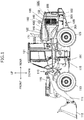
- FIG. 1 is a side view of a wheel loader which is one example of a work machine according to one embodiment of the present invention.
- the wheel loader is made up of a front vehicle body 110 including an arm 111, a bucket 112, front wheels 113, and the like, and a rear vehicle body 120 including an operator's cab 121, a housing 122, rear wheels 123, and the like.
- the arm 111 vertically rotates (moves up and down) by drive of an arm cylinder (not shown), and the bucket 112 vertically rotates (crowds and dumps) by drive of the bucket cylinder 115.
- the front vehicle body 110 and the rear vehicle body 120 are rotatably coupled to each other with a center pin 101, and the front vehicle body 110 horizontally bent with respect to the rear vehicle body 120 by shrinkage of the steering cylinder 116.
- the housing 122 constitutes an outline of a storage chamber accommodating an engine 301, an exhaust gas purifying device 400, a heat exchanger, a variety of hydraulic equipment, and the like. Openings on the right and left side surfaces of the housing 122 are covered by a pair of right and left operable/closable housing covers 130.
- the housing cover 130 is an opening/closing cover of a gull wing type, and configured to be opened substantially horizontally to the ground, with a rotation fulcrum (hinge) provided between the top board of the housing 122 and the housing cover 130.
- the housing covers 130 respectively provided on the right and left side surfaces of the wheel loader 100 have substantially a bilaterally symmetrical shape.
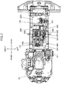
- Figure 2 is a plan view of the wheel loader in a state where the upper structure such as the top board has been removed.
- the storage chamber (storage space) provided inside the housing 122 is divided by a partition 160 into an engine room 122E on the front side of the vehicle and a cooler chamber 122C on the rear side of the vehicle.
- the side surface of the engine room 122E is covered by a part of the housing cover 130, and the upper surface of the engine room 122E is covered by an engine hood 140 constituting the top board of the housing 122.
- the front surface of the engine room 122E is covered by a front plate 811 of a front-side frame 810 (cf. Figure 4 ), and the rear surface of the engine room 122E is covered by the partition 160 of a rear-side frame 161 (cf. Figure 3 ). That is, the engine room 122E is delimited by the part of the pair of right and left housing covers 130, the engine hood 140, the front plate 811 (cf. Figure 4 ), and the partition 160 (cf. Figure 3 ).
- the side surface of the cooler chamber 122C is covered by a part of the housing cover 130, and the upper surface of the cooler chamber 122C is covered by a housing cover 132 for cooler which constitutes the top board of the housing 122.
- the front surface of the cooler chamber 122C is covered by the partition 160, and the rear surface of the cooler chamber 122C is covered by a grille 200. That is, the cooler chamber 122C is delimited by the part of the pair of right and left housing cover 130, the housing cover 132 for cooler, the partition 160, and the grille 200.
- a heat exchanger 501 and a cooling fan unit 502 are disposed inside the cooler chamber 122C.
- the heat exchanger 501 includes: a plurality of heat exchangers such as a radiator 504 (cf. Figure 9 ) that cools the cooling water of the engine 301, an oil cooler that cools a hydraulic oil, and an inter cooler that cools the air pressurized by a supercharger of the engine 301; and a radiator frame for supporting these heat exchangers.
- the cooling fan unit 502 includes a cooling fan 503 (cf. Figure 9 ) for generating cooling wind for cooling the heat exchanger 501 and a shroud for supporting the cooling fan 503 (cf. Figure 9 ).
- heat exchangers such as a transmission oil cooler and a capacitor of an air conditioner for air conditioning in the operator's cab 121, are also fitted in the heat exchanger 501.
- an intake pipe 145 protrudes from the upper surface of the housing cover 132 for cooler, the intake pipe 145 being configured to take air necessary for the drive of the engine 301 via an air cleaner 310 (cf. Figure 3 ).
- the air cleaner 310 is provided immediately behind the partition 160 in the cooler chamber 122C.
- the air cleaner 310 is connected to the engine 301 via the suction pipe.
- Providing the air cleaner 310 in the cooler chamber 122C can reduce an influence of heat from the engine 301 or the exhaust gas purifying device 400 to the air cleaner 310. It is thereby possible to prevent an increase in temperature of air to be sucked by the engine 301 and prevent deterioration in suction efficiency of the engine 301.
- the exhaust gas purifying device 400 for purifying the exhaust gas of the engine 301 is set up above the engine 301 in the engine room 122E.
- a tale pipe 171 for discharging the exhaust gas protrudes from the engine hood 140.
- Figure 3 is a perspective view showing the inside of the cooler chamber 122C
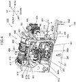
- Figure 4 is a perspective view showing the inside of the engine room 122E.
- the housing cover 130, the engine hood 140, the housing cover 132 for cooler, the grille 200, and the like which constitute the housing 122 are omitted.
- the engine 301 is fitted in a mounting bracket, not shown, in the rear vehicle body 120 in the engine room 122E.
- the supercharger (turbocharger) 302 is fitted in the engine 301.
- the supercharger 302 is set up such that a suction port of a compressor 302a is directed rearward and an exhaust port of a turbine 302b is directed forward.
- the exhaust gas purifying device 400 includes an oxidation catalyst device (DOC:Diesel Oxidation Catalyst) 410, a reducing agent injection device (DRT:Decomposition Reactor Tube) 420, and a selective catalytic reducing device (SCR:Selective Catalytic Reduction) 430, which are installed in an exhaust passage of the engine 301.
- the oxidation catalyst device 410, the reducing agent injection device 420, and the selective catalytic reducing device 430 are disposed in this order from the upstream along the flow of the exhaust gas.
- Each of the after-treatment devices (410, 420, 430) is connected by a connection pipe such as an elbow.
- the oxidation catalyst device 410 includes: an oxidation catalyst for oxidizing and removes nitric monoxide (NO), carbon monoxide (CO), hydrocarbon (HC), and the like contained in the exhaust gas; and a cylindrical DOC casing 411 for holding the oxidation catalyst.
- the reducing agent injection device 420 is installed downstream of the oxidation catalyst device 410.
- the reducing agent injection device 420 includes an injection valve 429 for injection a urea aqueous solution (hereinafter referred to as urea water) being a reducing agent into the exhaust gas to be supplied to the selective catalytic reducing device 430, and a cylindrical DRT housing 421 for holding the injection valve 429.
- the injection valve 429 is provided substantially at the center of the DRT housing 421.
- the injection valve 429 injects urea water into the DRT housing 421 in accordance with a control signal from a control device, not shown.
- the injection valve 429 is opened or closed by allowing a current to flow in a coil to generate a magnetic field in a magnetic circuit including a mover and a core and cause action of magnetic suction force that attracts the mover to the core, and the injection valve 429 has a similar configuration to that of a known electromagnetic driving fuel injection valve (injector).
- the selective catalytic reducing device 430 is installed downstream of the reducing agent injection device 420.
- the selective catalytic reducing device 430 includes a reduction catalyst for performing reduction purification treatment on a nitrogen oxide (NOx) contained in the exhaust gas by using urea water as the reducing agent, and a cylindrical SCR housing 431 for holding the reduction catalyst.
- the oxidation catalyst is provided downstream of the reduction catalyst.
- the injection valve 429 is connected to a urea water tank 127 via pipes (a suction pipe 425a and a reducing agent supply pipe 425s).
- the urea water tank 127 is a container for storing the urea water as the reducing agent.
- a urea water pump 128 is provided between the injection valve 429 in the engine room 122E and the urea water tank 127 in the cooler chamber 122C.
- the urea water pump 128 is fixed to the partition 160 inside the cooler chamber 122C.
- the urea water pump 128 is an electric pump for sucking the urea water in the urea water tank 127 to convey the urea water to the injection valve 429.
- the injection valve 429 shown in Figure 4 injects into the exhaust passage the urea water supplied from the urea water tank 127 by the urea water pump 128.
- ammonia is generated from the urea water by using the reduction catalyst of the selective catalytic reducing device 430, and ammonia causes a reduction reaction of NOx in the exhaust gas, to be decomposed into water and nitrogen.
- Ammonia in the exhaust gas is reduced by the oxidation catalyst provided downstream of the reduction catalyst in the selective catalytic reducing device 430.
- a rear frame 220 constituting the rear vehicle body 120 is formed in the shape of a rectangular frame, made up of a pair of right and left longitudinal plates 221 and a lateral plate 222 having the front end and the rear end respectively coupled to the pair of right and left longitudinal plates 221 (the lateral plate at the front end is not shown).
- the exhaust gas purifying device 400 is supported by the front-side frame 810 and the rear-side frame 161 via a base bracket 820 being a support structure.
- the rear-side frame 161 is fixed to the longitudinal plate 221 via a bracket 221b that is welded inside each of the pair of right and left longitudinal plates 221 constituting the rear frame 220.
- the rear-side frame 161 is a gate-shaped support member, and a pair of right and left leg portions 162 is respectively fitted on the pair of right and left longitudinal plates 221.
- a horizontally and vertically extending support beam 163 is firmly fixed to the pair of right and left leg portions 162.
- a protruding reception portion 163a protruding forward is provided in the support beam 163.
- the tabular partition 160 described above is fitted on the rear surface of the rear-side frame 161 by using a fastening member such as a bolt or a nut.
- the front-side frame 810 has a similar configuration to that of the rear-side frame 161.
- the front-side frame 810 is fixed to the pair of right and left longitudinal plates 221 constituting the rear frame 220.
- the front-side frame 810 is a gate-shaped support member, and a pair of right and left leg portions 812 is respectively fitted on the pair of right and left longitudinal plates 221.
- a horizontally and vertically extending support beam 813 is firmly fixed to the pair of right and left leg portions 812.
- a protruding reception portion 813a protruding rearward is provided in the support beam 813.
- the tabular front plate 811 is fitted on the front surface of the front-side frame 810 by using fastening members such as a bolt and a nut.
- a front leg 838 of the base bracket 820 is mounted in the protruding reception portion 813a of the front-side frame 810, and a rear leg 839 of the base bracket 820 is mounted in the protruding reception portion 163a of the rear-side frame 161.
- the base bracket 820 is fixed to and supported by the front-side frame 810 and the rear-side frame 161.
- the exhaust gas purifying device 400 is disposed and fixed in a predetermined position above the engine 301.
- Figure 5 is a view of the engine room 122E seen from the left side.
- the housing cover 130 is omitted.
- the engine hood 140 covering the engine room 122E is provided above the engine 301 and the exhaust gas purifying device 400.
- the front end of the engine hood 140 is fitted on the upper end of the front-side frame 810, and the rear end of the engine hood 140 is fitted on the upper end of the rear-side frame 161. That is, the front-side frame 810 and the rear-side frame 161 are support structures for supporting the engine hood 140 covering the engine room 122E thereabove.
- Figure 6 is a perspective view of the housing 122 seen from left obliquely above.
- an exhaust duct 149 is provided in a tabular ceiling board 141 of the engine hood 140.
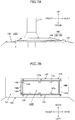
- Figure 7A is a side schematic view of the exhaust duct 149
- Figure 7B is a plan schematic view of the exhaust duct 149.
- an opening cover 142 is omitted.
- Figure 8 is a side schematic view of the exhaust duct 149 in a disassembled state.
- the exhaust duct 149 is an exhaust passage forming element for forming an exhaust passage that discharges the air inside the engine room 122E to the outside of the engine room 122E, and protrudes upward from the ceiling board 141.
- the exhaust duct 149 has a cover support frame 146 fitted on an opening 144 in the ceiling board 141 and has the opening cover 142.
- the opening cover 142 is obtained by processing a tabular member to be formed into a bottom-open quadrangular prismatic trapezoidal shape.
- a rectangular opening 144 is provided in the ceiling board 141 constituting the engine hood 140, the opening 144 having a pair of longer sides along the longitudinal direction and a pair of shorter sides along the horizontal direction.
- the opening 144 is provided immediately above the reducing agent injection device 420.
- the cover support frame 146 in the shape of a rectangular frame, a size larger than the opening 144, is provided around the opening 144.
- the cover support frame 146 is the support structure for supporting the opening cover 142, and includes a pair of right and left longitudinal frames 147 extending longitudinally and a pair of front and rear lateral frames 148 extending horizontally.
- the longitudinal frame 147 and the lateral frame 148 are formed by an angle (angle steel) having an L-shape in cross section, a bent steel member, or the like.
- the longitudinal frame 147 and the lateral frame 148 have base portions 147b, 148b fixed to the periphery of the opening 144, and a plurality of support portions 147s, 148s rising from base portions 147b, 148b. Fitting pieces 147a, 148a are provided at the tips of the plurality of support portions 147s, 148s.
- the opening cover 142 is fixed to the fitting pieces 147a, 148a of the support portions 147s, 148s by the bolt and the nut.
- the opening cover 142 has a larger area than that of the opening 144 and covers the entire opening 144 from above. As shown in Figure 7A , a clearance D is formed between the lower end of the outer periphery of the opening cover 142 and the upper surface of the ceiling board 141.
- the air in the engine room 122E is warmed by the heating elements such as the engine 301 and the exhaust gas purifying device 400 and rises, to be introduced into the exhaust duct 149.
- the air introduced into the exhaust duct 149 passes upward through the inside of the rectangular cover support frame 146 and flows longitudinally and horizontally along the opening cover 142.
- the air passes through the clearance between the support portions in the cover support frame 146 and discharged to the outside from the clearance D between the cover support frame 146 and the ceiling board 141.
- FIG. 9 is a view for describing the urea water supply system and the cooling water circulation system of the exhaust gas purifying device 400.
- the urea water supply system is made up of the urea water pump 128, the urea water tank 127, and pipes.
- the urea water pump 128 and the urea water tank 127 are connected by the suction pipe 425a and a return pipe 425b.
- the urea water pump 128 and the injection valve 429 are connected by the reducing agent supply pipe 425s.
- a urea water suction port 426a is disposed in the vicinity of the bottom of the urea water tank 127 in the suction pipe 425a, and a urea water discharge port 426b is disposed in the vicinity of the top of the urea water tank 127 in the return pipe 425b.
- Urea water sucked from the bottom of the urea water tank 127 by the urea water pump 128 is supplied into the reducing agent supply pipe 425s and pressurized.
- the urea water in the reducing agent supply pipe 425s is injected and supplied to the exhaust passage of the engine 301 by opening of the injection valve 429. An excess of the urea water is returned to the urea water tank 127 via the return pipe 425b.
- the exhaust gas purifying device 400 includes the cooling water circulation system in order to prevent deterioration in quality of urea water due to an increase in temperature of the urea water.
- the cooling water circulation system is a system made up of a cooling water pump, not shown, a pipe, and valves, and guiding cooling water (engine cooling water) to the urea water tank 127 and the injection valve 429 to cause the cooling water and the urea water exchange heat.
- the cooling water circulation system includes an engine cooling system 880, and a refrigerant pipe 881 for guiding the cooling water from the engine cooling system 880 to the urea water tank 127 and the injection valve 429.
- the engine cooling system 880 cools the engine 301 by supplying the engine 301 with the cooling water cooled by the radiator 504.
- the engine 301 is provided with a thermostat 305 and a cooling water pump (not shown) for circulating the engine cooling water.
- the thermostat 305 opens or closes a route of the engine cooling system 880 between a fully closed state and a fully opened state in accordance with the temperature of the engine cooling water.
- a bypass route that bypasses the engine cooling water so as not to supply the engine cooling water to the radiator 504 is provided when the thermostat 305 fully closes the route.
- the engine cooling water circulates in the engine and is warmed due to heat generation of the engine 301.
- the refrigerant pipe 881 through which the cooling water flows has a first refrigerant pipe 435 that is set up so as to pass through the injection valve 429 and a second refrigerant pipe 437 that is set up so as to pass of the urea water tank 127.
- the first refrigerant pipe 435 has a first supply pipe 435s for guiding the cooling water to the injection valve 429 and a first return pipe 435r for returning the engine cooling water from the injection valve 429 to the engine 301.
- the second refrigerant pipe 437 has a second supply pipe 437s for guiding the cooling water to the urea water tank 127 and a second return pipe 437r for returning the cooling water from the urea water tank 127 to the engine 301.
- the second refrigerant pipe 437 is provided with a switching valve 437v that is switched between the fully closed state and the fully opened state in accordance with a control signal from the control device, not shown.
- each of the suction pipe 425a and the return pipe 425b is inserted from the upper surface of the urea water tank 127 into the urea water tank 127.
- the suction pipe 425a and the return pipe 425b are connected by the urea water pump 128 fitted on the partition 160.
- the reducing agent supply pipe 425s, through which the urea water discharged from the urea water pump 128 flows, is guided to the engine room 122E via the opening in the partition 160 and connected to the injection valve 429 (cf. Figure 5 ).
- the second supply pipe 437s constituting the second refrigerant pipe 437 is guided from the engine room 122E to the cooler chamber 122C via the opening in the partition 160, to be inserted from the upper surface of the urea water tank 127 into the urea water tank 127.
- the second return pipe 437r constituting the second refrigerant pipe 437 is guided from the upper surface of the urea water tank 127 to the outside of the urea water tank 127 and further guide to the engine room 122E via the opening in the partition 160, to be connected to the engine 301. That is, the second refrigerant pipe 437 through which the engine cooling water flows is set up so as to pass through the urea water tank 127.
- the refrigerant pipe 881 is guided from the engine 301 to the partition 160 along the base bracket 820 and branched into the first refrigerant pipe 435 and the second refrigerant pipe 437.
- the second refrigerant pipe 437 is guided to the cooler chamber 122C via the opening in the partition 160.
- the first supply pipe 435s constituting the first refrigerant pipe 435 is guided upward along the partition 160 and further guided front obliquely upward to the rear portion of the exhaust duct 149.
- the first supply pipe 435s is bent in the exhaust duct 149 and guided front obliquely downward to the front portion of the exhaust duct 149.
- the first supply pipe 435s is turned back below the front portion of the exhaust duct 149 and guided rear obliquely downward to the injection valve 429, to be connected to the injection valve 429.
- the first return pipe 435r constituting the first refrigerant pipe 435 is guided front obliquely upward from the injection valve 429 and turned back in the vicinity of the injection valve 429, and is then guided rear obliquely downward along the DRT housing 421.
- the first return pipe 435r is bent downward in the vicinity of the partition 160 and connected to the engine 301.
- the reducing agent supply pipe 425s is guided from the opening in the partition 160 to the engine room 122E and routed in the state of being brought close to or into contact with the first supply pipe 435s by a similar route to that of the first supply pipe 435s.
- the temperature of the urea water can be held appropriate through the heat exchange between the urea water and the cooling water in the reducing agent supply pipe 425s.
- the reducing agent supply pipe 425s is guided front obliquely upward to the rear portion of the exhaust duct 149 along with the first supply pipe 435s.
- the reducing agent supply pipe 425s is bent in the exhaust duct 149 and guided front obliquely downward to the front portion of the exhaust duct 149.
- the reducing agent supply pipe 425s is turned back below the front portion of the exhaust duct 149 and guided rear obliquely downward to the injection valve 429, to be connected to the injection valve 429.
- the cooling water pump (not shown) for circulating the cooling water is driven by the engine 301. Therefore, when the engine 301 stops, the cooling water pump also stops and the circulation of the cooling water thus stops. However, radiation heat is radiated from the engine 301 even after the engine has stopped, and hence the injection valve 429 needs to be cooled even after the engine has stopped.
- the present embodiment is configured such that the first supply pipe 435s connected to the injection valve 429 is provided above the injection valve 429 and the cooling water remains (is reserved) in the pipe even after stopping of the engine.
- Figure 10 is a view for describing a reservoir area RA of the first supply pipe 435s and the reducing agent supply pipe 425s.
- each of regions from a top portion TP of the center of the tubes (first supply pipe 435s and reducing agent supply pipe 425s) to connection portions (CP1, CP2) between the pipes (first supply pipe 435s and reducing agent supply pipe 425s) and the injection valve 429 is defined as a reservoir area RA.
- the reservoir area RA is disposed between the reducing agent injection device 420 and the exhaust duct 149.
- a vertical dimension (height dimension) H1 of the reservoir area RA of the first supply pipe 435s is set to about 150 mm to 200 mm.
- a vertical dimension (height dimension) H2 of the reservoir area RA of the reducing agent supply pipe 425s is set to about 150 mm to 200 mm.
- the top portion TP of the first supply pipe 435s and the reducing agent supply pipe 425s is located inside the exhaust duct 149 and above the upper surface of the ceiling board 141.
- a longitudinal length L1 of the reservoir area RA is smaller than a longitudinal length L2 of the opening 144.
- the first supply pipe 435s and the reducing agent supply pipe 425s are routed such that the entire reservoir areas RA of the first supply pipe 435s and the reducing agent supply pipe 425s are held inside the opening 144 in plan view.
- Each pipe is made of a hose having flexibility, a bracket and a metal fitting for routing each pipe are provided in each of the constituent members such as the engine hood 140, the rear-side frame 161, and the partition 160, and each pipe is supported in a predetermined position by using the bracket and the metal fitting for routing.
- the air warmed inside the engine room 122E rises to be discharged to the outside of the engine room 122E via the exhaust duct 149.
- the top portion TP and the reservoir areas RA of the first supply pipe 435s and the reducing agent supply pipe 425s on a route (on a flow passage) for a flow F (cf. schematic arrows shown in Figure 5 ) generated by natural convection, it is possible to effectively cool the cooling water and the urea water that are reserved in the reservoir areas RA after stopping of the engine.
- a reservoir portion 900 may be disposed in the hose so that the first supply pipe 435s may include the hose and the reservoir portion 900.
- the reservoir portion 900 has a larger cross sectional area of the flow passage than the cross sectional area of the flow passage of the hose, and is provided for the purpose of expanding the volume of the cooling water. Disposing the reservoir portion 900 in the exhaust duct 149 enables effective cooling of the cooling water in the reservoir portion 900.
- the cooling water circulation system is provided so as to prevent an increase in temperature of the urea water, but the cooling water circulation system may be used for thawing frozen urea water.
- the cooling water circulation system may be used for thawing frozen urea water.
- the reducing agent injection device 420 cannot supply the urea water.
- the use of the reducing agent injection device 420 requires thawing of the frozen urea water and further requires prevention of the urea water from being frozen again.
- the cooling water warmed by heat exchange with the engine 301 is guided to the injection valve 429 and the urea water tank 127, to enable thawing of the frozen urea water and prevention of the urea water from being frozen again.
- the present invention is not limited thereto.
- the present invention is applicable to a work machine provided with the exhaust gas purifying device 400 using a variety of reducing agents such as an ammonia aqueous solution.
- the present invention is not limited thereto and applicable to a variety of work machines such as a hydraulic shovel or a crane.
Landscapes
- Engineering & Computer Science (AREA)
- Chemical & Material Sciences (AREA)
- Combustion & Propulsion (AREA)
- General Engineering & Computer Science (AREA)
- Mechanical Engineering (AREA)
- Chemical Kinetics & Catalysis (AREA)
- Mining & Mineral Resources (AREA)
- Civil Engineering (AREA)
- Structural Engineering (AREA)
- Health & Medical Sciences (AREA)
- Transportation (AREA)
- General Chemical & Material Sciences (AREA)
- Analytical Chemistry (AREA)
- Environmental & Geological Engineering (AREA)
- Oil, Petroleum & Natural Gas (AREA)
- Biomedical Technology (AREA)
- Toxicology (AREA)
- Exhaust Gas After Treatment (AREA)
- Exhaust Gas Treatment By Means Of Catalyst (AREA)
- Component Parts Of Construction Machinery (AREA)
- Cooling, Air Intake And Gas Exhaust, And Fuel Tank Arrangements In Propulsion Units (AREA)
Applications Claiming Priority (2)
| Application Number | Priority Date | Filing Date | Title |
|---|---|---|---|
| JP2016066541A JP6548224B2 (ja) | 2016-03-29 | 2016-03-29 | 作業機械 |
| PCT/JP2017/000181 WO2017168915A1 (ja) | 2016-03-29 | 2017-01-05 | 作業機械 |
Publications (3)
| Publication Number | Publication Date |
|---|---|
| EP3438425A1 EP3438425A1 (en) | 2019-02-06 |
| EP3438425A4 EP3438425A4 (en) | 2019-11-06 |
| EP3438425B1 true EP3438425B1 (en) | 2020-11-11 |
Family
ID=59963974
Family Applications (1)
| Application Number | Title | Priority Date | Filing Date |
|---|---|---|---|
| EP17773465.4A Active EP3438425B1 (en) | 2016-03-29 | 2017-01-05 | Working machine |
Country Status (6)
| Country | Link |
|---|---|
| US (1) | US10422264B2 (enExample) |
| EP (1) | EP3438425B1 (enExample) |
| JP (1) | JP6548224B2 (enExample) |
| KR (1) | KR102002513B1 (enExample) |
| CN (1) | CN107923285B (enExample) |
| WO (1) | WO2017168915A1 (enExample) |
Families Citing this family (11)
| Publication number | Priority date | Publication date | Assignee | Title |
|---|---|---|---|---|
| DE102018102845A1 (de) * | 2018-02-08 | 2019-08-08 | Man Truck & Bus Ag | Schalldämpfer mit integrierter Trittstufe |
| JP7089981B2 (ja) * | 2018-08-10 | 2022-06-23 | 北越工業株式会社 | エンジン駆動型作業機 |
| DE102018213895A1 (de) * | 2018-08-17 | 2020-02-20 | Robert Bosch Gmbh | Anordnung zur Nachbehandlung des Abgases einer Brennkraftmaschine und Verfahren zum Betreiben einer solchen |
| JP7100605B2 (ja) * | 2019-04-25 | 2022-07-13 | 株式会社クボタ | 整流板の取付構造及び作業車 |
| US11800692B2 (en) | 2020-03-19 | 2023-10-24 | Nooter/Eriksen, Inc. | System and method for data center cooling with carbon dioxide |
| CN112282917A (zh) * | 2020-09-25 | 2021-01-29 | 潍柴动力股份有限公司 | 发动机热管理系统及车辆 |
| US12140065B2 (en) | 2020-09-28 | 2024-11-12 | Nooter/Eriksen, Inc. | System and method for treating gas turbine exhaust gas |
| US12031468B2 (en) | 2020-09-28 | 2024-07-09 | Nooter/Eriksen, Inc. | System and method for treating gas turbine exhaust gas |
| US11668219B2 (en) | 2020-09-28 | 2023-06-06 | Nooter/Eriksen, Inc. | System and method for treating process exhaust gas |
| US12077938B2 (en) * | 2021-10-12 | 2024-09-03 | Caterpillar Inc. | Secondary control system and method for mounting with service orientation |
| CN117738272A (zh) * | 2024-01-29 | 2024-03-22 | 徐工集团工程机械股份有限公司科技分公司 | 一种机舱冷却除尘系统及装载机 |
Family Cites Families (11)
| Publication number | Priority date | Publication date | Assignee | Title |
|---|---|---|---|---|
| JPS563517A (en) | 1979-06-22 | 1981-01-14 | Furukawa Electric Co Ltd | Method of connecting wavy aluminum sheath power cable |
| JP5369919B2 (ja) * | 2009-06-12 | 2013-12-18 | コベルコ建機株式会社 | 作業機械 |
| JP2013241809A (ja) * | 2012-05-22 | 2013-12-05 | Caterpillar Sarl | 機体および作業機械 |
| JP5591303B2 (ja) * | 2012-10-25 | 2014-09-17 | 株式会社小松製作所 | エンジン室の換気構造 |
| JP5799001B2 (ja) * | 2012-10-25 | 2015-10-21 | 株式会社小松製作所 | 尿素水溶液配管の冷却構造 |
| DE112013000161C5 (de) * | 2013-03-15 | 2023-03-16 | Komatsu Ltd. | Abgasnachbehandlungseinheit und ein diese enthaltendes Baufahrzeug |
| WO2014155510A1 (ja) * | 2013-03-26 | 2014-10-02 | 株式会社小松製作所 | ホイールローダ |
| IN2013DE01690A (enExample) * | 2013-06-05 | 2015-07-10 | Caterpillar Global Mining Expanded Products Pty Ltd | |
| JP2015197079A (ja) * | 2014-04-02 | 2015-11-09 | ニッタ株式会社 | 昇温及び遮熱配管 |
| JP5603517B2 (ja) * | 2014-05-13 | 2014-10-08 | 株式会社小松製作所 | 排気ガス後処理ユニット、及びこれを搭載する建設車両 |
| JP6258791B2 (ja) * | 2014-06-06 | 2018-01-10 | 日立建機株式会社 | 建設機械 |
-
2016
- 2016-03-29 JP JP2016066541A patent/JP6548224B2/ja active Active
-
2017
- 2017-01-05 CN CN201780002873.8A patent/CN107923285B/zh active Active
- 2017-01-05 EP EP17773465.4A patent/EP3438425B1/en active Active
- 2017-01-05 US US15/754,299 patent/US10422264B2/en active Active
- 2017-01-05 KR KR1020187005279A patent/KR102002513B1/ko active Active
- 2017-01-05 WO PCT/JP2017/000181 patent/WO2017168915A1/ja not_active Ceased
Non-Patent Citations (1)
| Title |
|---|
| None * |
Also Published As
| Publication number | Publication date |
|---|---|
| US20180238220A1 (en) | 2018-08-23 |
| JP2017180214A (ja) | 2017-10-05 |
| US10422264B2 (en) | 2019-09-24 |
| CN107923285B (zh) | 2020-01-21 |
| KR102002513B1 (ko) | 2019-07-22 |
| EP3438425A1 (en) | 2019-02-06 |
| CN107923285A (zh) | 2018-04-17 |
| KR20180031754A (ko) | 2018-03-28 |
| JP6548224B2 (ja) | 2019-07-24 |
| WO2017168915A1 (ja) | 2017-10-05 |
| EP3438425A4 (en) | 2019-11-06 |
Similar Documents
| Publication | Publication Date | Title |
|---|---|---|
| US10422264B2 (en) | Work machine | |
| US8973353B2 (en) | Exhaust gas post-treatment unit and construction vehicle carrying same | |
| JP5439634B1 (ja) | 排気ガス後処理装置を搭載した建設車両 | |
| EP3431669B1 (en) | Construction machine | |
| JP5799001B2 (ja) | 尿素水溶液配管の冷却構造 | |
| KR102022490B1 (ko) | 건설 기계 | |
| US9194104B2 (en) | Wheel loader | |
| US20140290224A1 (en) | Wheel loader | |
| JP5723493B1 (ja) | 油圧ショベル | |
| JP5603517B2 (ja) | 排気ガス後処理ユニット、及びこれを搭載する建設車両 | |
| KR101801511B1 (ko) | 작업 차량 | |
| JP2017179797A (ja) | 作業機械 | |
| US10215071B2 (en) | Exhaust gas aftertreatment unit and work vehicle | |
| JP5481604B1 (ja) | 排気処理ユニット及び排気処理ユニットを搭載する作業車両 | |
| JP2014101865A (ja) | 建設機械 |
Legal Events
| Date | Code | Title | Description |
|---|---|---|---|
| STAA | Information on the status of an ep patent application or granted ep patent |
Free format text: STATUS: THE INTERNATIONAL PUBLICATION HAS BEEN MADE |
|
| PUAI | Public reference made under article 153(3) epc to a published international application that has entered the european phase |
Free format text: ORIGINAL CODE: 0009012 |
|
| STAA | Information on the status of an ep patent application or granted ep patent |
Free format text: STATUS: REQUEST FOR EXAMINATION WAS MADE |
|
| 17P | Request for examination filed |
Effective date: 20180323 |
|
| AK | Designated contracting states |
Kind code of ref document: A1 Designated state(s): AL AT BE BG CH CY CZ DE DK EE ES FI FR GB GR HR HU IE IS IT LI LT LU LV MC MK MT NL NO PL PT RO RS SE SI SK SM TR |
|
| AX | Request for extension of the european patent |
Extension state: BA ME |
|
| DAV | Request for validation of the european patent (deleted) | ||
| DAX | Request for extension of the european patent (deleted) | ||
| RAP1 | Party data changed (applicant data changed or rights of an application transferred) |
Owner name: HITACHI CONSTRUCTION MACHINERY CO., LTD. |
|
| A4 | Supplementary search report drawn up and despatched |
Effective date: 20191009 |
|
| RIC1 | Information provided on ipc code assigned before grant |
Ipc: B60K 11/02 20060101ALI20191003BHEP Ipc: F01N 3/08 20060101AFI20191003BHEP Ipc: F01N 3/20 20060101ALI20191003BHEP Ipc: E02F 9/08 20060101ALI20191003BHEP Ipc: F01P 3/20 20060101ALI20191003BHEP Ipc: E02F 9/00 20060101ALI20191003BHEP Ipc: F01N 13/08 20100101ALI20191003BHEP Ipc: B01D 53/94 20060101ALI20191003BHEP Ipc: B60K 13/04 20060101ALI20191003BHEP Ipc: F01P 7/16 20060101ALI20191003BHEP Ipc: B60K 11/06 20060101ALI20191003BHEP Ipc: F01N 3/24 20060101ALI20191003BHEP |
|
| GRAP | Despatch of communication of intention to grant a patent |
Free format text: ORIGINAL CODE: EPIDOSNIGR1 |
|
| STAA | Information on the status of an ep patent application or granted ep patent |
Free format text: STATUS: GRANT OF PATENT IS INTENDED |
|
| INTG | Intention to grant announced |
Effective date: 20200717 |
|
| GRAS | Grant fee paid |
Free format text: ORIGINAL CODE: EPIDOSNIGR3 |
|
| GRAA | (expected) grant |
Free format text: ORIGINAL CODE: 0009210 |
|
| STAA | Information on the status of an ep patent application or granted ep patent |
Free format text: STATUS: THE PATENT HAS BEEN GRANTED |
|
| AK | Designated contracting states |
Kind code of ref document: B1 Designated state(s): AL AT BE BG CH CY CZ DE DK EE ES FI FR GB GR HR HU IE IS IT LI LT LU LV MC MK MT NL NO PL PT RO RS SE SI SK SM TR |
|
| REG | Reference to a national code |
Ref country code: GB Ref legal event code: FG4D |
|
| REG | Reference to a national code |
Ref country code: CH Ref legal event code: EP |
|
| REG | Reference to a national code |
Ref country code: AT Ref legal event code: REF Ref document number: 1333685 Country of ref document: AT Kind code of ref document: T Effective date: 20201115 |
|
| REG | Reference to a national code |
Ref country code: DE Ref legal event code: R096 Ref document number: 602017027444 Country of ref document: DE |
|
| REG | Reference to a national code |
Ref country code: IE Ref legal event code: FG4D |
|
| REG | Reference to a national code |
Ref country code: SE Ref legal event code: TRGR |
|
| REG | Reference to a national code |
Ref country code: NL Ref legal event code: MP Effective date: 20201111 |
|
| REG | Reference to a national code |
Ref country code: AT Ref legal event code: MK05 Ref document number: 1333685 Country of ref document: AT Kind code of ref document: T Effective date: 20201111 |
|
| PG25 | Lapsed in a contracting state [announced via postgrant information from national office to epo] |
Ref country code: PT Free format text: LAPSE BECAUSE OF FAILURE TO SUBMIT A TRANSLATION OF THE DESCRIPTION OR TO PAY THE FEE WITHIN THE PRESCRIBED TIME-LIMIT Effective date: 20210311 Ref country code: RS Free format text: LAPSE BECAUSE OF FAILURE TO SUBMIT A TRANSLATION OF THE DESCRIPTION OR TO PAY THE FEE WITHIN THE PRESCRIBED TIME-LIMIT Effective date: 20201111 Ref country code: FI Free format text: LAPSE BECAUSE OF FAILURE TO SUBMIT A TRANSLATION OF THE DESCRIPTION OR TO PAY THE FEE WITHIN THE PRESCRIBED TIME-LIMIT Effective date: 20201111 Ref country code: NO Free format text: LAPSE BECAUSE OF FAILURE TO SUBMIT A TRANSLATION OF THE DESCRIPTION OR TO PAY THE FEE WITHIN THE PRESCRIBED TIME-LIMIT Effective date: 20210211 Ref country code: GR Free format text: LAPSE BECAUSE OF FAILURE TO SUBMIT A TRANSLATION OF THE DESCRIPTION OR TO PAY THE FEE WITHIN THE PRESCRIBED TIME-LIMIT Effective date: 20210212 |
|
| PG25 | Lapsed in a contracting state [announced via postgrant information from national office to epo] |
Ref country code: AT Free format text: LAPSE BECAUSE OF FAILURE TO SUBMIT A TRANSLATION OF THE DESCRIPTION OR TO PAY THE FEE WITHIN THE PRESCRIBED TIME-LIMIT Effective date: 20201111 Ref country code: BG Free format text: LAPSE BECAUSE OF FAILURE TO SUBMIT A TRANSLATION OF THE DESCRIPTION OR TO PAY THE FEE WITHIN THE PRESCRIBED TIME-LIMIT Effective date: 20210211 Ref country code: PL Free format text: LAPSE BECAUSE OF FAILURE TO SUBMIT A TRANSLATION OF THE DESCRIPTION OR TO PAY THE FEE WITHIN THE PRESCRIBED TIME-LIMIT Effective date: 20201111 Ref country code: LV Free format text: LAPSE BECAUSE OF FAILURE TO SUBMIT A TRANSLATION OF THE DESCRIPTION OR TO PAY THE FEE WITHIN THE PRESCRIBED TIME-LIMIT Effective date: 20201111 Ref country code: IS Free format text: LAPSE BECAUSE OF FAILURE TO SUBMIT A TRANSLATION OF THE DESCRIPTION OR TO PAY THE FEE WITHIN THE PRESCRIBED TIME-LIMIT Effective date: 20210311 |
|
| REG | Reference to a national code |
Ref country code: LT Ref legal event code: MG9D |
|
| PG25 | Lapsed in a contracting state [announced via postgrant information from national office to epo] |
Ref country code: HR Free format text: LAPSE BECAUSE OF FAILURE TO SUBMIT A TRANSLATION OF THE DESCRIPTION OR TO PAY THE FEE WITHIN THE PRESCRIBED TIME-LIMIT Effective date: 20201111 |
|
| PG25 | Lapsed in a contracting state [announced via postgrant information from national office to epo] |
Ref country code: SM Free format text: LAPSE BECAUSE OF FAILURE TO SUBMIT A TRANSLATION OF THE DESCRIPTION OR TO PAY THE FEE WITHIN THE PRESCRIBED TIME-LIMIT Effective date: 20201111 Ref country code: CZ Free format text: LAPSE BECAUSE OF FAILURE TO SUBMIT A TRANSLATION OF THE DESCRIPTION OR TO PAY THE FEE WITHIN THE PRESCRIBED TIME-LIMIT Effective date: 20201111 Ref country code: EE Free format text: LAPSE BECAUSE OF FAILURE TO SUBMIT A TRANSLATION OF THE DESCRIPTION OR TO PAY THE FEE WITHIN THE PRESCRIBED TIME-LIMIT Effective date: 20201111 Ref country code: LT Free format text: LAPSE BECAUSE OF FAILURE TO SUBMIT A TRANSLATION OF THE DESCRIPTION OR TO PAY THE FEE WITHIN THE PRESCRIBED TIME-LIMIT Effective date: 20201111 Ref country code: SK Free format text: LAPSE BECAUSE OF FAILURE TO SUBMIT A TRANSLATION OF THE DESCRIPTION OR TO PAY THE FEE WITHIN THE PRESCRIBED TIME-LIMIT Effective date: 20201111 Ref country code: RO Free format text: LAPSE BECAUSE OF FAILURE TO SUBMIT A TRANSLATION OF THE DESCRIPTION OR TO PAY THE FEE WITHIN THE PRESCRIBED TIME-LIMIT Effective date: 20201111 |
|
| REG | Reference to a national code |
Ref country code: DE Ref legal event code: R097 Ref document number: 602017027444 Country of ref document: DE |
|
| PG25 | Lapsed in a contracting state [announced via postgrant information from national office to epo] |
Ref country code: MC Free format text: LAPSE BECAUSE OF FAILURE TO SUBMIT A TRANSLATION OF THE DESCRIPTION OR TO PAY THE FEE WITHIN THE PRESCRIBED TIME-LIMIT Effective date: 20201111 Ref country code: DK Free format text: LAPSE BECAUSE OF FAILURE TO SUBMIT A TRANSLATION OF THE DESCRIPTION OR TO PAY THE FEE WITHIN THE PRESCRIBED TIME-LIMIT Effective date: 20201111 |
|
| REG | Reference to a national code |
Ref country code: CH Ref legal event code: PL |
|
| PLBE | No opposition filed within time limit |
Free format text: ORIGINAL CODE: 0009261 |
|
| STAA | Information on the status of an ep patent application or granted ep patent |
Free format text: STATUS: NO OPPOSITION FILED WITHIN TIME LIMIT |
|
| PG25 | Lapsed in a contracting state [announced via postgrant information from national office to epo] |
Ref country code: LU Free format text: LAPSE BECAUSE OF NON-PAYMENT OF DUE FEES Effective date: 20210105 |
|
| REG | Reference to a national code |
Ref country code: BE Ref legal event code: MM Effective date: 20210131 |
|
| 26N | No opposition filed |
Effective date: 20210812 |
|
| GBPC | Gb: european patent ceased through non-payment of renewal fee |
Effective date: 20210211 |
|
| PG25 | Lapsed in a contracting state [announced via postgrant information from national office to epo] |
Ref country code: FR Free format text: LAPSE BECAUSE OF NON-PAYMENT OF DUE FEES Effective date: 20210111 Ref country code: AL Free format text: LAPSE BECAUSE OF FAILURE TO SUBMIT A TRANSLATION OF THE DESCRIPTION OR TO PAY THE FEE WITHIN THE PRESCRIBED TIME-LIMIT Effective date: 20201111 Ref country code: NL Free format text: LAPSE BECAUSE OF FAILURE TO SUBMIT A TRANSLATION OF THE DESCRIPTION OR TO PAY THE FEE WITHIN THE PRESCRIBED TIME-LIMIT Effective date: 20201111 Ref country code: IT Free format text: LAPSE BECAUSE OF FAILURE TO SUBMIT A TRANSLATION OF THE DESCRIPTION OR TO PAY THE FEE WITHIN THE PRESCRIBED TIME-LIMIT Effective date: 20201111 |
|
| PG25 | Lapsed in a contracting state [announced via postgrant information from national office to epo] |
Ref country code: LI Free format text: LAPSE BECAUSE OF NON-PAYMENT OF DUE FEES Effective date: 20210131 Ref country code: SI Free format text: LAPSE BECAUSE OF FAILURE TO SUBMIT A TRANSLATION OF THE DESCRIPTION OR TO PAY THE FEE WITHIN THE PRESCRIBED TIME-LIMIT Effective date: 20201111 Ref country code: CH Free format text: LAPSE BECAUSE OF NON-PAYMENT OF DUE FEES Effective date: 20210131 |
|
| PG25 | Lapsed in a contracting state [announced via postgrant information from national office to epo] |
Ref country code: ES Free format text: LAPSE BECAUSE OF FAILURE TO SUBMIT A TRANSLATION OF THE DESCRIPTION OR TO PAY THE FEE WITHIN THE PRESCRIBED TIME-LIMIT Effective date: 20201111 Ref country code: IE Free format text: LAPSE BECAUSE OF NON-PAYMENT OF DUE FEES Effective date: 20210105 Ref country code: GB Free format text: LAPSE BECAUSE OF NON-PAYMENT OF DUE FEES Effective date: 20210211 |
|
| PG25 | Lapsed in a contracting state [announced via postgrant information from national office to epo] |
Ref country code: IS Free format text: LAPSE BECAUSE OF FAILURE TO SUBMIT A TRANSLATION OF THE DESCRIPTION OR TO PAY THE FEE WITHIN THE PRESCRIBED TIME-LIMIT Effective date: 20210311 |
|
| PG25 | Lapsed in a contracting state [announced via postgrant information from national office to epo] |
Ref country code: BE Free format text: LAPSE BECAUSE OF NON-PAYMENT OF DUE FEES Effective date: 20210131 |
|
| PG25 | Lapsed in a contracting state [announced via postgrant information from national office to epo] |
Ref country code: CY Free format text: LAPSE BECAUSE OF FAILURE TO SUBMIT A TRANSLATION OF THE DESCRIPTION OR TO PAY THE FEE WITHIN THE PRESCRIBED TIME-LIMIT Effective date: 20201111 |
|
| PG25 | Lapsed in a contracting state [announced via postgrant information from national office to epo] |
Ref country code: HU Free format text: LAPSE BECAUSE OF FAILURE TO SUBMIT A TRANSLATION OF THE DESCRIPTION OR TO PAY THE FEE WITHIN THE PRESCRIBED TIME-LIMIT; INVALID AB INITIO Effective date: 20170105 |
|
| PG25 | Lapsed in a contracting state [announced via postgrant information from national office to epo] |
Ref country code: MK Free format text: LAPSE BECAUSE OF FAILURE TO SUBMIT A TRANSLATION OF THE DESCRIPTION OR TO PAY THE FEE WITHIN THE PRESCRIBED TIME-LIMIT Effective date: 20201111 |
|
| PG25 | Lapsed in a contracting state [announced via postgrant information from national office to epo] |
Ref country code: MT Free format text: LAPSE BECAUSE OF FAILURE TO SUBMIT A TRANSLATION OF THE DESCRIPTION OR TO PAY THE FEE WITHIN THE PRESCRIBED TIME-LIMIT Effective date: 20201111 |
|
| PG25 | Lapsed in a contracting state [announced via postgrant information from national office to epo] |
Ref country code: TR Free format text: LAPSE BECAUSE OF FAILURE TO SUBMIT A TRANSLATION OF THE DESCRIPTION OR TO PAY THE FEE WITHIN THE PRESCRIBED TIME-LIMIT Effective date: 20201111 |
|
| PGFP | Annual fee paid to national office [announced via postgrant information from national office to epo] |
Ref country code: SE Payment date: 20251210 Year of fee payment: 10 |
|
| PGFP | Annual fee paid to national office [announced via postgrant information from national office to epo] |
Ref country code: DE Payment date: 20251203 Year of fee payment: 10 |