EP3438226A1 - Infrared device using intra-band electron transition of non-stoichiometric colloidal quantum dots - Google Patents
Infrared device using intra-band electron transition of non-stoichiometric colloidal quantum dots Download PDFInfo
- Publication number
- EP3438226A1 EP3438226A1 EP17775906.5A EP17775906A EP3438226A1 EP 3438226 A1 EP3438226 A1 EP 3438226A1 EP 17775906 A EP17775906 A EP 17775906A EP 3438226 A1 EP3438226 A1 EP 3438226A1
- Authority
- EP
- European Patent Office
- Prior art keywords
- quantum dot
- infrared
- stoichiometric
- quantum dots
- nonthiol
- Prior art date
- Legal status (The legal status is an assumption and is not a legal conclusion. Google has not performed a legal analysis and makes no representation as to the accuracy of the status listed.)
- Granted
Links
Images










Classifications
-
- C—CHEMISTRY; METALLURGY
- C09—DYES; PAINTS; POLISHES; NATURAL RESINS; ADHESIVES; COMPOSITIONS NOT OTHERWISE PROVIDED FOR; APPLICATIONS OF MATERIALS NOT OTHERWISE PROVIDED FOR
- C09K—MATERIALS FOR MISCELLANEOUS APPLICATIONS, NOT PROVIDED FOR ELSEWHERE
- C09K11/00—Luminescent materials, e.g. electroluminescent or chemiluminescent
- C09K11/08—Luminescent materials, e.g. electroluminescent or chemiluminescent containing inorganic luminescent materials
-
- C—CHEMISTRY; METALLURGY
- C09—DYES; PAINTS; POLISHES; NATURAL RESINS; ADHESIVES; COMPOSITIONS NOT OTHERWISE PROVIDED FOR; APPLICATIONS OF MATERIALS NOT OTHERWISE PROVIDED FOR
- C09K—MATERIALS FOR MISCELLANEOUS APPLICATIONS, NOT PROVIDED FOR ELSEWHERE
- C09K11/00—Luminescent materials, e.g. electroluminescent or chemiluminescent
- C09K11/02—Use of particular materials as binders, particle coatings or suspension media therefor
- C09K11/025—Use of particular materials as binders, particle coatings or suspension media therefor non-luminescent particle coatings or suspension media
-
- C—CHEMISTRY; METALLURGY
- C01—INORGANIC CHEMISTRY
- C01B—NON-METALLIC ELEMENTS; COMPOUNDS THEREOF; METALLOIDS OR COMPOUNDS THEREOF NOT COVERED BY SUBCLASS C01C
- C01B19/00—Selenium; Tellurium; Compounds thereof
- C01B19/007—Tellurides or selenides of metals
-
- C—CHEMISTRY; METALLURGY
- C01—INORGANIC CHEMISTRY
- C01G—COMPOUNDS CONTAINING METALS NOT COVERED BY SUBCLASSES C01D OR C01F
- C01G13/00—Compounds of mercury
-
- C—CHEMISTRY; METALLURGY
- C09—DYES; PAINTS; POLISHES; NATURAL RESINS; ADHESIVES; COMPOSITIONS NOT OTHERWISE PROVIDED FOR; APPLICATIONS OF MATERIALS NOT OTHERWISE PROVIDED FOR
- C09K—MATERIALS FOR MISCELLANEOUS APPLICATIONS, NOT PROVIDED FOR ELSEWHERE
- C09K11/00—Luminescent materials, e.g. electroluminescent or chemiluminescent
- C09K11/08—Luminescent materials, e.g. electroluminescent or chemiluminescent containing inorganic luminescent materials
- C09K11/88—Luminescent materials, e.g. electroluminescent or chemiluminescent containing inorganic luminescent materials containing selenium, tellurium or unspecified chalcogen elements
-
- C—CHEMISTRY; METALLURGY
- C09—DYES; PAINTS; POLISHES; NATURAL RESINS; ADHESIVES; COMPOSITIONS NOT OTHERWISE PROVIDED FOR; APPLICATIONS OF MATERIALS NOT OTHERWISE PROVIDED FOR
- C09K—MATERIALS FOR MISCELLANEOUS APPLICATIONS, NOT PROVIDED FOR ELSEWHERE
- C09K11/00—Luminescent materials, e.g. electroluminescent or chemiluminescent
- C09K11/08—Luminescent materials, e.g. electroluminescent or chemiluminescent containing inorganic luminescent materials
- C09K11/89—Luminescent materials, e.g. electroluminescent or chemiluminescent containing inorganic luminescent materials containing mercury
-
- C—CHEMISTRY; METALLURGY
- C09—DYES; PAINTS; POLISHES; NATURAL RESINS; ADHESIVES; COMPOSITIONS NOT OTHERWISE PROVIDED FOR; APPLICATIONS OF MATERIALS NOT OTHERWISE PROVIDED FOR
- C09K—MATERIALS FOR MISCELLANEOUS APPLICATIONS, NOT PROVIDED FOR ELSEWHERE
- C09K11/00—Luminescent materials, e.g. electroluminescent or chemiluminescent
- C09K11/08—Luminescent materials, e.g. electroluminescent or chemiluminescent containing inorganic luminescent materials
- C09K11/89—Luminescent materials, e.g. electroluminescent or chemiluminescent containing inorganic luminescent materials containing mercury
- C09K11/892—Chalcogenides
-
- H—ELECTRICITY
- H10—SEMICONDUCTOR DEVICES; ELECTRIC SOLID-STATE DEVICES NOT OTHERWISE PROVIDED FOR
- H10F—INORGANIC SEMICONDUCTOR DEVICES SENSITIVE TO INFRARED RADIATION, LIGHT, ELECTROMAGNETIC RADIATION OF SHORTER WAVELENGTH OR CORPUSCULAR RADIATION
- H10F19/00—Integrated devices, or assemblies of multiple devices, comprising at least one photovoltaic cell covered by group H10F10/00, e.g. photovoltaic modules
-
- B—PERFORMING OPERATIONS; TRANSPORTING
- B82—NANOTECHNOLOGY
- B82Y—SPECIFIC USES OR APPLICATIONS OF NANOSTRUCTURES; MEASUREMENT OR ANALYSIS OF NANOSTRUCTURES; MANUFACTURE OR TREATMENT OF NANOSTRUCTURES
- B82Y20/00—Nanooptics, e.g. quantum optics or photonic crystals
-
- B—PERFORMING OPERATIONS; TRANSPORTING
- B82—NANOTECHNOLOGY
- B82Y—SPECIFIC USES OR APPLICATIONS OF NANOSTRUCTURES; MEASUREMENT OR ANALYSIS OF NANOSTRUCTURES; MANUFACTURE OR TREATMENT OF NANOSTRUCTURES
- B82Y40/00—Manufacture or treatment of nanostructures
-
- C—CHEMISTRY; METALLURGY
- C01—INORGANIC CHEMISTRY
- C01P—INDEXING SCHEME RELATING TO STRUCTURAL AND PHYSICAL ASPECTS OF SOLID INORGANIC COMPOUNDS
- C01P2002/00—Crystal-structural characteristics
- C01P2002/70—Crystal-structural characteristics defined by measured X-ray, neutron or electron diffraction data
- C01P2002/72—Crystal-structural characteristics defined by measured X-ray, neutron or electron diffraction data by d-values or two theta-values, e.g. as X-ray diagram
-
- C—CHEMISTRY; METALLURGY
- C01—INORGANIC CHEMISTRY
- C01P—INDEXING SCHEME RELATING TO STRUCTURAL AND PHYSICAL ASPECTS OF SOLID INORGANIC COMPOUNDS
- C01P2002/00—Crystal-structural characteristics
- C01P2002/80—Crystal-structural characteristics defined by measured data other than those specified in group C01P2002/70
- C01P2002/85—Crystal-structural characteristics defined by measured data other than those specified in group C01P2002/70 by XPS, EDX or EDAX data
-
- C—CHEMISTRY; METALLURGY
- C01—INORGANIC CHEMISTRY
- C01P—INDEXING SCHEME RELATING TO STRUCTURAL AND PHYSICAL ASPECTS OF SOLID INORGANIC COMPOUNDS
- C01P2004/00—Particle morphology
- C01P2004/01—Particle morphology depicted by an image
- C01P2004/04—Particle morphology depicted by an image obtained by TEM, STEM, STM or AFM
-
- C—CHEMISTRY; METALLURGY
- C01—INORGANIC CHEMISTRY
- C01P—INDEXING SCHEME RELATING TO STRUCTURAL AND PHYSICAL ASPECTS OF SOLID INORGANIC COMPOUNDS
- C01P2004/00—Particle morphology
- C01P2004/60—Particles characterised by their size
- C01P2004/64—Nanometer sized, i.e. from 1-100 nanometer
-
- H—ELECTRICITY
- H10—SEMICONDUCTOR DEVICES; ELECTRIC SOLID-STATE DEVICES NOT OTHERWISE PROVIDED FOR
- H10F—INORGANIC SEMICONDUCTOR DEVICES SENSITIVE TO INFRARED RADIATION, LIGHT, ELECTROMAGNETIC RADIATION OF SHORTER WAVELENGTH OR CORPUSCULAR RADIATION
- H10F77/00—Constructional details of devices covered by this subclass
- H10F77/10—Semiconductor bodies
- H10F77/14—Shape of semiconductor bodies; Shapes, relative sizes or dispositions of semiconductor regions within semiconductor bodies
- H10F77/143—Shape of semiconductor bodies; Shapes, relative sizes or dispositions of semiconductor regions within semiconductor bodies comprising quantum structures
- H10F77/1433—Quantum dots
-
- H—ELECTRICITY
- H10—SEMICONDUCTOR DEVICES; ELECTRIC SOLID-STATE DEVICES NOT OTHERWISE PROVIDED FOR
- H10H—INORGANIC LIGHT-EMITTING SEMICONDUCTOR DEVICES HAVING POTENTIAL BARRIERS
- H10H20/00—Individual inorganic light-emitting semiconductor devices having potential barriers, e.g. light-emitting diodes [LED]
- H10H20/80—Constructional details
- H10H20/81—Bodies
- H10H20/811—Bodies having quantum effect structures or superlattices, e.g. tunnel junctions
- H10H20/812—Bodies having quantum effect structures or superlattices, e.g. tunnel junctions within the light-emitting regions, e.g. having quantum confinement structures
-
- Y—GENERAL TAGGING OF NEW TECHNOLOGICAL DEVELOPMENTS; GENERAL TAGGING OF CROSS-SECTIONAL TECHNOLOGIES SPANNING OVER SEVERAL SECTIONS OF THE IPC; TECHNICAL SUBJECTS COVERED BY FORMER USPC CROSS-REFERENCE ART COLLECTIONS [XRACs] AND DIGESTS
- Y02—TECHNOLOGIES OR APPLICATIONS FOR MITIGATION OR ADAPTATION AGAINST CLIMATE CHANGE
- Y02E—REDUCTION OF GREENHOUSE GAS [GHG] EMISSIONS, RELATED TO ENERGY GENERATION, TRANSMISSION OR DISTRIBUTION
- Y02E10/00—Energy generation through renewable energy sources
- Y02E10/50—Photovoltaic [PV] energy
-
- Y—GENERAL TAGGING OF NEW TECHNOLOGICAL DEVELOPMENTS; GENERAL TAGGING OF CROSS-SECTIONAL TECHNOLOGIES SPANNING OVER SEVERAL SECTIONS OF THE IPC; TECHNICAL SUBJECTS COVERED BY FORMER USPC CROSS-REFERENCE ART COLLECTIONS [XRACs] AND DIGESTS
- Y10—TECHNICAL SUBJECTS COVERED BY FORMER USPC
- Y10S—TECHNICAL SUBJECTS COVERED BY FORMER USPC CROSS-REFERENCE ART COLLECTIONS [XRACs] AND DIGESTS
- Y10S977/00—Nanotechnology
- Y10S977/70—Nanostructure
- Y10S977/813—Of specified inorganic semiconductor composition, e.g. periodic table group IV-VI compositions
- Y10S977/826—Nonstoichiometric semiconductor compounds, e.g. IIIxVy; x does not equal y
Definitions
- the present invention relates to an infrared device using electron transition between quantized energy levels, and more particularly, to quantum dot nanoparticles which comprise quantum dot cores and nonthiol ligands bonded to the core and emit infrared rays from electron transition between discrete energy levels in the band and an infrared device comprising the nanoparticles.
- a quantum dot is a nano-sized semiconductor substance and exhibits quantum confinement effect.
- the quantum dot When the quantum dot is stimulated by an energy such as light, the quantum dot emits light and a color of the emitted light varies depending on a size of the particle. That is, when the size of the substance is small so that a dimension of the substance is lowered, the property of the substance may vary depending on the dimension due to different electron state density and energy.
- the quantum dot absorbs the light from an excitation source to reach an energy exited state, the quantum dot emits energy corresponding to an energy band gap of the quantum dot.
- an energy band gap is also controlled so that light from an ultraviolet region to a near infrared region may be emitted.
- the quantum dot may be mainly prepared by two ways as follows.
- One of them is a lithographic method using a light source such as a laser and the other is a chemical wet method in which a precursor material is added to a solvent to grow crystals.
- uniformity of the size and the shape of the nanoparticles may be controlled by easier and cheaper processes than that of the lithographic method.
- a choroidal quantum dot which is passivated with an organic ligand is not aggregated in a solution due to steric hindrance of the organic ligand, maintains a stable structure, and exhibits excellent luminescent characteristics by passivation of surface defects.
- the choroidal quantum dot which is stabilized by a thiol organic ligand of the related art has a disadvantage in that the ligand substitution for photoelectronic applications such as photodetectors and solar cells is not easy.
- Patent Document 1 Korean Unexamined Patent Application Publication No. 10-2009-0114112
- the present inventors confirm that when discrete electron transition energy in a band of a quantum dot having a proportion of metal which is non-stoichiometrically higher than a proportion of chalcogen is used, infrared rays, particularly, mid-infrared rays or far-infrared rays are emitted, while searching an infrared device, and then complete the present invention.
- the present invention is directed to providing non-stoichiometric quantum dot nanoparticles which comprise quantum dot cores and nonthiol ligands bonded to the core and emit infrared rays from electron transition between discrete energy levels in the band.
- the present invention is directed to providing a producing method of non-stoichiometric colloidal quantum dot nanoparticles comprising nonthiol ligands.
- the present invention is directed to providing an infrared device comprising the non-stoichiometric quantum dot nanoparticles.
- An aspect of the present invention provides non-stoichiometric quantum dot nanoparticles which comprise quantum dot cores and nonthiol ligands bonded to the core and emit infrared rays from electron transition between discrete energy levels in the band.
- another aspect of the present invention provides a producing method of non-stoichiometric colloidal quantum dot nanoparticles comprising (1) preparing a mercury (Hg) precursor solution by heating a mixture of a mercury (Hg) precursor and nonthiol ligands at 100 to 150°C; and (2) mixing the mercury (Hg) precursor solution and the chalcogen precursor solution, followed by heating at 40 to 120°C.
- an infrared device comprising the non-stoichiometric quantum dot nanoparticles.
- an infrared device which emits infrared rays, particularly, mid-infrared rays or far-infrared rays, by using the electron transition between discrete energy levels in the band of quantum dots.
- non-stoichiometric quantum dots are prepared by containing nonthiol ligands so that as compared with thiol ligands of the related art, ligand substitution is very easy while maintaining the n-type doping of quantum dots.
- the present invention provides non-stoichiometric quantum dot nanoparticles which comprise quantum dot cores and nonthiol ligands bonded to the core and emit infrared rays from electron transition between discrete energy levels in the band.
- the quantum dot is a nano-sized semiconductor substance and exhibits quantum confinement effect.
- the quantum dot absorbs the light from an excitation source to reach an energy excited state, the quantum dot emits energy corresponding to an energy band gap of the quantum dot. Therefore, when the size of the quantum dot is controlled, an energy band gap is controlled so that the light from an ultraviolet region to a near-infrared region may be emitted.
- the quantum dot nanoparticle according to the present invention may emit infrared rays of a specific wavelength, particularly, mid-infrared rays and far-infrared rays, through electron transition between discrete energy levels in a band, rather than electron transition between band gaps.
- the nonthiol ligands may be bonded to 1 mol of the core at a molar ratio of 1 to 100.
- the energy level state of the quantum dot may be S, P, or D and desirably, may be IS, IP, or ID or higher.
- an interval of the discrete energy levels in the band may be controlled.
- the discrete energy levels in the band are composed of an energy level filled with electrons and an energy level where electrons are emptied.
- the electrons accept the light energy to be excited and leave holes in the place where the electrons escape.
- the electrons and the holes are bonded again to generate infrared rays, particularly mid-infrared rays or far-infrared rays.
- An average diameter of the quantum dots may be 1 to 20 nm and desirably, may be 3 to 15 nm. In this size, thermal stability and luminous efficiency may be maximized.
- a quantum dot having an average size of 17 to 19 nm exhibits an absorbance spectrum of approximately 800 to 1100 cm -1 and a quantum dot having an average size of 4 to 6 nm exhibits an absorbance spectrum of approximately 2100 to 2400 cm -1 .
- the infrared ray may be a mid-infrared ray or far-infrared ray.
- the quantum dot may comprise cores and organic or inorganic ligands bonded to the core.
- the quantum dot cores may comprise a II-VI group semiconductor compound, a III-V group semiconductor compound, a IV-VI group semiconductor compound, a IV group element or compound, or a combination thereof.
- the quantum dot cores may be CdS, CdSe, CdTe, ZnS, ZnSe, ZnTe, ZnO, HgS, HgSe, HgTe, CdSeS, CdSeTe, CdSTe, ZnSeS, ZnSeTe, ZnSTe, HgSeS, HgSeTe, HgSTe, CdZnS, CdZnSe, CdZnTe, CdHgS, CdHgSe, CdHgTe, HgZnS, HgZnSe, CdHgZnTe, CdZnSeS, CdZnSeTe, CdZnSTe, CdHgSeS, C
- the quantum dot cores may be mercury chalcogen nanoparticles and the mercury chalcogen may be HgS, HgSe, or HgTe.
- the ligand refers to a substance which is bonded to the nanocrystals so as not to aggregate the quantum dots to be fixed and stabilized.
- the nonthiol ligand is a ligand which does not contain a thiol-group and refers to an organic or inorganic ligand which is bonded to the inorganic center, other than thiol.
- the choroidal quantum dot which is stabilized by a thiol organic ligand of the related art has a disadvantage in that the ligand substitution for photoelectronic applications such as photodetectors and solar cells is not easy. Therefore, when the nonthiol ligand, particularly, oleic acid or oleylamine is used, it has the advantage of maintaining the n-type doping of quantum dots and simultaneously facilitating ligand substitution.
- the thiol ligands may be oleic acid, oleylamine, trioctylphosphine (TOP), trioctylphosphine oxide (TOPO), octylamine, trioctyl amine, hexadecylamine, hexylphosphonic acid (HPA), tetradecylphosphonic acid (TDPA), octylphosphinic acid (OPA), and desirably may be oleic acid or oleylamine, but is not limited thereto.
- TOP trioctylphosphine
- TOPO trioctylphosphine oxide
- OPA tetradecylphosphonic acid
- OPA octylphosphinic acid
- desirably may be oleic acid or oleylamine, but is not limited thereto.
- the present invention relates to a producing method of non-stoichiometric colloidal quantum dot nanoparticles comprising (1) a step of preparing a mercury (Hg) precursor solution by heating a mixture of a mercury (Hg) precursor and nonthiol ligands at 100 to 150°C; and (2) a step of mixing the mercury (Hg) precursor solution and the chalcogen precursor solution, followed by heating at 40 to 120°C.
- the producing method may further comprise a step of irradiating light to the non-stoichiometric colloidal quantum dots.
- the step (1) is a step of preparing the mercury precursor solution by reacting the mercury (Hg) precursor with nonthiol ligands.
- vapor deposition methods such as a metal organic chemical vapor deposition (MOCVD) or molecular beam epitaxy (MBE) are used to prepare the quantum dots or a chemical wet method which adds a precursor material to a solvent to grow crystals.
- MOCVD metal organic chemical vapor deposition
- MBE molecular beam epitaxy
- uniformity of the size and the shape of the nanoparticles may be controlled by easier and cheaper processes than that of the metal organic chemical vapor deposition (MOCVD) or molecular beam epitaxy (MBE).
- the quantum dots prepared by the chemical wet process are not used as the undiluted solution and a predetermined ligand is coordinated around the quantum dots for stabilization or convenience of use of the quantum dots.
- the nonthiol ligands may be oleic acid, oleylamine, trioctylphosphine (TOP), trioctylphosphine oxide (TOPO), octylamine, trioctyl amine, hexadecylamine, hexylphosphonic acid (HPA), tetradecylphosphonic acid (TDPA), octylphosphinic acid (OPA), and desirably may be oleic acid or oleylamine, but is not limited thereto.
- TOP trioctylphosphine
- TOPO trioctylphosphine oxide
- OPA tetradecylphosphonic acid
- OPA octylphosphinic acid
- desirably may be oleic acid or oleylamine, but is not limited thereto.
- the nonthiol ligands may be used at a molar ratio of 1 to 100 with respect to 1 mol of mercury (Hg). Therefore, when the used amount is less than 1 mol, the fixing effect of the quantum dots after the synthesis of the quantum dots is markedly deteriorated. As a result, the quantum effect is lost due to aggregation of the quantum dots in the solution and the effect of adding the ligand is reduced by half. Further, when the used amount exceeds 100 mol, the quantum dots may be re-aggregated due to the lowering of solubility.
- Such a reaction is performed by a method which is widely known in the field of the present invention.
- the reaction may be performed under a reaction condition at 100 to 150°C for 0.5 to 1.5 hours.
- a solubility of a raw material is lowered or a solvent is evaporated so that a yield of the quantum dots is lowered. Therefore, it is desirable to maintain the above range.
- step (2) the mercury (Hg) precursor solution and chalcogen precursor solution are mixed and then heated at 40 to 120°C to produce a colloidal quantum dot.
- the chalcogen S, Se, or Te is desirably used.
- the chalcogen is dissolved using a high boiling solvent, and a boiling point of the solvent is maintained in the range of 200 to 350°C.
- a boiling point of the solvent is maintained in the range of 200 to 350°C.
- the solvent may be octadecene, octadecylamine, hexadecene, pentadecene, tetradecene, octadecadiene, hexadecadiene, tetradecadiene, phenylether, diphenyl, paraffin, oleic acid, or hexadecane, but is not limited thereto.
- the chalcogen may be mixed at a molar ratio of 1 to 10, preferably 1 to 5, with respect to 1 mol of the mercury (Hg) metal.
- Hg mercury
- the chalcogen may be mixed at a molar ratio of 1 to 10, preferably 1 to 5, with respect to 1 mol of the mercury (Hg) metal.
- a yield of quantum dot is lowered and a characteristic of emitting in-band transition infrared ray having a specific wavelength is not exhibited.
- the amount exceeds 5 mol an amount of unreacted chalcogen is increased.
- the use of a little excess of chalcogen is advantageous for non-stoichiometric quantum dot synthesis which emits infrared rays, so that it is preferable to maintain the above range.
- the reaction is performed at 10 to 250°C, desirably, at 40 to 120°C which is significantly lower than 300 to 350°C which is a quantum dot preparing temperature of the related art.
- the reaction temperature is lower than 40°C, the quantum dot is not prepared and the reaction temperature exceeds 120°C, the quantum dot is excessively grown so that the quantum effect cannot be achieved.
- the present invention relates to an infrared device comprising the non-stoichiometric quantum dot nanoparticles.
- the infrared device may be used for a device which emits infrared rays, particularly mid-infrared rays or far-infrared rays.
- the infrared device may be an infrared camera, an infrared detector, an infrared therapy device, an infrared communication device, an infrared solar cell, an infrared LED, an infrared laser, a gas sensor, or an infrared color filter, but is not limited thereto.
- a mercury (Hg) precursor solution was prepared by dissolving 550 mg (2 mmol) of HgCl 2 in 16 ml (48 mmol) of oleylamine and then being dehydrated in vacuum and heated at approximately 120°C for one hour.
- a sulfur (S) precursor solution was prepared in another container by dissolving 0.57 mmol of thioacetamide or bis (trimethylsilyl) sulfide in octadecene or octadecylamine.
- HgS quantum dots were prepared by injecting 10 ml of a nonpolar solvent of tetrachloroethylene or chloroform containing oleylamine into the reaction mixture and cooling to room temperature using cooling water to terminate the reaction.
- HgS quantum dots having various sizes were prepared by using the same method as Example 1-1 and adjusting used amounts of HgCl 2 , oleylamine, and sulfur precursor and reaction temperatures and times as represented in Table 1.
- Table 1 Exampl e Size of HgS quantu m dot (nm) HgCl 2 Oleylamine S precurs (mmol) Temp.
- HgSe quantum dots were prepared by the same method as Example 1 except that a selenium (Se) precursor was used instead of the sulfur (S) precursor in Example 1.
- HgTe quantum dots were prepared by the same method as Example 1 except that a tellurium (Te) precursor was used instead of the sulfur (S) precursor in Example 1.
- Te tellurium
- S sulfur
- Example 5 Quantum dot in-band transition infrared device which adjusts transmittance of specific wavelength
- An infrared device which reversibly controls a transmittance of a specific wavelength in accordance with an applied voltage was manufactured by coating the HgS, HgSe, or HgTe quantum dots prepared in Examples 1 to 3 on a chrome electrode in the form of a film.
- the oleylamine ligand was substituted with a ligand in which a length of carbon is short and an electrolyte was 0.1 M tetrabutylammonium perchlorate.
- the transmittance of a specific wavelength was controlled by measuring the amount of change of the light reflected after interaction of the light incident on the voltage-applied quantum dot film and the substance.
- All the prepared HgS quantum dots form nanocrystals.
- a size distribution was 8.7 to 33.8 nm and a standard deviation was 4.0 nm and in the case of a quantum dot having an average size of 3.7 nm, a size distribution was 2.2 to 6.1 nm and a standard deviation was 0.7 nm.
- the FT-IR absorbance spectrum As illustrated in the FT-IR absorbance spectrum (see FIG. 9 ) according to the sizes of the HgS quantum dots prepared by the methods of Examples 1-4, 1-9 to 1-13, all the HgS quantum dots absorb light in the mid-infrared region or far-infrared region and as the average size of the quantum dots is larger, the absorbance spectrum exhibited a smaller wavenumber. Further, in the case of a quantum dot having an average size of 18.2 nm, an absorbance spectrum was approximately 800 to 1100 cm -1 and in the case of a quantum dot having an average size of 5.7 nm, an absorbance spectrum was approximately 2100 to 2400 cm -1 .
- FIG. 10A illustrates a 1 H NMR spectrum of an oleylamine ligand bonded to an HgS quantum dot when the quantum dots were prepared by the method of Example 1 and
- FIG. 10B illustrates a 1 H NMR spectrum of an oleylamine ligand which is not bonded to an HgS quantum dot.
- An atomic content ratio of the quantum dots prepared by the method of Example 1 was measured by using a PHI X-tool system (ULVAC-PHI) and an X-ray photoelectron spectroscopy (XPS) using monochromatic Al K ⁇ X-ray as an excitation source.
- a PHI X-tool system UUV-PHI
- XPS X-ray photoelectron spectroscopy
- the atomic content of Hg of the HgS quantum dot having the average size of 4.5 nm prepared by the method of Examples 1-15 and 1-16 was 1.56 to 1.67 times higher than the atomic content of S. (see FIGS. 13 and 14 ).
- An electric signal of infrared fluorescence of a quantum dot film generated by irradiating a laser light source of a visible ray region to the HgS quantum dot prepared by the method of Example 1 was measured using an MCT detector (see FIG. 17 ).
- the laser used in this case was 10 Hz, Nd:YAG nano pulse laser (532 nm).
- the HgS quantum dots prepared by the method of Example 1 was stably dispersed in a non-polar solvent. An excess ligand to be substituted was added to the colloidal quantum dot, stirred for about 15 minutes, and the ligand-substituted quantum dots were separated by centrifugation.
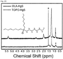
- Substitutable organic ligands may be oleic acid, mercaptopropionic acid (MPA), cysteamine, mercaptoacetic acid, trioctylphosphine (TOP), trioctylphosphine oxide (TOPO), octylamine, trioctyl amine, hexadecylamine, octanethiol, dodecanethiol, hexylphosphonic acid (HPA), tetradecylphosphonic acid (TDPA), or octylphosphinic acid (OPA) and FTIR and 1 H NMR after substituting with trioctylphosphine oxide (TOPO) and dodecanethiol were measured and spectra thoseof were compared ( see FIGS. 19 to 22 ).
- TOP trioctylphosphine
- TOPO trioctylphosphine oxide
- FTIR and 1 H NMR after substituting with trioc
- FIGS. 19 to 21 the heavily doping was maintained even after ligand substitution to exhibit absorption in a mid-infrared region so that it was confirmed that the ligand substitution of the quantum dot of the nonthiol ligand was easier than the thiol ligand of the related art in which the ligand substation was hard.
- the gray area of FIGS. 19 to 21 illustrate an area corresponding to a C-H vibration mode of carbon dioxide and the ligand.
- the HgS quantum dots prepared by the method of Example 1 were stably dispersed in a non-polar solvent. Thereafter, an excess of the inorganic ligand to be substituted was added to a polar solvent (n-methylformamide solution and deionized water) and then stirred with the non-polar solvent phase for 15 minutes to 1 day. After the quantum dots present in the nonpolar solvent were shifted to the polar solvent phase, stirring was stopped and the quantum dots were separated by centrifugation.
- a polar solvent n-methylformamide solution and deionized water
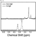
- a substitutable inorganic ligand may be a halogenide (Cl-, Br-, I-) and a cyanide (SCN-), but the FTIR and 1 H NMR after substitution with chloride ion (Cl - ) were measured to compare spectra thoseof ( See FIGS. 23 and 24 ).
- the characteristic of the quantum dots become more similar to the metal plasmons. Therefore, the change between the semiconductor and the metal in the nanomaterial may be measured optically (FTIR) and magnetically (EPR).
- FTIR optically
- EPR magnetically
- the change between the semiconductor and the metal in the nanomaterial was measured while filling electron doping in the HgS quantum dots prepared by the method of Example 1.
- Upper-level electron transition (1P e -1D e ) of the heavily doped HgS quantum dot was observed by consistently irradiating infrared rays on a nonthiol ligand quantum dot film formed on a surface of gold Au.
- FIG. 30 is a view illustrating an infrared absorbance spectrum of a colloidal HgS quantum dots to which a voltage is not applied.
Landscapes
- Chemical & Material Sciences (AREA)
- Organic Chemistry (AREA)
- Inorganic Chemistry (AREA)
- Engineering & Computer Science (AREA)
- Materials Engineering (AREA)
- Luminescent Compositions (AREA)
- Electroluminescent Light Sources (AREA)
Abstract
Description
- The present invention relates to an infrared device using electron transition between quantized energy levels, and more particularly, to quantum dot nanoparticles which comprise quantum dot cores and nonthiol ligands bonded to the core and emit infrared rays from electron transition between discrete energy levels in the band and an infrared device comprising the nanoparticles.
- A quantum dot is a nano-sized semiconductor substance and exhibits quantum confinement effect. When the quantum dot is stimulated by an energy such as light, the quantum dot emits light and a color of the emitted light varies depending on a size of the particle. That is, when the size of the substance is small so that a dimension of the substance is lowered, the property of the substance may vary depending on the dimension due to different electron state density and energy. When the quantum dot absorbs the light from an excitation source to reach an energy exited state, the quantum dot emits energy corresponding to an energy band gap of the quantum dot. Therefore, when a size and a composition of the quantum dot are controlled, an energy band gap is also controlled so that light from an ultraviolet region to a near infrared region may be emitted. However, it is very difficult to emit infrared rays, specifically, mid-infrared rays or far-infrared rays due to a large band gap of the quantum dot.
- In the meantime, generally, the quantum dot may be mainly prepared by two ways as follows. One of them is a lithographic method using a light source such as a laser and the other is a chemical wet method in which a precursor material is added to a solvent to grow crystals. Between two ways, according to the chemical wet method which synthesizes the quantum dots, uniformity of the size and the shape of the nanoparticles may be controlled by easier and cheaper processes than that of the lithographic method. Further, a choroidal quantum dot which is passivated with an organic ligand is not aggregated in a solution due to steric hindrance of the organic ligand, maintains a stable structure, and exhibits excellent luminescent characteristics by passivation of surface defects. However, the choroidal quantum dot which is stabilized by a thiol organic ligand of the related art has a disadvantage in that the ligand substitution for photoelectronic applications such as photodetectors and solar cells is not easy.
- (Patent Document 1) Korean Unexamined Patent Application Publication No.
10-2009-0114112 - The present inventors confirm that when discrete electron transition energy in a band of a quantum dot having a proportion of metal which is non-stoichiometrically higher than a proportion of chalcogen is used, infrared rays, particularly, mid-infrared rays or far-infrared rays are emitted, while searching an infrared device, and then complete the present invention.
- Therefore, the present invention is directed to providing non-stoichiometric quantum dot nanoparticles which comprise quantum dot cores and nonthiol ligands bonded to the core and emit infrared rays from electron transition between discrete energy levels in the band.
- Further, the present invention is directed to providing a producing method of non-stoichiometric colloidal quantum dot nanoparticles comprising nonthiol ligands.
- Furthermore, the present invention is directed to providing an infrared device comprising the non-stoichiometric quantum dot nanoparticles.
- An aspect of the present invention provides non-stoichiometric quantum dot nanoparticles which comprise quantum dot cores and nonthiol ligands bonded to the core and emit infrared rays from electron transition between discrete energy levels in the band.
- Further, another aspect of the present invention provides a producing method of non-stoichiometric colloidal quantum dot nanoparticles comprising (1) preparing a mercury (Hg) precursor solution by heating a mixture of a mercury (Hg) precursor and nonthiol ligands at 100 to 150°C; and (2) mixing the mercury (Hg) precursor solution and the chalcogen precursor solution, followed by heating at 40 to 120°C.
- Further, another aspect of the present invention provides an infrared device comprising the non-stoichiometric quantum dot nanoparticles.
- According to the present invention, an infrared device which emits infrared rays, particularly, mid-infrared rays or far-infrared rays, by using the electron transition between discrete energy levels in the band of quantum dots.
- Further, the non-stoichiometric quantum dots are prepared by containing nonthiol ligands so that as compared with thiol ligands of the related art, ligand substitution is very easy while maintaining the n-type doping of quantum dots.
-
-
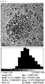
FIG. 1 is a view illustrating a transmission electron microscope (TEM) image and size distribution of HgS quantum dots having an average size of 3.7 nm prepared by a method of Example 1-1. -
FIG. 2 is a view illustrating a transmission electron microscope (TEM) image and size distribution of HgS quantum dots having an average size of 4.2 nm prepared by a method of Example 1-2. -
FIG. 3 is a view illustrating a transmission electron microscope (TEM) image and size distribution of HgS quantum dots having an average size of 5.6 nm prepared by a method of Example 1-3. -
FIG. 4 is a view illustrating a transmission electron microscope (TEM) image and size distribution of HgS quantum dots having an average size of 5.7 nm prepared by a method of Example 1-4. -
FIG. 5 is a view illustrating a transmission electron microscope (TEM) image and size distribution of HgS quantum dots having an average size of 8.5 nm prepared by a method of Example 1-5. -
FIG. 6 is a view illustrating a transmission electron microscope (TEM) image and size distribution of HgS quantum dots having an average size of 13.4 nm prepared by a method of Example 1-6. -
FIG. 7 is a view illustrating a transmission electron microscope (TEM) image and size distribution of HgS quantum dots having an average size of 15.1 nm prepared by a method of Example 1-7. -
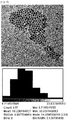
FIG. 8 is a view illustrating a transmission electron microscope (TEM) image and size distribution of HgS quantum dots having an average size of 18.2 nm prepared by a method of Example 1-8. -
FIG. 9 is a view illustrating an FT-IR absorbance spectrum according to a size of an HgS quantum dot according to Examples 1-4, 1-9 to 1-13. -
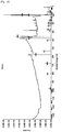
FIG. 10 is a view illustrating 1H NMR spectrum of (a) an oleylamine ligand bonded to an HgS quantum dot prepared by the method of Example 1 and (b) oleylamine which is not bonded to the HgS quantum dot. -
FIG. 11 is a view illustrating an X-ray diffraction (XRD) spectrum of HgS quantum dots having average sizes of (a) 5.7 nm and (b) 14.2 nm prepared by the method of Examples 1-4 and 1-13. -
FIG. 12 is a view illustrating Hg:S component proportion analysis of HgS quantum dots having an average size of 2.3 nm prepared by a method of Example 1-14 using an X-ray photoelectron spectroscopy (XPS). -
FIG. 13 is a view illustrating Hg:S component proportion analysis of HgS quantum dots having an average size of 4.5 nm prepared by a method of Example 1-15 using an XPS. -
FIG. 14 is a view illustrating Hg:S component proportion analysis of HgS quantum dots having an average size of 4.5 nm prepared by a method of Example 1-16 using an XPS. -
FIG. 15 is a view illustrating Hg:S component proportion analysis of HgS quantum dots having an average size of 4.9 nm prepared by a method of Example 1-17 using an XPS. -
FIG. 16 is a view illustrating Hg:S component proportion analysis of HgS quantum dots having an average size of 5.6 nm prepared by a method of Example 1-18 using an XPS. -
FIG. 17 is a view illustrating an electrical signal of infrared fluorescence generated when a heavily doped HgS quantum dot is irradiated with a visible light laser according to a time. -
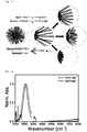
FIG. 18 is a conceptual view illustrating that a quantum dot comprising nonthiol ligand (OLA) is substituted with an organic (TOPO or DDT) or an inorganic (Cl) ligand. -
FIG. 19 illustrates an FTIR spectrum when oleylamine (OLA) which is nonthiol ligand is bonded to an HgS quantum dot and is substituted with dodecanethiol (DDT) which is an organic ligand, in which a gray area is an area which cannot be measured by a C-H vibration mode. -
FIG. 20 illustrates a 1H NMR spectrum when oleylamine (OLA) which is nonthiol ligand is bonded to an HgS quantum dot and is substituted with dodecanethiol (DDT) which is an organic ligand. -
FIG. 21 illustrates an FTIR spectrum when oleylamine (OLA) which is nonthiol ligand is bonded to an HgS quantum dot and is substituted with trioctylphosphineoxide (TOPO) which is an organic ligand, in which a gray area is an area which cannot be measured by a carbon dioxide and C-H vibration mode in the atmosphere. -
FIG. 22 illustrates a 1H NMR spectrum when oleylamine (OLA) which is nonthiol ligand is bonded to an HgS quantum dot and is substituted with trioctylphosphineoxide (TOPO) which is an organic ligand. -
FIG. 23 illustrates an FTIR spectrum when oleylamine (OLA) which is nonthiol ligand is bonded to an HgS quantum dot and is substituted with chlorine (CI) which is an inorganic ligand, in which a gray area is an area which cannot be measured by absorption of N-methylformamide (NMF) which is a polar solvent. -
FIG. 24 illustrates a 1H NMR spectrum when oleylamine (OLA) which is nonthiol ligands is bonded to an HgS quantum dot and is substituted with chlorine (CI) which is an inorganic ligand, in which * is a signal by a solvent (DMSO, water). -
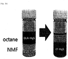
FIG. 25 is a view illustrating a process that the HgS quantum dot bonded to oleylamine which is dispersed in a non-polar solvent (octane) is substituted with chlorine which is an inorganic ligand to be shifted to a polar solvent. -
FIG. 26 is images of an optical microscope (a) and an FTIR microscope (b) when a heavily doped HgS quantum dot film surface is treated with S2- ion (right) and is not treated with S2- ion (left). -
FIG. 27 is an FTIR microscope image of a heavily doped nonthiol ligand HgS quantum dot and the illustration is an optical microscope image. -
FIG. 28 is a view illustrating an FTIR spectrum showing a process that 1Se-1Pe (S-P) electron transition and upper-level 1Pe-1De (P-D) electron transition are generated depending on a thickness of a quantum dot film. -
FIG. 29 is a view illustrating S-P, P-D transition energy prediction of band gap transition (1Sh-1Se) using k.p model. -
FIG. 30 is a view illustrating an infrared absorbance spectrum of non-stoichiometric colloidal quantum dots to which a voltage is not applied. -
FIG. 31 is a view illustrating an infrared absorbance spectrum of non-stoichiometric colloidal quantum dots by applying a negative voltage by an infrared device using an HgS quantum dot prepared by a method of Example 4. -
FIG. 32 is a view illustrating an infrared absorbance spectrum of non-stoichiometric colloidal quantum dots by applying a positive voltage using an infrared device using an HgS quantum dot prepared by a method of Example 4. - Hereinafter, the present invention will be described in detail.
- The present invention provides non-stoichiometric quantum dot nanoparticles which comprise quantum dot cores and nonthiol ligands bonded to the core and emit infrared rays from electron transition between discrete energy levels in the band.
- The quantum dot is a nano-sized semiconductor substance and exhibits quantum confinement effect. When the quantum dot absorbs the light from an excitation source to reach an energy excited state, the quantum dot emits energy corresponding to an energy band gap of the quantum dot. Therefore, when the size of the quantum dot is controlled, an energy band gap is controlled so that the light from an ultraviolet region to a near-infrared region may be emitted. However, it is very difficult to emit infrared rays, particularly, mid-infrared rays or far-infrared rays due to a large band gap of the quantum dot.
- The quantum dot nanoparticle according to the present invention may emit infrared rays of a specific wavelength, particularly, mid-infrared rays and far-infrared rays, through electron transition between discrete energy levels in a band, rather than electron transition between band gaps.
- The nonthiol ligands may be bonded to 1 mol of the core at a molar ratio of 1 to 100.
- Further, the energy level state of the quantum dot may be S, P, or D and desirably, may be IS, IP, or ID or higher.
- When the size of the quantum dot is controlled, an interval of the discrete energy levels in the band may be controlled.
- The discrete energy levels in the band are composed of an energy level filled with electrons and an energy level where electrons are emptied. In this case, when light higher than a gap of the above-described energy levels is applied, the electrons accept the light energy to be excited and leave holes in the place where the electrons escape. In this case, the electrons and the holes are bonded again to generate infrared rays, particularly mid-infrared rays or far-infrared rays.
- An average diameter of the quantum dots may be 1 to 20 nm and desirably, may be 3 to 15 nm. In this size, thermal stability and luminous efficiency may be maximized.
- Further, as the size of the quantum dot is increased, an infrared ray having a smaller wavenumber may be emitted from the electron transition between the discrete energy levels in the band. According to the exemplary embodiment of the present invention, a quantum dot having an average size of 17 to 19 nm exhibits an absorbance spectrum of approximately 800 to 1100 cm-1 and a quantum dot having an average size of 4 to 6 nm exhibits an absorbance spectrum of approximately 2100 to 2400 cm-1.
- The infrared ray may be a mid-infrared ray or far-infrared ray.
- The quantum dot may comprise cores and organic or inorganic ligands bonded to the core.
- The quantum dot cores may comprise a II-VI group semiconductor compound, a III-V group semiconductor compound, a IV-VI group semiconductor compound, a IV group element or compound, or a combination thereof. Specifically, the quantum dot cores may be CdS, CdSe, CdTe, ZnS, ZnSe, ZnTe, ZnO, HgS, HgSe, HgTe, CdSeS, CdSeTe, CdSTe, ZnSeS, ZnSeTe, ZnSTe, HgSeS, HgSeTe, HgSTe, CdZnS, CdZnSe, CdZnTe, CdHgS, CdHgSe, CdHgTe, HgZnS, HgZnSe, CdHgZnTe, CdZnSeS, CdZnSeTe, CdZnSTe, CdHgSeS, CdHgSeTe, CdHgSTe, HgZnSeS, HgZnSeTe, HgZnSTe; GaN, GaP, GaAs, GaSb, AlN, AlP, AlAs, AlSb, InN, InP, InAs, InSb, GaNP, GaNAs, GaNSb, GaPAs, GaPSb, AlNP, AlNAs, AlNSb, AlPAs, AlPSb, InNP, InNAs, InNSb, InPAs, InPSb, GaAlNP, GaAlNAs, GaAlNSb, GaAlPAs, GaAlPSb, GaInNP, GaInNAs, GaInNSb, GaInPAs, GaInPSb, InAlNP, InAlNAs, InAlNSb, InAlPAs, InAlPSb; SnS, SnSe, SnTe, PbS, PbSe, PbTe, SnSeS, SnSeTe, SnSTe, PbSeS, PbSeTe, PbSTe, SnPbS, SnPbSe, SnPbTe, SnPbSSe, SnPbSeTe, SnPbSTe; Si, Ge, SiC, or SiGe.
- The quantum dot cores may be mercury chalcogen nanoparticles and the mercury chalcogen may be HgS, HgSe, or HgTe.
- The ligand refers to a substance which is bonded to the nanocrystals so as not to aggregate the quantum dots to be fixed and stabilized. Further, the nonthiol ligand is a ligand which does not contain a thiol-group and refers to an organic or inorganic ligand which is bonded to the inorganic center, other than thiol. The choroidal quantum dot which is stabilized by a thiol organic ligand of the related art has a disadvantage in that the ligand substitution for photoelectronic applications such as photodetectors and solar cells is not easy. Therefore, when the nonthiol ligand, particularly, oleic acid or oleylamine is used, it has the advantage of maintaining the n-type doping of quantum dots and simultaneously facilitating ligand substitution.
- Specifically, the thiol ligands may be oleic acid, oleylamine, trioctylphosphine (TOP), trioctylphosphine oxide (TOPO), octylamine, trioctyl amine, hexadecylamine, hexylphosphonic acid (HPA), tetradecylphosphonic acid (TDPA), octylphosphinic acid (OPA), and desirably may be oleic acid or oleylamine, but is not limited thereto.
- Further, the present invention relates to a producing method of non-stoichiometric colloidal quantum dot nanoparticles comprising (1) a step of preparing a mercury (Hg) precursor solution by heating a mixture of a mercury (Hg) precursor and nonthiol ligands at 100 to 150°C; and (2) a step of mixing the mercury (Hg) precursor solution and the chalcogen precursor solution, followed by heating at 40 to 120°C.
- The producing method may further comprise a step of irradiating light to the non-stoichiometric colloidal quantum dots.
- The step (1) is a step of preparing the mercury precursor solution by reacting the mercury (Hg) precursor with nonthiol ligands.
- As a quantum dot synthesizing method, vapor deposition methods such as a metal organic chemical vapor deposition (MOCVD) or molecular beam epitaxy (MBE) are used to prepare the quantum dots or a chemical wet method which adds a precursor material to a solvent to grow crystals. According to the chemical wet method, when the crystals are grown, the solvent is naturally coordinated on a quantum dot crystal surface to be served as a dispersant to control the growth of the crystal. Therefore, according to the chemical wet method, uniformity of the size and the shape of the nanoparticles may be controlled by easier and cheaper processes than that of the metal organic chemical vapor deposition (MOCVD) or molecular beam epitaxy (MBE). Further, the quantum dots prepared by the chemical wet process are not used as the undiluted solution and a predetermined ligand is coordinated around the quantum dots for stabilization or convenience of use of the quantum dots.
- Specifically, the nonthiol ligands may be oleic acid, oleylamine, trioctylphosphine (TOP), trioctylphosphine oxide (TOPO), octylamine, trioctyl amine, hexadecylamine, hexylphosphonic acid (HPA), tetradecylphosphonic acid (TDPA), octylphosphinic acid (OPA), and desirably may be oleic acid or oleylamine, but is not limited thereto.
- The nonthiol ligands may be used at a molar ratio of 1 to 100 with respect to 1 mol of mercury (Hg). Therefore, when the used amount is less than 1 mol, the fixing effect of the quantum dots after the synthesis of the quantum dots is markedly deteriorated. As a result, the quantum effect is lost due to aggregation of the quantum dots in the solution and the effect of adding the ligand is reduced by half. Further, when the used amount exceeds 100 mol, the quantum dots may be re-aggregated due to the lowering of solubility.
- Such a reaction is performed by a method which is widely known in the field of the present invention. In the present invention, the reaction may be performed under a reaction condition at 100 to 150°C for 0.5 to 1.5 hours. When the reaction is performed out of the above condition, a solubility of a raw material is lowered or a solvent is evaporated so that a yield of the quantum dots is lowered. Therefore, it is desirable to maintain the above range.
- In step (2), the mercury (Hg) precursor solution and chalcogen precursor solution are mixed and then heated at 40 to 120°C to produce a colloidal quantum dot. As the chalcogen, S, Se, or Te is desirably used.
- The chalcogen is dissolved using a high boiling solvent, and a boiling point of the solvent is maintained in the range of 200 to 350°C. When the boiling point of the solution is lower than 200°C, the solubility of the chalcogen is low and the boiling point of the solution exceeds 350°C, it is not easy to select a solvent. The solvent may be octadecene, octadecylamine, hexadecene, pentadecene, tetradecene, octadecadiene, hexadecadiene, tetradecadiene, phenylether, diphenyl, paraffin, oleic acid, or hexadecane, but is not limited thereto.
- The chalcogen may be mixed at a molar ratio of 1 to 10, preferably 1 to 5, with respect to 1 mol of the mercury (Hg) metal. When the used amount of the chalcogen is lower than 1 mol, a yield of quantum dot is lowered and a characteristic of emitting in-band transition infrared ray having a specific wavelength is not exhibited. When the amount exceeds 5 mol, an amount of unreacted chalcogen is increased. However, the use of a little excess of chalcogen is advantageous for non-stoichiometric quantum dot synthesis which emits infrared rays, so that it is preferable to maintain the above range.
- In this case, the reaction is performed at 10 to 250°C, desirably, at 40 to 120°C which is significantly lower than 300 to 350°C which is a quantum dot preparing temperature of the related art. However, when the reaction temperature is lower than 40°C, the quantum dot is not prepared and the reaction temperature exceeds 120°C, the quantum dot is excessively grown so that the quantum effect cannot be achieved.
- Further, the present invention relates to an infrared device comprising the non-stoichiometric quantum dot nanoparticles.
- The infrared device may be used for a device which emits infrared rays, particularly mid-infrared rays or far-infrared rays. Specifically, the infrared device may be an infrared camera, an infrared detector, an infrared therapy device, an infrared communication device, an infrared solar cell, an infrared LED, an infrared laser, a gas sensor, or an infrared color filter, but is not limited thereto.
- Hereinafter, preferred embodiments will be suggested for better understanding of the present invention. However, the following embodiments are provided only for more understanding the present invention, and thus the present invention is not limited thereto.
- A mercury (Hg) precursor solution was prepared by dissolving 550 mg (2 mmol) of HgCl2 in 16 ml (48 mmol) of oleylamine and then being dehydrated in vacuum and heated at approximately 120°C for one hour.
- Simultaneously, a sulfur (S) precursor solution was prepared in another container by dissolving 0.57 mmol of thioacetamide or bis (trimethylsilyl) sulfide in octadecene or octadecylamine.
- Thereafter, the mercury (Hg) precursor solution and the sulfur (S) precursor solution were mixed and the mixture was heated at approximately 60°C. In this case, the reaction time was controlled to 32 minutes to adjust a size of the prepared quantum dot to be 3.7 nm. HgS quantum dots were prepared by injecting 10 ml of a nonpolar solvent of tetrachloroethylene or chloroform containing oleylamine into the reaction mixture and cooling to room temperature using cooling water to terminate the reaction.
- HgS quantum dots having various sizes were prepared by using the same method as Example 1-1 and adjusting used amounts of HgCl2, oleylamine, and sulfur precursor and reaction temperatures and times as represented in Table 1.
[Table 1] Exampl e Size of HgS quantu m dot (nm) HgCl2 Oleylamine S precurs (mmol) Temp. (°C) Reactio n Time (min) mg mmol ml mmol 1-2 4.2 160 0.6 8 24 0.086 90 16 1-3 5.6 550 2 16 48 0.6 70 32 1-4 5.7 80 0.3 8 24 0.045 110 32 1-5 8.5 80 0.3 8 24 0.178 70 4 1-6 13.4 40 0.15 4 12 0.086 80 32 1-7 15.1 40 0.15 4 12 0.270 120 4 1-8 18.2 40 0.15 4 12 0.356 120 4 1-9 2.3 40 0.15 4 12 0.023 70 16 1-10 4.5 80 0.15 8 24 0.045 90 32 1-11 7.0 80 0.3 8 24 0.057 120 32 1-12 8.6 40 0.3 4 12 0.106 110 4 1-13 14.2 40 0.15 4 12 0.356 110 4 1-14 2.3 40 0.15 4 12 0.029 70 4 1-15 4.5 160 0.6 8 24 0.086 90 16 1-16 4.5 550 2 16 48 0.407 70 32 1-17 4.9 80 0.3 8 24 0.045 90 32 1-18 5.6 80 0.3 8 24 0.045 110 32 - HgSe quantum dots were prepared by the same method as Example 1 except that a selenium (Se) precursor was used instead of the sulfur (S) precursor in Example 1.
- HgTe quantum dots were prepared by the same method as Example 1 except that a tellurium (Te) precursor was used instead of the sulfur (S) precursor in Example 1.
- An intensity of infrared fluorescence emitted from the quantum dot by irradiating ultraviolet, visible or infrared light sources to the HgS, HgSe or HgTe quantum dots prepared in Examples 1 to 3.
- An infrared device which reversibly controls a transmittance of a specific wavelength in accordance with an applied voltage was manufactured by coating the HgS, HgSe, or HgTe quantum dots prepared in Examples 1 to 3 on a chrome electrode in the form of a film. In this case, in order to apply the voltage to the quantum dots, the oleylamine ligand was substituted with a ligand in which a length of carbon is short and an electrolyte was 0.1 M tetrabutylammonium perchlorate. The transmittance of a specific wavelength was controlled by measuring the amount of change of the light reflected after interaction of the light incident on the voltage-applied quantum dot film and the substance.
- Transmission electron microscope (TEM) images and size distributions of HgS quantum dots having average sizes of 3.7 nm, 4.2 nm, 5.6 nm, 5.7 nm, 8.5 nm, 13.4 nm, 15.1 nm, and 18.2 nm which were prepared by the methods of Examples 1-1 to 1-8 were illustrated in
FIGS. 1 to 8 . - All the prepared HgS quantum dots form nanocrystals. In the case of a quantum dot having an average size of 18.2 nm, a size distribution was 8.7 to 33.8 nm and a standard deviation was 4.0 nm and in the case of a quantum dot having an average size of 3.7 nm, a size distribution was 2.2 to 6.1 nm and a standard deviation was 0.7 nm.
- As illustrated in the FT-IR absorbance spectrum (see
FIG. 9 ) according to the sizes of the HgS quantum dots prepared by the methods of Examples 1-4, 1-9 to 1-13, all the HgS quantum dots absorb light in the mid-infrared region or far-infrared region and as the average size of the quantum dots is larger, the absorbance spectrum exhibited a smaller wavenumber. Further, in the case of a quantum dot having an average size of 18.2 nm, an absorbance spectrum was approximately 800 to 1100 cm-1 and in the case of a quantum dot having an average size of 5.7 nm, an absorbance spectrum was approximately 2100 to 2400 cm-1. -
FIG. 10A illustrates a 1H NMR spectrum of an oleylamine ligand bonded to an HgS quantum dot when the quantum dots were prepared by the method of Example 1 andFIG. 10B illustrates a 1H NMR spectrum of an oleylamine ligand which is not bonded to an HgS quantum dot. - As illustrated in the X-ray diffraction (XRD) spectrum (see
FIG. 11 ) of the HgS quantum dots having an average size of (a) 5.7 nm and (b) 14.2 nm prepared by the methods of Examples 1-4 and 1-13, all the HgS quantum dots having the average sizes of 5.7 nm and 14.2 nm show crystallinity. Therefore, it is understood that the crystallinity of the quantum dot having a larger average size is clearer than the crystallinity of the quantum dot having a smaller average size. - An atomic content ratio of the quantum dots prepared by the method of Example 1 was measured by using a PHI X-tool system (ULVAC-PHI) and an X-ray photoelectron spectroscopy (XPS) using monochromatic Al Kα X-ray as an excitation source.
- It was confirmed that the atomic content of Hg in the element constituting the HgS quantum dot having the average size of 2.3 nm prepared by the method of Example 1-14 was 1.65 times higher than the atomic content of S. (see
FIG. 12 ). - Further, it was confirmed that the atomic content of Hg of the HgS quantum dot having the average size of 4.5 nm prepared by the method of Examples 1-15 and 1-16 was 1.56 to 1.67 times higher than the atomic content of S. (see
FIGS. 13 and14 ). - Further, it was confirmed that the atomic content of Hg of the HgS quantum dot having the average size of 4.9 nm prepared by the method of Example 1-17 was 2.15 times higher than the atomic content of S. (see
FIG. 15 ). - Further, it was confirmed that the atomic content of Hg of the HgS quantum dot having the average size of 5.6 nm prepared by the method of Example 1-18 was 1.44 times higher than the atomic content of S. (see
FIG. 16 ). - An electric signal of infrared fluorescence of a quantum dot film generated by irradiating a laser light source of a visible ray region to the HgS quantum dot prepared by the method of Example 1 was measured using an MCT detector (see
FIG. 17 ). The laser used in this case was 10 Hz, Nd:YAG nano pulse laser (532 nm). - The HgS quantum dots prepared by the method of Example 1 was stably dispersed in a non-polar solvent. An excess ligand to be substituted was added to the colloidal quantum dot, stirred for about 15 minutes, and the ligand-substituted quantum dots were separated by centrifugation.
- Substitutable organic ligands may be oleic acid, mercaptopropionic acid (MPA), cysteamine, mercaptoacetic acid, trioctylphosphine (TOP), trioctylphosphine oxide (TOPO), octylamine, trioctyl amine, hexadecylamine, octanethiol, dodecanethiol, hexylphosphonic acid (HPA), tetradecylphosphonic acid (TDPA), or octylphosphinic acid (OPA) and FTIR and 1H NMR after substituting with trioctylphosphine oxide (TOPO) and dodecanethiol were measured and spectra thoseof were compared (see
FIGS. 19 to 22 ). - In
FIGS. 19 to 21 , the heavily doping was maintained even after ligand substitution to exhibit absorption in a mid-infrared region so that it was confirmed that the ligand substitution of the quantum dot of the nonthiol ligand was easier than the thiol ligand of the related art in which the ligand substation was hard. The gray area ofFIGS. 19 to 21 illustrate an area corresponding to a C-H vibration mode of carbon dioxide and the ligand. - The HgS quantum dots prepared by the method of Example 1 were stably dispersed in a non-polar solvent. Thereafter, an excess of the inorganic ligand to be substituted was added to a polar solvent (n-methylformamide solution and deionized water) and then stirred with the non-polar solvent phase for 15 minutes to 1 day. After the quantum dots present in the nonpolar solvent were shifted to the polar solvent phase, stirring was stopped and the quantum dots were separated by centrifugation.
- A substitutable inorganic ligand may be a halogenide (Cl-, Br-, I-) and a cyanide (SCN-), but the FTIR and 1H NMR after substitution with chloride ion (Cl-) were measured to compare spectra thoseof (See
FIGS. 23 and24 ). - It was confirmed that the nonthiol ligand HgS quantum dots dispersed in the non-polar solvent (octane) were phase-shifted to a polar solvent (NMF) by the inorganic ligand substation (see
FIG. 25 ). This represents that when the nonthiol ligand is bonded to the quantum dots, the ligand substitution of the ligand of the quantum dots was easier than that of the thiol ligand of the related art. A gray area ofFIG. 23 is an area which cannot be measured by absorption of N-methylformamide (NMF) which is a polar solvent. - After forming a quantum dot film by heavily doping the HgS quantum dots prepared by the method of Example 1 on a CaF2 or ZnS, or ZnSe window, 2% solution of ammonium sulfide was applied on a partial area of the surface of the film to remove the heavy doping and measured with an optical microscope (see
FIG. 26A ) and an FTIR microscope (seeFIG. 26B ). - In
FIG. 26 , a proportion of chalcogen was locally higher than the metal so that the heavy doping was removed. Therefore, the band gap transition (1Se-1Pe) was restored to be a PN junction like structure formed of a single material. - As electrons fill the upper level of the quantum dots, the characteristic of the quantum dots become more similar to the metal plasmons. Therefore, the change between the semiconductor and the metal in the nanomaterial may be measured optically (FTIR) and magnetically (EPR).
- The change between the semiconductor and the metal in the nanomaterial was measured while filling electron doping in the HgS quantum dots prepared by the method of Example 1. Upper-level electron transition (1Pe-1De) of the heavily doped HgS quantum dot was observed by consistently irradiating infrared rays on a nonthiol ligand quantum dot film formed on a surface of gold Au.
- It was confirmed that an upper-level P-D transition may be formed in accordance with the thickness of the film through the optical microscope image (see illustration of
FIG. 27 ), the FTIR microscope image (seeFIG. 27 ), and spectra thoseof (seeFIG. 28 ). It was confirmed that S-P, P-D transition energy for band gap transition (1Sh-1Se) matches the experimental result using k.p model (seeFIG. 29 ). - Reversible change of the specific wavelength transmittance was measured by applying various voltages to the device manufactured by the method of Example 4.
FIG. 30 is a view illustrating an infrared absorbance spectrum of a colloidal HgS quantum dots to which a voltage is not applied. - When a negative voltage of 0 to -1.5 V was applied to the quantum dot film, the transmittance near 2500 cm-1 of the absorbance spectrum was lowered and shifted to a low wavelength region (see
FIG. 31 ). When a positive voltage of 0 to +1.0V was applied to the quantum dot film, the transmittance near 2500 cm-1 of the absorbance spectrum was increased and shifted to a high wavelength region (seeFIG. 32 ). By doing this, it was confirmed that when the voltage is changed, specific wavelength transmittance is reversibly changed. - As described above, the present invention has been described through Examples. It will be appreciated by those skilled in the art that the present invention as described above may be implemented into other specific forms without departing from the technical spirit thereof or essential characteristics. Therefore, it should be understood that the above-described examples are illustrative, but are not restrictive in all respects. The scope of the present invention is represented by the claims to be described below rather than the detailed description, and it is to be interpreted that the meaning and scope of the claims and all the changes or modified forms derived from the equivalents thereof come within the scope of the present invention.
Claims (17)
- Non-stoichiometric quantum dot nanoparticles comprising quantum dot cores and nonthiol ligands bonded to the core,
wherein infrared rays are emitted from electron transition between discrete energy levels in a band. - The non-stoichiometric quantum dot nanoparticles of claim 1, wherein the nonthiol ligand is bonded to 1 mol of the core at a molar ratio of 1 to 100.
- The non-stoichiometric quantum dot nanoparticles of claim 1, wherein the energy level of the quantum dot is a S, P, or D level.
- The non-stoichiometric quantum dot nanoparticles of claim 1, wherein the quantum dot has an average diameter of 1 to 20 nm.
- The non-stoichiometric quantum dot nanoparticles of claim 1, wherein the larger the size of the quantum dot is, the smaller wavenumber of the infrared rays is emitted.
- The non-stoichiometric quantum dot nanoparticles of claim 1, wherein the infrared ray is a mid-infrared ray or a far-infrared ray.
- The non-stoichiometric quantum dot nanoparticles of claim 1, wherein the quantum dot core is one or more selected from the group consisting of CdS, CdSe, CdTe, ZnS, ZnSe, ZnTe, ZnO, HgS, HgSe, HgTe, CdSeS, CdSeTe, CdSTe, ZnSeS, ZnSeTe, ZnSTe, HgSeS, HgSeTe, HgSTe, CdZnS, CdZnSe, CdZnTe, CdHgS, CdHgSe, CdHgTe, HgZnS, HgZnSe, CdHgZnTe, CdZnSeS, CdZnSeTe, CdZnSTe, CdHgSeS, CdHgSeTe, CdHgSTe, HgZnSeS, HgZnSeTe, HgZnSTe; GaN, GaP, GaAs, GaSb, AlN, AlP, AlAs, AlSb, InN, InP, InAs, InSb, GaNP, GaNAs, GaNSb, GaPAs, GaPSb, AlNP, AlNAs, AlNSb, AlPAs, AlPSb, InNP, InNAs, InNSb, InPAs, InPSb, GaAlNP, GaAlNAs, GaAlNSb, GaAlPAs, GaAlPSb, GaInNP, GaInNAs, GaInNSb, GaInPAs, GaInPSb, InAlNP, InAlNAs, InAlNSb, InAlPAs, InAlPSb; SnS, SnSe, SnTe, PbS, PbSe, PbTe, SnSeS, SnSeTe, SnSTe, PbSeS, PbSeTe, PbSTe, SnPbS, SnPbSe, SnPbTe, SnPbSSe, SnPbSeTe, SnPbSTe; Si, Ge, SiC, or SiGe.
- The non-stoichiometric quantum dot nanoparticles of claim 1, wherein the quantum dot core is a mercury-chalcogen nanocrystal.
- The non-stoichiometric quantum dot nanoparticles of claim 8, wherein the chalcogen of the nanocrystal is composed of an atomic ratio of 1 to 10 with respect to one mercury.
- The non-stoichiometric quantum dot nanoparticles of claim 1, wherein the nonthiol ligand is one or more selected from a group consisting of oleic acid, oleylamine, trioctylphosphine (TOP), trioctylphosphine oxide (TOPO), octylamine, trioctyl amine, hexadecylamine, hexylphosphonic acid (HPA), tetradecylphosphonic acid (TDPA), and octylphosphinic acid (OPA).
- A producing method of non-stoichiometric colloidal quantum dot nanoparticles, comprising:(1) preparing a mercury (Hg) precursor solution by heating a mixture of a mercury (Hg) precursor and nonthiol ligands to 100 to 150°C; and(2) mixing the mercury (Hg) precursor solution and the chalcogen precursor solution, followed by heating to 40 to 120°C.
- The producing method of claim 11, further comprising:
irradiating light to the colloidal quantum dot. - The producing method of claim 11, wherein in step (1), the nonthiol ligands are used at a molar ratio of 1 to 100 per 1 mol of mercury (Hg).
- The producing method of claim 11, wherein in step (2), a solvent of a chalcogen precursor solution is one or more selected from a group consisting of octadecene, octadecylamine, hexadecene, pentadecene, tetradecene, octadecadiene, hexadecadiene, tetradecadiene, phenylether, diphenyl, paraffin, oleic acid, and hexadecane.
- The producing method of claim 11, wherein in step (3), the chalcogen is used at a molar ratio of 1 to 10 per 1 mol of mercury (Hg).
- An infrared device comprising:
the non-stoichiometric quantum dot nanoparticles of claim 1. - The infrared device of claim 16, wherein the infrared device is an infrared camera, an infrared detector, an infrared therapy device, an infrared communication device, an infrared solar cell, an infrared LED, an infrared laser, a gas sensor, or an infrared color filter
Applications Claiming Priority (2)
| Application Number | Priority Date | Filing Date | Title |
|---|---|---|---|
| KR20160040301 | 2016-04-01 | ||
| PCT/KR2017/003566 WO2017171482A1 (en) | 2016-04-01 | 2017-03-31 | Infrared device using intra-band electron transition of non-stoichiometric colloidal quantum dots |
Publications (3)
| Publication Number | Publication Date |
|---|---|
| EP3438226A1 true EP3438226A1 (en) | 2019-02-06 |
| EP3438226A4 EP3438226A4 (en) | 2019-11-13 |
| EP3438226B1 EP3438226B1 (en) | 2025-06-04 |
Family
ID=59965020
Family Applications (1)
| Application Number | Title | Priority Date | Filing Date |
|---|---|---|---|
| EP17775906.5A Active EP3438226B1 (en) | 2016-04-01 | 2017-03-31 | Infrared device using intra-band electron transition of non-stoichiometric colloidal quantum dots |
Country Status (4)
| Country | Link |
|---|---|
| US (1) | US11066597B2 (en) |
| EP (1) | EP3438226B1 (en) |
| KR (1) | KR101971666B1 (en) |
| WO (1) | WO2017171482A1 (en) |
Cited By (1)
| Publication number | Priority date | Publication date | Assignee | Title |
|---|---|---|---|---|
| US11781906B2 (en) | 2020-03-05 | 2023-10-10 | Elbit Systems Ltd. | Self-adaptive electromagnetic energy attenuator |
Families Citing this family (12)
| Publication number | Priority date | Publication date | Assignee | Title |
|---|---|---|---|---|
| KR102153955B1 (en) * | 2018-03-22 | 2020-09-10 | 고려대학교 산학협력단 | Colloidal quantum dot for exhibiting mid-infrared intraband transition |
| KR102180493B1 (en) * | 2019-07-08 | 2020-11-18 | 한화시스템 주식회사 | Apparatus and method for infrared imaging |
| US11231365B2 (en) | 2019-07-08 | 2022-01-25 | Hanwha Systems Co., Ltd. | Apparatus and method for infrared imaging |
| KR102701725B1 (en) * | 2019-11-29 | 2024-09-03 | 주식회사 엘지화학 | Method for preparing quantum-dot |
| CN111662716B (en) * | 2020-06-28 | 2022-10-11 | 湖北理工学院 | A kind of neutral HgSe/CdSe/ZnSe double shell quantum dot and preparation method thereof |
| CN113998676A (en) * | 2021-12-10 | 2022-02-01 | 上海应用技术大学 | Method for preparing mercury selenide nanocrystalline by solvothermal method |
| CN114702960B (en) * | 2022-02-28 | 2022-12-27 | 北京理工大学 | Infrared quantum dot layer and preparation method thereof, infrared detector and preparation method thereof |
| CN119768484A (en) * | 2022-08-22 | 2025-04-04 | 高丽大学校算学协力团 | III-V colloidal quantum dots of heterogeneous ligands, preparation method of ink based on environmentally friendly solvents and application in optoelectronic devices |
| KR102858719B1 (en) * | 2022-08-22 | 2025-09-12 | 고려대학교 산학협력단 | III-V quantum dot comprising two different ligands, manufacturing method of environmently-friendly solvent-based ink using III-V quantum dot comprising two different ligands, and photoelectric devices fabricated using the same |
| KR102767825B1 (en) * | 2023-06-08 | 2025-02-17 | 고려대학교 산학협력단 | Non-toxic noble metal chalcogenide quantum dot thin film and preparing method of the same |
| GB2631786A (en) * | 2023-07-14 | 2025-01-15 | Quantum Science Ltd | Novel synthesis of colloidal quantum dot ink and applications in semiconductor devices |
| KR102871303B1 (en) * | 2024-04-02 | 2025-10-14 | 성균관대학교산학협력단 | Method for preparing surface-treated quantum dots using metal fluoride |
Family Cites Families (9)
| Publication number | Priority date | Publication date | Assignee | Title |
|---|---|---|---|---|
| US6344271B1 (en) * | 1998-11-06 | 2002-02-05 | Nanoenergy Corporation | Materials and products using nanostructured non-stoichiometric substances |
| KR100678291B1 (en) * | 2004-11-11 | 2007-02-02 | 삼성전자주식회사 | Light-receiving device using nanoparticles |
| US7906084B2 (en) * | 2007-05-30 | 2011-03-15 | Toyota Motor Engineering & Manufacturing North America, Inc. | Method for control of shape and size of PB-chalcogenide nanoparticles |
| KR100973945B1 (en) | 2008-04-29 | 2010-08-04 | 아주대학교산학협력단 | Quantum dot nanoparticles of core-multishell structure and uses thereof |
| US9318628B2 (en) * | 2011-05-20 | 2016-04-19 | The University Of Chicago | Mid-infrared photodetectors |
| KR101941173B1 (en) * | 2012-12-04 | 2019-01-22 | 삼성전자주식회사 | Nanoparticle passivated with a cationic metal-chalcogenide compound |
| KR102058371B1 (en) * | 2013-07-29 | 2020-02-07 | 엘지전자 주식회사 | Wearable glass-type device and control method thereof |
| US9481582B2 (en) * | 2013-11-27 | 2016-11-01 | Massachusetts Institute Of Technology | Nanocrystal synthesis |
| KR101632721B1 (en) | 2014-06-12 | 2016-06-29 | 한국과학기술원 | Graphene Quantum Dot in core-shell structure and method of producing thereof |
-
2017
- 2017-03-31 US US16/090,483 patent/US11066597B2/en active Active
- 2017-03-31 WO PCT/KR2017/003566 patent/WO2017171482A1/en not_active Ceased
- 2017-03-31 KR KR1020170041914A patent/KR101971666B1/en active Active
- 2017-03-31 EP EP17775906.5A patent/EP3438226B1/en active Active
Cited By (1)
| Publication number | Priority date | Publication date | Assignee | Title |
|---|---|---|---|---|
| US11781906B2 (en) | 2020-03-05 | 2023-10-10 | Elbit Systems Ltd. | Self-adaptive electromagnetic energy attenuator |
Also Published As
| Publication number | Publication date |
|---|---|
| EP3438226A4 (en) | 2019-11-13 |
| EP3438226B1 (en) | 2025-06-04 |
| KR101971666B1 (en) | 2019-04-23 |
| US20190119565A1 (en) | 2019-04-25 |
| US11066597B2 (en) | 2021-07-20 |
| KR20170113448A (en) | 2017-10-12 |
| WO2017171482A1 (en) | 2017-10-05 |
Similar Documents
| Publication | Publication Date | Title |
|---|---|---|
| US11066597B2 (en) | Intraband transition-based infrared device of nonstoichiometric quantum dots | |
| KR101525524B1 (en) | Nanocrystal particles and processes for synthesizing the same | |
| KR102252445B1 (en) | Quantum dots and devices including the same | |
| JP6587807B2 (en) | Nanocrystal particles, method for producing the same, and element | |
| KR101480475B1 (en) | Quantum dot stabilized by halogen salt and method for manufacturing the same | |
| RU2616080C2 (en) | Light source with quantum dots | |
| KR102337672B1 (en) | Emissive nanocrystal particle, method of preparing the same and device including emissive nanocrystal particle | |
| KR102446858B1 (en) | Quantum Dot Manufacturing Method | |
| KR101517094B1 (en) | Processes for synthesizing nanocrystals | |
| KR101644053B1 (en) | Processes for synthesizing nanocrystals and nanocrystal compositions | |
| KR101971586B1 (en) | Single electron occupied quantum dot and magnetic control method thereof | |
| EP2853578A1 (en) | Nanocrystal particles and processes for synthesizing the same | |
| US8790533B2 (en) | Method of etching semiconductor nanocrystals | |
| US20130146834A1 (en) | Quantum dot-matrix thin film and method of producing the same | |
| KR102398107B1 (en) | Method for Preparing Core/Shell Quantum Dot | |
| KR101719574B1 (en) | Passivated quantum dot and method for manufacturing the same | |
| KR102243744B1 (en) | Quantum-dot based on multi-shell structure including luminosity dopant | |
| EP4644509A1 (en) | Quantum dots, quantum dot preparation method, and electronic device comprising quantum dots | |
| US12473487B2 (en) | Method of preparing quantum dot, quantum dot, and electronic apparatus including the quantum dot | |
| KR102864844B1 (en) | Quantum-dot | |
| US20230028670A1 (en) | Method of manufacturing multi-component semiconductor nanocrystal, multi-component semiconductor nanocrystal, and quantum dot including the same | |
| US12215266B2 (en) | Nanocrystal particles and processes for synthesizing the same |
Legal Events
| Date | Code | Title | Description |
|---|---|---|---|
| STAA | Information on the status of an ep patent application or granted ep patent |
Free format text: STATUS: THE INTERNATIONAL PUBLICATION HAS BEEN MADE |
|
| PUAI | Public reference made under article 153(3) epc to a published international application that has entered the european phase |
Free format text: ORIGINAL CODE: 0009012 |
|
| STAA | Information on the status of an ep patent application or granted ep patent |
Free format text: STATUS: REQUEST FOR EXAMINATION WAS MADE |
|
| 17P | Request for examination filed |
Effective date: 20181001 |
|
| AK | Designated contracting states |
Kind code of ref document: A1 Designated state(s): AL AT BE BG CH CY CZ DE DK EE ES FI FR GB GR HR HU IE IS IT LI LT LU LV MC MK MT NL NO PL PT RO RS SE SI SK SM TR |
|
| AX | Request for extension of the european patent |
Extension state: BA ME |
|
| DAV | Request for validation of the european patent (deleted) | ||
| DAX | Request for extension of the european patent (deleted) | ||
| REG | Reference to a national code |
Ref country code: DE Ref legal event code: R079 Free format text: PREVIOUS MAIN CLASS: C09K0011080000 Ipc: C09K0011890000 |
|
| A4 | Supplementary search report drawn up and despatched |
Effective date: 20191011 |
|
| RIC1 | Information provided on ipc code assigned before grant |
Ipc: C09K 11/89 20060101AFI20191004BHEP Ipc: H01L 31/042 20140101ALI20191004BHEP Ipc: C01B 19/00 20060101ALI20191004BHEP Ipc: C01G 13/00 20060101ALI20191004BHEP Ipc: C09K 11/02 20060101ALI20191004BHEP |
|
| STAA | Information on the status of an ep patent application or granted ep patent |
Free format text: STATUS: EXAMINATION IS IN PROGRESS |
|
| 17Q | First examination report despatched |
Effective date: 20230911 |
|
| GRAP | Despatch of communication of intention to grant a patent |
Free format text: ORIGINAL CODE: EPIDOSNIGR1 |
|
| STAA | Information on the status of an ep patent application or granted ep patent |
Free format text: STATUS: GRANT OF PATENT IS INTENDED |
|
| RIC1 | Information provided on ipc code assigned before grant |
Ipc: H10F 19/00 20250101ALI20250228BHEP Ipc: C01G 13/00 20060101ALI20250228BHEP Ipc: C01B 19/00 20060101ALI20250228BHEP Ipc: C09K 11/02 20060101ALI20250228BHEP Ipc: C09K 11/89 20060101AFI20250228BHEP |
|
| INTG | Intention to grant announced |
Effective date: 20250318 |
|
| GRAS | Grant fee paid |
Free format text: ORIGINAL CODE: EPIDOSNIGR3 |
|
| GRAA | (expected) grant |
Free format text: ORIGINAL CODE: 0009210 |
|
| STAA | Information on the status of an ep patent application or granted ep patent |
Free format text: STATUS: THE PATENT HAS BEEN GRANTED |
|
| AK | Designated contracting states |
Kind code of ref document: B1 Designated state(s): AL AT BE BG CH CY CZ DE DK EE ES FI FR GB GR HR HU IE IS IT LI LT LU LV MC MK MT NL NO PL PT RO RS SE SI SK SM TR |
|
| REG | Reference to a national code |
Ref country code: GB Ref legal event code: FG4D |
|
| REG | Reference to a national code |
Ref country code: CH Ref legal event code: EP |
|
| REG | Reference to a national code |
Ref country code: DE Ref legal event code: R096 Ref document number: 602017089774 Country of ref document: DE |
|
| REG | Reference to a national code |
Ref country code: IE Ref legal event code: FG4D |
|
| REG | Reference to a national code |
Ref country code: NL Ref legal event code: MP Effective date: 20250604 |
|
| PG25 | Lapsed in a contracting state [announced via postgrant information from national office to epo] |
Ref country code: ES Free format text: LAPSE BECAUSE OF FAILURE TO SUBMIT A TRANSLATION OF THE DESCRIPTION OR TO PAY THE FEE WITHIN THE PRESCRIBED TIME-LIMIT Effective date: 20250604 Ref country code: FI Free format text: LAPSE BECAUSE OF FAILURE TO SUBMIT A TRANSLATION OF THE DESCRIPTION OR TO PAY THE FEE WITHIN THE PRESCRIBED TIME-LIMIT Effective date: 20250604 |
|
| REG | Reference to a national code |
Ref country code: LT Ref legal event code: MG9D |
|
| PG25 | Lapsed in a contracting state [announced via postgrant information from national office to epo] |
Ref country code: NO Free format text: LAPSE BECAUSE OF FAILURE TO SUBMIT A TRANSLATION OF THE DESCRIPTION OR TO PAY THE FEE WITHIN THE PRESCRIBED TIME-LIMIT Effective date: 20250904 Ref country code: GR Free format text: LAPSE BECAUSE OF FAILURE TO SUBMIT A TRANSLATION OF THE DESCRIPTION OR TO PAY THE FEE WITHIN THE PRESCRIBED TIME-LIMIT Effective date: 20250905 |
|
| PG25 | Lapsed in a contracting state [announced via postgrant information from national office to epo] |
Ref country code: PL Free format text: LAPSE BECAUSE OF FAILURE TO SUBMIT A TRANSLATION OF THE DESCRIPTION OR TO PAY THE FEE WITHIN THE PRESCRIBED TIME-LIMIT Effective date: 20250604 |
|
| PG25 | Lapsed in a contracting state [announced via postgrant information from national office to epo] |
Ref country code: BG Free format text: LAPSE BECAUSE OF FAILURE TO SUBMIT A TRANSLATION OF THE DESCRIPTION OR TO PAY THE FEE WITHIN THE PRESCRIBED TIME-LIMIT Effective date: 20250604 |
|
| PG25 | Lapsed in a contracting state [announced via postgrant information from national office to epo] |
Ref country code: HR Free format text: LAPSE BECAUSE OF FAILURE TO SUBMIT A TRANSLATION OF THE DESCRIPTION OR TO PAY THE FEE WITHIN THE PRESCRIBED TIME-LIMIT Effective date: 20250604 |
|
| PG25 | Lapsed in a contracting state [announced via postgrant information from national office to epo] |
Ref country code: RS Free format text: LAPSE BECAUSE OF FAILURE TO SUBMIT A TRANSLATION OF THE DESCRIPTION OR TO PAY THE FEE WITHIN THE PRESCRIBED TIME-LIMIT Effective date: 20250904 |
|
| PG25 | Lapsed in a contracting state [announced via postgrant information from national office to epo] |
Ref country code: LV Free format text: LAPSE BECAUSE OF FAILURE TO SUBMIT A TRANSLATION OF THE DESCRIPTION OR TO PAY THE FEE WITHIN THE PRESCRIBED TIME-LIMIT Effective date: 20250604 |
|
| PG25 | Lapsed in a contracting state [announced via postgrant information from national office to epo] |
Ref country code: NL Free format text: LAPSE BECAUSE OF FAILURE TO SUBMIT A TRANSLATION OF THE DESCRIPTION OR TO PAY THE FEE WITHIN THE PRESCRIBED TIME-LIMIT Effective date: 20250604 |
|
| PG25 | Lapsed in a contracting state [announced via postgrant information from national office to epo] |
Ref country code: PT Free format text: LAPSE BECAUSE OF FAILURE TO SUBMIT A TRANSLATION OF THE DESCRIPTION OR TO PAY THE FEE WITHIN THE PRESCRIBED TIME-LIMIT Effective date: 20251006 |
|
| REG | Reference to a national code |
Ref country code: AT Ref legal event code: MK05 Ref document number: 1800353 Country of ref document: AT Kind code of ref document: T Effective date: 20250604 |
|
| PG25 | Lapsed in a contracting state [announced via postgrant information from national office to epo] |
Ref country code: IS Free format text: LAPSE BECAUSE OF FAILURE TO SUBMIT A TRANSLATION OF THE DESCRIPTION OR TO PAY THE FEE WITHIN THE PRESCRIBED TIME-LIMIT Effective date: 20251004 |
|
| PG25 | Lapsed in a contracting state [announced via postgrant information from national office to epo] |
Ref country code: SM Free format text: LAPSE BECAUSE OF FAILURE TO SUBMIT A TRANSLATION OF THE DESCRIPTION OR TO PAY THE FEE WITHIN THE PRESCRIBED TIME-LIMIT Effective date: 20250604 Ref country code: AT Free format text: LAPSE BECAUSE OF FAILURE TO SUBMIT A TRANSLATION OF THE DESCRIPTION OR TO PAY THE FEE WITHIN THE PRESCRIBED TIME-LIMIT Effective date: 20250604 |
|
| PG25 | Lapsed in a contracting state [announced via postgrant information from national office to epo] |
Ref country code: CZ Free format text: LAPSE BECAUSE OF FAILURE TO SUBMIT A TRANSLATION OF THE DESCRIPTION OR TO PAY THE FEE WITHIN THE PRESCRIBED TIME-LIMIT Effective date: 20250604 |
|
| PG25 | Lapsed in a contracting state [announced via postgrant information from national office to epo] |
Ref country code: EE Free format text: LAPSE BECAUSE OF FAILURE TO SUBMIT A TRANSLATION OF THE DESCRIPTION OR TO PAY THE FEE WITHIN THE PRESCRIBED TIME-LIMIT Effective date: 20250604 |
|
| PG25 | Lapsed in a contracting state [announced via postgrant information from national office to epo] |
Ref country code: RO Free format text: LAPSE BECAUSE OF FAILURE TO SUBMIT A TRANSLATION OF THE DESCRIPTION OR TO PAY THE FEE WITHIN THE PRESCRIBED TIME-LIMIT Effective date: 20250604 Ref country code: SK Free format text: LAPSE BECAUSE OF FAILURE TO SUBMIT A TRANSLATION OF THE DESCRIPTION OR TO PAY THE FEE WITHIN THE PRESCRIBED TIME-LIMIT Effective date: 20250604 |
|
| PG25 | Lapsed in a contracting state [announced via postgrant information from national office to epo] |
Ref country code: IT Free format text: LAPSE BECAUSE OF FAILURE TO SUBMIT A TRANSLATION OF THE DESCRIPTION OR TO PAY THE FEE WITHIN THE PRESCRIBED TIME-LIMIT Effective date: 20250604 |
|
| REG | Reference to a national code |
Ref country code: DE Ref legal event code: R097 Ref document number: 602017089774 Country of ref document: DE |
|
| PLBE | No opposition filed within time limit |
Free format text: ORIGINAL CODE: 0009261 |
|
| STAA | Information on the status of an ep patent application or granted ep patent |
Free format text: STATUS: NO OPPOSITION FILED WITHIN TIME LIMIT |
|
| PG25 | Lapsed in a contracting state [announced via postgrant information from national office to epo] |
Ref country code: DK Free format text: LAPSE BECAUSE OF FAILURE TO SUBMIT A TRANSLATION OF THE DESCRIPTION OR TO PAY THE FEE WITHIN THE PRESCRIBED TIME-LIMIT Effective date: 20250604 |
|
| REG | Reference to a national code |
Ref country code: CH Ref legal event code: L10 Free format text: ST27 STATUS EVENT CODE: U-0-0-L10-L00 (AS PROVIDED BY THE NATIONAL OFFICE) Effective date: 20260416 |
|
| 26N | No opposition filed |
Effective date: 20260305 |