EP3437956A1 - Data integration and analysis system - Google Patents
Data integration and analysis system Download PDFInfo
- Publication number
- EP3437956A1 EP3437956A1 EP17773490.2A EP17773490A EP3437956A1 EP 3437956 A1 EP3437956 A1 EP 3437956A1 EP 17773490 A EP17773490 A EP 17773490A EP 3437956 A1 EP3437956 A1 EP 3437956A1
- Authority
- EP
- European Patent Office
- Prior art keywords
- analysis
- data
- indexes
- explanatory
- processing unit
- Prior art date
- Legal status (The legal status is an assumption and is not a legal conclusion. Google has not performed a legal analysis and makes no representation as to the accuracy of the status listed.)
- Granted
Links
Images



Classifications
-
- B—PERFORMING OPERATIONS; TRANSPORTING
- B61—RAILWAYS
- B61L—GUIDING RAILWAY TRAFFIC; ENSURING THE SAFETY OF RAILWAY TRAFFIC
- B61L15/00—Indicators provided on the vehicle or train for signalling purposes
- B61L15/0018—Communication with or on the vehicle or train
-
- B—PERFORMING OPERATIONS; TRANSPORTING
- B60—VEHICLES IN GENERAL
- B60L—PROPULSION OF ELECTRICALLY-PROPELLED VEHICLES; SUPPLYING ELECTRIC POWER FOR AUXILIARY EQUIPMENT OF ELECTRICALLY-PROPELLED VEHICLES; ELECTRODYNAMIC BRAKE SYSTEMS FOR VEHICLES IN GENERAL; MAGNETIC SUSPENSION OR LEVITATION FOR VEHICLES; MONITORING OPERATING VARIABLES OF ELECTRICALLY-PROPELLED VEHICLES; ELECTRIC SAFETY DEVICES FOR ELECTRICALLY-PROPELLED VEHICLES
- B60L15/00—Methods, circuits, or devices for controlling the traction-motor speed of electrically-propelled vehicles
- B60L15/40—Adaptation of control equipment on vehicle for remote actuation from a stationary place
-
- B—PERFORMING OPERATIONS; TRANSPORTING
- B61—RAILWAYS
- B61L—GUIDING RAILWAY TRAFFIC; ENSURING THE SAFETY OF RAILWAY TRAFFIC
- B61L25/00—Recording or indicating positions or identities of vehicles or trains or setting of track apparatus
- B61L25/02—Indicating or recording positions or identities of vehicles or trains
- B61L25/04—Indicating or recording train identities
-
- B—PERFORMING OPERATIONS; TRANSPORTING
- B61—RAILWAYS
- B61L—GUIDING RAILWAY TRAFFIC; ENSURING THE SAFETY OF RAILWAY TRAFFIC
- B61L27/00—Central railway traffic control systems; Trackside control; Communication systems specially adapted therefor
- B61L27/10—Operations, e.g. scheduling or time tables
- B61L27/16—Trackside optimisation of vehicle or train operation
-
- G—PHYSICS
- G06—COMPUTING OR CALCULATING; COUNTING
- G06N—COMPUTING ARRANGEMENTS BASED ON SPECIFIC COMPUTATIONAL MODELS
- G06N7/00—Computing arrangements based on specific mathematical models
-
- G—PHYSICS
- G08—SIGNALLING
- G08G—TRAFFIC CONTROL SYSTEMS
- G08G1/00—Traffic control systems for road vehicles
- G08G1/01—Detecting movement of traffic to be counted or controlled
-
- G—PHYSICS
- G08—SIGNALLING
- G08G—TRAFFIC CONTROL SYSTEMS
- G08G1/00—Traffic control systems for road vehicles
- G08G1/123—Traffic control systems for road vehicles indicating the position of vehicles, e.g. scheduled vehicles; Managing passenger vehicles circulating according to a fixed timetable, e.g. buses, trains, trams
- G08G1/127—Traffic control systems for road vehicles indicating the position of vehicles, e.g. scheduled vehicles; Managing passenger vehicles circulating according to a fixed timetable, e.g. buses, trains, trams to a central station ; Indicators in a central station
- G08G1/13—Traffic control systems for road vehicles indicating the position of vehicles, e.g. scheduled vehicles; Managing passenger vehicles circulating according to a fixed timetable, e.g. buses, trains, trams to a central station ; Indicators in a central station the indicator being in the form of a map
Definitions
- the technical field of the present invention relates to data integration and analysis regarding devices and apparatuses that operate at various places (for example, power generation facilities and air-conditioning systems), and in particular, regarding moving bodies the locations of which are momentarily vary such as railway vehicles.
- Patent Literature 1 Japanese Unexamined Patent Application Publication No. 2011-201336
- This publication cites the following as a problem: "Although status data regarding plural devices in a vehicle is compared, the data is separated into position factor components and device factor components, and abnormalities are detected, only data obtained from one vehicle is utilized, and data obtained from other vehicles is not utilized in this case.
- a technique is utilized in which the moving status values of the vehicle are stored and managed while being sorted in small sections, each moving status value is judged to be abnormal or not in comparison with the past information regarding the corresponding section, therefore the past information.
- a moving body including: a measurement apparatus that measures the statuses of various devices included in the moving body; a status monitoring apparatus that detects the occurrence of a failure using the status data of the various devices measured by the measurement apparatus; and a communication apparatus that transmits the type of the currently-happening failure and the status data of the various devices before and after the occurrence of the failure to the ground system, and receives an abnormality judgment result from the ground system
- the ground system includes: a communication apparatus that transmits data to the moving body and receives data from the moving body; an accumulation unit that accumulates the types of failures and the status data in the past about the moving body; and an abnormality diagnosis unit that analyzes the status data of failures in the past and at the same time outputs an abnormality diagnosis result obtained by judging whether the relevant failure is an abnormality or not
- the ground system further includes: an abnormality analysis database that stores the types of failures, abnormality diagnosis results, and status data in the past while they
- Patent Literature 1 Japanese Unexamined Patent Application Publication No. 2011-201336
- Patent Literature 1 Nevertheless, in the prior art described in Patent Literature 1, no method is disclosed for easily and in a short time extracting highly effective improvement measures and policies for all moving bodies or specified moving bodies, and performing feedback to a moving body for which the improvement measures are necessary.
- an aspect of the present invention is configured to provide a system for integrating and analyzing data of a moving body in which detection data that was detected by sensors mounted on the controlled devices of the moving body is gathered and a performance improvement index for the moving body is extracted from the detection data, wherein the system is characterized in that: correlation analysis is performed using an explanatory index generated from the operation status of the controlled devices, based on the performance index information for the moving body and the operation status of the controlled devices, using the performance index information for the moving body as a desired index; a data analysis central apparatus gathers the analysis results for each moving body; and clustering analysis is performed, whereby an effective explanatory index for performance index improvement for each moving body is extracted, and the effective explanatory index is applied only to the moving body.
- a railway vehicle is taken up as an example of a moving body, and a data integration and analysis system the object of which is to save the consumption energy of the railway vehicle will be explained as an embodiment with reference to the accompanying drawings.
- an example of a moving body is not limited to a railway vehicle, and any of an automobile, a construction machine, an elevator, a marine vessel, and an airplane can be adopted as an example of a moving body.
- the object of data analysis is not limited to the energy saving of a moving body but the object can be set to the improvement of comfort such as the ride quality of the moving body, or the improvement of the reliability for decreasing the failures of the devices of the moving body can be set to the object of the data analysis, or an index including a combination of the above improvements can be set to the object.
- the object of data analysis is not limited to the energy saving of a moving body but the object can be set to the improvement of comfort such as the ride quality of the moving body, or the improvement of the reliability for decreasing the failures of the devices of the moving body can be set to the object of the data analysis, or an index including a combination of the above improvements can be set to the object.
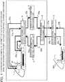
- Fig. 1 shows that the system according to the first embodiment includes a railway vehicle 1 and a data central analysis apparatus 2 as the entirety of a data integration and analysis system for a railway vehicle.
- the railway vehicle 1 includes: a driver 10; a control platform 7; a device control apparatus 9 for controlling devices such as the doors, toilets, brakes, and the like of the railway vehicle 1; a vehicle information control processing unit 4; a vehicle data analysis processing unit 3; a support information setting processing unit 5; and a data transmission processing unit 6.
- the vehicle information control processing unit 4, the vehicle data analysis processing unit 3, and the support information setting processing unit 5 are mounted on a certain device of the railway vehicle 1 or on an independent device, and the device containing these units is disposed in a device room or in an underfloor space of a specified vehicle of the railway vehicle 1.
- the vehicle information control processing unit 4 receives signals 21a such as a vehicle driving command signal from the control platform 7, signals 23a such as a device status monitoring signal from the device control apparatus 9, and support information 30a from the support information setting processing unit 5, and outputs signals 22a such as a vehicle driving support signal to the control platform 7, signals 24a such as a device status changing parameter signal to the device control apparatus 9, and a vehicle status monitoring signal 25a to the vehicle data analysis processing unit 3.
- the vehicle data analysis processing unit 3 receives the vehicle status monitoring signal 25a from the vehicle information control processing unit 4, and outputs a vehicle data analysis result 26a to the data transmission processing unit 6.
- the support information setting processing unit 5 receives support condition information 29a from the data transmission processing unit 6, and outputs support information 30a to the vehicle information control processing unit 4.
- the data transmission processing unit 6 transmits the vehicle data analysis result 26a input from the vehicle data analysis processing unit 3 to the data central analysis apparatus 2 by wireless as a vehicle data analysis result 27a, and outputs support condition information 28a received from the data central analysis apparatus 2 by wireless to the support information setting processing unit 5 as the support condition information 29a.
- the data central analysis apparatus 2 receives the vehicle data analysis result 27a transmitted from the data transmission processing unit 6 of the railway vehicle 1 by wireless, and outputs the support condition information 28a to the data transmission processing unit 6 of the railway vehicle 1.
- the data central analysis apparatus 2 is a system configured to perform not only the data transmission of the support condition information 28a and the vehicle data analysis result 27a with the railway vehicle 1 but also configured to perform the data transmission of support condition information 28b and a vehicle data analysis result 29b with another railway vehicle 300.
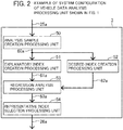
- the vehicle data analysis processing unit 3 includes: an analysis sample creation processing unit 50; an explanatory index creation processing unit 51; a desired index creation processing unit 52; a regression analysis processing unit 53; and a representative index selection processing unit 54.
- the vehicle status monitoring signal 25a output from the vehicle information processing unit 4 is input into the analysis sample creation processing unit 50, and the analysis sample creation processing unit 50 outputs the time history signal 60a of the vehicle status monitoring signal sampled for data analysis to the explanatory index creation processing unit 51 and the desired index creation processing unit 52.
- the explanatory index creation processing unit 51 creates explanatory indexes used for regression analysis from the time history signal 60a of the input vehicle status monitoring signal, and outputs an explanatory index signal 61a to the regression analysis processing unit 53.
- the desired index creation processing unit 52 creates desired indexes used for the regression analysis from the time history signal 60a of the input vehicle status monitoring signal, and transmits a desired index signal 62a to the regression analysis processing unit 53.
- the regression analysis processing unit 53 performs the regression analysis using the input the explanatory index signal 61a and the input the desired index signal 62a, and outputs a regression analysis result 63a to the representative index selection processing unit 54.
- the representative index selection processing unit 54 receives the regression analysis result 63a, and outputs the vehicle data analysis result 26a to the data transmission processing unit 6. An example of the processing contents of the vehicle data analysis processing unit will be explained in detail later.
- the data central analysis apparatus 2 includes: a data reception processing unit 70; a representative index integration processing unit 71; a clustering processing unit 72; a judgment processing unit 73; a support condition setting processing unit 74; and data transmission processing unit 75.
- data analysis results 27a, 27b, ⁇ , 27n of respective railway vehicles output from data transmission processing units 6 are input into the data reception processing unit 70, and the vehicle data analysis results 80a of the respective railway vehicles are output to the representative index integration processing unit 71.
- the representative index integration processing unit 71 receives the vehicle data analysis results 80a of the respective railway vehicles, and outputs an integration index result 81a to the clustering processing unit 72.
- the clustering processing unit 72 receives the integration processing result 81a, outputs a clustering processing result 82a to the judgment processing unit 73.
- the judgment processing unit 73 receives the clustering processing result 82a, and outputs a judgment result 83a to the support condition setting processing unit 74.
- the support condition setting processing unit 74 receives the judgment result 83a, and outputs support condition information 84a to the data transmission processing unit 75.
- the data transmission processing unit 75 receives the support condition information 84a, and outputs pieces of the support condition information 28a, 28b, ⁇ , 28n to the data transmission processing units 6 of the respective vehicles that need the support condition information 84a.
- An example of the processing contents of the data central analysis apparatus 2 will be explained in detail later.
- the data central analysis apparatus 2 can be installed on any of an operation command office, a maintenance base, and the like on the ground.
- the data central analysis apparatus 2 can be installed on a representative vehicle of the plural railway vehicles.
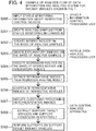
- the vehicle information control processing unit 4 receives status monitoring information about respective control devices mounted on the railway vehicle 1 (at step S200) .
- the analysis sample creation processing unit 50 in the vehicle data analysis processing unit creates analysis samples based on vehicle velocity information about the velocity of the railway vehicle, position signals such as station information about a station where the vehicle is located, and time information included in this status monitoring information (at step S201). For example, the analysis sample creation processing unit 50 creates status monitoring information regarding the vehicle between any two adjacent stations as one analysis sample using the velocity of the railway vehicle and the station information.
- the desired index creation processing unit 52 in the vehicle data analysis processing unit creates desired indexes on the basis of the analysis samples (at step S202). For example, the consumed electric energy of the driving system or the auxiliary machine of the vehicle between any two adjacent stations as one analysis sample is set to one desired index.
- the consumed electric energy of the driving system or the auxiliary machine of the vehicle between any two adjacent stations as one analysis sample is set to one desired index.
- traveling distances regarding plural combinations of two adjacent stations are different from one another, it is recommended that a value obtained by dividing every consumed electric energy by the relevant traveling distance is set to a desired index, that is, every consumed electric energy is normalized by the relevant traveling distance.
- explanatory index creation processing unit 51 in the vehicle data analysis processing unit explanatory indexes are created on the basis of the analysis samples (at step S203).
- the operation ratio showing each piece of status monitoring information regarding any two adjacent stations (that is, in the case of taking the traveling velocity of the vehicle as an example, the time ratio showing a probability that the operation traveling velocity falls within 0 and 25 %, within 25 and 50 %, within 50 and 75 %, or within 75 and 100 % relative to the maximum operation traveling velocity 100 %) is calculated, and this operation ratio is set to one explanatory index.
- this operation ratio is set to one explanatory index.
- traveling times regarding plural combinations of two adjacent stations are different from one another, it is recommended that a value obtained by dividing every operation ratio by the relevant traveling time is set to an explanatory index, that is, every explanatory index is normalized by the relevant traveling time.
- explanatory indexes that become representative indexes and have high correlations with desired indexes are extracted (at step S205) .
- explanatory indexes that have high correlations with consumed electric energies that are desired indexes are extracted using correlation relations, and the correlation coefficients and regression coefficients (absolute values) are recorded as sets respectively, and a predefined number of top explanatory indexes are listed as representative indexes.
- the data reception processing unit 70 in the data central analysis apparatus 2 receives the representative indexes of the respective railway vehicles, and the representative index integration processing unit 71 aggregates the received representative indexes of the respective railway vehicles (at step S206).
- the clustering processing unit 72 in the data central analysis apparatus 2 performs clustering processing for calculating reference values used for the judgment of the tendencies of the representative indexes of the respective railway vehicles from the aggregated representative indexes (the clustering processing is, for example, processing in which the correlation coefficients and regression coefficients of the respective explanatory indexes with desired variables are prepared in advance, the correlation coefficients and regression coefficients of the respective explanatory indexes A, B, C, and so on are plotted on the correlation coefficient axis and regression axis, and the representative indexes are classified into subsets based on the respective explanatory variables A, B, C, and so on (at step S207).
- the support condition setting processing unit 74 in the data central analysis apparatus 2 extracts railway vehicles and the support conditions for the railway vehicles respectively on the basis of the clustering processing result (at step S208).
- the explanatory index A is applied to all railway vehicles A, ⁇ , N that are data analysis targets.
- a support condition that the explanatory index B is applied to only railway vehicles A, B, and C that are data analysis targets is calculated.
- the support information setting processing unit, etc. of each railway vehicle that is a support target the relevant support is performed on each railway vehicle itself (at step S209).
- Fig. 5 shows the time history waveforms of a consumed electric energy 80, which is a desired index, and an explanatory index A 81 between a station A and a station B, and the consumed electric energy 80 is successively accumulated while the railway vehicle is traveling between the station A and the station B.
- a consumed electric energy 84 per traveling distance accumulated at the station B is set to one sample of the desired indexes created at step S202 used for regression analysis.
- a first threshold 86 and a second threshold 87 are set in an explanatory index A, and the explanatory index A is separated into three ranges, that is, a range 1 that is below the first threshold 86, a range 2 that is between the first threshold 86 and the second threshold 87, and a range 3 that is above the second threshold 87.
- ratios of time periods during which the explanatory index A exist in the respective ranges (ranges 1 to 3) relatively to the traveling time of the railway vehicle are set to explanatory indexes, and this time the range 1 of the explanatory index A is set to one sample of the explanatory indexes created at step S203.
- regression analysis 82 the above indexes are extracted regarding plural combinations of two adjacent stations, and the regression analysis 82 is performed at step S204. Successively, a correlation coefficient between the range 1 of the explanatory index A and the consumed electric energy of the desired index is calculated and a regression coefficient is calculated from a regression line 83, and the correlation coefficient and the regression coefficient are output.
- the execution of the regression analysis 82 can be done every time the railway vehicle stops at stations or can be done at predefined time intervals or at predefined traveling distances. Furthermore, a ratio and ranges used for dividing an explanatory variable can be set in advance.
- an explanatory index can be a composite explanatory index obtained by multiplying plural explanatory indexes together, and for example, it is conceivable that data analysis is performed by setting an explanatory index to a ratio of both range 1 of the explanatory index A and range 1 of an explanatory index B being satisfied.
- a representative index 100 includes: an organization ID 101 that identifies the relevant railway vehicle; an analysis time period 102 of the representative index; explanatory indexes 103 that are selected as important indexes; correlation coefficients 104 corresponding to the respective explanatory indexes 103; and regression coefficients 105 corresponding to the respective explanatory indexes 103.
- the number of the explanatory indexes 103 has an upper limit number set in advance, and the explanatory indexes 103 are put in order on the basis of their correlation coefficients.
- each of representative indexes gathered from the respective railway vehicles are normalized by the number of railway vehicles that are collection targets from which each of the representative indexes is collected.
- Explanatory indexes 150 applied to all the railway vehicles and explanatory indexes 151 applied to specified railway vehicles are judged on the basis of a normalized frequency threshold 152 that is set in advance.
- Representative explanatory indexes A, B, ⁇ , N that exceed the threshold 152 are selected as candidates for an explanatory index 150 that is applied to all the railway vehicles, and representative explanatory indexes C, ⁇ that underrun the threshold 152 are selected as candidates for an explanatory index 151 that is applied to the specified railway vehicles.
- Fig. 8 shows relationships 120 between correlation coefficients and regression coefficients of the respective railway vehicles about explanatory indexes A121, B122, and N123 selected as explanatory index candidates to be applied to all the railway vehicles from representative indexes selected from the respective railway vehicles.
- the explanatory indexes A121 and the explanatory indexes N123 are selected as representative indexes in the respective railway vehicles, and their correlation coefficients are high.
- the explanatory indexes B122 are selected in the respective railway vehicles as representative indexes, the correlation coefficients of the explanatory indexes B122 vary.
- explanatory indexes applied to the respective vehicles are selected among these explanatory indexes A121, B122, and N123 in the following way.
- a correlation coefficient threshold 125 is predefined in advance, and the numbers of the respective explanatory indexes the correlation coefficients of which exceed the predefined threshold 125 of correlation coefficient are extracted.
- the ratios of the numbers of explanatory indexes exceeding the threshold 125 are calculated, and explanatory indexes the ratios of which exceeds a ratio threshold predefined in advance are set as targets.
- the explanatory indexes included in the index group are not set as index targets. Furthermore, the priorities of the explanatory indexes exceeding the ratio threshold are determined on the basis of centroid distances 126a and 126b that are determined by the correlation coefficients and regression coefficients of the explanatory indexes.
- the centroid distances 126a and 126b determined by the correlation coefficients and regression coefficients can be calculated by adding weights to the respective correlation coefficients and regression coefficients.
- the priorities of explanatory index candidates applied to the specified railway vehicles can also be determined by a similar method to the abovementioned method. Furthermore, in the case where the explanatory indexes applied to all the railway vehicles as well as the explanatory indexes applied to the specified railway vehicles are applied to a certain railway vehicle, the explanatory indexes applied to all the railway vehicles can be applied to the certain railway vehicle, and then the explanatory indexes applied to the specified railway vehicles can be applied to the certain railway vehicle, or the order of the abovementioned procedures can be reversed. Alternatively, priorities can be determined on the basis of the centroid distances determined by the correlation coefficients and regression coefficients of respective explanatory indexes.
Landscapes
- Engineering & Computer Science (AREA)
- Physics & Mathematics (AREA)
- Mechanical Engineering (AREA)
- General Physics & Mathematics (AREA)
- Theoretical Computer Science (AREA)
- Evolutionary Computation (AREA)
- Software Systems (AREA)
- Computational Mathematics (AREA)
- Mathematical Analysis (AREA)
- Mathematical Optimization (AREA)
- Pure & Applied Mathematics (AREA)
- Computing Systems (AREA)
- General Engineering & Computer Science (AREA)
- Mathematical Physics (AREA)
- Data Mining & Analysis (AREA)
- Artificial Intelligence (AREA)
- Power Engineering (AREA)
- Transportation (AREA)
- Algebra (AREA)
- Radar, Positioning & Navigation (AREA)
- Remote Sensing (AREA)
- Electric Propulsion And Braking For Vehicles (AREA)
- Train Traffic Observation, Control, And Security (AREA)
- Traffic Control Systems (AREA)
Abstract
Description
- The technical field of the present invention relates to data integration and analysis regarding devices and apparatuses that operate at various places (for example, power generation facilities and air-conditioning systems), and in particular, regarding moving bodies the locations of which are momentarily vary such as railway vehicles.
- The background art of a technology field regarding the present invention is disclosed by Japanese Unexamined Patent Application Publication No.
2011-201336
(Refer to the paragraphs [0006], [0007], and [0008] of Patent Literature 1) . And as a solution means for the above problem, the following and the like are disclosed:
"A moving body including: a measurement apparatus that measures the statuses of various devices included in the moving body; a status monitoring apparatus that detects the occurrence of a failure using the status data of the various devices measured by the measurement apparatus; and a communication apparatus that transmits the type of the currently-happening failure and the status data of the various devices before and after the occurrence of the failure to the ground system, and receives an abnormality judgment result from the ground system, wherein the ground system includes: a communication apparatus that transmits data to the moving body and receives data from the moving body; an accumulation unit that accumulates the types of failures and the status data in the past about the moving body; and an abnormality diagnosis unit that analyzes the status data of failures in the past and at the same time outputs an abnormality diagnosis result obtained by judging whether the relevant failure is an abnormality or not, and the ground system further includes: an abnormality analysis database that stores the types of failures, abnormality diagnosis results, and status data in the past while they are associated with one another; and an abnormality occurrence prediction unit that outputs an abnormality judgment result by comparing the type of failure transmitted from the moving body at the time the failure occurs and status data before and after the failure with the types of failures and status data in the past that are stored in the abnormality analysis database, and the communication apparatus of the ground system transmits the abnormality judgment result to the moving body (Refer to the paragraph [0009] of Patent Literature 1). - Patent Literature 1: Japanese Unexamined Patent Application Publication No.
2011-201336 - Nevertheless, in the prior art described in
Patent Literature 1, no method is disclosed for easily and in a short time extracting highly effective improvement measures and policies for all moving bodies or specified moving bodies, and performing feedback to a moving body for which the improvement measures are necessary. - In order to solve the above problem, an aspect of the present invention is configured to provide a system for integrating and analyzing data of a moving body in which detection data that was detected by sensors mounted on the controlled devices of the moving body is gathered and a performance improvement index for the moving body is extracted from the detection data, wherein the system is characterized in that: correlation analysis is performed using an explanatory index generated from the operation status of the controlled devices, based on the performance index information for the moving body and the operation status of the controlled devices, using the performance index information for the moving body as a desired index; a data analysis central apparatus gathers the analysis results for each moving body; and clustering analysis is performed, whereby an effective explanatory index for performance index improvement for each moving body is extracted, and the effective explanatory index is applied only to the moving body.
- According to the abovementioned measures, it becomes possible that highly effective improvement measures for all moving bodies or specified moving bodies are extracted easily and in a short time, and by feeding back these improvement measures to moving bodies for which these improvement measures are necessary, the performances of the target moving bodies can be improved.
-
-
Fig. 1 is a configuration example of the entirety of a data integration and analysis system for railway vehicles according to a first embodiment. -
Fig 2 is an example of the system configuration of a vehicle data analysis processing unit shown inFig. 1 . -
Fig. 3 is an example of the system configuration of a data central analysis apparatus shown inFig. 1 . -
Fig. 4 is an example of an analysis flow of the data integration and analysis system for railway vehicles shown inFig. 1 . -
Fig. 5 is an example of analysis processing of a vehicle data analysis processing unit shown inFig. 2 . -
Fig. 6 is an example of an analysis processing result of a vehicle data analysis processing unit shown inFig. 2 . -
Fig. 7 is an example of a selection method of explanatory index candidates performed by a data central analysis apparatus shown inFig. 3 . -
Fig. 8 is an example of a selection method of the priorities of explanatory indexes using the explanatory index candidates shown inFig. 7 . - Hereinafter, a railway vehicle is taken up as an example of a moving body, and a data integration and analysis system the object of which is to save the consumption energy of the railway vehicle will be explained as an embodiment with reference to the accompanying drawings. Here, an example of a moving body is not limited to a railway vehicle, and any of an automobile, a construction machine, an elevator, a marine vessel, and an airplane can be adopted as an example of a moving body. In addition, the object of data analysis is not limited to the energy saving of a moving body but the object can be set to the improvement of comfort such as the ride quality of the moving body, or the improvement of the reliability for decreasing the failures of the devices of the moving body can be set to the object of the data analysis, or an index including a combination of the above improvements can be set to the object. Furthermore, through all the drawings, components that have common functions are given the same reference, and redundant explanations about the components will be omitted.
- First, a configuration example of the entirety of a system according to a first embodiment will be explained with reference to
Fig. 1. Fig. 1 shows that the system according to the first embodiment includes arailway vehicle 1 and a datacentral analysis apparatus 2 as the entirety of a data integration and analysis system for a railway vehicle. Therailway vehicle 1 includes: adriver 10; a control platform 7; adevice control apparatus 9 for controlling devices such as the doors, toilets, brakes, and the like of therailway vehicle 1; a vehicle informationcontrol processing unit 4; a vehicle dataanalysis processing unit 3; a support information setting processing unit 5; and a data transmission processing unit 6. Here, it is conceivable that the vehicle informationcontrol processing unit 4, the vehicle dataanalysis processing unit 3, and the support information setting processing unit 5 are mounted on a certain device of therailway vehicle 1 or on an independent device, and the device containing these units is disposed in a device room or in an underfloor space of a specified vehicle of therailway vehicle 1. - Next, the flows of signals between the respective apparatuses and the respective processing units will be explained. First, the vehicle information
control processing unit 4 receivessignals 21a such as a vehicle driving command signal from the control platform 7, signals 23a such as a device status monitoring signal from thedevice control apparatus 9, and supportinformation 30a from the support information setting processing unit 5, and outputs signals 22a such as a vehicle driving support signal to the control platform 7, signals 24a such as a device status changing parameter signal to thedevice control apparatus 9, and a vehiclestatus monitoring signal 25a to the vehicle dataanalysis processing unit 3. The vehicle dataanalysis processing unit 3 receives the vehiclestatus monitoring signal 25a from the vehicle informationcontrol processing unit 4, and outputs a vehicle data analysis result 26a to the data transmission processing unit 6. The support information setting processing unit 5 receivessupport condition information 29a from the data transmission processing unit 6, and outputssupport information 30a to the vehicle informationcontrol processing unit 4. The data transmission processing unit 6 transmits the vehicle data analysis result 26a input from the vehicle dataanalysis processing unit 3 to the datacentral analysis apparatus 2 by wireless as a vehicle data analysis result 27a, and outputssupport condition information 28a received from the datacentral analysis apparatus 2 by wireless to the support information setting processing unit 5 as thesupport condition information 29a. The datacentral analysis apparatus 2 receives the vehicledata analysis result 27a transmitted from the data transmission processing unit 6 of therailway vehicle 1 by wireless, and outputs thesupport condition information 28a to the data transmission processing unit 6 of therailway vehicle 1. Furthermore, the datacentral analysis apparatus 2 is a system configured to perform not only the data transmission of thesupport condition information 28a and the vehicle data analysis result 27a with therailway vehicle 1 but also configured to perform the data transmission ofsupport condition information 28b and a vehicle data analysis result 29b with anotherrailway vehicle 300. - Next, the system configuration of the vehicle data analysis processing unit will be explained with reference to
Fig. 2 . The vehicle dataanalysis processing unit 3 includes: an analysis samplecreation processing unit 50; an explanatory indexcreation processing unit 51; a desired indexcreation processing unit 52; a regressionanalysis processing unit 53; and a representative indexselection processing unit 54. In the vehicle dataanalysis processing unit 3, the vehiclestatus monitoring signal 25a output from the vehicleinformation processing unit 4 is input into the analysis samplecreation processing unit 50, and the analysis samplecreation processing unit 50 outputs thetime history signal 60a of the vehicle status monitoring signal sampled for data analysis to the explanatory indexcreation processing unit 51 and the desired indexcreation processing unit 52. The explanatory indexcreation processing unit 51 creates explanatory indexes used for regression analysis from thetime history signal 60a of the input vehicle status monitoring signal, and outputs anexplanatory index signal 61a to the regressionanalysis processing unit 53. The desired indexcreation processing unit 52 creates desired indexes used for the regression analysis from thetime history signal 60a of the input vehicle status monitoring signal, and transmits a desiredindex signal 62a to the regressionanalysis processing unit 53. The regressionanalysis processing unit 53 performs the regression analysis using the input theexplanatory index signal 61a and the input the desiredindex signal 62a, and outputs a regression analysis result 63a to the representative indexselection processing unit 54. The representative indexselection processing unit 54 receives theregression analysis result 63a, and outputs the vehicle data analysis result 26a to the data transmission processing unit 6. An example of the processing contents of the vehicle data analysis processing unit will be explained in detail later. - Next, the system configuration of the data central analysis apparatus will be explained with reference to
Fig. 3 . The datacentral analysis apparatus 2 includes: a datareception processing unit 70; a representative indexintegration processing unit 71; aclustering processing unit 72; ajudgment processing unit 73; a support conditionsetting processing unit 74; and datatransmission processing unit 75. In the datacentral analysis apparatus 2,data analysis results reception processing unit 70, and the vehicledata analysis results 80a of the respective railway vehicles are output to the representative indexintegration processing unit 71. The representative indexintegration processing unit 71 receives the vehicledata analysis results 80a of the respective railway vehicles, and outputs anintegration index result 81a to theclustering processing unit 72. Theclustering processing unit 72 receives theintegration processing result 81a, outputs aclustering processing result 82a to thejudgment processing unit 73. Thejudgment processing unit 73 receives theclustering processing result 82a, and outputs ajudgment result 83a to the support condition settingprocessing unit 74. The support condition settingprocessing unit 74 receives thejudgment result 83a, and outputs supportcondition information 84a to the datatransmission processing unit 75. The datatransmission processing unit 75 receives thesupport condition information 84a, and outputs pieces of thesupport condition information support condition information 84a. An example of the processing contents of the datacentral analysis apparatus 2 will be explained in detail later. Here, the datacentral analysis apparatus 2 can be installed on any of an operation command office, a maintenance base, and the like on the ground. Alternatively, the datacentral analysis apparatus 2 can be installed on a representative vehicle of the plural railway vehicles. - Next, the analysis flow of the data integration and analysis system will be explained with reference to
Fig. 4 . First, the vehicle informationcontrol processing unit 4 receives status monitoring information about respective control devices mounted on the railway vehicle 1 (at step S200) . Next, the analysis samplecreation processing unit 50 in the vehicle data analysis processing unit creates analysis samples based on vehicle velocity information about the velocity of the railway vehicle, position signals such as station information about a station where the vehicle is located, and time information included in this status monitoring information (at step S201). For example, the analysis samplecreation processing unit 50 creates status monitoring information regarding the vehicle between any two adjacent stations as one analysis sample using the velocity of the railway vehicle and the station information. Next, the desired indexcreation processing unit 52 in the vehicle data analysis processing unit creates desired indexes on the basis of the analysis samples (at step S202). For example, the consumed electric energy of the driving system or the auxiliary machine of the vehicle between any two adjacent stations as one analysis sample is set to one desired index. Here, in the case where traveling distances regarding plural combinations of two adjacent stations are different from one another, it is recommended that a value obtained by dividing every consumed electric energy by the relevant traveling distance is set to a desired index, that is, every consumed electric energy is normalized by the relevant traveling distance. Next, in the explanatory indexcreation processing unit 51 in the vehicle data analysis processing unit, explanatory indexes are created on the basis of the analysis samples (at step S203). For example, as one analysis sample, the operation ratio showing each piece of status monitoring information regarding any two adjacent stations (that is, in the case of taking the traveling velocity of the vehicle as an example, the time ratio showing a probability that the operation traveling velocity falls within 0 and 25 %, within 25 and 50 %, within 50 and 75 %, or within 75 and 100 % relative to the maximumoperation traveling velocity 100 %) is calculated, and this operation ratio is set to one explanatory index. Here, in the case where traveling times regarding plural combinations of two adjacent stations are different from one another, it is recommended that a value obtained by dividing every operation ratio by the relevant traveling time is set to an explanatory index, that is, every explanatory index is normalized by the relevant traveling time. Next, in the regressionanalysis processing unit 53 in the vehicle data analysis processing unit, regression analysis is performed on the basis of the desired indexes and the explanatory indexes (at step S204). Next, in the representative indexselection processing unit 54 in the vehicle data analysis processing unit, explanatory indexes that become representative indexes and have high correlations with desired indexes are extracted (at step S205) . For example, explanatory indexes that have high correlations with consumed electric energies that are desired indexes are extracted using correlation relations, and the correlation coefficients and regression coefficients (absolute values) are recorded as sets respectively, and a predefined number of top explanatory indexes are listed as representative indexes. Next, the datareception processing unit 70 in the datacentral analysis apparatus 2 receives the representative indexes of the respective railway vehicles, and the representative indexintegration processing unit 71 aggregates the received representative indexes of the respective railway vehicles (at step S206). Next, theclustering processing unit 72 in the datacentral analysis apparatus 2 performs clustering processing for calculating reference values used for the judgment of the tendencies of the representative indexes of the respective railway vehicles from the aggregated representative indexes (the clustering processing is, for example, processing in which the correlation coefficients and regression coefficients of the respective explanatory indexes with desired variables are prepared in advance, the correlation coefficients and regression coefficients of the respective explanatory indexes A, B, C, and so on are plotted on the correlation coefficient axis and regression axis, and the representative indexes are classified into subsets based on the respective explanatory variables A, B, C, and so on (at step S207). Next, the support condition settingprocessing unit 74 in the datacentral analysis apparatus 2 extracts railway vehicles and the support conditions for the railway vehicles respectively on the basis of the clustering processing result (at step S208). For example, the explanatory index A is applied to all railway vehicles A, ···, N that are data analysis targets. Alternately, a support condition that the explanatory index B is applied to only railway vehicles A, B, and C that are data analysis targets is calculated. Next, in the support information setting processing unit, etc. of each railway vehicle that is a support target, the relevant support is performed on each railway vehicle itself (at step S209). - Next, an example of analysis processing performed by the vehicle data analysis processing unit will be explained with reference to
Fig. 5. Fig. 5 shows the time history waveforms of a consumedelectric energy 80, which is a desired index, and anexplanatory index A 81 between a station A and a station B, and the consumedelectric energy 80 is successively accumulated while the railway vehicle is traveling between the station A and the station B. A consumedelectric energy 84 per traveling distance accumulated at the station B is set to one sample of the desired indexes created at step S202 used for regression analysis. In addition, afirst threshold 86 and asecond threshold 87 are set in an explanatory index A, and the explanatory index A is separated into three ranges, that is, arange 1 that is below thefirst threshold 86, arange 2 that is between thefirst threshold 86 and thesecond threshold 87, and arange 3 that is above thesecond threshold 87. In the regression analysis, ratios of time periods during which the explanatory index A exist in the respective ranges (ranges 1 to 3) relatively to the traveling time of the railway vehicle are set to explanatory indexes, and this time therange 1 of the explanatory index A is set to one sample of the explanatory indexes created at step S203. Inregression analysis 82, the above indexes are extracted regarding plural combinations of two adjacent stations, and theregression analysis 82 is performed at step S204. Successively, a correlation coefficient between therange 1 of the explanatory index A and the consumed electric energy of the desired index is calculated and a regression coefficient is calculated from aregression line 83, and the correlation coefficient and the regression coefficient are output. Here, the execution of theregression analysis 82 can be done every time the railway vehicle stops at stations or can be done at predefined time intervals or at predefined traveling distances. Furthermore, a ratio and ranges used for dividing an explanatory variable can be set in advance. In addition, an explanatory index can be a composite explanatory index obtained by multiplying plural explanatory indexes together, and for example, it is conceivable that data analysis is performed by setting an explanatory index to a ratio of bothrange 1 of the explanatory index A andrange 1 of an explanatory index B being satisfied. - Next, an example of the representative indexes selected by the vehicle data analysis processing unit will be explained with reference to
Fig. 6 . InFig. 6 , arepresentative index 100 includes: an organization ID 101 that identifies the relevant railway vehicle; an analysis time period 102 of the representative index;explanatory indexes 103 that are selected as important indexes;correlation coefficients 104 corresponding to the respectiveexplanatory indexes 103; andregression coefficients 105 corresponding to the respectiveexplanatory indexes 103. The number of theexplanatory indexes 103 has an upper limit number set in advance, and theexplanatory indexes 103 are put in order on the basis of their correlation coefficients. - Next, an example of a selection method of explanatory index candidates performed by the data
central analysis apparatus 2 will be explained with reference toFig. 7 . InFig. 7 , each of representative indexes gathered from the respective railway vehicles are normalized by the number of railway vehicles that are collection targets from which each of the representative indexes is collected.Explanatory indexes 150 applied to all the railway vehicles andexplanatory indexes 151 applied to specified railway vehicles are judged on the basis of a normalizedfrequency threshold 152 that is set in advance. Representative explanatory indexes A, B, ···, N that exceed thethreshold 152 are selected as candidates for anexplanatory index 150 that is applied to all the railway vehicles, and representative explanatory indexes C, ··· that underrun thethreshold 152 are selected as candidates for anexplanatory index 151 that is applied to the specified railway vehicles. - Next, an example of a method for selecting priorities of explanatory indexes performed by the data
central analysis apparatus 2 will be explained with reference toFig. 8. Fig. 8 showsrelationships 120 between correlation coefficients and regression coefficients of the respective railway vehicles about explanatory indexes A121, B122, and N123 selected as explanatory index candidates to be applied to all the railway vehicles from representative indexes selected from the respective railway vehicles. The explanatory indexes A121 and the explanatory indexes N123 are selected as representative indexes in the respective railway vehicles, and their correlation coefficients are high. On the contrary, although the explanatory indexes B122 are selected in the respective railway vehicles as representative indexes, the correlation coefficients of the explanatory indexes B122 vary. In this case, explanatory indexes applied to the respective vehicles are selected among these explanatory indexes A121, B122, and N123 in the following way. First, acorrelation coefficient threshold 125 is predefined in advance, and the numbers of the respective explanatory indexes the correlation coefficients of which exceed thepredefined threshold 125 of correlation coefficient are extracted. Next, the ratios of the numbers of explanatory indexes exceeding thethreshold 125 are calculated, and explanatory indexes the ratios of which exceeds a ratio threshold predefined in advance are set as targets. Here, just like anindex group 124 of the explanatory indexes B122, if an index group includes a small number of selected indexes and the ratio of the number is smaller than the ratio threshold, the explanatory indexes included in the index group are not set as index targets. Furthermore, the priorities of the explanatory indexes exceeding the ratio threshold are determined on the basis ofcentroid distances centroid distances - As described above, according to this embodiment, it is possible that highly effective improvement measures for reducing consumed electric energies are extracted easily and in a short time for all railway vehicles that are moving bodies or for specified railway vehicles, and by feeding these improvement measures back to railway vehicles that need these improvement measures, the performances of the target railway vehicles can be improved.
-
- 1: Railway Vehicle
- 2: Data Central Analysis Apparatus
- 3: Vehicle Data Analysis Processing Unit
- 4: Vehicle Information Control Processing Unit
- 5: Support Information Setting Processing Unit
- 6: Data Transmission Processing Unit
- 7: Control Platform
- 9: Device Control Apparatus
- 10: Driver
- 21a: Signals such as Vehicle Driving Command Signal
- 22a: Signals such as Vehicle Driving Support Signal
- 23a: Signals such as Device Status Monitoring Signal
- 24a: Signals such as Device Status Changing Parameter Signal
- 25a: Vehicle Status Monitoring Signal
- 26a: Vehicle Data Analysis Result
- 27a: Vehicle Data Analysis Result
- 28a: Support Condition Information
- 29a: Support Condition Information
- 30a: Support Information
- 31a: Vehicle Data Analysis Result
- 32: Support Data
- 50: Analysis Sample Creation Processing Unit
- 51: Explanatory Index Creation Processing Unit
- 52: Desired Index Creation Processing Unit
- 53: Regression Analysis Processing Unit
- 54: Representative Index Selection Processing Unit
- 60a: Time History Signal of Vehicle Status Monitoring Signal
- 61a: Explanatory Index Signal
- 62a: Desired Index Signal
- 63a: Regression Analysis Result
- 70: Vehicle Data Reception Processing Unit
- 71: Representative Index Integration Processing Unit
- 72: Clustering Processing Unit
- 73: Judgment Processing Unit
- 74: Support Condition Setting Processing Unit 75: Data Transmission Processing Unit
- 80a: Vehicle Data Analysis Results of Respective Vehicles
- 81a: Integration Index Result
- 82a: Clustering Processing Result
- 83a: Judgment Result
- 84a: Support Condition Information
- 300: Railway Vehicle
Claims (6)
- A data integration and analysis system in which detection data that is detected by sensors for detecting the operation statuses of controlled devices mounted on a plurality of moving bodies is gathered, and indexes for improving the performances of the moving bodies are extracted from the detection data,
wherein each of the plurality of moving bodies includes a vehicle data analysis processing unit that performs correlation analysis between a plurality of desired indexes that show the performance of each of the plurality of moving bodies and a plurality of explanatory indexes that show the statuses of the controlled devices generated from the detection data,
wherein the data integration and analysis system includes a data central analysis apparatus that gathers the correlation analysis result from the vehicle data analysis processing unit included in each of the plurality of moving bodies and extracts explanatory indexes that have large correlations with the desired indexes on the basis of the plurality of correlation analysis results, and
wherein the data central analysis apparatus applies the extracted explanatory indexes to the moving bodies. - The data integration and analysis system according to claim 1,
wherein the explanatory indexes that are effective for the performance improvement of the respective moving bodies are extracted and simultaneously classified into explanatory indexes that are effectively usable for all the moving bodies and explanatory indexes each of which is effectively usable for only specified moving bodies. - The data integration and analysis system according to claim 1 or claim 2,
wherein the desired indexes are set to the consumed electric energies of devices mounted on the relevant moving body, the comfort of the relevant moving body, the reliability of the relevant moving body, or a combination thereof. - The data integration and analysis system according to any of claim 1, claim 2, and claim 3,
wherein the correlation analysis performed by the vehicle data analysis processing unit is performed every constant time interval, every constant traveling distance, or every traveling distance between any two adjacent railroad stations. - The data integration and analysis system according to any of claim 1 to claim 4,
wherein the data analysis central apparatus is prepared on the ground or on a specified moving body. - The data integration and analysis system according to any of claim 1 to claim 5,
wherein apparatuses or facilities the installation locations of which are fixed in space become targets of data analysis instead of the moving bodies.
Applications Claiming Priority (2)
| Application Number | Priority Date | Filing Date | Title |
|---|---|---|---|
| JP2016069941 | 2016-03-31 | ||
| PCT/JP2017/000912 WO2017168940A1 (en) | 2016-03-31 | 2017-01-13 | Data integration and analysis system |
Publications (3)
| Publication Number | Publication Date |
|---|---|
| EP3437956A1 true EP3437956A1 (en) | 2019-02-06 |
| EP3437956A4 EP3437956A4 (en) | 2019-12-04 |
| EP3437956B1 EP3437956B1 (en) | 2025-02-26 |
Family
ID=59963978
Family Applications (1)
| Application Number | Title | Priority Date | Filing Date |
|---|---|---|---|
| EP17773490.2A Active EP3437956B1 (en) | 2016-03-31 | 2017-01-13 | Data integration and analysis system |
Country Status (3)
| Country | Link |
|---|---|
| EP (1) | EP3437956B1 (en) |
| JP (1) | JP6619083B2 (en) |
| WO (1) | WO2017168940A1 (en) |
Families Citing this family (2)
| Publication number | Priority date | Publication date | Assignee | Title |
|---|---|---|---|---|
| JP6897438B2 (en) * | 2017-09-06 | 2021-06-30 | 富士通株式会社 | Information processing equipment, information processing systems and programs |
| CN109255953B (en) * | 2018-09-19 | 2020-11-03 | 江苏本能科技有限公司 | Region-based movable vehicle distribution display method and system |
Family Cites Families (10)
| Publication number | Priority date | Publication date | Assignee | Title |
|---|---|---|---|---|
| JP2002109690A (en) * | 2000-10-02 | 2002-04-12 | Nissan Motor Co Ltd | Remote maintenance device and method |
| US8538611B2 (en) * | 2003-01-06 | 2013-09-17 | General Electric Company | Multi-level railway operations optimization system and method |
| JP4193779B2 (en) * | 2004-09-22 | 2008-12-10 | 株式会社デンソー | Vehicle failure diagnosis method, failure diagnosis system, in-vehicle device, failure analysis device, failure diagnosis device |
| JP4761276B2 (en) * | 2008-07-10 | 2011-08-31 | 東芝エレベータ株式会社 | Abnormality diagnosis system for passenger conveyor |
| JP5297272B2 (en) * | 2009-06-11 | 2013-09-25 | 株式会社日立製作所 | Device abnormality monitoring method and system |
| EP2538332B1 (en) * | 2010-02-15 | 2020-04-01 | Nec Corporation | Fault cause extraction apparatus,fault cause extraction method and program recording medium |
| JP5416630B2 (en) * | 2010-03-24 | 2014-02-12 | 株式会社日立製作所 | Moving object abnormality judgment support system |
| JP2013213692A (en) * | 2012-03-30 | 2013-10-17 | Fujitsu Ten Ltd | Energy consumption calculation system and energy consumption calculation method |
| JP6222841B2 (en) * | 2014-03-25 | 2017-11-01 | 三菱重工業株式会社 | Operation management device, train control method and program |
| JP6279375B2 (en) * | 2014-03-25 | 2018-02-14 | 三菱重工業株式会社 | VEHICLE CONTROL DEVICE, TRANSPORTATION SYSTEM, VEHICLE CONTROL METHOD, AND PROGRAM |
-
2017
- 2017-01-13 JP JP2018508410A patent/JP6619083B2/en active Active
- 2017-01-13 WO PCT/JP2017/000912 patent/WO2017168940A1/en not_active Ceased
- 2017-01-13 EP EP17773490.2A patent/EP3437956B1/en active Active
Also Published As
| Publication number | Publication date |
|---|---|
| EP3437956B1 (en) | 2025-02-26 |
| JP6619083B2 (en) | 2019-12-11 |
| JPWO2017168940A1 (en) | 2019-03-22 |
| EP3437956A4 (en) | 2019-12-04 |
| WO2017168940A1 (en) | 2017-10-05 |
Similar Documents
| Publication | Publication Date | Title |
|---|---|---|
| JP6889057B2 (en) | Information processing equipment, information processing methods and computer programs | |
| AU2011353672B2 (en) | Data improvement system and method | |
| KR101880353B1 (en) | System for prognosticating failure of elevator | |
| AU2013320505B2 (en) | Method for diagnosing railroad components of a railroad network for rail transport | |
| CN101362568B (en) | Elevator abnormity diagnostic system | |
| CN112141069B (en) | Health management system of braking and air supply system for motor train unit | |
| EP2937258A1 (en) | Traffic control system | |
| CN105045256A (en) | Rail traffic real-time fault diagnosis method and system based on data comparative analysis | |
| US8849475B1 (en) | Systems and method for managing sensors in a vehicle | |
| WO2011118290A1 (en) | System for supporting determination of abnormality of moving object | |
| CN108960478B (en) | Vehicle part reliability determination system and method | |
| JP2010117864A (en) | Parking-lot information provision system | |
| CN106600047A (en) | Method for fault identification and early warning of air conditioners in passenger compartments of motor train unit based on BP neural network | |
| RU2754286C1 (en) | Method for sensory analysis, control system containing computer software product for sensory analysis, passenger counting system and vehicle for transporting passengers, in particular, in rail and road traffic | |
| KR20190083029A (en) | System and method of diagnosing defect of components of railway vehicle | |
| EP2464556B1 (en) | Method and electronic device to monitor the status of components of railway vehicles | |
| EP3437956B1 (en) | Data integration and analysis system | |
| KR20200058132A (en) | Railway vehicle major component and system diagnosis apparatus | |
| JP7229133B2 (en) | Train occupancy management system and train occupancy management method | |
| KR100740577B1 (en) | Automatic train operation system of electric train and method of realizing automatic train operation using this system | |
| CN110809280A (en) | Detection and early warning method and device for railway wireless network quality | |
| CN104712734B (en) | Monitoring unit for a drive unit of a rail vehicle | |
| EP3718942A1 (en) | Power meter based monitoring of elevator usage | |
| EP3459810B1 (en) | Method for predicting a failure of a sensor | |
| EP3955707A1 (en) | Method and system for predicting a failure probability of a component of an x-ray system |
Legal Events
| Date | Code | Title | Description |
|---|---|---|---|
| STAA | Information on the status of an ep patent application or granted ep patent |
Free format text: STATUS: THE INTERNATIONAL PUBLICATION HAS BEEN MADE |
|
| PUAI | Public reference made under article 153(3) epc to a published international application that has entered the european phase |
Free format text: ORIGINAL CODE: 0009012 |
|
| STAA | Information on the status of an ep patent application or granted ep patent |
Free format text: STATUS: REQUEST FOR EXAMINATION WAS MADE |
|
| 17P | Request for examination filed |
Effective date: 20180919 |
|
| AK | Designated contracting states |
Kind code of ref document: A1 Designated state(s): AL AT BE BG CH CY CZ DE DK EE ES FI FR GB GR HR HU IE IS IT LI LT LU LV MC MK MT NL NO PL PT RO RS SE SI SK SM TR |
|
| AX | Request for extension of the european patent |
Extension state: BA ME |
|
| DAV | Request for validation of the european patent (deleted) | ||
| DAX | Request for extension of the european patent (deleted) | ||
| A4 | Supplementary search report drawn up and despatched |
Effective date: 20191107 |
|
| RIC1 | Information provided on ipc code assigned before grant |
Ipc: B61L 27/00 20060101ALI20191031BHEP Ipc: G06N 7/00 20060101ALI20191031BHEP Ipc: B61L 15/00 20060101ALI20191031BHEP Ipc: B61L 25/04 20060101AFI20191031BHEP Ipc: G08G 1/01 20060101ALI20191031BHEP Ipc: B60L 15/40 20060101ALI20191031BHEP Ipc: G08G 1/13 20060101ALI20191031BHEP |
|
| STAA | Information on the status of an ep patent application or granted ep patent |
Free format text: STATUS: EXAMINATION IS IN PROGRESS |
|
| 17Q | First examination report despatched |
Effective date: 20211025 |
|
| REG | Reference to a national code |
Ref country code: DE Ref legal event code: R079 Free format text: PREVIOUS MAIN CLASS: B61L0025040000 Ref country code: DE Ref legal event code: R079 Ref document number: 602017088017 Country of ref document: DE Free format text: PREVIOUS MAIN CLASS: B61L0025040000 Ipc: B61L0027160000 |
|
| GRAP | Despatch of communication of intention to grant a patent |
Free format text: ORIGINAL CODE: EPIDOSNIGR1 |
|
| STAA | Information on the status of an ep patent application or granted ep patent |
Free format text: STATUS: GRANT OF PATENT IS INTENDED |
|
| RIC1 | Information provided on ipc code assigned before grant |
Ipc: G08G 1/13 20060101ALI20241002BHEP Ipc: G08G 1/01 20060101ALI20241002BHEP Ipc: G06N 7/00 20060101ALI20241002BHEP Ipc: B61L 25/04 20060101ALI20241002BHEP Ipc: B60L 15/40 20060101ALI20241002BHEP Ipc: B61L 15/00 20060101ALI20241002BHEP Ipc: B61L 27/16 20220101AFI20241002BHEP |
|
| INTG | Intention to grant announced |
Effective date: 20241018 |
|
| RIN1 | Information on inventor provided before grant (corrected) |
Inventor name: FURUTANI, RYO |
|
| GRAS | Grant fee paid |
Free format text: ORIGINAL CODE: EPIDOSNIGR3 |
|
| GRAA | (expected) grant |
Free format text: ORIGINAL CODE: 0009210 |
|
| STAA | Information on the status of an ep patent application or granted ep patent |
Free format text: STATUS: THE PATENT HAS BEEN GRANTED |
|
| AK | Designated contracting states |
Kind code of ref document: B1 Designated state(s): AL AT BE BG CH CY CZ DE DK EE ES FI FR GB GR HR HU IE IS IT LI LT LU LV MC MK MT NL NO PL PT RO RS SE SI SK SM TR |
|
| REG | Reference to a national code |
Ref country code: GB Ref legal event code: FG4D |
|
| REG | Reference to a national code |
Ref country code: CH Ref legal event code: EP |
|
| REG | Reference to a national code |
Ref country code: DE Ref legal event code: R096 Ref document number: 602017088017 Country of ref document: DE |
|
| REG | Reference to a national code |
Ref country code: IE Ref legal event code: FG4D |
|
| REG | Reference to a national code |
Ref country code: NL Ref legal event code: MP Effective date: 20250226 |
|
| PG25 | Lapsed in a contracting state [announced via postgrant information from national office to epo] |
Ref country code: RS Free format text: LAPSE BECAUSE OF FAILURE TO SUBMIT A TRANSLATION OF THE DESCRIPTION OR TO PAY THE FEE WITHIN THE PRESCRIBED TIME-LIMIT Effective date: 20250526 |
|
| PG25 | Lapsed in a contracting state [announced via postgrant information from national office to epo] |
Ref country code: FI Free format text: LAPSE BECAUSE OF FAILURE TO SUBMIT A TRANSLATION OF THE DESCRIPTION OR TO PAY THE FEE WITHIN THE PRESCRIBED TIME-LIMIT Effective date: 20250226 |
|
| PG25 | Lapsed in a contracting state [announced via postgrant information from national office to epo] |
Ref country code: PL Free format text: LAPSE BECAUSE OF FAILURE TO SUBMIT A TRANSLATION OF THE DESCRIPTION OR TO PAY THE FEE WITHIN THE PRESCRIBED TIME-LIMIT Effective date: 20250226 |
|
| PG25 | Lapsed in a contracting state [announced via postgrant information from national office to epo] |
Ref country code: ES Free format text: LAPSE BECAUSE OF FAILURE TO SUBMIT A TRANSLATION OF THE DESCRIPTION OR TO PAY THE FEE WITHIN THE PRESCRIBED TIME-LIMIT Effective date: 20250226 |
|
| REG | Reference to a national code |
Ref country code: LT Ref legal event code: MG9D |
|
| PG25 | Lapsed in a contracting state [announced via postgrant information from national office to epo] |
Ref country code: NO Free format text: LAPSE BECAUSE OF FAILURE TO SUBMIT A TRANSLATION OF THE DESCRIPTION OR TO PAY THE FEE WITHIN THE PRESCRIBED TIME-LIMIT Effective date: 20250526 Ref country code: IS Free format text: LAPSE BECAUSE OF FAILURE TO SUBMIT A TRANSLATION OF THE DESCRIPTION OR TO PAY THE FEE WITHIN THE PRESCRIBED TIME-LIMIT Effective date: 20250626 |
|
| PG25 | Lapsed in a contracting state [announced via postgrant information from national office to epo] |
Ref country code: NL Free format text: LAPSE BECAUSE OF FAILURE TO SUBMIT A TRANSLATION OF THE DESCRIPTION OR TO PAY THE FEE WITHIN THE PRESCRIBED TIME-LIMIT Effective date: 20250226 |
|
| PG25 | Lapsed in a contracting state [announced via postgrant information from national office to epo] |
Ref country code: HR Free format text: LAPSE BECAUSE OF FAILURE TO SUBMIT A TRANSLATION OF THE DESCRIPTION OR TO PAY THE FEE WITHIN THE PRESCRIBED TIME-LIMIT Effective date: 20250226 |
|
| PG25 | Lapsed in a contracting state [announced via postgrant information from national office to epo] |
Ref country code: LV Free format text: LAPSE BECAUSE OF FAILURE TO SUBMIT A TRANSLATION OF THE DESCRIPTION OR TO PAY THE FEE WITHIN THE PRESCRIBED TIME-LIMIT Effective date: 20250226 Ref country code: PT Free format text: LAPSE BECAUSE OF FAILURE TO SUBMIT A TRANSLATION OF THE DESCRIPTION OR TO PAY THE FEE WITHIN THE PRESCRIBED TIME-LIMIT Effective date: 20250626 |
|
| PG25 | Lapsed in a contracting state [announced via postgrant information from national office to epo] |
Ref country code: GR Free format text: LAPSE BECAUSE OF FAILURE TO SUBMIT A TRANSLATION OF THE DESCRIPTION OR TO PAY THE FEE WITHIN THE PRESCRIBED TIME-LIMIT Effective date: 20250527 Ref country code: BG Free format text: LAPSE BECAUSE OF FAILURE TO SUBMIT A TRANSLATION OF THE DESCRIPTION OR TO PAY THE FEE WITHIN THE PRESCRIBED TIME-LIMIT Effective date: 20250226 |
|
| REG | Reference to a national code |
Ref country code: AT Ref legal event code: MK05 Ref document number: 1770390 Country of ref document: AT Kind code of ref document: T Effective date: 20250226 |
|
| PG25 | Lapsed in a contracting state [announced via postgrant information from national office to epo] |
Ref country code: SE Free format text: LAPSE BECAUSE OF FAILURE TO SUBMIT A TRANSLATION OF THE DESCRIPTION OR TO PAY THE FEE WITHIN THE PRESCRIBED TIME-LIMIT Effective date: 20250226 |
|
| PG25 | Lapsed in a contracting state [announced via postgrant information from national office to epo] |
Ref country code: SM Free format text: LAPSE BECAUSE OF FAILURE TO SUBMIT A TRANSLATION OF THE DESCRIPTION OR TO PAY THE FEE WITHIN THE PRESCRIBED TIME-LIMIT Effective date: 20250226 |
|
| PG25 | Lapsed in a contracting state [announced via postgrant information from national office to epo] |
Ref country code: DK Free format text: LAPSE BECAUSE OF FAILURE TO SUBMIT A TRANSLATION OF THE DESCRIPTION OR TO PAY THE FEE WITHIN THE PRESCRIBED TIME-LIMIT Effective date: 20250226 |
|
| PG25 | Lapsed in a contracting state [announced via postgrant information from national office to epo] |
Ref country code: AT Free format text: LAPSE BECAUSE OF FAILURE TO SUBMIT A TRANSLATION OF THE DESCRIPTION OR TO PAY THE FEE WITHIN THE PRESCRIBED TIME-LIMIT Effective date: 20250226 |
|
| PG25 | Lapsed in a contracting state [announced via postgrant information from national office to epo] |
Ref country code: EE Free format text: LAPSE BECAUSE OF FAILURE TO SUBMIT A TRANSLATION OF THE DESCRIPTION OR TO PAY THE FEE WITHIN THE PRESCRIBED TIME-LIMIT Effective date: 20250226 Ref country code: CZ Free format text: LAPSE BECAUSE OF FAILURE TO SUBMIT A TRANSLATION OF THE DESCRIPTION OR TO PAY THE FEE WITHIN THE PRESCRIBED TIME-LIMIT Effective date: 20250226 |
|
| PG25 | Lapsed in a contracting state [announced via postgrant information from national office to epo] |
Ref country code: RO Free format text: LAPSE BECAUSE OF FAILURE TO SUBMIT A TRANSLATION OF THE DESCRIPTION OR TO PAY THE FEE WITHIN THE PRESCRIBED TIME-LIMIT Effective date: 20250226 |
|
| PG25 | Lapsed in a contracting state [announced via postgrant information from national office to epo] |
Ref country code: SK Free format text: LAPSE BECAUSE OF FAILURE TO SUBMIT A TRANSLATION OF THE DESCRIPTION OR TO PAY THE FEE WITHIN THE PRESCRIBED TIME-LIMIT Effective date: 20250226 |
|
| REG | Reference to a national code |
Ref country code: DE Ref legal event code: R097 Ref document number: 602017088017 Country of ref document: DE |
|
| PLBE | No opposition filed within time limit |
Free format text: ORIGINAL CODE: 0009261 |
|
| STAA | Information on the status of an ep patent application or granted ep patent |
Free format text: STATUS: NO OPPOSITION FILED WITHIN TIME LIMIT |
|
| 26N | No opposition filed |
Effective date: 20251127 |
|
| PGFP | Annual fee paid to national office [announced via postgrant information from national office to epo] |
Ref country code: GB Payment date: 20260119 Year of fee payment: 10 |
|
| PGFP | Annual fee paid to national office [announced via postgrant information from national office to epo] |
Ref country code: IT Payment date: 20251120 Year of fee payment: 10 |