EP3437914A1 - Switching control device and switching control method - Google Patents
Switching control device and switching control method Download PDFInfo
- Publication number
- EP3437914A1 EP3437914A1 EP16897091.1A EP16897091A EP3437914A1 EP 3437914 A1 EP3437914 A1 EP 3437914A1 EP 16897091 A EP16897091 A EP 16897091A EP 3437914 A1 EP3437914 A1 EP 3437914A1
- Authority
- EP
- European Patent Office
- Prior art keywords
- electricity storage
- power source
- functional unit
- storage amount
- switching control
- Prior art date
- Legal status (The legal status is an assumption and is not a legal conclusion. Google has not performed a legal analysis and makes no representation as to the accuracy of the status listed.)
- Granted
Links
Images




Classifications
-
- B—PERFORMING OPERATIONS; TRANSPORTING
- B60—VEHICLES IN GENERAL
- B60L—PROPULSION OF ELECTRICALLY-PROPELLED VEHICLES; SUPPLYING ELECTRIC POWER FOR AUXILIARY EQUIPMENT OF ELECTRICALLY-PROPELLED VEHICLES; ELECTRODYNAMIC BRAKE SYSTEMS FOR VEHICLES IN GENERAL; MAGNETIC SUSPENSION OR LEVITATION FOR VEHICLES; MONITORING OPERATING VARIABLES OF ELECTRICALLY-PROPELLED VEHICLES; ELECTRIC SAFETY DEVICES FOR ELECTRICALLY-PROPELLED VEHICLES
- B60L1/00—Supplying electric power to auxiliary equipment of vehicles
-
- B—PERFORMING OPERATIONS; TRANSPORTING
- B60—VEHICLES IN GENERAL
- B60H—ARRANGEMENTS OF HEATING, COOLING, VENTILATING OR OTHER AIR-TREATING DEVICES SPECIALLY ADAPTED FOR PASSENGER OR GOODS SPACES OF VEHICLES
- B60H1/00—Heating, cooling or ventilating devices
- B60H1/00642—Control systems or circuits; Control members or indication devices for heating, cooling or ventilating devices
- B60H1/0073—Control systems or circuits characterised by particular algorithms or computational models, e.g. fuzzy logic or dynamic models
-
- B—PERFORMING OPERATIONS; TRANSPORTING
- B60—VEHICLES IN GENERAL
- B60L—PROPULSION OF ELECTRICALLY-PROPELLED VEHICLES; SUPPLYING ELECTRIC POWER FOR AUXILIARY EQUIPMENT OF ELECTRICALLY-PROPELLED VEHICLES; ELECTRODYNAMIC BRAKE SYSTEMS FOR VEHICLES IN GENERAL; MAGNETIC SUSPENSION OR LEVITATION FOR VEHICLES; MONITORING OPERATING VARIABLES OF ELECTRICALLY-PROPELLED VEHICLES; ELECTRIC SAFETY DEVICES FOR ELECTRICALLY-PROPELLED VEHICLES
- B60L1/00—Supplying electric power to auxiliary equipment of vehicles
- B60L1/003—Supplying electric power to auxiliary equipment of vehicles to auxiliary motors, e.g. for pumps, compressors
-
- B—PERFORMING OPERATIONS; TRANSPORTING
- B60—VEHICLES IN GENERAL
- B60L—PROPULSION OF ELECTRICALLY-PROPELLED VEHICLES; SUPPLYING ELECTRIC POWER FOR AUXILIARY EQUIPMENT OF ELECTRICALLY-PROPELLED VEHICLES; ELECTRODYNAMIC BRAKE SYSTEMS FOR VEHICLES IN GENERAL; MAGNETIC SUSPENSION OR LEVITATION FOR VEHICLES; MONITORING OPERATING VARIABLES OF ELECTRICALLY-PROPELLED VEHICLES; ELECTRIC SAFETY DEVICES FOR ELECTRICALLY-PROPELLED VEHICLES
- B60L50/00—Electric propulsion with power supplied within the vehicle
- B60L50/50—Electric propulsion with power supplied within the vehicle using propulsion power supplied by batteries or fuel cells
- B60L50/60—Electric propulsion with power supplied within the vehicle using propulsion power supplied by batteries or fuel cells using power supplied by batteries
-
- B—PERFORMING OPERATIONS; TRANSPORTING
- B60—VEHICLES IN GENERAL
- B60L—PROPULSION OF ELECTRICALLY-PROPELLED VEHICLES; SUPPLYING ELECTRIC POWER FOR AUXILIARY EQUIPMENT OF ELECTRICALLY-PROPELLED VEHICLES; ELECTRODYNAMIC BRAKE SYSTEMS FOR VEHICLES IN GENERAL; MAGNETIC SUSPENSION OR LEVITATION FOR VEHICLES; MONITORING OPERATING VARIABLES OF ELECTRICALLY-PROPELLED VEHICLES; ELECTRIC SAFETY DEVICES FOR ELECTRICALLY-PROPELLED VEHICLES
- B60L50/00—Electric propulsion with power supplied within the vehicle
- B60L50/50—Electric propulsion with power supplied within the vehicle using propulsion power supplied by batteries or fuel cells
- B60L50/60—Electric propulsion with power supplied within the vehicle using propulsion power supplied by batteries or fuel cells using power supplied by batteries
- B60L50/66—Arrangements of batteries
-
- B—PERFORMING OPERATIONS; TRANSPORTING
- B60—VEHICLES IN GENERAL
- B60L—PROPULSION OF ELECTRICALLY-PROPELLED VEHICLES; SUPPLYING ELECTRIC POWER FOR AUXILIARY EQUIPMENT OF ELECTRICALLY-PROPELLED VEHICLES; ELECTRODYNAMIC BRAKE SYSTEMS FOR VEHICLES IN GENERAL; MAGNETIC SUSPENSION OR LEVITATION FOR VEHICLES; MONITORING OPERATING VARIABLES OF ELECTRICALLY-PROPELLED VEHICLES; ELECTRIC SAFETY DEVICES FOR ELECTRICALLY-PROPELLED VEHICLES
- B60L53/00—Methods of charging batteries, specially adapted for electric vehicles; Charging stations or on-board charging equipment therefor; Exchange of energy storage elements in electric vehicles
- B60L53/10—Methods of charging batteries, specially adapted for electric vehicles; Charging stations or on-board charging equipment therefor; Exchange of energy storage elements in electric vehicles characterised by the energy transfer between the charging station and the vehicle
- B60L53/11—DC charging controlled by the charging station, e.g. mode 4
-
- B—PERFORMING OPERATIONS; TRANSPORTING
- B60—VEHICLES IN GENERAL
- B60L—PROPULSION OF ELECTRICALLY-PROPELLED VEHICLES; SUPPLYING ELECTRIC POWER FOR AUXILIARY EQUIPMENT OF ELECTRICALLY-PROPELLED VEHICLES; ELECTRODYNAMIC BRAKE SYSTEMS FOR VEHICLES IN GENERAL; MAGNETIC SUSPENSION OR LEVITATION FOR VEHICLES; MONITORING OPERATING VARIABLES OF ELECTRICALLY-PROPELLED VEHICLES; ELECTRIC SAFETY DEVICES FOR ELECTRICALLY-PROPELLED VEHICLES
- B60L53/00—Methods of charging batteries, specially adapted for electric vehicles; Charging stations or on-board charging equipment therefor; Exchange of energy storage elements in electric vehicles
- B60L53/30—Constructional details of charging stations
- B60L53/32—Constructional details of charging stations by charging in short intervals along the itinerary, e.g. during short stops
-
- B—PERFORMING OPERATIONS; TRANSPORTING
- B60—VEHICLES IN GENERAL
- B60L—PROPULSION OF ELECTRICALLY-PROPELLED VEHICLES; SUPPLYING ELECTRIC POWER FOR AUXILIARY EQUIPMENT OF ELECTRICALLY-PROPELLED VEHICLES; ELECTRODYNAMIC BRAKE SYSTEMS FOR VEHICLES IN GENERAL; MAGNETIC SUSPENSION OR LEVITATION FOR VEHICLES; MONITORING OPERATING VARIABLES OF ELECTRICALLY-PROPELLED VEHICLES; ELECTRIC SAFETY DEVICES FOR ELECTRICALLY-PROPELLED VEHICLES
- B60L53/00—Methods of charging batteries, specially adapted for electric vehicles; Charging stations or on-board charging equipment therefor; Exchange of energy storage elements in electric vehicles
- B60L53/60—Monitoring or controlling charging stations
-
- B—PERFORMING OPERATIONS; TRANSPORTING
- B60—VEHICLES IN GENERAL
- B60L—PROPULSION OF ELECTRICALLY-PROPELLED VEHICLES; SUPPLYING ELECTRIC POWER FOR AUXILIARY EQUIPMENT OF ELECTRICALLY-PROPELLED VEHICLES; ELECTRODYNAMIC BRAKE SYSTEMS FOR VEHICLES IN GENERAL; MAGNETIC SUSPENSION OR LEVITATION FOR VEHICLES; MONITORING OPERATING VARIABLES OF ELECTRICALLY-PROPELLED VEHICLES; ELECTRIC SAFETY DEVICES FOR ELECTRICALLY-PROPELLED VEHICLES
- B60L53/00—Methods of charging batteries, specially adapted for electric vehicles; Charging stations or on-board charging equipment therefor; Exchange of energy storage elements in electric vehicles
- B60L53/60—Monitoring or controlling charging stations
- B60L53/62—Monitoring or controlling charging stations in response to charging parameters, e.g. current, voltage or electrical charge
-
- B—PERFORMING OPERATIONS; TRANSPORTING
- B60—VEHICLES IN GENERAL
- B60L—PROPULSION OF ELECTRICALLY-PROPELLED VEHICLES; SUPPLYING ELECTRIC POWER FOR AUXILIARY EQUIPMENT OF ELECTRICALLY-PROPELLED VEHICLES; ELECTRODYNAMIC BRAKE SYSTEMS FOR VEHICLES IN GENERAL; MAGNETIC SUSPENSION OR LEVITATION FOR VEHICLES; MONITORING OPERATING VARIABLES OF ELECTRICALLY-PROPELLED VEHICLES; ELECTRIC SAFETY DEVICES FOR ELECTRICALLY-PROPELLED VEHICLES
- B60L58/00—Methods or circuit arrangements for monitoring or controlling batteries or fuel cells, specially adapted for electric vehicles
- B60L58/10—Methods or circuit arrangements for monitoring or controlling batteries or fuel cells, specially adapted for electric vehicles for monitoring or controlling batteries
-
- B—PERFORMING OPERATIONS; TRANSPORTING
- B60—VEHICLES IN GENERAL
- B60L—PROPULSION OF ELECTRICALLY-PROPELLED VEHICLES; SUPPLYING ELECTRIC POWER FOR AUXILIARY EQUIPMENT OF ELECTRICALLY-PROPELLED VEHICLES; ELECTRODYNAMIC BRAKE SYSTEMS FOR VEHICLES IN GENERAL; MAGNETIC SUSPENSION OR LEVITATION FOR VEHICLES; MONITORING OPERATING VARIABLES OF ELECTRICALLY-PROPELLED VEHICLES; ELECTRIC SAFETY DEVICES FOR ELECTRICALLY-PROPELLED VEHICLES
- B60L58/00—Methods or circuit arrangements for monitoring or controlling batteries or fuel cells, specially adapted for electric vehicles
- B60L58/10—Methods or circuit arrangements for monitoring or controlling batteries or fuel cells, specially adapted for electric vehicles for monitoring or controlling batteries
- B60L58/18—Methods or circuit arrangements for monitoring or controlling batteries or fuel cells, specially adapted for electric vehicles for monitoring or controlling batteries of two or more battery modules
-
- B—PERFORMING OPERATIONS; TRANSPORTING
- B60—VEHICLES IN GENERAL
- B60W—CONJOINT CONTROL OF VEHICLE SUB-UNITS OF DIFFERENT TYPE OR DIFFERENT FUNCTION; CONTROL SYSTEMS SPECIALLY ADAPTED FOR HYBRID VEHICLES; ROAD VEHICLE DRIVE CONTROL SYSTEMS FOR PURPOSES NOT RELATED TO THE CONTROL OF A PARTICULAR SUB-UNIT
- B60W10/00—Conjoint control of vehicle sub-units of different type or different function
- B60W10/04—Conjoint control of vehicle sub-units of different type or different function including control of propulsion units
- B60W10/06—Conjoint control of vehicle sub-units of different type or different function including control of propulsion units including control of combustion engines
-
- B—PERFORMING OPERATIONS; TRANSPORTING
- B60—VEHICLES IN GENERAL
- B60W—CONJOINT CONTROL OF VEHICLE SUB-UNITS OF DIFFERENT TYPE OR DIFFERENT FUNCTION; CONTROL SYSTEMS SPECIALLY ADAPTED FOR HYBRID VEHICLES; ROAD VEHICLE DRIVE CONTROL SYSTEMS FOR PURPOSES NOT RELATED TO THE CONTROL OF A PARTICULAR SUB-UNIT
- B60W10/00—Conjoint control of vehicle sub-units of different type or different function
- B60W10/04—Conjoint control of vehicle sub-units of different type or different function including control of propulsion units
- B60W10/08—Conjoint control of vehicle sub-units of different type or different function including control of propulsion units including control of electric propulsion units, e.g. motors or generators
-
- B—PERFORMING OPERATIONS; TRANSPORTING
- B60—VEHICLES IN GENERAL
- B60W—CONJOINT CONTROL OF VEHICLE SUB-UNITS OF DIFFERENT TYPE OR DIFFERENT FUNCTION; CONTROL SYSTEMS SPECIALLY ADAPTED FOR HYBRID VEHICLES; ROAD VEHICLE DRIVE CONTROL SYSTEMS FOR PURPOSES NOT RELATED TO THE CONTROL OF A PARTICULAR SUB-UNIT
- B60W10/00—Conjoint control of vehicle sub-units of different type or different function
- B60W10/30—Conjoint control of vehicle sub-units of different type or different function including control of auxiliary equipment, e.g. air-conditioning compressors or oil pumps
-
- B—PERFORMING OPERATIONS; TRANSPORTING
- B60—VEHICLES IN GENERAL
- B60W—CONJOINT CONTROL OF VEHICLE SUB-UNITS OF DIFFERENT TYPE OR DIFFERENT FUNCTION; CONTROL SYSTEMS SPECIALLY ADAPTED FOR HYBRID VEHICLES; ROAD VEHICLE DRIVE CONTROL SYSTEMS FOR PURPOSES NOT RELATED TO THE CONTROL OF A PARTICULAR SUB-UNIT
- B60W20/00—Control systems specially adapted for hybrid vehicles
- B60W20/10—Controlling the power contribution of each of the prime movers to meet required power demand
- B60W20/12—Controlling the power contribution of each of the prime movers to meet required power demand using control strategies taking into account route information
-
- B—PERFORMING OPERATIONS; TRANSPORTING
- B60—VEHICLES IN GENERAL
- B60W—CONJOINT CONTROL OF VEHICLE SUB-UNITS OF DIFFERENT TYPE OR DIFFERENT FUNCTION; CONTROL SYSTEMS SPECIALLY ADAPTED FOR HYBRID VEHICLES; ROAD VEHICLE DRIVE CONTROL SYSTEMS FOR PURPOSES NOT RELATED TO THE CONTROL OF A PARTICULAR SUB-UNIT
- B60W20/00—Control systems specially adapted for hybrid vehicles
- B60W20/10—Controlling the power contribution of each of the prime movers to meet required power demand
- B60W20/13—Controlling the power contribution of each of the prime movers to meet required power demand in order to stay within battery power input or output limits; in order to prevent overcharging or battery depletion
-
- H—ELECTRICITY
- H02—GENERATION; CONVERSION OR DISTRIBUTION OF ELECTRIC POWER
- H02J—ELECTRIC POWER NETWORKS; CIRCUIT ARRANGEMENTS OR SYSTEMS FOR SUPPLYING OR DISTRIBUTING ELECTRIC POWER; SYSTEMS FOR STORING ELECTRIC ENERGY
- H02J7/00—Circuit arrangements for charging or discharging batteries or for supplying loads from batteries
-
- H—ELECTRICITY
- H02—GENERATION; CONVERSION OR DISTRIBUTION OF ELECTRIC POWER
- H02J—ELECTRIC POWER NETWORKS; CIRCUIT ARRANGEMENTS OR SYSTEMS FOR SUPPLYING OR DISTRIBUTING ELECTRIC POWER; SYSTEMS FOR STORING ELECTRIC ENERGY
- H02J7/00—Circuit arrangements for charging or discharging batteries or for supplying loads from batteries
- H02J7/865—Battery or charger load switching, e.g. concurrent charging and load supply
-
- H—ELECTRICITY
- H02—GENERATION; CONVERSION OR DISTRIBUTION OF ELECTRIC POWER
- H02J—ELECTRIC POWER NETWORKS; CIRCUIT ARRANGEMENTS OR SYSTEMS FOR SUPPLYING OR DISTRIBUTING ELECTRIC POWER; SYSTEMS FOR STORING ELECTRIC ENERGY
- H02J9/00—Circuit arrangements for emergency or stand-by power supply, e.g. for emergency lighting
- H02J9/04—Circuit arrangements for emergency or stand-by power supply, e.g. for emergency lighting in which the distribution system is disconnected from the normal source and connected to a standby source
- H02J9/06—Circuit arrangements for emergency or stand-by power supply, e.g. for emergency lighting in which the distribution system is disconnected from the normal source and connected to a standby source with automatic change-over, e.g. UPS systems
-
- B—PERFORMING OPERATIONS; TRANSPORTING
- B60—VEHICLES IN GENERAL
- B60L—PROPULSION OF ELECTRICALLY-PROPELLED VEHICLES; SUPPLYING ELECTRIC POWER FOR AUXILIARY EQUIPMENT OF ELECTRICALLY-PROPELLED VEHICLES; ELECTRODYNAMIC BRAKE SYSTEMS FOR VEHICLES IN GENERAL; MAGNETIC SUSPENSION OR LEVITATION FOR VEHICLES; MONITORING OPERATING VARIABLES OF ELECTRICALLY-PROPELLED VEHICLES; ELECTRIC SAFETY DEVICES FOR ELECTRICALLY-PROPELLED VEHICLES
- B60L2200/00—Type of vehicles
- B60L2200/18—Buses
-
- B—PERFORMING OPERATIONS; TRANSPORTING
- B60—VEHICLES IN GENERAL
- B60L—PROPULSION OF ELECTRICALLY-PROPELLED VEHICLES; SUPPLYING ELECTRIC POWER FOR AUXILIARY EQUIPMENT OF ELECTRICALLY-PROPELLED VEHICLES; ELECTRODYNAMIC BRAKE SYSTEMS FOR VEHICLES IN GENERAL; MAGNETIC SUSPENSION OR LEVITATION FOR VEHICLES; MONITORING OPERATING VARIABLES OF ELECTRICALLY-PROPELLED VEHICLES; ELECTRIC SAFETY DEVICES FOR ELECTRICALLY-PROPELLED VEHICLES
- B60L2240/00—Control parameters of input or output; Target parameters
- B60L2240/80—Time limits
-
- B—PERFORMING OPERATIONS; TRANSPORTING
- B60—VEHICLES IN GENERAL
- B60L—PROPULSION OF ELECTRICALLY-PROPELLED VEHICLES; SUPPLYING ELECTRIC POWER FOR AUXILIARY EQUIPMENT OF ELECTRICALLY-PROPELLED VEHICLES; ELECTRODYNAMIC BRAKE SYSTEMS FOR VEHICLES IN GENERAL; MAGNETIC SUSPENSION OR LEVITATION FOR VEHICLES; MONITORING OPERATING VARIABLES OF ELECTRICALLY-PROPELLED VEHICLES; ELECTRIC SAFETY DEVICES FOR ELECTRICALLY-PROPELLED VEHICLES
- B60L2260/00—Operating Modes
- B60L2260/40—Control modes
- B60L2260/44—Control modes by parameter estimation
-
- B—PERFORMING OPERATIONS; TRANSPORTING
- B60—VEHICLES IN GENERAL
- B60L—PROPULSION OF ELECTRICALLY-PROPELLED VEHICLES; SUPPLYING ELECTRIC POWER FOR AUXILIARY EQUIPMENT OF ELECTRICALLY-PROPELLED VEHICLES; ELECTRODYNAMIC BRAKE SYSTEMS FOR VEHICLES IN GENERAL; MAGNETIC SUSPENSION OR LEVITATION FOR VEHICLES; MONITORING OPERATING VARIABLES OF ELECTRICALLY-PROPELLED VEHICLES; ELECTRIC SAFETY DEVICES FOR ELECTRICALLY-PROPELLED VEHICLES
- B60L2260/00—Operating Modes
- B60L2260/40—Control modes
- B60L2260/50—Control modes by future state prediction
- B60L2260/52—Control modes by future state prediction drive range estimation, e.g. of estimation of available travel distance
-
- B—PERFORMING OPERATIONS; TRANSPORTING
- B60—VEHICLES IN GENERAL
- B60L—PROPULSION OF ELECTRICALLY-PROPELLED VEHICLES; SUPPLYING ELECTRIC POWER FOR AUXILIARY EQUIPMENT OF ELECTRICALLY-PROPELLED VEHICLES; ELECTRODYNAMIC BRAKE SYSTEMS FOR VEHICLES IN GENERAL; MAGNETIC SUSPENSION OR LEVITATION FOR VEHICLES; MONITORING OPERATING VARIABLES OF ELECTRICALLY-PROPELLED VEHICLES; ELECTRIC SAFETY DEVICES FOR ELECTRICALLY-PROPELLED VEHICLES
- B60L2260/00—Operating Modes
- B60L2260/40—Control modes
- B60L2260/50—Control modes by future state prediction
- B60L2260/54—Energy consumption estimation
-
- H—ELECTRICITY
- H02—GENERATION; CONVERSION OR DISTRIBUTION OF ELECTRIC POWER
- H02P—CONTROL OR REGULATION OF ELECTRIC MOTORS, ELECTRIC GENERATORS OR DYNAMO-ELECTRIC CONVERTERS; CONTROLLING TRANSFORMERS, REACTORS OR CHOKE COILS
- H02P27/00—Arrangements or methods for the control of AC motors characterised by the kind of supply voltage
- H02P27/04—Arrangements or methods for the control of AC motors characterised by the kind of supply voltage using variable-frequency supply voltage, e.g. inverter or converter supply voltage
- H02P27/06—Arrangements or methods for the control of AC motors characterised by the kind of supply voltage using variable-frequency supply voltage, e.g. inverter or converter supply voltage using DC to AC converters or inverters
-
- Y—GENERAL TAGGING OF NEW TECHNOLOGICAL DEVELOPMENTS; GENERAL TAGGING OF CROSS-SECTIONAL TECHNOLOGIES SPANNING OVER SEVERAL SECTIONS OF THE IPC; TECHNICAL SUBJECTS COVERED BY FORMER USPC CROSS-REFERENCE ART COLLECTIONS [XRACs] AND DIGESTS
- Y02—TECHNOLOGIES OR APPLICATIONS FOR MITIGATION OR ADAPTATION AGAINST CLIMATE CHANGE
- Y02T—CLIMATE CHANGE MITIGATION TECHNOLOGIES RELATED TO TRANSPORTATION
- Y02T10/00—Road transport of goods or passengers
- Y02T10/60—Other road transportation technologies with climate change mitigation effect
- Y02T10/70—Energy storage systems for electromobility, e.g. batteries
-
- Y—GENERAL TAGGING OF NEW TECHNOLOGICAL DEVELOPMENTS; GENERAL TAGGING OF CROSS-SECTIONAL TECHNOLOGIES SPANNING OVER SEVERAL SECTIONS OF THE IPC; TECHNICAL SUBJECTS COVERED BY FORMER USPC CROSS-REFERENCE ART COLLECTIONS [XRACs] AND DIGESTS
- Y02—TECHNOLOGIES OR APPLICATIONS FOR MITIGATION OR ADAPTATION AGAINST CLIMATE CHANGE
- Y02T—CLIMATE CHANGE MITIGATION TECHNOLOGIES RELATED TO TRANSPORTATION
- Y02T10/00—Road transport of goods or passengers
- Y02T10/60—Other road transportation technologies with climate change mitigation effect
- Y02T10/7072—Electromobility specific charging systems or methods for batteries, ultracapacitors, supercapacitors or double-layer capacitors
-
- Y—GENERAL TAGGING OF NEW TECHNOLOGICAL DEVELOPMENTS; GENERAL TAGGING OF CROSS-SECTIONAL TECHNOLOGIES SPANNING OVER SEVERAL SECTIONS OF THE IPC; TECHNICAL SUBJECTS COVERED BY FORMER USPC CROSS-REFERENCE ART COLLECTIONS [XRACs] AND DIGESTS
- Y02—TECHNOLOGIES OR APPLICATIONS FOR MITIGATION OR ADAPTATION AGAINST CLIMATE CHANGE
- Y02T—CLIMATE CHANGE MITIGATION TECHNOLOGIES RELATED TO TRANSPORTATION
- Y02T90/00—Enabling technologies or technologies with a potential or indirect contribution to GHG emissions mitigation
- Y02T90/10—Technologies relating to charging of electric vehicles
- Y02T90/12—Electric charging stations
-
- Y—GENERAL TAGGING OF NEW TECHNOLOGICAL DEVELOPMENTS; GENERAL TAGGING OF CROSS-SECTIONAL TECHNOLOGIES SPANNING OVER SEVERAL SECTIONS OF THE IPC; TECHNICAL SUBJECTS COVERED BY FORMER USPC CROSS-REFERENCE ART COLLECTIONS [XRACs] AND DIGESTS
- Y02—TECHNOLOGIES OR APPLICATIONS FOR MITIGATION OR ADAPTATION AGAINST CLIMATE CHANGE
- Y02T—CLIMATE CHANGE MITIGATION TECHNOLOGIES RELATED TO TRANSPORTATION
- Y02T90/00—Enabling technologies or technologies with a potential or indirect contribution to GHG emissions mitigation
- Y02T90/10—Technologies relating to charging of electric vehicles
- Y02T90/14—Plug-in electric vehicles
Definitions
- Embodiments of the present invention relate to a switching control device and a switching control method.
- a traveling distance of an electric vehicle not including an internal combustion engine is limited by an electricity storage amount of an electricity storage functional unit such as a storage battery, and the traveling distance thereof is shorter than that of an automobile including an internal combustion engine. Due to this, for a hybrid car including a plurality of power sources such as an electricity storage functional unit and an internal combustion engine, a method of increasing traveling distance by switching between a power source for air conditioning and a power source for traveling has been examined.
- hybrid cars there is a method of causing an electricity storage functional unit to function as a power source for air conditioning and traveling until a distance to a destination becomes equal to or smaller than a predetermined distance, and causing an internal combustion engine to function as the power source for air conditioning and traveling when the distance to the destination becomes equal to or smaller than the predetermined distance.
- an electricity storage amount of the electricity storage functional unit when the hybrid car arrives at the destination is a target amount
- the internal combustion engine is made to be the power source for air conditioning and traveling.
- Patent Literature 1 Japanese Patent Application Laid-open No. 2008-150035
- an internal combustion engine is switched to a power source for air conditioning and traveling when a distance to a destination becomes equal to or smaller than a predetermined distance or when an electricity storage amount of an electricity storage functional unit becomes equal to or smaller than a target amount, so that it is difficult to make a long-distance traveling plan using the electricity storage functional unit as a power source.
- a switching control device includes a controller, a prediction unit, and a calculator.
- the controller controls a switching unit that is able to switch a power source of an air conditioning appliance of an electric bus operating according to a predetermined schedule to a first electricity storage functional unit or a predetermined power source.
- the first electricity storage functional unit is a power source of a motor that causes the electric bus to travel.
- the predetermined power source is different from the first electricity storage functional unit.
- the prediction unit predicts a charging time during which the first electricity storage functional unit is able to be charged by a charger at a first position at which the first electricity storage functional unit is able to be charged.
- the calculator calculates, based on the schedule, a first electricity storage amount of the first electricity storage functional unit required for driving the motor to a second position excepting a charging amount charged to the first electricity storage functional unit at the first position corresponding to the charging time based on the schedule.
- the controller controls the switching unit to switch the power source of the air conditioning appliance to a predetermined power source from the first electricity storage functional unit.
- FIG. 1 is a diagram illustrating an example of a configuration of a power source switching control system according to a first embodiment.
- a power source switching control system 1 according to the present embodiment is applied to an electric vehicle (EV) bus B (an example of an electric bus) operating according to a predetermined schedule using an electricity storage functional unit such as a storage battery as a power source.
- EV electric vehicle
- FIG. 1 illustrates an example of a configuration of a power source switching control system according to a first embodiment.
- a power source switching control system 1 is applied to an electric vehicle (EV) bus B (an example of an electric bus) operating according to a predetermined schedule using an electricity storage functional unit such as a storage battery as a power source.
- EV electric vehicle
- FIG. 1 is a diagram illustrating an example of a configuration of a power source switching control system according to a first embodiment.
- EV electric vehicle
- FIG. 1 is a diagram illustrating an example of a configuration of a power source switching control system according to a first embodiment
- the power source switching control system 1 includes a first power source 101, a second power source 102, a motor 103, an inverter 104, an onboard air conditioner 105 (hereinafter, referred to as an onboard air conditioner), a battery management unit (BMU) 106, an input/output appliance 107, an engine control unit (ECU) 108, and a switch 109.
- the first power source 101 (an example of a first electricity storage functional unit) is an electricity storage functional unit such as a storage battery serving as a power source of at least the motor 103 and the onboard air conditioner 105 among loads included in the EV bus B.
- the first power source 101 is a power source of auxiliary machinery included in the EV bus B in addition to the motor 103 and the onboard air conditioner 105.
- the second power source 102 (an example of a predetermined power source) can function as a power source of the onboard air conditioner 105.
- the second power source 102 is not used as a power source of the loads other than the onboard air conditioner 105.
- an electricity storage functional unit such as a storage battery is used as the second power source 102, but it is sufficient that the second power source 102 can be used as the power source of the onboard air conditioner 105.
- the second power source 102 may be a hydrogen fuel engine, a diesel engine, a gasoline engine, a power generator, and the like.
- the motor 103 is an electric motor that causes the EV bus B equipped with the power source switching control system 1 to travel.
- the inverter 104 changes a current flowing from the first power source 101 to the motor 103 and a voltage applied to the motor 103 from the first power source 101 corresponding to a rating of the motor 103.
- the onboard air conditioner 105 is an example of an air conditioning appliance that adjusts temperature and the like in the EV bus B.
- the onboard air conditioner 105 includes an air-cooling system that lowers the temperature in the EV bus B, and an air-heating system that raises the temperature in the EV bus B.
- the BMU 106 controls charging and discharging of the first power source 101 and the second power source 102, and detects the temperature and a residual capacity (state of charge: SOC) of the first power source 101 and the second power source 102, for example.
- the input/output appliance 107 it is possible to input various pieces of information such as destination information indicating a destination of the EV bus B, present location information indicating a position (a present location) of the EV bus B, a position at which a charger is provided that can charge the first power source 101 (a charger installation place), type information (for example, a quick charger) related to the charger provided at the charger installation place, a schedule indicating scheduled arrival time and the like at which the EV bus B is scheduled to arrive at a destination, and route information indicating a route of the EV bus B to the destination.
- destination information indicating a destination of the EV bus B e.g., a destination of the EV bus B
- present location information indicating a position (a present location) of the EV bus B
- a position at which a charger is provided that can charge the first power source 101 a charger installation place
- type information for example, a quick charger
- the switch 109 is a switching unit that is able to switch the power source of the onboard air conditioner 105 to the first power source 101 or the second power source 102.
- the ECU 108 (an example of a controller) performs electric control in the EV bus B such as switching of a power source of each load unit included in the EV bus B or control of the BMU 106.
- the ECU 108 includes a central processing unit (CPU), a read only memory (ROM), a random access memory (RAM), and the like.
- the CPU then executes various programs such as power source switching control software stored in the ROM using the RAM as a working area to perform electric control in the EV bus B.
- the power source switching control software is a program for switching the power source of the onboard air conditioner 105 to the first power source 101 or the second power source 102.
- the ECU 108 controls the BMU 106 to supply electric power to the motor 103 from the first power source 101.
- the ECU 108 also controls the switch 109 to switch the power source of the onboard air conditioner 105 to the first power source 101, and causes the onboard air conditioner 105 to operate.
- the ECU 108 calculates an electricity storage amount of the first power source 101 required for driving the motor 103 in travel of the EV bus B to the destination (hereinafter, referred to as a required electricity storage amount).
- the first power source 101 of the EV bus B is able to be charged before arriving at the destination, so that a possible traveling distance can be prolonged by electric power supplied from the charged first power source 101.
- the EV bus B needs to secure at least an electricity storage amount required for traveling to the destination for the first power source 101.
- a time during which the EV bus B can stop at the charger installation place is predetermined, so that the first power source 101 cannot be charged with electricity the storage amount of which is required for traveling to the destination in some cases at the charger installation place.
- the first power source 101 cannot be charged with electricity the storage amount of which is required for traveling to the destination in some cases.
- the ECU 108 needs to calculate required amount of electric power in consideration of variable factors such as the scheduled arrival time at the destination of the EV bus B, the specs of the first power source 101, and the battery capacity of the first power source 101. Specifically, the ECU 108 (an example of a prediction unit) predicts a charging time during which the first power source 101 is able to be charged by the charger installed at the charger installation place, at the charger installation place at which the first power source 101 is able to be charged (an example of a first position).
- the ECU 108 calculates, as the required electricity storage amount (an example of a first electricity storage amount), the electricity storage amount of the first power source 101 required for driving the motor 103 in travel of the EV bus B to the destination (an example of a second position) excepting the storage amount of electricity charged to the first power source 101 at the charger installation place according to the predicted charging time based on the schedule.
- the required electricity storage amount is calculated based on the traveling distance of the EV bus B per predetermined electricity storage amount and the distance to the destination.
- the ECU 108 calculates, as the required electricity storage amount, the electricity storage amount of the first power source 101 required for driving the motor 103 in travel of the EV bus B to the destination. More specifically, the ECU 108 calculates, as the required electricity storage amount, a value obtained by multiplying the predetermined electricity storage amount by a value obtained by dividing the distance from the present location to the destination by the traveling distance per predetermined electricity storage amount.
- the ECU 108 calculates, as the required electricity storage amount, an electricity storage amount obtained by subtracting the storage amount of electricity charged to the first power source 101 at the charger installation place corresponding to the predicted charging time from the electricity storage amount of the first power source 101 required for driving the motor 103 in travel of the EV bus B to the destination. More specifically, the ECU 108 calculates a remaining distance by subtracting the possible traveling distance of the EV bus B with the storage amount of electricity charged to the first power source 101 at the charger installation place from the distance from the present location to the destination.
- the ECU 108 calculates, as the required electricity storage amount, a value obtained by multiplying the predetermined electricity storage amount by a value obtained by dividing the calculated remaining distance by the traveling distance per predetermined electricity storage amount. However, when the calculated required electricity storage amount is smaller than the electricity storage amount of the first power source 101 required for driving the motor 103 to the charger installation place at which the EV bus B stops before arriving at the destination, the ECU 108 corrects the calculated required electricity storage amount at least to the electricity storage amount of the first power source 101 required for driving the motor 103 to the charger installation place.
- the ECU 108 controls the switch 109 to switch the power source of the onboard air conditioner 105 to the second power source 102. Consequently, the EV bus B can be caused to travel to the destination using the electricity storage functional unit constituting the first power source 101 as a power source for the motor 103, so that a long-distance traveling plan using the electricity storage functional unit as a power source can be made. Accordingly, in the present embodiment, the ECU 108 functions as an example of a switching control device that controls switching of the power source of the onboard air conditioner 105.
- FIG. 2 is a flowchart illustrating an example of a procedure of switching of the power source of the onboard air conditioner in the power source switching control system according to the first embodiment.
- the ECU 108 determines whether the route information is input from the input/output appliance 107 (Step S110). If the route information is not input from the input/output appliance 107 (No at Step S110), the ECU 108 calculates the route information using the destination information, the present location information, the charger installation place, the type information, the schedule, and the like (Step Sill). If the route information is input from the input/output appliance 107 (Yes at Step S110) or the route information is calculated, the ECU 108 specifies charger installation places on the route of the EV bus B indicated by the route information.
- the ECU 108 determines whether there is a charger installation place at which the EV bus B stops before arriving at the destination indicated by the destination information in the specified charger installation places (Step S112). If there is no charger setting place at which the EV bus B stops before arriving at the destination (No at Step S112), the ECU 108 calculates, as the required electricity storage amount, the electricity storage amount of the first power source 101 required for driving the motor 103 in travel of the EV bus B to the destination (Step S113).
- the ECU 108 determines whether the electricity storage amount of the first power source 101 is equal to or smaller than the calculated required electricity storage amount every predetermined period (Step S114). If the electricity storage amount of the first power source 101 is not equal to or smaller than the calculated required electricity storage amount (No at Step S114), the ECU 108 leaves the first power source 101 as the power source of the onboard air conditioner 105 (Step S115). By contrast, if the electricity storage amount of the first power source 101 is equal to or smaller than the calculated required electricity storage amount (Yes at Step S114), the ECU 108 controls the switch 109 to switch the power source of the onboard air conditioner 105 to the second power source 102 (Step S116).
- Step S112 if there is a charger setting place at which the EV bus B stops before arriving at the destination (Yes at Step S112), the ECU 108 specifies scheduled arrival time (an example of arrival time) of the EV bus B at the destination according to the schedule and the like input from the input/output appliance 107 (Step S117). Next, based on the scheduled arrival time of the EV bus B at the destination, the ECU 108 predicts the charging time during which the first power source 101 is able to be charged at the charger installation place at which the EV bus B stops before arriving at the destination.
- scheduled arrival time an example of arrival time
- the ECU 108 calculates the storage amount of electricity that is able to be charged to the first power source 101 in the predicted charging time (hereinafter, referred to as a charging electricity storage amount) (Step S118).
- the ECU 108 also calculates the electricity storage amount of the first power source 101 required for driving the motor 103 in travel of the EV bus B from the present location to the destination (hereinafter, referred to as a total electricity storage amount). The ECU 108 then calculates, as the required electricity storage amount, the electricity storage amount obtained by subtracting the charging electricity storage amount from the total electricity storage amount (Step S119). Thereafter, until the EV bus B arrives at the destination, the ECU 108 determines whether the electricity storage amount of the first power source 101 is equal to or smaller than the calculated required electricity storage amount every predetermined period (Step S120).
- the ECU 108 leaves the first power source 101 as the power source of the onboard air conditioner 105 (Step S121).
- the ECU 108 controls the switch 109 to switch the power source of the onboard air conditioner 105 to the second power source 102 (Step S122).
- the present embodiment is an example of predicting the charging time at the charger installation place based on at least one of a congestion state of a road to the destination and a shape of the road to the destination, and calculating the required electricity storage amount based on at least one of the congestion state of the road to the destination and the shape of the road to the destination.
- the same component as that in the first embodiment is omitted.
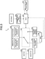
- FIG. 3 is a diagram illustrating an example of a configuration of the power source switching control system according to a second embodiment.
- a power source switching control system 2 includes the first power source 101, the second power source 102, the motor 103, the inverter 104, the onboard air conditioner 105, the BMU 106, the input/output appliance 107, the switch 109, an ECU 201, and a communication appliance 202.
- the communication appliance 202 acquires at least one of road congestion information and road environment information from an external device via a network such as the Internet.
- the road congestion information is information indicating a congestion state of a road to the destination, for example, a traveling route to the destination and the required time to the destination.
- the road environment information is information indicating the shape of the road to the destination, for example, a gradient of the road to the destination.
- the power source switching control system 2 attaching great importance to real-time performance of the acquired road congestion information and road environment information, acquires the road congestion information and the road environment information from the external device via the network using the communication appliance 202 included in the power source switching control system 2, but the embodiment is not limited thereto.
- the power source switching control system 2 may acquire the road congestion information and the road environment information from the external device via the network using a communication appliance included in on-vehicle equipment of the EV bus B or an external communication appliance.
- the ECU 201 predicts a charging time at the charger installation place based on at least one of the road congestion information and the road environment information acquired by the communication appliance 202. Consequently, prediction accuracy for the charging time at the charger installation place can be improved, so that the electricity storage amount of the first power source 101 can be prevented from running out in travel of the EV bus B to the destination.
- the arriving time at the charger installation place is estimated to be delayed, so that the ECU 201 predicts an estimated time to be shorter corresponding to a predetermined rate.
- the arriving time at the destination is estimated to be earlier, so that the ECU 201 predicts the estimated time to be longer corresponding to a predetermined rate.
- the ECU 201 also calculates the required electricity storage amount based on at least one of the road congestion information and the road environment information acquired by the communication appliance 202. Consequently, calculation accuracy for the required electricity storage amount can be improved, so that the electricity storage amount of the first power source 101 can be prevented from running out in travel of the EV bus B to the destination. For example, when the road congestion information indicates that the traveling route to the destination is jammed up, or a case in which the road environment information indicates that there are many curves in the traveling route to the destination or a gradient of an upward slope to the destination is equal to or larger than a predetermined angle, the required time to the destination is prolonged with high possibility, so that the ECU 201 calculates the required electricity storage amount to be larger corresponding to a predetermined rate.
- the required time to the destination is shortened with high possibility, so that the ECU 201 calculates the required electricity storage amount to be smaller corresponding to a predetermined rate.
- an error may be caused in the amount depending on the congestion state of the route indicated by the route information. For example, power consumption in the EV bus B increases when the road is congested and the traveling time to the destination is prolonged, and a larger electricity storage amount than the required electricity storage amount may be consumed by the motor 103. If the required electricity storage amount is calculated simply with the route on which the EV bus B travels to the destination, an error may be caused in the amount depending on the shape of the route.
- the charging time and the required electricity storage amount are calculated based on at least one of the road congestion information and the road environment information acquired by the communication appliance 202, so that calculation accuracy for the required electricity storage amount can be improved.
- the power source switching control system 2 can prevent the electricity storage amount of the first power source 101 from running out in travel of the EV bus B to the destination.
- the present embodiment is an example of predicting the charging time and calculating the required electricity storage amount by an onboard PC of the EV bus.
- the same component as that in the first and the second embodiments is omitted.
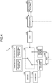
- FIG. 4 is a diagram illustrating an example of a configuration of the power source switching control system according to a third embodiment.
- a power source switching control system 3 includes the first power source 101, the second power source 102, the motor 103, the inverter 104, the onboard air conditioner 105, the BMU 106, an input/output appliance 301, the switch 109, an ECU 302, and an onboard PC 303.
- the input/output appliance 301 inputs various pieces of information such as the destination information, the present location information, the charger installation place, the type information, the schedule, the route information, and the like to the onboard PC 303 described later.
- the onboard PC 303 is mounted on the EV bus B, and functions as a prediction unit that predicts the charging time and a calculator that calculates the required electricity storage amount. The onboard PC 303 then notifies the ECU 302 of the calculated required electricity storage amount.
- the ECU 302 controls the switch 109 to switch the power source of the onboard air conditioner 105 to the second power source 102. Consequently, even if software functioning as the prediction unit that predicts the charging time and the calculator that calculates the required electricity storage amount is not installed in the ECU 302 in advance, the switch 109 can be controlled by using the required electricity storage amount calculated by the onboard PC 303, so that a function of controlling the switch 109 using the required electricity storage amount can be added later.
- the switch 109 for switching the power source of the onboard air conditioner 105 to the first power source 101 or the second power source 102 needs to be added to the EV bus B in advance.
- the ECU 302 and the onboard PC 303 function as an example of the switching control device that controls switching of the power source of the onboard air conditioner 105.
- the present embodiment is an example of predicting the charging time at the charger installation place based on at least one of the congestion state of the road to the destination and the shape of the road to the destination, and calculating the required electricity storage amount based on at least one of the congestion state of the road to the destination and the shape of the road to the destination by the onboard PC 303.
- the same component as that in the second and the third embodiments is omitted.
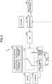
- FIG. 5 is a diagram illustrating an example of a configuration of the power source switching control system according to a fourth embodiment.
- a power source switching control system 4 includes the first power source 101, the second power source 102, the motor 103, the inverter 104, the onboard air conditioner 105, the BMU 106, the input/output appliance 301, the switch 109, the ECU 302, and an onboard PC 401.
- the onboard PC 401 acquires at least one of the road congestion information and the road environment information from an external device via a network such as the Internet.
- the onboard PC 401 predicts the charging time at the charger installation place based on at least one of the acquired road congestion information and road environment information.
- the onboard PC 401 also calculates the required electricity storage amount based on at least one of the acquired road congestion information and road environment information.
- the same working effect as that of the second embodiment can be obtained even when the prediction unit that predicts the charging time and the calculator that calculates the required electricity storage amount are implemented by the onboard PC 401.
- the present embodiment is an example of predicting the charging time and calculating the required electricity storage amount by a communication appliance.
- the same component as that in the first and the second embodiment is omitted.
- FIG. 6 is a diagram illustrating an example of a configuration of the power source switching control system according to a fifth embodiment.
- a power source switching control system 5 includes the first power source 101, the second power source 102, the motor 103, the inverter 104, the onboard air conditioner 105, the BMU 106, an input/output appliance 501, the switch 109, an ECU 502, and a communication appliance 503.
- the input/output appliance 501 inputs various pieces of information such as the destination information, the present location information, the charger installation place, the type information, the schedule, and the route information to the communication appliance 503 described later.
- the communication appliance 503 functions as a prediction unit that predicts the charging time and a calculator that calculates the required electricity storage amount. The communication appliance 503 then notifies the ECU 502 of the calculated required electricity storage amount.
- the ECU 502 controls the switch 109 to switch the power source of the onboard air conditioner 105 to the second power source 102. Consequently, even if software functioning as the prediction unit that predicts the charging time and the calculator that calculates the required electricity storage amount is not installed in the ECU 502 in advance, the switch 109 can be controlled by using the required electricity storage amount calculated by the communication appliance 503, so that a function of controlling the switch 109 using the required electricity storage amount can be added later. However, the switch 109 for switching the power source of the onboard air conditioner 105 to the first power source 101 or the second power source 102 needs to be added to the EV bus B in advance. Accordingly, in the present embodiment, the ECU 502 and the communication appliance 503 function as an example of the switching control device that controls switching of the power source of the onboard air conditioner 105.
- the present embodiment is an example of predicting the charging time and calculating the required electricity storage amount on an external server.
- the same component as that in the first and the second embodiments is omitted.
- FIG. 7 is a diagram illustrating an example of a configuration of the power source switching control system according to a sixth embodiment.
- a power source switching control system 6 includes the first power source 101, the second power source 102, the motor 103, the inverter 104, the onboard air conditioner 105, the BMU 106, the input/output appliance 501, the switch 109, an ECU 601, and a communication appliance 602.
- the communication appliance 602 transmits, to a cloud server 603, various pieces of information such as the destination information, the present location information, the charger installation place, the type information, the schedule, and the route information input from the input/output appliance 501.
- the cloud server 603 (an example of an external server) functions as a prediction unit that predicts the charging time and a calculator that calculates the required electricity storage amount using the various pieces of information input from the communication appliance 602.
- the cloud server 603 notifies the ECU 601 of the calculated required electricity storage amount via the communication appliance 602.
- the cloud server 603 may correct the calculated required electricity storage amount based on a calculation history of the required electricity storage amount. Consequently, calculation accuracy for the required electricity storage amount can be improved.
- one appliance can calculate the required electricity storage amount of the first poser source 101 of a plurality of EV buses B at the same time.
- the ECU 601 receives the required electricity storage amount from the cloud server 603 via the communication appliance 602.
- the ECU 601 controls the switch 109 to switch the power source of the onboard air conditioner 105 to the second power source 102. Consequently, even if software functioning as the prediction unit that predicts the charging time and the calculator that calculates the required electricity storage amount is not installed in the ECU 601 in advance, the switch 109 can be controlled by using the required electricity storage amount calculated by the cloud server 603, so that a function of controlling the switch 109 using the required electricity storage amount can be added later. However, the switch 109 for switching the power source of the onboard air conditioner 105 to the first power source 101 or the second power source 102 needs to be added to the EV bus B in advance.
- a long-distance traveling plan for the EV bus B using the electricity storage functional unit as a power source can be made.
Landscapes
- Engineering & Computer Science (AREA)
- Power Engineering (AREA)
- Mechanical Engineering (AREA)
- Transportation (AREA)
- Combustion & Propulsion (AREA)
- Chemical & Material Sciences (AREA)
- Life Sciences & Earth Sciences (AREA)
- Sustainable Development (AREA)
- Sustainable Energy (AREA)
- Physics & Mathematics (AREA)
- Emergency Management (AREA)
- Business, Economics & Management (AREA)
- Automation & Control Theory (AREA)
- Theoretical Computer Science (AREA)
- Thermal Sciences (AREA)
- Software Systems (AREA)
- Mathematical Physics (AREA)
- Fuzzy Systems (AREA)
- Charge And Discharge Circuits For Batteries Or The Like (AREA)
- Electric Propulsion And Braking For Vehicles (AREA)
- Hybrid Electric Vehicles (AREA)
- Stand-By Power Supply Arrangements (AREA)
- Air-Conditioning For Vehicles (AREA)
Abstract
Description
- Embodiments of the present invention relate to a switching control device and a switching control method.
- A traveling distance of an electric vehicle not including an internal combustion engine is limited by an electricity storage amount of an electricity storage functional unit such as a storage battery, and the traveling distance thereof is shorter than that of an automobile including an internal combustion engine. Due to this, for a hybrid car including a plurality of power sources such as an electricity storage functional unit and an internal combustion engine, a method of increasing traveling distance by switching between a power source for air conditioning and a power source for traveling has been examined.
- For example, for hybrid cars, there is a method of causing an electricity storage functional unit to function as a power source for air conditioning and traveling until a distance to a destination becomes equal to or smaller than a predetermined distance, and causing an internal combustion engine to function as the power source for air conditioning and traveling when the distance to the destination becomes equal to or smaller than the predetermined distance. For hybrid cars, there is a method in which, assuming that an electricity storage amount of the electricity storage functional unit when the hybrid car arrives at the destination is a target amount, when the electricity storage amount of the electricity storage functional unit becomes equal to or smaller than the target amount before the hybrid car arrives at the destination, the internal combustion engine is made to be the power source for air conditioning and traveling.
- Patent Literature 1: Japanese Patent Application Laid-open No.
2008-150035 - However, with a conventional method of switching a power source, an internal combustion engine is switched to a power source for air conditioning and traveling when a distance to a destination becomes equal to or smaller than a predetermined distance or when an electricity storage amount of an electricity storage functional unit becomes equal to or smaller than a target amount, so that it is difficult to make a long-distance traveling plan using the electricity storage functional unit as a power source.
- A switching control device according to an embodiment includes a controller, a prediction unit, and a calculator. The controller controls a switching unit that is able to switch a power source of an air conditioning appliance of an electric bus operating according to a predetermined schedule to a first electricity storage functional unit or a predetermined power source. The first electricity storage functional unit is a power source of a motor that causes the electric bus to travel. The predetermined power source is different from the first electricity storage functional unit. The prediction unit predicts a charging time during which the first electricity storage functional unit is able to be charged by a charger at a first position at which the first electricity storage functional unit is able to be charged. The calculator calculates, based on the schedule, a first electricity storage amount of the first electricity storage functional unit required for driving the motor to a second position excepting a charging amount charged to the first electricity storage functional unit at the first position corresponding to the charging time based on the schedule. When the electricity storage amount of the first electricity storage functional unit is equal to or smaller than the first electricity storage amount, the controller controls the switching unit to switch the power source of the air conditioning appliance to a predetermined power source from the first electricity storage functional unit.
-
-
FIG. 1 is a diagram illustrating an example of a configuration of a power source switching control system according to a first embodiment. -
FIG. 2 is a flowchart illustrating an example of a procedure of switching of a power source of an onboard air conditioner in the power source switching control system according to the first embodiment. -
FIG. 3 is a diagram illustrating an example of a configuration of a power source switching control system according to a second embodiment. -
FIG. 4 is a diagram illustrating an example of a configuration of a power source switching control system according to a third embodiment. -
FIG. 5 is a diagram illustrating an example of a configuration of a power source switching control system according to a fourth embodiment. -
FIG. 6 is a diagram illustrating an example of a configuration of a power source switching control system according to a fifth embodiment. -
FIG. 7 is a diagram illustrating an example of a configuration of a power source switching control system according to a sixth embodiment. - The following describes, with reference to the attached drawings, an air conditioning power source switching system to which a switching control device and a switching control method according to embodiments is applied.
-
FIG. 1 is a diagram illustrating an example of a configuration of a power source switching control system according to a first embodiment. As illustrated inFIG. 1 , a power source switching control system 1 according to the present embodiment is applied to an electric vehicle (EV) bus B (an example of an electric bus) operating according to a predetermined schedule using an electricity storage functional unit such as a storage battery as a power source. Specifically, as illustrated inFIG. 1 , the power source switching control system 1 includes afirst power source 101, asecond power source 102, amotor 103, aninverter 104, an onboard air conditioner 105 (hereinafter, referred to as an onboard air conditioner), a battery management unit (BMU) 106, an input/output appliance 107, an engine control unit (ECU) 108, and aswitch 109. - The first power source 101 (an example of a first electricity storage functional unit) is an electricity storage functional unit such as a storage battery serving as a power source of at least the
motor 103 and theonboard air conditioner 105 among loads included in the EV bus B. In the present embodiment, thefirst power source 101 is a power source of auxiliary machinery included in the EV bus B in addition to themotor 103 and theonboard air conditioner 105. The second power source 102 (an example of a predetermined power source) can function as a power source of theonboard air conditioner 105. In the present embodiment, thesecond power source 102 is not used as a power source of the loads other than theonboard air conditioner 105. In the present embodiment, an electricity storage functional unit such as a storage battery is used as thesecond power source 102, but it is sufficient that thesecond power source 102 can be used as the power source of theonboard air conditioner 105. For example, thesecond power source 102 may be a hydrogen fuel engine, a diesel engine, a gasoline engine, a power generator, and the like. - The
motor 103 is an electric motor that causes the EV bus B equipped with the power source switching control system 1 to travel. Theinverter 104 changes a current flowing from thefirst power source 101 to themotor 103 and a voltage applied to themotor 103 from thefirst power source 101 corresponding to a rating of themotor 103. Theonboard air conditioner 105 is an example of an air conditioning appliance that adjusts temperature and the like in the EV bus B. In the present embodiment, theonboard air conditioner 105 includes an air-cooling system that lowers the temperature in the EV bus B, and an air-heating system that raises the temperature in the EV bus B. The BMU 106 controls charging and discharging of thefirst power source 101 and thesecond power source 102, and detects the temperature and a residual capacity (state of charge: SOC) of thefirst power source 101 and thesecond power source 102, for example. - Through the input/
output appliance 107, it is possible to input various pieces of information such as destination information indicating a destination of the EV bus B, present location information indicating a position (a present location) of the EV bus B, a position at which a charger is provided that can charge the first power source 101 (a charger installation place), type information (for example, a quick charger) related to the charger provided at the charger installation place, a schedule indicating scheduled arrival time and the like at which the EV bus B is scheduled to arrive at a destination, and route information indicating a route of the EV bus B to the destination. - The
switch 109 is a switching unit that is able to switch the power source of theonboard air conditioner 105 to thefirst power source 101 or thesecond power source 102. The ECU 108 (an example of a controller) performs electric control in the EV bus B such as switching of a power source of each load unit included in the EV bus B or control of theBMU 106. In the present embodiment, theECU 108 includes a central processing unit (CPU), a read only memory (ROM), a random access memory (RAM), and the like. The CPU then executes various programs such as power source switching control software stored in the ROM using the RAM as a working area to perform electric control in the EV bus B. In this case, the power source switching control software is a program for switching the power source of theonboard air conditioner 105 to thefirst power source 101 or thesecond power source 102. - Next, with reference to
FIG. 1 , the following describes switching for the power source of theonboard air conditioner 105 in the power source switching control system 1 according to the present embodiment. - When the EV bus B equipped with the power source switching control system 1 starts to travel, the ECU 108 controls the BMU 106 to supply electric power to the
motor 103 from thefirst power source 101. The ECU 108 also controls theswitch 109 to switch the power source of theonboard air conditioner 105 to thefirst power source 101, and causes theonboard air conditioner 105 to operate. Next, based on the destination information, the present location information, the charger installation place, the type information, the schedule, the route information, and the like input from the input/output appliance 107, theECU 108 calculates an electricity storage amount of thefirst power source 101 required for driving themotor 103 in travel of the EV bus B to the destination (hereinafter, referred to as a required electricity storage amount). - When the EV bus B stops at the charger installation place before arriving at the destination, the
first power source 101 of the EV bus B is able to be charged before arriving at the destination, so that a possible traveling distance can be prolonged by electric power supplied from the chargedfirst power source 101. However, when the EV bus B stops at the destination before arriving at the charger installation place, the EV bus B needs to secure at least an electricity storage amount required for traveling to the destination for thefirst power source 101. When the scheduled arrival time at the destination is set in the schedule, a time during which the EV bus B can stop at the charger installation place is predetermined, so that thefirst power source 101 cannot be charged with electricity the storage amount of which is required for traveling to the destination in some cases at the charger installation place. Additionally, depending on specs of thefirst power source 101 included in the EV bus B or a battery capacity, thefirst power source 101 cannot be charged with electricity the storage amount of which is required for traveling to the destination in some cases. - Thus, the
ECU 108 needs to calculate required amount of electric power in consideration of variable factors such as the scheduled arrival time at the destination of the EV bus B, the specs of thefirst power source 101, and the battery capacity of thefirst power source 101. Specifically, the ECU 108 (an example of a prediction unit) predicts a charging time during which thefirst power source 101 is able to be charged by the charger installed at the charger installation place, at the charger installation place at which thefirst power source 101 is able to be charged (an example of a first position). Next, the ECU 108 (an example of a calculator) calculates, as the required electricity storage amount (an example of a first electricity storage amount), the electricity storage amount of thefirst power source 101 required for driving themotor 103 in travel of the EV bus B to the destination (an example of a second position) excepting the storage amount of electricity charged to thefirst power source 101 at the charger installation place according to the predicted charging time based on the schedule. In the present embodiment, the required electricity storage amount is calculated based on the traveling distance of the EV bus B per predetermined electricity storage amount and the distance to the destination. - Specifically, when the EV bus B arrives at the destination before arriving at the charger installation place, or a case in which the destination of the EV bus B is the charger setting place, the
ECU 108 calculates, as the required electricity storage amount, the electricity storage amount of thefirst power source 101 required for driving themotor 103 in travel of the EV bus B to the destination. More specifically, theECU 108 calculates, as the required electricity storage amount, a value obtained by multiplying the predetermined electricity storage amount by a value obtained by dividing the distance from the present location to the destination by the traveling distance per predetermined electricity storage amount. - By contrast, when the EV bus B arrives at the charger installation place before arriving at the destination, the
ECU 108 calculates, as the required electricity storage amount, an electricity storage amount obtained by subtracting the storage amount of electricity charged to thefirst power source 101 at the charger installation place corresponding to the predicted charging time from the electricity storage amount of thefirst power source 101 required for driving themotor 103 in travel of the EV bus B to the destination. More specifically, the ECU 108 calculates a remaining distance by subtracting the possible traveling distance of the EV bus B with the storage amount of electricity charged to thefirst power source 101 at the charger installation place from the distance from the present location to the destination. TheECU 108 then calculates, as the required electricity storage amount, a value obtained by multiplying the predetermined electricity storage amount by a value obtained by dividing the calculated remaining distance by the traveling distance per predetermined electricity storage amount. However, when the calculated required electricity storage amount is smaller than the electricity storage amount of thefirst power source 101 required for driving themotor 103 to the charger installation place at which the EV bus B stops before arriving at the destination, theECU 108 corrects the calculated required electricity storage amount at least to the electricity storage amount of thefirst power source 101 required for driving themotor 103 to the charger installation place. - When the electricity storage amount of the
first power source 101 becomes equal to or smaller than the required electricity storage amount, theECU 108 controls theswitch 109 to switch the power source of theonboard air conditioner 105 to thesecond power source 102. Consequently, the EV bus B can be caused to travel to the destination using the electricity storage functional unit constituting thefirst power source 101 as a power source for themotor 103, so that a long-distance traveling plan using the electricity storage functional unit as a power source can be made. Accordingly, in the present embodiment, theECU 108 functions as an example of a switching control device that controls switching of the power source of theonboard air conditioner 105. - Next, with reference to
FIG. 2 , the following describes an example of a procedure of switching of the power source of theonboard air conditioner 105 in the power source switching control system 1 according to the present embodiment.FIG. 2 is a flowchart illustrating an example of a procedure of switching of the power source of the onboard air conditioner in the power source switching control system according to the first embodiment. - When the EV bus B starts to travel, the
ECU 108 determines whether the route information is input from the input/output appliance 107 (Step S110). If the route information is not input from the input/output appliance 107 (No at Step S110), theECU 108 calculates the route information using the destination information, the present location information, the charger installation place, the type information, the schedule, and the like (Step Sill). If the route information is input from the input/output appliance 107 (Yes at Step S110) or the route information is calculated, theECU 108 specifies charger installation places on the route of the EV bus B indicated by the route information. TheECU 108 then determines whether there is a charger installation place at which the EV bus B stops before arriving at the destination indicated by the destination information in the specified charger installation places (Step S112). If there is no charger setting place at which the EV bus B stops before arriving at the destination (No at Step S112), theECU 108 calculates, as the required electricity storage amount, the electricity storage amount of thefirst power source 101 required for driving themotor 103 in travel of the EV bus B to the destination (Step S113). - Thereafter, until the EV bus B arrives at the destination, the
ECU 108 determines whether the electricity storage amount of thefirst power source 101 is equal to or smaller than the calculated required electricity storage amount every predetermined period (Step S114). If the electricity storage amount of thefirst power source 101 is not equal to or smaller than the calculated required electricity storage amount (No at Step S114), theECU 108 leaves thefirst power source 101 as the power source of the onboard air conditioner 105 (Step S115). By contrast, if the electricity storage amount of thefirst power source 101 is equal to or smaller than the calculated required electricity storage amount (Yes at Step S114), theECU 108 controls theswitch 109 to switch the power source of theonboard air conditioner 105 to the second power source 102 (Step S116). - At Step S112, if there is a charger setting place at which the EV bus B stops before arriving at the destination (Yes at Step S112), the
ECU 108 specifies scheduled arrival time (an example of arrival time) of the EV bus B at the destination according to the schedule and the like input from the input/output appliance 107 (Step S117). Next, based on the scheduled arrival time of the EV bus B at the destination, theECU 108 predicts the charging time during which thefirst power source 101 is able to be charged at the charger installation place at which the EV bus B stops before arriving at the destination. At the charger installation place at which the EV bus B stops before arriving at the destination, theECU 108 calculates the storage amount of electricity that is able to be charged to thefirst power source 101 in the predicted charging time (hereinafter, referred to as a charging electricity storage amount) (Step S118). - The
ECU 108 also calculates the electricity storage amount of thefirst power source 101 required for driving themotor 103 in travel of the EV bus B from the present location to the destination (hereinafter, referred to as a total electricity storage amount). TheECU 108 then calculates, as the required electricity storage amount, the electricity storage amount obtained by subtracting the charging electricity storage amount from the total electricity storage amount (Step S119). Thereafter, until the EV bus B arrives at the destination, theECU 108 determines whether the electricity storage amount of thefirst power source 101 is equal to or smaller than the calculated required electricity storage amount every predetermined period (Step S120). If the electricity storage amount of thefirst power source 101 is not equal to or smaller than the calculated required electricity storage amount (No at Step S120), theECU 108 leaves thefirst power source 101 as the power source of the onboard air conditioner 105 (Step S121). By contrast, if the electricity storage amount of thefirst power source 101 is equal to or smaller than the calculated required electricity storage amount (Yes at Step S120), theECU 108 controls theswitch 109 to switch the power source of theonboard air conditioner 105 to the second power source 102 (Step S122). - In this way, with the power source switching control system 1 according to the first embodiment, a long-distance traveling plan for the EV bus B using the electricity storage functional unit as a power source can be made.
- The present embodiment is an example of predicting the charging time at the charger installation place based on at least one of a congestion state of a road to the destination and a shape of the road to the destination, and calculating the required electricity storage amount based on at least one of the congestion state of the road to the destination and the shape of the road to the destination. In the following description, the same component as that in the first embodiment is omitted.
-
FIG. 3 is a diagram illustrating an example of a configuration of the power source switching control system according to a second embodiment. As illustrated inFIG. 3 , a power source switchingcontrol system 2 according to the present embodiment includes thefirst power source 101, thesecond power source 102, themotor 103, theinverter 104, theonboard air conditioner 105, theBMU 106, the input/output appliance 107, theswitch 109, anECU 201, and acommunication appliance 202. Thecommunication appliance 202 acquires at least one of road congestion information and road environment information from an external device via a network such as the Internet. In this case, the road congestion information is information indicating a congestion state of a road to the destination, for example, a traveling route to the destination and the required time to the destination. The road environment information is information indicating the shape of the road to the destination, for example, a gradient of the road to the destination. In the present embodiment, attaching great importance to real-time performance of the acquired road congestion information and road environment information, the power source switchingcontrol system 2 acquires the road congestion information and the road environment information from the external device via the network using thecommunication appliance 202 included in the power source switchingcontrol system 2, but the embodiment is not limited thereto. For example, the power source switchingcontrol system 2 may acquire the road congestion information and the road environment information from the external device via the network using a communication appliance included in on-vehicle equipment of the EV bus B or an external communication appliance. - In the present embodiment, the
ECU 201 predicts a charging time at the charger installation place based on at least one of the road congestion information and the road environment information acquired by thecommunication appliance 202. Consequently, prediction accuracy for the charging time at the charger installation place can be improved, so that the electricity storage amount of thefirst power source 101 can be prevented from running out in travel of the EV bus B to the destination. For example, when the road congestion information indicates that the traveling route to the destination is jammed up, or a case in which the road environment information indicates that there are many curves in the traveling route to the destination or a gradient of an upward slope to the destination is equal to or larger than a predetermined angle, the arriving time at the charger installation place is estimated to be delayed, so that theECU 201 predicts an estimated time to be shorter corresponding to a predetermined rate. By contrast, when the road congestion information indicates that the traveling route to the destination is not jammed up, or a case in which the road environment information indicates that there are many straight lines in the traveling route to the destination or a gradient to the destination is smaller than the predetermined angle, the arriving time at the destination is estimated to be earlier, so that theECU 201 predicts the estimated time to be longer corresponding to a predetermined rate. - The
ECU 201 also calculates the required electricity storage amount based on at least one of the road congestion information and the road environment information acquired by thecommunication appliance 202. Consequently, calculation accuracy for the required electricity storage amount can be improved, so that the electricity storage amount of thefirst power source 101 can be prevented from running out in travel of the EV bus B to the destination. For example, when the road congestion information indicates that the traveling route to the destination is jammed up, or a case in which the road environment information indicates that there are many curves in the traveling route to the destination or a gradient of an upward slope to the destination is equal to or larger than a predetermined angle, the required time to the destination is prolonged with high possibility, so that theECU 201 calculates the required electricity storage amount to be larger corresponding to a predetermined rate. By contrast, when the road congestion information indicates that the traveling route to the destination is not jammed up, or a case in which the road environment information indicates that there are many straight lines in the traveling route to the destination or a gradient to the destination is smaller than the predetermined angle, the required time to the destination is shortened with high possibility, so that theECU 201 calculates the required electricity storage amount to be smaller corresponding to a predetermined rate. - As described above, if the required electricity storage amount is calculated simply with the route on which the EV bus B travels to the destination, an error may be caused in the amount depending on the congestion state of the route indicated by the route information. For example, power consumption in the EV bus B increases when the road is congested and the traveling time to the destination is prolonged, and a larger electricity storage amount than the required electricity storage amount may be consumed by the
motor 103. If the required electricity storage amount is calculated simply with the route on which the EV bus B travels to the destination, an error may be caused in the amount depending on the shape of the route. For example, higher torque is required for the EV bus B and power consumption increases as a gradient of an upward slope on the route increases, and a larger electricity storage amount than the required electricity storage amount may be consumed by themotor 103. However, according to the present embodiment, as described above, the charging time and the required electricity storage amount are calculated based on at least one of the road congestion information and the road environment information acquired by thecommunication appliance 202, so that calculation accuracy for the required electricity storage amount can be improved. - In this way, the power source switching
control system 2 according to the second embodiment can prevent the electricity storage amount of thefirst power source 101 from running out in travel of the EV bus B to the destination. - The present embodiment is an example of predicting the charging time and calculating the required electricity storage amount by an onboard PC of the EV bus. In the following description, the same component as that in the first and the second embodiments is omitted.
-
FIG. 4 is a diagram illustrating an example of a configuration of the power source switching control system according to a third embodiment. As illustrated inFIG. 4 , a power source switchingcontrol system 3 according to the present embodiment includes thefirst power source 101, thesecond power source 102, themotor 103, theinverter 104, theonboard air conditioner 105, theBMU 106, an input/output appliance 301, theswitch 109, anECU 302, and anonboard PC 303. In the present embodiment, the input/output appliance 301 inputs various pieces of information such as the destination information, the present location information, the charger installation place, the type information, the schedule, the route information, and the like to theonboard PC 303 described later. Theonboard PC 303 is mounted on the EV bus B, and functions as a prediction unit that predicts the charging time and a calculator that calculates the required electricity storage amount. Theonboard PC 303 then notifies theECU 302 of the calculated required electricity storage amount. - When the electricity storage amount of the
first power source 101 is equal to or smaller than the required electricity storage amount notified from theonboard PC 303, theECU 302 controls theswitch 109 to switch the power source of theonboard air conditioner 105 to thesecond power source 102. Consequently, even if software functioning as the prediction unit that predicts the charging time and the calculator that calculates the required electricity storage amount is not installed in theECU 302 in advance, theswitch 109 can be controlled by using the required electricity storage amount calculated by theonboard PC 303, so that a function of controlling theswitch 109 using the required electricity storage amount can be added later. However, theswitch 109 for switching the power source of theonboard air conditioner 105 to thefirst power source 101 or thesecond power source 102 needs to be added to the EV bus B in advance. Accordingly, in the present embodiment, theECU 302 and theonboard PC 303 function as an example of the switching control device that controls switching of the power source of theonboard air conditioner 105. - In this way, with the power source switching
control system 3 according to the third embodiment, the function of controlling theswitch 109 using the required electricity storage amount can be added later. - The present embodiment is an example of predicting the charging time at the charger installation place based on at least one of the congestion state of the road to the destination and the shape of the road to the destination, and calculating the required electricity storage amount based on at least one of the congestion state of the road to the destination and the shape of the road to the destination by the
onboard PC 303. In the following description, the same component as that in the second and the third embodiments is omitted. -
FIG. 5 is a diagram illustrating an example of a configuration of the power source switching control system according to a fourth embodiment. As illustrated inFIG. 5 , a power source switching control system 4 according to the present embodiment includes thefirst power source 101, thesecond power source 102, themotor 103, theinverter 104, theonboard air conditioner 105, theBMU 106, the input/output appliance 301, theswitch 109, theECU 302, and anonboard PC 401. In the present embodiment, theonboard PC 401 acquires at least one of the road congestion information and the road environment information from an external device via a network such as the Internet. Theonboard PC 401 then predicts the charging time at the charger installation place based on at least one of the acquired road congestion information and road environment information. Theonboard PC 401 also calculates the required electricity storage amount based on at least one of the acquired road congestion information and road environment information. - In this way, with the power source switching control system 4 according to the fourth embodiment, the same working effect as that of the second embodiment can be obtained even when the prediction unit that predicts the charging time and the calculator that calculates the required electricity storage amount are implemented by the
onboard PC 401. - The present embodiment is an example of predicting the charging time and calculating the required electricity storage amount by a communication appliance. In the following description, the same component as that in the first and the second embodiment is omitted.
-
FIG. 6 is a diagram illustrating an example of a configuration of the power source switching control system according to a fifth embodiment. As illustrated inFIG. 6 , a power source switchingcontrol system 5 according to the present embodiment includes thefirst power source 101, thesecond power source 102, themotor 103, theinverter 104, theonboard air conditioner 105, theBMU 106, an input/output appliance 501, theswitch 109, anECU 502, and acommunication appliance 503. In the present embodiment, the input/output appliance 501 inputs various pieces of information such as the destination information, the present location information, the charger installation place, the type information, the schedule, and the route information to thecommunication appliance 503 described later. Thecommunication appliance 503 functions as a prediction unit that predicts the charging time and a calculator that calculates the required electricity storage amount. Thecommunication appliance 503 then notifies theECU 502 of the calculated required electricity storage amount. - When the electricity storage amount of the
first power source 101 is equal to or smaller than the required electricity storage amount notified from thecommunication appliance 503, theECU 502 controls theswitch 109 to switch the power source of theonboard air conditioner 105 to thesecond power source 102. Consequently, even if software functioning as the prediction unit that predicts the charging time and the calculator that calculates the required electricity storage amount is not installed in theECU 502 in advance, theswitch 109 can be controlled by using the required electricity storage amount calculated by thecommunication appliance 503, so that a function of controlling theswitch 109 using the required electricity storage amount can be added later. However, theswitch 109 for switching the power source of theonboard air conditioner 105 to thefirst power source 101 or thesecond power source 102 needs to be added to the EV bus B in advance. Accordingly, in the present embodiment, theECU 502 and thecommunication appliance 503 function as an example of the switching control device that controls switching of the power source of theonboard air conditioner 105. - In this way, with the power source switching
control system 5 according to the fifth embodiment, the function of controlling theswitch 109 using the required electricity storage amount can be added later. - The present embodiment is an example of predicting the charging time and calculating the required electricity storage amount on an external server. In the following description, the same component as that in the first and the second embodiments is omitted.
-
FIG. 7 is a diagram illustrating an example of a configuration of the power source switching control system according to a sixth embodiment. As illustrated inFIG. 7 , a power source switchingcontrol system 6 according to the present embodiment includes thefirst power source 101, thesecond power source 102, themotor 103, theinverter 104, theonboard air conditioner 105, theBMU 106, the input/output appliance 501, theswitch 109, anECU 601, and acommunication appliance 602. In the present embodiment, thecommunication appliance 602 transmits, to acloud server 603, various pieces of information such as the destination information, the present location information, the charger installation place, the type information, the schedule, and the route information input from the input/output appliance 501. The cloud server 603 (an example of an external server) functions as a prediction unit that predicts the charging time and a calculator that calculates the required electricity storage amount using the various pieces of information input from thecommunication appliance 602. Thecloud server 603 notifies theECU 601 of the calculated required electricity storage amount via thecommunication appliance 602. Thecloud server 603 may correct the calculated required electricity storage amount based on a calculation history of the required electricity storage amount. Consequently, calculation accuracy for the required electricity storage amount can be improved. In a case of calculating the required electricity storage amount by thecloud server 603, one appliance can calculate the required electricity storage amount of thefirst poser source 101 of a plurality of EV buses B at the same time. - The
ECU 601 receives the required electricity storage amount from thecloud server 603 via thecommunication appliance 602. When the electricity storage amount of thefirst power source 101 is equal to or smaller than the required electricity storage amount received from thecloud server 603, theECU 601 controls theswitch 109 to switch the power source of theonboard air conditioner 105 to thesecond power source 102. Consequently, even if software functioning as the prediction unit that predicts the charging time and the calculator that calculates the required electricity storage amount is not installed in theECU 601 in advance, theswitch 109 can be controlled by using the required electricity storage amount calculated by thecloud server 603, so that a function of controlling theswitch 109 using the required electricity storage amount can be added later. However, theswitch 109 for switching the power source of theonboard air conditioner 105 to thefirst power source 101 or thesecond power source 102 needs to be added to the EV bus B in advance. - In this way, with the power source switching
control system 6 according to the sixth embodiment, a function of controlling theswitch 109 using the required electricity storage amount can be added later. - As described above, according to the first to the sixth embodiments, a long-distance traveling plan for the EV bus B using the electricity storage functional unit as a power source can be made.
- Some embodiments of the present invention have been described above. The embodiments are exemplary only, and do not intend to limit the scope of the invention. These novel embodiments can be implemented in other various forms, and can be variously omitted, replaced, and modified without departing from the gist of the invention. These embodiments and modifications thereof are encompassed by the scope and the gist of the invention, and also encompassed by the invention described in claims and equivalents thereof.
Claims (9)
- A switching control device comprising:a controller configured to control a switching unit that is able to switch a power source of an air conditioning appliance of an electric bus operating according to a predetermined schedule to a first electricity storage functional unit or a predetermined power source, the first electricity storage functional unit being a power source of a motor that causes the electric bus to travel, and the predetermined power source being different from the first electricity storage functional unit;a prediction unit configured to predict a charging time during which the first electricity storage functional unit is able to be charged by a charger at a first position at which the first electricity storage functional unit is able to be charged; anda calculator configured to calculate, based on the schedule, a first electricity storage amount of the first electricity storage functional unit required for driving the motor to a second position excepting a charging amount charged to the first electricity storage functional unit at the first position corresponding to the charging time based on the schedule, wherein,when an electricity storage amount of the first electricity storage functional unit is equal to or smaller than the first electricity storage amount, the controller controls the switching unit to switch the power source of the air conditioning appliance to the predetermined power source from the first electricity storage functional unit.
- The switching control device according to claim 1, wherein the calculator calculates, as the first electricity storage amount, an electricity storage amount larger than the electricity storage amount required for driving the motor to one of the first position and the second position, at which the electric bus stops earlier.
- The switching control device according to claim 1, wherein the prediction unit predicts the charging time based on arrival time of the electric bus at the first position according to the schedule.
- The switching control device according to claim 1, wherein the calculator calculates the first electricity storage amount based on a traveling distance of the electric bus per predetermined electricity storage amount and a distance to the first position.
- The switching control device according to claim 1, wherein
the prediction unit predicts the charging time based on at least one of a congestion state of a road to the second position and a shape of the road to the second position, and
the calculator calculates the first electricity storage amount based on at least one of the congestion state of the road to the second position and the shape of the road to the second position. - The switching control device according to claim 1, wherein the predetermined power source is a second electricity storage functional unit different from the first electricity storage functional unit, or a power generator.
- The switching control device according to claim 1, wherein the prediction unit and the calculator are arranged in an onboard PC arranged in the electric bus.
- The switching control device according to claim 1, wherein the controller receives the first electricity storage amount from an external server in which the prediction unit and the calculator are arranged, and when the electricity storage amount of the first electricity storage functional unit is equal to or smaller than the received first electricity storage amount, the controller controls the switching unit to switch the power source of the air conditioning appliance to the predetermined power source from the first electricity storage functional unit.
- A switching control method comprising:predicting a charging time during which a first electricity storage functional unit is able to be charged by a charger at a first position at which the first electricity storage functional unit is able to be charged, the first electricity storage functional unit being an electricity storage functional unit serving as a power source of a motor that causes an electric bus to operate according to a predetermined schedule to travel;calculating, based on the schedule, a first electricity storage amount of the first electricity storage functional unit required for driving the motor to a second position excepting a charging amount charged to the first electricity storage functional unit at the first position corresponding to the charging time; andwhen an electricity storage amount of the first electricity storage functional unit is equal to or smaller than the first electricity storage amount, controlling a switching unit to switch, from the first electricity storage functional unit, a power source of an air conditioning appliance of the electric bus, a power source of an air conditioning appliance of the electric bus, to a predetermined power source different from the first electricity storage functional unit.
Applications Claiming Priority (2)
| Application Number | Priority Date | Filing Date | Title |
|---|---|---|---|
| JP2016072292A JP6758879B2 (en) | 2016-03-31 | 2016-03-31 | Switching control device and switching control method |
| PCT/JP2016/087669 WO2017168875A1 (en) | 2016-03-31 | 2016-12-16 | Switching control device and switching control method |
Publications (3)
| Publication Number | Publication Date |
|---|---|
| EP3437914A1 true EP3437914A1 (en) | 2019-02-06 |
| EP3437914A4 EP3437914A4 (en) | 2019-11-27 |
| EP3437914B1 EP3437914B1 (en) | 2021-11-24 |
Family
ID=59963928
Family Applications (1)
| Application Number | Title | Priority Date | Filing Date |
|---|---|---|---|
| EP16897091.1A Active EP3437914B1 (en) | 2016-03-31 | 2016-12-16 | Switching control device and switching control method |
Country Status (6)
| Country | Link |
|---|---|
| US (1) | US20200039355A1 (en) |
| EP (1) | EP3437914B1 (en) |
| JP (1) | JP6758879B2 (en) |
| CN (1) | CN109070751B (en) |
| SG (1) | SG11201808512UA (en) |
| WO (1) | WO2017168875A1 (en) |
Families Citing this family (3)
| Publication number | Priority date | Publication date | Assignee | Title |
|---|---|---|---|---|
| DE102019118415A1 (en) * | 2019-07-08 | 2021-01-14 | Volkswagen Aktiengesellschaft | Charge duration prediction of a HV battery and motor vehicle |
| CN113022378B (en) * | 2021-03-01 | 2023-03-07 | 中国第一汽车股份有限公司 | Temperature consistency prediction method, temperature consistency prediction device, prediction equipment and storage medium |
| US20230112801A1 (en) * | 2021-10-13 | 2023-04-13 | Ford Global Technologies, Llc | Systems and methods for predicting charging events and preparing electrified vehicles for charging |
Family Cites Families (14)
| Publication number | Priority date | Publication date | Assignee | Title |
|---|---|---|---|---|
| JP3711445B2 (en) * | 2001-02-21 | 2005-11-02 | 株式会社デンソー | Vehicle air conditioning charge control device and in-vehicle battery charge management device |
| PE20110476A1 (en) * | 2008-07-01 | 2011-07-15 | Proterra Inc | CHARGING STATIONS FOR ELECTRIC VEHICLES |
| JP2012128633A (en) * | 2010-12-15 | 2012-07-05 | Aisin Seiki Co Ltd | Electric vehicle charging reservation method and charging reservation device |
| JP2012147580A (en) * | 2011-01-12 | 2012-08-02 | Toyota Motor Corp | Vehicle information management system, vehicle-mounted information terminal and vehicle information providing device |
| JP5712780B2 (en) * | 2011-05-12 | 2015-05-07 | 株式会社デンソー | Air conditioning control equipment for electric vehicles |
| WO2012176284A1 (en) * | 2011-06-21 | 2012-12-27 | トヨタ自動車 株式会社 | Vehicle control apparatus |
| EP2578997B1 (en) * | 2011-10-07 | 2020-01-08 | Hitachi, Ltd. | System for supporting a user of an electrically driven vehicle |
| JP2013225968A (en) * | 2012-04-20 | 2013-10-31 | Denso Corp | Power control unit for vehicle |
| JP2013255365A (en) * | 2012-06-07 | 2013-12-19 | Suzuki Motor Corp | Vehicle control device |
| TWI479772B (en) * | 2013-02-21 | 2015-04-01 | 台達電子工業股份有限公司 | Charging system for electric vehicle and charging method thereof |
| JP6199753B2 (en) * | 2014-01-24 | 2017-09-20 | 株式会社東芝 | Operation plan creation support device |
| JP6086092B2 (en) * | 2014-04-21 | 2017-03-01 | トヨタ自動車株式会社 | Hybrid vehicle |
| US9702718B2 (en) * | 2015-05-08 | 2017-07-11 | Toyota Motor Engineering & Manufacturing North America, Inc. | Systems and methods for improving energy efficiency of a vehicle based on route prediction |
| JP6399026B2 (en) * | 2016-03-30 | 2018-10-03 | トヨタ自動車株式会社 | Hybrid vehicle and linkage system |
-
2016
- 2016-03-31 JP JP2016072292A patent/JP6758879B2/en active Active
- 2016-12-16 US US16/088,512 patent/US20200039355A1/en not_active Abandoned
- 2016-12-16 CN CN201680084332.XA patent/CN109070751B/en active Active
- 2016-12-16 SG SG11201808512UA patent/SG11201808512UA/en unknown
- 2016-12-16 EP EP16897091.1A patent/EP3437914B1/en active Active
- 2016-12-16 WO PCT/JP2016/087669 patent/WO2017168875A1/en not_active Ceased
Also Published As
| Publication number | Publication date |
|---|---|
| CN109070751B (en) | 2021-09-28 |
| WO2017168875A1 (en) | 2017-10-05 |
| SG11201808512UA (en) | 2018-11-29 |
| JP2017184565A (en) | 2017-10-05 |
| CN109070751A (en) | 2018-12-21 |
| JP6758879B2 (en) | 2020-09-23 |
| EP3437914A4 (en) | 2019-11-27 |
| EP3437914B1 (en) | 2021-11-24 |
| US20200039355A1 (en) | 2020-02-06 |
Similar Documents
| Publication | Publication Date | Title |
|---|---|---|
| EP3081426B1 (en) | Cooling system for secondary battery | |
| US11014548B2 (en) | Vehicle control system, vehicle control method, and storage medium | |
| KR101459464B1 (en) | Method and system for controlling power of fuel cell vehicle | |
| EP2957016B1 (en) | Hybrid vehicle running control apparatus | |
| JP5595456B2 (en) | Battery charge / discharge system | |
| CN107852010B (en) | Storage battery control device | |
| JP2012228005A (en) | Vehicle charge control apparatus | |
| CN102064360A (en) | Battery's state-of-charge balancing control method for hybrid vehicle | |
| EP3955409A1 (en) | Battery system, railroad vehicle, and battery management method | |
| JP6881254B2 (en) | Vehicle charge control system | |
| US20210402976A1 (en) | Method of Controlling Generator for Vehicle | |
| JP6370475B2 (en) | Alternator control unit, alternator drive control method, and engine vehicle power management system | |
| JP2014207814A (en) | Power supply device and control method for power supply device | |
| EP3437914B1 (en) | Switching control device and switching control method | |
| EP3674129A1 (en) | Vehicular charging control system | |
| JP6269097B2 (en) | Electric vehicle control system | |
| JP2014039398A (en) | Battery charge/discharge system | |
| JP6526476B2 (en) | Vehicle charging system | |
| US11603010B2 (en) | Predicting charging time for battery of electrified vehicle | |
| JP6796571B2 (en) | Vehicle control systems, vehicle control methods, and programs | |
| EP4318363A1 (en) | Information processing device, insurance fee determination method, and system | |
| JP2020174489A (en) | Battery system, rail vehicle and battery management method | |
| CN104115359B (en) | The electric energy management system of prediction | |
| KR102085890B1 (en) | Engine Idle Speed Controlling Method Based On Charging Efficiency, And Controlling Apparatus Thereof | |
| KR101558806B1 (en) | Apparatus and Method for Controlling of Battery Charging of Green Vehicle |
Legal Events
| Date | Code | Title | Description |
|---|---|---|---|
| STAA | Information on the status of an ep patent application or granted ep patent |
Free format text: STATUS: THE INTERNATIONAL PUBLICATION HAS BEEN MADE |
|
| PUAI | Public reference made under article 153(3) epc to a published international application that has entered the european phase |
Free format text: ORIGINAL CODE: 0009012 |
|
| STAA | Information on the status of an ep patent application or granted ep patent |
Free format text: STATUS: REQUEST FOR EXAMINATION WAS MADE |
|
| 17P | Request for examination filed |
Effective date: 20180927 |
|
| AK | Designated contracting states |
Kind code of ref document: A1 Designated state(s): AL AT BE BG CH CY CZ DE DK EE ES FI FR GB GR HR HU IE IS IT LI LT LU LV MC MK MT NL NO PL PT RO RS SE SI SK SM TR |
|
| AX | Request for extension of the european patent |
Extension state: BA ME |
|
| RIC1 | Information provided on ipc code assigned before grant |
Ipc: B60L 1/00 20060101AFI20171006BHEP Ipc: B60W 20/12 20160101ALI20171006BHEP Ipc: B60W 20/13 20160101ALI20171006BHEP Ipc: H02J 9/06 20060101ALI20171006BHEP Ipc: H02J 7/00 20060101ALI20171006BHEP Ipc: B60W 10/30 20060101ALI20171006BHEP Ipc: B60L 3/00 20190101ALI20171006BHEP Ipc: B60W 10/06 20060101ALI20171006BHEP Ipc: B60L 11/18 20060101ALI20171006BHEP Ipc: B60W 10/08 20060101ALI20171006BHEP |
|
| DAV | Request for validation of the european patent (deleted) | ||
| DAX | Request for extension of the european patent (deleted) | ||
| A4 | Supplementary search report drawn up and despatched |
Effective date: 20191029 |
|
| RIC1 | Information provided on ipc code assigned before grant |
Ipc: B60W 10/08 20060101ALI20191023BHEP Ipc: B60L 1/00 20060101AFI20191023BHEP Ipc: B60L 50/60 20190101ALI20191023BHEP Ipc: B60W 20/13 20160101ALI20191023BHEP Ipc: B60W 20/12 20160101ALI20191023BHEP Ipc: B60W 10/30 20060101ALI20191023BHEP Ipc: B60L 3/00 20190101ALI20191023BHEP Ipc: B60W 10/06 20060101ALI20191023BHEP Ipc: H02J 9/06 20060101ALI20191023BHEP Ipc: B60L 53/30 20190101ALI20191023BHEP Ipc: H02J 7/00 20060101ALI20191023BHEP |
|
| RAP1 | Party data changed (applicant data changed or rights of an application transferred) |
Owner name: KABUSHIKI KAISHA TOSHIBA Owner name: TOSHIBA INFRASTRUCTURE SYSTEMS & SOLUTIONS CORPORATION |
|
| GRAP | Despatch of communication of intention to grant a patent |
Free format text: ORIGINAL CODE: EPIDOSNIGR1 |
|
| STAA | Information on the status of an ep patent application or granted ep patent |
Free format text: STATUS: GRANT OF PATENT IS INTENDED |
|
| RIC1 | Information provided on ipc code assigned before grant |
Ipc: B60L 1/00 20060101AFI20210521BHEP Ipc: B60L 50/60 20190101ALI20210521BHEP Ipc: B60L 53/10 20190101ALI20210521BHEP Ipc: B60L 58/10 20190101ALI20210521BHEP Ipc: B60L 53/60 20190101ALI20210521BHEP Ipc: B60L 53/30 20190101ALI20210521BHEP Ipc: H02J 9/06 20060101ALI20210521BHEP Ipc: H02J 7/00 20060101ALI20210521BHEP Ipc: B60W 20/13 20160101ALI20210521BHEP Ipc: B60W 20/12 20160101ALI20210521BHEP Ipc: B60W 10/30 20060101ALI20210521BHEP Ipc: B60W 10/08 20060101ALI20210521BHEP Ipc: B60W 10/06 20060101ALI20210521BHEP Ipc: B60L 3/00 20190101ALI20210521BHEP |
|
| INTG | Intention to grant announced |
Effective date: 20210622 |
|
| GRAS | Grant fee paid |
Free format text: ORIGINAL CODE: EPIDOSNIGR3 |
|
| GRAA | (expected) grant |
Free format text: ORIGINAL CODE: 0009210 |
|
| STAA | Information on the status of an ep patent application or granted ep patent |
Free format text: STATUS: THE PATENT HAS BEEN GRANTED |
|
| AK | Designated contracting states |
Kind code of ref document: B1 Designated state(s): AL AT BE BG CH CY CZ DE DK EE ES FI FR GB GR HR HU IE IS IT LI LT LU LV MC MK MT NL NO PL PT RO RS SE SI SK SM TR |
|
| REG | Reference to a national code |
Ref country code: GB Ref legal event code: FG4D |
|
| REG | Reference to a national code |
Ref country code: DE Ref legal event code: R096 Ref document number: 602016066687 Country of ref document: DE |
|
| REG | Reference to a national code |
Ref country code: AT Ref legal event code: REF Ref document number: 1449620 Country of ref document: AT Kind code of ref document: T Effective date: 20211215 |
|
| REG | Reference to a national code |
Ref country code: IE Ref legal event code: FG4D |
|
| REG | Reference to a national code |
Ref country code: LT Ref legal event code: MG9D |
|
| REG | Reference to a national code |
Ref country code: NL Ref legal event code: MP Effective date: 20211124 |
|
| REG | Reference to a national code |
Ref country code: AT Ref legal event code: MK05 Ref document number: 1449620 Country of ref document: AT Kind code of ref document: T Effective date: 20211124 |
|
| PG25 | Lapsed in a contracting state [announced via postgrant information from national office to epo] |
Ref country code: RS Free format text: LAPSE BECAUSE OF FAILURE TO SUBMIT A TRANSLATION OF THE DESCRIPTION OR TO PAY THE FEE WITHIN THE PRESCRIBED TIME-LIMIT Effective date: 20211124 Ref country code: LT Free format text: LAPSE BECAUSE OF FAILURE TO SUBMIT A TRANSLATION OF THE DESCRIPTION OR TO PAY THE FEE WITHIN THE PRESCRIBED TIME-LIMIT Effective date: 20211124 Ref country code: FI Free format text: LAPSE BECAUSE OF FAILURE TO SUBMIT A TRANSLATION OF THE DESCRIPTION OR TO PAY THE FEE WITHIN THE PRESCRIBED TIME-LIMIT Effective date: 20211124 Ref country code: BG Free format text: LAPSE BECAUSE OF FAILURE TO SUBMIT A TRANSLATION OF THE DESCRIPTION OR TO PAY THE FEE WITHIN THE PRESCRIBED TIME-LIMIT Effective date: 20220224 Ref country code: AT Free format text: LAPSE BECAUSE OF FAILURE TO SUBMIT A TRANSLATION OF THE DESCRIPTION OR TO PAY THE FEE WITHIN THE PRESCRIBED TIME-LIMIT Effective date: 20211124 |
|
| PG25 | Lapsed in a contracting state [announced via postgrant information from national office to epo] |
Ref country code: IS Free format text: LAPSE BECAUSE OF FAILURE TO SUBMIT A TRANSLATION OF THE DESCRIPTION OR TO PAY THE FEE WITHIN THE PRESCRIBED TIME-LIMIT Effective date: 20220324 Ref country code: SE Free format text: LAPSE BECAUSE OF FAILURE TO SUBMIT A TRANSLATION OF THE DESCRIPTION OR TO PAY THE FEE WITHIN THE PRESCRIBED TIME-LIMIT Effective date: 20211124 Ref country code: PT Free format text: LAPSE BECAUSE OF FAILURE TO SUBMIT A TRANSLATION OF THE DESCRIPTION OR TO PAY THE FEE WITHIN THE PRESCRIBED TIME-LIMIT Effective date: 20220324 Ref country code: PL Free format text: LAPSE BECAUSE OF FAILURE TO SUBMIT A TRANSLATION OF THE DESCRIPTION OR TO PAY THE FEE WITHIN THE PRESCRIBED TIME-LIMIT Effective date: 20211124 Ref country code: NO Free format text: LAPSE BECAUSE OF FAILURE TO SUBMIT A TRANSLATION OF THE DESCRIPTION OR TO PAY THE FEE WITHIN THE PRESCRIBED TIME-LIMIT Effective date: 20220224 Ref country code: NL Free format text: LAPSE BECAUSE OF FAILURE TO SUBMIT A TRANSLATION OF THE DESCRIPTION OR TO PAY THE FEE WITHIN THE PRESCRIBED TIME-LIMIT Effective date: 20211124 Ref country code: LV Free format text: LAPSE BECAUSE OF FAILURE TO SUBMIT A TRANSLATION OF THE DESCRIPTION OR TO PAY THE FEE WITHIN THE PRESCRIBED TIME-LIMIT Effective date: 20211124 Ref country code: HR Free format text: LAPSE BECAUSE OF FAILURE TO SUBMIT A TRANSLATION OF THE DESCRIPTION OR TO PAY THE FEE WITHIN THE PRESCRIBED TIME-LIMIT Effective date: 20211124 Ref country code: GR Free format text: LAPSE BECAUSE OF FAILURE TO SUBMIT A TRANSLATION OF THE DESCRIPTION OR TO PAY THE FEE WITHIN THE PRESCRIBED TIME-LIMIT Effective date: 20220225 Ref country code: ES Free format text: LAPSE BECAUSE OF FAILURE TO SUBMIT A TRANSLATION OF THE DESCRIPTION OR TO PAY THE FEE WITHIN THE PRESCRIBED TIME-LIMIT Effective date: 20211124 |
|
| PG25 | Lapsed in a contracting state [announced via postgrant information from national office to epo] |
Ref country code: SM Free format text: LAPSE BECAUSE OF FAILURE TO SUBMIT A TRANSLATION OF THE DESCRIPTION OR TO PAY THE FEE WITHIN THE PRESCRIBED TIME-LIMIT Effective date: 20211124 Ref country code: SK Free format text: LAPSE BECAUSE OF FAILURE TO SUBMIT A TRANSLATION OF THE DESCRIPTION OR TO PAY THE FEE WITHIN THE PRESCRIBED TIME-LIMIT Effective date: 20211124 Ref country code: RO Free format text: LAPSE BECAUSE OF FAILURE TO SUBMIT A TRANSLATION OF THE DESCRIPTION OR TO PAY THE FEE WITHIN THE PRESCRIBED TIME-LIMIT Effective date: 20211124 Ref country code: EE Free format text: LAPSE BECAUSE OF FAILURE TO SUBMIT A TRANSLATION OF THE DESCRIPTION OR TO PAY THE FEE WITHIN THE PRESCRIBED TIME-LIMIT Effective date: 20211124 Ref country code: DK Free format text: LAPSE BECAUSE OF FAILURE TO SUBMIT A TRANSLATION OF THE DESCRIPTION OR TO PAY THE FEE WITHIN THE PRESCRIBED TIME-LIMIT Effective date: 20211124 Ref country code: CZ Free format text: LAPSE BECAUSE OF FAILURE TO SUBMIT A TRANSLATION OF THE DESCRIPTION OR TO PAY THE FEE WITHIN THE PRESCRIBED TIME-LIMIT Effective date: 20211124 |
|
| REG | Reference to a national code |
Ref country code: CH Ref legal event code: PL |
|
| REG | Reference to a national code |
Ref country code: DE Ref legal event code: R097 Ref document number: 602016066687 Country of ref document: DE |
|
| PG25 | Lapsed in a contracting state [announced via postgrant information from national office to epo] |
Ref country code: MC Free format text: LAPSE BECAUSE OF FAILURE TO SUBMIT A TRANSLATION OF THE DESCRIPTION OR TO PAY THE FEE WITHIN THE PRESCRIBED TIME-LIMIT Effective date: 20211124 |
|
| REG | Reference to a national code |
Ref country code: BE Ref legal event code: MM Effective date: 20211231 |
|
| PLBE | No opposition filed within time limit |
Free format text: ORIGINAL CODE: 0009261 |
|
| STAA | Information on the status of an ep patent application or granted ep patent |
Free format text: STATUS: NO OPPOSITION FILED WITHIN TIME LIMIT |
|
| GBPC | Gb: european patent ceased through non-payment of renewal fee |
Effective date: 20220224 |
|
| PG25 | Lapsed in a contracting state [announced via postgrant information from national office to epo] |
Ref country code: LU Free format text: LAPSE BECAUSE OF NON-PAYMENT OF DUE FEES Effective date: 20211216 Ref country code: IE Free format text: LAPSE BECAUSE OF NON-PAYMENT OF DUE FEES Effective date: 20211216 Ref country code: AL Free format text: LAPSE BECAUSE OF FAILURE TO SUBMIT A TRANSLATION OF THE DESCRIPTION OR TO PAY THE FEE WITHIN THE PRESCRIBED TIME-LIMIT Effective date: 20211124 |
|
| 26N | No opposition filed |
Effective date: 20220825 |
|
| PG25 | Lapsed in a contracting state [announced via postgrant information from national office to epo] |
Ref country code: SI Free format text: LAPSE BECAUSE OF FAILURE TO SUBMIT A TRANSLATION OF THE DESCRIPTION OR TO PAY THE FEE WITHIN THE PRESCRIBED TIME-LIMIT Effective date: 20211124 Ref country code: FR Free format text: LAPSE BECAUSE OF NON-PAYMENT OF DUE FEES Effective date: 20220124 Ref country code: BE Free format text: LAPSE BECAUSE OF NON-PAYMENT OF DUE FEES Effective date: 20211231 |
|
| PG25 | Lapsed in a contracting state [announced via postgrant information from national office to epo] |
Ref country code: LI Free format text: LAPSE BECAUSE OF NON-PAYMENT OF DUE FEES Effective date: 20211231 Ref country code: CH Free format text: LAPSE BECAUSE OF NON-PAYMENT OF DUE FEES Effective date: 20211231 |
|
| PG25 | Lapsed in a contracting state [announced via postgrant information from national office to epo] |
Ref country code: GB Free format text: LAPSE BECAUSE OF NON-PAYMENT OF DUE FEES Effective date: 20220224 |
|
| PG25 | Lapsed in a contracting state [announced via postgrant information from national office to epo] |
Ref country code: IT Free format text: LAPSE BECAUSE OF FAILURE TO SUBMIT A TRANSLATION OF THE DESCRIPTION OR TO PAY THE FEE WITHIN THE PRESCRIBED TIME-LIMIT Effective date: 20211124 |
|
| PG25 | Lapsed in a contracting state [announced via postgrant information from national office to epo] |
Ref country code: CY Free format text: LAPSE BECAUSE OF FAILURE TO SUBMIT A TRANSLATION OF THE DESCRIPTION OR TO PAY THE FEE WITHIN THE PRESCRIBED TIME-LIMIT Effective date: 20211124 |
|
| PG25 | Lapsed in a contracting state [announced via postgrant information from national office to epo] |
Ref country code: HU Free format text: LAPSE BECAUSE OF FAILURE TO SUBMIT A TRANSLATION OF THE DESCRIPTION OR TO PAY THE FEE WITHIN THE PRESCRIBED TIME-LIMIT; INVALID AB INITIO Effective date: 20161216 |
|
| PG25 | Lapsed in a contracting state [announced via postgrant information from national office to epo] |
Ref country code: MK Free format text: LAPSE BECAUSE OF FAILURE TO SUBMIT A TRANSLATION OF THE DESCRIPTION OR TO PAY THE FEE WITHIN THE PRESCRIBED TIME-LIMIT Effective date: 20211124 |
|
| PG25 | Lapsed in a contracting state [announced via postgrant information from national office to epo] |
Ref country code: MT Free format text: LAPSE BECAUSE OF FAILURE TO SUBMIT A TRANSLATION OF THE DESCRIPTION OR TO PAY THE FEE WITHIN THE PRESCRIBED TIME-LIMIT Effective date: 20211124 |
|
| REG | Reference to a national code |
Ref country code: DE Ref legal event code: R081 Ref document number: 602016066687 Country of ref document: DE Owner name: KABUSHIKI KAISHA TOSHIBA, JP Free format text: FORMER OWNERS: KABUSHIKI KAISHA TOSHIBA, TOKYO, JP; TOSHIBA INFRASTRUCTURE SYSTEMS & SOLUTIONS CORPORATION, KAWASAKI-SHI, KANAGAWA, JP |
|
| PG25 | Lapsed in a contracting state [announced via postgrant information from national office to epo] |
Ref country code: TR Free format text: LAPSE BECAUSE OF FAILURE TO SUBMIT A TRANSLATION OF THE DESCRIPTION OR TO PAY THE FEE WITHIN THE PRESCRIBED TIME-LIMIT Effective date: 20211124 |
|
| PGFP | Annual fee paid to national office [announced via postgrant information from national office to epo] |
Ref country code: DE Payment date: 20250930 Year of fee payment: 10 |