EP3437635B1 - Formation de poudre sèche en utilisant une voie divisée à contrainte variable pour mélanger des courants de fluide - Google Patents
Formation de poudre sèche en utilisant une voie divisée à contrainte variable pour mélanger des courants de fluide Download PDFInfo
- Publication number
- EP3437635B1 EP3437635B1 EP18186749.0A EP18186749A EP3437635B1 EP 3437635 B1 EP3437635 B1 EP 3437635B1 EP 18186749 A EP18186749 A EP 18186749A EP 3437635 B1 EP3437635 B1 EP 3437635B1
- Authority
- EP
- European Patent Office
- Prior art keywords
- diameter
- separate passages
- nozzle
- particles
- dry powder
- Prior art date
- Legal status (The legal status is an assumption and is not a legal conclusion. Google has not performed a legal analysis and makes no representation as to the accuracy of the status listed.)
- Active
Links
- 239000000843 powder Substances 0.000 title claims description 53
- 239000012530 fluid Substances 0.000 title claims description 24
- 238000002156 mixing Methods 0.000 title description 24
- 230000037361 pathway Effects 0.000 title description 9
- 230000015572 biosynthetic process Effects 0.000 title description 4
- 239000002245 particle Substances 0.000 claims description 95
- CURLTUGMZLYLDI-UHFFFAOYSA-N Carbon dioxide Chemical compound O=C=O CURLTUGMZLYLDI-UHFFFAOYSA-N 0.000 claims description 59
- 239000000203 mixture Substances 0.000 claims description 49
- 238000000034 method Methods 0.000 claims description 47
- 239000001569 carbon dioxide Substances 0.000 claims description 30
- 229910002092 carbon dioxide Inorganic materials 0.000 claims description 30
- 238000001035 drying Methods 0.000 claims description 28
- 239000007789 gas Substances 0.000 claims description 25
- IJGRMHOSHXDMSA-UHFFFAOYSA-N Atomic nitrogen Chemical compound N#N IJGRMHOSHXDMSA-UHFFFAOYSA-N 0.000 claims description 22
- 239000006193 liquid solution Substances 0.000 claims description 18
- 239000006194 liquid suspension Substances 0.000 claims description 16
- -1 analgesic Substances 0.000 claims description 8
- 108090000623 proteins and genes Proteins 0.000 claims description 6
- 102000004169 proteins and genes Human genes 0.000 claims description 6
- 238000004519 manufacturing process Methods 0.000 claims description 5
- 239000004480 active ingredient Substances 0.000 claims description 4
- NOESYZHRGYRDHS-UHFFFAOYSA-N insulin Chemical compound N1C(=O)C(NC(=O)C(CCC(N)=O)NC(=O)C(CCC(O)=O)NC(=O)C(C(C)C)NC(=O)C(NC(=O)CN)C(C)CC)CSSCC(C(NC(CO)C(=O)NC(CC(C)C)C(=O)NC(CC=2C=CC(O)=CC=2)C(=O)NC(CCC(N)=O)C(=O)NC(CC(C)C)C(=O)NC(CCC(O)=O)C(=O)NC(CC(N)=O)C(=O)NC(CC=2C=CC(O)=CC=2)C(=O)NC(CSSCC(NC(=O)C(C(C)C)NC(=O)C(CC(C)C)NC(=O)C(CC=2C=CC(O)=CC=2)NC(=O)C(CC(C)C)NC(=O)C(C)NC(=O)C(CCC(O)=O)NC(=O)C(C(C)C)NC(=O)C(CC(C)C)NC(=O)C(CC=2NC=NC=2)NC(=O)C(CO)NC(=O)CNC2=O)C(=O)NCC(=O)NC(CCC(O)=O)C(=O)NC(CCCNC(N)=N)C(=O)NCC(=O)NC(CC=3C=CC=CC=3)C(=O)NC(CC=3C=CC=CC=3)C(=O)NC(CC=3C=CC(O)=CC=3)C(=O)NC(C(C)O)C(=O)N3C(CCC3)C(=O)NC(CCCCN)C(=O)NC(C)C(O)=O)C(=O)NC(CC(N)=O)C(O)=O)=O)NC(=O)C(C(C)CC)NC(=O)C(CO)NC(=O)C(C(C)O)NC(=O)C1CSSCC2NC(=O)C(CC(C)C)NC(=O)C(NC(=O)C(CCC(N)=O)NC(=O)C(CC(N)=O)NC(=O)C(NC(=O)C(N)CC=1C=CC=CC=1)C(C)C)CC1=CN=CN1 NOESYZHRGYRDHS-UHFFFAOYSA-N 0.000 claims description 4
- 229940024606 amino acid Drugs 0.000 claims description 3
- 150000001413 amino acids Chemical class 0.000 claims description 3
- 239000003146 anticoagulant agent Substances 0.000 claims description 3
- 108090000765 processed proteins & peptides Proteins 0.000 claims description 3
- 230000002829 reductive effect Effects 0.000 claims description 3
- 108090000790 Enzymes Proteins 0.000 claims description 2
- 102000004190 Enzymes Human genes 0.000 claims description 2
- 102000004877 Insulin Human genes 0.000 claims description 2
- 108090001061 Insulin Proteins 0.000 claims description 2
- 108020004459 Small interfering RNA Proteins 0.000 claims description 2
- 239000002269 analeptic agent Substances 0.000 claims description 2
- 230000000843 anti-fungal effect Effects 0.000 claims description 2
- 239000002260 anti-inflammatory agent Substances 0.000 claims description 2
- 229940121363 anti-inflammatory agent Drugs 0.000 claims description 2
- 230000000840 anti-viral effect Effects 0.000 claims description 2
- 229940127219 anticoagulant drug Drugs 0.000 claims description 2
- 239000000739 antihistaminic agent Substances 0.000 claims description 2
- 239000004599 antimicrobial Substances 0.000 claims description 2
- 239000002246 antineoplastic agent Substances 0.000 claims description 2
- 239000000850 decongestant Substances 0.000 claims description 2
- 239000002934 diuretic Substances 0.000 claims description 2
- 230000001882 diuretic effect Effects 0.000 claims description 2
- 229940088597 hormone Drugs 0.000 claims description 2
- 239000005556 hormone Substances 0.000 claims description 2
- 239000003018 immunosuppressive agent Substances 0.000 claims description 2
- 229940125396 insulin Drugs 0.000 claims description 2
- 239000002858 neurotransmitter agent Substances 0.000 claims description 2
- 239000000932 sedative agent Substances 0.000 claims description 2
- 230000002537 thrombolytic effect Effects 0.000 claims description 2
- 229960005486 vaccine Drugs 0.000 claims description 2
- 229940124549 vasodilator Drugs 0.000 claims description 2
- 239000003071 vasodilator agent Substances 0.000 claims description 2
- GUGOEEXESWIERI-UHFFFAOYSA-N Terfenadine Chemical compound C1=CC(C(C)(C)C)=CC=C1C(O)CCCN1CCC(C(O)(C=2C=CC=CC=2)C=2C=CC=CC=2)CC1 GUGOEEXESWIERI-UHFFFAOYSA-N 0.000 claims 1
- 230000003444 anaesthetic effect Effects 0.000 claims 1
- 230000000202 analgesic effect Effects 0.000 claims 1
- 230000001387 anti-histamine Effects 0.000 claims 1
- 230000000561 anti-psychotic effect Effects 0.000 claims 1
- 230000003115 biocidal effect Effects 0.000 claims 1
- JCXJVPUVTGWSNB-UHFFFAOYSA-N nitrogen dioxide Inorganic materials O=[N]=O JCXJVPUVTGWSNB-UHFFFAOYSA-N 0.000 claims 1
- 230000001624 sedative effect Effects 0.000 claims 1
- 239000007788 liquid Substances 0.000 description 41
- 238000009472 formulation Methods 0.000 description 19
- OKKJLVBELUTLKV-UHFFFAOYSA-N Methanol Chemical compound OC OKKJLVBELUTLKV-UHFFFAOYSA-N 0.000 description 18
- 239000000546 pharmaceutical excipient Substances 0.000 description 13
- 230000008569 process Effects 0.000 description 13
- 239000007921 spray Substances 0.000 description 13
- 239000007787 solid Substances 0.000 description 12
- 239000000839 emulsion Substances 0.000 description 11
- 239000012527 feed solution Substances 0.000 description 10
- 229910052757 nitrogen Inorganic materials 0.000 description 10
- ROHFNLRQFUQHCH-YFKPBYRVSA-N L-leucine Chemical compound CC(C)C[C@H](N)C(O)=O ROHFNLRQFUQHCH-YFKPBYRVSA-N 0.000 description 9
- ROHFNLRQFUQHCH-UHFFFAOYSA-N Leucine Natural products CC(C)CC(N)C(O)=O ROHFNLRQFUQHCH-UHFFFAOYSA-N 0.000 description 9
- 210000004072 lung Anatomy 0.000 description 9
- 238000001878 scanning electron micrograph Methods 0.000 description 9
- 239000004604 Blowing Agent Substances 0.000 description 8
- 239000000243 solution Substances 0.000 description 8
- 238000001694 spray drying Methods 0.000 description 8
- 239000000126 substance Substances 0.000 description 8
- FFEARJCKVFRZRR-BYPYZUCNSA-N L-methionine Chemical compound CSCC[C@H](N)C(O)=O FFEARJCKVFRZRR-BYPYZUCNSA-N 0.000 description 7
- 230000003247 decreasing effect Effects 0.000 description 7
- 229930182817 methionine Natural products 0.000 description 7
- 235000006109 methionine Nutrition 0.000 description 7
- XLYOFNOQVPJJNP-UHFFFAOYSA-N water Substances O XLYOFNOQVPJJNP-UHFFFAOYSA-N 0.000 description 7
- FBPFZTCFMRRESA-KVTDHHQDSA-N D-Mannitol Chemical compound OC[C@@H](O)[C@@H](O)[C@H](O)[C@H](O)CO FBPFZTCFMRRESA-KVTDHHQDSA-N 0.000 description 6
- 108060003951 Immunoglobulin Proteins 0.000 description 6
- 229930195725 Mannitol Natural products 0.000 description 6
- 238000004891 communication Methods 0.000 description 6
- 102000018358 immunoglobulin Human genes 0.000 description 6
- 239000000594 mannitol Substances 0.000 description 6
- 235000010355 mannitol Nutrition 0.000 description 6
- 239000000654 additive Substances 0.000 description 5
- 238000010586 diagram Methods 0.000 description 5
- 238000012377 drug delivery Methods 0.000 description 5
- 238000005516 engineering process Methods 0.000 description 5
- 235000018102 proteins Nutrition 0.000 description 5
- 239000008259 solid foam Substances 0.000 description 5
- LFQSCWFLJHTTHZ-UHFFFAOYSA-N Ethanol Chemical compound CCO LFQSCWFLJHTTHZ-UHFFFAOYSA-N 0.000 description 4
- 239000003963 antioxidant agent Substances 0.000 description 4
- 235000006708 antioxidants Nutrition 0.000 description 4
- 230000008901 benefit Effects 0.000 description 4
- 238000013461 design Methods 0.000 description 4
- 238000009826 distribution Methods 0.000 description 4
- 239000002904 solvent Substances 0.000 description 4
- 239000000725 suspension Substances 0.000 description 4
- MUBZPKHOEPUJKR-UHFFFAOYSA-N Oxalic acid Chemical compound OC(=O)C(O)=O MUBZPKHOEPUJKR-UHFFFAOYSA-N 0.000 description 3
- 239000004067 bulking agent Substances 0.000 description 3
- 230000008859 change Effects 0.000 description 3
- KRKNYBCHXYNGOX-UHFFFAOYSA-N citric acid Chemical compound OC(=O)CC(O)(C(O)=O)CC(O)=O KRKNYBCHXYNGOX-UHFFFAOYSA-N 0.000 description 3
- 239000002270 dispersing agent Substances 0.000 description 3
- 238000004090 dissolution Methods 0.000 description 3
- 238000010348 incorporation Methods 0.000 description 3
- HEBKCHPVOIAQTA-UHFFFAOYSA-N meso ribitol Natural products OCC(O)C(O)C(O)CO HEBKCHPVOIAQTA-UHFFFAOYSA-N 0.000 description 3
- 238000002663 nebulization Methods 0.000 description 3
- 230000000241 respiratory effect Effects 0.000 description 3
- 230000029058 respiratory gaseous exchange Effects 0.000 description 3
- 239000004094 surface-active agent Substances 0.000 description 3
- 239000000341 volatile oil Substances 0.000 description 3
- DOUMFZQKYFQNTF-WUTVXBCWSA-N (R)-rosmarinic acid Chemical compound C([C@H](C(=O)O)OC(=O)\C=C\C=1C=C(O)C(O)=CC=1)C1=CC=C(O)C(O)=C1 DOUMFZQKYFQNTF-WUTVXBCWSA-N 0.000 description 2
- GVJHHUAWPYXKBD-UHFFFAOYSA-N (±)-α-Tocopherol Chemical compound OC1=C(C)C(C)=C2OC(CCCC(C)CCCC(C)CCCC(C)C)(C)CCC2=C1C GVJHHUAWPYXKBD-UHFFFAOYSA-N 0.000 description 2
- PORPENFLTBBHSG-MGBGTMOVSA-N 1,2-dihexadecanoyl-sn-glycerol-3-phosphate Chemical compound CCCCCCCCCCCCCCCC(=O)OC[C@H](COP(O)(O)=O)OC(=O)CCCCCCCCCCCCCCC PORPENFLTBBHSG-MGBGTMOVSA-N 0.000 description 2
- TZCPCKNHXULUIY-RGULYWFUSA-N 1,2-distearoyl-sn-glycero-3-phosphoserine Chemical compound CCCCCCCCCCCCCCCCCC(=O)OC[C@H](COP(O)(=O)OC[C@H](N)C(O)=O)OC(=O)CCCCCCCCCCCCCCCCC TZCPCKNHXULUIY-RGULYWFUSA-N 0.000 description 2
- 244000215068 Acacia senegal Species 0.000 description 2
- ATRRKUHOCOJYRX-UHFFFAOYSA-N Ammonium bicarbonate Chemical compound [NH4+].OC([O-])=O ATRRKUHOCOJYRX-UHFFFAOYSA-N 0.000 description 2
- CIWBSHSKHKDKBQ-JLAZNSOCSA-N Ascorbic acid Chemical compound OC[C@H](O)[C@H]1OC(=O)C(O)=C1O CIWBSHSKHKDKBQ-JLAZNSOCSA-N 0.000 description 2
- SHZGCJCMOBCMKK-UHFFFAOYSA-N D-mannomethylose Natural products CC1OC(O)C(O)C(O)C1O SHZGCJCMOBCMKK-UHFFFAOYSA-N 0.000 description 2
- SRBFZHDQGSBBOR-IOVATXLUSA-N D-xylopyranose Chemical compound O[C@@H]1COC(O)[C@H](O)[C@H]1O SRBFZHDQGSBBOR-IOVATXLUSA-N 0.000 description 2
- JZNWSCPGTDBMEW-UHFFFAOYSA-N Glycerophosphorylethanolamin Natural products NCCOP(O)(=O)OCC(O)CO JZNWSCPGTDBMEW-UHFFFAOYSA-N 0.000 description 2
- ZWZWYGMENQVNFU-UHFFFAOYSA-N Glycerophosphorylserin Natural products OC(=O)C(N)COP(O)(=O)OCC(O)CO ZWZWYGMENQVNFU-UHFFFAOYSA-N 0.000 description 2
- DHMQDGOQFOQNFH-UHFFFAOYSA-N Glycine Chemical compound NCC(O)=O DHMQDGOQFOQNFH-UHFFFAOYSA-N 0.000 description 2
- 229920000084 Gum arabic Polymers 0.000 description 2
- KFZMGEQAYNKOFK-UHFFFAOYSA-N Isopropanol Chemical compound CC(C)O KFZMGEQAYNKOFK-UHFFFAOYSA-N 0.000 description 2
- LRHPLDYGYMQRHN-UHFFFAOYSA-N N-Butanol Chemical compound CCCCO LRHPLDYGYMQRHN-UHFFFAOYSA-N 0.000 description 2
- 239000002202 Polyethylene glycol Substances 0.000 description 2
- 239000004372 Polyvinyl alcohol Substances 0.000 description 2
- VYPSYNLAJGMNEJ-UHFFFAOYSA-N Silicium dioxide Chemical compound O=[Si]=O VYPSYNLAJGMNEJ-UHFFFAOYSA-N 0.000 description 2
- CZMRCDWAGMRECN-UGDNZRGBSA-N Sucrose Chemical compound O[C@H]1[C@H](O)[C@@H](CO)O[C@@]1(CO)O[C@@H]1[C@H](O)[C@@H](O)[C@H](O)[C@@H](CO)O1 CZMRCDWAGMRECN-UGDNZRGBSA-N 0.000 description 2
- 229930006000 Sucrose Natural products 0.000 description 2
- ATBOMIWRCZXYSZ-XZBBILGWSA-N [1-[2,3-dihydroxypropoxy(hydroxy)phosphoryl]oxy-3-hexadecanoyloxypropan-2-yl] (9e,12e)-octadeca-9,12-dienoate Chemical compound CCCCCCCCCCCCCCCC(=O)OCC(COP(O)(=O)OCC(O)CO)OC(=O)CCCCCCC\C=C\C\C=C\CCCCC ATBOMIWRCZXYSZ-XZBBILGWSA-N 0.000 description 2
- 235000010489 acacia gum Nutrition 0.000 description 2
- 239000000205 acacia gum Substances 0.000 description 2
- ANVAOWXLWRTKGA-XHGAXZNDSA-N all-trans-alpha-carotene Chemical compound CC=1CCCC(C)(C)C=1/C=C/C(/C)=C/C=C/C(/C)=C/C=C/C=C(C)C=CC=C(C)C=CC1C(C)=CCCC1(C)C ANVAOWXLWRTKGA-XHGAXZNDSA-N 0.000 description 2
- AWUCVROLDVIAJX-UHFFFAOYSA-N alpha-glycerophosphate Natural products OCC(O)COP(O)(O)=O AWUCVROLDVIAJX-UHFFFAOYSA-N 0.000 description 2
- 235000001014 amino acid Nutrition 0.000 description 2
- 239000001099 ammonium carbonate Substances 0.000 description 2
- 230000003078 antioxidant effect Effects 0.000 description 2
- 238000013459 approach Methods 0.000 description 2
- PYMYPHUHKUWMLA-UHFFFAOYSA-N arabinose Natural products OCC(O)C(O)C(O)C=O PYMYPHUHKUWMLA-UHFFFAOYSA-N 0.000 description 2
- 238000000889 atomisation Methods 0.000 description 2
- SRBFZHDQGSBBOR-UHFFFAOYSA-N beta-D-Pyranose-Lyxose Natural products OC1COC(O)C(O)C1O SRBFZHDQGSBBOR-UHFFFAOYSA-N 0.000 description 2
- FDSDTBUPSURDBL-LOFNIBRQSA-N canthaxanthin Chemical compound CC=1C(=O)CCC(C)(C)C=1/C=C/C(/C)=C/C=C/C(/C)=C/C=C/C=C(C)C=CC=C(C)C=CC1=C(C)C(=O)CCC1(C)C FDSDTBUPSURDBL-LOFNIBRQSA-N 0.000 description 2
- 238000006243 chemical reaction Methods 0.000 description 2
- VFLDPWHFBUODDF-FCXRPNKRSA-N curcumin Chemical compound C1=C(O)C(OC)=CC(\C=C\C(=O)CC(=O)\C=C\C=2C=C(OC)C(O)=CC=2)=C1 VFLDPWHFBUODDF-FCXRPNKRSA-N 0.000 description 2
- 230000001419 dependent effect Effects 0.000 description 2
- 239000003814 drug Substances 0.000 description 2
- 229940079593 drug Drugs 0.000 description 2
- RRAFCDWBNXTKKO-UHFFFAOYSA-N eugenol Chemical compound COC1=CC(CC=C)=CC=C1O RRAFCDWBNXTKKO-UHFFFAOYSA-N 0.000 description 2
- 239000005350 fused silica glass Substances 0.000 description 2
- 230000003993 interaction Effects 0.000 description 2
- 230000000670 limiting effect Effects 0.000 description 2
- KZMACGJDUUWFCH-UHFFFAOYSA-O malvidin Chemical compound COC1=C(O)C(OC)=CC(C=2C(=CC=3C(O)=CC(O)=CC=3[O+]=2)O)=C1 KZMACGJDUUWFCH-UHFFFAOYSA-O 0.000 description 2
- 230000036961 partial effect Effects 0.000 description 2
- WTJKGGKOPKCXLL-RRHRGVEJSA-N phosphatidylcholine Chemical compound CCCCCCCCCCCCCCCC(=O)OC[C@H](COP([O-])(=O)OCC[N+](C)(C)C)OC(=O)CCCCCCCC=CCCCCCCCC WTJKGGKOPKCXLL-RRHRGVEJSA-N 0.000 description 2
- 150000008104 phosphatidylethanolamines Chemical class 0.000 description 2
- 229920001223 polyethylene glycol Polymers 0.000 description 2
- 229920000642 polymer Polymers 0.000 description 2
- 239000002491 polymer binding agent Substances 0.000 description 2
- 229920005862 polyol Polymers 0.000 description 2
- 150000003077 polyols Chemical class 0.000 description 2
- 229920002451 polyvinyl alcohol Polymers 0.000 description 2
- 229920000036 polyvinylpyrrolidone Polymers 0.000 description 2
- 239000001267 polyvinylpyrrolidone Substances 0.000 description 2
- 235000013855 polyvinylpyrrolidone Nutrition 0.000 description 2
- 239000011148 porous material Substances 0.000 description 2
- 238000004088 simulation Methods 0.000 description 2
- 238000003860 storage Methods 0.000 description 2
- 239000005720 sucrose Substances 0.000 description 2
- KBPHJBAIARWVSC-XQIHNALSSA-N trans-lutein Natural products CC(=C/C=C/C=C(C)/C=C/C=C(C)/C=C/C1=C(C)CC(O)CC1(C)C)C=CC=C(/C)C=CC2C(=CC(O)CC2(C)C)C KBPHJBAIARWVSC-XQIHNALSSA-N 0.000 description 2
- 238000009834 vaporization Methods 0.000 description 2
- 230000008016 vaporization Effects 0.000 description 2
- HDTRYLNUVZCQOY-UHFFFAOYSA-N α-D-glucopyranosyl-α-D-glucopyranoside Natural products OC1C(O)C(O)C(CO)OC1OC1C(O)C(O)C(O)C(CO)O1 HDTRYLNUVZCQOY-UHFFFAOYSA-N 0.000 description 1
- MTCFGRXMJLQNBG-REOHCLBHSA-N (2S)-2-Amino-3-hydroxypropansäure Chemical compound OC[C@H](N)C(O)=O MTCFGRXMJLQNBG-REOHCLBHSA-N 0.000 description 1
- KIUKXJAPPMFGSW-DNGZLQJQSA-N (2S,3S,4S,5R,6R)-6-[(2S,3R,4R,5S,6R)-3-Acetamido-2-[(2S,3S,4R,5R,6R)-6-[(2R,3R,4R,5S,6R)-3-acetamido-2,5-dihydroxy-6-(hydroxymethyl)oxan-4-yl]oxy-2-carboxy-4,5-dihydroxyoxan-3-yl]oxy-5-hydroxy-6-(hydroxymethyl)oxan-4-yl]oxy-3,4,5-trihydroxyoxane-2-carboxylic acid Chemical compound CC(=O)N[C@H]1[C@H](O)O[C@H](CO)[C@@H](O)[C@@H]1O[C@H]1[C@H](O)[C@@H](O)[C@H](O[C@H]2[C@@H]([C@@H](O[C@H]3[C@@H]([C@@H](O)[C@H](O)[C@H](O3)C(O)=O)O)[C@H](O)[C@@H](CO)O2)NC(C)=O)[C@@H](C(O)=O)O1 KIUKXJAPPMFGSW-DNGZLQJQSA-N 0.000 description 1
- LUAHEUHBAZYUOI-KVXMBEGHSA-N (2s,3r,4r,5r)-4-[(2r,3r,4r,5s,6r)-5-[(2r,3r,4r,5s,6r)-3,4-dihydroxy-6-(hydroxymethyl)-5-[(2r,3r,4s,5s,6r)-3,4,5-trihydroxy-6-(hydroxymethyl)oxan-2-yl]oxyoxan-2-yl]oxy-3,4-dihydroxy-6-(hydroxymethyl)oxan-2-yl]oxyhexane-1,2,3,5,6-pentol Chemical compound O[C@@H]1[C@@H](O)[C@@H](O[C@@H]([C@H](O)[C@@H](O)CO)[C@H](O)CO)O[C@H](CO)[C@H]1O[C@@H]1[C@H](O)[C@@H](O)[C@H](O[C@@H]2[C@@H]([C@@H](O)[C@H](O)[C@@H](CO)O2)O)[C@@H](CO)O1 LUAHEUHBAZYUOI-KVXMBEGHSA-N 0.000 description 1
- JKQXZKUSFCKOGQ-JLGXGRJMSA-N (3R,3'R)-beta,beta-carotene-3,3'-diol Chemical compound C([C@H](O)CC=1C)C(C)(C)C=1/C=C/C(/C)=C/C=C/C(/C)=C/C=C/C=C(C)C=CC=C(C)C=CC1=C(C)C[C@@H](O)CC1(C)C JKQXZKUSFCKOGQ-JLGXGRJMSA-N 0.000 description 1
- WBYWAXJHAXSJNI-VOTSOKGWSA-M .beta-Phenylacrylic acid Natural products [O-]C(=O)\C=C\C1=CC=CC=C1 WBYWAXJHAXSJNI-VOTSOKGWSA-M 0.000 description 1
- SERLAGPUMNYUCK-DCUALPFSSA-N 1-O-alpha-D-glucopyranosyl-D-mannitol Chemical compound OC[C@@H](O)[C@@H](O)[C@H](O)[C@H](O)CO[C@H]1O[C@H](CO)[C@@H](O)[C@H](O)[C@H]1O SERLAGPUMNYUCK-DCUALPFSSA-N 0.000 description 1
- OWEGMIWEEQEYGQ-UHFFFAOYSA-N 100676-05-9 Natural products OC1C(O)C(O)C(CO)OC1OCC1C(O)C(O)C(O)C(OC2C(OC(O)C(O)C2O)CO)O1 OWEGMIWEEQEYGQ-UHFFFAOYSA-N 0.000 description 1
- FPIPGXGPPPQFEQ-UHFFFAOYSA-N 13-cis retinol Natural products OCC=C(C)C=CC=C(C)C=CC1=C(C)CCCC1(C)C FPIPGXGPPPQFEQ-UHFFFAOYSA-N 0.000 description 1
- VHSHLMUCYSAUQU-UHFFFAOYSA-N 2-hydroxypropyl methacrylate Chemical compound CC(O)COC(=O)C(C)=C VHSHLMUCYSAUQU-UHFFFAOYSA-N 0.000 description 1
- CWVRJTMFETXNAD-FWCWNIRPSA-N 3-O-Caffeoylquinic acid Natural products O[C@H]1[C@@H](O)C[C@@](O)(C(O)=O)C[C@H]1OC(=O)\C=C\C1=CC=C(O)C(O)=C1 CWVRJTMFETXNAD-FWCWNIRPSA-N 0.000 description 1
- GUBGYTABKSRVRQ-PZPXDAEZSA-N 4β-mannobiose Chemical compound O[C@H]1[C@@H](O)[C@H](O)[C@@H](CO)O[C@H]1O[C@@H]1[C@@H](CO)O[C@@H](O)[C@@H](O)[C@H]1O GUBGYTABKSRVRQ-PZPXDAEZSA-N 0.000 description 1
- 102000009027 Albumins Human genes 0.000 description 1
- 108010088751 Albumins Proteins 0.000 description 1
- GUBGYTABKSRVRQ-XLOQQCSPSA-N Alpha-Lactose Chemical compound O[C@@H]1[C@@H](O)[C@@H](O)[C@@H](CO)O[C@H]1O[C@@H]1[C@@H](CO)O[C@H](O)[C@H](O)[C@H]1O GUBGYTABKSRVRQ-XLOQQCSPSA-N 0.000 description 1
- 229910000013 Ammonium bicarbonate Inorganic materials 0.000 description 1
- 239000004475 Arginine Substances 0.000 description 1
- DCXYFEDJOCDNAF-UHFFFAOYSA-N Asparagine Natural products OC(=O)C(N)CC(N)=O DCXYFEDJOCDNAF-UHFFFAOYSA-N 0.000 description 1
- JEBFVOLFMLUKLF-IFPLVEIFSA-N Astaxanthin Natural products CC(=C/C=C/C(=C/C=C/C1=C(C)C(=O)C(O)CC1(C)C)/C)C=CC=C(/C)C=CC=C(/C)C=CC2=C(C)C(=O)C(O)CC2(C)C JEBFVOLFMLUKLF-IFPLVEIFSA-N 0.000 description 1
- PZIRUHCJZBGLDY-UHFFFAOYSA-N Caffeoylquinic acid Natural products CC(CCC(=O)C(C)C1C(=O)CC2C3CC(O)C4CC(O)CCC4(C)C3CCC12C)C(=O)O PZIRUHCJZBGLDY-UHFFFAOYSA-N 0.000 description 1
- OKTJSMMVPCPJKN-UHFFFAOYSA-N Carbon Chemical compound [C] OKTJSMMVPCPJKN-UHFFFAOYSA-N 0.000 description 1
- NPBVQXIMTZKSBA-UHFFFAOYSA-N Chavibetol Natural products COC1=CC=C(CC=C)C=C1O NPBVQXIMTZKSBA-UHFFFAOYSA-N 0.000 description 1
- YDDGKXBLOXEEMN-IABMMNSOSA-L Chicoric acid Natural products C1=C(O)C(O)=CC=C1\C=C\C(=O)O[C@@H](C([O-])=O)[C@H](C([O-])=O)OC(=O)\C=C\C1=CC=C(O)C(O)=C1 YDDGKXBLOXEEMN-IABMMNSOSA-L 0.000 description 1
- 229920001661 Chitosan Polymers 0.000 description 1
- WBYWAXJHAXSJNI-SREVYHEPSA-N Cinnamic acid Chemical compound OC(=O)\C=C/C1=CC=CC=C1 WBYWAXJHAXSJNI-SREVYHEPSA-N 0.000 description 1
- GUBGYTABKSRVRQ-CUHNMECISA-N D-Cellobiose Chemical compound O[C@@H]1[C@@H](O)[C@H](O)[C@@H](CO)O[C@H]1O[C@@H]1[C@@H](CO)OC(O)[C@H](O)[C@H]1O GUBGYTABKSRVRQ-CUHNMECISA-N 0.000 description 1
- YTBSYETUWUMLBZ-UHFFFAOYSA-N D-Erythrose Natural products OCC(O)C(O)C=O YTBSYETUWUMLBZ-UHFFFAOYSA-N 0.000 description 1
- FBPFZTCFMRRESA-FSIIMWSLSA-N D-Glucitol Natural products OC[C@H](O)[C@H](O)[C@@H](O)[C@H](O)CO FBPFZTCFMRRESA-FSIIMWSLSA-N 0.000 description 1
- WQZGKKKJIJFFOK-CBPJZXOFSA-N D-Gulose Chemical compound OC[C@H]1OC(O)[C@H](O)[C@H](O)[C@H]1O WQZGKKKJIJFFOK-CBPJZXOFSA-N 0.000 description 1
- WQZGKKKJIJFFOK-IVMDWMLBSA-N D-allopyranose Chemical compound OC[C@H]1OC(O)[C@H](O)[C@H](O)[C@@H]1O WQZGKKKJIJFFOK-IVMDWMLBSA-N 0.000 description 1
- HEBKCHPVOIAQTA-QWWZWVQMSA-N D-arabinitol Chemical compound OC[C@@H](O)C(O)[C@H](O)CO HEBKCHPVOIAQTA-QWWZWVQMSA-N 0.000 description 1
- ZZZCUOFIHGPKAK-UHFFFAOYSA-N D-erythro-ascorbic acid Natural products OCC1OC(=O)C(O)=C1O ZZZCUOFIHGPKAK-UHFFFAOYSA-N 0.000 description 1
- YTBSYETUWUMLBZ-IUYQGCFVSA-N D-erythrose Chemical compound OC[C@@H](O)[C@@H](O)C=O YTBSYETUWUMLBZ-IUYQGCFVSA-N 0.000 description 1
- FBPFZTCFMRRESA-JGWLITMVSA-N D-glucitol Chemical compound OC[C@H](O)[C@@H](O)[C@H](O)[C@H](O)CO FBPFZTCFMRRESA-JGWLITMVSA-N 0.000 description 1
- OXQKEKGBFMQTML-UHFFFAOYSA-N D-glycero-D-gluco-heptitol Natural products OCC(O)C(O)C(O)C(O)C(O)CO OXQKEKGBFMQTML-UHFFFAOYSA-N 0.000 description 1
- FBPFZTCFMRRESA-ZXXMMSQZSA-N D-iditol Chemical compound OC[C@@H](O)[C@H](O)[C@@H](O)[C@H](O)CO FBPFZTCFMRRESA-ZXXMMSQZSA-N 0.000 description 1
- WQZGKKKJIJFFOK-QTVWNMPRSA-N D-mannopyranose Chemical compound OC[C@H]1OC(O)[C@@H](O)[C@@H](O)[C@@H]1O WQZGKKKJIJFFOK-QTVWNMPRSA-N 0.000 description 1
- HMFHBZSHGGEWLO-SOOFDHNKSA-N D-ribofuranose Chemical compound OC[C@H]1OC(O)[C@H](O)[C@@H]1O HMFHBZSHGGEWLO-SOOFDHNKSA-N 0.000 description 1
- YTBSYETUWUMLBZ-QWWZWVQMSA-N D-threose Chemical compound OC[C@@H](O)[C@H](O)C=O YTBSYETUWUMLBZ-QWWZWVQMSA-N 0.000 description 1
- 229920002307 Dextran Polymers 0.000 description 1
- YDDGKXBLOXEEMN-UHFFFAOYSA-N Di-E-caffeoyl-meso-tartaric acid Natural products C=1C=C(O)C(O)=CC=1C=CC(=O)OC(C(O)=O)C(C(=O)O)OC(=O)C=CC1=CC=C(O)C(O)=C1 YDDGKXBLOXEEMN-UHFFFAOYSA-N 0.000 description 1
- 239000004386 Erythritol Substances 0.000 description 1
- UNXHWFMMPAWVPI-UHFFFAOYSA-N Erythritol Natural products OCC(O)C(O)CO UNXHWFMMPAWVPI-UHFFFAOYSA-N 0.000 description 1
- 206010056474 Erythrosis Diseases 0.000 description 1
- 239000005770 Eugenol Substances 0.000 description 1
- 229930091371 Fructose Natural products 0.000 description 1
- 239000005715 Fructose Substances 0.000 description 1
- RFSUNEUAIZKAJO-ARQDHWQXSA-N Fructose Chemical compound OC[C@H]1O[C@](O)(CO)[C@@H](O)[C@@H]1O RFSUNEUAIZKAJO-ARQDHWQXSA-N 0.000 description 1
- PNNNRSAQSRJVSB-SLPGGIOYSA-N Fucose Natural products C[C@H](O)[C@@H](O)[C@H](O)[C@H](O)C=O PNNNRSAQSRJVSB-SLPGGIOYSA-N 0.000 description 1
- WQZGKKKJIJFFOK-GASJEMHNSA-N Glucose Natural products OC[C@H]1OC(O)[C@H](O)[C@@H](O)[C@@H]1O WQZGKKKJIJFFOK-GASJEMHNSA-N 0.000 description 1
- WHUUTDBJXJRKMK-UHFFFAOYSA-N Glutamic acid Natural products OC(=O)C(N)CCC(O)=O WHUUTDBJXJRKMK-UHFFFAOYSA-N 0.000 description 1
- 239000004471 Glycine Substances 0.000 description 1
- 229920002907 Guar gum Polymers 0.000 description 1
- IPMYMEWFZKHGAX-UHFFFAOYSA-N Isotheaflavin Natural products OC1CC2=C(O)C=C(O)C=C2OC1C(C1=C2)=CC(O)=C(O)C1=C(O)C(=O)C=C2C1C(O)CC2=C(O)C=C(O)C=C2O1 IPMYMEWFZKHGAX-UHFFFAOYSA-N 0.000 description 1
- LKDRXBCSQODPBY-AMVSKUEXSA-N L-(-)-Sorbose Chemical compound OCC1(O)OC[C@H](O)[C@@H](O)[C@@H]1O LKDRXBCSQODPBY-AMVSKUEXSA-N 0.000 description 1
- XUJNEKJLAYXESH-REOHCLBHSA-N L-Cysteine Chemical compound SC[C@H](N)C(O)=O XUJNEKJLAYXESH-REOHCLBHSA-N 0.000 description 1
- SKCKOFZKJLZSFA-UHFFFAOYSA-N L-Gulomethylit Natural products CC(O)C(O)C(O)C(O)CO SKCKOFZKJLZSFA-UHFFFAOYSA-N 0.000 description 1
- ONIBWKKTOPOVIA-BYPYZUCNSA-N L-Proline Chemical compound OC(=O)[C@@H]1CCCN1 ONIBWKKTOPOVIA-BYPYZUCNSA-N 0.000 description 1
- QNAYBMKLOCPYGJ-REOHCLBHSA-N L-alanine Chemical compound C[C@H](N)C(O)=O QNAYBMKLOCPYGJ-REOHCLBHSA-N 0.000 description 1
- WQZGKKKJIJFFOK-VSOAQEOCSA-N L-altropyranose Chemical compound OC[C@@H]1OC(O)[C@H](O)[C@@H](O)[C@H]1O WQZGKKKJIJFFOK-VSOAQEOCSA-N 0.000 description 1
- ODKSFYDXXFIFQN-BYPYZUCNSA-P L-argininium(2+) Chemical compound NC(=[NH2+])NCCC[C@H]([NH3+])C(O)=O ODKSFYDXXFIFQN-BYPYZUCNSA-P 0.000 description 1
- DCXYFEDJOCDNAF-REOHCLBHSA-N L-asparagine Chemical compound OC(=O)[C@@H](N)CC(N)=O DCXYFEDJOCDNAF-REOHCLBHSA-N 0.000 description 1
- CKLJMWTZIZZHCS-REOHCLBHSA-N L-aspartic acid Chemical compound OC(=O)[C@@H](N)CC(O)=O CKLJMWTZIZZHCS-REOHCLBHSA-N 0.000 description 1
- SHZGCJCMOBCMKK-DHVFOXMCSA-N L-fucopyranose Chemical compound C[C@@H]1OC(O)[C@@H](O)[C@H](O)[C@@H]1O SHZGCJCMOBCMKK-DHVFOXMCSA-N 0.000 description 1
- WHUUTDBJXJRKMK-VKHMYHEASA-N L-glutamic acid Chemical compound OC(=O)[C@@H](N)CCC(O)=O WHUUTDBJXJRKMK-VKHMYHEASA-N 0.000 description 1
- ZDXPYRJPNDTMRX-VKHMYHEASA-N L-glutamine Chemical compound OC(=O)[C@@H](N)CCC(N)=O ZDXPYRJPNDTMRX-VKHMYHEASA-N 0.000 description 1
- HNDVDQJCIGZPNO-YFKPBYRVSA-N L-histidine Chemical compound OC(=O)[C@@H](N)CC1=CN=CN1 HNDVDQJCIGZPNO-YFKPBYRVSA-N 0.000 description 1
- AGPKZVBTJJNPAG-WHFBIAKZSA-N L-isoleucine Chemical compound CC[C@H](C)[C@H](N)C(O)=O AGPKZVBTJJNPAG-WHFBIAKZSA-N 0.000 description 1
- KDXKERNSBIXSRK-YFKPBYRVSA-N L-lysine Chemical compound NCCCC[C@H](N)C(O)=O KDXKERNSBIXSRK-YFKPBYRVSA-N 0.000 description 1
- COLNVLDHVKWLRT-QMMMGPOBSA-N L-phenylalanine Chemical compound OC(=O)[C@@H](N)CC1=CC=CC=C1 COLNVLDHVKWLRT-QMMMGPOBSA-N 0.000 description 1
- SHZGCJCMOBCMKK-JFNONXLTSA-N L-rhamnopyranose Chemical compound C[C@@H]1OC(O)[C@H](O)[C@H](O)[C@H]1O SHZGCJCMOBCMKK-JFNONXLTSA-N 0.000 description 1
- PNNNRSAQSRJVSB-UHFFFAOYSA-N L-rhamnose Natural products CC(O)C(O)C(O)C(O)C=O PNNNRSAQSRJVSB-UHFFFAOYSA-N 0.000 description 1
- AYFVYJQAPQTCCC-GBXIJSLDSA-N L-threonine Chemical compound C[C@@H](O)[C@H](N)C(O)=O AYFVYJQAPQTCCC-GBXIJSLDSA-N 0.000 description 1
- QIVBCDIJIAJPQS-VIFPVBQESA-N L-tryptophane Chemical compound C1=CC=C2C(C[C@H](N)C(O)=O)=CNC2=C1 QIVBCDIJIAJPQS-VIFPVBQESA-N 0.000 description 1
- OUYCCCASQSFEME-QMMMGPOBSA-N L-tyrosine Chemical compound OC(=O)[C@@H](N)CC1=CC=C(O)C=C1 OUYCCCASQSFEME-QMMMGPOBSA-N 0.000 description 1
- KZSNJWFQEVHDMF-BYPYZUCNSA-N L-valine Chemical compound CC(C)[C@H](N)C(O)=O KZSNJWFQEVHDMF-BYPYZUCNSA-N 0.000 description 1
- GUBGYTABKSRVRQ-QKKXKWKRSA-N Lactose Natural products OC[C@H]1O[C@@H](O[C@H]2[C@H](O)[C@@H](O)C(O)O[C@@H]2CO)[C@H](O)[C@@H](O)[C@H]1O GUBGYTABKSRVRQ-QKKXKWKRSA-N 0.000 description 1
- UPYKUZBSLRQECL-UKMVMLAPSA-N Lycopene Natural products CC(=C/C=C/C=C(C)/C=C/C=C(C)/C=C/C1C(=C)CCCC1(C)C)C=CC=C(/C)C=CC2C(=C)CCCC2(C)C UPYKUZBSLRQECL-UKMVMLAPSA-N 0.000 description 1
- JEVVKJMRZMXFBT-XWDZUXABSA-N Lycophyll Natural products OC/C(=C/CC/C(=C\C=C\C(=C/C=C/C(=C\C=C\C=C(/C=C/C=C(\C=C\C=C(/CC/C=C(/CO)\C)\C)/C)\C)/C)\C)/C)/C JEVVKJMRZMXFBT-XWDZUXABSA-N 0.000 description 1
- KDXKERNSBIXSRK-UHFFFAOYSA-N Lysine Natural products NCCCCC(N)C(O)=O KDXKERNSBIXSRK-UHFFFAOYSA-N 0.000 description 1
- 239000004472 Lysine Substances 0.000 description 1
- 239000005913 Maltodextrin Substances 0.000 description 1
- 229920002774 Maltodextrin Polymers 0.000 description 1
- GUBGYTABKSRVRQ-PICCSMPSSA-N Maltose Natural products O[C@@H]1[C@@H](O)[C@H](O)[C@@H](CO)O[C@@H]1O[C@@H]1[C@@H](CO)OC(O)[C@H](O)[C@H]1O GUBGYTABKSRVRQ-PICCSMPSSA-N 0.000 description 1
- XJCCHWKNFMUJFE-CGQAXDJHSA-N Maltotriitol Chemical compound O[C@@H]1[C@@H](O)[C@@H](O[C@@H]([C@H](O)[C@@H](O)CO)[C@H](O)CO)O[C@H](CO)[C@H]1O[C@@H]1[C@H](O)[C@@H](O)[C@H](O)[C@@H](CO)O1 XJCCHWKNFMUJFE-CGQAXDJHSA-N 0.000 description 1
- MZSGWZGPESCJAN-MOBFUUNNSA-N Melitric acid A Natural products O([C@@H](C(=O)O)Cc1cc(O)c(O)cc1)C(=O)/C=C/c1cc(O)c(O/C(/C(=O)O)=C/c2cc(O)c(O)cc2)cc1 MZSGWZGPESCJAN-MOBFUUNNSA-N 0.000 description 1
- IKMDFBPHZNJCSN-UHFFFAOYSA-N Myricetin Chemical compound C=1C(O)=CC(O)=C(C(C=2O)=O)C=1OC=2C1=CC(O)=C(O)C(O)=C1 IKMDFBPHZNJCSN-UHFFFAOYSA-N 0.000 description 1
- CWVRJTMFETXNAD-KLZCAUPSSA-N Neochlorogenin-saeure Natural products O[C@H]1C[C@@](O)(C[C@@H](OC(=O)C=Cc2ccc(O)c(O)c2)[C@@H]1O)C(=O)O CWVRJTMFETXNAD-KLZCAUPSSA-N 0.000 description 1
- 239000004677 Nylon Substances 0.000 description 1
- DKXNBNKWCZZMJT-UHFFFAOYSA-N O4-alpha-D-Mannopyranosyl-D-mannose Natural products O=CC(O)C(O)C(C(O)CO)OC1OC(CO)C(O)C(O)C1O DKXNBNKWCZZMJT-UHFFFAOYSA-N 0.000 description 1
- OOUTWVMJGMVRQF-DOYZGLONSA-N Phoenicoxanthin Natural products CC(=C/C=C/C=C(C)/C=C/C=C(C)/C=C/C1=C(C)C(=O)C(O)CC1(C)C)C=CC=C(/C)C=CC2=C(C)C(=O)CCC2(C)C OOUTWVMJGMVRQF-DOYZGLONSA-N 0.000 description 1
- 229920001213 Polysorbate 20 Polymers 0.000 description 1
- ONIBWKKTOPOVIA-UHFFFAOYSA-N Proline Natural products OC(=O)C1CCCN1 ONIBWKKTOPOVIA-UHFFFAOYSA-N 0.000 description 1
- UVMRYBDEERADNV-UHFFFAOYSA-N Pseudoeugenol Natural products COC1=CC(C(C)=C)=CC=C1O UVMRYBDEERADNV-UHFFFAOYSA-N 0.000 description 1
- QNVSXXGDAPORNA-UHFFFAOYSA-N Resveratrol Natural products OC1=CC=CC(C=CC=2C=C(O)C(O)=CC=2)=C1 QNVSXXGDAPORNA-UHFFFAOYSA-N 0.000 description 1
- JVWLUVNSQYXYBE-UHFFFAOYSA-N Ribitol Natural products OCC(C)C(O)C(O)CO JVWLUVNSQYXYBE-UHFFFAOYSA-N 0.000 description 1
- PYMYPHUHKUWMLA-LMVFSUKVSA-N Ribose Natural products OC[C@@H](O)[C@@H](O)[C@@H](O)C=O PYMYPHUHKUWMLA-LMVFSUKVSA-N 0.000 description 1
- ZZAFFYPNLYCDEP-HNNXBMFYSA-N Rosmarinsaeure Natural products OC(=O)[C@H](Cc1cccc(O)c1O)OC(=O)C=Cc2ccc(O)c(O)c2 ZZAFFYPNLYCDEP-HNNXBMFYSA-N 0.000 description 1
- MTCFGRXMJLQNBG-UHFFFAOYSA-N Serine Natural products OCC(N)C(O)=O MTCFGRXMJLQNBG-UHFFFAOYSA-N 0.000 description 1
- 229920002125 Sokalan® Polymers 0.000 description 1
- 229920002472 Starch Polymers 0.000 description 1
- 239000004376 Sucralose Substances 0.000 description 1
- UXRMWRBWCAGDQB-UHFFFAOYSA-N Theaflavin Natural products C1=CC(C2C(CC3=C(O)C=C(O)C=C3O2)O)=C(O)C(=O)C2=C1C(C1OC3=CC(O)=CC(O)=C3CC1O)=CC(O)=C2O UXRMWRBWCAGDQB-UHFFFAOYSA-N 0.000 description 1
- AYFVYJQAPQTCCC-UHFFFAOYSA-N Threonine Natural products CC(O)C(N)C(O)=O AYFVYJQAPQTCCC-UHFFFAOYSA-N 0.000 description 1
- 239000004473 Threonine Substances 0.000 description 1
- LUKBXSAWLPMMSZ-OWOJBTEDSA-N Trans-resveratrol Chemical compound C1=CC(O)=CC=C1\C=C\C1=CC(O)=CC(O)=C1 LUKBXSAWLPMMSZ-OWOJBTEDSA-N 0.000 description 1
- HDTRYLNUVZCQOY-WSWWMNSNSA-N Trehalose Natural products O[C@@H]1[C@@H](O)[C@@H](O)[C@@H](CO)O[C@@H]1O[C@@H]1[C@H](O)[C@@H](O)[C@@H](O)[C@@H](CO)O1 HDTRYLNUVZCQOY-WSWWMNSNSA-N 0.000 description 1
- QIVBCDIJIAJPQS-UHFFFAOYSA-N Tryptophan Natural products C1=CC=C2C(CC(N)C(O)=O)=CNC2=C1 QIVBCDIJIAJPQS-UHFFFAOYSA-N 0.000 description 1
- KZSNJWFQEVHDMF-UHFFFAOYSA-N Valine Natural products CC(C)C(N)C(O)=O KZSNJWFQEVHDMF-UHFFFAOYSA-N 0.000 description 1
- FPIPGXGPPPQFEQ-BOOMUCAASA-N Vitamin A Natural products OC/C=C(/C)\C=C\C=C(\C)/C=C/C1=C(C)CCCC1(C)C FPIPGXGPPPQFEQ-BOOMUCAASA-N 0.000 description 1
- 229930003268 Vitamin C Natural products 0.000 description 1
- 229930003427 Vitamin E Natural products 0.000 description 1
- TVXBFESIOXBWNM-UHFFFAOYSA-N Xylitol Natural products OCCC(O)C(O)C(O)CCO TVXBFESIOXBWNM-UHFFFAOYSA-N 0.000 description 1
- JKQXZKUSFCKOGQ-LQFQNGICSA-N Z-zeaxanthin Natural products C([C@H](O)CC=1C)C(C)(C)C=1C=CC(C)=CC=CC(C)=CC=CC=C(C)C=CC=C(C)C=CC1=C(C)C[C@@H](O)CC1(C)C JKQXZKUSFCKOGQ-LQFQNGICSA-N 0.000 description 1
- QOPRSMDTRDMBNK-RNUUUQFGSA-N Zeaxanthin Natural products CC(=C/C=C/C=C(C)/C=C/C=C(C)/C=C/C1=C(C)CCC(O)C1(C)C)C=CC=C(/C)C=CC2=C(C)CC(O)CC2(C)C QOPRSMDTRDMBNK-RNUUUQFGSA-N 0.000 description 1
- 239000002253 acid Substances 0.000 description 1
- 239000013543 active substance Substances 0.000 description 1
- 239000000443 aerosol Substances 0.000 description 1
- 238000012387 aerosolization Methods 0.000 description 1
- 238000004220 aggregation Methods 0.000 description 1
- 230000002776 aggregation Effects 0.000 description 1
- 235000004279 alanine Nutrition 0.000 description 1
- 230000001476 alcoholic effect Effects 0.000 description 1
- OENHQHLEOONYIE-UKMVMLAPSA-N all-trans beta-carotene Natural products CC=1CCCC(C)(C)C=1/C=C/C(/C)=C/C=C/C(/C)=C/C=C/C=C(C)C=CC=C(C)C=CC1=C(C)CCCC1(C)C OENHQHLEOONYIE-UKMVMLAPSA-N 0.000 description 1
- JKQXZKUSFCKOGQ-LOFNIBRQSA-N all-trans-Zeaxanthin Natural products CC(=C/C=C/C=C(C)/C=C/C=C(C)/C=C/C1=C(C)CC(O)CC1(C)C)C=CC=C(/C)C=CC2=C(C)CC(O)CC2(C)C JKQXZKUSFCKOGQ-LOFNIBRQSA-N 0.000 description 1
- FPIPGXGPPPQFEQ-OVSJKPMPSA-N all-trans-retinol Chemical compound OC\C=C(/C)\C=C\C=C(/C)\C=C\C1=C(C)CCCC1(C)C FPIPGXGPPPQFEQ-OVSJKPMPSA-N 0.000 description 1
- DLRVVLDZNNYCBX-CAPXFGMSSA-N allolactose Chemical compound O[C@H]1[C@H](O)[C@@H](O)[C@H](CO)O[C@@H]1OC[C@H]1[C@H](O)[C@@H](O)[C@H](O)[C@@H](O)O1 DLRVVLDZNNYCBX-CAPXFGMSSA-N 0.000 description 1
- HDTRYLNUVZCQOY-LIZSDCNHSA-N alpha,alpha-trehalose Chemical compound O[C@@H]1[C@@H](O)[C@H](O)[C@@H](CO)O[C@@H]1O[C@@H]1[C@H](O)[C@@H](O)[C@H](O)[C@@H](CO)O1 HDTRYLNUVZCQOY-LIZSDCNHSA-N 0.000 description 1
- HMFHBZSHGGEWLO-UHFFFAOYSA-N alpha-D-Furanose-Ribose Natural products OCC1OC(O)C(O)C1O HMFHBZSHGGEWLO-UHFFFAOYSA-N 0.000 description 1
- WQZGKKKJIJFFOK-PHYPRBDBSA-N alpha-D-galactose Chemical compound OC[C@H]1O[C@H](O)[C@H](O)[C@@H](O)[C@H]1O WQZGKKKJIJFFOK-PHYPRBDBSA-N 0.000 description 1
- SRBFZHDQGSBBOR-STGXQOJASA-N alpha-D-lyxopyranose Chemical compound O[C@@H]1CO[C@H](O)[C@@H](O)[C@H]1O SRBFZHDQGSBBOR-STGXQOJASA-N 0.000 description 1
- 239000011795 alpha-carotene Substances 0.000 description 1
- 235000003903 alpha-carotene Nutrition 0.000 description 1
- ANVAOWXLWRTKGA-HLLMEWEMSA-N alpha-carotene Natural products C(=C\C=C\C=C(/C=C/C=C(\C=C\C=1C(C)(C)CCCC=1C)/C)\C)(\C=C\C=C(/C=C/[C@H]1C(C)=CCCC1(C)C)\C)/C ANVAOWXLWRTKGA-HLLMEWEMSA-N 0.000 description 1
- 235000012538 ammonium bicarbonate Nutrition 0.000 description 1
- 235000012501 ammonium carbonate Nutrition 0.000 description 1
- 229940035676 analgesics Drugs 0.000 description 1
- 229940035674 anesthetics Drugs 0.000 description 1
- 239000000730 antalgic agent Substances 0.000 description 1
- 239000003242 anti bacterial agent Substances 0.000 description 1
- 229940088710 antibiotic agent Drugs 0.000 description 1
- 229940121375 antifungal agent Drugs 0.000 description 1
- 229940125715 antihistaminic agent Drugs 0.000 description 1
- 239000000164 antipsychotic agent Substances 0.000 description 1
- 229940005529 antipsychotics Drugs 0.000 description 1
- 239000003443 antiviral agent Substances 0.000 description 1
- 229940121357 antivirals Drugs 0.000 description 1
- 235000008714 apigenin Nutrition 0.000 description 1
- XADJWCRESPGUTB-UHFFFAOYSA-N apigenin Natural products C1=CC(O)=CC=C1C1=CC(=O)C2=CC(O)=C(O)C=C2O1 XADJWCRESPGUTB-UHFFFAOYSA-N 0.000 description 1
- KZNIFHPLKGYRTM-UHFFFAOYSA-N apigenin Chemical compound C1=CC(O)=CC=C1C1=CC(=O)C2=C(O)C=C(O)C=C2O1 KZNIFHPLKGYRTM-UHFFFAOYSA-N 0.000 description 1
- 229940117893 apigenin Drugs 0.000 description 1
- 239000007864 aqueous solution Substances 0.000 description 1
- PYMYPHUHKUWMLA-WDCZJNDASA-N arabinose Chemical compound OC[C@@H](O)[C@@H](O)[C@H](O)C=O PYMYPHUHKUWMLA-WDCZJNDASA-N 0.000 description 1
- ODKSFYDXXFIFQN-UHFFFAOYSA-N arginine Natural products OC(=O)C(N)CCCNC(N)=N ODKSFYDXXFIFQN-UHFFFAOYSA-N 0.000 description 1
- 235000009697 arginine Nutrition 0.000 description 1
- 235000009582 asparagine Nutrition 0.000 description 1
- 229960001230 asparagine Drugs 0.000 description 1
- 235000003704 aspartic acid Nutrition 0.000 description 1
- 235000013793 astaxanthin Nutrition 0.000 description 1
- 239000001168 astaxanthin Substances 0.000 description 1
- 229940022405 astaxanthin Drugs 0.000 description 1
- MQZIGYBFDRPAKN-ZWAPEEGVSA-N astaxanthin Chemical compound C([C@H](O)C(=O)C=1C)C(C)(C)C=1/C=C/C(/C)=C/C=C/C(/C)=C/C=C/C=C(C)C=CC=C(C)C=CC1=C(C)C(=O)[C@@H](O)CC1(C)C MQZIGYBFDRPAKN-ZWAPEEGVSA-N 0.000 description 1
- 230000009286 beneficial effect Effects 0.000 description 1
- QLTSDROPCWIKKY-PMCTYKHCSA-N beta-D-glucosaminyl-(1->4)-beta-D-glucosamine Chemical compound O[C@@H]1[C@@H](N)[C@H](O)O[C@H](CO)[C@H]1O[C@H]1[C@H](N)[C@@H](O)[C@H](O)[C@@H](CO)O1 QLTSDROPCWIKKY-PMCTYKHCSA-N 0.000 description 1
- WQZGKKKJIJFFOK-VFUOTHLCSA-N beta-D-glucose Chemical compound OC[C@H]1O[C@@H](O)[C@H](O)[C@@H](O)[C@@H]1O WQZGKKKJIJFFOK-VFUOTHLCSA-N 0.000 description 1
- OQFSQFPPLPISGP-UHFFFAOYSA-N beta-carboxyaspartic acid Natural products OC(=O)C(N)C(C(O)=O)C(O)=O OQFSQFPPLPISGP-UHFFFAOYSA-N 0.000 description 1
- 235000013734 beta-carotene Nutrition 0.000 description 1
- 239000011648 beta-carotene Substances 0.000 description 1
- TUPZEYHYWIEDIH-WAIFQNFQSA-N beta-carotene Natural products CC(=C/C=C/C=C(C)/C=C/C=C(C)/C=C/C1=C(C)CCCC1(C)C)C=CC=C(/C)C=CC2=CCCCC2(C)C TUPZEYHYWIEDIH-WAIFQNFQSA-N 0.000 description 1
- GUBGYTABKSRVRQ-QUYVBRFLSA-N beta-maltose Chemical compound OC[C@H]1O[C@H](O[C@H]2[C@H](O)[C@@H](O)[C@H](O)O[C@@H]2CO)[C@H](O)[C@@H](O)[C@@H]1O GUBGYTABKSRVRQ-QUYVBRFLSA-N 0.000 description 1
- 229960002747 betacarotene Drugs 0.000 description 1
- 239000008280 blood Substances 0.000 description 1
- 210000004369 blood Anatomy 0.000 description 1
- 238000009835 boiling Methods 0.000 description 1
- 229930003827 cannabinoid Natural products 0.000 description 1
- 239000003557 cannabinoid Substances 0.000 description 1
- 235000012682 canthaxanthin Nutrition 0.000 description 1
- 239000001659 canthaxanthin Substances 0.000 description 1
- 229940008033 canthaxanthin Drugs 0.000 description 1
- 229910052799 carbon Inorganic materials 0.000 description 1
- 235000010418 carrageenan Nutrition 0.000 description 1
- 239000000679 carrageenan Substances 0.000 description 1
- 229920001525 carrageenan Polymers 0.000 description 1
- 229940113118 carrageenan Drugs 0.000 description 1
- 210000003850 cellular structure Anatomy 0.000 description 1
- 229920003086 cellulose ether Polymers 0.000 description 1
- YDDGKXBLOXEEMN-IABMMNSOSA-N chicoric acid Chemical compound O([C@@H](C(=O)O)[C@@H](OC(=O)\C=C\C=1C=C(O)C(O)=CC=1)C(O)=O)C(=O)\C=C\C1=CC=C(O)C(O)=C1 YDDGKXBLOXEEMN-IABMMNSOSA-N 0.000 description 1
- CWVRJTMFETXNAD-JUHZACGLSA-N chlorogenic acid Chemical compound O[C@@H]1[C@H](O)C[C@@](O)(C(O)=O)C[C@H]1OC(=O)\C=C\C1=CC=C(O)C(O)=C1 CWVRJTMFETXNAD-JUHZACGLSA-N 0.000 description 1
- 229940074393 chlorogenic acid Drugs 0.000 description 1
- 235000001368 chlorogenic acid Nutrition 0.000 description 1
- FFQSDFBBSXGVKF-KHSQJDLVSA-N chlorogenic acid Natural products O[C@@H]1C[C@](O)(C[C@@H](CC(=O)C=Cc2ccc(O)c(O)c2)[C@@H]1O)C(=O)O FFQSDFBBSXGVKF-KHSQJDLVSA-N 0.000 description 1
- 229930016920 cichoric acid Natural products 0.000 description 1
- 229930016911 cinnamic acid Natural products 0.000 description 1
- 235000013985 cinnamic acid Nutrition 0.000 description 1
- BMRSEYFENKXDIS-KLZCAUPSSA-N cis-3-O-p-coumaroylquinic acid Natural products O[C@H]1C[C@@](O)(C[C@@H](OC(=O)C=Cc2ccc(O)cc2)[C@@H]1O)C(=O)O BMRSEYFENKXDIS-KLZCAUPSSA-N 0.000 description 1
- 229960004106 citric acid Drugs 0.000 description 1
- 235000015165 citric acid Nutrition 0.000 description 1
- 239000000084 colloidal system Substances 0.000 description 1
- 238000005094 computer simulation Methods 0.000 description 1
- 238000002425 crystallisation Methods 0.000 description 1
- 230000008025 crystallization Effects 0.000 description 1
- 239000004148 curcumin Substances 0.000 description 1
- 235000012754 curcumin Nutrition 0.000 description 1
- 229940109262 curcumin Drugs 0.000 description 1
- XUJNEKJLAYXESH-UHFFFAOYSA-N cysteine Natural products SCC(N)C(O)=O XUJNEKJLAYXESH-UHFFFAOYSA-N 0.000 description 1
- 235000018417 cysteine Nutrition 0.000 description 1
- 229940124581 decongestants Drugs 0.000 description 1
- 230000008021 deposition Effects 0.000 description 1
- 230000001627 detrimental effect Effects 0.000 description 1
- YDDGKXBLOXEEMN-PMACEKPBSA-N dicaffeoyl-D-tartaric acid Natural products O([C@H](C(=O)O)[C@H](OC(=O)C=CC=1C=C(O)C(O)=CC=1)C(O)=O)C(=O)C=CC1=CC=C(O)C(O)=C1 YDDGKXBLOXEEMN-PMACEKPBSA-N 0.000 description 1
- YDDGKXBLOXEEMN-WOJBJXKFSA-N dicaffeoyl-L-tartaric acid Natural products O([C@@H](C(=O)O)[C@@H](OC(=O)C=CC=1C=C(O)C(O)=CC=1)C(O)=O)C(=O)C=CC1=CC=C(O)C(O)=C1 YDDGKXBLOXEEMN-WOJBJXKFSA-N 0.000 description 1
- VFLDPWHFBUODDF-UHFFFAOYSA-N diferuloylmethane Natural products C1=C(O)C(OC)=CC(C=CC(=O)CC(=O)C=CC=2C=C(OC)C(O)=CC=2)=C1 VFLDPWHFBUODDF-UHFFFAOYSA-N 0.000 description 1
- 238000010790 dilution Methods 0.000 description 1
- 239000012895 dilution Substances 0.000 description 1
- 230000003292 diminished effect Effects 0.000 description 1
- 150000002016 disaccharides Chemical class 0.000 description 1
- 229940112141 dry powder inhaler Drugs 0.000 description 1
- 230000000694 effects Effects 0.000 description 1
- 238000004945 emulsification Methods 0.000 description 1
- 229940088598 enzyme Drugs 0.000 description 1
- 235000011797 eriodictyol Nutrition 0.000 description 1
- SBHXYTNGIZCORC-ZDUSSCGKSA-N eriodictyol Chemical compound C1([C@@H]2CC(=O)C3=C(O)C=C(C=C3O2)O)=CC=C(O)C(O)=C1 SBHXYTNGIZCORC-ZDUSSCGKSA-N 0.000 description 1
- TUJPOVKMHCLXEL-UHFFFAOYSA-N eriodictyol Natural products C1C(=O)C2=CC(O)=CC(O)=C2OC1C1=CC=C(O)C(O)=C1 TUJPOVKMHCLXEL-UHFFFAOYSA-N 0.000 description 1
- SBHXYTNGIZCORC-UHFFFAOYSA-N eriodyctiol Natural products O1C2=CC(O)=CC(O)=C2C(=O)CC1C1=CC=C(O)C(O)=C1 SBHXYTNGIZCORC-UHFFFAOYSA-N 0.000 description 1
- 235000019414 erythritol Nutrition 0.000 description 1
- 229940009714 erythritol Drugs 0.000 description 1
- UNXHWFMMPAWVPI-ZXZARUISSA-N erythritol Chemical compound OC[C@H](O)[C@H](O)CO UNXHWFMMPAWVPI-ZXZARUISSA-N 0.000 description 1
- 229960002217 eugenol Drugs 0.000 description 1
- 238000001704 evaporation Methods 0.000 description 1
- 230000008020 evaporation Effects 0.000 description 1
- 238000002474 experimental method Methods 0.000 description 1
- 229930003935 flavonoid Natural products 0.000 description 1
- 235000017173 flavonoids Nutrition 0.000 description 1
- 150000002215 flavonoids Chemical class 0.000 description 1
- 235000013305 food Nutrition 0.000 description 1
- 239000013022 formulation composition Substances 0.000 description 1
- 238000004108 freeze drying Methods 0.000 description 1
- SKCKOFZKJLZSFA-FSIIMWSLSA-N fucitol Chemical compound C[C@H](O)[C@H](O)[C@@H](O)[C@H](O)CO SKCKOFZKJLZSFA-FSIIMWSLSA-N 0.000 description 1
- FBPFZTCFMRRESA-GUCUJZIJSA-N galactitol Chemical compound OC[C@H](O)[C@@H](O)[C@@H](O)[C@H](O)CO FBPFZTCFMRRESA-GUCUJZIJSA-N 0.000 description 1
- 229930182830 galactose Natural products 0.000 description 1
- WIGCFUFOHFEKBI-UHFFFAOYSA-N gamma-tocopherol Natural products CC(C)CCCC(C)CCCC(C)CCCC1CCC2C(C)C(O)C(C)C(C)C2O1 WIGCFUFOHFEKBI-UHFFFAOYSA-N 0.000 description 1
- 239000003193 general anesthetic agent Substances 0.000 description 1
- 235000006539 genistein Nutrition 0.000 description 1
- 229940045109 genistein Drugs 0.000 description 1
- TZBJGXHYKVUXJN-UHFFFAOYSA-N genistein Natural products C1=CC(O)=CC=C1C1=COC2=CC(O)=CC(O)=C2C1=O TZBJGXHYKVUXJN-UHFFFAOYSA-N 0.000 description 1
- ZCOLJUOHXJRHDI-CMWLGVBASA-N genistein 7-O-beta-D-glucoside Chemical compound O[C@@H]1[C@@H](O)[C@H](O)[C@@H](CO)O[C@H]1OC1=CC(O)=C2C(=O)C(C=3C=CC(O)=CC=3)=COC2=C1 ZCOLJUOHXJRHDI-CMWLGVBASA-N 0.000 description 1
- 239000011521 glass Substances 0.000 description 1
- 230000009477 glass transition Effects 0.000 description 1
- 239000008103 glucose Substances 0.000 description 1
- 235000013922 glutamic acid Nutrition 0.000 description 1
- 239000004220 glutamic acid Substances 0.000 description 1
- ZDXPYRJPNDTMRX-UHFFFAOYSA-N glutamine Natural products OC(=O)C(N)CCC(N)=O ZDXPYRJPNDTMRX-UHFFFAOYSA-N 0.000 description 1
- 235000004554 glutamine Nutrition 0.000 description 1
- 239000000665 guar gum Substances 0.000 description 1
- 235000010417 guar gum Nutrition 0.000 description 1
- 229960002154 guar gum Drugs 0.000 description 1
- 238000010438 heat treatment Methods 0.000 description 1
- HNDVDQJCIGZPNO-UHFFFAOYSA-N histidine Natural products OC(=O)C(N)CC1=CN=CN1 HNDVDQJCIGZPNO-UHFFFAOYSA-N 0.000 description 1
- 229920002674 hyaluronan Polymers 0.000 description 1
- 229960003160 hyaluronic acid Drugs 0.000 description 1
- 230000002209 hydrophobic effect Effects 0.000 description 1
- 230000003116 impacting effect Effects 0.000 description 1
- 230000006872 improvement Effects 0.000 description 1
- 239000004615 ingredient Substances 0.000 description 1
- 229960000367 inositol Drugs 0.000 description 1
- CDAISMWEOUEBRE-GPIVLXJGSA-N inositol Chemical compound O[C@H]1[C@H](O)[C@@H](O)[C@H](O)[C@H](O)[C@@H]1O CDAISMWEOUEBRE-GPIVLXJGSA-N 0.000 description 1
- 230000001788 irregular Effects 0.000 description 1
- AGPKZVBTJJNPAG-UHFFFAOYSA-N isoleucine Natural products CCC(C)C(N)C(O)=O AGPKZVBTJJNPAG-UHFFFAOYSA-N 0.000 description 1
- 229960000310 isoleucine Drugs 0.000 description 1
- 239000000905 isomalt Substances 0.000 description 1
- 235000010439 isomalt Nutrition 0.000 description 1
- HPIGCVXMBGOWTF-UHFFFAOYSA-N isomaltol Natural products CC(=O)C=1OC=CC=1O HPIGCVXMBGOWTF-UHFFFAOYSA-N 0.000 description 1
- BJHIKXHVCXFQLS-PQLUHFTBSA-N keto-D-tagatose Chemical compound OC[C@@H](O)[C@H](O)[C@H](O)C(=O)CO BJHIKXHVCXFQLS-PQLUHFTBSA-N 0.000 description 1
- 239000000832 lactitol Substances 0.000 description 1
- 235000010448 lactitol Nutrition 0.000 description 1
- VQHSOMBJVWLPSR-JVCRWLNRSA-N lactitol Chemical compound OC[C@H](O)[C@@H](O)[C@@H]([C@H](O)CO)O[C@@H]1O[C@H](CO)[C@H](O)[C@H](O)[C@H]1O VQHSOMBJVWLPSR-JVCRWLNRSA-N 0.000 description 1
- 229960003451 lactitol Drugs 0.000 description 1
- 239000008101 lactose Substances 0.000 description 1
- JCQLYHFGKNRPGE-FCVZTGTOSA-N lactulose Chemical compound OC[C@H]1O[C@](O)(CO)[C@@H](O)[C@@H]1O[C@H]1[C@H](O)[C@@H](O)[C@@H](O)[C@@H](CO)O1 JCQLYHFGKNRPGE-FCVZTGTOSA-N 0.000 description 1
- 229960000511 lactulose Drugs 0.000 description 1
- PFCRQPBOOFTZGQ-UHFFFAOYSA-N lactulose keto form Natural products OCC(=O)C(O)C(C(O)CO)OC1OC(CO)C(O)C(O)C1O PFCRQPBOOFTZGQ-UHFFFAOYSA-N 0.000 description 1
- AGBQKNBQESQNJD-UHFFFAOYSA-M lipoate Chemical compound [O-]C(=O)CCCCC1CCSS1 AGBQKNBQESQNJD-UHFFFAOYSA-M 0.000 description 1
- 235000019136 lipoic acid Nutrition 0.000 description 1
- 239000007791 liquid phase Substances 0.000 description 1
- 235000012680 lutein Nutrition 0.000 description 1
- 239000001656 lutein Substances 0.000 description 1
- 229960005375 lutein Drugs 0.000 description 1
- KBPHJBAIARWVSC-RGZFRNHPSA-N lutein Chemical compound C([C@H](O)CC=1C)C(C)(C)C=1\C=C\C(\C)=C\C=C\C(\C)=C\C=C\C=C(/C)\C=C\C=C(/C)\C=C\[C@H]1C(C)=C[C@H](O)CC1(C)C KBPHJBAIARWVSC-RGZFRNHPSA-N 0.000 description 1
- ORAKUVXRZWMARG-WZLJTJAWSA-N lutein Natural products CC(=C/C=C/C=C(C)/C=C/C=C(C)/C=C/C1=C(C)CCCC1(C)C)C=CC=C(/C)C=CC2C(=CC(O)CC2(C)C)C ORAKUVXRZWMARG-WZLJTJAWSA-N 0.000 description 1
- 235000012661 lycopene Nutrition 0.000 description 1
- 239000001751 lycopene Substances 0.000 description 1
- 229960004999 lycopene Drugs 0.000 description 1
- OAIJSZIZWZSQBC-GYZMGTAESA-N lycopene Chemical compound CC(C)=CCC\C(C)=C\C=C\C(\C)=C\C=C\C(\C)=C\C=C\C=C(/C)\C=C\C=C(/C)\C=C\C=C(/C)CCC=C(C)C OAIJSZIZWZSQBC-GYZMGTAESA-N 0.000 description 1
- 235000010449 maltitol Nutrition 0.000 description 1
- 239000000845 maltitol Substances 0.000 description 1
- VQHSOMBJVWLPSR-WUJBLJFYSA-N maltitol Chemical compound OC[C@H](O)[C@@H](O)[C@@H]([C@H](O)CO)O[C@H]1O[C@H](CO)[C@@H](O)[C@H](O)[C@H]1O VQHSOMBJVWLPSR-WUJBLJFYSA-N 0.000 description 1
- 229940035436 maltitol Drugs 0.000 description 1
- 229940035034 maltodextrin Drugs 0.000 description 1
- 235000009584 malvidin Nutrition 0.000 description 1
- 239000000463 material Substances 0.000 description 1
- 239000011159 matrix material Substances 0.000 description 1
- 238000005259 measurement Methods 0.000 description 1
- 230000007246 mechanism Effects 0.000 description 1
- 239000012528 membrane Substances 0.000 description 1
- WBYWAXJHAXSJNI-UHFFFAOYSA-N methyl p-hydroxycinnamate Natural products OC(=O)C=CC1=CC=CC=C1 WBYWAXJHAXSJNI-UHFFFAOYSA-N 0.000 description 1
- 238000000386 microscopy Methods 0.000 description 1
- 150000002772 monosaccharides Chemical class 0.000 description 1
- 235000007743 myricetin Nutrition 0.000 description 1
- PCOBUQBNVYZTBU-UHFFFAOYSA-N myricetin Natural products OC1=C(O)C(O)=CC(C=2OC3=CC(O)=C(O)C(O)=C3C(=O)C=2)=C1 PCOBUQBNVYZTBU-UHFFFAOYSA-N 0.000 description 1
- 229940116852 myricetin Drugs 0.000 description 1
- OKPYIWASQZGASP-UHFFFAOYSA-N n-(2-hydroxypropyl)-2-methylprop-2-enamide Chemical compound CC(O)CNC(=O)C(C)=C OKPYIWASQZGASP-UHFFFAOYSA-N 0.000 description 1
- 239000006199 nebulizer Substances 0.000 description 1
- 230000006911 nucleation Effects 0.000 description 1
- 238000010899 nucleation Methods 0.000 description 1
- 239000002417 nutraceutical Substances 0.000 description 1
- 235000021436 nutraceutical agent Nutrition 0.000 description 1
- 229920001778 nylon Polymers 0.000 description 1
- 239000003960 organic solvent Substances 0.000 description 1
- 235000006408 oxalic acid Nutrition 0.000 description 1
- 229940116315 oxalic acid Drugs 0.000 description 1
- 239000001814 pectin Substances 0.000 description 1
- 235000010987 pectin Nutrition 0.000 description 1
- 229920001277 pectin Polymers 0.000 description 1
- WTWWXOGTJWMJHI-UHFFFAOYSA-N perflubron Chemical compound FC(F)(F)C(F)(F)C(F)(F)C(F)(F)C(F)(F)C(F)(F)C(F)(F)C(F)(F)Br WTWWXOGTJWMJHI-UHFFFAOYSA-N 0.000 description 1
- 229960001217 perflubron Drugs 0.000 description 1
- 238000005191 phase separation Methods 0.000 description 1
- COLNVLDHVKWLRT-UHFFFAOYSA-N phenylalanine Natural products OC(=O)C(N)CC1=CC=CC=C1 COLNVLDHVKWLRT-UHFFFAOYSA-N 0.000 description 1
- 230000000704 physical effect Effects 0.000 description 1
- 229920000765 poly(2-oxazolines) Polymers 0.000 description 1
- 229920002627 poly(phosphazenes) Polymers 0.000 description 1
- 239000000256 polyoxyethylene sorbitan monolaurate Substances 0.000 description 1
- 235000010486 polyoxyethylene sorbitan monolaurate Nutrition 0.000 description 1
- 235000010482 polyoxyethylene sorbitan monooleate Nutrition 0.000 description 1
- 229920000053 polysorbate 80 Polymers 0.000 description 1
- 238000009700 powder processing Methods 0.000 description 1
- 238000001556 precipitation Methods 0.000 description 1
- 238000002360 preparation method Methods 0.000 description 1
- 102000004196 processed proteins & peptides Human genes 0.000 description 1
- 238000003672 processing method Methods 0.000 description 1
- BDERNNFJNOPAEC-UHFFFAOYSA-N propan-1-ol Chemical compound CCCO BDERNNFJNOPAEC-UHFFFAOYSA-N 0.000 description 1
- 230000009467 reduction Effects 0.000 description 1
- 238000011160 research Methods 0.000 description 1
- 235000021283 resveratrol Nutrition 0.000 description 1
- 229940016667 resveratrol Drugs 0.000 description 1
- 230000000717 retained effect Effects 0.000 description 1
- HEBKCHPVOIAQTA-ZXFHETKHSA-N ribitol Chemical compound OC[C@H](O)[C@H](O)[C@H](O)CO HEBKCHPVOIAQTA-ZXFHETKHSA-N 0.000 description 1
- DOUMFZQKYFQNTF-MRXNPFEDSA-N rosemarinic acid Natural products C([C@H](C(=O)O)OC(=O)C=CC=1C=C(O)C(O)=CC=1)C1=CC=C(O)C(O)=C1 DOUMFZQKYFQNTF-MRXNPFEDSA-N 0.000 description 1
- TVHVQJFBWRLYOD-UHFFFAOYSA-N rosmarinic acid Natural products OC(=O)C(Cc1ccc(O)c(O)c1)OC(=Cc2ccc(O)c(O)c2)C=O TVHVQJFBWRLYOD-UHFFFAOYSA-N 0.000 description 1
- 150000003839 salts Chemical class 0.000 description 1
- 238000013341 scale-up Methods 0.000 description 1
- CDAISMWEOUEBRE-UHFFFAOYSA-N scyllo-inosotol Natural products OC1C(O)C(O)C(O)C(O)C1O CDAISMWEOUEBRE-UHFFFAOYSA-N 0.000 description 1
- 229940125723 sedative agent Drugs 0.000 description 1
- 239000002924 silencing RNA Substances 0.000 description 1
- 238000000935 solvent evaporation Methods 0.000 description 1
- 239000000600 sorbitol Substances 0.000 description 1
- 229960002920 sorbitol Drugs 0.000 description 1
- 235000010356 sorbitol Nutrition 0.000 description 1
- 230000002269 spontaneous effect Effects 0.000 description 1
- 239000003381 stabilizer Substances 0.000 description 1
- 239000008107 starch Substances 0.000 description 1
- 235000019698 starch Nutrition 0.000 description 1
- BAQAVOSOZGMPRM-QBMZZYIRSA-N sucralose Chemical compound O[C@@H]1[C@@H](O)[C@@H](Cl)[C@@H](CO)O[C@@H]1O[C@@]1(CCl)[C@@H](O)[C@H](O)[C@@H](CCl)O1 BAQAVOSOZGMPRM-QBMZZYIRSA-N 0.000 description 1
- 235000019408 sucralose Nutrition 0.000 description 1
- 229940026509 theaflavin Drugs 0.000 description 1
- 235000014620 theaflavin Nutrition 0.000 description 1
- IPMYMEWFZKHGAX-ZKSIBHASSA-N theaflavin Chemical compound C1=C2C([C@H]3OC4=CC(O)=CC(O)=C4C[C@H]3O)=CC(O)=C(O)C2=C(O)C(=O)C=C1[C@@H]1[C@H](O)CC2=C(O)C=C(O)C=C2O1 IPMYMEWFZKHGAX-ZKSIBHASSA-N 0.000 description 1
- 229960002663 thioctic acid Drugs 0.000 description 1
- 229960000103 thrombolytic agent Drugs 0.000 description 1
- 230000001988 toxicity Effects 0.000 description 1
- 231100000419 toxicity Toxicity 0.000 description 1
- ZCIHMQAPACOQHT-ZGMPDRQDSA-N trans-isorenieratene Natural products CC(=C/C=C/C=C(C)/C=C/C=C(C)/C=C/c1c(C)ccc(C)c1C)C=CC=C(/C)C=Cc2c(C)ccc(C)c2C ZCIHMQAPACOQHT-ZGMPDRQDSA-N 0.000 description 1
- 238000012546 transfer Methods 0.000 description 1
- 230000007704 transition Effects 0.000 description 1
- OUYCCCASQSFEME-UHFFFAOYSA-N tyrosine Natural products OC(=O)C(N)CC1=CC=C(O)C=C1 OUYCCCASQSFEME-UHFFFAOYSA-N 0.000 description 1
- 239000004474 valine Substances 0.000 description 1
- 235000019155 vitamin A Nutrition 0.000 description 1
- 239000011719 vitamin A Substances 0.000 description 1
- 235000019154 vitamin C Nutrition 0.000 description 1
- 239000011718 vitamin C Substances 0.000 description 1
- 235000019165 vitamin E Nutrition 0.000 description 1
- 229940046009 vitamin E Drugs 0.000 description 1
- 239000011709 vitamin E Substances 0.000 description 1
- 229940045997 vitamin a Drugs 0.000 description 1
- OXQKEKGBFMQTML-KVTDHHQDSA-N volemitol Chemical compound OC[C@@H](O)[C@@H](O)C(O)[C@H](O)[C@H](O)CO OXQKEKGBFMQTML-KVTDHHQDSA-N 0.000 description 1
- 238000007704 wet chemistry method Methods 0.000 description 1
- 239000000230 xanthan gum Substances 0.000 description 1
- 235000010493 xanthan gum Nutrition 0.000 description 1
- 229920001285 xanthan gum Polymers 0.000 description 1
- 229940082509 xanthan gum Drugs 0.000 description 1
- 150000007964 xanthones Chemical class 0.000 description 1
- FJHBOVDFOQMZRV-XQIHNALSSA-N xanthophyll Natural products CC(=C/C=C/C=C(C)/C=C/C=C(C)/C=C/C1=C(C)CC(O)CC1(C)C)C=CC=C(/C)C=CC2C=C(C)C(O)CC2(C)C FJHBOVDFOQMZRV-XQIHNALSSA-N 0.000 description 1
- 239000000811 xylitol Substances 0.000 description 1
- 235000010447 xylitol Nutrition 0.000 description 1
- 229960002675 xylitol Drugs 0.000 description 1
- HEBKCHPVOIAQTA-SCDXWVJYSA-N xylitol Chemical compound OC[C@H](O)[C@@H](O)[C@H](O)CO HEBKCHPVOIAQTA-SCDXWVJYSA-N 0.000 description 1
- 235000010930 zeaxanthin Nutrition 0.000 description 1
- 239000001775 zeaxanthin Substances 0.000 description 1
- 229940043269 zeaxanthin Drugs 0.000 description 1
- UHVMMEOXYDMDKI-JKYCWFKZSA-L zinc;1-(5-cyanopyridin-2-yl)-3-[(1s,2s)-2-(6-fluoro-2-hydroxy-3-propanoylphenyl)cyclopropyl]urea;diacetate Chemical compound [Zn+2].CC([O-])=O.CC([O-])=O.CCC(=O)C1=CC=C(F)C([C@H]2[C@H](C2)NC(=O)NC=2N=CC(=CC=2)C#N)=C1O UHVMMEOXYDMDKI-JKYCWFKZSA-L 0.000 description 1
- OENHQHLEOONYIE-JLTXGRSLSA-N β-Carotene Chemical compound CC=1CCCC(C)(C)C=1\C=C\C(\C)=C\C=C\C(\C)=C\C=C\C=C(/C)\C=C\C=C(/C)\C=C\C1=C(C)CCCC1(C)C OENHQHLEOONYIE-JLTXGRSLSA-N 0.000 description 1
Images


Classifications
-
- A—HUMAN NECESSITIES
- A61—MEDICAL OR VETERINARY SCIENCE; HYGIENE
- A61K—PREPARATIONS FOR MEDICAL, DENTAL OR TOILETRY PURPOSES
- A61K9/00—Medicinal preparations characterised by special physical form
- A61K9/0012—Galenical forms characterised by the site of application
- A61K9/007—Pulmonary tract; Aromatherapy
- A61K9/0073—Sprays or powders for inhalation; Aerolised or nebulised preparations generated by other means than thermal energy
- A61K9/0075—Sprays or powders for inhalation; Aerolised or nebulised preparations generated by other means than thermal energy for inhalation via a dry powder inhaler [DPI], e.g. comprising micronized drug mixed with lactose carrier particles
-
- A—HUMAN NECESSITIES
- A61—MEDICAL OR VETERINARY SCIENCE; HYGIENE
- A61K—PREPARATIONS FOR MEDICAL, DENTAL OR TOILETRY PURPOSES
- A61K38/00—Medicinal preparations containing peptides
- A61K38/16—Peptides having more than 20 amino acids; Gastrins; Somatostatins; Melanotropins; Derivatives thereof
- A61K38/17—Peptides having more than 20 amino acids; Gastrins; Somatostatins; Melanotropins; Derivatives thereof from animals; from humans
- A61K38/22—Hormones
- A61K38/28—Insulins
-
- A—HUMAN NECESSITIES
- A61—MEDICAL OR VETERINARY SCIENCE; HYGIENE
- A61K—PREPARATIONS FOR MEDICAL, DENTAL OR TOILETRY PURPOSES
- A61K9/00—Medicinal preparations characterised by special physical form
- A61K9/14—Particulate form, e.g. powders, Processes for size reducing of pure drugs or the resulting products, Pure drug nanoparticles
- A61K9/16—Agglomerates; Granulates; Microbeadlets ; Microspheres; Pellets; Solid products obtained by spray drying, spray freeze drying, spray congealing,(multiple) emulsion solvent evaporation or extraction
- A61K9/1682—Processes
- A61K9/1694—Processes resulting in granules or microspheres of the matrix type containing more than 5% of excipient
-
- B—PERFORMING OPERATIONS; TRANSPORTING
- B01—PHYSICAL OR CHEMICAL PROCESSES OR APPARATUS IN GENERAL
- B01J—CHEMICAL OR PHYSICAL PROCESSES, e.g. CATALYSIS OR COLLOID CHEMISTRY; THEIR RELEVANT APPARATUS
- B01J2/00—Processes or devices for granulating materials, e.g. fertilisers in general; Rendering particulate materials free flowing in general, e.g. making them hydrophobic
- B01J2/02—Processes or devices for granulating materials, e.g. fertilisers in general; Rendering particulate materials free flowing in general, e.g. making them hydrophobic by dividing the liquid material into drops, e.g. by spraying, and solidifying the drops
- B01J2/04—Processes or devices for granulating materials, e.g. fertilisers in general; Rendering particulate materials free flowing in general, e.g. making them hydrophobic by dividing the liquid material into drops, e.g. by spraying, and solidifying the drops in a gaseous medium
-
- A—HUMAN NECESSITIES
- A61—MEDICAL OR VETERINARY SCIENCE; HYGIENE
- A61M—DEVICES FOR INTRODUCING MEDIA INTO, OR ONTO, THE BODY; DEVICES FOR TRANSDUCING BODY MEDIA OR FOR TAKING MEDIA FROM THE BODY; DEVICES FOR PRODUCING OR ENDING SLEEP OR STUPOR
- A61M2202/00—Special media to be introduced, removed or treated
- A61M2202/06—Solids
- A61M2202/064—Powder
-
- B—PERFORMING OPERATIONS; TRANSPORTING
- B01—PHYSICAL OR CHEMICAL PROCESSES OR APPARATUS IN GENERAL
- B01F—MIXING, e.g. DISSOLVING, EMULSIFYING OR DISPERSING
- B01F23/00—Mixing according to the phases to be mixed, e.g. dispersing or emulsifying
- B01F23/04—Specific aggregation state of one or more of the phases to be mixed
- B01F23/043—Mixing fluids or with fluids in a supercritical state, in supercritical conditions or variable density fluids
Definitions
- the present invention is directed to methods of making a dry powder by mixing a liquid solution or suspension and an immiscible supercritical or near critical fluid and transporting the liquid solution or suspension and the immiscible fluid through a defined flow path and a nebulizing nozzle.
- the liquid solution or suspension and the immiscible supercritical or near critical fluid are thoroughly mixed through a sequential variation in flow path diameter and a division and reunification of the flow path.
- a fine emulsion or solution exits the nozzle is dried under a stream of inert drying gas to produce a dry powder.
- Dry powder preparations are used ubiquitously throughout the pharmaceutical, nutraceutical, biotechnological and food industries. Particle engineering often incorporates elements from microbiology, chemistry, formulation science, colloid and interface science, heat and mass transfer, solid state physics, aerosol and powder science, and nanotechnology (Vehring 2007). Processing methods for the production of dry powders include spray drying, spray freeze drying, wet chemistry and phase separation processes, as well as supercritical fluid technologies.
- Powder processing technologies are constantly being improved to in an attempt to satisfy increasing demands for more advanced particle engineering.
- Use of dry powders in specific fields such as respiratory drug delivery requires powder particles to be within a certain aerodynamic diameter range and possess excellent aerodynamic properties that enable their inspiration into the lungs instead of agglomerating and impacting on the back of the throat where they are retained. Additional characteristics such as rapid dissolution in aqueous lung fluid or through membranes into the blood and emulsification of hydrophobic drug molecules may also be beneficial attributes of an inhalable particle.
- aerodynamic diameter is defined as the diameter of a unit-density sphere that has the same settling velocity as the measured particle (Vehring 2007). Aerodynamic diameter is useful for approximating the extent of entrainment of a particle in an airflow, and should not be confused with geometric diameter, which is the physical distance across the particle as determined by microscopy.
- Equation 1 the small aerodynamic diameter required for lung deposition of a particle (1-5 ⁇ m) can be controlled by lowering the spray dryer feed solution concentration, by making particles of low density, and/or by decreasing the droplet diameters formed by the spray dryer nozzle.
- irregular surface morphologies can be engineered to maximize the interaction of the particle with an airflow.
- Pockets, crevices, pores, and other varied surface features allow improved entrainment of a particle in flowing air, imparting significantly improved aerodynamic properties for inspiration into the lungs.
- Droplet diameter is largely a function of the performance of the spray dryer nozzle, although certain formulation components that have a large effect on solution properties can also play a role.
- nozzles frequently encountered in spray drying: rotary atomizers, pressure nozzles, two-fluid nozzles (Masters 1972, Sacchetti 1996), and ultrasonic atomizers (Bittner 1999, Freitas 2004).
- An additional, less common, nozzle that utilizes near-critical or supercritical carbon dioxide will be described presently.
- droplet mass median diameters (MMDs) in pharmaceutical spray dryers range from less than 10 ⁇ m to more than 100 ⁇ m, producing dried particles with corresponding geometric diameters of 0.5 ⁇ m to 50 ⁇ m (Vehring 2007).
- particle density has been predominantly controlled by judicious selection of the composition of the formulation.
- excipients are added to the feed solution that predispose the drying droplets to form particles that possess either "folded shell” or "solid foam” morphology.
- Such morphologies contain empty spaces, or voids, within the particle that impart a lower apparent or effective gross density to the particle than that of a solid sphere of identical geometric diameter.
- Low densities allow particles of larger geometric diameters, which possess superior handling properties such as reduced aggregation and increased dispersibility, to behave aerodynamically as smaller particles that are suitable for respiration into the lungs. Production of very low density particles is therefore desirable and is the focus of current research within the respirable drug delivery field.
- Fig. 1 Drying of a droplet into a particle with folded-shell morphology is schematically depicted in Fig. 1 (Vehring 2007).
- Incorporation of formulation excipients that have high Peclet numbers (low mobility within the droplet) causes selective enrichment of that excipient at the surface of the droplet as its boundary recedes during drying.
- a shell begins to form at the droplet surface that impedes further reductions in size of the outer diameter. Further solvent evaporation then occurs from near the center of the droplet, causing structural instability that results in buckling of the sphere or complete crumpling.
- Excipients that have high Peclet numbers are commonly encountered in pharmaceutical powder formulations.
- Various hollow, dimpled, or wrinkled particle morphologies resulting from the folding-shell drying pathway have been achieved with protein (Vehring, Foss 2007, Maa 1997, Maury 2005, Chew 2001, Maa 1998, Ameri 2006, Samborska 2005), peptide (Zijlstra 2004, Stahl 2002), and polymer (Bittner 1999, Wang 1999, Ting 1992, Baras 2000, Li 2006, Bernstein 1997, Mu 2001, Fu 2001) additives (Vehring 2007).
- the archetypal shell-forming excipient, leucine is an excellent shell-former due to its low solubility in aqueous and alcoholic solutions (Vehring 2007), which causes it to reach saturation, precipitation, and a resulting high Peclet number early in the droplet drying process. Because of this, as well as its weak surfactant properties, leucine has been widely used in the spray drying industry to improve flowability and dispersibility of powders (Li 2006, Begat 2005). An example of the change in morphology that can be accomplished with the addition of leucine to a powder formulation is depicted in Fig. 2 (Vehring 2007).
- Spray-dried immunoglobulin particles form a buckled, folded-shell morphology when the protein is dried alone, as the immunoglobulin protein itself has a high Peclet number ( Fig. 2A ). However, when leucine is added to the formulation, the particles adopt a wrinkled surface in addition to the buckled, folded shell ( Fig. 2B ).
- particles of solid foam compositions can also possess very low densities due to the presence of internal and/or external voids.
- spray drying solid foam particles does not rely on excipients with high Peclet numbers. Instead, formulations are designed that incorporate one or more "blowing agents," volatile additives with high boiling points that serve as "place-holders" within the drying droplet.
- the blowing agent remains distributed throughout the droplet during drying, and is evaporated or sublimed after most of the droplet drying is complete or during a separate, secondary drying event. Removal of the blowing agent after the particle is dry results in the creation of pores of empty space as the blowing agent evolves from the dried particle matrix.
- Blowing agents may be volatile salts that sublime upon heating, such as ammonium bicarbonate (Straub 2003) or ammonium carbonate (Narayan 2001), or alternatively, volatile oils.
- An exemplary case in which a volatile oil has been used to create solid foam particles is PulmoSpheresTM, depicted in Fig. 3 (Vehring 2007). PulmoSpheresTM are created from the eventual evaporation of perflubron, a volatile oil that is incorporated into the formulation via an emulsion formed prior to spray drying (Geller 2011).
- Sacrifices of drug concentration within a particle for the sake of improved aerodynamic properties may be untenable in many situations. Additionally, in the case of respirable drug delivery, each additional excipient must be thoroughly tested for toxicity when inhaled into the lungs, an expensive and time-consuming process.
- particles should be created in either a fully crystalline state, or as an amorphous glass with a high glass transition temperature and high viscosity. Particles composed of mixed states, such as partially crystalline or a mixture of polymorphs, exhibit reduced stability due to spontaneous nucleation and growth of the more stable crystalline polymorph. Crystallization during storage of amorphous fractions of a particle often leads to water expulsion and plasticization of the powder (Vehring 2007).
- Patent 6,630,121 in which a Carbon Dioxide-Assisted Nebulization with a Bubble Dryer (CAN-BD) nozzle is employed to mix near-critical carbon dioxide with the feed solution in a low-volume tee.
- the mixture travels down a 75 ⁇ m restrictor and quickly expands to atmospheric pressure in a drying chamber, forming a combination of bubbles and solid droplets.
- dry, warm gas usually nitrogen
- This method has been shown to form a combination of hollow and solid particles (in the absence of shell-forming excipients or blowing agents) with the distribution strongly in favor of solid particles, as illustrated in Fig. 5 (Cape 2008).
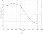
- the use of carbon-dioxide as the nebulizing gas within the nozzle allows for the production of particles with smaller average geometric diameters than the same nozzle configuration with nitrogen as the nebulizing gas, as illustrated in Fig. 6 .
- Nitrogen or air as a nebulizing gas is commonly used in traditional spray dryer nozzles.
- the small geometric diameters of CAN-BD-produced particles produced by a process in which the carbon dioxide is substituted for nitrogen as the drying gas often translate into small aerodynamic diameters, as predicted by Equation 1, if suitable formulation components are incorporated to enhance dispersibility and hollow particle formation.
- the CAN-BD process therefore represents an advancement toward the engineering of respirable particles through the precise control of droplet size to create small geometric diameters; however, the process is highly reliant on formulation composition to achieve small particle aerodynamic diameters and dispersible powders. Improvements to the CAN-BD process that allow for the creation of hollow particles, and thus small aerodynamic diameters, irrespective of, will be of great benefit.
- the disclosure is directed to the incorporation of an improved nozzle into a spray dryer.
- the improved nozzle comprises a variably constrained, divided pathway in which a liquid solution or suspension containing at least one solute or suspended component and an immiscible supercritical or near critical fluid are thoroughly mixed to form a fine emulsion or suspension.
- the emulsion or suspension is released and then subjected to drying in a flowing stream of gas after leaving the nozzle.
- the dry powder thus formed comprises particles of relatively low density.
- the disclosure is directed to a method of providing a respirable fraction of a dry powder for inhalation into the lungs irrespective of the chemical composition of the particles.
- the method comprises the mixing of at least one liquid solution or suspension which contains a solute or solid to be dried, and supercritical or near critical carbon dioxide through a variably constrained, divided pathway into a fine emulsion.
- the emulsion is then subjected to drying in a flowing stream of gas.
- the dry powder thus formed has aerodynamic properties suitable for respiration into the lungs.
- the invention is directed to a method of making a dry powder.
- the method comprises (a) delivering a liquid solution or suspension and an immiscible supercritical or near critical fluid to a flow path, (b) transporting the liquid solution or suspension and the immiscible fluid along the flow path, wherein the flow path includes two or more flow passages of different diameters, at least one flow divider which divides and diverts the flowing mixture into at least two separate passages, wherein the separate passages subsequently intersect to combine their respective flows into a single flowing stream, (c) rapidly reducing the pressure of the single flowing stream, whereby droplets are formed, and (d) passing the droplets through a flow of inert drying gas to form a dry powder.
- the disclosure is also directed to a nebulizing nozzle comprising at least one inlet, a restrictor nozzle outlet, and a flow path in communication with the inlet and the restrictor nozzle outlet, wherein the flow path includes a first passage in communication with the inlet and having a first diameter, followed by a second passage having a second diameter larger than the first diameter, followed by a third passage having a third diameter smaller than the second diameter, followed by a flow divider which divides and diverts flow into at least two separate passages, wherein the separate passages subsequently intersect to combine and form a fourth passage in communication with the restrictor nozzle outlet.
- the methods according to the invention are advantageous in creating particles of low density irrespective of the chemical composition of the particles.
- the dry powders according to the invention are advantageous in comprising particles of morphologies and aerodynamic properties suitable for inhalation into the lungs.
- the present invention provides a method for the creation of relatively low-density particles irrespective of the chemical composition of the particles and, in certain embodiments, provides a method for the creation of low-density particles of aerodynamic properties suitable for inhalation, irrespective of the chemical composition of the particles.
- voids must be created within the particle physically during the spray-drying process.
- Immiscible supercritical or near critical fluids such as supercritical carbon dioxide or near critical carbon dioxide are improved nebulizing mediums for the creation of gas-filled bubbles. After leaving the nozzle, the bubbles may be dried quickly under a stream of warm, dry gas to produce hollow particles.
- the cellular structure of the emulsion forms the basis for a fine plume of droplets to be created once the emulsion is rapidly decompressed to atmospheric pressure.
- Small particles are created by the greater expansion ratio, and thus greater expansion energy, of the liquid carbon dioxide than that of gaseous nitrogen.
- the volume expansion ratio of liquid carbon dioxide is roughly 1:533 (liquid:gas), while the expansion of gaseous nitrogen will simply follow the linear relationship defined by the ideal gas law. Rapid release of pressurized liquid carbon dioxide to atmospheric pressure produces greater energy release and greater atomization of the droplets in the spray plume, ultimately resulting in dried particles of smaller average geometric diameters than the same nozzle conditions with compressed nitrogen as the nebulizing gas.
- carbon dioxide has a much higher solubility in water (about 80-fold) at room temperature than does nitrogen.
- the higher solubility of carbon dioxide and the solvent properties, controlled by pressure, of its liquid phase allow for the dissolution of some of the carbon dioxide in the liquids with which it is mixed.
- the solubility of gases in liquids increases proportionately with increasing pressure, allowing a substantial amount of carbon dioxide to be dissolved in the opposing liquid upon mixing.
- the dissolved carbon dioxide serves as a placeholder within a droplet after leaving the nozzle, and upon return to atmospheric pressure, much of the dissolved carbon dioxide leaves the droplet as a gas, creating hollow regions within the particle.
- the timescale of the oversaturation, followed by vaporization and removal from the droplet, of the dissolved carbon dioxide is slower than the vaporization of the liquid carbon dioxide contained in the emulsion.
- a variably constrained (variable diameter), divided pathway is introduced into the nozzle in place of the simple meeting of two liquid streams which is described in US Patent 6,630,121 .
- a variably constrained (variable diameter), divided pathway is introduced into the nozzle in place of the simple meeting of two liquid streams which is described in US Patent 6,630,121 .
- One embodiment of a nozzle for use in the present invention is shown schematically in Fig. 9 .
- the nozzle invention comprises a similar geometry to the low-volume tee described in US Patent 6,630,121 .
- the two liquid streams meet in the center of the tee, in which partial mixing takes place.
- the flow then progresses through an area of variable constraint, such that the diameter of the flow path is variable, i.e., increased and decreased along the flow path.
- the flow path is initially increased and then decreased.
- the flow path is initially decreased and then increased.
- the variation in constraint may encompass any suitable effective pathway diameter for a desired amount of liquid mixing.
- reference to a flow path passage diameter refers to the inside diameter of a conduit constituting the flow path passage.
- the diameter along the flow path is constrained, i.e., may vary, from about 0.01 mm to about 8 mm. In a more specific embodiment, the diameter is constrained from about 2 mm to about 7 mm.
- the diameter is constrained from about 1.5 mm to about 6 mm. Additionally, the diameter may be constrained in a manner as to produce particles suitable for inhalation. Suitable diameters along the flow path include from about 0.01 mm to about 8 mm, more specifically from about 2 mm to about 7 mm, and even more specifically from about 1.5 mm to about 6 mm. These dimensions are exemplary only and various components of the nozzle may occur in any order, in any number of repetition, and at any distance between the meeting of the supercritical fluid and feed solution or suspension and the restrictor nozzle outlet.
- the flow through the improved nozzle also progresses to an area of flow pathway division, such that the flow stream is divided into two or more branches or separate passages.
- the number of divisions may encompass any suitable effective number for a desired amount of liquid mixing.
- the number of branches comprises from about 2 to about 4.
- the number of branches comprises from 2 or 3.
- the number of branches is 2.
- the number of branches may be comprised in a manner as to produce particles suitable for inhalation.
- the separate passages have respective segments that are parallel to one another.
- the disclosure is directed to a nebulizing nozzle 100 comprising at least one inlet, shown in Fig. 10A as inlets 102 and 104 , a restrictor nozzle outlet 106, and a flow path 108 in communication with the inlet and the restrictor nozzle outlet.
- the flow path includes a mixing T 110, followed by a first passage 112 in communication with the inlets and having a first diameter, followed by a second passage 114 having a second diameter larger than the first diameter, followed by a third passage 116 having a third diameter smaller than the second diameter, followed by a flow divider 118 which divides and diverts flow into at least two separate passages.
- the separate passages have segments 120 and 122, respectively, which are parallel with one another.
- the separate passages subsequently intersect at 124 to combine and form a fourth passage 126 in communication with the restrictor nozzle outlet 106.
- This configuration is exemplary only and various components of the nozzle may occur in any order, in any number of repetition, and at any distance between the meeting of the supercritical fluid and feed solution or suspension and the restrictor nozzle outlet.
- the first diameter is in a range of from about 0.1 to about 3.0 mm
- the second diameter is from about 0.01 to about 8 mm greater than the first diameter
- the third diameter is about 0.01 to about 8 mm less than the second diameter.
- the respective separate passages have diameters greater than the third diameter.
- the fourth passage has a fourth diameter less than the diameters of the respective separate passages.
- the first diameter is in a range of from about 0.1 to about 3.0 mm
- the second diameter is in a range of from about 1.0 to about 6 mm
- the third diameter is in a range of from about 0.1 to about 3.0 mm
- the respective separate passages have diameters in a range of from about 1.0 to about 3.0 mm
- the fourth diameter is in a range of from about 0.1 to about 3.0 mm
- the restrictor nozzle has a diameter of less than about 0.1 mm.
- the length of the flow path over which each diameter is changed from one passage to the next is sufficiently short to achieve good mixing. In one embodiment, there is an abrupt change from one diameter to the next, with no transition area, as shown in Fig. 10A . In another embodiment, the length of the flow path over which each diameter is changed from one passage to the next ranges up to about the larger diameter of the two passages, up to about 0.5 times the larger diameter of the two passages, or up to about 0.25 times the larger diameter of the two passages.
- each passage of a constant diameter may be varied as desired.
- the length of each passage of a constant diameter i.e., each of the first through fourth passages, is of a length of at least the respective diameter of the passage.
- the mass fraction of the liquid does not vary by more than about 25%, more than about 20%, more than about 15%, or more than about 10% throughout the entire lateral cross section of the opening of the nozzle.
- the mass fraction of the liquid solution or suspension comprises from about 5 to about 95% of the mixture.
- the mass fraction of the liquid solution or suspension comprises from about 30 to about 80% of the mixture. In yet a more specific embodiment, the mass fraction of the liquid solution or suspension comprises from about 40 to about 70% of the mixture.
- the mass fraction of solute or suspended component in the liquid may vary widely. In a specific embodiment, the mass fraction of solutes and suspended components in the liquid is in a range of about 0.0001 to about 20%, to about 10%, to about 1% or to about 0.5%. Additionally, the composition of the mixture may be comprised as to produce particles suitable for inhalation. Suitable mass fractions of supercritical or near critical fluid, for example, liquid carbon dioxide, include from about 5% to about 95% of the mixture, more specifically from about 20% to about 70% of the mixture, and even more specifically from about 30% to about 60% of the mixture.
- the liquid solution or suspension may have any desired composition based on the dry powder to be formed by the inventive methods and nozzle.
- the liquid comprises water, an organic solvent-water mixture, or one or more organic solvents.
- a liquid is easily selected depending on the composition of the component which is desired to be provided in dry powder form.
- the liquid comprises water, an alcohol, more specifically, methanol, ethanol, isopropanol, propanol, a butyl alcohol, etc., or a mixture thereof.
- the solute or suspended material may comprise an active agent, examples of which include, but are not limited to, vaccines, insulin, amino acids, peptides, proteins, enzymes, anti-virals, anti-fungals, antibiotics, anti-inflammatory agents, antihistamines, analgesics, anti-cancer agents, antimicrobial agents, immune suppressants, thrombolytics, anticoagulants, central nervous system stimulants, decongestants, diuretic vasodilators, antipsychotics, neurotransmitters, sedatives, hormones, anesthetics, and siRNA.
- the liquid solution or suspension may further include one or more excipients selected from stabilizers, bulking agents, surfactants, antioxidants, and the like.
- the liquid solution or suspension includes a cannabinoid, a polymer binding agent, a dispersing agent, and a bulking agent, and, optionally, an antioxidant, as described in the Sievers et al U.S. Application No. 15/466,719, filed March 22, 2017 .
- Suitable polymer binding agents include polyvinylpyrrolidone (PVP), polyethylene glycol (PEG), poly(lactic-co-glycolic) acid (PLGA), polyvinyl alcohol (PVA), polyacrylic acid (PAA), N-(2-hydroxypropyl) methacrylamide (HPMA), polyoxazoline, polyphosphazenes, xanthan gum, gum arabic, pectins, chitosan derivatives, dextrans, carrageenan, guar gum, cellulose ethers, hyaluronic acid, albumin, and starch.
- PVP polyvinylpyrrolidone
- PEG polyethylene glycol
- PLGA poly(lactic-co-glycolic) acid
- PVA polyvinyl alcohol
- PAA polyacrylic acid
- HPMA N-(2-hydroxypropyl) methacrylamide
- polyoxazoline polyphosphazenes
- xanthan gum gum arabic
- pectins
- Suitable dispersing agents comprise amino acids which act as surfactants, including methionine, alanine, arginine, asparagine, aspartic acid, cysteine, glutamic acid, glutamine, glycine, histidine, isoleucine, leucine, lysine, phenylalanine, proline, serine, threonine, tryptophan, tyrosine, valine, dipalmitoylphosphatidycholine (DPPC), phosphatidic acid (PA), phosphatidylethanolamine (PE), phosphatidylcholine (PC), phosphatidylserine (PS), phosphatidylglycerol (PG), Tween 20, and Tween 80.
- amino acids which act as surfactants including methionine, alanine, arginine, asparagine, aspartic acid, cysteine, glutamic acid, glutamine, glycine, histidine, isoleucine
- Suitable bulking agents comprise a non-hygroscopic polyol such as mannitol, gum Arabic, monosaccharides such as glucose, galactose, fructose, mannose, allose, altrose, fucose, gulose, sorbose, tagatose, arabinose, lyxose, rhamnose, ribose, xylose, erythrose, and threose, disaccharides such as lactose, maltose, sucrose, trehalose, lactulose, cellobiose, chitobiose, allolactose, sucralose, and mannobiose, and polyols such as maltitol, sorbitol, xylitol, erythritol, isomalt, arabitol, ribitol, galactitol, fucitol, iditol, myo-inos
- Suitable antioxidants include, but are not limited to, include vitamin A, vitamin C, vitamin E, alpha-carotene, astaxanthin, beta-carotene, canthaxanthin, lutein, lycopene, zeaxanthin, flavonoids (such as apigenin, myricetin, eriodictyol, theaflavin, genistein, resveratrol, malvidin), cinnamic acid, chicoric acid, chlorogenic acid, rosmarinic acid, curcumin, xanthones, eugenol, citric acid, oxalic acid, and lipoic acid.
- the dispersing agent comprises methionine and an additional antioxidant is not employed.
- At least 30 % of particles have an aerodynamic diameter of less than 5.8 ⁇ m as modeled by an Andersen Cascade Impactor according to US Pharmacopeia ⁇ 601>, and are thus suitable for respiration.
- Such powders will be effectively aerosolized by any dry powder inhaler and deposited in the airways.
- Low-density, easily-aerosolized powders may possess tap densities of 0.01 g/ml to 1 g/ml.
- the particle distribution of the dry powder according to the invention comprises mixture of solid spheres and, importantly, hollow spheres.
- the dry powder contains significantly more hollow spheres as compared to the typical CAN-BD nozzle-prepared powder which does not employ the variable flow path of the invention.
- the dry powder produced according to the invention comprises at least about 20%, at least about 25%, or at least about 30%, hollow spheres.
- the method is conducted at a temperature of not more than about 40 °C.
- the simulated liquid was methanol and the simulated immiscible fluid was supercritical or near critical carbon dioxide.
- the parameters were as follows: a first inlet was simulated to flow 1.5 ⁇ 10 -5 m 3 /s of methanol at a uniform flow rate. A second inlet was simulated to flow 1.5 ⁇ 10 -5 m 3 /s of liquid carbon dioxide at a uniform flow rate. The outlet was set to conditions of 101325 Pa and 293.2 K.
- Fig. 10B The results of the simulation are depicted schematically in Fig. 10B .
- the two streams (dark grey) were mixed nearly completely (mid-scale grey) by the time the flow stream reached the opening of the nozzle.
- the quantitative results of the simulation are shown in Fig. 11 .
- the mass fraction of methanol approaches a value of 0.5 throughout the entire expanse of the lateral cross section of the nozzle opening, demonstrating thorough mixing of the two liquids.
- Dry inhalable powder according to the invention was prepared as described herein.
- a methanol/water solution (7:3 methanol:water) comprising 16% w/w total dissolved solids was made.
- the dissolved solids were composed of 90% w/w mannitol and 10% methionine.
- the solution was divided in half and dried using the previously described CAN-BD process with the following parameters: 2.0 ml/min. carbon dioxide flow rate, 1.0 ml/min. solution flow rate, 40 °C nitrogen drying gas temperature, 40 L/min. nitrogen drying gas flow rate, 75 ⁇ m internal diameter fused silica restrictor, 5 cm long fused silica restrictor, and 0.45 ⁇ m Nylon powder-collection filter.
- the dimensions of the improved nozzle in this example were as follows.
- the 0.35 mm original flowpath diameter expanded to 1.5 mm flowpath diameter, and then narrowed again to 0.35 mm flowpath diameter.
- the flowpath then bifurcated into two pathways of 1.5 mm diameter, then was again constrained to a final 0.35 mm diameter flowpath before exiting the nozzle.
- the resulting powder particles dried from the typical CAN-BD low-volume tee nozzle are shown in scanning electron micrographs (SEMs) in Fig. 13 and Fig. 14 .
- the particles are predominantly solid spheres with occasional evidence of hollow particles scattered throughout the powder, as expected.
- the resulting powder particles dried from the improved nozzle according to the invention are shown in SEMs in Fig. 15 and Fig. 16 .
- the powder particle distribution although comprised of some solid spheres, contains significantly more (about 30%) hollow spheres as compared to the typical CAN-BD nozzle-prepared powder.
Landscapes
- Health & Medical Sciences (AREA)
- Life Sciences & Earth Sciences (AREA)
- Bioinformatics & Cheminformatics (AREA)
- Engineering & Computer Science (AREA)
- Chemical & Material Sciences (AREA)
- Public Health (AREA)
- Veterinary Medicine (AREA)
- Pharmacology & Pharmacy (AREA)
- Epidemiology (AREA)
- Medicinal Chemistry (AREA)
- Animal Behavior & Ethology (AREA)
- General Health & Medical Sciences (AREA)
- Diabetes (AREA)
- Otolaryngology (AREA)
- Pulmonology (AREA)
- Endocrinology (AREA)
- Zoology (AREA)
- Gastroenterology & Hepatology (AREA)
- Immunology (AREA)
- Proteomics, Peptides & Aminoacids (AREA)
- Organic Chemistry (AREA)
- Chemical Kinetics & Catalysis (AREA)
- Medicinal Preparation (AREA)
- Glanulating (AREA)
Claims (16)
- Procédé pour fabriquer une poudre sèche, comprenant (a) la distribution d'une suspension ou d'une solution liquide et d'un fluide quasi-critique ou supercritique non miscible dans une voie d'écoulement, (b) le transport d'un mélange de la suspension ou de la solution liquide et du fluide non miscible le long de la voie d'écoulement, dans lequel la voie d'écoulement inclut deux passages d'écoulement ou plus de différents diamètres, au moins un diviseur d'écoulement qui divise et dévie le mélange en écoulement dans au moins deux passages distincts, dans lequel les passages distincts se recoupent par la suite pour combiner leurs écoulements respectifs en un flux d'écoulement unique, (c) la réduction rapide de la pression du flux d'écoulement unique, moyennant quoi des gouttelettes sont formées, et (d) le passage des gouttelettes à travers un flux de gaz inerte de séchage pour former une poudre sèche.
- Procédé selon la revendication 1, dans lequel la voie d'écoulement inclut un premier passage ayant un premier diamètre, suivi par un deuxième passage ayant un deuxième diamètre supérieur au premier diamètre, suivi par un troisième passage ayant un troisième diamètre inférieur au deuxième diamètre, suivi par le diviseur de flux qui divise et dévie le mélange en écoulement dans au moins deux passages distincts, dans lequel les passages distincts se recoupent par la suite pour combiner leur écoulement respectif en un flux d'écoulement unique.
- Procédé selon la revendication 2, dans lequel le premier diamètre est dans une plage allant d'environ 0,1 à environ 3,0 mm, le deuxième diamètre est supérieur au premier diamètre d'environ 0,01 à environ 8 mm, et le troisième diamètre est inférieur au deuxième diamètre d'environ 0,01 à environ 8 mm.
- Procédé selon la revendication 2 ou 3, dans lequel les passages distincts respectifs ont des diamètres égaux au premier diamètre.
- Procédé selon l'une quelconque des revendications 2 à 4, dans lequel les écoulements respectifs provenant des passages distincts sont combinés en un flux d'écoulement unique dans un quatrième passage ayant un quatrième diamètre inférieur aux diamètres des passages distincts respectifs.
- Procédé selon l'une quelconque des revendications 2 à 5, dans lequel le premier diamètre est dans une plage allant d'environ 0,1 à environ 3,0 mm, le deuxième diamètre est dans une plage allant d'environ 1,0 à environ 6 mm, le troisième diamètre est dans une plage allant d'environ 0,1 à environ 3,0 mm, les passages distincts respectifs ont des diamètres dans une plage allant d'environ 1,0 mm à environ 3,0 mm, et le quatrième diamètre est dans une plage allant d'environ 0,1 à environ 3,0 mm.
- Procédé selon l'une quelconque des revendications 1 à 6, dans lequel le diviseur d'écoulement divise et dévie le mélange en écoulement dans deux, trois ou quatre passages distincts qui par la suite se recoupent pour combiner leurs écoulements respectifs en un flux d'écoulement unique.
- Procédé selon l'une quelconque des revendications 1 à 6, dans lequel les passages distincts ont des segments respectifs qui sont parallèles les uns aux autres.
- Procédé selon l'une quelconque des revendications 1 à 8, dans lequel la pression du flux d'écoulement unique est réduite en passant le flux à travers une buse de réduction.
- Procédé selon la revendication 8, dans lequel la buse de réduction a un diamètre inférieur à environ 0,1 mm.
- Procédé selon l'une quelconque des revendications 1 à 10, dans lequel le fluide quasi-critique ou supercritique est du dioxyde de carbone.
- Procédé selon l'une quelconque des revendications 1 à 11, dans lequel la suspension ou la solution liquide comprend au moins un ingrédient actif.
- Procédé selon la revendication 12, dans lequel l'ingrédient actif comprend au moins un vaccin, de l'insuline, un acide aminé, un peptide, une protéine, une enzyme, un anti-viral, un anti-fongique, un antibiotique, un agent anti-inflammatoire, un antihistaminique, un analgésique, un agent anticancéreux, un agent antimicrobien, un immunosuppresseur, un thrombolytique, un anticoagulant, un stimulant du système nerveux central, un décongestionnant, un vasodilatateur diurétique, un antipsychotique, un neurotransmetteur, un sédatif, une hormone, un anesthésique ou un siARN.
- Procédé selon l'une quelconque des revendications 1 à 13, dans lequel la poudre sèche comprend au moins 30 % de particules d'une taille inférieure à 5,8 µm telles que modélisées par un impacteur en cascade Andersen selon US Pharmacopeia <601>.
- Procédé selon l'une quelconque des revendications 1 à 14, dans lequel le gaz de séchage est l'azote ou le dioxyde de carbone.
- Procédé selon l'une quelconque des revendications 1 à 15, dans lequel le procédé est appliqué à une température ne dépassant pas environ 40 °C.
Applications Claiming Priority (1)
| Application Number | Priority Date | Filing Date | Title |
|---|---|---|---|
| US15/669,118 US10206873B1 (en) | 2017-08-04 | 2017-08-04 | Dry powder formation using a variably constrained, divided pathway for mixing fluid streams |
Publications (2)
| Publication Number | Publication Date |
|---|---|
| EP3437635A1 EP3437635A1 (fr) | 2019-02-06 |
| EP3437635B1 true EP3437635B1 (fr) | 2020-05-13 |
Family
ID=63113416
Family Applications (1)
| Application Number | Title | Priority Date | Filing Date |
|---|---|---|---|
| EP18186749.0A Active EP3437635B1 (fr) | 2017-08-04 | 2018-08-01 | Formation de poudre sèche en utilisant une voie divisée à contrainte variable pour mélanger des courants de fluide |
Country Status (5)
| Country | Link |
|---|---|
| US (1) | US10206873B1 (fr) |
| EP (1) | EP3437635B1 (fr) |
| AU (1) | AU2018208673B2 (fr) |
| CA (1) | CA3013126A1 (fr) |
| IL (1) | IL260801B (fr) |
Family Cites Families (18)
| Publication number | Priority date | Publication date | Assignee | Title |
|---|---|---|---|---|
| US5611344A (en) | 1996-03-05 | 1997-03-18 | Acusphere, Inc. | Microencapsulated fluorinated gases for use as imaging agents |
| EP1185248B1 (fr) * | 1999-06-09 | 2012-05-02 | Robert E. Sievers | Nebulisation et sechage de bulles assiste par un fluide supercritique |
| FR2803538B1 (fr) | 1999-12-15 | 2002-06-07 | Separex Sa | Procede et dispositif de captage de fines particules par percolation dans un lit de granules |
| US6589557B2 (en) | 2000-06-15 | 2003-07-08 | Acusphere, Inc. | Porous celecoxib matrices and methods of manufacture thereof |
| IL157346A0 (en) | 2001-02-26 | 2004-02-19 | Dompe Spa | Apparatus and method for micron and submicron particle formation |
| EP1414633A4 (fr) | 2001-07-10 | 2005-01-26 | Univ Technology Corp | Dispositifs et procedes de production de particules |
| JP4374249B2 (ja) | 2001-10-22 | 2009-12-02 | ドンペ ピーエイチエー.アール.エムエー エス.ピー.エー. | 超臨界的流体による処理方法:タンパク質微粒子の調製およびそれらの安定化 |
| JP2005514188A (ja) | 2001-12-07 | 2005-05-19 | エイフェル テクノロジーズ リミテッド | 小粒子の合成 |
| KR20050011741A (ko) * | 2002-04-11 | 2005-01-29 | 메드이뮨 백신즈 인코포레이티드 | 분무 건조에 의한 생물학적 활성 물질의 보존 |
| KR20050088175A (ko) * | 2002-12-17 | 2005-09-02 | 메드이뮨 백신즈 인코포레이티드 | 생물활성 물질의 고압 분무 건조 |
| US6931888B2 (en) | 2003-02-07 | 2005-08-23 | Ferro Corporation | Lyophilization method and apparatus for producing particles |
| WO2005005010A2 (fr) | 2003-02-21 | 2005-01-20 | Ferro Corporation | Procedes et appareil de production de particules composites utilisant un fluide supercritique comme agent plastifiant et d'extraction |
| US7455797B2 (en) | 2003-02-28 | 2008-11-25 | Ferro Corporation | Method and apparatus for producing particles using supercritical fluid |
| US20060008531A1 (en) | 2003-05-08 | 2006-01-12 | Ferro Corporation | Method for producing solid-lipid composite drug particles |
| US7279181B2 (en) | 2003-06-03 | 2007-10-09 | Ferro Corporation | Method for preparation of particles from solution-in-supercritical fluid or compressed gas emulsions |
| SE0303476D0 (sv) | 2003-12-22 | 2003-12-22 | Censdelivery Ab | Device, method and use for the formation of small particles |
| US20060105051A1 (en) | 2004-11-18 | 2006-05-18 | Blair Jackson | Manufacture of particles for pulmonary drug delivery by carbon dioxide assisted nebulization |
| US20110150703A1 (en) | 2008-07-18 | 2011-06-23 | Castro Gustavo H | Tortuous path static mixers and fluid systems including the same |
-
2017
- 2017-08-04 US US15/669,118 patent/US10206873B1/en active Active
-
2018
- 2018-07-25 AU AU2018208673A patent/AU2018208673B2/en not_active Expired - Fee Related
- 2018-07-26 IL IL260801A patent/IL260801B/en unknown
- 2018-08-01 EP EP18186749.0A patent/EP3437635B1/fr active Active
- 2018-08-02 CA CA3013126A patent/CA3013126A1/fr active Pending
Non-Patent Citations (1)
| Title |
|---|
| None * |
Also Published As
| Publication number | Publication date |
|---|---|
| AU2018208673A1 (en) | 2019-02-21 |
| AU2018208673B2 (en) | 2022-08-04 |
| US10206873B1 (en) | 2019-02-19 |
| CA3013126A1 (fr) | 2019-02-04 |
| IL260801A (en) | 2019-01-31 |
| IL260801B (en) | 2022-03-01 |
| EP3437635A1 (fr) | 2019-02-06 |
| US20190038552A1 (en) | 2019-02-07 |
Similar Documents
| Publication | Publication Date | Title |
|---|---|---|
| Chaurasiya et al. | Dry powder for pulmonary delivery: A comprehensive review | |
| Ziaee et al. | Spray drying of pharmaceuticals and biopharmaceuticals: Critical parameters and experimental process optimization approaches | |
| Chow et al. | Particle engineering for pulmonary drug delivery | |
| López-Iglesias et al. | From the printer to the lungs: Inkjet-printed aerogel particles for pulmonary delivery | |
| Focaroli et al. | A Design of Experiment (DoE) approach to optimise spray drying process conditions for the production of trehalose/leucine formulations with application in pulmonary delivery | |
| Lin et al. | Powder production and particle engineering for dry powder inhaler formulations | |
| JP4837892B2 (ja) | 粉末バッチを製造する方法 | |
| Elversson et al. | Droplet and particle size relationship and shell thickness of inhalable lactose particles during spray drying | |
| Sievers et al. | Micronization of water-soluble or alcohol-soluble pharmaceuticals and model compounds with a low-temperature Bubble Dryer® | |
| US20020187106A1 (en) | Methods for tobramycin inhalation | |
| JP2009519972A (ja) | 粒子ベースの経肺投与または経鼻投与用製薬の製造方法 | |
| Gharse et al. | Large porous hollow particles: lightweight champions of pulmonary drug delivery | |
| EP1976486A1 (fr) | Procede de production de microparticules poreuses | |
| JP7236485B2 (ja) | 三流体ノズルを用いた吸入用複合粒子の製造方法 | |
| Henriques et al. | Spray dried powders for nasal delivery: Process and formulation considerations | |
| EP3526533A1 (fr) | Procédé de fabrication de compositions séchées par pulvérisation et appareil de séchage par pulvérisation | |
| Wanning et al. | Jet-vortex spray freeze drying for the production of inhalable lyophilisate powders | |
| Rostamnezhad et al. | Spray freeze-drying for inhalation application: process and formulation variables | |
| EP3437635B1 (fr) | Formation de poudre sèche en utilisant une voie divisée à contrainte variable pour mélanger des courants de fluide | |
| Wang et al. | Inhalable microparticle platform based on a novel shell-forming lipid excipient and its feasibility for respirable delivery of biologics | |
| Foster et al. | Particle engineering by dense gas technologies applied to pharmaceuticals | |
| El-Gendy et al. | Particle engineering technologies for pulmonary drug delivery | |
| Zakharyuta et al. | Inkjet printing platform for fabrication of uniform, excipient-free drug particles for pulmonary delivery in a preclinical setting | |
| Shoyele | Engineering protein particles for pulmonary drug delivery | |
| Pyo | Two different shapes of insulin microparticles produced by solution enhanced dispersion supercritical fluid (SEDS) process |
Legal Events
| Date | Code | Title | Description |
|---|---|---|---|
| PUAI | Public reference made under article 153(3) epc to a published international application that has entered the european phase |
Free format text: ORIGINAL CODE: 0009012 |
|
| STAA | Information on the status of an ep patent application or granted ep patent |
Free format text: STATUS: THE APPLICATION HAS BEEN PUBLISHED |
|
| AK | Designated contracting states |
Kind code of ref document: A1 Designated state(s): AL AT BE BG CH CY CZ DE DK EE ES FI FR GB GR HR HU IE IS IT LI LT LU LV MC MK MT NL NO PL PT RO RS SE SI SK SM TR |
|
| AX | Request for extension of the european patent |
Extension state: BA ME |
|
| STAA | Information on the status of an ep patent application or granted ep patent |
Free format text: STATUS: REQUEST FOR EXAMINATION WAS MADE |
|
| 17P | Request for examination filed |
Effective date: 20190806 |
|
| RBV | Designated contracting states (corrected) |
Designated state(s): AL AT BE BG CH CY CZ DE DK EE ES FI FR GB GR HR HU IE IS IT LI LT LU LV MC MK MT NL NO PL PT RO RS SE SI SK SM TR |
|
| STAA | Information on the status of an ep patent application or granted ep patent |
Free format text: STATUS: EXAMINATION IS IN PROGRESS |
|
| 17Q | First examination report despatched |
Effective date: 20190924 |
|
| GRAP | Despatch of communication of intention to grant a patent |
Free format text: ORIGINAL CODE: EPIDOSNIGR1 |
|
| STAA | Information on the status of an ep patent application or granted ep patent |
Free format text: STATUS: GRANT OF PATENT IS INTENDED |
|
| INTG | Intention to grant announced |
Effective date: 20191210 |
|
| RIN1 | Information on inventor provided before grant (corrected) |
Inventor name: GILDELAMADRID, XUNO Inventor name: SIEVERS, ROBERT E. |
|
| GRAS | Grant fee paid |
Free format text: ORIGINAL CODE: EPIDOSNIGR3 |
|
| GRAA | (expected) grant |
Free format text: ORIGINAL CODE: 0009210 |
|
| STAA | Information on the status of an ep patent application or granted ep patent |
Free format text: STATUS: THE PATENT HAS BEEN GRANTED |
|
| AK | Designated contracting states |
Kind code of ref document: B1 Designated state(s): AL AT BE BG CH CY CZ DE DK EE ES FI FR GB GR HR HU IE IS IT LI LT LU LV MC MK MT NL NO PL PT RO RS SE SI SK SM TR |
|
| REG | Reference to a national code |
Ref country code: GB Ref legal event code: FG4D |
|
| REG | Reference to a national code |
Ref country code: CH Ref legal event code: EP |
|
| REG | Reference to a national code |
Ref country code: DE Ref legal event code: R096 Ref document number: 602018004474 Country of ref document: DE |
|
| REG | Reference to a national code |
Ref country code: AT Ref legal event code: REF Ref document number: 1269328 Country of ref document: AT Kind code of ref document: T Effective date: 20200615 |
|
| REG | Reference to a national code |
Ref country code: CH Ref legal event code: NV Representative=s name: RENTSCH PARTNER AG, CH Ref country code: CH Ref legal event code: PUE Owner name: KELSIE BIOTECH CORPORATION, US Free format text: FORMER OWNER: COLORADO CAN LLC, US |
|
| REG | Reference to a national code |
Ref country code: LT Ref legal event code: MG4D |
|
| REG | Reference to a national code |
Ref country code: NL Ref legal event code: MP Effective date: 20200513 |
|
| PG25 | Lapsed in a contracting state [announced via postgrant information from national office to epo] |
Ref country code: PT Free format text: LAPSE BECAUSE OF FAILURE TO SUBMIT A TRANSLATION OF THE DESCRIPTION OR TO PAY THE FEE WITHIN THE PRESCRIBED TIME-LIMIT Effective date: 20200914 Ref country code: IS Free format text: LAPSE BECAUSE OF FAILURE TO SUBMIT A TRANSLATION OF THE DESCRIPTION OR TO PAY THE FEE WITHIN THE PRESCRIBED TIME-LIMIT Effective date: 20200913 Ref country code: GR Free format text: LAPSE BECAUSE OF FAILURE TO SUBMIT A TRANSLATION OF THE DESCRIPTION OR TO PAY THE FEE WITHIN THE PRESCRIBED TIME-LIMIT Effective date: 20200814 Ref country code: LT Free format text: LAPSE BECAUSE OF FAILURE TO SUBMIT A TRANSLATION OF THE DESCRIPTION OR TO PAY THE FEE WITHIN THE PRESCRIBED TIME-LIMIT Effective date: 20200513 Ref country code: SE Free format text: LAPSE BECAUSE OF FAILURE TO SUBMIT A TRANSLATION OF THE DESCRIPTION OR TO PAY THE FEE WITHIN THE PRESCRIBED TIME-LIMIT Effective date: 20200513 Ref country code: NO Free format text: LAPSE BECAUSE OF FAILURE TO SUBMIT A TRANSLATION OF THE DESCRIPTION OR TO PAY THE FEE WITHIN THE PRESCRIBED TIME-LIMIT Effective date: 20200813 Ref country code: FI Free format text: LAPSE BECAUSE OF FAILURE TO SUBMIT A TRANSLATION OF THE DESCRIPTION OR TO PAY THE FEE WITHIN THE PRESCRIBED TIME-LIMIT Effective date: 20200513 |
|
| PG25 | Lapsed in a contracting state [announced via postgrant information from national office to epo] |
Ref country code: BG Free format text: LAPSE BECAUSE OF FAILURE TO SUBMIT A TRANSLATION OF THE DESCRIPTION OR TO PAY THE FEE WITHIN THE PRESCRIBED TIME-LIMIT Effective date: 20200813 Ref country code: LV Free format text: LAPSE BECAUSE OF FAILURE TO SUBMIT A TRANSLATION OF THE DESCRIPTION OR TO PAY THE FEE WITHIN THE PRESCRIBED TIME-LIMIT Effective date: 20200513 Ref country code: HR Free format text: LAPSE BECAUSE OF FAILURE TO SUBMIT A TRANSLATION OF THE DESCRIPTION OR TO PAY THE FEE WITHIN THE PRESCRIBED TIME-LIMIT Effective date: 20200513 Ref country code: RS Free format text: LAPSE BECAUSE OF FAILURE TO SUBMIT A TRANSLATION OF THE DESCRIPTION OR TO PAY THE FEE WITHIN THE PRESCRIBED TIME-LIMIT Effective date: 20200513 |
|
| REG | Reference to a national code |
Ref country code: AT Ref legal event code: MK05 Ref document number: 1269328 Country of ref document: AT Kind code of ref document: T Effective date: 20200513 |
|
| RAP2 | Party data changed (patent owner data changed or rights of a patent transferred) |
Owner name: KELSIE BIOTECH CORPORATION |
|
| PG25 | Lapsed in a contracting state [announced via postgrant information from national office to epo] |
Ref country code: AL Free format text: LAPSE BECAUSE OF FAILURE TO SUBMIT A TRANSLATION OF THE DESCRIPTION OR TO PAY THE FEE WITHIN THE PRESCRIBED TIME-LIMIT Effective date: 20200513 Ref country code: NL Free format text: LAPSE BECAUSE OF FAILURE TO SUBMIT A TRANSLATION OF THE DESCRIPTION OR TO PAY THE FEE WITHIN THE PRESCRIBED TIME-LIMIT Effective date: 20200513 |
|
| REG | Reference to a national code |
Ref country code: DE Ref legal event code: R081 Ref document number: 602018004474 Country of ref document: DE Owner name: KELSIE BIOTECH CORPORATION, ENGLEWOOD, US Free format text: FORMER OWNER: COLORADO CAN LLC, BOULDER, CO, US |
|
| PG25 | Lapsed in a contracting state [announced via postgrant information from national office to epo] |
Ref country code: DK Free format text: LAPSE BECAUSE OF FAILURE TO SUBMIT A TRANSLATION OF THE DESCRIPTION OR TO PAY THE FEE WITHIN THE PRESCRIBED TIME-LIMIT Effective date: 20200513 Ref country code: EE Free format text: LAPSE BECAUSE OF FAILURE TO SUBMIT A TRANSLATION OF THE DESCRIPTION OR TO PAY THE FEE WITHIN THE PRESCRIBED TIME-LIMIT Effective date: 20200513 Ref country code: AT Free format text: LAPSE BECAUSE OF FAILURE TO SUBMIT A TRANSLATION OF THE DESCRIPTION OR TO PAY THE FEE WITHIN THE PRESCRIBED TIME-LIMIT Effective date: 20200513 Ref country code: ES Free format text: LAPSE BECAUSE OF FAILURE TO SUBMIT A TRANSLATION OF THE DESCRIPTION OR TO PAY THE FEE WITHIN THE PRESCRIBED TIME-LIMIT Effective date: 20200513 Ref country code: CZ Free format text: LAPSE BECAUSE OF FAILURE TO SUBMIT A TRANSLATION OF THE DESCRIPTION OR TO PAY THE FEE WITHIN THE PRESCRIBED TIME-LIMIT Effective date: 20200513 Ref country code: RO Free format text: LAPSE BECAUSE OF FAILURE TO SUBMIT A TRANSLATION OF THE DESCRIPTION OR TO PAY THE FEE WITHIN THE PRESCRIBED TIME-LIMIT Effective date: 20200513 Ref country code: IT Free format text: LAPSE BECAUSE OF FAILURE TO SUBMIT A TRANSLATION OF THE DESCRIPTION OR TO PAY THE FEE WITHIN THE PRESCRIBED TIME-LIMIT Effective date: 20200513 Ref country code: SM Free format text: LAPSE BECAUSE OF FAILURE TO SUBMIT A TRANSLATION OF THE DESCRIPTION OR TO PAY THE FEE WITHIN THE PRESCRIBED TIME-LIMIT Effective date: 20200513 |
|
| REG | Reference to a national code |
Ref country code: DE Ref legal event code: R097 Ref document number: 602018004474 Country of ref document: DE |
|
| REG | Reference to a national code |
Ref country code: GB Ref legal event code: 732E Free format text: REGISTERED BETWEEN 20210121 AND 20210127 |
|
| PG25 | Lapsed in a contracting state [announced via postgrant information from national office to epo] |
Ref country code: SK Free format text: LAPSE BECAUSE OF FAILURE TO SUBMIT A TRANSLATION OF THE DESCRIPTION OR TO PAY THE FEE WITHIN THE PRESCRIBED TIME-LIMIT Effective date: 20200513 Ref country code: PL Free format text: LAPSE BECAUSE OF FAILURE TO SUBMIT A TRANSLATION OF THE DESCRIPTION OR TO PAY THE FEE WITHIN THE PRESCRIBED TIME-LIMIT Effective date: 20200513 |
|
| PLBE | No opposition filed within time limit |
Free format text: ORIGINAL CODE: 0009261 |
|
| STAA | Information on the status of an ep patent application or granted ep patent |
Free format text: STATUS: NO OPPOSITION FILED WITHIN TIME LIMIT |
|
| PG25 | Lapsed in a contracting state [announced via postgrant information from national office to epo] |
Ref country code: MC Free format text: LAPSE BECAUSE OF FAILURE TO SUBMIT A TRANSLATION OF THE DESCRIPTION OR TO PAY THE FEE WITHIN THE PRESCRIBED TIME-LIMIT Effective date: 20200513 |
|
| 26N | No opposition filed |
Effective date: 20210216 |
|
| PG25 | Lapsed in a contracting state [announced via postgrant information from national office to epo] |
Ref country code: LU Free format text: LAPSE BECAUSE OF NON-PAYMENT OF DUE FEES Effective date: 20200801 |
|
| REG | Reference to a national code |
Ref country code: BE Ref legal event code: MM Effective date: 20200831 |
|
| PG25 | Lapsed in a contracting state [announced via postgrant information from national office to epo] |
Ref country code: SI Free format text: LAPSE BECAUSE OF FAILURE TO SUBMIT A TRANSLATION OF THE DESCRIPTION OR TO PAY THE FEE WITHIN THE PRESCRIBED TIME-LIMIT Effective date: 20200513 |
|
| PG25 | Lapsed in a contracting state [announced via postgrant information from national office to epo] |
Ref country code: FR Free format text: LAPSE BECAUSE OF NON-PAYMENT OF DUE FEES Effective date: 20200831 |
|
| PG25 | Lapsed in a contracting state [announced via postgrant information from national office to epo] |
Ref country code: BE Free format text: LAPSE BECAUSE OF NON-PAYMENT OF DUE FEES Effective date: 20200831 Ref country code: IE Free format text: LAPSE BECAUSE OF NON-PAYMENT OF DUE FEES Effective date: 20200801 |
|
| PG25 | Lapsed in a contracting state [announced via postgrant information from national office to epo] |
Ref country code: TR Free format text: LAPSE BECAUSE OF FAILURE TO SUBMIT A TRANSLATION OF THE DESCRIPTION OR TO PAY THE FEE WITHIN THE PRESCRIBED TIME-LIMIT Effective date: 20200513 Ref country code: MT Free format text: LAPSE BECAUSE OF FAILURE TO SUBMIT A TRANSLATION OF THE DESCRIPTION OR TO PAY THE FEE WITHIN THE PRESCRIBED TIME-LIMIT Effective date: 20200513 Ref country code: CY Free format text: LAPSE BECAUSE OF FAILURE TO SUBMIT A TRANSLATION OF THE DESCRIPTION OR TO PAY THE FEE WITHIN THE PRESCRIBED TIME-LIMIT Effective date: 20200513 |
|
| PG25 | Lapsed in a contracting state [announced via postgrant information from national office to epo] |
Ref country code: MK Free format text: LAPSE BECAUSE OF FAILURE TO SUBMIT A TRANSLATION OF THE DESCRIPTION OR TO PAY THE FEE WITHIN THE PRESCRIBED TIME-LIMIT Effective date: 20200513 |
|
| PGFP | Annual fee paid to national office [announced via postgrant information from national office to epo] |
Ref country code: GB Payment date: 20220810 Year of fee payment: 5 Ref country code: DE Payment date: 20220818 Year of fee payment: 5 |
|
| PGFP | Annual fee paid to national office [announced via postgrant information from national office to epo] |
Ref country code: CH Payment date: 20220901 Year of fee payment: 5 |
|
| P01 | Opt-out of the competence of the unified patent court (upc) registered |
Effective date: 20230523 |
|
| REG | Reference to a national code |
Ref country code: DE Ref legal event code: R119 Ref document number: 602018004474 Country of ref document: DE |
|
| REG | Reference to a national code |
Ref country code: CH Ref legal event code: PL |
|
| GBPC | Gb: european patent ceased through non-payment of renewal fee |
Effective date: 20230801 |
|
| PG25 | Lapsed in a contracting state [announced via postgrant information from national office to epo] |
Ref country code: CH Free format text: LAPSE BECAUSE OF NON-PAYMENT OF DUE FEES Effective date: 20230831 |