EP3437580A1 - Forceps-type treatment instrument - Google Patents
Forceps-type treatment instrument Download PDFInfo
- Publication number
- EP3437580A1 EP3437580A1 EP17775245.8A EP17775245A EP3437580A1 EP 3437580 A1 EP3437580 A1 EP 3437580A1 EP 17775245 A EP17775245 A EP 17775245A EP 3437580 A1 EP3437580 A1 EP 3437580A1
- Authority
- EP
- European Patent Office
- Prior art keywords
- forceps
- shaft
- protrusion
- forceps piece
- end portion
- Prior art date
- Legal status (The legal status is an assumption and is not a legal conclusion. Google has not performed a legal analysis and makes no representation as to the accuracy of the status listed.)
- Granted
Links
Images









Classifications
-
- A—HUMAN NECESSITIES
- A61—MEDICAL OR VETERINARY SCIENCE; HYGIENE
- A61B—DIAGNOSIS; SURGERY; IDENTIFICATION
- A61B18/00—Surgical instruments, devices or methods for transferring non-mechanical forms of energy to or from the body
- A61B18/04—Surgical instruments, devices or methods for transferring non-mechanical forms of energy to or from the body by heating
- A61B18/12—Surgical instruments, devices or methods for transferring non-mechanical forms of energy to or from the body by heating by passing a current through the tissue to be heated, e.g. high-frequency current
- A61B18/14—Probes or electrodes therefor
- A61B18/1442—Probes having pivoting end effectors, e.g. forceps
-
- A—HUMAN NECESSITIES
- A61—MEDICAL OR VETERINARY SCIENCE; HYGIENE
- A61B—DIAGNOSIS; SURGERY; IDENTIFICATION
- A61B18/00—Surgical instruments, devices or methods for transferring non-mechanical forms of energy to or from the body
- A61B18/04—Surgical instruments, devices or methods for transferring non-mechanical forms of energy to or from the body by heating
- A61B18/12—Surgical instruments, devices or methods for transferring non-mechanical forms of energy to or from the body by heating by passing a current through the tissue to be heated, e.g. high-frequency current
-
- A—HUMAN NECESSITIES
- A61—MEDICAL OR VETERINARY SCIENCE; HYGIENE
- A61B—DIAGNOSIS; SURGERY; IDENTIFICATION
- A61B18/00—Surgical instruments, devices or methods for transferring non-mechanical forms of energy to or from the body
- A61B18/04—Surgical instruments, devices or methods for transferring non-mechanical forms of energy to or from the body by heating
- A61B18/12—Surgical instruments, devices or methods for transferring non-mechanical forms of energy to or from the body by heating by passing a current through the tissue to be heated, e.g. high-frequency current
- A61B18/14—Probes or electrodes therefor
- A61B18/1492—Probes or electrodes therefor having a flexible, catheter-like structure, e.g. for heart ablation
-
- A—HUMAN NECESSITIES
- A61—MEDICAL OR VETERINARY SCIENCE; HYGIENE
- A61B—DIAGNOSIS; SURGERY; IDENTIFICATION
- A61B17/00—Surgical instruments, devices or methods
- A61B17/28—Surgical forceps
- A61B17/29—Forceps for use in minimally invasive surgery
- A61B2017/2926—Details of heads or jaws
- A61B2017/2932—Transmission of forces to jaw members
- A61B2017/2939—Details of linkages or pivot points
-
- A—HUMAN NECESSITIES
- A61—MEDICAL OR VETERINARY SCIENCE; HYGIENE
- A61B—DIAGNOSIS; SURGERY; IDENTIFICATION
- A61B17/00—Surgical instruments, devices or methods
- A61B17/28—Surgical forceps
- A61B17/29—Forceps for use in minimally invasive surgery
- A61B2017/2947—Pivots
-
- A—HUMAN NECESSITIES
- A61—MEDICAL OR VETERINARY SCIENCE; HYGIENE
- A61B—DIAGNOSIS; SURGERY; IDENTIFICATION
- A61B18/00—Surgical instruments, devices or methods for transferring non-mechanical forms of energy to or from the body
- A61B2018/00571—Surgical instruments, devices or methods for transferring non-mechanical forms of energy to or from the body for achieving a particular surgical effect
- A61B2018/00589—Coagulation
Definitions
- the present invention relates to a forceps type treatment instrument which performs a treatment such as hemostasis by a high-frequency current using, for example, an endoscope.
- a bipolar hemostat as an example of a forceps type treatment instrument is a device which opens and closes a pair of electrodes (forceps pieces) disposed at a front end of a sheath passing through a treatment instrument guide tube of an endoscope by the operation of an operation part provided at a rear end of the sheath and allowing a high-frequency current to flow to a biological tissue such as a blood vessel while gripping the biological tissue with the high-frequency electrodes so that the tissue in the vicinity of the grip portion is burned and coagulated and hemostasis is performed.
- electrodes forceps pieces
- each of the pair of electrodes includes a shaft hole corresponding to a rotation center and is rotatably and axially supported by a pair of shaft portions of an insulation spacer member for electrically insulating both members from each other. Then, a front end portion of the shaft portion of the insulation spacer member is fitted to a fitting hole of each of a pair of arm portions of a forceps support member provided at the front end of the sheath to be attached thereto.
- the opening and closing angle (the opening degree) of the pair of electrodes is defined in such a manner that a circular-arc concave groove is formed in an insulation spacer at a contact surface (sliding surface) between the insulation spacer and the electrode, a convex protrusion is formed in the electrode to be loosely fitted to the groove, and the protrusion comes into contact with both end portions of the groove with the rotation of the electrode.
- the opening and closing angle of the pair of electrodes is defined by the circular-arc concave groove formed in the insulation spacer member at the contact surface (the sliding surface) between the insulation spacer member and the electrode and the convex protrusion formed in the electrode to be loosely fitted to the groove.
- only small protrusion can be formed in structure or dimension and a contact portion between the protrusion portion and the end portion of the groove cannot be formed to be sufficiently large.
- the protrusion since the protrusion is not stopped by the end portion of the groove and is separated from the groove (the protrusion gets on the outer portion from the end portion of the groove) when a relatively strong rotation force is applied to the electrode, there is concern that the electrode opening and closing operation may be disturbed.
- the end portion of the groove may be partially cut.
- the shaft portion supporting the electrode of the insulation spacer member and the fitting hole formed in the arm portion of the forceps support member so that the shaft portion is fitted to the fitting hole have a circular cross-section (in a cross-section orthogonal to the axis)
- the insulation spacer member may rotate with respect to the forceps support member at the time of opening and closing the electrode (particularly, at the time of closing the electrode).
- the posture of the electrode becomes unstable, the posture may be different from the posture that is desired by an operator.
- Patent Document 1 JP 2014-188160 A
- the present invention has been made in view of such circumstances and an object of the present invention is to provide a forceps type treatment instrument capable of stably opening and closing forceps pieces. Further, another object of the present invention is to provide a forceps type treatment instrument capable of stabilizing a forceps piece opening and closing posture at the time of opening and closing forceps pieces.
- a forceps type treatment instrument including: a forceps support member that includes a first arm portion and a second arm portion attached to a distal end of a sheath and facing each other; a first forceps piece and a second forceps piece which are interposed between the first arm portion and the second arm portion of the forceps support member; and a spacer member that rotatably supports each of the first forceps piece and the second forceps piece, in which the first forceps piece includes a first shaft hole, in which the second forceps piece includes a second shaft hole, in which the spacer member includes a first shaft portion rotatably inserted into the first shaft hole and a second shaft portion rotatably inserted into the second shaft hole, in which the spacer member is provided with a first protrusion portion and a second protrusion portion, in which an inner peripheral surface of the first shaft hole is provided with a first notch portion, in which an inner peripheral surface of the second shaft hole
- the spacer member is provided with the protrusion portion (the first protrusion portion, the second protrusion portion) and the inner peripheral surface of the shaft hole of the forceps piece is provided with the notch portion (the first notch portion, the second notch portion) having the end portion (the first end portion, the third end portion) into which the protrusion portion comes into contact.
- the protrusion portion can be reliably stopped by the end portion of the notch portion, it is possible to stably open and close the forceps pieces. Since it is possible to prevent the protrusion portion from being separated from the notch portion, it is possible to reduce the scraping due to the sliding of the notch portion or the protrusion portion, to reduce the damage of the components, and to improve the durability.
- the first protrusion portion may come into contact with the second end portion when the first forceps piece is rotated in the second direction, and the second protrusion portion may come into contact with the fourth end portion when the second forceps piece is rotated in the first direction.
- the rotatable range or the opening degree of the forceps piece can be defined in both forceps piece opening and closing directions.
- the first protrusion portion may be provided to protrude from an outer surface of the first shaft portion
- the second protrusion portion may be provided to protrude from an outer surface of the second shaft portion
- the protrusion portion When the protrusion portion is provided so as to protrude from the outer surface of the shaft portion (the first shaft portion, the second shaft portion) of the spacer, the protrusion portion is reinforced by the shaft portion. For this reason, since it is possible to ensure a sufficient strength without increasing the size of the protrusion portion and to integrally mold the protrusion portion with the spacer, it is possible to decrease a manufacturing cost.
- a forceps type treatment instrument including: a forceps support member that includes a first arm portion and a second arm portion attached to a distal end of a sheath and facing each other; a first forceps piece and a second forceps piece which are interposed between the first arm portion and the second arm portion of the forceps support member; and a spacer member that rotatably supports each of the first forceps piece and the second forceps piece, in which the first forceps piece includes a first shaft hole, in which the second forceps piece includes a second shaft hole, in which the spacer member includes a first shaft portion rotatably inserted into the first shaft hole and a second shaft portion rotatably inserted into the second shaft hole, in which the first arm portion includes a first fitting hole into which a front end portion of the first shaft portion is fitted, in which the second arm portion includes a second fitting hole into which a front end portion of the second shaft portion is fitted, in which
- the cutout portion is provided in at least one of the first fitting hole and the front end portion of the first shaft portion and the complementary portion which complements the cutout portion is provided at the other thereof.
- the direction of the distal end of the forceps portion including the pair of forceps pieces rotating with respect to the spacer member to be opened and closed may be inclined with respect to the forceps support member.
- the forceps type treatment instrument according to the second aspect of the present invention since it is possible to reduce such concern, it is possible to provide a forceps type treatment instrument having excellent operability.
- a cutout portion may be provided in at least one of the second fitting hole and the front end portion of the second shaft portion, and a complementary portion which complements the cutout portion may be provided in at least the other one of the second fitting hole and the front end portion of the second shaft portion.
- a cross-sectional shape orthogonal to an axis of at least the first fitting hole and the front end portion of the first shaft portion may be a shape in which at least a part of a circular shape is cutting out.
- an outer peripheral surface of the first shaft portion or an inner peripheral surface of the first shaft hole may be provided with a first protrusion portion
- an inner peripheral surface of the first shaft hole or an outer peripheral surface of the first shaft portion may be provided with a first notch portion
- an outer peripheral surface of the second shaft portion or an inner peripheral surface of the second shaft hole may be provided with a second protrusion portion
- an inner peripheral surface of the second shaft hole or an outer peripheral surface of the second shaft portion may be provided with a second notch portion
- the first notch portion may be provided with a first end portion with which the first protrusion portion comes into contact when the first forceps piece rotates in a first direction and a second end portion into which the first protrusion portion comes into contact when the first forceps piece rotates in a second direction opposite to the first direction
- the second notch portion may be provided with a third end portion into which the second protrusion portion comes into contact when the second forceps piece rotates in the second direction
- a bipolar hemostat as a forceps type treatment instrument according to a first embodiment of the present invention will be described in detail with reference to Figs. 1 , 2A to 2D , 3A , 3B , and 4A to 4D .
- the present invention is not limited to the bipolar hemostat and can be also applied to a bipolar knife or the like including forceps pieces corresponding to a pair of openable and closable electrodes and a forceps type treatment instrument including forceps pieces not functioning as electrodes.
- the bipolar hemostat of the present embodiment schematically includes a sheath part 1, an operation part 2, and a treatment part 3.
- the operation part 2 is provided at a proximal end of the sheath part 1 and the treatment part 3 is provided at a distal end of the sheath part 1.
- the operation part 2 includes a base 21 and a slider 22 which is attached to the base 21 in a slidable manner
- the treatment part 3 includes a forceps portion 31 with a pair of electrodes (a first forceps piece and a second forceps piece) 31a and 31b provided to be openable and closable, and the forceps portion 31 can be opened and closed and rotated by the operation of the operation part 2.
- the operation part 2 includes a pair of electric wires (cables) 24a and 24b and plugs 24 respectively provided at base end portions thereof and the electric wires 24a and 24b are electrically connected to a high-frequency power supply (not illustrated) through the plugs 24 so that a high-frequency current is supplied thereto.
- the electric wire 24a is electrically connected to the first forceps piece 31a and the electric wire 24b is electrically connected to the second forceps piece 31b.
- the sheath part 1 includes a tubular outer sheath 11, a tubular inner sheath (not illustrated), and a drive wire 13.
- the outer sheath 11 is formed as a flexible hollow tube and a tube which is formed of insulation resin is used.
- the inner sheath is formed as a flexible hollow tube and a tube which is formed of insulation resin is used.
- a resin material of forming the outer sheath 11 and the inner sheath is not particularly limited as long as the insulation material is used and polyethylene, polypropylene, polyvinyl chloride, polyurethane, polyamide, polyester, polycarbonate, polyether sulfone, fluororesin and the like can be used.
- the drive wire 13 is inserted through the inner sheath and the inner sheath is inserted through the outer sheath 11.
- the drive wire 13 is rotatable about the axis and is slidable (slidable along the axial direction) inside the inner sheath.
- the drive wire 13 is formed as two flexible and conductive wires and the surfaces of two wires are respectively coated with an insulation coating to be insulated from each other.
- the drive wire 13 is a power transmission member that transmits a sliding force for opening and closing the forceps portion 31 and a rotating force for rotating the forceps portion 31 about a sheath axis to adjust the posture thereof.
- the operation part 2 schematically includes a base 21, a slider 22, and an end cap 23.
- the base 21 includes a ring portion 21a and a guide portion 21b with a guide groove.
- the slider 22 is attached to be slidable along the guide portion 21b of the base 21 in the front and rear direction (the left and right direction of Fig. 1 ).
- the end cap 23 is attached to a front end (distal end) of the base 21.
- the base 21, the slider 22, and the end cap 23 are mainly formed of insulation resin.
- the end cap 23 includes an approximately cylindrical space at the inside of the front end portion thereof and a proximal end of the sheath part 1 including the outer sheath 11, the inner sheath (not illustrated), and the drive wire 13 is inserted thereinto through a penetration portion formed at a front end of the end cap 23.
- the drive wire 13 can be slid inside the sheath part 1 in the axial direction when the slider 22 of the operation part 2 is slid with respect to the base 21 in the front and rear direction (the left and right direction of Fig. 1 ) and the drive wire 13 can be rotated about the axis inside the sheath part 1 when the operation part 2 is rotated with respect to the sheath part 1 (the outer sheath 11) .
- the treatment part 3 schematically includes, as illustrated in Figs. 2A to 2D , 3A , and 3B , the forceps portion 31 including the first forceps piece 31a and the second forceps piece 31b corresponding to a pair of electrodes, a resin frame (forceps support member) 32, an insulation spacer (spacer member) 33, and the like.
- the resin frame 32 includes a base end portion 32c which includes an approximately cylindrical head portion 32d (see Figs. 3A and 3B ) and a pair of arm portions (a first arm portion and a second arm portion) 32a and 32b which protrudes from the base end portion 32c in the Z-axis direction and faces each other in the X-axis direction. Note that, in the drawings, the X axis, the Y axis, and the Z axis are perpendicular to one another.
- an approximately circular concave portion 32f is formed in the vicinity of the front end portions of the first arm portion 32a and the second arm portion 32b from the outside (non-opposing side).
- a fitting hole (first fitting hole) 32e is formed in the concave portion 32f of the first arm portion 32a to penetrate the inside and the outside thereof (see Fig. 2D ).
- a fitting hole (second fitting hole) 32e is formed in the concave portion 32f of the second arm portion 32b to penetrate the inside and the outside thereof (see Fig. 2C ).
- the head portion 32d of the resin frame 32 is rotatably attached to the distal end of the outer sheath 11 through a rotation support member (not illustrated) including a fixed member 11a (see Figs. 3A and 3B ) provided at the distal end portion of the outer sheath 11.
- the base end portion 32c and the head portion 32d of the resin frame 32 are provided with a through-hole 32i and a first wire member 17a and a second wire member 17b which are formed of conductive steel wires and are coated with an insulation coating are disposed to pass through the through-holes 32i.
- the proximal ends of the first wire member 17a and the second wire member 17b are respectively fixed to the distal ends of two wires constituting the drive wire 13, the distal end of the first wire member 17a is connected to a through-hole 31g of the first forceps piece 31a, and the distal end of the second wire member 17b is connected to the through-hole 31g of the second forceps piece 31b.
- the sliding force is transmitted to the first forceps piece 31a and the second forceps piece 31b through the first wire member 17a and the second wire member 17b so that the first forceps piece 31a and the second forceps piece 31b can be opened and closed.
- the first forceps piece 31a and the second forceps piece 31b which are located at the opposite sides in the Y-axis direction rotate about the rotation shaft (kingpin 34) following the X axis to move close to the insulation spacer 33 and the forceps portion 31 is closed so that an affected part to be treated can be clamped between the grip portions of the forceps pieces.
- a reverse operation may be performed.
- the proximal end of the first wire member 17a is fixed to the drive wire 13 while being electrically connected to one of two wires constituting the drive wire 13, so that the first forceps piece 31a is electrically connected to the electric wire 24a (see Fig. 1 ) through the first wire member 17a and the drive wire 13.
- the proximal end of the second wire member 17b is fixed to the drive wire 13 while being electrically connected to the other of two wires constituting the drive wire 13. Therefore, the second forceps piece 31b is electrically connected to the electric wire 24b (see Fig. 1 ) through the second wire member 17b and the drive wire 13.
- the fitting holes 32e and 32e of the arm portions 32a and 32b are formed in an approximately circular shape in which the front end portions of the shaft portions 33a and 33b of the insulation spacer 33 described later are fittable thereto.
- the first forceps piece 31a and the second forceps piece 31b constituting the forceps portion 31 are rotatably supported while being electrically insulated by the insulation spacer (spacer member) 33 formed of insulation resin (for example, polycarbonate) to have a roughly X-shape and are disposed between the first arm portion 32a and the second arm portion 32b of the resin frame 32 in this state.
- insulation spacer spacer member 33 formed of insulation resin (for example, polycarbonate) to have a roughly X-shape and are disposed between the first arm portion 32a and the second arm portion 32b of the resin frame 32 in this state.
- the grip portions on the front end sides of the first forceps piece 31a and the second forceps piece 31b are provided with a plurality of (in this example, four) mountain teeth 31d which extend in a direction (hereinafter, referred to as a lateral direction) following the rotation shaft (X axis) of each of the first forceps piece 31a and the second forceps piece 31b in parallel to a direction (hereinafter, referred to as the longitudinal direction) approximately orthogonal to the lateral direction and is also provided with a front end convex tooth 31e.
- a center portion of the front end convex tooth 31e is provided with a single front end longitudinal groove 31f in the longitudinal direction.
- a part of the inner peripheral surface of the shaft hole 31c of the first forceps piece 31a is provided with a notch portion (first notch portion) 31h which is widened from the axis center outward in the radial direction.
- the notch portion 31h is provided with an end portion (first end portion) 31i with which a protrusion portion (first protrusion portion) 33f formed in the shaft portion 33a of the insulation spacer 33 comes into contact when the first forceps piece 31a rotates in a first direction (a direction in which the grip portion of the first forceps piece 31a moves close to the grip portion of the second forceps piece 31b, a counter-clockwise direction in Fig. 3B ).
- the notch portion 31h is provided with an end portion (second end portion) 31j with which the protrusion portion (first protrusion portion) 33f formed in the shaft portion 33a of the insulation spacer 33 comes into contact when the first forceps piece 31a rotates in a second direction opposite to the first direction (a direction in which the grip portion of the first forceps piece 31a moves away from the grip portion of the second forceps piece 31b, a clockwise direction in Fig. 3B ) and the end portion (second end portion) 31j is provided as the other end facing the first end portion 31i in the notch portion 31h.
- a circumferential distance space of the notch portion 31h from the first end portion 31i to the second end portion 31j defines the rotation range of the first forceps piece 31a. Note that, in the present embodiment, when the first forceps piece 31a is opened by an angle of 55° with respect to the center axis of the outer sheath 11 as viewed from the rotation axis direction of the first forceps piece 31a, the protrusion portion 33f comes into contact with the second end portion 31j. Further, when the first forceps piece 31a becomes horizontal with respect to the center axis of the outer sheath 11, the protrusion portion 33f comes into contact with the first end portion 31i.
- the inner peripheral surface of the shaft hole 31c of the second forceps piece 31b is provided with the notch portion (second notch portion) 31h which is widened from the axis center outward in the radial direction.
- the notch portion 31h is provided with the end portion (the third end portion) 31i with which the protrusion portion (second protrusion portion) 33f formed in the shaft portion 33b of the insulation spacer 33 comes into contact when the second forceps piece 31b rotates in the second direction (a direction in which the grip portion of the second forceps piece 31b moves close to the grip portion of the first forceps piece 31a, a clockwise direction in Fig. 3A ).
- the notch portion 31h is provided with the end portion (fourth end portion) 31j with which the protrusion portion (second protrusion portion) 33f formed in the shaft portion 33b of the insulation spacer 33 comes into contact when the second forceps piece 31b rotates in the first direction opposite to the second direction (a direction in which the grip portion of the second forceps piece 31b moves away from the grip portion of the first forceps piece 31a, a counter-clockwise direction in Fig. 3A ) and the end portion (second end portion) 31j is provided as the other end facing the third end portion 31i of the notch portion 31h.
- a circumferential distance space of the notch portion 31h from the third end portion 31i to the fourth end portion 31j defines the rotation range of the second forceps piece 31b.
- the protrusion portion 33f comes into contact with the fourth end portion 31j.
- the protrusion portion 33f comes into contact with the third end portion 31i.
- the pair of protrusion portions 33f protrudes outward in the radial direction of the rotation shaft (X axis) of the shaft portion 33a and is formed at the same circumferential position of the shaft portion 33a in the present embodiment.
- the pair of protrusions may not be formed at the same position.
- the insulation spacer 33 is, as illustrated in Figs. 4A to 4D , a member that rotates (turns) the first forceps piece 31a and the second forceps piece 31b while axially supporting them in an electrically insulated state.
- the insulation spacer 33 mainly includes an approximately plate-shaped spacer portion 33c, an approximately cylindrical shaft portion 33a which protrudes toward one surface of the spacer portion 33c, and an approximately cylindrical shaft portion 33b which protrudes toward the other surface of the spacer portion 33c.
- the shaft portion 33a and the shaft portion 33b are symmetrical to each other and are coaxially disposed. Through-holes 33d at the center portions of the shaft portion 33a and the shaft portion 33b communicate with each other to penetrate the spacer portion 33c.
- the outer diameter of the shaft portion 33a is set to a value slightly smaller than the inner diameter of the shaft hole 31c of the first forceps piece 31a so as to be rotatably inserted into the shaft hole 31c of the first forceps piece 31a.
- the dimension (height) of the axial direction of each of the shaft portions 33a and 33b is set so that the front end portion of the shaft portion 33a is fitted to the fitting hole 32e of the arm portion 32a of the resin frame 32 and the front end portion of the shaft portion 33b is fitted to the fitting hole 32e of the arm portion 32b of the resin frame 32.
- the shaft portion 33a of the present embodiment includes the protrusion portion 33f which protrudes outward in the radial direction in the cross-section orthogonal to the axis of the shaft portion 33a.
- the protrusion portion 33f is formed to be movably disposed inside the notch portion 31h formed in the shaft hole 31c when the shaft portion 33a is inserted into the shaft hole 31c of the first forceps piece 31a.
- the dimension (height) of the axial direction of the protrusion portion 33f is set so that the protrusion portion comes into contact with the inner surface of the arm portion 32a when the front end portion of the shaft portion 33a is fitted to the fitting hole 32e of the arm portion 32a of the resin frame 32 and the front end portion of the shaft portion 33b is fitted to the fitting hole 32e of the arm portion 32b of the resin frame 32. That is, the protrusion portion 33f is set to a height in which the protrusion portion does not reach the fitting hole 32e.
- the shaft portion 33b has substantially the same configuration as that of the shaft portion 33a except that the shaft portion is disposed to be plane-symmetrical to the above-described shaft portion 33a, a description thereof will be omitted.
- the protrusion portion 33f is integrally formed with the shaft portions 33a and 33b from the base end near the spacer portion 33c to the front end coming into contact with the inner surfaces of the arm portions 32a and 32b along the shaft portions 33a and 33b, but may not be essentially formed to reach the spacer portion 33c and also may not come into contact with the inner surfaces of the arm portions 32a and 32b. Further, when the protrusion portion 33f is integrally formed along the shaft portions 33a and 33b, the protrusion portion 33f is reinforced by the shaft portions 33a and 33b. Therefore, this configuration is advantageous in terms of strength, but is not be essentially required.
- the protrusion portion 33f may protrude from the spacer portion 33c to be independent from the shaft portions 33a and 33b and may be provided in approximately parallel to the shaft portions 33a and 33b. That is, a gap may be formed between the protrusion portion 33f and the shaft portions 33a and 33b.
- the spacer portion 33c is integrally provided with a support protrusion 33g which protrudes toward one surface thereof and a support protrusion 33g which protrudes toward the other surface thereof.
- the dimension (height) of the axial direction of the support protrusion 33g is set so that the support protrusion comes into contact with the inner surfaces of the arm portions 32a and 32b when the front end portion of the shaft portion 33a is fitted to the fitting hole 32e of the arm portion 32a of the resin frame 32 and the front end portion of the shaft portion 33b is fitted to the fitting hole 32e of the arm portion 32b of the resin frame 32. That is, the dimension is set to be the same as the dimension of the axial direction of the protrusion portion 33f.
- the support protrusions 33g and 33g are used to define a gap between the pair of arm portions 32a and 32b of the resin frame 32 and are provided at a position in which the rotation of the corresponding forceps pieces 31a and 31b is not disturbed at a part of the edge portion of the spacer portion 33c.
- the first forceps piece 31a is axially supported by the insulation spacer 33 to be rotatable while the shaft portion 33a of the insulation spacer 33 is inserted into the shaft hole 31c and the second forceps piece 31b is axially supported by the insulation spacer 33 to be rotatable while the shaft portion 33b of the insulation spacer 33 is inserted into the shaft hole 31c.
- the front end portion of the shaft portion 33a of the insulation spacer 33 is fitted to the fitting hole 32e of the arm portion 32a and the front end portion of the shaft portion 33b of the insulation spacer 33 is fitted to the fitting hole 32e of the arm portion 32b while the pair of arm portions 32a and 32b of the resin frame 32 is slightly elastically deformed outward.
- the kingpin 34 is inserted through the center through-holes 33d of the shaft portions 33a and 33b of the insulation spacer 33 and a washer 35 is fitted and fixed to the front end of the kingpin 34 from the opposite side as illustrated in Fig. 2D .
- a washer 35 is fitted and fixed to the front end of the kingpin 34 from the opposite side as illustrated in Fig. 2D .
- the opening and closing angle ranges of the first forceps piece 31a and the second forceps piece 31b are defined by the end portions 31i and 31j of the notch portion 31h formed in the shaft hole 31c of the first forceps piece 31a and the protrusion portion 33f formed in the shaft portion 33a of the insulation spacer 33.
- the opening and closing angle range of the second forceps piece 31b is defined by the end portions 31i and 31j of the notch portion 31h formed in the shaft hole 31c of the second forceps piece 31b and the protrusion portion 33f formed in the shaft portion 33b of the insulation spacer 33.
- the opening and closing angle is defined so that the forceps pieces 31a and 31b do not rotate in the closing direction at an angle equal to or larger than an angle in which each of the forceps pieces 31a and 31b becomes horizontal with respect to the center axis of the outer sheath 11, it is possible to prevent a problem in which one forceps piece 31a (31b) press-inserts the other forceps piece 31b (31a) so that the forceps portion 31 moves in a swinging manner and hence to stabilize the movement of the forceps portion 31 when the forceps portion 31 is pressed into the lumen or the like of the endoscope.
- the opening and closing angle range of the forceps piece is defined in such a manner that a circular-arc groove is formed in a side surface of a spacer portion of an insulation spacer and a protrusion portion is provided in a side surface of an electrode to be loosely fitted to the groove.
- a protrusion portion can be formed in structure and strength cannot be sufficiently ensured.
- the protrusion portion 33f it is possible to form the protrusion portion 33f to be relatively large outward in the radial direction and to secure sufficient strength. Further, in the related art, there is a case in which a protrusion portion is separated from a groove (the protrusion portions gets on a portion other than the groove), but such a problem can be prevented. Further, for example, when cutting is used to form the protrusion on the side surface (plane) of the forceps piece, there is a need to cut the other portion while remaining the protrusion portion. Accordingly, much effort and cost are necessary for the processing, but in the structure of the present embodiment, the protrusion portion 33f can be integrally molded with the insulation spacer 33 by, for example, resin molding. As a result, effort and cost for the processing can be reduced.
- the protrusion portion 33f is formed so that the protrusion portion 33f comes into contact with both end portions 31i and 31j of the notch portion 31h in response to the rotation of the forceps pieces 31a and 31b and is formed to define the opening and closing angles in both opening and closing directions of the forceps pieces 31a and 31b.
- the opening and closing angle may be defined by the protrusion portion 33f and the notch portion 31h only in any one of opening and closing direction and the opening and closing angle may not be defined or may be defined by other members in the other opening and closing angle.
- the protrusion portion 33f is formed in a part of the outer peripheral surfaces of the shaft portions 33a and 33b and the notch portion 31h is formed in a part of the inner peripheral surface of the shaft hole 31c, but these components may be provided at the opposite positions.
- the notch portion 31h may be formed in a part of the outer peripheral surfaces of the shaft portions 33a and 33b and the protrusion portion 33f may be formed in a part of the inner peripheral surface of the shaft hole 31c.
- a bipolar hemostat as a forceps type treatment instrument according to a second embodiment of the present invention will be described in detail with reference to Figs. 5A to 5C , 6A , 6B , and 7A to 7D .
- the same numerals will be given to the components having substantially the same configurations as those of the above-described first embodiment, a part of a description thereof will be omitted, and a difference will be mainly described.
- the shape (cross-sectional shape) of each of the fitting holes 32e and 32e of the arm portions 32a and 32b of the resin frame 32 was an approximately circular shape.
- the shape (cross-sectional shape) of each of fitting holes 32e' and 32e' of the arm portions 32a and 32b of the resin frame 32 is a roughly oval shape (a shape obtained by cutting a circle with a pair of centrosymmetric parallel lines) provided with the complementary portions 32g and 32g so that the front end portions of the shaft portions 33a' and 33b' of the insulation spacer 33 described later are fittable.
- the shaft portion 33a' of the insulation spacer 33 is formed as illustrated in Figs. 6A , 6B , and 7A to 7D and the outer diameter thereof is set to a value slightly smaller than the inner diameter of the shaft hole 31c of the first forceps piece 31a so as to be rotatably inserted into the shaft hole 31c of the first forceps piece 31a.
- the shaft portion 33a' is provided with a pair of cutout portions 33e and 33e.
- the cutout portions 33e and 33e are formed as planes which are approximately parallel to the axis of the shaft portion 33a'. In the present embodiment, the plane forming one cutout portion 33e and the plane forming the other cutout portion 33e are set to be approximately parallel to each other.
- the cross-sectional shape of the shaft portion 33a' is a roughly oval shape (a shape obtained by cutting a circle with a pair of centrosymmetric parallel lines).
- planes forming the cutout portions 33e and 33e may not be parallel to each other as long as the planes are parallel to the axis of the shaft portion 33a'.
- shaft portion 33b' has substantially the same configuration as that of the shaft portion 33a' except that the shaft portion is plane-symmetrical to the above-described shaft portion 33a', a description thereof will be omitted.
- the direction of the distal end of the forceps portion 31 including the pair of forceps pieces 31a and 31b rotating with respect to the insulation spacer 33 to be opened and closed may be inclined with respect to the resin frame 32.
- the forceps type treatment instrument of the second embodiment since it is possible to reduce such concern, it is possible to provide the forceps type treatment instrument having excellent operability.
- the pair of cutout portions 33e of each of the shaft portions 33a' and 33b' of the insulation spacer 33 is formed and the pair of complementary portions 32g of each of the fitting holes 32e' of the arm portions 32a and 32b of the resin frame 32 is formed to correspond to those components.
- the number of the cutout portions 33e and the complementary portions 32g is not limited to a pair (two), but may be single (one) as illustrated in Fig. 8(A) , three as illustrated in Fig. 8(B) , four as illustrated in Fig. 8(C) , or four or more.
- a concave cutout portion 33k of each of shaft portions 33a' and 33b' of the insulation spacer 33 may be formed and a convex complementary portion 32k having a shape of complementing the cutout portion 33k may be formed in the fitting hole 32e of each of the arm portions 32a and 32b of the resin frame 32 so as to correspond to those components.
- the shapes of the cutout portion 33k and the complementary portion 32k may be circular-arc shapes as illustrated in Fig. 8(D) or may be rectangular shapes or other shapes.
- the number of the cutout portions 33k and the complementary portions 32k may be also two or more.
- the cutout portion 33e is provided at both of the shaft portion 33a'and 33b' of the insulation spacer 33, but may be provided only at one of them.
- the complementary portion 32g may be provided only at a portion corresponding to the fitting hole 32e' of each of the arm portions 32a and 32b of the resin frame 32.
- the cutout portion 33e is provided across the entire portion (a portion from a base end near the spacer portion 33c to a front end) in the axial direction of the shaft portions 33a' and 33b' of the insulation spacer 33, but the cutout portion 33e may be provided only at the front end portion to be fitted to the fitting hole 32e' of each of the arm portions 32a and 32b.
- a bipolar hemostat as a forceps type treatment instrument according to a third embodiment of the present invention will be described with reference to Figs. 9A , 9B , 10A, and 10B .
- the same numerals will be given to the components having substantially the same configurations as those of the above-described first embodiment and a difference will be described.
- the dimension (height) of the axial direction of each of the protrusion portions 33f of the shaft portions 33a and 33b of the insulation spacer 33 is set to be smaller (lower) than the dimension (height) of the axial direction of each of the shaft portions 33a and 33b of the insulation spacer 33 to have a step therebetween.
- the third embodiment as illustrated in Figs.
- the dimension (height) of the axial direction of each of protrusion portions 33f' of shaft portions 33a" and 33b" of the insulation spacer 33 is set to be the same as the dimension (height) of the axial direction of each of the shaft portions 33a" and 33b" of the insulation spacer 33.
- the concave cutout portion 32h which is complemented by the front end portion 33h of the protrusion portion 33f' when the front end portions (the complementary portions) 33h of the protrusion portions 33f' are fitted to the fitting holes 32e" of the arm portions 32a and 32b of the resin frame 32 is formed in a part of the inner peripheral surface of the fitting hole 32e".
- the direction of the distal end of the forceps portion 31 including the pair of forceps pieces 31a and 31b rotating with respect to the insulation spacer 33 to be opened and closed may be inclined with respect to the resin frame 32.
- the forceps type treatment instrument of the third embodiment since it is possible to reduce such concern, it is possible to provide the forceps type treatment instrument having excellent operability.
- the front end portions 33h of the protrusion portions 33f' of the shaft portions 33a" and 33b" of the insulation spacer 33 for defining the opening and closing angles of the pair of forceps pieces 31a and 31b serve as the complementary portions which complements the cutout portions 32h formed in the fitting holes 32e" of the arm portions 32a and 32b of the resin frame 32, it is possible to realize the same function as that of the second embodiment which prevents a change in posture (rotation) of the insulation spacer 33 with respect to the resin frame 32 in addition to a function of defining the opening and closing angles of the forceps pieces 31a and 31b of the above-described first embodiment.
- the others are the same as those of the above-described first embodiment.
Landscapes
- Health & Medical Sciences (AREA)
- Surgery (AREA)
- Engineering & Computer Science (AREA)
- Life Sciences & Earth Sciences (AREA)
- Biomedical Technology (AREA)
- Otolaryngology (AREA)
- Nuclear Medicine, Radiotherapy & Molecular Imaging (AREA)
- Plasma & Fusion (AREA)
- Physics & Mathematics (AREA)
- Heart & Thoracic Surgery (AREA)
- Medical Informatics (AREA)
- Molecular Biology (AREA)
- Animal Behavior & Ethology (AREA)
- General Health & Medical Sciences (AREA)
- Public Health (AREA)
- Veterinary Medicine (AREA)
- Surgical Instruments (AREA)
Abstract
Description
- The present invention relates to a forceps type treatment instrument which performs a treatment such as hemostasis by a high-frequency current using, for example, an endoscope.
- A bipolar hemostat as an example of a forceps type treatment instrument is a device which opens and closes a pair of electrodes (forceps pieces) disposed at a front end of a sheath passing through a treatment instrument guide tube of an endoscope by the operation of an operation part provided at a rear end of the sheath and allowing a high-frequency current to flow to a biological tissue such as a blood vessel while gripping the biological tissue with the high-frequency electrodes so that the tissue in the vicinity of the grip portion is burned and coagulated and hemostasis is performed.
- As the bipolar hemostat, for example, a device disclosed in
Patent Document 1 is known. In the related art, each of the pair of electrodes (the forceps pieces) includes a shaft hole corresponding to a rotation center and is rotatably and axially supported by a pair of shaft portions of an insulation spacer member for electrically insulating both members from each other. Then, a front end portion of the shaft portion of the insulation spacer member is fitted to a fitting hole of each of a pair of arm portions of a forceps support member provided at the front end of the sheath to be attached thereto. The opening and closing angle (the opening degree) of the pair of electrodes is defined in such a manner that a circular-arc concave groove is formed in an insulation spacer at a contact surface (sliding surface) between the insulation spacer and the electrode, a convex protrusion is formed in the electrode to be loosely fitted to the groove, and the protrusion comes into contact with both end portions of the groove with the rotation of the electrode. - However, according to the related art, the opening and closing angle of the pair of electrodes is defined by the circular-arc concave groove formed in the insulation spacer member at the contact surface (the sliding surface) between the insulation spacer member and the electrode and the convex protrusion formed in the electrode to be loosely fitted to the groove. For this reason, only small protrusion can be formed in structure or dimension and a contact portion between the protrusion portion and the end portion of the groove cannot be formed to be sufficiently large. For that reason, since the protrusion is not stopped by the end portion of the groove and is separated from the groove (the protrusion gets on the outer portion from the end portion of the groove) when a relatively strong rotation force is applied to the electrode, there is concern that the electrode opening and closing operation may be disturbed. When the protrusion repeatedly gets on the outer portion of the groove, there is concern that the end portion of the groove may be partially cut.
- For example, when cutting is used to form the protrusion on the side surface (plane) of the electrode, there is a need to cut the other portion as a plane while remaining the protrusion portion at the sliding surface with respect to the insulation spacer member. As a result, since the processing requires much effort, a problem arises in that manufacturing cost increases.
- Further, according to the related art, since the shaft portion supporting the electrode of the insulation spacer member and the fitting hole formed in the arm portion of the forceps support member so that the shaft portion is fitted to the fitting hole have a circular cross-section (in a cross-section orthogonal to the axis), there is a case in which the insulation spacer member may rotate with respect to the forceps support member at the time of opening and closing the electrode (particularly, at the time of closing the electrode). As a result, since the posture of the electrode becomes unstable, the posture may be different from the posture that is desired by an operator.
- Patent Document 1:
JP 2014-188160 A - The present invention has been made in view of such circumstances and an object of the present invention is to provide a forceps type treatment instrument capable of stably opening and closing forceps pieces. Further, another object of the present invention is to provide a forceps type treatment instrument capable of stabilizing a forceps piece opening and closing posture at the time of opening and closing forceps pieces.
- According to a first aspect of the present invention, there is provided a forceps type treatment instrument including: a forceps support member that includes a first arm portion and a second arm portion attached to a distal end of a sheath and facing each other; a first forceps piece and a second forceps piece which are interposed between the first arm portion and the second arm portion of the forceps support member; and a spacer member that rotatably supports each of the first forceps piece and the second forceps piece, in which the first forceps piece includes a first shaft hole, in which the second forceps piece includes a second shaft hole, in which the spacer member includes a first shaft portion rotatably inserted into the first shaft hole and a second shaft portion rotatably inserted into the second shaft hole, in which the spacer member is provided with a first protrusion portion and a second protrusion portion, in which an inner peripheral surface of the first shaft hole is provided with a first notch portion, in which an inner peripheral surface of the second shaft hole is provided with a second notch portion, in which the first notch portion is provided with a first end portion with which the first protrusion portion comes into contact when the first forceps piece is rotated in a first direction and a second end portion which is the other end facing the first end portion, and in which the second notch portion is provided with a third end portion with which the second protrusion portion comes into contact when the second forceps piece is rotated in a second direction opposite to the first direction and a fourth end portion which is the other end facing the third end portion.
- In the forceps type treatment instrument according to the first aspect of the present invention, the spacer member is provided with the protrusion portion (the first protrusion portion, the second protrusion portion) and the inner peripheral surface of the shaft hole of the forceps piece is provided with the notch portion (the first notch portion, the second notch portion) having the end portion (the first end portion, the third end portion) into which the protrusion portion comes into contact. For that reason, since a contact portion between the protrusion portion and the end portion of the notch portion can be set to be sufficiently large, the protrusion portion is not separated from the notch portion even when a relatively strong rotation force is applied to the forceps piece. Further, since the protrusion portion can be reliably stopped by the end portion of the notch portion, it is possible to stably open and close the forceps pieces. Since it is possible to prevent the protrusion portion from being separated from the notch portion, it is possible to reduce the scraping due to the sliding of the notch portion or the protrusion portion, to reduce the damage of the components, and to improve the durability.
- In the forceps type treatment instrument according to the first aspect of the present invention, the first protrusion portion may come into contact with the second end portion when the first forceps piece is rotated in the second direction, and the second protrusion portion may come into contact with the fourth end portion when the second forceps piece is rotated in the first direction.
- When the protrusion portions (the first protrusion portion, the second protrusion portion) are brought into contact with the end portions (both first and second end portions, both third and fourth end portions) of each of the notch portions (the first notch portion, the second notch portion), the rotatable range or the opening degree of the forceps piece can be defined in both forceps piece opening and closing directions.
- In the forceps type treatment instrument according to the first aspect of the present invention, the first protrusion portion may be provided to protrude from an outer surface of the first shaft portion, and the second protrusion portion may be provided to protrude from an outer surface of the second shaft portion.
- When the protrusion portion is provided so as to protrude from the outer surface of the shaft portion (the first shaft portion, the second shaft portion) of the spacer, the protrusion portion is reinforced by the shaft portion. For this reason, since it is possible to ensure a sufficient strength without increasing the size of the protrusion portion and to integrally mold the protrusion portion with the spacer, it is possible to decrease a manufacturing cost.
- According to a second aspect of the present invention, there is provided a forceps type treatment instrument including: a forceps support member that includes a first arm portion and a second arm portion attached to a distal end of a sheath and facing each other; a first forceps piece and a second forceps piece which are interposed between the first arm portion and the second arm portion of the forceps support member; and a spacer member that rotatably supports each of the first forceps piece and the second forceps piece, in which the first forceps piece includes a first shaft hole, in which the second forceps piece includes a second shaft hole, in which the spacer member includes a first shaft portion rotatably inserted into the first shaft hole and a second shaft portion rotatably inserted into the second shaft hole, in which the first arm portion includes a first fitting hole into which a front end portion of the first shaft portion is fitted, in which the second arm portion includes a second fitting hole into which a front end portion of the second shaft portion is fitted, in which a cutout portion is provided in at least one of the first fitting hole and the front end portion of the first shaft portion, and in which a complementary portion which complements the cutout portion is provided in at least the other one of the first fitting hole and the front end portion of the first shaft portion.
- In the forceps type treatment instrument according to the second aspect of the present invention, the cutout portion is provided in at least one of the first fitting hole and the front end portion of the first shaft portion and the complementary portion which complements the cutout portion is provided at the other thereof. For this reason, since the cutout portion and the complementary portion engage with each other in the rotation direction in a state in which the front end portion of the first shaft portion is fitted to the first fitting hole of the first arm portion, it is possible to prevent the rotation of the spacer member with respect to the forceps support member and to stabilize the forceps piece opening and closing posture. That is, when the spacer member rotates with respect to the forceps support member, there is concern that the direction of the distal end of the forceps portion including the pair of forceps pieces rotating with respect to the spacer member to be opened and closed may be inclined with respect to the forceps support member. In the forceps type treatment instrument according to the second aspect of the present invention, since it is possible to reduce such concern, it is possible to provide a forceps type treatment instrument having excellent operability.
- In the forceps type treatment instrument according to the second aspect of the present invention, a cutout portion may be provided in at least one of the second fitting hole and the front end portion of the second shaft portion, and a complementary portion which complements the cutout portion may be provided in at least the other one of the second fitting hole and the front end portion of the second shaft portion.
- In the forceps type treatment instrument according to the second aspect of the present invention, a cross-sectional shape orthogonal to an axis of at least the first fitting hole and the front end portion of the first shaft portion may be a shape in which at least a part of a circular shape is cutting out.
- In the forceps type treatment instrument according to the second aspect of the present invention, an outer peripheral surface of the first shaft portion or an inner peripheral surface of the first shaft hole may be provided with a first protrusion portion, an inner peripheral surface of the first shaft hole or an outer peripheral surface of the first shaft portion may be provided with a first notch portion, an outer peripheral surface of the second shaft portion or an inner peripheral surface of the second shaft hole may be provided with a second protrusion portion, an inner peripheral surface of the second shaft hole or an outer peripheral surface of the second shaft portion may be provided with a second notch portion, the first notch portion may be provided with a first end portion with which the first protrusion portion comes into contact when the first forceps piece rotates in a first direction and a second end portion into which the first protrusion portion comes into contact when the first forceps piece rotates in a second direction opposite to the first direction, and the second notch portion may be provided with a third end portion into which the second protrusion portion comes into contact when the second forceps piece rotates in the second direction and a fourth end portion into which the second protrusion portion comes into contact when the second forceps piece rotates in the first direction.
-
-
Fig. 1 is a plan view illustrating an overall configuration of a forceps type treatment instrument of a first embodiment of the present invention; -
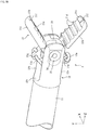
Fig. 2A is a perspective view illustrating a configuration in the vicinity of an electrode of the forceps type treatment instrument illustrated inFig. 1 ; -
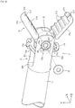
Fig. 2B is a perspective view illustrating the configuration in the vicinity of the electrode of the forceps type treatment instrument illustrated inFig. 1 when viewed from a different angle; -
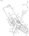
Fig. 2C is an exploded perspective view of a kingpin in the vicinity of the electrode illustrated inFig. 2A ; -
Fig. 2D is an exploded perspective view of a washer in the vicinity of the electrode illustrated inFig. 2B ; -
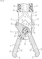
Fig. 3A is a longitudinal sectional view illustrating a configuration of a second forceps piece of the forceps type treatment instrument illustrated inFig. 1 ; -
Fig. 3B is a longitudinal sectional view illustrating a configuration of a first forceps piece of the forceps type treatment instrument illustrated inFig. 1 ; -
Fig. 4A is a perspective view illustrating a configuration of an insulation spacer of the forceps type treatment instrument illustrated inFig. 1 ; -
Fig. 4B is a right side view of the insulation spacer illustrated inFig. 4A ; -
Fig. 4C is a front view of the insulation spacer illustrated inFig. 4A ; -
Fig. 4D is a left side view of the insulation spacer illustrated inFig. 4A ; -
Fig. 5A is a perspective view illustrating a configuration in the vicinity of an electrode of a forceps type treatment instrument of a second embodiment of the present invention and is an exploded view of a kingpin; -
Fig. 5B is a plan view illustrating a configuration in the vicinity of the electrode without the kingpin illustrated inFig. 5A ; -
Fig. 5C is a perspective view illustrating the configuration in the vicinity of the electrode of the forceps type treatment instrument illustrated inFig. 5A when viewed from a different angle and is an exploded view of a washer in the vicinity of the electrode; -
Fig. 6A is a longitudinal sectional view illustrating a configuration of a second forceps piece of the forceps type treatment instrument illustrated inFig. 5A ; -
Fig. 6B is a longitudinal sectional view illustrating a configuration of a first forceps piece of the forceps type treatment instrument illustrated inFig. 5A ; -
Fig. 7A is a perspective view illustrating a configuration of an insulation spacer of the forceps type treatment instrument illustrated inFig. 5A ; -
Fig. 7B is a right side view of the insulation spacer illustrated inFig. 7A ; -
Fig. 7C is a front view of the insulation spacer illustrated inFig. 7A ; -
Fig. 7D is a left side view of the insulation spacer illustrated inFig. 7A ; -
Figs. 8(A) to 8(D) are diagrams illustrating a modified example of the forceps type treatment instrument of the second embodiment; -
Fig. 9A is a partially exploded perspective view illustrating a configuration in the vicinity of an electrode of a forceps type treatment instrument of a third embodiment of the present invention; -
Fig. 9B is a partially exploded perspective view illustrating the vicinity of the electrode of the forceps type treatment instrument illustrated inFig. 9A when viewed from a different angle; -
Fig. 10A is a perspective view illustrating a configuration of an insulation spacer illustrated inFigs. 9A and9B ; and -
Fig. 10B is a right side view of the insulation spacer illustrated inFig. 10A . - Hereinafter, a bipolar hemostat as a forceps type treatment instrument according to a first embodiment of the present invention will be described in detail with reference to
Figs. 1 ,2A to 2D ,3A ,3B , and4A to 4D . However, the present invention is not limited to the bipolar hemostat and can be also applied to a bipolar knife or the like including forceps pieces corresponding to a pair of openable and closable electrodes and a forceps type treatment instrument including forceps pieces not functioning as electrodes. - As illustrated in
Fig. 1 , the bipolar hemostat of the present embodiment schematically includes asheath part 1, anoperation part 2, and atreatment part 3. Theoperation part 2 is provided at a proximal end of thesheath part 1 and thetreatment part 3 is provided at a distal end of thesheath part 1. - The
operation part 2 includes abase 21 and aslider 22 which is attached to the base 21 in a slidable manner, thetreatment part 3 includes aforceps portion 31 with a pair of electrodes (a first forceps piece and a second forceps piece) 31a and 31b provided to be openable and closable, and theforceps portion 31 can be opened and closed and rotated by the operation of theoperation part 2. - The
operation part 2 includes a pair of electric wires (cables) 24a and 24b and plugs 24 respectively provided at base end portions thereof and theelectric wires plugs 24 so that a high-frequency current is supplied thereto. Theelectric wire 24a is electrically connected to thefirst forceps piece 31a and theelectric wire 24b is electrically connected to thesecond forceps piece 31b. - The
sheath part 1 includes a tubularouter sheath 11, a tubular inner sheath (not illustrated), and adrive wire 13. Theouter sheath 11 is formed as a flexible hollow tube and a tube which is formed of insulation resin is used. In the same way, the inner sheath is formed as a flexible hollow tube and a tube which is formed of insulation resin is used. A resin material of forming theouter sheath 11 and the inner sheath is not particularly limited as long as the insulation material is used and polyethylene, polypropylene, polyvinyl chloride, polyurethane, polyamide, polyester, polycarbonate, polyether sulfone, fluororesin and the like can be used. - The
drive wire 13 is inserted through the inner sheath and the inner sheath is inserted through theouter sheath 11. Thedrive wire 13 is rotatable about the axis and is slidable (slidable along the axial direction) inside the inner sheath. - The
drive wire 13 is formed as two flexible and conductive wires and the surfaces of two wires are respectively coated with an insulation coating to be insulated from each other. - The
drive wire 13 is a power transmission member that transmits a sliding force for opening and closing theforceps portion 31 and a rotating force for rotating theforceps portion 31 about a sheath axis to adjust the posture thereof. - The
operation part 2 schematically includes abase 21, aslider 22, and anend cap 23. Thebase 21 includes aring portion 21a and aguide portion 21b with a guide groove. Theslider 22 is attached to be slidable along theguide portion 21b of the base 21 in the front and rear direction (the left and right direction ofFig. 1 ). Theend cap 23 is attached to a front end (distal end) of thebase 21. Thebase 21, theslider 22, and theend cap 23 are mainly formed of insulation resin. - The
end cap 23 includes an approximately cylindrical space at the inside of the front end portion thereof and a proximal end of thesheath part 1 including theouter sheath 11, the inner sheath (not illustrated), and thedrive wire 13 is inserted thereinto through a penetration portion formed at a front end of theend cap 23. - The
drive wire 13 can be slid inside thesheath part 1 in the axial direction when theslider 22 of theoperation part 2 is slid with respect to the base 21 in the front and rear direction (the left and right direction ofFig. 1 ) and thedrive wire 13 can be rotated about the axis inside thesheath part 1 when theoperation part 2 is rotated with respect to the sheath part 1 (the outer sheath 11) . - The
treatment part 3 schematically includes, as illustrated inFigs. 2A to 2D ,3A , and3B , theforceps portion 31 including thefirst forceps piece 31a and thesecond forceps piece 31b corresponding to a pair of electrodes, a resin frame (forceps support member) 32, an insulation spacer (spacer member) 33, and the like. Theresin frame 32 includes abase end portion 32c which includes an approximatelycylindrical head portion 32d (seeFigs. 3A and3B ) and a pair of arm portions (a first arm portion and a second arm portion) 32a and 32b which protrudes from thebase end portion 32c in the Z-axis direction and faces each other in the X-axis direction. Note that, in the drawings, the X axis, the Y axis, and the Z axis are perpendicular to one another. - As illustrated in
Figs. 2C and2D , an approximately circularconcave portion 32f is formed in the vicinity of the front end portions of thefirst arm portion 32a and thesecond arm portion 32b from the outside (non-opposing side). A fitting hole (first fitting hole) 32e is formed in theconcave portion 32f of thefirst arm portion 32a to penetrate the inside and the outside thereof (seeFig. 2D ). A fitting hole (second fitting hole) 32e is formed in theconcave portion 32f of thesecond arm portion 32b to penetrate the inside and the outside thereof (seeFig. 2C ). Thehead portion 32d of theresin frame 32 is rotatably attached to the distal end of theouter sheath 11 through a rotation support member (not illustrated) including a fixedmember 11a (seeFigs. 3A and3B ) provided at the distal end portion of theouter sheath 11. - The
base end portion 32c and thehead portion 32d of theresin frame 32 are provided with a through-hole 32i and afirst wire member 17a and asecond wire member 17b which are formed of conductive steel wires and are coated with an insulation coating are disposed to pass through the through-holes 32i. Although not illustrated in the drawings, the proximal ends of thefirst wire member 17a and thesecond wire member 17b are respectively fixed to the distal ends of two wires constituting thedrive wire 13, the distal end of thefirst wire member 17a is connected to a through-hole 31g of thefirst forceps piece 31a, and the distal end of thesecond wire member 17b is connected to the through-hole 31g of thesecond forceps piece 31b. - In accordance with the sliding of the
drive wire 13, the sliding force is transmitted to thefirst forceps piece 31a and thesecond forceps piece 31b through thefirst wire member 17a and thesecond wire member 17b so that thefirst forceps piece 31a and thesecond forceps piece 31b can be opened and closed. Thefirst forceps piece 31a and thesecond forceps piece 31b which are located at the opposite sides in the Y-axis direction rotate about the rotation shaft (kingpin 34) following the X axis to move close to theinsulation spacer 33 and theforceps portion 31 is closed so that an affected part to be treated can be clamped between the grip portions of the forceps pieces. At the time of opening theforceps portion 31, a reverse operation may be performed. - Note that, the proximal end of the
first wire member 17a is fixed to thedrive wire 13 while being electrically connected to one of two wires constituting thedrive wire 13, so that thefirst forceps piece 31a is electrically connected to theelectric wire 24a (seeFig. 1 ) through thefirst wire member 17a and thedrive wire 13. Further, the proximal end of thesecond wire member 17b is fixed to thedrive wire 13 while being electrically connected to the other of two wires constituting thedrive wire 13. Therefore, thesecond forceps piece 31b is electrically connected to theelectric wire 24b (seeFig. 1 ) through thesecond wire member 17b and thedrive wire 13. - The
fitting holes arm portions shaft portions insulation spacer 33 described later are fittable thereto. - The
first forceps piece 31a and thesecond forceps piece 31b constituting theforceps portion 31 are rotatably supported while being electrically insulated by the insulation spacer (spacer member) 33 formed of insulation resin (for example, polycarbonate) to have a roughly X-shape and are disposed between thefirst arm portion 32a and thesecond arm portion 32b of theresin frame 32 in this state. - The grip portions on the front end sides of the
first forceps piece 31a and thesecond forceps piece 31b are provided with a plurality of (in this example, four)mountain teeth 31d which extend in a direction (hereinafter, referred to as a lateral direction) following the rotation shaft (X axis) of each of thefirst forceps piece 31a and thesecond forceps piece 31b in parallel to a direction (hereinafter, referred to as the longitudinal direction) approximately orthogonal to the lateral direction and is also provided with a front endconvex tooth 31e. A center portion of the front endconvex tooth 31e is provided with a single front endlongitudinal groove 31f in the longitudinal direction. - In the
first forceps piece 31a and thesecond forceps piece 31b, as illustrated inFigs. 3A and3B , an intermediate portion thereof is provided with a shaft hole (a first shaft hole, a second shaft hole) 31c having an approximately circular cross-section and a rear end thereof is provided with a through-hole 31g to which thefirst wire member 17a or thesecond wire member 17b is attached. - A part of the inner peripheral surface of the
shaft hole 31c of thefirst forceps piece 31a is provided with a notch portion (first notch portion) 31h which is widened from the axis center outward in the radial direction. Thenotch portion 31h is provided with an end portion (first end portion) 31i with which a protrusion portion (first protrusion portion) 33f formed in theshaft portion 33a of theinsulation spacer 33 comes into contact when thefirst forceps piece 31a rotates in a first direction (a direction in which the grip portion of thefirst forceps piece 31a moves close to the grip portion of thesecond forceps piece 31b, a counter-clockwise direction inFig. 3B ). Further, thenotch portion 31h is provided with an end portion (second end portion) 31j with which the protrusion portion (first protrusion portion) 33f formed in theshaft portion 33a of theinsulation spacer 33 comes into contact when thefirst forceps piece 31a rotates in a second direction opposite to the first direction (a direction in which the grip portion of thefirst forceps piece 31a moves away from the grip portion of thesecond forceps piece 31b, a clockwise direction inFig. 3B ) and the end portion (second end portion) 31j is provided as the other end facing thefirst end portion 31i in thenotch portion 31h. A circumferential distance space of thenotch portion 31h from thefirst end portion 31i to thesecond end portion 31j defines the rotation range of thefirst forceps piece 31a. Note that, in the present embodiment, when thefirst forceps piece 31a is opened by an angle of 55° with respect to the center axis of theouter sheath 11 as viewed from the rotation axis direction of thefirst forceps piece 31a, theprotrusion portion 33f comes into contact with thesecond end portion 31j. Further, when thefirst forceps piece 31a becomes horizontal with respect to the center axis of theouter sheath 11, theprotrusion portion 33f comes into contact with thefirst end portion 31i. - The inner peripheral surface of the
shaft hole 31c of thesecond forceps piece 31b is provided with the notch portion (second notch portion) 31h which is widened from the axis center outward in the radial direction. Thenotch portion 31h is provided with the end portion (the third end portion) 31i with which the protrusion portion (second protrusion portion) 33f formed in theshaft portion 33b of theinsulation spacer 33 comes into contact when thesecond forceps piece 31b rotates in the second direction (a direction in which the grip portion of thesecond forceps piece 31b moves close to the grip portion of thefirst forceps piece 31a, a clockwise direction inFig. 3A ). Further, thenotch portion 31h is provided with the end portion (fourth end portion) 31j with which the protrusion portion (second protrusion portion) 33f formed in theshaft portion 33b of theinsulation spacer 33 comes into contact when thesecond forceps piece 31b rotates in the first direction opposite to the second direction (a direction in which the grip portion of thesecond forceps piece 31b moves away from the grip portion of thefirst forceps piece 31a, a counter-clockwise direction inFig. 3A ) and the end portion (second end portion) 31j is provided as the other end facing thethird end portion 31i of thenotch portion 31h. A circumferential distance space of thenotch portion 31h from thethird end portion 31i to thefourth end portion 31j defines the rotation range of thesecond forceps piece 31b. Note that, in the present embodiment, when thesecond forceps piece 31b is opened by an angle of 55° with respect to the center axis of theouter sheath 11 as viewed from the rotation axis direction of thesecond forceps piece 31b, theprotrusion portion 33f comes into contact with thefourth end portion 31j. Further, when thesecond forceps piece 31a becomes horizontal with respect to the center axis of theouter sheath 11, theprotrusion portion 33f comes into contact with thethird end portion 31i. Further, the pair ofprotrusion portions 33f protrudes outward in the radial direction of the rotation shaft (X axis) of theshaft portion 33a and is formed at the same circumferential position of theshaft portion 33a in the present embodiment. However, the pair of protrusions may not be formed at the same position. - The
insulation spacer 33 is, as illustrated inFigs. 4A to 4D , a member that rotates (turns) thefirst forceps piece 31a and thesecond forceps piece 31b while axially supporting them in an electrically insulated state. Theinsulation spacer 33 mainly includes an approximately plate-shapedspacer portion 33c, an approximatelycylindrical shaft portion 33a which protrudes toward one surface of thespacer portion 33c, and an approximatelycylindrical shaft portion 33b which protrudes toward the other surface of thespacer portion 33c. Theshaft portion 33a and theshaft portion 33b are symmetrical to each other and are coaxially disposed. Through-holes 33d at the center portions of theshaft portion 33a and theshaft portion 33b communicate with each other to penetrate thespacer portion 33c. - The outer diameter of the
shaft portion 33a is set to a value slightly smaller than the inner diameter of theshaft hole 31c of thefirst forceps piece 31a so as to be rotatably inserted into theshaft hole 31c of thefirst forceps piece 31a. The dimension (height) of the axial direction of each of theshaft portions shaft portion 33a is fitted to thefitting hole 32e of thearm portion 32a of theresin frame 32 and the front end portion of theshaft portion 33b is fitted to thefitting hole 32e of thearm portion 32b of theresin frame 32. - Further, the
shaft portion 33a of the present embodiment includes theprotrusion portion 33f which protrudes outward in the radial direction in the cross-section orthogonal to the axis of theshaft portion 33a. Theprotrusion portion 33f is formed to be movably disposed inside thenotch portion 31h formed in theshaft hole 31c when theshaft portion 33a is inserted into theshaft hole 31c of thefirst forceps piece 31a. The dimension (height) of the axial direction of theprotrusion portion 33f is set so that the protrusion portion comes into contact with the inner surface of thearm portion 32a when the front end portion of theshaft portion 33a is fitted to thefitting hole 32e of thearm portion 32a of theresin frame 32 and the front end portion of theshaft portion 33b is fitted to thefitting hole 32e of thearm portion 32b of theresin frame 32. That is, theprotrusion portion 33f is set to a height in which the protrusion portion does not reach thefitting hole 32e. - Since the
shaft portion 33b has substantially the same configuration as that of theshaft portion 33a except that the shaft portion is disposed to be plane-symmetrical to the above-describedshaft portion 33a, a description thereof will be omitted. - Note that, in the present embodiment, the
protrusion portion 33f is integrally formed with theshaft portions spacer portion 33c to the front end coming into contact with the inner surfaces of thearm portions shaft portions spacer portion 33c and also may not come into contact with the inner surfaces of thearm portions protrusion portion 33f is integrally formed along theshaft portions protrusion portion 33f is reinforced by theshaft portions protrusion portion 33f may protrude from thespacer portion 33c to be independent from theshaft portions shaft portions protrusion portion 33f and theshaft portions - The
spacer portion 33c is integrally provided with asupport protrusion 33g which protrudes toward one surface thereof and asupport protrusion 33g which protrudes toward the other surface thereof. The dimension (height) of the axial direction of thesupport protrusion 33g is set so that the support protrusion comes into contact with the inner surfaces of thearm portions shaft portion 33a is fitted to thefitting hole 32e of thearm portion 32a of theresin frame 32 and the front end portion of theshaft portion 33b is fitted to thefitting hole 32e of thearm portion 32b of theresin frame 32. That is, the dimension is set to be the same as the dimension of the axial direction of theprotrusion portion 33f. The support protrusions 33g and 33g are used to define a gap between the pair ofarm portions resin frame 32 and are provided at a position in which the rotation of the correspondingforceps pieces spacer portion 33c. - The
first forceps piece 31a is axially supported by theinsulation spacer 33 to be rotatable while theshaft portion 33a of theinsulation spacer 33 is inserted into theshaft hole 31c and thesecond forceps piece 31b is axially supported by theinsulation spacer 33 to be rotatable while theshaft portion 33b of theinsulation spacer 33 is inserted into theshaft hole 31c. In this state, the front end portion of theshaft portion 33a of theinsulation spacer 33 is fitted to thefitting hole 32e of thearm portion 32a and the front end portion of theshaft portion 33b of theinsulation spacer 33 is fitted to thefitting hole 32e of thearm portion 32b while the pair ofarm portions resin frame 32 is slightly elastically deformed outward. Next, as illustrated inFig. 2C , thekingpin 34 is inserted through the center through-holes 33d of theshaft portions insulation spacer 33 and awasher 35 is fitted and fixed to the front end of thekingpin 34 from the opposite side as illustrated inFig. 2D . Accordingly, as illustrated inFig. 2A or2B , thefirst forceps piece 31a and thesecond forceps piece 31b which are axially supported by theinsulation spacer 33 to be rotatable are supported between the pair ofarm portions - According to the present embodiment, the opening and closing angle ranges of the
first forceps piece 31a and thesecond forceps piece 31b are defined by theend portions notch portion 31h formed in theshaft hole 31c of thefirst forceps piece 31a and theprotrusion portion 33f formed in theshaft portion 33a of theinsulation spacer 33. Further, the opening and closing angle range of thesecond forceps piece 31b is defined by theend portions notch portion 31h formed in theshaft hole 31c of thesecond forceps piece 31b and theprotrusion portion 33f formed in theshaft portion 33b of theinsulation spacer 33. When the opening and closing angles in a direction in which thefirst forceps piece 31a and thesecond forceps piece 31b are opened are defined, it is possible to solve a problem in which theforceps pieces forceps pieces forceps pieces forceps pieces outer sheath 11, it is possible to prevent a problem in which oneforceps piece 31a (31b) press-inserts theother forceps piece 31b (31a) so that theforceps portion 31 moves in a swinging manner and hence to stabilize the movement of theforceps portion 31 when theforceps portion 31 is pressed into the lumen or the like of the endoscope. In the related art, the opening and closing angle range of the forceps piece is defined in such a manner that a circular-arc groove is formed in a side surface of a spacer portion of an insulation spacer and a protrusion portion is provided in a side surface of an electrode to be loosely fitted to the groove. However, in the related art, only a relatively small protrusion portion can be formed in structure and strength cannot be sufficiently ensured. - In contrast, according to the structure of the present embodiment, it is possible to form the
protrusion portion 33f to be relatively large outward in the radial direction and to secure sufficient strength. Further, in the related art, there is a case in which a protrusion portion is separated from a groove (the protrusion portions gets on a portion other than the groove), but such a problem can be prevented. Further, for example, when cutting is used to form the protrusion on the side surface (plane) of the forceps piece, there is a need to cut the other portion while remaining the protrusion portion. Accordingly, much effort and cost are necessary for the processing, but in the structure of the present embodiment, theprotrusion portion 33f can be integrally molded with theinsulation spacer 33 by, for example, resin molding. As a result, effort and cost for the processing can be reduced. - Note that, in the above-described first embodiment, the
protrusion portion 33f is formed so that theprotrusion portion 33f comes into contact with bothend portions notch portion 31h in response to the rotation of theforceps pieces forceps pieces protrusion portion 33f and thenotch portion 31h only in any one of opening and closing direction and the opening and closing angle may not be defined or may be defined by other members in the other opening and closing angle. - Further, in the above-described first embodiment, the
protrusion portion 33f is formed in a part of the outer peripheral surfaces of theshaft portions notch portion 31h is formed in a part of the inner peripheral surface of theshaft hole 31c, but these components may be provided at the opposite positions. For example, thenotch portion 31h may be formed in a part of the outer peripheral surfaces of theshaft portions protrusion portion 33f may be formed in a part of the inner peripheral surface of theshaft hole 31c. - Hereinafter, a bipolar hemostat as a forceps type treatment instrument according to a second embodiment of the present invention will be described in detail with reference to
Figs. 5A to 5C ,6A ,6B , and7A to 7D . The same numerals will be given to the components having substantially the same configurations as those of the above-described first embodiment, a part of a description thereof will be omitted, and a difference will be mainly described. - In the above-described first embodiment, the shape (cross-sectional shape) of each of the
fitting holes arm portions resin frame 32 was an approximately circular shape. In contrast, in the second embodiment, as illustrated inFigs. 5A to 5C , the shape (cross-sectional shape) of each offitting holes 32e' and 32e' of thearm portions resin frame 32 is a roughly oval shape (a shape obtained by cutting a circle with a pair of centrosymmetric parallel lines) provided with thecomplementary portions shaft portions 33a' and 33b' of theinsulation spacer 33 described later are fittable. - The
shaft portion 33a' of theinsulation spacer 33 is formed as illustrated inFigs. 6A ,6B , and7A to 7D and the outer diameter thereof is set to a value slightly smaller than the inner diameter of theshaft hole 31c of thefirst forceps piece 31a so as to be rotatably inserted into theshaft hole 31c of thefirst forceps piece 31a. Theshaft portion 33a' is provided with a pair ofcutout portions cutout portions shaft portion 33a'. In the present embodiment, the plane forming onecutout portion 33e and the plane forming theother cutout portion 33e are set to be approximately parallel to each other. Thus, the cross-sectional shape of theshaft portion 33a' is a roughly oval shape (a shape obtained by cutting a circle with a pair of centrosymmetric parallel lines). However, planes forming thecutout portions shaft portion 33a'. - Since the
shaft portion 33b' has substantially the same configuration as that of theshaft portion 33a' except that the shaft portion is plane-symmetrical to the above-describedshaft portion 33a', a description thereof will be omitted. - In a state in which the front end portion of the
shaft portion 33a' of theinsulation spacer 33 is fitted to thefitting hole 32e' of thearm portion 32a of theresin frame 32 and the front end portion of theshaft portion 33b' of theinsulation spacer 33 is fitted to thefitting hole 32e' of thearm portion 32b of theresin frame 32, thecutout portion 33e of each of theshaft portions 33a' and 33b' and thecomplementary portion 32g of thefitting hole 32e' of each of thearm portions insulation spacer 33 with respect to theresin frame 32 is reliably prevented, it is possible to prevent a change in positional relationship between theresin frame 32 and theinsulation spacer 33 regardless of the operation of opening and closing thefirst forceps piece 31a and thesecond forceps piece 31b and thus to stabilize the postures of thefirst forceps piece 31a and thesecond forceps piece 31b. - That is, when the
insulation spacer 33 rotates with respect to theresin frame 32, there is concern that the direction of the distal end of theforceps portion 31 including the pair offorceps pieces insulation spacer 33 to be opened and closed may be inclined with respect to theresin frame 32. In the forceps type treatment instrument of the second embodiment, since it is possible to reduce such concern, it is possible to provide the forceps type treatment instrument having excellent operability. - Next, a modified example of the complementary portion and the cutout portion for preventing the rotation of the
insulation spacer 33 with respect to theresin frame 32 in the above-described second embodiment will be described with reference toFig. 8 . Further, the same numerals will be given to the components substantially having the same configurations as those of the above-described second embodiment and only a difference will be described. - In the above-described second embodiment, the pair of
cutout portions 33e of each of theshaft portions 33a' and 33b' of theinsulation spacer 33 is formed and the pair ofcomplementary portions 32g of each of thefitting holes 32e' of thearm portions resin frame 32 is formed to correspond to those components. However, the number of thecutout portions 33e and thecomplementary portions 32g is not limited to a pair (two), but may be single (one) as illustrated inFig. 8(A) , three as illustrated inFig. 8(B) , four as illustrated inFig. 8(C) , or four or more. - Further, as illustrated in
Fig. 8(D) , aconcave cutout portion 33k of each ofshaft portions 33a' and 33b' of theinsulation spacer 33 may be formed and a convexcomplementary portion 32k having a shape of complementing thecutout portion 33k may be formed in thefitting hole 32e of each of thearm portions resin frame 32 so as to correspond to those components. In this case, the shapes of thecutout portion 33k and thecomplementary portion 32k may be circular-arc shapes as illustrated inFig. 8(D) or may be rectangular shapes or other shapes. The number of thecutout portions 33k and thecomplementary portions 32k may be also two or more. - Further, in the above-described second embodiment, the
cutout portion 33e is provided at both of theshaft portion 33a'and 33b' of theinsulation spacer 33, but may be provided only at one of them. In this case, thecomplementary portion 32g may be provided only at a portion corresponding to thefitting hole 32e' of each of thearm portions resin frame 32. - Further, in the above-described second embodiment, the
cutout portion 33e is provided across the entire portion (a portion from a base end near thespacer portion 33c to a front end) in the axial direction of theshaft portions 33a' and 33b' of theinsulation spacer 33, but thecutout portion 33e may be provided only at the front end portion to be fitted to thefitting hole 32e' of each of thearm portions - Next, a bipolar hemostat as a forceps type treatment instrument according to a third embodiment of the present invention will be described with reference to
Figs. 9A ,9B ,10A, and 10B . The same numerals will be given to the components having substantially the same configurations as those of the above-described first embodiment and a difference will be described. - In the above-described first embodiment, as illustrated in
Figs. 4A and 4B , the dimension (height) of the axial direction of each of theprotrusion portions 33f of theshaft portions insulation spacer 33 is set to be smaller (lower) than the dimension (height) of the axial direction of each of theshaft portions insulation spacer 33 to have a step therebetween. In the third embodiment, as illustrated inFigs. 10A and 10B , the dimension (height) of the axial direction of each ofprotrusion portions 33f' ofshaft portions 33a" and 33b" of theinsulation spacer 33 is set to be the same as the dimension (height) of the axial direction of each of theshaft portions 33a" and 33b" of theinsulation spacer 33. Further, as illustrated inFigs. 9A and9B , theconcave cutout portion 32h which is complemented by thefront end portion 33h of theprotrusion portion 33f' when the front end portions (the complementary portions) 33h of theprotrusion portions 33f' are fitted to thefitting holes 32e" of thearm portions resin frame 32 is formed in a part of the inner peripheral surface of thefitting hole 32e". - In a state in which the front end portion of the
shaft portion 33a" of theinsulation spacer 33 is fitted to thefitting hole 32e" of thearm portion 32a of theresin frame 32 and the front end portion of theshaft portion 33b" of theinsulation spacer 33 is fitted to thefitting hole 32e" of thearm portion 32b of theresin frame 32, the front end portion (the complementary portion) 33h of theprotrusion portion 33f' and thecutout portion 32h of thefitting hole 32e" of each of thearm portions insulation spacer 33 with respect to theresin frame 32 is reliably prevented, it is possible to prevent a change in positional relationship between theresin frame 32 and theinsulation spacer 33 regardless of the operation of opening and closing thefirst forceps piece 31a and thesecond forceps piece 31b and thus to stabilize the postures of thefirst forceps piece 31a and thesecond forceps piece 31b. - That is, when the
insulation spacer 33 rotates with respect to theresin frame 32, there is concern that the direction of the distal end of theforceps portion 31 including the pair offorceps pieces insulation spacer 33 to be opened and closed may be inclined with respect to theresin frame 32. In the forceps type treatment instrument of the third embodiment, since it is possible to reduce such concern, it is possible to provide the forceps type treatment instrument having excellent operability. - In the third embodiment, since the
front end portions 33h of theprotrusion portions 33f' of theshaft portions 33a" and 33b" of theinsulation spacer 33 for defining the opening and closing angles of the pair offorceps pieces cutout portions 32h formed in thefitting holes 32e" of thearm portions resin frame 32, it is possible to realize the same function as that of the second embodiment which prevents a change in posture (rotation) of theinsulation spacer 33 with respect to theresin frame 32 in addition to a function of defining the opening and closing angles of theforceps pieces - The embodiments above are described to help the understanding of the present invention and are not described to limit the present invention. Therefore, each component disclosed in the embodiments above is intended to include all design changes and equivalents belonging to the technical scope of the present invention.
-
- 1 SHEATH PART
- 11 OUTER SHEATH
- 13 DRIVE WIRE
- 17a, 17b WIRE MEMBER
- 2 OPERATION PART
- 21 BASE
- 22 SLIDER
- 23 END CAP
- 24 PLUG
24a, 24b ELECTRIC WIRE - 3 TREATMENT PART
- 31 FORCEPS PORTION
- 31a, 31b ELECTRODE (FIRST FORCEPS PIECE, SECOND FORCEPS PIECE)
- 31c SHAFT HOLE (FIRST SHAFT HOLE, SECOND SHAFT HOLE)
- 31h NOTCH PORTION
- 31i END PORTION (FIRST END PORTION, THIRD END PORTION)
- 31j END PORTION (SECOND END PORTION, FOURTH END PORTION)
- 32 RESIN FRAME (FORCEPS SUPPORT MEMBER)
- 32a, 32b ARM PORTION (FIRST ARM PORTION, SECOND ARM PORTION)
- 32c BASE END PORTION
- 32e, 32e', 32e" FITTING HOLE (FIRST FITTING HOLE, SECOND FITTING HOLE)
- 32h CUTOUT PORTION
- 33 INSULATION SPACER
- 33a, 33b, 33a', 33b', 33a", 33b" SHAFT PORTION (FIRST SHAFT PORTION, SECOND SHAFT PORTION)
- 33c SPACER PORTION
- 33d THROUGH-HOLE
- 33f, 33f' PROTRUSION PORTION
- 33g SUPPORT PROTRUSION
- 33h FRONT END PORTION OF PROTRUSION PORTION (COMPLEMENTARY PORTION)
- 31 FORCEPS PORTION
Claims (8)
- A forceps type treatment instrument comprising:a forceps support member that includes a first arm portion and a second arm portion attached to a distal end of a sheath and facing each other;a first forceps piece and a second forceps piece which are interposed between the first arm portion and the second arm portion of the forceps support member; anda spacer member that rotatably supports each of the first forceps piece and the second forceps piece,wherein the first forceps piece includes a first shaft hole,wherein the second forceps piece includes a second shaft hole,wherein the spacer member includes a first shaft portion rotatably inserted into the first shaft hole and a second shaft portion rotatably inserted into the second shaft hole,wherein the spacer member is provided with a first protrusion portion and a second protrusion portion,wherein an inner peripheral surface of the first shaft hole is provided with a first notch portion,wherein an inner peripheral surface of the second shaft hole is provided with a second notch portion,wherein the first notch portion is provided with a first end portion with which the first protrusion portion comes into contact when the first forceps piece is rotated in a first direction and a second end portion which is the other end facing the first end portion, andwherein the second notch portion is provided with a third end portion with which the second protrusion portion comes into contact when the second forceps piece is rotated in a second direction opposite to the first direction and a fourth end portion which is the other end facing the third end portion.
- The forceps type treatment instrument according to claim 1,
wherein the first protrusion portion comes into contact with the second end portion when the first forceps piece is rotated in the second direction, and
wherein the second protrusion portion comes into contact with the fourth end portion when the second forceps piece is rotated in the first direction. - The forceps type treatment instrument according to claim 1 or 2,
wherein the first protrusion portion is provided so as to protrude from an outer surface of the first shaft portion, and
wherein the second protrusion portion is provided so as to protrude from an outer surface of the second shaft portion. - A forceps type treatment instrument comprising:a forceps support member that includes a first arm portion and a second arm portion attached to a distal end of a sheath and facing each other;a first forceps piece and a second forceps piece which are interposed between the first arm portion and the second arm portion of the forceps support member; anda spacer member that rotatably supports each of the first forceps piece and the second forceps piece,wherein the first forceps piece includes a first shaft hole,wherein the second forceps piece includes a second shaft hole,wherein the spacer member includes a first shaft portion rotatably inserted into the first shaft hole and a second shaft portion rotatably inserted into the second shaft hole,wherein the first arm portion includes a first fitting hole into which a front end portion of the first shaft portion is fitted,wherein the second arm portion includes a second fitting hole into which a front end portion of the second shaft portion is fitted,wherein a cutout portion is provided in at least one of the first fitting hole and the front end portion of the first shaft portion, andwherein a complementary portion which complements the cutout portion is provided in at least the other one of the first fitting hole and the front end portion of the first shaft portion.
- The forceps type treatment instrument according to claim 4,
wherein a cutout portion is provided in at least one of the second fitting hole and the front end portion of the second shaft portion, and
wherein a complementary portion which complements the cutout portion is provided in at least the other one of the second fitting hole and the front end portion of the second shaft portion. - The forceps type treatment instrument according to claim 4 or 5,
wherein a cross-sectional shape orthogonal to an axis of at least the first fitting hole and the front end portion of the first shaft portion is a shape in which at least a part of a circular shape is cutting out. - The forceps type treatment instrument according to any one of claims 4 to 6,
wherein an outer peripheral surface of the first shaft portion is provided with a first protrusion portion,
wherein an inner peripheral surface of the first shaft hole is provided with a first notch portion,
wherein an outer peripheral surface of the second shaft portion is provided with a second protrusion portion,
wherein an inner peripheral surface of the second shaft hole is provided with a second notch portion,
wherein the first notch portion is provided with a first end portion with which the first protrusion portion comes into contact when the first forceps piece rotates in a first direction and a second end portion into which the first protrusion portion comes into contact when the first forceps piece rotates in a second direction opposite to the first direction, and
wherein the second notch portion is provided with a third end portion into which the second protrusion portion comes into contact when the second forceps piece rotates in the second direction and a fourth end portion into which the second protrusion portion comes into contact when the second forceps piece rotates in the first direction. - The forceps type treatment instrument according to any one of claims 4 to 6,
wherein an inner peripheral surface of the first shaft hole is provided with a first protrusion portion,
wherein an outer peripheral surface of the first shaft portion is provided with a first notch portion,
wherein an inner peripheral surface of the second shaft hole is provided with a second protrusion portion,
wherein an outer peripheral surface of the second shaft portion is provided with a second notch portion,
wherein the first notch portion is provided with a first end portion with which the first protrusion portion comes into contact when the first forceps piece rotates in a first direction and a second end portion into which the first protrusion portion comes into contact when the first forceps piece rotates in a second direction opposite to the first direction, and
wherein the second notch portion is provided with a third end portion into which the second protrusion portion comes into contact when the second forceps piece rotates in the second direction and a fourth end portion into which the second protrusion portion comes into contact when the second forceps piece rotates in the first direction.
Applications Claiming Priority (3)
| Application Number | Priority Date | Filing Date | Title |
|---|---|---|---|
| JP2016071600 | 2016-03-31 | ||
| JP2016071556 | 2016-03-31 | ||
| PCT/JP2017/012936 WO2017170711A1 (en) | 2016-03-31 | 2017-03-29 | Forceps-type treatment instrument |
Publications (3)
| Publication Number | Publication Date |
|---|---|
| EP3437580A1 true EP3437580A1 (en) | 2019-02-06 |
| EP3437580A4 EP3437580A4 (en) | 2019-11-13 |
| EP3437580B1 EP3437580B1 (en) | 2023-05-03 |
Family
ID=59965679
Family Applications (1)
| Application Number | Title | Priority Date | Filing Date |
|---|---|---|---|
| EP17775245.8A Active EP3437580B1 (en) | 2016-03-31 | 2017-03-29 | Forceps-type treatment instrument |
Country Status (4)
| Country | Link |
|---|---|
| EP (1) | EP3437580B1 (en) |
| JP (1) | JP6897670B2 (en) |
| CN (1) | CN108697460B (en) |
| WO (1) | WO2017170711A1 (en) |
Families Citing this family (5)
| Publication number | Priority date | Publication date | Assignee | Title |
|---|---|---|---|---|
| JP7286068B2 (en) * | 2019-03-29 | 2023-06-05 | 日本ゼオン株式会社 | Endoscope Microwave Irradiator |
| CN113662596A (en) * | 2020-05-14 | 2021-11-19 | 西安交通大学医学院第一附属医院 | Tissue Clip Assemblies and Clamps |
| CN112315576A (en) * | 2020-11-02 | 2021-02-05 | 山东威高手术机器人有限公司 | Bipolar electric energy forceps head for minimally invasive surgical instrument |
| CN117357192A (en) * | 2022-06-30 | 2024-01-09 | 北京迈迪顶峰医疗科技股份有限公司 | Conveying actuators and conveying devices |
| JPWO2024253184A1 (en) * | 2023-06-09 | 2024-12-12 |
Family Cites Families (8)
| Publication number | Priority date | Publication date | Assignee | Title |
|---|---|---|---|---|
| JP2001259263A (en) * | 2000-03-23 | 2001-09-25 | Yaoki Kogyo Kk | Scissors |
| EP2263586B1 (en) * | 2001-04-06 | 2018-06-06 | Covidien AG | Vessel sealer and divider |
| JP3934458B2 (en) * | 2002-04-09 | 2007-06-20 | ペンタックス株式会社 | Bipolar high-frequency hemostatic forceps for endoscope |
| WO2006119139A2 (en) * | 2005-04-29 | 2006-11-09 | Bovie Medical Corporation | Forceps for performing endoscopic or arthrocsopic surgery |
| DE202007009165U1 (en) * | 2007-06-29 | 2007-08-30 | Kls Martin Gmbh + Co. Kg | Surgical instrument |
| CN201529148U (en) * | 2009-09-28 | 2010-07-21 | 徐志明 | Bipolar-coagulation cutting forceps |
| AU2013230575B2 (en) * | 2012-03-08 | 2017-01-19 | Covidien Lp | Vessel sealing instrument |
| JP5992355B2 (en) * | 2013-03-27 | 2016-09-14 | 日本ゼオン株式会社 | Endoscopic high-frequency treatment instrument |
-
2017
- 2017-03-29 JP JP2018509347A patent/JP6897670B2/en active Active
- 2017-03-29 EP EP17775245.8A patent/EP3437580B1/en active Active
- 2017-03-29 CN CN201780015612.XA patent/CN108697460B/en active Active
- 2017-03-29 WO PCT/JP2017/012936 patent/WO2017170711A1/en not_active Ceased
Also Published As
| Publication number | Publication date |
|---|---|
| CN108697460A (en) | 2018-10-23 |
| WO2017170711A1 (en) | 2017-10-05 |
| EP3437580B1 (en) | 2023-05-03 |
| JPWO2017170711A1 (en) | 2019-02-14 |
| EP3437580A4 (en) | 2019-11-13 |
| CN108697460B (en) | 2021-08-17 |
| JP6897670B2 (en) | 2021-07-07 |
Similar Documents
| Publication | Publication Date | Title |
|---|---|---|
| EP3437580B1 (en) | Forceps-type treatment instrument | |
| JP6280625B2 (en) | Surgical instrument and actuating mechanism with stamped double flag jaws | |
| CN102413786B (en) | Treatment device for endoscope | |
| US9186221B2 (en) | Backend mechanism for four-cable wrist | |
| US8821480B2 (en) | Four-cable wrist with solid surface cable channels | |
| EP2554131B1 (en) | Treatment tool for endoscope | |
| EP2478854B1 (en) | Treatment instrument for endoscope | |
| JP2003299669A (en) | Bipolar high-frequency hemostatic forceps for endoscopes | |
| US20070149971A1 (en) | Bipolar high frequency treatment device | |
| EP2967732A1 (en) | Combination electrosurgical device | |
| WO2013005485A1 (en) | Endoscope forceps | |
| US20200197075A1 (en) | Electrosurgical forceps | |
| US20200367960A1 (en) | High frequency treatment device, high frequency treatment device knife, and high frequency treatment device distal treatment instrument | |
| JP2020163001A (en) | Microwave irradiation equipment for endoscopes | |
| JP7286067B2 (en) | Endoscope Microwave Irradiator | |
| JP7331836B2 (en) | Forceps-type high-frequency treatment instrument | |
| JP7271948B2 (en) | Forceps-type instrument | |
| EP3205304A1 (en) | Gripping implement | |
| JP2017176604A (en) | Tip movable catheter | |
| JP2008295905A (en) | Monopolar type high frequency knife for endoscope | |
| JP7069656B2 (en) | High frequency treatment tool for endoscopes | |
| US20250049461A1 (en) | Surgical tool end effectors with replaceable blades | |
| JP3934459B2 (en) | Endoscopic sputum treatment device | |
| US20210386450A1 (en) | Ultrasound transducer device and ultrasound treatment tool | |
| JP2009119087A (en) | Bipolar high frequency treating instrument for endoscope |
Legal Events
| Date | Code | Title | Description |
|---|---|---|---|
| STAA | Information on the status of an ep patent application or granted ep patent |
Free format text: STATUS: THE INTERNATIONAL PUBLICATION HAS BEEN MADE |
|
| PUAI | Public reference made under article 153(3) epc to a published international application that has entered the european phase |
Free format text: ORIGINAL CODE: 0009012 |
|
| STAA | Information on the status of an ep patent application or granted ep patent |
Free format text: STATUS: REQUEST FOR EXAMINATION WAS MADE |
|
| 17P | Request for examination filed |
Effective date: 20180919 |
|
| AK | Designated contracting states |
Kind code of ref document: A1 Designated state(s): AL AT BE BG CH CY CZ DE DK EE ES FI FR GB GR HR HU IE IS IT LI LT LU LV MC MK MT NL NO PL PT RO RS SE SI SK SM TR |
|
| AX | Request for extension of the european patent |
Extension state: BA ME |
|
| DAV | Request for validation of the european patent (deleted) | ||
| DAX | Request for extension of the european patent (deleted) | ||
| A4 | Supplementary search report drawn up and despatched |
Effective date: 20191011 |
|
| RIC1 | Information provided on ipc code assigned before grant |
Ipc: A61B 18/12 20060101AFI20191007BHEP Ipc: A61B 17/29 20060101ALN20191007BHEP Ipc: A61B 17/28 20060101ALN20191007BHEP Ipc: A61B 18/14 20060101ALI20191007BHEP Ipc: A61B 18/00 20060101ALN20191007BHEP |
|
| RIC1 | Information provided on ipc code assigned before grant |
Ipc: A61B 17/29 20060101ALN20221027BHEP Ipc: A61B 17/28 20060101ALN20221027BHEP Ipc: A61B 18/00 20060101ALN20221027BHEP Ipc: A61B 18/14 20060101ALI20221027BHEP Ipc: A61B 18/12 20060101AFI20221027BHEP |
|
| GRAP | Despatch of communication of intention to grant a patent |
Free format text: ORIGINAL CODE: EPIDOSNIGR1 |
|
| STAA | Information on the status of an ep patent application or granted ep patent |
Free format text: STATUS: GRANT OF PATENT IS INTENDED |
|
| RIC1 | Information provided on ipc code assigned before grant |
Ipc: A61B 17/29 20060101ALN20221107BHEP Ipc: A61B 17/28 20060101ALN20221107BHEP Ipc: A61B 18/00 20060101ALN20221107BHEP Ipc: A61B 18/14 20060101ALI20221107BHEP Ipc: A61B 18/12 20060101AFI20221107BHEP |
|
| INTG | Intention to grant announced |
Effective date: 20221207 |
|
| GRAS | Grant fee paid |
Free format text: ORIGINAL CODE: EPIDOSNIGR3 |
|
| GRAA | (expected) grant |
Free format text: ORIGINAL CODE: 0009210 |
|
| STAA | Information on the status of an ep patent application or granted ep patent |
Free format text: STATUS: THE PATENT HAS BEEN GRANTED |
|
| AK | Designated contracting states |
Kind code of ref document: B1 Designated state(s): AL AT BE BG CH CY CZ DE DK EE ES FI FR GB GR HR HU IE IS IT LI LT LU LV MC MK MT NL NO PL PT RO RS SE SI SK SM TR |
|
| REG | Reference to a national code |
Ref country code: GB Ref legal event code: FG4D |
|
| REG | Reference to a national code |
Ref country code: DE Ref legal event code: R096 Ref document number: 602017068341 Country of ref document: DE |
|
| REG | Reference to a national code |
Ref country code: AT Ref legal event code: REF Ref document number: 1563940 Country of ref document: AT Kind code of ref document: T Effective date: 20230515 Ref country code: CH Ref legal event code: EP |
|
| REG | Reference to a national code |
Ref country code: IE Ref legal event code: FG4D |
|
| P01 | Opt-out of the competence of the unified patent court (upc) registered |
Effective date: 20230508 |
|
| REG | Reference to a national code |
Ref country code: LT Ref legal event code: MG9D |
|
| REG | Reference to a national code |
Ref country code: NL Ref legal event code: MP Effective date: 20230503 |
|
| REG | Reference to a national code |
Ref country code: AT Ref legal event code: MK05 Ref document number: 1563940 Country of ref document: AT Kind code of ref document: T Effective date: 20230503 |
|
| PG25 | Lapsed in a contracting state [announced via postgrant information from national office to epo] |
Ref country code: SE Free format text: LAPSE BECAUSE OF FAILURE TO SUBMIT A TRANSLATION OF THE DESCRIPTION OR TO PAY THE FEE WITHIN THE PRESCRIBED TIME-LIMIT Effective date: 20230503 Ref country code: PT Free format text: LAPSE BECAUSE OF FAILURE TO SUBMIT A TRANSLATION OF THE DESCRIPTION OR TO PAY THE FEE WITHIN THE PRESCRIBED TIME-LIMIT Effective date: 20230904 Ref country code: NO Free format text: LAPSE BECAUSE OF FAILURE TO SUBMIT A TRANSLATION OF THE DESCRIPTION OR TO PAY THE FEE WITHIN THE PRESCRIBED TIME-LIMIT Effective date: 20230803 Ref country code: NL Free format text: LAPSE BECAUSE OF FAILURE TO SUBMIT A TRANSLATION OF THE DESCRIPTION OR TO PAY THE FEE WITHIN THE PRESCRIBED TIME-LIMIT Effective date: 20230503 Ref country code: ES Free format text: LAPSE BECAUSE OF FAILURE TO SUBMIT A TRANSLATION OF THE DESCRIPTION OR TO PAY THE FEE WITHIN THE PRESCRIBED TIME-LIMIT Effective date: 20230503 Ref country code: AT Free format text: LAPSE BECAUSE OF FAILURE TO SUBMIT A TRANSLATION OF THE DESCRIPTION OR TO PAY THE FEE WITHIN THE PRESCRIBED TIME-LIMIT Effective date: 20230503 |
|
| PG25 | Lapsed in a contracting state [announced via postgrant information from national office to epo] |
Ref country code: RS Free format text: LAPSE BECAUSE OF FAILURE TO SUBMIT A TRANSLATION OF THE DESCRIPTION OR TO PAY THE FEE WITHIN THE PRESCRIBED TIME-LIMIT Effective date: 20230503 Ref country code: PL Free format text: LAPSE BECAUSE OF FAILURE TO SUBMIT A TRANSLATION OF THE DESCRIPTION OR TO PAY THE FEE WITHIN THE PRESCRIBED TIME-LIMIT Effective date: 20230503 Ref country code: LV Free format text: LAPSE BECAUSE OF FAILURE TO SUBMIT A TRANSLATION OF THE DESCRIPTION OR TO PAY THE FEE WITHIN THE PRESCRIBED TIME-LIMIT Effective date: 20230503 Ref country code: LT Free format text: LAPSE BECAUSE OF FAILURE TO SUBMIT A TRANSLATION OF THE DESCRIPTION OR TO PAY THE FEE WITHIN THE PRESCRIBED TIME-LIMIT Effective date: 20230503 Ref country code: IS Free format text: LAPSE BECAUSE OF FAILURE TO SUBMIT A TRANSLATION OF THE DESCRIPTION OR TO PAY THE FEE WITHIN THE PRESCRIBED TIME-LIMIT Effective date: 20230903 Ref country code: HR Free format text: LAPSE BECAUSE OF FAILURE TO SUBMIT A TRANSLATION OF THE DESCRIPTION OR TO PAY THE FEE WITHIN THE PRESCRIBED TIME-LIMIT Effective date: 20230503 Ref country code: GR Free format text: LAPSE BECAUSE OF FAILURE TO SUBMIT A TRANSLATION OF THE DESCRIPTION OR TO PAY THE FEE WITHIN THE PRESCRIBED TIME-LIMIT Effective date: 20230804 |
|
| PG25 | Lapsed in a contracting state [announced via postgrant information from national office to epo] |
Ref country code: FI Free format text: LAPSE BECAUSE OF FAILURE TO SUBMIT A TRANSLATION OF THE DESCRIPTION OR TO PAY THE FEE WITHIN THE PRESCRIBED TIME-LIMIT Effective date: 20230503 |
|
| PG25 | Lapsed in a contracting state [announced via postgrant information from national office to epo] |
Ref country code: SK Free format text: LAPSE BECAUSE OF FAILURE TO SUBMIT A TRANSLATION OF THE DESCRIPTION OR TO PAY THE FEE WITHIN THE PRESCRIBED TIME-LIMIT Effective date: 20230503 |
|
| PG25 | Lapsed in a contracting state [announced via postgrant information from national office to epo] |
Ref country code: SM Free format text: LAPSE BECAUSE OF FAILURE TO SUBMIT A TRANSLATION OF THE DESCRIPTION OR TO PAY THE FEE WITHIN THE PRESCRIBED TIME-LIMIT Effective date: 20230503 Ref country code: SK Free format text: LAPSE BECAUSE OF FAILURE TO SUBMIT A TRANSLATION OF THE DESCRIPTION OR TO PAY THE FEE WITHIN THE PRESCRIBED TIME-LIMIT Effective date: 20230503 Ref country code: RO Free format text: LAPSE BECAUSE OF FAILURE TO SUBMIT A TRANSLATION OF THE DESCRIPTION OR TO PAY THE FEE WITHIN THE PRESCRIBED TIME-LIMIT Effective date: 20230503 Ref country code: EE Free format text: LAPSE BECAUSE OF FAILURE TO SUBMIT A TRANSLATION OF THE DESCRIPTION OR TO PAY THE FEE WITHIN THE PRESCRIBED TIME-LIMIT Effective date: 20230503 Ref country code: DK Free format text: LAPSE BECAUSE OF FAILURE TO SUBMIT A TRANSLATION OF THE DESCRIPTION OR TO PAY THE FEE WITHIN THE PRESCRIBED TIME-LIMIT Effective date: 20230503 Ref country code: CZ Free format text: LAPSE BECAUSE OF FAILURE TO SUBMIT A TRANSLATION OF THE DESCRIPTION OR TO PAY THE FEE WITHIN THE PRESCRIBED TIME-LIMIT Effective date: 20230503 |
|
| REG | Reference to a national code |
Ref country code: DE Ref legal event code: R097 Ref document number: 602017068341 Country of ref document: DE |
|
| PLBE | No opposition filed within time limit |
Free format text: ORIGINAL CODE: 0009261 |
|
| STAA | Information on the status of an ep patent application or granted ep patent |
Free format text: STATUS: NO OPPOSITION FILED WITHIN TIME LIMIT |
|
| 26N | No opposition filed |
Effective date: 20240206 |
|
| PG25 | Lapsed in a contracting state [announced via postgrant information from national office to epo] |
Ref country code: SI Free format text: LAPSE BECAUSE OF FAILURE TO SUBMIT A TRANSLATION OF THE DESCRIPTION OR TO PAY THE FEE WITHIN THE PRESCRIBED TIME-LIMIT Effective date: 20230503 |
|
| PG25 | Lapsed in a contracting state [announced via postgrant information from national office to epo] |
Ref country code: SI Free format text: LAPSE BECAUSE OF FAILURE TO SUBMIT A TRANSLATION OF THE DESCRIPTION OR TO PAY THE FEE WITHIN THE PRESCRIBED TIME-LIMIT Effective date: 20230503 Ref country code: IT Free format text: LAPSE BECAUSE OF FAILURE TO SUBMIT A TRANSLATION OF THE DESCRIPTION OR TO PAY THE FEE WITHIN THE PRESCRIBED TIME-LIMIT Effective date: 20230503 |
|
| REG | Reference to a national code |
Ref country code: CH Ref legal event code: PL |
|
| PG25 | Lapsed in a contracting state [announced via postgrant information from national office to epo] |
Ref country code: BG Free format text: LAPSE BECAUSE OF FAILURE TO SUBMIT A TRANSLATION OF THE DESCRIPTION OR TO PAY THE FEE WITHIN THE PRESCRIBED TIME-LIMIT Effective date: 20230503 |
|
| PG25 | Lapsed in a contracting state [announced via postgrant information from national office to epo] |
Ref country code: LU Free format text: LAPSE BECAUSE OF NON-PAYMENT OF DUE FEES Effective date: 20240329 |
|
| PG25 | Lapsed in a contracting state [announced via postgrant information from national office to epo] |
Ref country code: MC Free format text: LAPSE BECAUSE OF FAILURE TO SUBMIT A TRANSLATION OF THE DESCRIPTION OR TO PAY THE FEE WITHIN THE PRESCRIBED TIME-LIMIT Effective date: 20230503 |
|
| GBPC | Gb: european patent ceased through non-payment of renewal fee |
Effective date: 20240329 |
|
| PG25 | Lapsed in a contracting state [announced via postgrant information from national office to epo] |
Ref country code: MC Free format text: LAPSE BECAUSE OF FAILURE TO SUBMIT A TRANSLATION OF THE DESCRIPTION OR TO PAY THE FEE WITHIN THE PRESCRIBED TIME-LIMIT Effective date: 20230503 Ref country code: LU Free format text: LAPSE BECAUSE OF NON-PAYMENT OF DUE FEES Effective date: 20240329 Ref country code: BG Free format text: LAPSE BECAUSE OF FAILURE TO SUBMIT A TRANSLATION OF THE DESCRIPTION OR TO PAY THE FEE WITHIN THE PRESCRIBED TIME-LIMIT Effective date: 20230503 |
|
| REG | Reference to a national code |
Ref country code: BE Ref legal event code: MM Effective date: 20240331 |
|
| PG25 | Lapsed in a contracting state [announced via postgrant information from national office to epo] |
Ref country code: BE Free format text: LAPSE BECAUSE OF NON-PAYMENT OF DUE FEES Effective date: 20240331 |
|
| PG25 | Lapsed in a contracting state [announced via postgrant information from national office to epo] |
Ref country code: GB Free format text: LAPSE BECAUSE OF NON-PAYMENT OF DUE FEES Effective date: 20240329 |
|
| PG25 | Lapsed in a contracting state [announced via postgrant information from national office to epo] |
Ref country code: FR Free format text: LAPSE BECAUSE OF NON-PAYMENT OF DUE FEES Effective date: 20240331 |
|
| PG25 | Lapsed in a contracting state [announced via postgrant information from national office to epo] |
Ref country code: IE Free format text: LAPSE BECAUSE OF NON-PAYMENT OF DUE FEES Effective date: 20240329 |
|
| PG25 | Lapsed in a contracting state [announced via postgrant information from national office to epo] |
Ref country code: IE Free format text: LAPSE BECAUSE OF NON-PAYMENT OF DUE FEES Effective date: 20240329 Ref country code: GB Free format text: LAPSE BECAUSE OF NON-PAYMENT OF DUE FEES Effective date: 20240329 Ref country code: FR Free format text: LAPSE BECAUSE OF NON-PAYMENT OF DUE FEES Effective date: 20240331 Ref country code: BE Free format text: LAPSE BECAUSE OF NON-PAYMENT OF DUE FEES Effective date: 20240331 Ref country code: CH Free format text: LAPSE BECAUSE OF NON-PAYMENT OF DUE FEES Effective date: 20240331 |
|
| PG25 | Lapsed in a contracting state [announced via postgrant information from national office to epo] |
Ref country code: CY Free format text: LAPSE BECAUSE OF FAILURE TO SUBMIT A TRANSLATION OF THE DESCRIPTION OR TO PAY THE FEE WITHIN THE PRESCRIBED TIME-LIMIT; INVALID AB INITIO Effective date: 20170329 |
|
| PG25 | Lapsed in a contracting state [announced via postgrant information from national office to epo] |
Ref country code: HU Free format text: LAPSE BECAUSE OF FAILURE TO SUBMIT A TRANSLATION OF THE DESCRIPTION OR TO PAY THE FEE WITHIN THE PRESCRIBED TIME-LIMIT; INVALID AB INITIO Effective date: 20170329 |
|
| PG25 | Lapsed in a contracting state [announced via postgrant information from national office to epo] |
Ref country code: TR Free format text: LAPSE BECAUSE OF FAILURE TO SUBMIT A TRANSLATION OF THE DESCRIPTION OR TO PAY THE FEE WITHIN THE PRESCRIBED TIME-LIMIT Effective date: 20230503 |
|
| PGFP | Annual fee paid to national office [announced via postgrant information from national office to epo] |
Ref country code: DE Payment date: 20260204 Year of fee payment: 10 |