EP3437538A1 - Roboter zur bodenbearbeitung - Google Patents
Roboter zur bodenbearbeitung Download PDFInfo
- Publication number
- EP3437538A1 EP3437538A1 EP18183148.8A EP18183148A EP3437538A1 EP 3437538 A1 EP3437538 A1 EP 3437538A1 EP 18183148 A EP18183148 A EP 18183148A EP 3437538 A1 EP3437538 A1 EP 3437538A1
- Authority
- EP
- European Patent Office
- Prior art keywords
- robot
- processing unit
- predetermined
- operating state
- floor surface
- Prior art date
- Legal status (The legal status is an assumption and is not a legal conclusion. Google has not performed a legal analysis and makes no representation as to the accuracy of the status listed.)
- Granted
Links
Images


Classifications
-
- A—HUMAN NECESSITIES
- A47—FURNITURE; DOMESTIC ARTICLES OR APPLIANCES; COFFEE MILLS; SPICE MILLS; SUCTION CLEANERS IN GENERAL
- A47L—DOMESTIC WASHING OR CLEANING; SUCTION CLEANERS IN GENERAL
- A47L9/00—Details or accessories of suction cleaners, e.g. mechanical means for controlling the suction or for effecting pulsating action; Storing devices specially adapted to suction cleaners or parts thereof; Carrying-vehicles specially adapted for suction cleaners
- A47L9/28—Installation of the electric equipment, e.g. adaptation or attachment to the suction cleaner; Controlling suction cleaners by electric means
-
- A—HUMAN NECESSITIES
- A47—FURNITURE; DOMESTIC ARTICLES OR APPLIANCES; COFFEE MILLS; SPICE MILLS; SUCTION CLEANERS IN GENERAL
- A47L—DOMESTIC WASHING OR CLEANING; SUCTION CLEANERS IN GENERAL
- A47L2201/00—Robotic cleaning machines, i.e. with automatic control of the travelling movement or the cleaning operation
- A47L2201/02—Docking stations; Docking operations
-
- A—HUMAN NECESSITIES
- A47—FURNITURE; DOMESTIC ARTICLES OR APPLIANCES; COFFEE MILLS; SPICE MILLS; SUCTION CLEANERS IN GENERAL
- A47L—DOMESTIC WASHING OR CLEANING; SUCTION CLEANERS IN GENERAL
- A47L2201/00—Robotic cleaning machines, i.e. with automatic control of the travelling movement or the cleaning operation
- A47L2201/04—Automatic control of the travelling movement; Automatic obstacle detection
Definitions
- the invention relates to an autonomous robot.
- the invention relates to a robot that is set up for processing a floor surface.
- a robot is set up for the autonomous processing of a floor surface.
- the robot may be configured to run a floor surface in a household while collecting dust.
- the collected dust is collected in a container that occasionally needs to be evacuated.
- a full container is displayed by means of a signal, for example with a warning light.
- DE 10 2009 003 748 A1 relates to a vacuum cleaner robot with an optical scanner for detecting a structured mark.
- DE 10 2010 016 263 A1 proposes a base station for a vacuum cleaner robot, wherein a collection container for dust collected by the robot can be integrated with a charging station for charging an energy storage device.
- An object of the present invention is to provide an improved technique for controlling a tillage robot.
- the invention solves this problem by means of the subjects of the independent claims. Subclaims give preferred embodiments again.
- a robot comprises a movement unit for driving the robot over a ground surface and a processing unit for processing the worn ground surface.
- a method of controlling the robot includes steps of detecting an operating state of the processing unit; determining that the detected operating condition interferes with the processing; and driving the moving unit to drive the robot to a predetermined position assigned to the detected operating state.
- the predetermined position may be set so that the required engagement can be performed improved. If, for example, a collecting container of the robot has to be evacuated for dirt, the position in the area of a trash can can be selected. The presence of the robot in the area of the trash can can be a catchy and hard to miss indication to an operator of the robot for emptying the container.
- the position is different from a further position, which is assigned to an operating state in which an energy store of the robot is to be refilled.
- the refilling of the energy storage is usually carried out in a so-called base station, in which, for example, an electric charger for the electrical energy storage can be mounted.
- the base station can also be arranged in an inaccessible location, for example below a low piece of furniture. In normal operation, the robot can reach and leave the base station without outside intervention. On the other hand, he only moves to the predetermined position if an external measure is required.
- each operating condition may be assigned one or more predetermined positions.
- the processing unit is configured to collect debris from the bottom surface into a container, the operating state comprising a predetermined level of the container.
- the processing unit may be configured to sweep, suck, or otherwise clear the floor surface.
- the robot may also be configured to wet-clean the floor surface, trim a lawn, picking up cut grass pieces, or perform another soil or soil maintenance activity. Is preferred the robot is set up for use in a household, but may also be suitable for processing an industrial or external surface. If the level in the container exceeds a predetermined threshold value, a deteriorated effect of the processing unit is to be expected.
- the robot can be controlled to go to a predetermined position, which is preferably selected so that the container can be easily replaced or emptied there, for example by an operator. In addition, the position is preferably selected so that an operator can easily notice the robot.
- the processing unit comprises a movable brush, wherein the operating state comprises a lack of mobility of the brush.
- the brush may be flat and rotate to remove, for example, coarser soils such as animal hair from the bottom surface.
- the brush can absorb so many foreign objects that their mobility is no longer guaranteed.
- a predetermined position associated with this operating condition may be a location at which a user has deposited a pair of scissors or comb to clean the brush of contamination.
- the bottom surface in the region of the predetermined position can be particularly dirty by the intervention.
- the operating condition no longer affects the floor cleaning while the robot is at the predetermined position, and then the floor surface is processed in a range around the predetermined position. For example, when emptying a dust container, part of the previously collected dust may escape or fall to the ground. In the case of a soiled brush, foreign matter removed from the brush may fall to the floor.
- the processing unit can be deactivated while traveling to the predetermined position. On the one hand, this can prevent the possibly not fully functional processing unit from contaminating or damaging the floor surface, On the other hand, traveling to the predetermined position can not interfere with a ground surface departure strategy.
- the travel to the predetermined position is not counted to a part of the floor surface machined by the robot.
- the predetermined position can be defined in various ways. For example, a user may manually enter the location on a map, e.g. via an app.
- the position can be marked by a predetermined, in particular optically detectable mark is attached there.
- the robot can either detect the position of the mark in the course of its usual activity or search for the associated mark only after determining that the predetermined position is to be approached.
- a control device for a robot comprising a moving unit for driving the robot over a ground surface, and a machining unit for processing the worn ground surface, is arranged to detect an operating state of the machining unit; determine that the detected operating condition is affecting the processing; and drive the processing unit to drive the robot to a predetermined position assigned to the detected operating state.
- the control device may in particular comprise a programmable microcomputer or microcontroller.
- the control device may be configured to carry out the method described here in whole or in part.
- the method may be in the form of a computer program product with program code means. Advantages or features of the control device can be transferred to the method and vice versa.
- a robot according to the invention in particular a cleaning robot, comprises the control device described above.
- the robot may be able to process the floor surface in an improved manner or request an external intervention in an improved manner, for example in order to trigger maintenance or emptying of a container of its processing unit.
- a controller mounted onboard a conventional robot can be configured so that the robot can perform the method. Additional physical elements (English: hardware) may not be required for this.
- a system according to the invention comprises the above-described robot as well as the predetermined, preferably non-contact scannable mark.
- the brand comprises several sections, of which at least one can be changed in binary terms in its reflex properties.
- the mark may comprise a one- or two-dimensional sequence of sections, each section having a reflex characteristic which may be classified into a first or a second class.
- the optical scanning sections may be light or dark or, for depth scanning, such as by ultrasound or LiDAR, opened or closed in a surface.
- a movable element may be provided. It is particularly preferred that the movable element can be moved between two positions so that the element is in a first position in the region of the section and in a second position outside of the section. Thereby, a binary sample at a predetermined portion can be easily controlled, depending on whether the element is attached there or not.
- the element may for example be slidably mounted, hinged or hinged.
- a user can thus easily set a predetermined identifier comprising a sequence of binary samples himself at the mark.
- the mark can thus be assigned to a predetermined purpose. For example, a mark with a first identifier may mark a trash can while a tag with a second identifier marks a base station of the robot.
- a generic tag with moving elements may be configured to be used as a first or second tag.
- the tag can thereby be easily formed by a device that can be mechanically influenced to represent different scannable tags.
- the identifier can in particular indicate the operating state of a position at which the mark is arranged.
- the device can be easily manufactured, for example made of plastic or cardboard, and handling can be simple.
- the tag can be easily attached to a predetermined position or moved to a new predetermined position.
- the mark can also indicate another circumstance, for example a floor in which the robot is located. Depending on the scanned mark, he may then, for example, load the correct floor plan of the present floor from a storage device.
- FIG. 10 shows a system 100 with an exemplary robot 105 configured to process a floor surface 110.
- the system 100 further includes one or more tags 115, each tag 115 associated with a predetermined position 120 on the bottom surface 110.
- a first mark 115 in FIG. 1 left above
- a second mark 115 in FIG. 1 right above
- the base station 125 can be set up in particular for supplying energy or for refilling an energy store of the robot 105.
- the base station 125 may support communication of the robot 105 with an external device.
- the robot 105 is preferably configured to go to the base station 125 when it is not completing its predetermined activity of processing the floor surface 110.
- the base station 125 may be located in an inaccessible area, such as below a piece of furniture or in a narrow niche.
- the robot 105 is preferably configured to autonomously start the floor surface 110.
- sensors and card memory required can essentially correspond to the state of the art and are not considered separately here.
- the robot 105 preferably comprises a movement unit 130 and a processing unit 135.
- the movement unit 130 is configured to controllably drive the robot 105 over the bottom surface 110 and, in the illustrated embodiment, comprises only two wheels 140 with associated drive motors 145.
- the processing unit 135 is configured to machine the bottom surface 110. In particular, the processing should take place during the travel of the bottom surface 110.
- the robot 105 may include a cleaning robot, with the processing unit 135 as exemplified in FIG FIG. 1 is shown, may include a suction device 150, which is adapted to collect dirt 155 from the bottom surface 110 and to collect in a container 160.
- one or more movable brushes 165 may be provided, which are, for example, arranged to move or absorb coarse dirt 155 in the direction of the suction device 150.
- Other devices are also possible.
- the robot 105 is preferably controllable by means of a control device 170. It is also possible to provide a plurality of control devices 170 which are assigned to individual subtasks of the control of the robot 105.
- the elements of the robot 105 are preferably operated by means of energy from an energy store 175.
- the control device 170 is preferably also connected to at least one scanning device, in particular an environment sensor 180 for scanning an environment of the robot 105 and more preferably a brand 115, and optionally a memory device 185 in which information can be stored, in particular for the navigation of the robot 105.
- control device 170 is adapted to determine an operating state of the processing unit 135 and, if the operating state indicates that the processing of the bottom surface 110 is impaired by the processing unit 135 in a predetermined manner, to drive the moving unit 130 to to approach an assigned position 120, the specific operating condition assigned.
- a characteristic mark 115 is preferably attached, which can be detected by means of the environmental sensor 180.
- different positions 120 are assigned to different operating states. In particular, a first position 120, which is triggered when a first operating state of the robot 105 indicates that the energy storage 175 is to be replenished, may be different from a second position 120, which is triggered when the operating state indicates that the container 160 full or one of the brush 165 is jammed.
- FIG. 11 shows exemplary embodiments of a marker 115 for scanning by means of the environmental sensor 180 of the robot 105 of FIG. 1 .
- the mark 115 may preferably be scanned without contact, for example optically, by means of radar, lidar or ultrasound.
- the mark 115 may preferably be mechanically configured to represent different identifiers.
- An identifier preferably comprises a sequence (data word) of binary values (bits), wherein each bit can be expressed by a reflex property. Each bit is associated with a geometric section, the arrangement of sections determining the location of the bits in the data word. It is preferred that the same tag 115 can be configured to represent or represent different identifiers. In the presentation of FIG. 1 For example, the brand 115 is shown in three different configurations 115.1, 115.2 and 115.3.
- the mark 115 includes a surface 205, which is preferably straight.
- the surface 205 is subdivided into a plurality of sections 210, wherein each section 210 is assigned a reflex characteristic for a signal which can be scanned by means of the environmental sensor 180.
- This signal may include, for example, light, a radar signal or an ultrasonic signal.
- at least one movable element 215 is provided, which can be moved into at least a first position, in which it lies in a section 210, and a second position, in which it is located outside of this section 210.
- the element 215 may include, for example, a slider, a flap, or a rotatable bezel.
- the described signal can be reflected into the area of the environmental sensor 180. If the element 215 is in the second position, no signal reflection or only a slight signal reflection is to be expected from the region of the assigned section 210.
- the mark 115 a hollow body 220, which adjoins the surface 205. The hollow body 220 can prevent the signal from reaching the environment sensor 180, for example, from behind through a section 210.
- Multiple sections 210 may form a two- or three-dimensional binary pattern that may be captured in the manner of a 2D or 3D bar code (QR code) by means of environmental sensor 180. This allows the data word configured by the positions of the elements at sections 210 to be scanned. This data word can be assigned to a predetermined operating state of the robot 105. The location where the mark 115 is set up is the position of the mark 115 and the position 120 at which the robot 105 goes in the predetermined operating state.
- QR code 2D or 3D bar code
- the marker 115 is configured such that multiple elements 215 can be moved simultaneously in adjacent sections 210 so that multiple predetermined identifiers can be easily represented.
- Each identifier can be assigned, for example, a predetermined operating state, which the robot 105 occupies when it visits a position 120 to which the corresponding identifier is attached.
- the elements 215 may be marked so that the operating state indicated by the position of the elements 215 may be read or recognized, for example, as a print by a user.
- FIG. 3 shows a flowchart of an exemplary method 300 for controlling a robot 105, in particular in the manner of FIG. 1 ,
- the method 300 is set up in particular for running on the control device 170.
- the illustrated method 300 is part of a higher level navigation or work procedure.
- the illustrated method 300 may be run periodically, such as every minute, or every 10 to 20 seconds, for example.
- the method 300 may also interrupt or modify the parent method.
- the method 300 begins in a step 305.
- an operating state of the processing unit 135 can be determined.
- the operating state can be examined in a step 315, in particular as to whether the particular operating state indicates that the processing of the bottom surface 110 is impaired by means of the processing unit 135. If this is not the case, the method 300 can in a step 320 or return control to the parent process.
- a measure may be taken to enable the processing unit 135 to continue the processing of the bottom surface 110. This is connected to a travel of the robot 105 to a predetermined position 120. Optionally, it can be checked at step 325, whether the energy storage 175 should also be charged. In this case, in a step 330, the robot 105 can be moved to the predetermined position 120 of a base station 125, and in a step 335 the energy store 175 can be charged. However, steps 325 to 335 may also be performed at other locations of the method 300, in particular always immediately before step 320.
- a position 120 that is associated with the particular operating state of the processing unit 135 is determined.
- the position 120 may be identified by a mark 115 representing a predetermined identifier. It is assumed that the robot 105 knows the position 120 with respect to its own position, for example because the corresponding mark 115 has already passed the ground surface 110 when it was traveling downwards and has scanned it by means of the environmental sensor 180. Otherwise, at this point, the robot 105 may begin a search process to locate the location 120.
- a step 345 the robot 105 may be driven to travel to the predetermined position 120. There, the robot 105 may wait for a required service intervention to occur. In one embodiment, only the occurrence of such an intervention is checked in a step 350, in a preferred embodiment it is additionally checked whether-as a result of the intervention-the operating state of the processing unit 135 has changed so that it is no longer impaired the operation or performance of the processing unit 135 indicates. If this is the case, the method 300 may end in step 320.
- the bottom surface 110 may be processed beforehand in the region of the predetermined position 120 at which the robot 105 is located.
- a predetermined range around the predetermined position 120 can be traversed by the robot 105, wherein the bottom surface 110 is processed by the processing unit 135.
- the robot 105 is at the in FIG. 1 At the top left of the predetermined position 120 to allow the container 160 to be emptied by a user, so during emptying, part of the previously collected debris 155 may fall uncontrollably onto the bottom surface 110.
- the bottom surface 110 in this area can be prevented that the dirt 155 is further spread.
Landscapes
- Engineering & Computer Science (AREA)
- Mechanical Engineering (AREA)
- Control Of Position, Course, Altitude, Or Attitude Of Moving Bodies (AREA)
- Manipulator (AREA)
Abstract
Description
- Die Erfindung betrifft einen autonomen Roboter. Insbesondere betrifft die Erfindung einen Roboter, der zur Bearbeitung einer Bodenfläche eingerichtet ist.
- Ein Roboter ist zur autonomen Bearbeitung einer Bodenfläche eingerichtet. Beispielsweise kann der Roboter dazu eingerichtet sein, eine Bodenfläche in einem Haushalt abzufahren und dabei Staub aufzusammeln. Der aufgesammelte Staub wird in einem Behälter gesammelt, der gelegentlich ausgeleert werden muss. Üblicherweise wird ein voller Behälter mittels eines Signals angezeigt, beispielsweise mit einem Warnlicht.
-
DE 10 2009 003 748 A1 betrifft einen Staubsaugroboter mit einer optischen Abtasteinrichtung zur Erfassung einer strukturierten Marke. -
DE 10 2010 016 263 A1 schlägt eine Basisstation für einen Staubsaugroboter vor, wobei ein Sammelbehälter für Staub, den der Roboter eingesammelt hat, mit einer Aufladestation zum Aufladen eines Energiespeichers integriert werden kann. - Eine der vorliegenden Erfindung zugrunde liegende Aufgabe besteht darin, eine verbesserte Technik zur Steuerung eines Bodenbearbeitungs-Roboters anzugeben. Die Erfindung löst diese Aufgabe mittels der Gegenstände der unabhängigen Ansprüche. Unteransprüche geben bevorzugte Ausführungsformen wieder.
- Ein erfindungsgemäßer Roboter umfasst eine Bewegungseinheit zum Fahren des Roboters über eine Bodenfläche und eine Bearbeitungseinheit zur Bearbeitung der abgefahrenen Bodenfläche. Ein Verfahren zum Steuern des Roboters umfasst Schritte des Erfassens eines Betriebszustands der Bearbeitungseinheit; des Bestimmens, dass der erfasste Betriebszustand die Bearbeitung beeinträchtigt; und des Ansteuerns der Bewegungseinheit, um den Roboter zu einer vorbestimmten Position zu fahren, die dem erfassten Betriebszustand zugewiesen ist.
- Dadurch kann vermieden werden, dass der Roboter, wenn er einen externen Eingriff, einen Service oder eine Wartungstätigkeit erfordert, manuell transportiert werden muss. Insbesondere wenn der Roboter zum Reinigen der Bodenfläche eingerichtet ist, kann vermieden werden, dass durch den Transport eine Verunreinigung der Bodenfläche erfolgt, beispielsweise durch auslaufendes Reinigungsmittel, herabfallenden, zuvor eingesammelten Schmutz oder Ähnliches. Die vorbestimmte Position kann insbesondere so festgelegt sein, dass der erforderliche Eingriff verbessert durchgeführt werden kann. Muss beispielsweise ein Sammelbehälter des Roboters für Schmutz ausgeleert werden, so kann die Position im Bereich eines Abfalleimers gewählt werden. Die Anwesenheit des Roboters im Bereich des Abfalleimers kann ein eingängiger und kaum zu übersehender Hinweis an eine Bedienperson des Roboters zum Ausleeren des Behälters sein.
- Es ist besonders bevorzugt, dass die Position von einer weiteren Position verschieden ist, die einem Betriebszustand zugeordnet ist, in welchem ein Energiespeicher des Roboters nachgefüllt werden soll. Das Nachfüllen des Energiespeichers erfolgt üblicherweise in einer sogenannten Basisstation, in welcher beispielsweise ein elektrisches Ladegerät für den elektrischen Energiespeicher angebracht sein kann. Durch die Trennung der vorbestimmten Position von der weiteren Position kann die Basisstation auch an einer unzugänglichen Stelle, beispielsweise unterhalb eines niedrigen Möbelstücks, angeordnet sein. Im üblichen Betrieb kann der Roboter die Basisstation ohne fremdes Zutun erreichen und wieder verlassen. Die vorbestimmte Position fährt er hingegen nur dann an, wenn eine externe Maßnahme erforderlich ist.
- Es können mehrere Betriebszustände vorbestimmt sein, die die Bearbeitung beeinträchtigen, und jedem Betriebszustand können eine oder mehrere vorbestimmte Positionen zugeordnet sein.
- In einer Ausführungsform ist die Bearbeitungseinheit dazu eingerichtet, Schmutz von der Bodenfläche in einen Behälter zu sammeln, wobei der Betriebszustand einen vorbestimmten Füllstand des Behälters umfasst. Beispielsweise kann die Bearbeitungseinheit dazu eingerichtet sein, die Bodenfläche zu kehren, zu saugen oder anderweitig zu räumen. Der Roboter kann auch dazu eingerichtet sein, die Bodenfläche nass zu reinigen, eine Rasenfläche zu trimmen, wobei abgeschnittene Grasstücke aufgesammelt werden, oder eine andere Tätigkeit der Bodenbearbeitung oder Bodenpflege durchzuführen. Bevorzugt ist der Roboter zum Einsatz in einem Haushalt eingerichtet, kann jedoch auch zur Bearbeitung einer Industrie- oder Außenfläche geeignet sein. Übersteigt der Füllstand im Behälter einen vorbestimmten Schwellenwert, ist mit einer verschlechterten Wirkung der Bearbeitungseinheit zu rechnen. In diesem Fall kann der Roboter dazu angesteuert werden, sich an eine vorbestimmte Position zu begeben, die bevorzugt so gewählt ist, dass der Behälter dort leicht ausgewechselt oder entleert werden kann, beispielsweise durch eine Bedienperson. Außerdem ist die Position bevorzugt so gewählt, dass eine Bedienperson den Roboter leicht bemerken kann.
- In einer weiteren Ausführungsform umfasst die Bearbeitungseinheit eine bewegliche Bürste, wobei der Betriebszustand eine mangelnde Beweglichkeit der Bürste umfasst. Die Bürste kann beispielsweise flach ausgebildet sein und rotieren, um beispielsweise gröbere Verschmutzungen wie Tierhaare von der Bodenfläche zu entfernen. Dabei kann die Bürste so viele Fremdkörper aufnehmen, dass ihre Beweglichkeit nicht mehr gewährleistet ist. Eine vorbestimmte Position, die diesem Betriebszustand zugeordnet ist, kann beispielsweise ein Ort sein, an welchem ein Benutzer eine Schere oder einen Kamm deponiert hat, um die Bürste von Verschmutzung zu reinigen.
- Insbesondere dann, wenn der externe Eingriff ein Reinigen oder ein Entfernen von Schmutz vom Roboter umfasst, kann die Bodenfläche im Bereich der vorbestimmten Position durch den Eingriff besonders verschmutzt werden. In einer weiteren Ausführungsform wird daher erfasst, dass der Betriebszustand die Bodenreinigung nicht mehr beeinträchtigt, während sich der Roboter an der vorbestimmten Position befindet, und anschließend wird die Bodenfläche in einem Bereich um die vorbestimmte Position bearbeitet. Beispielsweise kann beim Ausleeren eines Staubbehälters ein Teil des zuvor eingesammelten Staubs entweichen oder zu Boden fallen. Im Fall einer verschmutzten Bürste kann ein aus der Bürste entfernter Fremdkörper zu Boden fallen. Sobald bestimmt wurde, dass der externe Eingriff (erfolgreich) durchgeführt wurde, kann die Bodenfläche im Bereich der vorbestimmten Position bearbeitet, und insbesondere gereinigt werden.
- Insbesondere dann, wenn der Roboter dazu eingerichtet ist, die Bodenfläche autonom abzufahren, kann während der Fahrt zur vorbestimmten Position die Bearbeitungseinheit deaktiviert werden. Einerseits kann dadurch vermieden werden, dass die möglicherweise nicht voll funktionstüchtige Bearbeitungseinheit die Bodenfläche verschmutz oder beschädigt, andererseits kann die Fahrt zur vorbestimmten Position eine Strategie zum Abfahren der Bodenfläche nicht stören.
- Es ist besonders bevorzugt, dass die Fahrt zur vorbestimmten Position nicht zu einem Teil der Bodenfläche gezählt wird, die mittels des Roboters bearbeitet wurde.
- Die vorbestimmte Position kann auf verschiedene Arten definiert werden. Beispielsweise kann ein Benutzer die Position auf einer Karte manuell eingeben, z.B. über eine App. In einer anderen Ausführungsform kann die Position markiert werden, indem dort eine vorbestimmte, insbesondere optisch erfassbare Marke angebracht wird. Der Roboter kann entweder im Rahmen seiner üblichen Tätigkeit die Position der Marke erfassen oder erst nach dem Bestimmen, dass die vorbestimmte Position anzufahren ist, die zugeordnete Marke suchen.
- Eine erfindungsgemäße Steuervorrichtung für einen Roboter, der eine Bewegungseinheit zum Fahren des Roboters über eine Bodenfläche, und eine Bearbeitungseinheit zur Bearbeitung der abgefahrenen Bodenfläche umfasst, ist dazu eingerichtet, einen Betriebszustand der Bearbeitungseinheit zu erfassen; zu bestimmen, dass der erfasste Betriebszustand die Bearbeitung beeinträchtigt; und die Bearbeitungseinheit anzusteuern, um den Roboter zu einer vorbestimmten Position zu fahren, die dem erfassten Betriebszustand zugewiesen ist.
- Die Steuervorrichtung kann insbesondere einen programmierbaren Mikrocomputer oder Mikrocontroller umfassen. Die Steuervorrichtung kann dazu eingerichtet sein, das hierin beschriebene Verfahren ganz oder teilweise auszuführen. Dazu kann das Verfahren in Form eines Computerprogrammprodukts mit Programmcodemitteln vorliegen. Vorteile oder Merkmale der Steuervorrichtung können auf das Verfahren übertragen werden und umgekehrt.
- Ein erfindungsgemäßer Roboter, insbesondere ein Reinigungsroboter, umfasst die oben beschriebene Steuervorrichtung. Dadurch kann der Roboter in der Lage sein, die Bodenfläche verbessert zu bearbeiten bzw. auf verbesserte Art und Weise einen externen Eingriff anzufordern, um beispielsweise eine Wartung oder ein Entleeren eines Behälters seiner Bearbeitungseinheit auszulösen. Mittels des oben beschriebenen Verfahrens kann eine an Bord eines üblichen Roboters angebrachte Steuervorrichtung so konfiguriert werden, dass der Roboter das Verfahren durchführen kann. Zusätzliche physische Elemente (englisch: hardware) können hierfür nicht erforderlich sein.
- Ein erfindungsgemäßes System umfasst den oben beschriebenen Roboter sowie die vorbestimmte, bevorzugt berührungslos abtastbare Marke. Dabei umfasst die Marke mehrere Abschnitte, von denen wenigstens einer in seinen Reflexeigenschaften binär verändert werden kann. Die Marke kann insbesondere eine ein- oder zweidimensionale Abfolge von Abschnitten umfassen, wobei jeder Abschnitt eine Reflexeigenschaft aufweist, die in eine erste oder eine zweite Klasse eingeteilt werden kann. Beispielsweise können die Abschnitte zur optischen Abtastung hell oder dunkel oder, zur Tiefenabtastung, etwa mittels Ultraschall oder LiDAR, geöffnet oder geschlossen in einer Oberfläche sein.
- Zur Wahl der Reflexeigenschaft kann ein bewegliches Element vorgesehen sein. Es ist besonders bevorzugt, dass das bewegliche Element zwischen zwei Stellungen bewegt werden kann, sodass sich das Element in einer ersten Stellung im Bereich des Abschnitts und in einer zweiten Stellung außerhalb des Abschnitts befindet. Dadurch kann ein binärer Abtastwert an einem vorbestimmten Abschnitt leicht gesteuert werden, je nachdem, ob das Element dort angebracht ist oder nicht. Das Element kann beispielsweise verschiebbar, schwenkbar oder klappbar angebracht sein. Ein Benutzer kann so eine vorbestimmte Kennung, die eine Sequenz binärer Abtastwerte umfasst, leicht selbst an der Marke einstellen. Die Marke kann so einem vorbestimmten Zweck zugeordnet werden. Beispielsweise kann eine Marke mit einer ersten Kennung einen Abfalleimer markieren, während eine Marke mit einer zweiten Kennung eine Basisstation des Roboters markiert. Eine generische Marke mit beweglichen Elementen kann konfiguriert werden, als erste oder als zweite Marke eingesetzt zu werden.
- Die Marke kann dadurch auf einfache Weise durch eine Vorrichtung gebildet sein, die mechanisch beeinflusst werden kann, um unterschiedliche abtastbare Kennungen darzustellen. Dabei kann die Kennung insbesondere auf den Betriebszustand einer Position hinweisen, an welcher die Marke angeordnet ist. Die Vorrichtung kann einfach herstellbar sein, beispielsweise aus Kunststoff oder Karton, und eine Handhabung kann einfach sein. Die Marke kann leicht an einer vorbestimmten Position angebracht oder an eine neue vorbestimmte Position verbracht werden.
- In einer Weiterführung der Idee kann die Marke auch auf einen anderen Umstand hinweisen, beispielsweise auf ein Stockwerk, in welchem sich der Roboter befindet. In Abhängigkeit der abgetasteten Marke kann er dann beispielsweise den korrekten Lageplan des vorliegenden Stockwerks aus einer Speichervorrichtung laden.
- Die mit Bezug auf eine Anspruchskategorie offenbarten Merkmale können analog auf die anderen Anspruchskategorien angewendet werden.
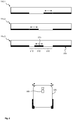
- Die Erfindung wird nun unter Bezug auf die beiliegenden Figuren genauer beschrieben, in denen:
- Fig. 1
- ein System mit einem Roboter in einer beispielhaften Ausführungsform;
- Fig. 2
- beispielhafte Ausführungsformen einer optischen Marke; und
- Fig. 3
- ein Ablaufdiagramm eines exemplarischen Verfahrens zum Steuern eines Roboters
-
Figur 1 zeigt ein System 100 mit einem beispielhafter Roboter 105, der dazu eingerichtet ist, eine Bodenfläche 110 zu bearbeiten. Das System 100 umfasst ferner eine oder mehrere Marken 115, wobei jede Marke 115 einer vorbestimmten Position 120 auf der Bodenfläche 110 zugeordnet ist. Rein beispielhaft ist eine erste Marke 115 (inFigur 1 links oben) im Bereich eines Mülleimers und eine zweite Marke 115 (inFigur 1 rechts oben) im Bereich einer Basisstation 125 dargestellt. Die Basisstation 125 kann insbesondere zur Energieversorgung bzw. zum Nachfüllen eines Energiespeichers des Roboters 105 eingerichtet sein. Ferner kann die Basisstation 125 eine Kommunikation des Roboters 105 mit einer externen Einrichtung unterstützen. Der Roboter 105 ist bevorzugt dazu eingerichtet, sich zur Basisstation 125 zu begeben, wenn er seiner vorbestimmten Tätigkeit, die Bodenfläche 110 zu bearbeiten, gerade nicht nachkommt. Die Basisstation 125 kann in einem unzugänglichen Bereich angeordnet sein, beispielsweise unterhalb eines Möbelstücks oder in einer engen Nische. - Der Roboter 105 ist bevorzugt dazu eingerichtet, die Bodenfläche 110 autonom abzufahren. Dafür erforderliche Umfeldsensoren und Kartenspeicher können im Wesentlichen dem Stand der Technik entsprechen und werden hier nicht gesondert betrachtet.
- Der Roboter 105 umfasst bevorzugt eine Bewegungseinheit 130 und eine Bearbeitungseinheit 135. Die Bewegungseinheit 130 ist dazu eingerichtet, den Roboter 105 steuerbar über die Bodenfläche 110 zu fahren und umfasst in der dargestellten Ausführungsform lediglich zwei Räder 140 mit zugeordneten Antriebsmotoren 145. Durch diese einfache Konstellation können bereits eine Längs- und Quersteuerung des Roboters 105 ermöglicht sein. Andere Aufbauten sind jedoch ebenfalls möglich. Die Bearbeitungseinheit 135 ist dazu eingerichtet, die Bodenfläche 110 zu bearbeiten. Insbesondere soll die Bearbeitung während des Abfahrens der Bodenfläche 110 erfolgen. Der Roboter 105 kann beispielsweise einen Reinigungsroboter umfassen, wobei die Bearbeitungseinheit 135 wie beispielhaft in
Figur 1 dargestellt ist, eine Saugvorrichtung 150 umfassen kann, die dazu eingerichtet ist, Schmutz 155 von der Bodenfläche 110 einzusammeln und in einem Behälter 160 zu sammeln. Zur Reinigung können auch eine oder mehrere bewegliche Bürsten 165 vorgesehen sein, die beispielsweise dazu eingerichtet sind, groben Schmutz 155 in Richtung der Saugvorrichtung 150 zu bewegen oder zu absorbieren. Andere Vorrichtungen sind ebenfalls möglich. - Der Roboter 105 ist bevorzugt mittels einer Steuervorrichtung 170 steuerbar. Es können auch mehrere Steuervorrichtungen 170 vorgesehen sein, die einzelnen Teilaufgaben der Steuerung des Roboters 105 zugeordnet sind. Die Elemente des Roboters 105 werden bevorzugt mittels Energie aus einem Energiespeicher 175 betrieben. Bevorzugt ist die Steuervorrichtung 170 noch mit wenigstens einer Abtasteinrichtung, insbesondere einem Umfeldsensor 180 zur Abtastung eines Umfelds des Roboters 105 und weiter bevorzugt einer Marke 115, sowie optional einer Speichervorrichtung 185 verbunden, in der Informationen insbesondere zur Navigation des Roboters 105 abgelegt werden können.
- Es wird vorgeschlagen, dass die Steuervorrichtung 170 dazu eingerichtet ist, einen Betriebszustand der Bearbeitungseinheit 135 zu bestimmen und, falls der Betriebszustand darauf hinweist, dass die Bearbeitung der Bodenfläche 110 mittels der Bearbeitungseinheit 135 in einer vorbestimmten Weise beeinträchtigt ist, die Bewegungseinheit 130 dazu anzusteuern, eine zugeordnete Position 120 anzufahren, die dem bestimmten Betriebszustand zugeordnet ist. An der Position 120 ist bevorzugt eine charakteristische Marke 115 angebracht, die mittels des Umfeldsensors 180 erfasst werden kann. Es ist besonders bevorzugt, dass unterschiedlichen Betriebszuständen unterschiedliche Positionen 120 zugeordnet sind. Insbesondere kann eine erste Position 120, die angesteuert wird, wenn ein erster Betriebszustand des Roboters 105 darauf hinweist, dass der Energiespeicher 175 aufgefüllt werden soll, verschieden sein von einer zweiten Position 120, die angesteuert wird, wenn der Betriebszustand darauf hinweist, dass der Behälter 160 voll oder eine der Bürsten 165 verklemmt ist.
-
Figur 2 zeigt beispielhafte Ausführungsformen einer Marke 115 zur Abtastung mittels des Umfeldsensors 180 des Roboters 105 vonFigur 1 . Die Marke 115 kann bevorzugt berührungslos abgetastet werden, beispielsweise optisch, mittels Radar, Lidar oder Ultraschall. Dabei kann die Marke 115 bevorzugt mechanisch konfiguriert werden, unterschiedliche Kennungen zu repräsentieren. Eine Kennung umfasst bevorzugt eine Sequenz (Datenwort) binärer Werte (Bits), wobei jedes Bit durch eine Reflexeigenschaft ausgedrückt werden kann. Jedes Bit ist einem geometrischen Abschnitt zugeordnet, wobei die Anordnung der Abschnitte die Lage der Bits im Datenwort bestimmt. Es ist bevorzugt, dass dieselbe Marke 115 dazu konfiguriert werden kann, unterschiedliche Kennungen zu realisieren bzw. repräsentieren. In der Darstellung vonFigur 1 ist die Marke 115 in drei unterschiedlichen Konfigurationen 115.1, 115.2 und 115.3 dargestellt. - In der dargestellten Ausführungsform umfasst die Marke 115 eine Oberfläche 205, die bevorzugt gerade bzw. eben verläuft. Die Oberfläche 205 ist in mehrere Abschnitte 210 unterteilt, wobei jedem Abschnitt 210 eine Reflexeigenschaft für ein Signal zugeordnet ist, welches mittels des Umfeldsensors 180 abgetastet werden kann. Dieses Signal kann beispielsweise Licht, eine Radarsignal oder ein Ultraschallsignal umfassen. Bevorzugt ist wenigstens ein bewegliches Element 215 vorgesehen, welches in mindestens eine erste Stellung bewegt werden kann, in welcher es in einem Abschnitt 210 liegt, und eine zweite Stellung, in welcher es sich außerhalb dieses Abschnitts 210 befindet. Das Element 215 kann beispielsweise einen Schieber, eine Klappe oder eine drehbare Blende umfassen. Befindet sich das Element 215 im Abschnitt 210, so kann das beschriebene Signal in den Bereich des Umfeldsensors 180 reflektiert werden. Befindet sich das Element 215 in der zweiten Position, ist aus dem Bereich des zugeordneten Abschnitts 210 keine oder nur eine geringe Signalreflexion zu erwarten. In der dargestellten Ausführungsform umfasst die Marke 115 einen Hohlkörper 220, der sich an die Oberfläche 205 anschließt. Der Hohlkörper 220 kann verhindern, dass das Signal beispielsweise von hinten durch einen Abschnitt 210 zum Umfeldsensor 180 gelangt.
- Mehrere Abschnitte 210 können ein zwei- oder dreidimensionales binäres Muster bilden, welches nach Art eines 2D- oder 3D-Strichcodes (QR-Code) mittels des Umfeldsensors 180 erfasst werden kann. Dadurch kann das Datenwort abgetastet werden, das durch die Stellungen der Elemente an den Abschnitten 210 konfiguriert ist. Dieses Datenwort kann einem vorbestimmten Betriebszustand des Roboters 105 zugeordnet sein. Der Ort, an dem die Marke 115 aufgestellt ist, ist die Position der Marke 115 und die Position 120, zu der sich der Roboter 105 im vorbestimmten Betriebszustand begibt.
- In einer Ausführungsform ist die Marke 115 so konfiguriert, dass mehrere Elemente 215 gleichzeitig in benachbarten Abschnitten 210 bewegt werden können, sodass mehrere vorbestimmte Kennungen auf einfache Weise repräsentiert werden können. Jeder Kennung kann beispielsweise ein vorbestimmter Betriebszustand zugeordnet sein, den der Roboter 105 einnimmt, wenn er eine Position 120 aufsucht, an der die entsprechende Kennung angebracht ist. Die Elemente 215 können so markiert sein, dass der Betriebszustand, auf den die Stellung der Elemente 215 hinweist, beispielsweise als Aufdruck von einem Benutzer gelesen bzw. erkannt werden können.
-
Figur 3 zeigt ein Ablaufdiagramm eines exemplarischen Verfahrens 300 zum Steuern eines Roboters 105, insbesondere nach Art vonFigur 1 . Das Verfahren 300 ist insbesondere zum Ablaufen auf der Steuervorrichtung 170 eingerichtet. In einer Ausführungsform ist das dargestellte Verfahren 300 Teil eines übergeordneten Navigations- bzw. Arbeitsverfahrens. Das dargestellte Verfahren 300 kann beispielsweise periodisch durchlaufen werden, etwa minütlich oder beispielsweise alle ca. 10 bis 20 Sekunden. Das Verfahren 300 kann das übergeordnete Verfahren auch unterbrechen oder abändern. - Das Verfahren 300 beginnt in einem Schritt 305. In einem Schritt 310 kann ein Betriebszustand der Bearbeitungseinheit 135 bestimmt werden. Der Betriebszustand kann in einem Schritt 315 untersucht werden, insbesondere dahingehend, ob der bestimmte Betriebszustand darauf hinweist, dass die Bearbeitung der Bodenfläche 110 mittels der Bearbeitungseinheit 135 beeinträchtigt ist. Ist dies nicht der Fall, so kann das Verfahren 300 in einem Schritt 320 enden bzw. die Kontrolle an das übergeordnete Verfahren zurückgeben.
- Andernfalls, wenn eine Beeinträchtigung zu erwarten ist, kann eine Maßnahme ergriffen werden, um die Bearbeitungseinheit 135 in die Lage zu versetzen, die Bearbeitung der Bodenfläche 110 fortzuführen. Dies ist mit einer Fahrt des Roboters 105 zu einer vorbestimmten Position 120 verbunden. Optional kann an dieser Stelle in einem Schritt 325 überprüft werden, ob zudem der Energiespeicher 175 aufgeladen werden soll. In diesem Fall kann in einem Schritt 330 der Roboter 105 zur vorbestimmten Position 120 einer Basisstation 125 gefahren werden und in einem Schritt 335 kann der Energiespeicher 175 aufgeladen werden. Die Schritte 325 bis 335 können jedoch auch an anderen Stellen des Verfahrens 300 durchgeführt werden, insbesondere immer unmittelbar vor dem Schritt 320.
- In einem Schritt 340 wird eine Position 120 bestimmt, die dem bestimmten Betriebszustand der Bearbeitungseinheit 135 zugeordnet ist. Die Position 120 kann durch eine Marke 115 gekennzeichnet sein, die eine vorbestimmte Kennung repräsentiert. Es wird davon ausgegangen, dass der Roboter 105 die Position 120 bezüglich seiner eigenen Position kennt, beispielsweise weil der die korrespondierende Marke 115 bereits zuvor beim Abfahren der Bodenfläche 110 passiert und mittels des Umfeldsensors 180 abgetastet hat. Andernfalls kann der Roboter 105 an dieser Stelle ein Suchverfahren beginnen, um die Position 120 zu lokalisieren.
- In einem Schritt 345 kann der Roboter 105 dazu angesteuert werden, zur vorbestimmten Position 120 zu fahren. Dort kann der Roboter 105 darauf warten, dass ein erforderlicher Serviceeingriff erfolgt ist. In einer Ausführungsform wird in einem Schritt 350 lediglich das Stattfinden eines solchen Eingriffs geprüft, in einer bevorzugten Ausführungsform wird zusätzlich geprüft, ob sich - infolge des Eingriffs - der Betriebszustand der Bearbeitungseinheit 135 geändert hat, und zwar so, dass er nicht mehr auf eine Beeinträchtigung der Funktionsweise bzw. Leistungsfähigkeit der Bearbeitungseinheit 135 hinweist. Ist dies der Fall, so kann das Verfahren 300 im Schritt 320 enden.
- Optional kann zuvor jedoch in einem Schritt 355 die Bodenfläche 110 im Bereich der vorbestimmten Position 120, an der sich der Roboter 105 befindet, bearbeitet werden. Dazu kann beispielsweise ein vorbestimmter Bereich um die vorbestimmte Position 120 durch den Roboter 105 abgefahren werden, wobei die Bodenfläche 110 mittels der Bearbeitungseinheit 135 bearbeitet wird. Befindet sich der Roboter 105 beispielsweise an der in
Figur 1 oben links dargestellten vorbestimmten Position 120, um den Behälter 160 durch einen Benutzer ausleeren zu lassen, so kann bei diesem Entleeren ein Teils des zuvor aufgesammelten Schmutzes 155 unkontrolliert auf die Bodenfläche 110 fallen. Durch das vorsorgliche Abfahren und - in diesem Fall - Reinigen der Bodenfläche 110 in diesem Bereich kann verhindert werden, dass der Schmutz 155 weiter ausgebreitet wird. -
- 100
- System
- 105
- Roboter
- 110
- Bodenfläche
- 115
- Marke
- 120
- vorbestimmte Position
- 125
- Basisstation
- 130
- Bewegungseinheit
- 135
- Bearbeitungseinheit
- 140
- Rad
- 145
- Motor
- 150
- Saugvorrichtung
- 155
- Schmutz
- 160
- Behälter
- 165
- bewegliche Bürste
- 170
- Steuervorrichtung
- 175
- Energiespeicher
- 180
- Umfeldsensor / Abtasteinrichtung
- 185
- Speichervorrichtung
- 205
- Oberfläche
- 210
- Abschnitt
- 215
- Element
- 220
- Hohlkörper
- 300
- Verfahren
- 305
- Start
- 310
- Bestimmen Betriebszustand Bearbeitungseinheit
- 315
- Bearbeitung beeinträchtigt?
- 320
- Ende
- 325
- Energiespeicher aufladen?
- 330
- Fahren zur Basisstation
- 335
- Aufladen
- 340
- Bestimmen zugeordnete Position
- 345
- Fahren zur Position
- 350
- Betriebszustand geändert?
- 355
- Boden im Bereich der Position bearbeiten
Claims (12)
- Verfahren (300) zum Steuern eines Roboters (105), insbesondere eines Reinigungsroboters, der eine Bewegungseinheit (130) zum Fahren des Roboters (105) über eine Bodenfläche (110), und eine Bearbeitungseinheit (135) zur Bearbeitung der abgefahrenen Bodenfläche (110) umfasst, wobei das Verfahren (300) folgende Schritte umfasst:- Erfassen (310) eines Betriebszustands der Bearbeitungseinheit (135);- Bestimmen (315), dass der erfasste Betriebszustand die Bearbeitung beeinträchtigt; und- Ansteuern (345) der Bewegungseinheit (130), um den Roboter (105) zu einer vorbestimmten Position (120) zu fahren, die dem erfassten Betriebszustand zugewiesen ist, wobei sich die Position insbesondere in einem Bereich eines Abfalleimers befindet.
- Verfahren (300) nach Anspruch 1, wobei die Position (120) von einer weiteren Position (120) verschieden ist, die einem Betriebszustand zugeordnet ist, in dem ein Energiespeicher (175) des Roboters (105) nachgefüllt werden soll.
- Verfahren (300) nach einem der vorangehenden Ansprüche, wobei die Bearbeitungseinheit (135) dazu eingerichtet ist, Schmutz (155) von der Bodenfläche (110) in einen Behälter (160) zu sammeln und der Betriebszustand einen vorbestimmten Füllstand des Behälters (160) umfasst.
- Verfahren (300) nach einem der vorangehenden Ansprüche, wobei die Bearbeitungseinheit (135) eine bewegliche Bürste (165) umfasst und der Betriebszustand eine mangelnde Beweglichkeit der Bürste (165) umfasst.
- Verfahren (300) nach einem der vorangehenden Ansprüche, ferner umfassend ein Erfassen (350), dass der Betriebszustand die Bodenreinigung nicht mehr beeinträchtigt, während sich der Roboter (105) an der vorbestimmten Position (120) befindet, und ein anschließendes Bearbeiten (355) der Bodenfläche (110) in einem Bereich um die vorbestimmte Position (120).
- Verfahren (300) nach einem der vorangehenden Ansprüche, ferner umfassend ein Deaktivieren der Bearbeitungseinheit (135) während der Fahrt zur vorbestimmten Position (120).
- Verfahren (300) nach einem der vorangehenden Ansprüche, wobei die Position (120) mittels optischer Erfassung einer an der Position (120) angebrachten vorbestimmten Marke (115) erfolgt, wobei die Marke insbesondere an einem Abfalleimer angeordnet ist.
- Steuervorrichtung (170) für einen Roboter (105), der eine Bewegungseinheit (130) zum Fahren des Roboters (105) über eine Bodenfläche (110), und eine Bearbeitungseinheit (135) zur Bearbeitung der abgefahrenen Bodenfläche (110) umfasst, wobei die Steuervorrichtung (170) dazu eingerichtet ist:- einen Betriebszustand der Bearbeitungseinheit (135) zu erfassen;- zu bestimmen, dass der erfasste Betriebszustand die Bearbeitung beeinträchtigt; und- die Bewegungseinheit (130) anzusteuern, um den Roboter (105) zu einer vorbestimmten Position (120) zu fahren, die dem erfassten Betriebszustand zugewiesen ist.
- Roboter (105), insbesondere Reinigungsroboter, mit einer Steuervorrichtung (170) nach Anspruch 8.
- Roboter (105) nach Anspruch 9, ferner umfassend eine Abtasteinrichtung (180) zur optischen Erfassung einer vorbestimmten Marke (115), wobei die Marke (115) der Position (120) zugeordnet ist.
- System (100), umfassend einen Roboter (105) nach Anspruch 10 und die Marke (115), wobei die Marke (115) mehrere Abschnitte (210) umfasst, von denen wenigstens einer in seinen Reflexeigenschaften binär verändert werden kann.
- System (100) nach Anspruch 11, wobei ein bewegliches Element (215) mit zwei Stellungen vorgesehen ist, sodass sich das Element (215) in einer ersten Stellung im Bereich des Abschnitts (210) und in einer zweiten Stellung außerhalb des Abschnitts (210) befindet.
Applications Claiming Priority (1)
| Application Number | Priority Date | Filing Date | Title |
|---|---|---|---|
| DE102017213426.7A DE102017213426A1 (de) | 2017-08-02 | 2017-08-02 | Roboter zur Bodenbearbeitung |
Publications (2)
| Publication Number | Publication Date |
|---|---|
| EP3437538A1 true EP3437538A1 (de) | 2019-02-06 |
| EP3437538B1 EP3437538B1 (de) | 2021-11-17 |
Family
ID=62948010
Family Applications (1)
| Application Number | Title | Priority Date | Filing Date |
|---|---|---|---|
| EP18183148.8A Active EP3437538B1 (de) | 2017-08-02 | 2018-07-12 | Roboter zur bodenbearbeitung |
Country Status (2)
| Country | Link |
|---|---|
| EP (1) | EP3437538B1 (de) |
| DE (1) | DE102017213426A1 (de) |
Citations (6)
| Publication number | Priority date | Publication date | Assignee | Title |
|---|---|---|---|---|
| DE102009003748A1 (de) | 2009-04-06 | 2010-10-07 | Vorwerk & Co. Interholding Gmbh | Bodenstaub-Aufsammelgerät sowie Verfahren eines solchen Geräts, weiter Positionsmarke für ein Arbeitsgerät |
| DE102010016263A1 (de) | 2010-03-31 | 2011-10-06 | Vorwerk & Co. Interholding Gmbh | Basisstation für einen Saug- und/oder Kehrroboter |
| JP2013192678A (ja) * | 2012-03-19 | 2013-09-30 | Sharp Corp | ロボット装置、情報提供装置、情報提供システム及びプログラム |
| US20150148951A1 (en) * | 2013-11-27 | 2015-05-28 | Electronics And Telecommunications Research Institute | Method and control apparatus for cooperative cleaning using multiple robots |
| DE102015113035A1 (de) * | 2015-08-07 | 2017-02-09 | Vorwerk & Co. Interholding Gmbh | Flächenbearbeitungsgerät und Basisstation |
| US20170156560A1 (en) * | 2014-07-01 | 2017-06-08 | Samsung Electronics Co., Ltd. | Cleaning robot and controlling method thereof |
Family Cites Families (3)
| Publication number | Priority date | Publication date | Assignee | Title |
|---|---|---|---|---|
| JP2005224263A (ja) * | 2004-02-10 | 2005-08-25 | Funai Electric Co Ltd | 自走式掃除機 |
| KR100762095B1 (ko) * | 2006-06-29 | 2007-10-05 | 주식회사 로보스템 | 유 무선 자주식 청소기의 전원 공급을 위한 피동이동충전스테이션 |
| DE102012221572A1 (de) * | 2012-11-26 | 2014-05-28 | Robert Bosch Gmbh | Autonomes Fortbewegungsgerät |
-
2017
- 2017-08-02 DE DE102017213426.7A patent/DE102017213426A1/de not_active Withdrawn
-
2018
- 2018-07-12 EP EP18183148.8A patent/EP3437538B1/de active Active
Patent Citations (6)
| Publication number | Priority date | Publication date | Assignee | Title |
|---|---|---|---|---|
| DE102009003748A1 (de) | 2009-04-06 | 2010-10-07 | Vorwerk & Co. Interholding Gmbh | Bodenstaub-Aufsammelgerät sowie Verfahren eines solchen Geräts, weiter Positionsmarke für ein Arbeitsgerät |
| DE102010016263A1 (de) | 2010-03-31 | 2011-10-06 | Vorwerk & Co. Interholding Gmbh | Basisstation für einen Saug- und/oder Kehrroboter |
| JP2013192678A (ja) * | 2012-03-19 | 2013-09-30 | Sharp Corp | ロボット装置、情報提供装置、情報提供システム及びプログラム |
| US20150148951A1 (en) * | 2013-11-27 | 2015-05-28 | Electronics And Telecommunications Research Institute | Method and control apparatus for cooperative cleaning using multiple robots |
| US20170156560A1 (en) * | 2014-07-01 | 2017-06-08 | Samsung Electronics Co., Ltd. | Cleaning robot and controlling method thereof |
| DE102015113035A1 (de) * | 2015-08-07 | 2017-02-09 | Vorwerk & Co. Interholding Gmbh | Flächenbearbeitungsgerät und Basisstation |
Also Published As
| Publication number | Publication date |
|---|---|
| DE102017213426A1 (de) | 2019-02-07 |
| EP3437538B1 (de) | 2021-11-17 |
Similar Documents
| Publication | Publication Date | Title |
|---|---|---|
| DE102004004505B9 (de) | Bodenbearbeitungsgerät sowie Verfahren zu dessen Steuerung | |
| DE10261787B3 (de) | Mobiles Bodenbearbeitungsgerät | |
| EP1967116B2 (de) | Verfahren zur Reinigung einer Bodenfläche mittels eines selbstfahrenden Reinigungsgerätes, insbesondere eines Robotsaugers | |
| EP3234715B1 (de) | Verfahren zur kartierung einer bearbeitungsfläche für autonome roboterfahrzeuge | |
| DE102015016527A1 (de) | Interne Reinigungsvorrichtung einer Werkzeugmaschine | |
| EP2768297B1 (de) | Autonomes arbeitsgerät | |
| DE102016119973A1 (de) | Werkzeugreinigungsvorrichtung für Werkzeugmaschine | |
| EP3618677B1 (de) | Reinigungsvorrichtung und verfahren zum betreiben einer reinigungsvorrichtung | |
| WO2013041278A1 (de) | Autonomes arbeitsgerät | |
| DE102009041362A1 (de) | Verfahren zum Betreiben eines Reinigungsroboters | |
| DE102016205336A1 (de) | Autonome Vorrichtung zur Behandlung von Unkraut | |
| DE102017100299A1 (de) | Sich selbsttätig fortbewegendes Reinigungsgerät | |
| EP3441842A1 (de) | Verfahren zum betrieb eines sich selbsttätig fortbewegenden bodenbearbeitungsgerätes | |
| DE102017113288A1 (de) | System mit mindestens zwei Bodenbearbeitungseinrichtungen | |
| EP3584559B1 (de) | Verschleissprognoseverfahren für eine bodenbearbeitungsmaschine | |
| EP3416018A1 (de) | System mit mindestens zwei bodenbearbeitungsgeräten | |
| EP3569129A1 (de) | Verfahren zur bestimmung einer route für eine bodenreinigungsmaschine | |
| DE102019101337A1 (de) | System mit einem ersten Bodenbearbeitungsgerät und einem zweiten Bodenbearbeitungsgerät sowie Verfahren zum Betrieb eines solchen Systems | |
| DE102017113286A1 (de) | System mit mindestens zwei sich selbsttätig fortbewegenden Bodenbearbeitungsgeräten | |
| DE102015122149A1 (de) | Verfahren zum autonomen Betrieb einer Verdichtungsvorrichtung | |
| DE102019131583A1 (de) | System mit mindestens zwei sich selbsttätig fortbewegenden Bodenbearbeitungsgeräten sowie Verfahren zum Betrieb eines Systems | |
| WO2020144011A1 (de) | Verfahren zum betreiben eines reinigungsfahrzeugs | |
| DE10346216B3 (de) | Verfahren zur Reinigung einer Bodenfläche mittels eines Bodenreinigungssystems und Bodenreinigungssystem zur Durchführung des Verfahrens | |
| DE102021200401B3 (de) | Verfahren zur autonomen Bearbeitung von Bodenflächen | |
| DE102011055764A1 (de) | Verfahren zur Bearbeitung einer textilen Bodenfläche mittels eines Bodenreinigungsgerätes sowie Bodenreinigungsgerät |
Legal Events
| Date | Code | Title | Description |
|---|---|---|---|
| PUAI | Public reference made under article 153(3) epc to a published international application that has entered the european phase |
Free format text: ORIGINAL CODE: 0009012 |
|
| STAA | Information on the status of an ep patent application or granted ep patent |
Free format text: STATUS: THE APPLICATION HAS BEEN PUBLISHED |
|
| AK | Designated contracting states |
Kind code of ref document: A1 Designated state(s): AL AT BE BG CH CY CZ DE DK EE ES FI FR GB GR HR HU IE IS IT LI LT LU LV MC MK MT NL NO PL PT RO RS SE SI SK SM TR |
|
| AX | Request for extension of the european patent |
Extension state: BA ME |
|
| STAA | Information on the status of an ep patent application or granted ep patent |
Free format text: STATUS: REQUEST FOR EXAMINATION WAS MADE |
|
| 17P | Request for examination filed |
Effective date: 20190806 |
|
| RBV | Designated contracting states (corrected) |
Designated state(s): AL AT BE BG CH CY CZ DE DK EE ES FI FR GB GR HR HU IE IS IT LI LT LU LV MC MK MT NL NO PL PT RO RS SE SI SK SM TR |
|
| RIC1 | Information provided on ipc code assigned before grant |
Ipc: A47L 9/28 20060101AFI20210527BHEP |
|
| GRAP | Despatch of communication of intention to grant a patent |
Free format text: ORIGINAL CODE: EPIDOSNIGR1 |
|
| STAA | Information on the status of an ep patent application or granted ep patent |
Free format text: STATUS: GRANT OF PATENT IS INTENDED |
|
| INTG | Intention to grant announced |
Effective date: 20210705 |
|
| GRAS | Grant fee paid |
Free format text: ORIGINAL CODE: EPIDOSNIGR3 |
|
| GRAA | (expected) grant |
Free format text: ORIGINAL CODE: 0009210 |
|
| STAA | Information on the status of an ep patent application or granted ep patent |
Free format text: STATUS: THE PATENT HAS BEEN GRANTED |
|
| AK | Designated contracting states |
Kind code of ref document: B1 Designated state(s): AL AT BE BG CH CY CZ DE DK EE ES FI FR GB GR HR HU IE IS IT LI LT LU LV MC MK MT NL NO PL PT RO RS SE SI SK SM TR |
|
| REG | Reference to a national code |
Ref country code: GB Ref legal event code: FG4D Free format text: NOT ENGLISH |
|
| REG | Reference to a national code |
Ref country code: DE Ref legal event code: R096 Ref document number: 502018007864 Country of ref document: DE |
|
| REG | Reference to a national code |
Ref country code: IE Ref legal event code: FG4D Free format text: LANGUAGE OF EP DOCUMENT: GERMAN |
|
| REG | Reference to a national code |
Ref country code: AT Ref legal event code: REF Ref document number: 1447375 Country of ref document: AT Kind code of ref document: T Effective date: 20211215 |
|
| REG | Reference to a national code |
Ref country code: LT Ref legal event code: MG9D |
|
| REG | Reference to a national code |
Ref country code: NL Ref legal event code: MP Effective date: 20211117 |
|
| PG25 | Lapsed in a contracting state [announced via postgrant information from national office to epo] |
Ref country code: RS Free format text: LAPSE BECAUSE OF FAILURE TO SUBMIT A TRANSLATION OF THE DESCRIPTION OR TO PAY THE FEE WITHIN THE PRESCRIBED TIME-LIMIT Effective date: 20211117 Ref country code: LT Free format text: LAPSE BECAUSE OF FAILURE TO SUBMIT A TRANSLATION OF THE DESCRIPTION OR TO PAY THE FEE WITHIN THE PRESCRIBED TIME-LIMIT Effective date: 20211117 Ref country code: FI Free format text: LAPSE BECAUSE OF FAILURE TO SUBMIT A TRANSLATION OF THE DESCRIPTION OR TO PAY THE FEE WITHIN THE PRESCRIBED TIME-LIMIT Effective date: 20211117 Ref country code: BG Free format text: LAPSE BECAUSE OF FAILURE TO SUBMIT A TRANSLATION OF THE DESCRIPTION OR TO PAY THE FEE WITHIN THE PRESCRIBED TIME-LIMIT Effective date: 20220217 |
|
| PG25 | Lapsed in a contracting state [announced via postgrant information from national office to epo] |
Ref country code: IS Free format text: LAPSE BECAUSE OF FAILURE TO SUBMIT A TRANSLATION OF THE DESCRIPTION OR TO PAY THE FEE WITHIN THE PRESCRIBED TIME-LIMIT Effective date: 20220317 Ref country code: SE Free format text: LAPSE BECAUSE OF FAILURE TO SUBMIT A TRANSLATION OF THE DESCRIPTION OR TO PAY THE FEE WITHIN THE PRESCRIBED TIME-LIMIT Effective date: 20211117 Ref country code: PT Free format text: LAPSE BECAUSE OF FAILURE TO SUBMIT A TRANSLATION OF THE DESCRIPTION OR TO PAY THE FEE WITHIN THE PRESCRIBED TIME-LIMIT Effective date: 20220317 Ref country code: PL Free format text: LAPSE BECAUSE OF FAILURE TO SUBMIT A TRANSLATION OF THE DESCRIPTION OR TO PAY THE FEE WITHIN THE PRESCRIBED TIME-LIMIT Effective date: 20211117 Ref country code: NO Free format text: LAPSE BECAUSE OF FAILURE TO SUBMIT A TRANSLATION OF THE DESCRIPTION OR TO PAY THE FEE WITHIN THE PRESCRIBED TIME-LIMIT Effective date: 20220217 Ref country code: NL Free format text: LAPSE BECAUSE OF FAILURE TO SUBMIT A TRANSLATION OF THE DESCRIPTION OR TO PAY THE FEE WITHIN THE PRESCRIBED TIME-LIMIT Effective date: 20211117 Ref country code: LV Free format text: LAPSE BECAUSE OF FAILURE TO SUBMIT A TRANSLATION OF THE DESCRIPTION OR TO PAY THE FEE WITHIN THE PRESCRIBED TIME-LIMIT Effective date: 20211117 Ref country code: HR Free format text: LAPSE BECAUSE OF FAILURE TO SUBMIT A TRANSLATION OF THE DESCRIPTION OR TO PAY THE FEE WITHIN THE PRESCRIBED TIME-LIMIT Effective date: 20211117 Ref country code: GR Free format text: LAPSE BECAUSE OF FAILURE TO SUBMIT A TRANSLATION OF THE DESCRIPTION OR TO PAY THE FEE WITHIN THE PRESCRIBED TIME-LIMIT Effective date: 20220218 Ref country code: ES Free format text: LAPSE BECAUSE OF FAILURE TO SUBMIT A TRANSLATION OF THE DESCRIPTION OR TO PAY THE FEE WITHIN THE PRESCRIBED TIME-LIMIT Effective date: 20211117 |
|
| PG25 | Lapsed in a contracting state [announced via postgrant information from national office to epo] |
Ref country code: SM Free format text: LAPSE BECAUSE OF FAILURE TO SUBMIT A TRANSLATION OF THE DESCRIPTION OR TO PAY THE FEE WITHIN THE PRESCRIBED TIME-LIMIT Effective date: 20211117 Ref country code: SK Free format text: LAPSE BECAUSE OF FAILURE TO SUBMIT A TRANSLATION OF THE DESCRIPTION OR TO PAY THE FEE WITHIN THE PRESCRIBED TIME-LIMIT Effective date: 20211117 Ref country code: RO Free format text: LAPSE BECAUSE OF FAILURE TO SUBMIT A TRANSLATION OF THE DESCRIPTION OR TO PAY THE FEE WITHIN THE PRESCRIBED TIME-LIMIT Effective date: 20211117 Ref country code: EE Free format text: LAPSE BECAUSE OF FAILURE TO SUBMIT A TRANSLATION OF THE DESCRIPTION OR TO PAY THE FEE WITHIN THE PRESCRIBED TIME-LIMIT Effective date: 20211117 Ref country code: DK Free format text: LAPSE BECAUSE OF FAILURE TO SUBMIT A TRANSLATION OF THE DESCRIPTION OR TO PAY THE FEE WITHIN THE PRESCRIBED TIME-LIMIT Effective date: 20211117 Ref country code: CZ Free format text: LAPSE BECAUSE OF FAILURE TO SUBMIT A TRANSLATION OF THE DESCRIPTION OR TO PAY THE FEE WITHIN THE PRESCRIBED TIME-LIMIT Effective date: 20211117 |
|
| REG | Reference to a national code |
Ref country code: DE Ref legal event code: R097 Ref document number: 502018007864 Country of ref document: DE |
|
| PLBE | No opposition filed within time limit |
Free format text: ORIGINAL CODE: 0009261 |
|
| STAA | Information on the status of an ep patent application or granted ep patent |
Free format text: STATUS: NO OPPOSITION FILED WITHIN TIME LIMIT |
|
| 26N | No opposition filed |
Effective date: 20220818 |
|
| PG25 | Lapsed in a contracting state [announced via postgrant information from national office to epo] |
Ref country code: AL Free format text: LAPSE BECAUSE OF FAILURE TO SUBMIT A TRANSLATION OF THE DESCRIPTION OR TO PAY THE FEE WITHIN THE PRESCRIBED TIME-LIMIT Effective date: 20211117 |
|
| PG25 | Lapsed in a contracting state [announced via postgrant information from national office to epo] |
Ref country code: SI Free format text: LAPSE BECAUSE OF FAILURE TO SUBMIT A TRANSLATION OF THE DESCRIPTION OR TO PAY THE FEE WITHIN THE PRESCRIBED TIME-LIMIT Effective date: 20211117 |
|
| PG25 | Lapsed in a contracting state [announced via postgrant information from national office to epo] |
Ref country code: MC Free format text: LAPSE BECAUSE OF FAILURE TO SUBMIT A TRANSLATION OF THE DESCRIPTION OR TO PAY THE FEE WITHIN THE PRESCRIBED TIME-LIMIT Effective date: 20211117 |
|
| REG | Reference to a national code |
Ref country code: CH Ref legal event code: PL |
|
| REG | Reference to a national code |
Ref country code: BE Ref legal event code: MM Effective date: 20220731 |
|
| PG25 | Lapsed in a contracting state [announced via postgrant information from national office to epo] |
Ref country code: LU Free format text: LAPSE BECAUSE OF NON-PAYMENT OF DUE FEES Effective date: 20220712 Ref country code: LI Free format text: LAPSE BECAUSE OF NON-PAYMENT OF DUE FEES Effective date: 20220731 Ref country code: CH Free format text: LAPSE BECAUSE OF NON-PAYMENT OF DUE FEES Effective date: 20220731 |
|
| PG25 | Lapsed in a contracting state [announced via postgrant information from national office to epo] |
Ref country code: IT Free format text: LAPSE BECAUSE OF FAILURE TO SUBMIT A TRANSLATION OF THE DESCRIPTION OR TO PAY THE FEE WITHIN THE PRESCRIBED TIME-LIMIT Effective date: 20211117 Ref country code: BE Free format text: LAPSE BECAUSE OF NON-PAYMENT OF DUE FEES Effective date: 20220731 |
|
| PG25 | Lapsed in a contracting state [announced via postgrant information from national office to epo] |
Ref country code: IE Free format text: LAPSE BECAUSE OF NON-PAYMENT OF DUE FEES Effective date: 20220712 |
|
| PG25 | Lapsed in a contracting state [announced via postgrant information from national office to epo] |
Ref country code: HU Free format text: LAPSE BECAUSE OF FAILURE TO SUBMIT A TRANSLATION OF THE DESCRIPTION OR TO PAY THE FEE WITHIN THE PRESCRIBED TIME-LIMIT; INVALID AB INITIO Effective date: 20180712 |
|
| PG25 | Lapsed in a contracting state [announced via postgrant information from national office to epo] |
Ref country code: MK Free format text: LAPSE BECAUSE OF FAILURE TO SUBMIT A TRANSLATION OF THE DESCRIPTION OR TO PAY THE FEE WITHIN THE PRESCRIBED TIME-LIMIT Effective date: 20211117 Ref country code: CY Free format text: LAPSE BECAUSE OF FAILURE TO SUBMIT A TRANSLATION OF THE DESCRIPTION OR TO PAY THE FEE WITHIN THE PRESCRIBED TIME-LIMIT Effective date: 20211117 |
|
| PG25 | Lapsed in a contracting state [announced via postgrant information from national office to epo] |
Ref country code: TR Free format text: LAPSE BECAUSE OF FAILURE TO SUBMIT A TRANSLATION OF THE DESCRIPTION OR TO PAY THE FEE WITHIN THE PRESCRIBED TIME-LIMIT Effective date: 20211117 |
|
| REG | Reference to a national code |
Ref country code: AT Ref legal event code: MM01 Ref document number: 1447375 Country of ref document: AT Kind code of ref document: T Effective date: 20230712 |
|
| PG25 | Lapsed in a contracting state [announced via postgrant information from national office to epo] |
Ref country code: MT Free format text: LAPSE BECAUSE OF FAILURE TO SUBMIT A TRANSLATION OF THE DESCRIPTION OR TO PAY THE FEE WITHIN THE PRESCRIBED TIME-LIMIT Effective date: 20211117 |
|
| PG25 | Lapsed in a contracting state [announced via postgrant information from national office to epo] |
Ref country code: AT Free format text: LAPSE BECAUSE OF NON-PAYMENT OF DUE FEES Effective date: 20230712 |
|
| PG25 | Lapsed in a contracting state [announced via postgrant information from national office to epo] |
Ref country code: AT Free format text: LAPSE BECAUSE OF NON-PAYMENT OF DUE FEES Effective date: 20230712 |
|
| PGFP | Annual fee paid to national office [announced via postgrant information from national office to epo] |
Ref country code: DE Payment date: 20250731 Year of fee payment: 8 |
|
| PGFP | Annual fee paid to national office [announced via postgrant information from national office to epo] |
Ref country code: GB Payment date: 20250724 Year of fee payment: 8 |
|
| PGFP | Annual fee paid to national office [announced via postgrant information from national office to epo] |
Ref country code: FR Payment date: 20250723 Year of fee payment: 8 |
|
| PGFP | Annual fee paid to national office [announced via postgrant information from national office to epo] |
Ref country code: AT Payment date: 20260410 Year of fee payment: 5 |