EP3437502A1 - Device and method for water-sealing the connection of a glove with a cuff - Google Patents

Device and method for water-sealing the connection of a glove with a cuff Download PDF

Info

Publication number
EP3437502A1
EP3437502A1 EP17184959.9A EP17184959A EP3437502A1 EP 3437502 A1 EP3437502 A1 EP 3437502A1 EP 17184959 A EP17184959 A EP 17184959A EP 3437502 A1 EP3437502 A1 EP 3437502A1
Authority
EP
European Patent Office
Prior art keywords
ring
groove
longitudinal direction
decoupling device
sealing
Prior art date
Legal status (The legal status is an assumption and is not a legal conclusion. Google has not performed a legal analysis and makes no representation as to the accuracy of the status listed.)
Withdrawn
Application number
EP17184959.9A
Other languages
German (de)
French (fr)
Inventor
Wendelin Egli
Current Assignee (The listed assignees may be inaccurate. Google has not performed a legal analysis and makes no representation or warranty as to the accuracy of the list.)
Splashlight GmbH
Original Assignee
Splashlight GmbH
Priority date (The priority date is an assumption and is not a legal conclusion. Google has not performed a legal analysis and makes no representation as to the accuracy of the date listed.)
Filing date
Publication date
Application filed by Splashlight GmbH filed Critical Splashlight GmbH
Priority to EP17184959.9A priority Critical patent/EP3437502A1/en
Priority to DE202018101809.4U priority patent/DE202018101809U1/en
Publication of EP3437502A1 publication Critical patent/EP3437502A1/en
Withdrawn legal-status Critical Current

Links

Images

Classifications

    • AHUMAN NECESSITIES
    • A41WEARING APPAREL
    • A41DOUTERWEAR; PROTECTIVE GARMENTS; ACCESSORIES
    • A41D19/00Gloves
    • A41D19/0055Plastic or rubber gloves
    • A41D19/0082Details
    • A41D19/0089Joints between glove and cuff or garment
    • AHUMAN NECESSITIES
    • A41WEARING APPAREL
    • A41DOUTERWEAR; PROTECTIVE GARMENTS; ACCESSORIES
    • A41D13/00Professional, industrial or sporting protective garments, e.g. surgeons' gowns or garments protecting against blows or punches
    • A41D13/0002Details of protective garments not provided for in groups A41D13/0007 - A41D13/1281
    • A41D13/0005Joints
    • BPERFORMING OPERATIONS; TRANSPORTING
    • B63SHIPS OR OTHER WATERBORNE VESSELS; RELATED EQUIPMENT
    • B63CLAUNCHING, HAULING-OUT, OR DRY-DOCKING OF VESSELS; LIFE-SAVING IN WATER; EQUIPMENT FOR DWELLING OR WORKING UNDER WATER; MEANS FOR SALVAGING OR SEARCHING FOR UNDERWATER OBJECTS
    • B63C11/00Equipment for dwelling or working underwater; Means for searching for underwater objects
    • B63C11/02Divers' equipment
    • B63C11/04Resilient suits
    • B63C2011/043Dry suits; Equipment therefor

Abstract

Vorrichtung (1) zum wasserdichten Verbinden eines Handschuhs mit einer Manschette eines Trockentauchanzugs, umfassend: einen ersten Ring (2), der abdichtend an der Manschette oder dem Handschuh befestigbar ist, einen zweiten Ring (3), der abdichtend am Handschuh oder an der Manschette befestigbar ist, sowie einen Dichtring (4), wobei der erste Ring (2) eine aussen umfänglich verlaufende erste Nut (2b) sowie eine senkrecht zur ersten Nut (2b) verlaufende Längsachse (L) aufweist, und wobei der zweite Ring (3) eine innenumfänglich verlaufende zweite Nut (3b) sowie eine senkrecht zur zweiten Nut (3b) verlaufene Längsachse (L) aufweist, und wobei der erste Ring (2) und der zweite Ring (3) derart ineinander steckbar sind, dass der Dichtring (4) zum abdichtenden Verbinden des ersten Rings (2) mit dem zweiten Ring (3) gleichzeitig in der erste Nut (2b) und der zweiten Nut (3b) verlaufend angeordnet ist, dadurch gekennzeichnet, dass die Vorrichtung zudem eine in Längsrichtung (L) bewegliche, am ersten oder zweiten Ring (2,3) angreifende Entkupplungsvorrichtung (5) umfasst, zum gegenseitigen Verschieben von erstem und zweitem Ring (2,3) in Längsrichtung (L).A device (1) for watertight joining a glove to a cuff of a drysuit, comprising: a first ring (2) sealingly attachable to the cuff or glove; a second ring (3) sealingly attachable to the glove or cuff, and a sealing ring (4), wherein the first ring (2) has a first circumferentially extending first groove (2b) and a longitudinal axis (L) extending perpendicularly to the first groove (2b), and wherein the second ring (3) has a second groove (3b) running on the inside and one has longitudinal axis (L) running perpendicular to the second groove (3b), and wherein the first ring (2) and the second ring (3) are insertable into one another such that the sealing ring (4) for sealingly connecting the first ring (2) to the second ring (3) simultaneously in the first groove (2b) and the second groove (3b) is arranged to run, characterized in that the device also comprises a longitudinally (L) movable, on the first or second ring (2,3) engaging decoupling device (5) for mutual displacement of the first and second Ring (2,3) in the longitudinal direction (L).

Description

Die Erfindung betrifft eine Vorrichtung zum wasserdichten Verbinden eines Handschuhs mit einer Manschette eines Trockentauchanzugs. Die Erfindung betrifft weiter ein Verfahren zum wasserdichten Verbinden eines Handschuhs mit einer Manschette eines Trockentauchanzugs.The invention relates to a device for watertight connection of a glove with a cuff of a dry suit. The invention further relates to a method for watertight connection of a glove to a cuff of a dry suit.

Stand der TechnikState of the art

Die Dokumente DE19701343C2 und US6715159B2 offenbaren je eine Vorrichtung zum wasserdichten Verbinden eines Handschuhs mit einer Manschette eines Trockentauchanzugs. Mit der als Kupplung ausgestalteten Vorrichtung ist es möglich einen Handschuh auf einfache Weise mit einer Manschette eines Trockentauchanzugs zu verbinden, sodass der Handschuh wasserdicht mit der Manschette verbunden ist. Die Kupplung weist den Nachteil auf, dass deren Öffnen relativ schwierig und umständlich ist.The documents DE19701343C2 and US6715159B2 each disclose a device for watertight connection of a glove to a cuff of a drysuit. With the device designed as a coupling, it is possible to easily connect a glove with a cuff of a dry suit, so that the glove is waterproof connected to the cuff. The coupling has the disadvantage that its opening is relatively difficult and cumbersome.

Darstellung der ErfindungPresentation of the invention

Aufgabe der Erfindung ist es eine Vorrichtung zum wasserdichten Verbinden eines Handschuhs mit einer Manschette eines Trockentauchanzugs auszubilden, die einfacher zu betätigen ist.The object of the invention is to provide a device for watertight connection of a glove with a cuff of a drysuit, which is easier to operate.

Diese Aufgabe wird gelöst mit einer Vorrichtung aufweisend die Merkmale von Anspruch 1. Die abhängigen Ansprüche 2 bis 8 betreffen weitere, vorteilhafte Ausgestaltungen der Vorrichtung. Die Aufgabe wird weiter gelöst mit einem Verfahren aufweisend die Merkmale von Anspruch 9. Der abhängige Anspruch 10 betrifft einen weiteren, vorteilhaften Verfahrensschritt.This object is achieved with a device comprising the features of claim 1. The dependent claims 2 to 8 relate to further advantageous embodiments of the device. The object is further achieved by a method comprising the features of claim 9. The dependent claim 10 relates to a further, advantageous method step.

Die Aufgabe wird insbesondere gelöst mit einer Vorrichtung zum wasserdichten Verbinden eines Handschuhs mit einer Manschette eines Trockentauchanzugs, umfassend:

  • einen ersten Ring, der abdichtend an der Manschette oder dem Handschuh befestigbar ist,
  • einen zweiten Ring, der abdichtend am Handschuh oder an der Manschette befestigbar ist, sowie
  • einen Dichtring,
  • wobei der erste Ring eine aussen umfänglich verlaufende erste Nut sowie eine senkrecht zur ersten Nut verlaufende Längsachse aufweist, und wobei der zweite Ring eine innenumfänglich verlaufende zweite Nut sowie eine senkrecht zur zweiten Nut verlaufene Längsachse aufweist,
  • und wobei der erste Ring und der zweite Ring derart ineinander streckbar sind, dass der Dichtring zum abdichtenden Verbinden des ersten Rings mit dem zweiten Ring gleichzeitig in der erste Nut und der zweiten Nut verlaufend angeordnet ist, wobei die Vorrichtung zudem eine in Längsrichtung bewegliche, am ersten oder zweiten Ring angreifende Entkupplungsvorrichtung umfasst, zum gegenseitigen Verschieben von erstem und zweitem Ring in Längsrichtung.
The object is achieved in particular with a device for watertight connection of a glove to a cuff of a dry suit, comprising:
  • a first ring which is sealingly attachable to the cuff or glove,
  • a second ring, which is sealingly attachable to the glove or on the cuff, as well as
  • a sealing ring,
  • wherein the first ring has an outer circumferential first groove and a longitudinal axis perpendicular to the first groove, and wherein the second ring has an inner circumferential second groove and a longitudinal axis perpendicular to the second groove,
  • and wherein the first ring and the second ring are interconstrainable such that the sealing ring for sealingly connecting the first ring to the second ring simultaneously in the first groove and the second groove is arranged extending, wherein the device also comprises a longitudinally movable, acting on the first or second ring decoupling device, for mutual displacement of the first and second ring in the longitudinal direction.

Die Aufgabe wird weiter insbesondere gelöst mit Verfahren zum wasserdichten Verbinden eines Handschuhs mit einer Manschette eines Trockentauchanzugs,
wobei ein erster Ring abdichtend an der Manschette befestigt ist, wobei ein zweiter Ring abdichtend am Handschuh befestigt ist, wobei der erste Ring eine aussen umfänglich verlaufende erste Nut und der zweite Ring eine innenumfänglich verlaufende zweite Nut umfasst, und wobei der erste Ring, der zweite Ring und ein Dichtring derart in einer Längsrichtung ineinander gesteckt werden, dass der Dichtring zum abdichtenden Verbinden des ersten Rings mit dem zweiten Ring gleichzeitig in der erste Nut und der zweiten Nut verlaufend angeordnet wird, wobei zum Trennen der abdichtenden Verbindung mit Hilfe einer Entkupplungsvorrichtung der erste Ring derart bezüglich des zweiten Rings in Längsrichtung verschoben wird, dass der Dichtring aus zumindest der erste Nut oder der zweiten Nut entfernt wird, und dadurch die abdichtende Verbindung aufgehoben wird.
The object is further achieved, in particular, with methods for watertight connection of a glove to a cuff of a dry suit,
wherein a first ring is sealingly secured to the collar with a second ring sealingly secured to the glove, the first ring comprising an outer circumferential first groove and the second ring having an inner circumferential second groove, and wherein the first ring, the second Ring and a sealing ring are inserted into one another in a longitudinal direction such that the sealing ring for sealingly connecting the first ring to the second ring is arranged to extend simultaneously in the first groove and the second groove, wherein the first Ring is shifted relative to the second ring in the longitudinal direction, that the sealing ring is removed from at least the first groove or the second groove, and thereby the sealing connection is released.

Die erfindungsgemässe Vorrichtung zum wasserdichten Verbinden eines Handschuhs mit einer Manschette eines Trockentauchanzugs umfasst eine Entkupplungsvorrichtung, mit welcher die wasserdichte Verbindung auf einfache Weise wieder gelöst werden kann. Die wasserdichte Verbindung wird dadurch erzielt, dass zwischen einem ersten und einem zweiten Ring ein Dichtelement angeordnet ist, das zusammen mit den beiden Ringen eine wasserdichte Verbindung bewirkt. Die Entkupplungsvorrichtung erlaubt auf einfache Weise den ersten und zweiten Ring gegeneinander zu verschieben, wodurch das Dichtelement aus der dichtenden Lage bewegt wird, und der erste und der zweite Ring getrennt werden können. Die erfindungsgemässe Vorrichtung ist derart ausgestaltet, dass die Entkupplungsvorrichtung sowie der erste oder die Entkupplungsvorrichtung sowie der zweite Ring gegeneinander gedrückt werden, und dabei der erste und der zweite Ring durch eine gegenseitige Bewegung in Längsrichtung voneinander getrennt werden. Vorteilhafterweise umfasst die erfindungsgemässe Vorrichtung Betätigungselemente, die derart angeordnet sind, dass diese mit einer Hand beziehungsweise dessen Finger einfach greifbar sind, sodass auf angenehme Weise eine derart grosse Kraft auf die erfindungsgemässe Vorrichtung ausgeübt werden kann, dass die wasserdichte Verbindung zwischen erstem und zweitem Ring gelöst wird, und die Ringe getrennt werden können. In einer besonders vorteilhaften Ausgestaltung kann die Entkupplungsvorrichtung sowie der erste oder der zweite Ring mit einer Hand gehalten und betätigt werden, sodass die als Kupplung ausgestaltete, erfindungsgemässe Vorrichtung auf einfache Weise mit einer Hand geöffnet werden kann. In einer besonders vorteilhaften Ausgestaltung kann die Kupplung ohne Fremdhilfe vom Taucher selbst geöffnet werden.The device according to the invention for watertight connection of a glove to a cuff of a dry suit comprises a decoupling device with which the watertight connection can be loosened again in a simple manner. The watertight connection is achieved in that a sealing element is arranged between a first and a second ring, the together with the two rings causes a watertight connection. The uncoupling device allows a simple way to move the first and second ring against each other, whereby the sealing element is moved from the sealing position, and the first and the second ring can be separated. The inventive device is designed such that the uncoupling device and the first or the decoupling device and the second ring are pressed against each other, and thereby the first and the second ring are separated by a mutual movement in the longitudinal direction. Advantageously, the device according to the invention comprises actuating elements which are arranged such that they are easily graspable with one hand or fingers, so that a great force can be exerted on the device according to the invention in a pleasant way, that the watertight connection between the first and second ring is released and the rings can be separated. In a particularly advantageous embodiment, the uncoupling device and the first or the second ring can be held and operated with one hand, so that designed as a coupling, inventive device can be opened in a simple manner with one hand. In a particularly advantageous embodiment, the clutch can be opened without outside help by the diver himself.

Die Erfindung wird nachfolgend an Hand von Ausführungsbeispielen im Detail erläutert.The invention will be explained below with reference to exemplary embodiments in detail.

Kurze Beschreibung der ZeichnungsfigurenShort description of the drawing figures

Die zur Erläuterung der Ausführungsbeispiele verwendeten Zeichnungsfiguren zeigen:

Fig. 1
einen Längsschnitt durch ein erstes Ausführungsbeispiel einer Kupplungsvorrichtung;
Fig. 2
eine Detailansicht der Kupplungsvorrichtung gemäss Figur 1;
Fig. 3
ein zweites Ausführungsbeispiel einer Kupplungsvorrichtung;
Fig. 4
ein drittes Ausführungsbeispiel einer Kupplungsvorrichtung;
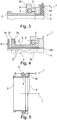
Fig. 5
einen Längsschnitt durch ein viertes Ausführungsbeispiel einer Kupplungsvorrichtung;
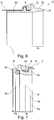
Fig. 6
einen Längsschnitt durch einen ersten Ring;
Fig. 7
einen Längsschnitt durch einen zweiten Ring;
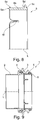
Fig. 8
einen Längsschnitt durch eine Entkupplungsvorrichtung;
Fig. 9
einen Längsschnitt durch ein fünftes Ausführungsbeispiel einer Kupplungsvorrichtung.
The drawing figures used to explain the embodiments show:
Fig. 1
a longitudinal section through a first embodiment of a coupling device;
Fig. 2
a detailed view of the coupling device according to FIG. 1 ;
Fig. 3
a second embodiment of a coupling device;
Fig. 4
a third embodiment of a coupling device;
Fig. 5
a longitudinal section through a fourth embodiment of a coupling device;
Fig. 6
a longitudinal section through a first ring;
Fig. 7
a longitudinal section through a second ring;
Fig. 8
a longitudinal section through a decoupling device;
Fig. 9
a longitudinal section through a fifth embodiment of a coupling device.

Grundsätzlich sind in den Zeichnungsfiguren gleiche Teile mit gleichen Bezugszeichen versehen.Basically, the same parts are provided with the same reference numerals in the drawing figures.

Wege zur Ausführung der ErfindungWays to carry out the invention

Figur 1 zeigt in einem Längsschnitt eine Kupplungsvorrichtung 1 zum wasserdichten Verbinden eines nur andeutungsweise dargestellten Handschuhs 10 mit einer nur andeutungsweise dargestellten Manschette 11 eines Trockentauchanzugs. Die Kupplungsvorrichtung 1 umfasst einen ersten Ring 2 sowie einen zweiten Ring 3, welche abdichtend an der Manschette 11 beziehungsweise dem Handschuh 10 befestigbar sind, wobei deren wasserdichte Befestigung nur schematisch und somit nicht im Detail dargestellt ist. Die Kupplungsvorrichtung 1 umfasst zudem einen Dichtring 4, wobei der erste Ring 2 eine aussen umfänglich verlaufende erste Nut 2b sowie eine senkrecht zur ersten Nut 2b verlaufende Längsachse L aufweist, und wobei der zweite Ring 3 eine innenumfänglich verlaufende zweite Nut 3b sowie eine senkrecht zur zweiten Nut 3b verlaufene Längsachse L aufweist. Der erste Ring 2 und der zweite Ring 3 sind derart ineinander steckbar, dass der erste Ring 2 und der zweite Ring 3 im Wesentlichen konzentrisch bezüglich der Längsachse L angeordnet werden, und dass der zweite Ring 3 in Verlaufsrichtung der Längsachse L in Richtung A zum ersten Ring 2 hin bewegt wird, wobei der Dichtring 4 in einer Sicherungsnut 2b des ersten Rings 2 angeordnet ist, und wobei der zweite Ring 3 über den Dichtring 4 geschoben wird, bis der Dichtring 4 in die Sicherungsnut 3b des zweiten Rings 3 zu liegen komm. Dadurch ersteht eine abdichtende Verbinden zwischen dem ersten Ring 2 und dem zweiten Ring 3, weil der Dichtring 4 gleichzeitig in der ersten Nut 2b und der zweiten Nut 3b verlaufend angeordnet ist, und dadurch eine wasserdichte Verbindung zwischen erstem und zweitem Ring 2,3 bewirkt. Der erste und der zweite Ring 2,3, der Dichtring 4 sowie die erste und die zweite Nut 2b, 3b sind vorzugsweise derart gegenseitig angepasst ausgestaltet, dass eine auf den ersten und zweiten Ring 2, 3 in Richtung der Längsachse L wirkende Kraft erforderlich ist, um den ersten und den zweiten Ring 2, 3 gegenseitig in Verlaufsrichtung der Längsachse L zu verschieben. Durch die Dicke und Elastizität des Dichtrings 4, und/oder durch die Tiefe und die Breite der erste Nut 2b und der zweiten Nut 3b, und/oder durch den gegenseitigen Abstand von erstem und zweitem Ring 2,3 in radialer Richtung kann zudem die Kraft bestimmt werden, welche erforderlich ist, um den ersten und den zweiten Ring 2,3 voneinander zu trennen durch ein gegenseitiges Verschieben in Richtung der Längsachse. FIG. 1 shows in a longitudinal section a coupling device 1 for watertight connection of a glove 10 only hinted illustrated with an only hinted cuff 11 of a dry suit. The coupling device 1 comprises a first ring 2 and a second ring 3, which are sealingly attachable to the sleeve 11 and the glove 10, wherein the waterproof fastening is only schematically and thus not shown in detail. The coupling device 1 also includes a Sealing ring 4, wherein the first ring 2 has an outer circumferentially extending first groove 2b and a perpendicular to the first groove 2b extending longitudinal axis L, and wherein the second ring 3 has an inner circumferential second groove 3b and a perpendicular to the second groove 3b extending longitudinal axis L. , The first ring 2 and the second ring 3 are plugged into one another such that the first ring 2 and the second ring 3 are arranged substantially concentrically with respect to the longitudinal axis L, and that the second ring 3 in the direction of the longitudinal axis L in the direction A to the first Ring 2 is moved towards, wherein the sealing ring 4 is arranged in a securing groove 2b of the first ring 2, and wherein the second ring 3 is pushed over the sealing ring 4 until the sealing ring 4 come to lie in the securing groove 3b of the second ring 3. This results in a sealing connection between the first ring 2 and the second ring 3, because the sealing ring 4 is arranged to extend simultaneously in the first groove 2b and the second groove 3b, and thereby causes a watertight connection between the first and second ring 2.3. The first and the second ring 2, 3, the sealing ring 4, and the first and the second groove 2b, 3b are preferably adapted to one another such that a force acting on the first and second rings 2, 3 in the direction of the longitudinal axis L is required to move the first and the second ring 2, 3 mutually in the direction of the longitudinal axis L. Due to the thickness and elasticity of the sealing ring 4, and / or by the depth and width of the first groove 2b and the second groove 3b, and / or by the mutual distance of the first and second ring 2,3 in the radial direction can also force be determined, which is required to separate the first and the second ring 2,3 from each other by a mutual displacement in the direction of the longitudinal axis.

Alternativ kann der zweite Ring 3 beispielsweise auch durch eine Schwenkbewegung mit dem ersten Ring 2 verbunden werden, beispielsweise indem der Dichtring 4 in der Sicherungsnut 2b des ersten Rings 2 angeordnet ist, indem die Sicherungsnut 3b des zweiten Rings 3 in Figur 1 beispielsweise oben auf den Dichtring 4 aufgelegt wird, indem der zweite Ring 3 bezüglich der Längsachse L des ersten Rings 2 verschwenkt gehalten wird, und indem der zweite Ring 3 um eine Drehachse gedreht wird, welche im Wesentlichen durch den Punkt der Auflage des zweiten Rings 3 auf dem Dichtring 4 bestimmt ist, wobei der zweite Ring 3 verschwenkt wird, bis der Dichtring 4 entlang des gesamten Umfangs in der Sicherungsnut 3b des zweiten Rings 3 zu liegen kommt. Durch ein derartiges Verschwenken des zweiten Rings 3 bezüglich des ersten Rings 2 können die beiden Ringe 2,3 auf einfache Weise abdichtend miteinander verbunden werden.Alternatively, the second ring 3 can be connected, for example, by a pivoting movement with the first ring 2, for example by the sealing ring 4 is arranged in the securing groove 2b of the first ring 2 by the securing groove 3b of the second ring 3 in FIG. 1 for example, is placed on top of the sealing ring 4 by the second ring 3 is pivoted relative to the longitudinal axis L of the first ring 2, and by the second ring 3 is rotated about an axis of rotation which is substantially through the point of the support of the second ring is determined on the sealing ring 4, wherein the second ring 3 is pivoted until the sealing ring 4 comes to lie along the entire circumference in the securing groove 3b of the second ring 3. By such a pivoting of the second ring 3 with respect to the first ring 2, the two rings 2,3 can be sealingly connected together in a simple manner.

Die Kupplungsvorrichtung 1 umfasst zudem eine in Längsrichtung L bewegliche, am ersten oder zweiten Ring 2,3 angreifende Entkupplungsvorrichtung 5, zum gegenseitigen Verschieben von erstem und zweitem Ring 2,3 in Längsrichtung L. Die beiden, zusammen mit dem Dichtring 4 eine abdichtende Verbindung bildenden ersten und zweiten Ringe 2,3 können beispielsweise derart getrennt werden, dass mit einem Finger eine Kraft B auf den zweiten Ring 3 ausgeübt wird, und dass mit einem weiteren Finger eine Gegenkraft C auf die Entkupplungsvorrichtung 5 ausgeübt wird, wobei bei genügend grosser, anliegender Kraft der erste Ring 2 bezüglich dem zweiten Ring 3 in Richtung A verschoben wird, bis der erste und der zweite Ring 2,3 vollständig voneinander getrennt sind. Die Entkupplungsvorrichtung 5 bewirkt, dass der Dichtring 4 durch die gegenseitige Bewegung der beiden Ringe 2,3 aus zumindest einer der Nuten 2b, 3b entfernt wird, sodass die beiden Ringe 2,3 danach leicht und vorzugsweise ohne zusätzliche Kraft voneinander entfernt werden können.The coupling device 1 also includes a movable in the longitudinal direction L, engaging the first or second ring 2.3 uncoupling device 5, for mutual displacement of first and second ring 2,3 in the longitudinal direction L. The two, together with the sealing ring 4 forming a sealing connection For example, first and second rings 2, 3 may be separated such that a force B is exerted on the second ring 3 with one finger, and that a counter force C is exerted on the decoupling device 5 with another finger, with a sufficiently large, adjacent one Force the first ring 2 is moved relative to the second ring 3 in the direction A until the first and the second ring 2.3 are completely separated from each other. The uncoupling device 5 causes the sealing ring 4 by the mutual movement of the two rings 2,3 from at least one the grooves 2b, 3b is removed, so that the two rings 2,3 can then be easily and preferably removed from each other without additional force.

Figur 2 zeigt in einer Detailansicht den oberen Teil der Kupplungsvorrichtung 1 gemäss Figur 1. Der erste Ring 2 umfasst einen ersten Kupplungsabschnitt 2a mit einer aussenumfänglich verlaufenden ersten Nut 2b, und umfasst einen Anschlag 2c, eine Auflagefläche 2d, ein radial vorstehendes Ringende 2e sowie eine Stirnseite 2f. Der zweite Ring 3 umfasst einen zweiten Kupplungsabschnitt 3a mit einer innenumfänglich verlaufenden zweiten Nut 3b, und umfasst einen Anschlag 3c, eine Aussenfläche 3d sowie ein radial vorstehendes Ringende 3e. Die Entkupplungsvorrichtung 5 umfasst ein hohlzylinderförmiges Verbindungsteil 5b, welches in Längsrichtung L verschiebbar im zweiten Ring 3 gelagert ist. Das Verbindungsteil 5b weist am einen Ende ein in radialer Richtung vorstehendes Betätigungsteil 5c auf, welches zudem einen Anschlag 5d ausbildet, und weist am anderen Ende eine Stossseite 5a auf. Die Entkupplungsvorrichtung 5 und der erste Ring 2 sind derart gegenseitig angepasst ausgestaltet, dass die Stossseite 5a in Längsrichtung L gegenüber der Stirnseite 2f zu liegen kommt, sodass die Entkupplungsvorrichtung 5 in Längsrichtung L eine Stosskraft auf den ersten Ring 2 ausüben kann, und diesen in Richtung A verschieben kann. FIG. 2 shows in a detailed view of the upper part of the coupling device 1 according to FIG. 1 , The first ring 2 comprises a first coupling portion 2a with an outer circumferential first groove 2b, and comprises a stop 2c, a bearing surface 2d, a radially projecting annular end 2e and an end face 2f. The second ring 3 comprises a second coupling section 3a with an inner circumferential second groove 3b, and comprises a stop 3c, an outer surface 3d and a radially projecting annular end 3e. The uncoupling device 5 comprises a hollow-cylindrical connecting part 5b, which is mounted so as to be displaceable in the longitudinal direction L in the second ring 3. The connecting part 5b has at one end a radially projecting actuating part 5c, which also forms a stop 5d, and has at the other end on a shock side 5a. The uncoupling device 5 and the first ring 2 are designed to be mutually adapted such that the impact side 5a comes to lie in the longitudinal direction L opposite the end face 2f, so that the uncoupling device 5 can exert a shock force on the first ring 2 in the longitudinal direction L, and this in the direction A can move.

Figur 3 zeigt ein Detail eines weiteren Ausführungsbeispiels einer Kupplungsvorrichtung 1. Zwischen dem zweiten Ring 3 und dem Betätigungsteil 5c ist ein Federelement 6 angeordnet, beispielsweise ein ringförmiges Schaumstoffteil oder ein leicht komprimierbarer O-Ring zum Beispiel aus Silikon, welches eine Rückstellkraft auf die Entkupplungsvorrichtung 5 bewirken kann, sodass die Entkupplungsvorrichtung 5, wie in Figur 3 dargestellt, in einer Grundstellung beispielsweise beabstandet bezüglich dem ersten Ring 2 angeordnet sein kann. Im Ausführungsbeispiel gemäss Figur 3 sind zudem das Betätigungsteil 3f sowie das Betätigungsteil 5c in radialer Richtung besonders weit nach oben verlaufend ausgestaltet, sodass an den Stirnseiten eine besonders grosse Fläche zur Verfügung steht, über welche, beispielsweise mit einer Hand, die Kräfte B und C angelegt werden können, um die Kupplungsvorrichtung 1 zu öffnen. FIG. 3 shows a detail of a further embodiment of a coupling device 1. Between the second ring 3 and the actuating part 5c, a spring element 6 is arranged, for example, an annular foam part or an easily compressible O-ring, for example made of silicone, which has a restoring force on the Uncoupling device 5 can cause, so that the decoupling device 5, as in FIG. 3 represented, for example, in a basic position at a distance from the first ring 2 may be arranged. In the embodiment according to FIG. 3 In addition, the actuating part 3f and the actuating part 5c in the radial direction are designed to extend particularly far upward, so that at the end faces a particularly large area is available over which, for example, with one hand, the forces B and C can be applied to the Coupling device 1 to open.

Im Unterschied zu der in Figur 3 dargestellten Kupplungsvorrichtung 1 ist bei der in Figur 4 dargestellten Kupplungsvorrichtung 1 die Entkupplungsvorrichtung 5 durch den ersten Ring 2 in Längsrichtung L geführt, wobei der erste Ring 2 ein Betätigungsteil 2f und die Entkupplungsvorrichtung 5 ein gegenüberliegen angeordnetes Betätigungsteil 5c aufweist, sodass über die angelegten Kräfte B und C über die Stossseite 5a und über eine Stirnseite 3g eine Kraft auf den zweiten Ring 3 ausgeübt wird, um die Kupplungsvorrichtung 1 zu öffnen.Unlike the in FIG. 3 illustrated coupling device 1 is in the in FIG. 4 1, the decoupling device 5 is guided through the first ring 2 in the longitudinal direction L, wherein the first ring 2, an actuating part 2f and the decoupling device 5 an oppositely disposed actuating part 5c has, so over the applied forces B and C on the impact side 5a and a End face 3g a force is exerted on the second ring 3 to open the coupling device 1.

Figur 5 zeigt ein weiteres Ausführungsbeispiel einer Kupplungsvorrichtung 1, deren Entkupplungsvorrichtung 5, im Unterschied zu dem in Figur 1 dargestellten Ausführungsbeispiel, nicht rotationssymmetrisch bezüglich der Längsachse L ausgestaltet ist, und ein Betätigungsteil 5c umfasst, das sich, je nach Ausführungsform, über einen Bereich zwischen 10° und 180° erstrecken kann, sodass nur in diesem Bereich die Kraft C über das Betätigungsteil 5c auf angenehme Weise in die Entkupplungsvorrichtung 5 eingeleitet werden kann. FIG. 5 shows a further embodiment of a coupling device 1, the decoupling device 5, in contrast to the in FIG. 1 illustrated embodiment, is not configured rotationally symmetrical with respect to the longitudinal axis L, and an actuating part 5c includes, which may extend over a range between 10 ° and 180 °, depending on the embodiment, so that only in this area, the force C on the operating part 5c on pleasant way in the decoupling device 5 can be initiated.

Die Figuren 6 bis 9 zeigen in Längsschnitten ein weiteres Ausführungsbeispiel einer erfindungsgemässen Vorrichtung 1 zum wasserdichten Verbinden eines Handschuhs 10 mit einer Manschette 11 eines Trockentauchanzugs, wobei die Figur 6 den ersten Ring 2, die Figur 7 den zweiten Ring 3, die Figur 8 die Entkupplungsvorrichtung 5 und Figur 9 die zusammengebaute Vorrichtung 1 zeigen. Der erste Ring 2 umfasst die aussen umlaufende Nut 2b, und umfasst den ersten Kupplungsabschnitt 2a mit Stirnseite 2f, Anschlag 2c und Auflagefläche 2d. Zudem ist andeutungsweise die Manschette 11 dargestellt, welche über einen umlaufenden Ring 9 wasserdicht mit dem ersten Ring 2 verbunden ist. Der zweite Ring 3 umfasst eine innen umlaufende Nut 3b, in welcher andeutungsweise der Dichtring 4, ein O-Ring, dargestellt ist. Der zweite Ring 3 umfasst einen zweiten Kupplungsabschnitt 3a mit einem Anschlag 3c, sowie eine Auflagefläche 3d und ein Ringende 3e. Zudem ist andeutungsweise der Handschuh 10 dargestellt, welcher über einen umlaufenden Ring 9 wasserdicht mit dem zweiten Ring 3 verbunden ist. Der zweite Ring 3 umfasst zudem einen Halteabschnitt 3k, mit einem sich verjüngenden Eingangsabschnitt 3g, einem parallel zur Längsachse L verlaufenden Zwischenabschnitt 3h und einem sich erweiternden Endabschnitt 3i. Die Entkupplungsvorrichtung 5 umfasst ein parallel zur Längsachse L verlaufendes, ringförmiges Verbindungsteil 5b, das einerseits an der Stossseite 5a endet, und andererseits am Betätigungsteil 5c endet. Das Betätigungsteil 5c bildet zudem einen Anschlag 5d. Zudem umfasst die Entkupplungsvorrichtung 5 ein in radialer Richtung über das Verbindungsteil 5b vorstehendes Halteteil 5e. Zudem umfasst die ringförmige Entkupplungsvorrichtung 5 in einer vorteilhaften Ausgestaltung eine Mehrzahl von in Umfangsrichtung gegenseitig beabstandeten Ausnehmungen 5f, welche insbesondere dazu dienen, dem in Umfangsrichtung verlaufendem Halteteil 5e in bezüglich der Längsachse L radialer Richtung federnde Eigenschaften zu verleihen. Wie in Figur 9 dargestellt kann das Verbindungsteil 5b in den Zwischenabschnitt 3h des zweiten Rings 3 eingeführt werden, wobei das Halteteil 5e im entspannten Zustand einen grösseren Durchmesser aufweist als der Zwischenabschnitt 3h, sodass die Entkupplungsvorrichtung 5 in Längsrichtung L beweglich im zweiten Ring 3 gehalten ist.The FIGS. 6 to 9 show in longitudinal sections a further embodiment of an inventive device 1 for watertight connection of a glove 10 with a sleeve 11 of a dry suit, wherein the FIG. 6 the first ring 2, the FIG. 7 the second ring 3, the FIG. 8 the decoupling device 5 and FIG. 9 show the assembled device 1. The first ring 2 comprises the outer circumferential groove 2b, and comprises the first coupling portion 2a with end face 2f, stop 2c and bearing surface 2d. In addition, hinted cuff 11 is shown, which is connected via a circumferential ring 9 waterproof to the first ring 2. The second ring 3 comprises an inner circumferential groove 3b, in which hinted the sealing ring 4, an O-ring, is shown. The second ring 3 comprises a second coupling section 3a with a stop 3c, as well as a support surface 3d and a ring end 3e. In addition, suggestively the glove 10 is shown, which is connected via a circumferential ring 9 waterproof to the second ring 3. The second ring 3 further comprises a holding section 3k, having a tapered input section 3g, an intermediate section 3h extending parallel to the longitudinal axis L, and a widening end section 3i. The uncoupling device 5 comprises a ring-shaped connecting part 5b running parallel to the longitudinal axis L, which terminates on the one hand on the impact side 5a and on the other hand ends on the actuating part 5c. The actuating part 5c also forms a stop 5d. In addition, the uncoupling device 5 comprises a holding part 5e projecting in the radial direction over the connecting part 5b. In addition, the annular decoupling device 5 comprises in an advantageous embodiment a plurality of circumferentially mutually spaced recesses 5f, which serve in particular to give the circumferentially extending holding part 5e in the radial direction with respect to the longitudinal axis L resilient properties. As in FIG. 9 the connecting part 5b can be introduced into the intermediate section 3h of the second ring 3, wherein the holding part 5e has a larger diameter in the relaxed state than the intermediate section 3h, so that the uncoupling device 5 is held movably in the longitudinal direction L in the second ring 3.

Das erfindungsgemässe Verfahren zum wasserdichten Verbinden des Handschuhs 10 mit der Manschette 11 des Trockentauchanzugs erfolgt vorzugsweise derart, dass der erste Ring 2, der zweite Ring 3 und der Dichtring 4 derart ineinander gesteckt werden, dass der Dichtring 4 zum abdichtenden Verbinden des ersten Rings 2 mit dem zweiten Ring 3 gleichzeitig in der erste Nut 2b und der zweiten Nut 3b verlaufend angeordnet wird, und dass zum Trennen der abdichtenden Verbindung mit der Entkupplungsvorrichtung 5 der erste Ring 2 derart bezüglich des zweiten Rings 3 in Längsrichtung L verschoben wird, dass der Dichtring 4 aus zumindest der erste Nut 2b oder der zweiten Nut 3b entfernt wird, und dadurch die abdichtende Verbindung aufgehoben wird.The inventive method for watertight connection of the glove 10 with the sleeve 11 of the dry suit is preferably such that the first ring 2, the second ring 3 and the sealing ring 4 are inserted into one another such that the sealing ring 4 for sealingly connecting the first ring 2 with the second ring 3 is arranged to extend simultaneously in the first groove 2b and the second groove 3b, and that for separating the sealing connection with the uncoupling device 5, the first ring 2 is displaced with respect to the second ring 3 in the longitudinal direction L that the sealing ring is removed from at least the first groove 2b or the second groove 3b, and thereby the sealing connection is released.

Vorteilhafterweise wird am zweiten Ring 3 eine in Längsrichtung L wirkende erste Kraft B angelegt, und wird an der Entkupplungsvorrichtung 5 eine in entgegengesetzter Längsrichtung L wirkende Gegenkraft C angelegt wird, sodass der erste Ring 2 durch die einwirkende Entkupplungsvorrichtung 5 in entgegengesetzter Längsrichtung bezüglich dem zweiten Ring 3 verschoben wird, zumindest bis die abdichtende Verbindung zwischen Dichtring 4 sowie erstem und zweitem Ring 2,3 aufgehoben ist.Advantageously, a first force B acting in the longitudinal direction L is applied to the second ring 3, and a counterforce C acting in the opposite longitudinal direction L is applied to the decoupling device 5, so that the first ring 2 by the acting decoupling device 5 in the opposite longitudinal direction with respect to the second ring 3 is moved, at least until the sealing connection between the sealing ring 4 and the first and second ring 2.3 is repealed.

Claims (11)

Vorrichtung (1) zum wasserdichten Verbinden eines Handschuhs (10) mit einer Manschette (11) eines Trockentauchanzugs, umfassend: einen ersten Ring (2), der abdichtend an der Manschette (11) oder dem Handschuh (10) befestigbar ist, einen zweiten Ring (3), der abdichtend am Handschuh (10) oder an der Manschette (15) befestigbar ist, sowie einen Dichtring (4), wobei der erste Ring (2) eine aussen umfänglich verlaufende erste Nut (2b) sowie eine senkrecht zur ersten Nut (2b) verlaufende Längsachse (L) aufweist, und wobei der zweite Ring (3) eine innenumfänglich verlaufende zweite Nut (3b) sowie eine senkrecht zur zweiten Nut (3b) verlaufene Längsachse (L) aufweist, und wobei der erste Ring (2) und der zweite Ring (3) derart ineinander steckbar sind, dass der Dichtring (4) zum abdichtenden Verbinden des ersten Rings (2) mit dem zweiten Ring (3) gleichzeitig in der erste Nut (2b) und der zweiten Nut (3b) verlaufend angeordnet ist, dadurch gekennzeichnet, dass die Vorrichtung zudem eine in Längsrichtung (L) bewegliche, am ersten oder zweiten Ring (2,3) angreifende Entkupplungsvorrichtung (5) umfasst, zum gegenseitigen Verschieben von erstem und zweitem Ring (2,3) in Längsrichtung (L). Device (1) for watertight connection of a glove (10) to a cuff (11) of a dry suit, comprising: a first ring (2) which is sealingly attachable to the sleeve (11) or the glove (10), a second ring (3) sealingly attachable to the glove (10) or cuff (15), and a sealing ring (4), wherein the first ring (2) has a first circumferentially extending first groove (2b) and a longitudinal axis (L) extending perpendicularly to the first groove (2b), and wherein the second ring (3) has a second groove (3b) running on the inside and one has longitudinal axis (L) running perpendicular to the second groove (3b), and wherein the first ring (2) and the second ring (3) are insertable into one another such that the sealing ring (4) for sealingly connecting the first ring (2) to the second ring (3) simultaneously in the first groove (2b) and the second groove (3b) is arranged to run, characterized in that the device also has a longitudinal (L) movable, on the first or second ring (2,3) engaging decoupling device (5), for mutual displacement of the first and second ring (2,3) in the longitudinal direction (L). Vorrichtung nach Anspruch 1, dadurch gekennzeichnet, dass die Entkupplungsvorrichtung (5) konzentrisch zur Längsachse (L) angeordnet ist.Apparatus according to claim 1, characterized in that the decoupling device (5) is arranged concentrically to the longitudinal axis (L). Vorrichtung nach einem der vorhergehenden Ansprüchen, dadurch gekennzeichnet, dass die Entkupplungsvorrichtung (5) ein in Längsrichtung (L) über den ersten oder den zweiten Ring (2,3) vorstehendes Betätigungsteil (5c) aufweist.Device according to one of the preceding claims, characterized in that the decoupling device (5) in the longitudinal direction (L) via the first or the second ring (2,3) projecting actuating part (5c). Vorrichtung nach Anspruch 3, dadurch gekennzeichnet, dass die Entkupplungsvorrichtung (5) ein mit dem ersten oder dem zweiten Ring (2,3) zusammenwirkendes Federelement (6) aufweist, welche die Entkupplungsvorrichtung (5) in Längsrichtung (L) in einer Grundstellung hält.Device according to claim 3, characterized in that the decoupling device (5) has a spring element (6) cooperating with the first or the second ring (2,3), which holds the decoupling device (5) in the longitudinal direction (L) in a basic position. Vorrichtung nach einem der vorhergehenden Ansprüche, dadurch gekennzeichnet, dass die Entkupplungsvorrichtung (5) eine zum ersten Ring (2) hin ausgerichtete Stossseite (5a) aufweist, dass der erste Ring (2) eine zur Stossseite (5a) hin ausgerichtete Stirnseite (2g) aufweist, und dass die Entkupplungsvorrichtung (5) in Längsrichtung (L) verschiebbar im zweiten Ring (3) gelagert ist, um durch eine Bewegung der Entkupplungsvorrichtung (5) in Längsrichtung (L) ein gegenseitiges Verschieben des ersten Rings (2) bezüglich des zweiten Rings (3) zu bewirken.Device according to one of the preceding claims, characterized in that the uncoupling device (5) has a shock side (5a) oriented towards the first ring (2), in that the first ring (2) has an end face (2g) directed towards the impact side (5a). and in that the decoupling device (5) is displaceably mounted in the longitudinal direction (L) in the second ring (3) so as to displace the first ring (2) relative to the second one by movement of the decoupling device (5) in the longitudinal direction (L) To cause ring (3). Vorrichtung nach einem der Ansprüche 1 bis 4, dadurch gekennzeichnet, dass die Entkupplungsvorrichtung (5) eine zum zweiten Ring (3) hin ausgerichtete Stossseite (5a) aufweist, dass der zweite Ring (3) eine zur Stossseite (5a) hin ausgerichtete Stirnseite (3g) aufweist, und dass die Entkupplungsvorrichtung (5) in Längsrichtung (L) verschiebbar im ersten Ring (2) angeordnet ist, um durch eine Bewegung der Entkupplungsvorrichtung (5) in Längsrichtung (L) ein gegenseitiges Verschieben des ersten Rings (2) bezüglich des zweiten Rings (3) zu bewirken.Device according to one of claims 1 to 4, characterized in that the decoupling device (5) has a second ring (3) directed towards the shock side (5a), that the second ring (3) to the shock side (5a) directed towards end face ( 3g), and in that the decoupling device (5) is arranged displaceably in the longitudinal direction (L) in the first ring (2) so as to move the first ring (2) relative to one another by a movement of the decoupling device (5) in the longitudinal direction (L) to effect the second ring (3). Vorrichtung nach einem der vorhergehenden Ansprüche, dadurch gekennzeichnet, dass die Entkupplungsvorrichtung (5) einen Anschlag (5d) umfasst, welcher die maximale Bewegung der Entkupplungsvorrichtung (5) in Längsrichtung (L) bezüglich dem ersten oder zweiten Ring (2,3) begrenzt.Device according to one of the preceding claims, characterized in that the uncoupling device (5) comprises a stop (5d) which limits the maximum movement of the uncoupling device (5) in the longitudinal direction (L) with respect to the first or second ring (2,3). Vorrichtung nach einem der vorhergehenden Ansprüche, dadurch gekennzeichnet, dass die Entkupplungsvorrichtung (5) in Längsrichtung (L) zumindest abschnittweise innerhalb des ersten Rings (2) oder des zweiten Rings (3) verläuft, und dass die Entkupplungsvorrichtung (5) in Längsrichtung (L) beabstandet einen ersten Anschlag (5d) und einen zweiten Anschlag (5e) umfasst, welcher mit dem ersten Ring (2) oder dem zweiten Ring (3) derart zusammenwirken, dass die Bewegungsfreiheit der Entkupplungsvorrichtung (5) in Längsrichtung (L) bezüglich dem ersten oder zweiten Ring (2,3) begrenzt ist.Device according to one of the preceding claims, characterized in that the decoupling device (5) extends in the longitudinal direction (L) at least in sections within the first ring (2) or the second ring (3), and in that the decoupling device (5) in the longitudinal direction (L ) spaced apart a first stop (5d) and a second stop (5e) which cooperate with the first ring (2) or the second ring (3) such that the freedom of movement of the decoupling device (5) in the longitudinal direction (L) with respect first or second ring (2,3) is limited. Verfahren zum wasserdichten Verbinden eines Handschuhs (10) mit einer Manschette (11) eines Trockentauchanzugs,: wobei ein erster Ring (2) abdichtend an der Manschette (11) befestigt ist, wobei ein zweiter Ring (7) abdichtend am Handschuh (10) befestigt ist, wobei der erste Ring (2) eine aussen umfänglich verlaufende erste Nut (2b) und der zweite Ring (3) eine innenumfänglich verlaufende zweite Nut (3b) umfasst, und wobei der erste Ring (2), der zweite Ring (3) und ein Dichtring (4) derart in einer Längsrichtung (L) ineinander gesteckt werden, dass der Dichtring (4) zum abdichtenden Verbinden des ersten Rings (2) mit dem zweiten Ring (3) gleichzeitig in der erste Nut (2b) und der zweiten Nut (3b) verlaufend angeordnet wird, dadurch gekennzeichnet, dass zum Trennen der abdichtenden Verbindung mit einer Entkupplungsvorrichtung (5) der erste Ring (2) derart bezüglich des zweiten Rings (3) in Längsrichtung (L) verschoben wird, dass der Dichtring (4) aus zumindest der erste Nut (2b) oder der zweiten Nut (3b) entfernt wird, und dadurch die abdichtende Verbindung aufgehoben wird. Method for watertight connection of a glove (10) to a cuff (11) of a dry suit ,: wherein a first ring (2) is sealingly attached to the collar (11), wherein a second ring (7) is sealingly attached to the glove (10), wherein the first ring (2) comprises an outwardly circumferentially extending first groove (2b) and the second ring (3) comprises an internally extending second groove (3b), and wherein the first ring (2), the second ring (3) and a Sealing ring (4) in such a longitudinal direction (L) are inserted into each other, that the sealing ring (4) for sealingly connecting the first ring (2) with the second ring (3) simultaneously in the first groove (2b) and the second groove ( 3b) is arranged running, characterized in that for separating the sealing connection with a decoupling device (5) of the first ring (2) with respect to the second ring (3) in the longitudinal direction (L) is displaced, that the sealing ring (4) at least the first groove (2b) or the second groove (3b) is removed, and thereby the sealing connection is released. Verfahren nach Anspruch 9, dadurch gekennzeichnet, dass am zweiten Ring (3) eine in Längsrichtung (L) wirkende Kraft angelegt wird, dass an der Entkupplungsvorrichtung (5) eine in entgegengesetzter Längsrichtung (L1) wirkende Kraft angelegt wird, und dass der erste Ring (2) durch die einwirkende Entkupplungsvorrichtung (5) in entgegengesetzter Längsrichtung (L1) bezüglich dem zweiten Ring (3) verschoben wird, zumindest bis die abdichtende Verbindung zwischen Dichtring (4) sowie erstem und zweitem Ring (2,3) aufgehoben ist.Method according to Claim 9, characterized in that a force acting in the longitudinal direction (L) is applied to the second ring (3), that a force acting in the opposite longitudinal direction (L1) is applied to the decoupling device (5), and that the first ring (2) is displaced by the acting decoupling device (5) in the opposite longitudinal direction (L1) with respect to the second ring (3), at least until the sealing connection between Sealing ring (4) and the first and second ring (2,3) is repealed. Trockentauchanzug umfassend eine Vorrichtung nach einem der Ansprüche 1 bis 8.Dry suit comprising a device according to one of claims 1 to 8.
EP17184959.9A 2017-08-04 2017-08-04 Device and method for water-sealing the connection of a glove with a cuff Withdrawn EP3437502A1 (en)

Priority Applications (2)

Application Number Priority Date Filing Date Title
EP17184959.9A EP3437502A1 (en) 2017-08-04 2017-08-04 Device and method for water-sealing the connection of a glove with a cuff
DE202018101809.4U DE202018101809U1 (en) 2017-08-04 2018-04-03 Device for watertight connection of a glove with a cuff

Applications Claiming Priority (1)

Application Number Priority Date Filing Date Title
EP17184959.9A EP3437502A1 (en) 2017-08-04 2017-08-04 Device and method for water-sealing the connection of a glove with a cuff

Publications (1)

Publication Number Publication Date
EP3437502A1 true EP3437502A1 (en) 2019-02-06

Family

ID=59581733

Family Applications (1)

Application Number Title Priority Date Filing Date
EP17184959.9A Withdrawn EP3437502A1 (en) 2017-08-04 2017-08-04 Device and method for water-sealing the connection of a glove with a cuff

Country Status (2)

Country Link
EP (1) EP3437502A1 (en)
DE (1) DE202018101809U1 (en)

Cited By (1)

* Cited by examiner, † Cited by third party
Publication number Priority date Publication date Assignee Title
EP4227203A1 (en) 2022-02-09 2023-08-16 SplashLight GmbH Device for the waterproof connection of a glove with a cuff of a dry suit

Citations (5)

* Cited by examiner, † Cited by third party
Publication number Priority date Publication date Assignee Title
EP0406139A2 (en) * 1989-06-26 1991-01-02 Matisec S.A. Connector for tightly sealing gloves and boots to protective apparel
DE9415682U1 (en) * 1994-09-28 1994-12-08 Stief Wolfgang One-handed dry diving glove
DE19701343C2 (en) 1997-01-16 2003-07-03 Euwa Sport Roland Schnell Lauf Device for watertight connection of a glove to a sleeve cuff of a dry suit
US6715159B2 (en) 2001-05-29 2004-04-06 Her Majesty The Queen In Right Of Canada As Represented By The Minister Of Natural Resources Angularly disengageable glove-to-cuff connection apparatus
DE102008044853A1 (en) * 2008-01-28 2009-07-30 Dirk Losch Connecting device for connecting a protective glove to a protective suit, in particular to a dry suit

Patent Citations (5)

* Cited by examiner, † Cited by third party
Publication number Priority date Publication date Assignee Title
EP0406139A2 (en) * 1989-06-26 1991-01-02 Matisec S.A. Connector for tightly sealing gloves and boots to protective apparel
DE9415682U1 (en) * 1994-09-28 1994-12-08 Stief Wolfgang One-handed dry diving glove
DE19701343C2 (en) 1997-01-16 2003-07-03 Euwa Sport Roland Schnell Lauf Device for watertight connection of a glove to a sleeve cuff of a dry suit
US6715159B2 (en) 2001-05-29 2004-04-06 Her Majesty The Queen In Right Of Canada As Represented By The Minister Of Natural Resources Angularly disengageable glove-to-cuff connection apparatus
DE102008044853A1 (en) * 2008-01-28 2009-07-30 Dirk Losch Connecting device for connecting a protective glove to a protective suit, in particular to a dry suit

Cited By (1)

* Cited by examiner, † Cited by third party
Publication number Priority date Publication date Assignee Title
EP4227203A1 (en) 2022-02-09 2023-08-16 SplashLight GmbH Device for the waterproof connection of a glove with a cuff of a dry suit

Also Published As

Publication number Publication date
DE202018101809U1 (en) 2018-04-17

Similar Documents

Publication Publication Date Title
DE4309992C2 (en) Connector for pipes with a small diameter
CH678884A5 (en)
DE1809166B2 (en) Coupling unit for flow systems
DE602004004232T2 (en) pipe connection
DE10032010C1 (en) Connection fitting for a pipe etc. through a housing wall has a division near the angled support surface for the limit ring to allow for large wall thickness differences
DE2652207A1 (en) QUICK PIPE COUPLING
DE2530863A1 (en) COUPLING, ESPECIALLY FOR CONNECTING PIPES
DE2042938A1 (en) Pipe connection, especially for risers of underwater boreholes
DE1775302B2 (en) HOSE COUPLING
DE102011118099A1 (en) Device for connecting two line sections
DE102008018426A1 (en) coupling device
DE102011085398A1 (en) connecting unit
DE1213170B (en) Quick-release fastener
EP3263202B1 (en) Withdrawal system and withdrawal aid for a separation element
DE2822259C2 (en) Quick coupling for tubular lines, in particular for liquids
EP3250147B1 (en) Scanning body system for determining a position and orientation of a dental implant
DE2105108B2 (en) Slide-in pipe coupling
EP3437502A1 (en) Device and method for water-sealing the connection of a glove with a cuff
DE2262508B2 (en) DETACHABLE CONNECTION ARRANGEMENT FOR A PIPE FITTING AND A HOSE
DE1791013C2 (en) Coupling for connecting a dental handpiece or angle piece to an electric drive motor designed as a miniature motor
CH581273A5 (en) Snap connection between hose ends - has inner and outer sleeves with O-ring seal and finger with ridge and groove
DE102012219058A1 (en) Quick nut
WO2015090675A1 (en) Sealing plug for a quick connect coupling
DE2851661A1 (en) Pipe coupling with wedging contractible ring - is disengaged by moving pipes manually inward and inserting thin half circular sleeve tool
EP3824143B1 (en) Wall mounting with riser rail

Legal Events

Date Code Title Description
PUAI Public reference made under article 153(3) epc to a published international application that has entered the european phase

Free format text: ORIGINAL CODE: 0009012

STAA Information on the status of an ep patent application or granted ep patent

Free format text: STATUS: THE APPLICATION HAS BEEN PUBLISHED

AK Designated contracting states

Kind code of ref document: A1

Designated state(s): AL AT BE BG CH CY CZ DE DK EE ES FI FR GB GR HR HU IE IS IT LI LT LU LV MC MK MT NL NO PL PT RO RS SE SI SK SM TR

AX Request for extension of the european patent

Extension state: BA ME

STAA Information on the status of an ep patent application or granted ep patent

Free format text: STATUS: REQUEST FOR EXAMINATION WAS MADE

17P Request for examination filed

Effective date: 20190805

RBV Designated contracting states (corrected)

Designated state(s): AL AT BE BG CH CY CZ DE DK EE ES FI FR GB GR HR HU IE IS IT LI LT LU LV MC MK MT NL NO PL PT RO RS SE SI SK SM TR

STAA Information on the status of an ep patent application or granted ep patent

Free format text: STATUS: EXAMINATION IS IN PROGRESS

17Q First examination report despatched

Effective date: 20220804

STAA Information on the status of an ep patent application or granted ep patent

Free format text: STATUS: THE APPLICATION IS DEEMED TO BE WITHDRAWN

18D Application deemed to be withdrawn

Effective date: 20221215