EP3436660B1 - Analyse modale d'opération de fond de trou - Google Patents
Analyse modale d'opération de fond de trou Download PDFInfo
- Publication number
- EP3436660B1 EP3436660B1 EP17776644.1A EP17776644A EP3436660B1 EP 3436660 B1 EP3436660 B1 EP 3436660B1 EP 17776644 A EP17776644 A EP 17776644A EP 3436660 B1 EP3436660 B1 EP 3436660B1
- Authority
- EP
- European Patent Office
- Prior art keywords
- drill string
- drilling
- modal
- excitation
- mathematical model
- Prior art date
- Legal status (The legal status is an assumption and is not a legal conclusion. Google has not performed a legal analysis and makes no representation as to the accuracy of the status listed.)
- Active
Links
- 238000004458 analytical method Methods 0.000 title description 14
- 238000005553 drilling Methods 0.000 claims description 86
- 238000000034 method Methods 0.000 claims description 33
- 230000005284 excitation Effects 0.000 claims description 30
- 239000012530 fluid Substances 0.000 claims description 17
- 238000005259 measurement Methods 0.000 claims description 16
- 238000013016 damping Methods 0.000 claims description 14
- 238000013178 mathematical model Methods 0.000 claims description 10
- 230000000149 penetrating effect Effects 0.000 claims description 6
- 230000004044 response Effects 0.000 claims description 4
- 238000009826 distribution Methods 0.000 claims description 3
- 230000015572 biosynthetic process Effects 0.000 description 16
- 238000005755 formation reaction Methods 0.000 description 16
- 239000011159 matrix material Substances 0.000 description 8
- 230000005251 gamma ray Effects 0.000 description 5
- 230000035515 penetration Effects 0.000 description 5
- 239000003795 chemical substances by application Substances 0.000 description 4
- 238000004891 communication Methods 0.000 description 4
- 230000000694 effects Effects 0.000 description 4
- 230000001133 acceleration Effects 0.000 description 3
- 239000007789 gas Substances 0.000 description 3
- 238000004519 manufacturing process Methods 0.000 description 3
- 230000003287 optical effect Effects 0.000 description 3
- 230000008569 process Effects 0.000 description 3
- CURLTUGMZLYLDI-UHFFFAOYSA-N Carbon dioxide Chemical compound O=C=O CURLTUGMZLYLDI-UHFFFAOYSA-N 0.000 description 2
- 230000000712 assembly Effects 0.000 description 2
- 238000000429 assembly Methods 0.000 description 2
- 238000005452 bending Methods 0.000 description 2
- 230000008859 change Effects 0.000 description 2
- 238000005520 cutting process Methods 0.000 description 2
- 238000009795 derivation Methods 0.000 description 2
- 238000013461 design Methods 0.000 description 2
- 238000010586 diagram Methods 0.000 description 2
- 230000006870 function Effects 0.000 description 2
- 229930195733 hydrocarbon Natural products 0.000 description 2
- 150000002430 hydrocarbons Chemical class 0.000 description 2
- 239000000463 material Substances 0.000 description 2
- 239000000203 mixture Substances 0.000 description 2
- 239000003607 modifier Substances 0.000 description 2
- 238000012544 monitoring process Methods 0.000 description 2
- 230000035699 permeability Effects 0.000 description 2
- 238000012545 processing Methods 0.000 description 2
- 239000007787 solid Substances 0.000 description 2
- -1 steam Substances 0.000 description 2
- 230000000638 stimulation Effects 0.000 description 2
- 238000003860 storage Methods 0.000 description 2
- XLYOFNOQVPJJNP-UHFFFAOYSA-N water Substances O XLYOFNOQVPJJNP-UHFFFAOYSA-N 0.000 description 2
- 239000004215 Carbon black (E152) Substances 0.000 description 1
- 238000005481 NMR spectroscopy Methods 0.000 description 1
- 238000010793 Steam injection (oil industry) Methods 0.000 description 1
- 239000002253 acid Substances 0.000 description 1
- 150000007513 acids Chemical class 0.000 description 1
- 230000009286 beneficial effect Effects 0.000 description 1
- 230000008901 benefit Effects 0.000 description 1
- 239000012267 brine Substances 0.000 description 1
- 238000004422 calculation algorithm Methods 0.000 description 1
- 238000004364 calculation method Methods 0.000 description 1
- 239000003990 capacitor Substances 0.000 description 1
- 229910002092 carbon dioxide Inorganic materials 0.000 description 1
- 239000001569 carbon dioxide Substances 0.000 description 1
- 239000004568 cement Substances 0.000 description 1
- 238000004140 cleaning Methods 0.000 description 1
- 238000004590 computer program Methods 0.000 description 1
- 238000005094 computer simulation Methods 0.000 description 1
- 239000004020 conductor Substances 0.000 description 1
- 238000005260 corrosion Methods 0.000 description 1
- 238000010168 coupling process Methods 0.000 description 1
- 238000007405 data analysis Methods 0.000 description 1
- 238000013480 data collection Methods 0.000 description 1
- 238000000354 decomposition reaction Methods 0.000 description 1
- 230000009365 direct transmission Effects 0.000 description 1
- 238000006073 displacement reaction Methods 0.000 description 1
- 239000003995 emulsifying agent Substances 0.000 description 1
- 238000011156 evaluation Methods 0.000 description 1
- 230000002349 favourable effect Effects 0.000 description 1
- 238000009472 formulation Methods 0.000 description 1
- 230000036541 health Effects 0.000 description 1
- 230000006872 improvement Effects 0.000 description 1
- 230000006698 induction Effects 0.000 description 1
- 238000002347 injection Methods 0.000 description 1
- 239000007924 injection Substances 0.000 description 1
- 238000005304 joining Methods 0.000 description 1
- 239000007788 liquid Substances 0.000 description 1
- 238000012986 modification Methods 0.000 description 1
- 230000004048 modification Effects 0.000 description 1
- 230000010355 oscillation Effects 0.000 description 1
- 230000002093 peripheral effect Effects 0.000 description 1
- 239000000700 radioactive tracer Substances 0.000 description 1
- 239000011435 rock Substances 0.000 description 1
- 238000005070 sampling Methods 0.000 description 1
- 230000009919 sequestration Effects 0.000 description 1
- 238000004088 simulation Methods 0.000 description 1
- HPALAKNZSZLMCH-UHFFFAOYSA-M sodium;chloride;hydrate Chemical compound O.[Na+].[Cl-] HPALAKNZSZLMCH-UHFFFAOYSA-M 0.000 description 1
- 239000003381 stabilizer Substances 0.000 description 1
- 239000013589 supplement Substances 0.000 description 1
- 238000012360 testing method Methods 0.000 description 1
- 238000012546 transfer Methods 0.000 description 1
Images

Classifications
-
- E—FIXED CONSTRUCTIONS
- E21—EARTH DRILLING; MINING
- E21B—EARTH DRILLING, e.g. DEEP DRILLING; OBTAINING OIL, GAS, WATER, SOLUBLE OR MELTABLE MATERIALS OR A SLURRY OF MINERALS FROM WELLS
- E21B44/00—Automatic control systems specially adapted for drilling operations, i.e. self-operating systems which function to carry out or modify a drilling operation without intervention of a human operator, e.g. computer-controlled drilling systems; Systems specially adapted for monitoring a plurality of drilling variables or conditions
- E21B44/005—Below-ground automatic control systems
-
- E—FIXED CONSTRUCTIONS
- E21—EARTH DRILLING; MINING
- E21B—EARTH DRILLING, e.g. DEEP DRILLING; OBTAINING OIL, GAS, WATER, SOLUBLE OR MELTABLE MATERIALS OR A SLURRY OF MINERALS FROM WELLS
- E21B47/00—Survey of boreholes or wells
Definitions
- the present invention generally relates to drilling and, in particular, to performing, in a downhole location, modal analysis of a borehole.
- Boreholes are drilled deep into the earth for many applications such as carbon dioxide sequestration, geothermal production, and hydrocarbon exploration and production. In all of the applications, the boreholes are drilled such that they pass through or allow access to a material (e.g., a gas or fluid) contained in a formation located below the earth's surface different types of tools and instruments may be disposed in the boreholes to perform various tasks and measurements.
- a material e.g., a gas or fluid
- wellbores or boreholes for producing hydrocarbons are drilled using a drill string that includes a tubing made up of jointed tubulars or a continuous coiled tubing that has a drilling assembly, also referred to as the bottom hole assembly (BHA), attached to its bottom end.
- BHA bottom hole assembly
- the BHA typically includes a number of sensors, formation evaluation tools, and directional drilling tools.
- a drill bit attached to the BHA is rotated with a drilling motor in the BHA and/or by rotating the drill string to drill the wellbore.
- the sensors can determine several attributes about the motion and orientation of the BHA that can used, for example, to determine how the drill string will progress. Further, such information can be used to detect or prevent operation of the drill string in condition that is less than favorable.
- One example that is considered is vibrations that may be created in the drill string.
- Severe vibrations in drill strings and associated bottomhole assemblies can be caused by cutting forces at the bit or mass imbalances in downhole tools such as mud motors. Vibrations can be differentiated into axial, torsional and lateral direction. Negative effects due to the severe vibrations are among others reduced rate of penetration, reduced quality of measurements and downhole failures. Hence, improvements in drill string operations that prevent severe vibrations would be appreciated in the drilling industry.
- US20150122547A1 discloses a method for reducing drill tubular vibrations.
- Qiu et al. (DOI:10.1115/IMECE2013-62563), discloses stochastic and deterministic vibration analysis on drill-string with a finite element method.
- US20150083492A1 discloses a drilling system and method for monitoring, controlling, and predicting vibration in an underground drilling operation.
- US20150101865A1 discloses analysis of drillstring dynamics using angular and linear motion data from multiple accelerometer pairs.
- WO2015084402A1 discloses managing wellbore operations using uncertainty calculations.
- Disclosed herein is a method for selecting drilling parameters for drilling a borehole penetrating the earth with a drill string according to claim 1.
- the selected drilling parameter or parameters reduce or mitigate vibrations and thus improve the rate of penetration and reduce the risk of equipment damage. Consequently, boreholes may be drilled more efficiently and cost effectively.
- the method and apparatus vary an excitation frequency of a stimulus applied to the drill string.
- the excitation frequency may include multiple frequencies applied simultaneously, sequentially or some combination thereof.
- the stimulus may include multiple stimuli or multiple stimulation sources. The resulting amplitudes of vibrations due to one stimulus or multiple stimuli are measured by one or more sensors.
- the stimulus in embodiments herein is not known.
- the stimulus or "excitation force” is not known.
- the excitation force may be removed as a separate term from a state space model of the drill sting and simply expressed as or included in the noise (e.g., white noise) measured in the system.
- the noise e.g., white noise
- embodiments herein may solve for vibrational effects (including eigenfrequencies, mode shapes, modal damping) without knowing and/or without considering the excitation force in the determination of the effects.
- the excitation force may or may not be known but is included in a noise term or the model.
- the vibrations may be lateral, axial and/or torsional. From the amplitudes and/or phase information, vibrational characteristics of the drilling system such as modal properties (e.g., one or more eigenfrequencies, modal damping factors, mode shapes or stability factors) are identified. Operational drilling parameters are then selected to avoid severe vibrations induced by an excitation source that may damage the drilling system. The severe vibrations may result from a resonance in the drilling system where the excitation frequency equals an eigenfrequency.
- the selected operational parameters in one or more embodiments may be transmitted automatically to a controller for controlling the drilling parameters while a borehole is being drilled, thus, avoiding severe vibrations of the drill string.
- FIG. 1 shows a schematic diagram of a drilling system 10 that includes a drill string 20 having a drilling assembly 90, also referred to as a bottomhole assembly (BHA), conveyed in a borehole 26 penetrating an earth formation 60.
- the drilling system 10 includes a conventional derrick 11 erected on a floor 12 that supports a rotary table 14 that is rotated by a prime mover, such as an electric motor (not shown), at a desired rotational speed.
- the drill string 20 includes a drilling tubular 22, such as a drill pipe, extending downward from the rotary table 14 into the borehole 26.
- a drill bit 50 attached to the end of the BHA 90, disintegrates the geological formations when it is rotated to drill the borehole 26.
- the drill string 20 is coupled to a drawworks 30 via a kelly joint 21, swivel 28 and line 29 through a pulley 23.
- the drawworks 30 is operated to control the weight on bit, which affects the rate of penetration.
- the operation of the drawworks 30 is well known in the art and is thus not described in detail herein.
- a suitable drilling fluid 31 (also referred to as the "mud") from a source or mud pit 32 is circulated under pressure through the drill string 20 by a mud pump 34.
- the drilling fluid 31 passes into the drill string 20 via a desurger 36, fluid line 38 and the kelly joint 21.
- the drilling fluid 31 is discharged at the borehole bottom 51 through an opening in the drill bit 50.
- the drilling fluid 3 1 circulates uphole through the annular space 27 between the drill string 20 and the borehole 26 and returns to the mud pit 32 via a return line 35.
- a sensor S1 in the line 38 provides information about the fluid flow rate.
- a surface torque sensor S2 and a sensor S3 associated with the drill string 20 respectively provide information about the torque and the rotational speed of the drill string.
- one or more sensors (not shown) associated with line 29 are used to provide the hook load of the drill string 20 and about other desired parameters relating to the drilling of the wellbore 26.
- the drill bit 50 is rotated by only rotating the drill pipe 22.
- a drilling motor 55 mud motor disposed in the drilling assembly 90 is used to rotate the drill bit 50 and/or to superimpose or supplement the rotation of the drill string 20.
- the rate of penetration (ROP) of the drill bit 50 into the borehole 26 for a given formation and a drilling assembly largely depends upon the weight on bit and the drill bit rotational speed.
- the mud motor 55 is coupled to the drill bit 50 via a drive shaft (not shown) disposed in a bearing assembly 57. The mud motor 55 rotates the drill bit 50 when the drilling fluid 31 passes through the mud motor 55 under pressure.
- the bearing assembly 57 supports the radial and axial forces of the drill bit 50, the downthrust of the drilling motor and the reactive upward loading from the applied weight on bit.
- Stabilizers 58 coupled to the bearing assembly 57 and other suitable locations act as centralizers for the lowermost portion of the mud motor assembly and other such suitable locations.
- a surface control unit 40 receives signals from the downhole sensors and devices via a sensor 43 placed in the fluid line 38 as well as from sensors S1, S2, S3, hook load sensors and any other sensors used in the system and processes such signals according to programmed instructions provided to the surface control unit 40.
- the surface control unit 40 displays desired drilling parameters and other information on a display/monitor 42 for use by an operator at the rig site to control the drilling operations.
- the surface control unit 40 contains a computer, memory for storing data, computer programs, models and algorithms accessible to a processor in the computer, a recorder, such as tape unit for recording data and other peripherals.
- the surface control unit 40 also may include simulation models for use by the computer to processes data according to programmed instructions.
- the control unit responds to user commands entered through a suitable device, such as a keyboard.
- the control unit 40 is adapted to activate alarms 44 when certain unsafe or undesirable operating conditions occur.
- the drilling assembly 90 also contains other sensors and devices or tools for providing a variety of measurements relating to the formation surrounding the borehole and for drilling the wellbore 26 along a desired path.
- Such devices may include a device for measuring the formation resistivity near and/or in front of the drill bit, a gamma ray device for measuring the formation gamma ray intensity and devices for determining the inclination, azimuth and position of the drill string.
- a formation resistivity tool 64 made according an embodiment described herein may be coupled at any suitable location, including above a lower kick-off subassembly 62, for estimating or determining the resistivity of the formation near or in front of the drill bit 50 or at other suitable locations.
- An inclinometer 74 and a gamma ray device 76 may be suitably placed for respectively determining the inclination of the BHA and the formation gamma ray intensity. Any suitable inclinometer and gamma ray device may be utilized.
- an azimuth device (not shown), such as a magnetometer or a gyroscopic device, may be utilized to determine the drill string azimuth. Such devices are known in the art and therefore are not described in detail herein.
- the mud motor 55 transfers power to the drill bit 50 via a hollow shaft that also enables the drilling fluid to pass from the mud motor 55 to the drill bit 50.
- the mud motor 55 may be coupled below the resistivity measuring device 64 or at any other suitable place.
- LWD devices such as devices for measuring formation porosity, permeability, density, rock properties, fluid properties, etc.
- LWD devices such as devices for measuring formation porosity, permeability, density, rock properties, fluid properties, etc.
- Such devices may include, but are not limited to, acoustic tools, nuclear tools, nuclear magnetic resonance tools and formation testing and sampling tools.
- the above-noted devices transmit data to a downhole telemetry system 72, which in turn transmits the received data uphole to the surface control unit 40.
- the downhole telemetry system 72 also receives signals and data from the surface control unit 40 and transmits such received signals and data to the appropriate downhole devices.
- a mud pulse telemetry system may be used to communicate data between the downhole sensors and devices and the surface equipment during drilling operations.
- a transducer 43 placed in the mud supply line 38 detects the mud pulses responsive to the data transmitted by the downhole telemetry 72.
- Transducer 43 generates electrical signals in response to the mud pressure variations and transmits such signals via a conductor 45 to the surface control unit 40.
- any other suitable telemetry system may be used for two-way data communication between the surface and the BHA 90, including but not limited to, an acoustic telemetry system, an electro-magnetic telemetry system, a wireless telemetry system that may utilize repeaters in the drill string or the wellbore and a wired pipe.
- the wired pipe may be made up by joining drill pipe sections, wherein each pipe section includes a data communication link that runs along the pipe.
- the data connection between the pipe sections may be made by any suitable method, including but not limited to, hard electrical or optical connections, induction, capacitive or resonant coupling methods.
- the data communication link may be run along a side of the coiled-tubing.
- the drilling system described thus far relates to those drilling systems that utilize a drill pipe to conveying the drilling assembly 90 into the borehole 26, wherein the weight on bit is controlled from the surface, typically by controlling the operation of the drawworks.
- a large number of the current drilling systems especially for drilling highly deviated and horizontal wellbores, utilize coiled-tubing for conveying the drilling assembly downhole.
- a thruster is sometimes deployed in the drill string to provide the desired force on the drill bit.
- the tubing is not rotated by a rotary table but instead it is injected into the wellbore by a suitable injector while the downhole motor, such as mud motor 55, rotates the drill bit 50.
- an offshore rig or a vessel is used to support the drilling equipment, including the drill string.
- a resistivity tool 64 may be provided that includes, for example, a plurality of antennas including, for example, transmitters 66a or 66b or and receivers 68a or 68b.
- Severe vibrations in drillstrings and bottomhole assemblies can be caused by cutting forces at the bit or mass imbalances in downhole tools such as mud motors. Negative effects are among others reduced rate of penetration, reduced quality of measurements and downhole failures. It is important to find drilling parameters (string RPM, bit RPM, WOB,) that reduce or mitigate vibrations.
- a plurality of vibration sensors 100 are disposed in the BHA 10 and/or along the drill string 20. In other embodiments one or more vibration sensors 100 may be at one location or at multiple locations on the drill string. Each vibration sensor 100 is configured to measure an amplitude of vibration or acceleration either laterally, axially, and/or torsionally, an amplitude of deflection, an amplitude of velocity, and/or an amplitude of a bending moment. The plurality of vibration sensors are configured to provide sensed amplitudes to the downhole electronics and/or the surface computer processing system.
- a downhole identification of eigenfrequencies/resonances and the modal damping of the structure are disclosed that may allow for determination of improved or optimal drilling parameters. These parameters may be provided to an operator who causes the operation of the drilling system to change based on them in one embodiment. In another embodiment, the improved or optimal drilling parameters may be determined by a computing device and automatically implemented. Further, in some cases, rather than parameters to operate under (e.g, optimal parameters), sub-optimal or worse case operating parameters and the provided to the operator such that the operator (either human or automatic) does not select such parameters. For example, in one embodiment, the systems and methods disclosed herein may allow for the avoidance of lateral resonances with low damping by changing operational parameters (rotary speed, flow rate, weight on bit).
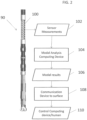
- FIG. 2 shows a BHA 90 that includes one or more sensors that are generally shown as element 100.
- the sensors may be a single sensor or multiple sensors.
- the sensors 100 may, in one embodiment, measure deflection, velocity and accelerations or any other motion as described above.
- the data produced by such sensors 100 is shown as sensor data 102.
- the data is analyzed by a computing device 104 that may be included in the BHA 90.
- the computing device 104 is shown as external to the BHA 90 but it shall be understood that it may be included in the BHA in one embodiment.
- the computing device 104 performs an operational modal analysis based on the sensor data 102. The output of this analysis is shown as modal results 106.
- a string may be modeled and its modal results determined.
- the excitation force e.g., input torque
- the excitation force is known or set.
- the excitation force is or may be unknown.
- the excitation forces are assumed to be white noise that leads to simplification in the derivation of the modal parameters (eigenfrequencies, mode shapes, modal damping) from measurement data.
- the knowledge of eigenfrequencies and modal damping may be beneficial to find optimal drilling parameters. This is especially useful to avoid resonances with the rotary speed/mud motor excitation to avoid severe lateral vibrations. Based on this knowledge, certain information may be determined or analysis performed.
- the modal analysis at device 104 determines modal results 106 that include one or more of eigenfrequencies, modal damping and modal shapes.
- This analysis includes operating with a discrete state space formulation of the structure is assumed where sensors and excitation are assumed to be disturbed by white noise. This leads to a so-called stochastic state space model. The assumption of white noise excitation leads to simplifications. It can be shown that the mathematical model can be interpreted as an impulse response of the underlying matrices. The derivation of modal parameters from an impulse response is well known in this context. In a second step it can be shown that the state matrix can then be calculated from a singular value decomposition of time-based measurement data. A modal analysis of the state matrix directly leads to eigenfrequencies, modal damping and eigenvectors (limited to the measurement positions) of the system.
- Multi-degree-of-freedom (MDOF) systems are usually described by the differential equation:
- the matrices M, Cq,K are the mass, damping and stiffness matrix of the dimension n 2 xm. Respectively n 2 is the number of degree of freedom (DOF) of the discretized dynamic system. B2 is a matrix of size n 2 xm that applies the m different forces of u(t) onto the DOFs of the system.
- the above MDOF equation can be transformed into a state space equation by defining the following terms: with the continuous state-space model: where: are defined as the so called state or system matrix and input matrix of the state-space model.
- the outputs of interest can be determined by: where are the output and direct transmission matrix.
- the output matrix C consists of the output matrices for displacement, velocity and acceleration.
- m 2 represents the number of outputs.
- the excitation is may, in embodiment, be modeled by white noise resulting in
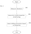
- FIG. 3 is a flow chart for a method for selecting drilling parameters for drilling a borehole penetrating the earth with a drill string.
- Block 302 calls for measuring vibration-related amplitudes of the drill string due to the applied excitation force using a vibration sensor to provide amplitude measurements.
- the vibration-related amplitudes include vibration amplitude, deflection amplitude, velocity amplitude, and bending moment amplitude.
- the sensor is disposed in a bottomhole assembly of the drill string.
- the vibration-related amplitudes are measured in a frequency domain and/or a frequency domain.
- the senor represents a plurality of sensors that may be in one location or a plurality of locations distributed along the drill string. In one or more embodiments, the sensor or sensors are disposed at locations that are not nodes of a modal shape of the drill string.
- Block 304 calls for determining with a processor one or more modal properties having one or more eigenfrequencies of the drill string using the amplitude measurements.
- the modal properties may include a modal shape and/or modal damping. According to one embodiment, determining the modal properties can be done without knowing the excitation or including it a white noise term of a model of the drill string.
- Block 306 calls for selecting drilling parameters that apply an excitation force at a frequency that avoids a selected range of frequencies that bound the one or more eigenfrequencies.
- the selection may be done by a human or automatically using a control processor.
- the range of frequencies that bound the one or more eigenfrequencies is selected so that damage to the drill string is prevented.
- operation of the drill string outside of the selected range provides for operation of drill string components within their operational specifications or design parameters. Stated in other words, the range to be avoided may be selected such that the drill string components would exceed their operational specifications or design parameters if operated within that range. Margins that encompass sensor error may be added to the selected range may be used to help insure that the drilling parameters do not cause resonant vibrations of the drill string.
- the method in FIG. 3 may also include drilling the borehole with a drilling rig using the selected drilling parameters in order to prevent or limit drill string vibrations.
- the method may also include transmitting the selected drilling parameters to a drill string controller configured to control the drill string in accordance with the selected drilling parameters.
- the method may also include controlling one or more drilling parameters using a feedback controller that receives input from a drilling parameter sensor in accordance with a signal received from a processor that selected the drilling parameters that avoid the eigenfrequencies.
- the signal includes one or more setpoints of drilling parameters that avoid the eigenfrequencies. It can be appreciated that the one or more setpoints can be transmitted to the drill string controller in real time as soon as sensor data is received and eigenfrequencies are determined.
- the method may also include constructing a mathematical model of the drill string comprising dimensions and mass distribution of the drill string; determining a location of one or more nodes of the modal shape.
- the mathematical model may include a shape and dimensions of the borehole and the drill string being disposed in the borehole so that impacts with the borehole wall may be modeled.
- various analysis components may be used, including digital and/or analog systems.
- the digital and/or analog systems may be included, for example, in the downhole electronics unit 42 or the processing unit 28.
- the systems may include components such as a processor, analog to digital converter, digital to analog converter, storage media, memory, input, output, communications link (wired, wireless, pulsed mud, optical or other), user interfaces, software programs, signal processors (digital or analog) and other such components (such as resistors, capacitors, inductors and others) to provide for operation and analyses of the apparatus and methods disclosed herein in any of several manners well-appreciated in the art.
- the teachings of the present disclosure may be used in a variety of well operations. These operations may involve using one or more treatment agents to treat a formation, the fluids resident in a formation, a wellbore, and / or equipment in the wellbore, such as production tubing.
- the treatment agents may be in the form of liquids, gases, solids, semi-solids, and mixtures thereof.
- Illustrative treatment agents include, but are not limited to, fracturing fluids, acids, steam, water, brine, anti-corrosion agents, cement, permeability modifiers, drilling muds, emulsifiers, demulsifiers, tracers, flow improvers etc.
- Illustrative well operations include, but are not limited to, hydraulic fracturing, stimulation, tracer injection, cleaning, acidizing, steam injection, water flooding, cementing, etc.
Claims (8)
- Procédé de sélection de paramètres de forage pour le forage d'un trou de forage (26) pénétrant dans la terre avec un train de tiges de forage (20), le procédé comprenant :l'élaboration d'un modèle mathématique du train de tiges de forage (20) comprenant les dimensions et la distribution de masse du train de tiges de forage (20) ;la mesure des amplitudes liées aux vibrations du train de tiges de forage (20) pendant le forage en utilisant un ou plusieurs capteurs de vibrations (100) pour fournir des mesures d'amplitude ;la détermination avec un processeur de fond de trou d'une ou plusieurs propriétés modales du train de tiges de forage (20) en utilisant les mesures d'amplitude et le modèle mathématique, les une ou plusieurs propriétés modales comprenant une ou plusieurs fréquences propres du train de tiges de forage (20), la détermination étant réalisée en incluant toute force d'excitation dans un terme de bruit blanc du modèle mathématique du train de tiges de forage (20) ; etla sélection d'une fréquence d'excitation d'un stimulus qui applique une force d'excitation au train de tiges de forage (20) à une fréquence qui évite une plage de fréquences sélectionnée qui bornent les une ou plusieurs fréquences propres en utilisant le processeur ; etle forage du trou de forage (26) avec un appareil de forage en utilisant la fréquence d'excitation sélectionnée.
- Procédé selon la revendication 1, dans lequel les une ou plusieurs propriétés modales comprennent en outre une forme modale et/ou un amortissement modal.
- Procédé selon la revendication 1, dans lequel le stimulus qui applique une force d'excitation au train de tiges de forage (20) est un dispositif d'excitation qui comprend un moteur à boue (55) et la variation de la fréquence d'excitation comprend la variation d'un débit de fluide de forage (31) à travers le train de tiges de forage (20).
- Procédé selon la revendication 3, dans lequel la variation d'un débit comprend la variation d'au moins l'une parmi une vitesse de pompage de fluide de forage (31) et une ouverture de vanne d'écoulement de fluide de forage (31).
- Procédé selon la revendication 1, dans lequel le capteur est disposé dans un ensemble de fond de trou (BHA) du train de tiges de forage (20).
- Procédé selon la revendication 1, comprenant en outre l'analyse d'une réponse du modèle mathématique pendant le forage pour fournir la forme modale des vibrations du train de tiges de forage (20).
- Procédé de sélection de paramètres de forage pour le forage d'un trou de forage (26) pénétrant dans la terre avec un train de tiges de forage (20), le procédé comprenant :l'élaboration d'un modèle mathématique du train de tiges de forage (20) comprenant les dimensions et la distribution de masse du train de tiges de forage (20) ;la mesure des amplitudes liées aux vibrations du train de tiges de forage (20) pendant le forage en utilisant un ou plusieurs capteurs de vibrations (100) pour fournir des mesures d'amplitude ;la détermination avec un processeur de fond de trou d'une ou plusieurs propriétés modales du train de tiges de forage (20) en utilisant les mesures d'amplitude et le modèle mathématique, les une ou plusieurs propriétés modales comprenant une ou plusieurs fréquences propres du train de tiges de forage (20), la détermination étant réalisée sans tenir compte d'une quelconque force d'excitation dans le modèle mathématique du train de tiges de forage (20) ; etla sélection d'une fréquence d'excitation d'un stimulus qui applique une force d'excitation au train de tiges de forage (20) à une fréquence qui évite une plage de fréquences sélectionnée qui bornent les une ou plusieurs fréquences propres en utilisant le processeur ; etle forage du trou de forage (26) avec un appareil de forage en utilisant la fréquence d'excitation sélectionnée.
- Procédé selon la revendication 7, dans lequel les une ou plusieurs propriétés modales comprennent en outre une forme modale et/ou un amortissement modal.
Applications Claiming Priority (2)
| Application Number | Priority Date | Filing Date | Title |
|---|---|---|---|
| US15/088,391 US10364663B2 (en) | 2016-04-01 | 2016-04-01 | Downhole operational modal analysis |
| PCT/US2017/024993 WO2017173070A2 (fr) | 2016-04-01 | 2017-03-30 | Analyse modale d'opération de fond de trou |
Publications (3)
| Publication Number | Publication Date |
|---|---|
| EP3436660A2 EP3436660A2 (fr) | 2019-02-06 |
| EP3436660A4 EP3436660A4 (fr) | 2019-12-11 |
| EP3436660B1 true EP3436660B1 (fr) | 2023-05-10 |
Family
ID=59960267
Family Applications (1)
| Application Number | Title | Priority Date | Filing Date |
|---|---|---|---|
| EP17776644.1A Active EP3436660B1 (fr) | 2016-04-01 | 2017-03-30 | Analyse modale d'opération de fond de trou |
Country Status (4)
| Country | Link |
|---|---|
| US (1) | US10364663B2 (fr) |
| EP (1) | EP3436660B1 (fr) |
| SA (1) | SA518400134B1 (fr) |
| WO (1) | WO2017173070A2 (fr) |
Families Citing this family (6)
| Publication number | Priority date | Publication date | Assignee | Title |
|---|---|---|---|---|
| CN112483076B (zh) * | 2019-09-11 | 2024-04-02 | 中国石油化工股份有限公司 | 一种用于识别钻井施工复杂情况的系统 |
| CN111411944B (zh) * | 2020-04-27 | 2024-04-09 | 国仪石油技术(无锡)有限公司 | 一种随钻核磁共振测井仪及其工作模式控制方法、系统 |
| US11339640B2 (en) | 2020-06-02 | 2022-05-24 | Saudi Arabian Oil Company | Method and system of drilling with geologically-driven rate of penetration |
| US11421524B2 (en) | 2020-07-13 | 2022-08-23 | Saudi Arabian Oil Company | Monitoring the condition of a drill string |
| CN113503155A (zh) * | 2021-07-21 | 2021-10-15 | 中国科学院地质与地球物理研究所 | 一种多功能随钻工程参数测量系统及测量方法 |
| WO2023168380A1 (fr) * | 2022-03-03 | 2023-09-07 | Schlumberger Technology Corporation | Procédés de prédiction et d'adaptation à une oscillation de torsion haute fréquence |
Family Cites Families (33)
| Publication number | Priority date | Publication date | Assignee | Title |
|---|---|---|---|---|
| US4291978A (en) | 1979-12-05 | 1981-09-29 | Scintrex Limited | Apparatus for automatically determining the position at which a beam of light impinges on a target |
| US4821563A (en) | 1988-01-15 | 1989-04-18 | Teleco Oilfield Services Inc. | Apparatus for measuring weight, torque and side force on a drill bit |
| US5386724A (en) | 1993-08-31 | 1995-02-07 | Schlumberger Technology Corporation | Load cells for sensing weight and torque on a drill bit while drilling a well bore |
| US5705810A (en) | 1995-12-01 | 1998-01-06 | Wang; Qi | Laser optical torquemeter |
| US6587211B1 (en) | 1999-07-28 | 2003-07-01 | Creo Srl | Interferometric torque and power sensor |
| US6948381B1 (en) | 2002-04-09 | 2005-09-27 | Rockwell Automation Technologies, Inc. | System and method for sensing torque on a rotating shaft |
| US7775099B2 (en) | 2003-11-20 | 2010-08-17 | Schlumberger Technology Corporation | Downhole tool sensor system and method |
| US20080060849A1 (en) * | 2006-09-12 | 2008-03-13 | Entchev Pavlin B | Shape memory alloy vibration isolation device |
| US7586083B2 (en) | 2007-01-03 | 2009-09-08 | Gm Global Technology Operations, Inc. | Laser sensor apparatus and method for detecting transmission shaft torque |
| US8775085B2 (en) | 2008-02-21 | 2014-07-08 | Baker Hughes Incorporated | Distributed sensors for dynamics modeling |
| JP4474494B2 (ja) | 2008-02-29 | 2010-06-02 | 株式会社フジクラ | 光周波数領域反射測定方式の物理量計測装置及びこれを用いた温度と歪みの計測方法 |
| CA2696238C (fr) | 2008-02-29 | 2013-04-16 | Fujikura Ltd. | Dispositif de mesure d'une quantite physique par mesure de la reflexion de la gamme de frequence optique et procede de mesure simultanee de la temperature et des contraintes a l'aide dudit dispositif |
| CA2724453C (fr) | 2008-06-17 | 2014-08-12 | Exxonmobil Upstream Research Company | Procedes et systemes permettant d'attenuer les vibrations de forage |
| FR2940833B1 (fr) | 2009-01-08 | 2011-03-11 | Snecma | Dispositif de mesure de torsion d'un arbre tournant |
| WO2010101548A1 (fr) | 2009-03-05 | 2010-09-10 | Halliburton Energy Services, Inc. | Analyse et commande du mouvement d'un train de tiges |
| CA2770230C (fr) | 2009-08-07 | 2016-05-17 | Exxonmobil Upstream Research Company | Procedes pour estimer une amplitude de vibration de forage de fond de trou a partir d'une mesure de surface |
| US8171805B2 (en) | 2010-02-18 | 2012-05-08 | Honeywell International Inc. | Non-contact torque determination system and method for a non-mechanically coupled rotating system |
| US8833183B2 (en) | 2010-06-21 | 2014-09-16 | The Charles Machine Works, Inc. | Method and system for monitoring bend and torque forces on a drill pipe |
| US8833487B2 (en) | 2011-04-14 | 2014-09-16 | Wwt North America Holdings, Inc. | Mechanical specific energy drilling system |
| CA2857201C (fr) | 2011-12-28 | 2016-11-15 | Halliburton Energy Services, Inc. | Systemes et procedes pour permettre un etalonnage automatique d'un capteur de poids au trepan et une regulation de la deformation d'un train de tiges de forage |
| WO2013138034A2 (fr) | 2012-03-16 | 2013-09-19 | National Oilwell DHT, L.P. | Ensemble de mesure, outil et procédé en fond de puits |
| DE102012104874B4 (de) | 2012-06-05 | 2016-05-19 | Technische Universität München | Optisches Messsystem mit Polarisationskompensation, sowie entsprechendes Verfahren |
| WO2014012173A1 (fr) | 2012-07-20 | 2014-01-23 | Advanced Test And Automation Inc. | Système et procédé permettant de mesurer un couple |
| JP6329239B2 (ja) | 2013-03-12 | 2018-05-23 | ストライカー・コーポレイション | 力及びトルクを測定するためのセンサ組立体及び方法 |
| US9657523B2 (en) | 2013-05-17 | 2017-05-23 | Baker Hughes Incorporated | Bottomhole assembly design method to reduce rotational loads |
| US9435187B2 (en) * | 2013-09-20 | 2016-09-06 | Baker Hughes Incorporated | Method to predict, illustrate, and select drilling parameters to avoid severe lateral vibrations |
| US10472944B2 (en) | 2013-09-25 | 2019-11-12 | Aps Technology, Inc. | Drilling system and associated system and method for monitoring, controlling, and predicting vibration in an underground drilling operation |
| US9567844B2 (en) * | 2013-10-10 | 2017-02-14 | Weatherford Technology Holdings, Llc | Analysis of drillstring dynamics using angular and linear motion data from multiple accelerometer pairs |
| US9976405B2 (en) | 2013-11-01 | 2018-05-22 | Baker Hughes, A Ge Company, Llc | Method to mitigate bit induced vibrations by intentionally modifying mode shapes of drill strings by mass or stiffness changes |
| US10323499B2 (en) * | 2013-12-06 | 2019-06-18 | Halliburton Energy Services, Inc. | Managing wellbore operations using uncertainty calculations |
| US20150240614A1 (en) * | 2014-02-24 | 2015-08-27 | Saudi Arabian Oil Company | Downhole bha seismic signal generator |
| BR112017004597A2 (pt) * | 2014-09-10 | 2018-01-30 | Fracture Id Inc | métodos para caracterização de propriedades de rocha e para fraturamento hidráulico. |
| US10920561B2 (en) * | 2015-01-16 | 2021-02-16 | Schlumberger Technology Corporation | Drilling assessment system |
-
2016
- 2016-04-01 US US15/088,391 patent/US10364663B2/en active Active
-
2017
- 2017-03-30 WO PCT/US2017/024993 patent/WO2017173070A2/fr active Application Filing
- 2017-03-30 EP EP17776644.1A patent/EP3436660B1/fr active Active
-
2018
- 2018-09-29 SA SA518400134A patent/SA518400134B1/ar unknown
Also Published As
| Publication number | Publication date |
|---|---|
| EP3436660A2 (fr) | 2019-02-06 |
| WO2017173070A2 (fr) | 2017-10-05 |
| US20170284185A1 (en) | 2017-10-05 |
| US10364663B2 (en) | 2019-07-30 |
| SA518400134B1 (ar) | 2023-02-07 |
| WO2017173070A3 (fr) | 2018-08-23 |
| EP3436660A4 (fr) | 2019-12-11 |
Similar Documents
| Publication | Publication Date | Title |
|---|---|---|
| EP3436660B1 (fr) | Analyse modale d'opération de fond de trou | |
| US10982526B2 (en) | Estimation of maximum load amplitudes in drilling systems independent of sensor position | |
| CA2890150C (fr) | Telemetrie magnetique passive pour sagd et puits d'intervention par filtre de kalman a fenetre de suivi linearisee | |
| US20190376386A1 (en) | Gas ratio volumetrics for reservoir navigation | |
| US11378506B2 (en) | Methods and systems for monitoring drilling fluid rheological characteristics | |
| US20190203588A1 (en) | Real-time monitoring of downhole dynamic events | |
| NO20210833A1 (en) | Systems and methods to control drilling operations based on formation orientations | |
| WO2017196714A1 (fr) | Procédés et systèmes pour optimiser une opération de forage en fonction de multiples mesures de formation | |
| US11867051B2 (en) | Incremental downhole depth methods and systems | |
| GB2599758A (en) | Predicting and reducing vibrations during downhole drilling operations | |
| US20230193740A1 (en) | Estimation of maximum load amplitudes in drilling systems using multiple independent measurements | |
| US11248463B2 (en) | Evaluation of sensors based on contextual information | |
| US9971054B2 (en) | System and method to determine communication line propagation delay | |
| EP3695097B1 (fr) | Analyse à niveau de champ de journaux d'opérations de fond de trou |
Legal Events
| Date | Code | Title | Description |
|---|---|---|---|
| STAA | Information on the status of an ep patent application or granted ep patent |
Free format text: STATUS: THE INTERNATIONAL PUBLICATION HAS BEEN MADE |
|
| PUAI | Public reference made under article 153(3) epc to a published international application that has entered the european phase |
Free format text: ORIGINAL CODE: 0009012 |
|
| STAA | Information on the status of an ep patent application or granted ep patent |
Free format text: STATUS: REQUEST FOR EXAMINATION WAS MADE |
|
| 17P | Request for examination filed |
Effective date: 20181029 |
|
| AK | Designated contracting states |
Kind code of ref document: A2 Designated state(s): AL AT BE BG CH CY CZ DE DK EE ES FI FR GB GR HR HU IE IS IT LI LT LU LV MC MK MT NL NO PL PT RO RS SE SI SK SM TR |
|
| AX | Request for extension of the european patent |
Extension state: BA ME |
|
| STAA | Information on the status of an ep patent application or granted ep patent |
Free format text: STATUS: REQUEST FOR EXAMINATION WAS MADE |
|
| RIN1 | Information on inventor provided before grant (corrected) |
Inventor name: HOHL, ANDREAS Inventor name: RECKMANN, HANNO Inventor name: ICHAOUI, MOHAMED |
|
| DAV | Request for validation of the european patent (deleted) | ||
| DAX | Request for extension of the european patent (deleted) | ||
| A4 | Supplementary search report drawn up and despatched |
Effective date: 20191113 |
|
| RIC1 | Information provided on ipc code assigned before grant |
Ipc: E21B 44/00 20060101AFI20191107BHEP Ipc: E21B 41/00 20060101ALI20191107BHEP Ipc: E21B 21/08 20060101ALI20191107BHEP |
|
| GRAP | Despatch of communication of intention to grant a patent |
Free format text: ORIGINAL CODE: EPIDOSNIGR1 |
|
| STAA | Information on the status of an ep patent application or granted ep patent |
Free format text: STATUS: GRANT OF PATENT IS INTENDED |
|
| INTG | Intention to grant announced |
Effective date: 20230223 |
|
| GRAS | Grant fee paid |
Free format text: ORIGINAL CODE: EPIDOSNIGR3 |
|
| GRAA | (expected) grant |
Free format text: ORIGINAL CODE: 0009210 |
|
| STAA | Information on the status of an ep patent application or granted ep patent |
Free format text: STATUS: THE PATENT HAS BEEN GRANTED |
|
| RAP3 | Party data changed (applicant data changed or rights of an application transferred) |
Owner name: BAKER HUGHES HOLDINGS LLC |
|
| AK | Designated contracting states |
Kind code of ref document: B1 Designated state(s): AL AT BE BG CH CY CZ DE DK EE ES FI FR GB GR HR HU IE IS IT LI LT LU LV MC MK MT NL NO PL PT RO RS SE SI SK SM TR |
|
| REG | Reference to a national code |
Ref country code: GB Ref legal event code: FG4D |
|
| REG | Reference to a national code |
Ref country code: AT Ref legal event code: REF Ref document number: 1566848 Country of ref document: AT Kind code of ref document: T Effective date: 20230515 Ref country code: CH Ref legal event code: EP |
|
| REG | Reference to a national code |
Ref country code: DE Ref legal event code: R096 Ref document number: 602017068635 Country of ref document: DE |
|
| REG | Reference to a national code |
Ref country code: IE Ref legal event code: FG4D |
|
| P01 | Opt-out of the competence of the unified patent court (upc) registered |
Effective date: 20230526 |
|
| REG | Reference to a national code |
Ref country code: NO Ref legal event code: T2 Effective date: 20230510 |
|
| REG | Reference to a national code |
Ref country code: LT Ref legal event code: MG9D |
|
| REG | Reference to a national code |
Ref country code: NL Ref legal event code: MP Effective date: 20230510 |
|
| REG | Reference to a national code |
Ref country code: AT Ref legal event code: MK05 Ref document number: 1566848 Country of ref document: AT Kind code of ref document: T Effective date: 20230510 |
|
| PG25 | Lapsed in a contracting state [announced via postgrant information from national office to epo] |
Ref country code: SE Free format text: LAPSE BECAUSE OF FAILURE TO SUBMIT A TRANSLATION OF THE DESCRIPTION OR TO PAY THE FEE WITHIN THE PRESCRIBED TIME-LIMIT Effective date: 20230510 Ref country code: PT Free format text: LAPSE BECAUSE OF FAILURE TO SUBMIT A TRANSLATION OF THE DESCRIPTION OR TO PAY THE FEE WITHIN THE PRESCRIBED TIME-LIMIT Effective date: 20230911 Ref country code: NL Free format text: LAPSE BECAUSE OF FAILURE TO SUBMIT A TRANSLATION OF THE DESCRIPTION OR TO PAY THE FEE WITHIN THE PRESCRIBED TIME-LIMIT Effective date: 20230510 Ref country code: ES Free format text: LAPSE BECAUSE OF FAILURE TO SUBMIT A TRANSLATION OF THE DESCRIPTION OR TO PAY THE FEE WITHIN THE PRESCRIBED TIME-LIMIT Effective date: 20230510 Ref country code: AT Free format text: LAPSE BECAUSE OF FAILURE TO SUBMIT A TRANSLATION OF THE DESCRIPTION OR TO PAY THE FEE WITHIN THE PRESCRIBED TIME-LIMIT Effective date: 20230510 |
|
| PG25 | Lapsed in a contracting state [announced via postgrant information from national office to epo] |
Ref country code: RS Free format text: LAPSE BECAUSE OF FAILURE TO SUBMIT A TRANSLATION OF THE DESCRIPTION OR TO PAY THE FEE WITHIN THE PRESCRIBED TIME-LIMIT Effective date: 20230510 Ref country code: PL Free format text: LAPSE BECAUSE OF FAILURE TO SUBMIT A TRANSLATION OF THE DESCRIPTION OR TO PAY THE FEE WITHIN THE PRESCRIBED TIME-LIMIT Effective date: 20230510 Ref country code: LV Free format text: LAPSE BECAUSE OF FAILURE TO SUBMIT A TRANSLATION OF THE DESCRIPTION OR TO PAY THE FEE WITHIN THE PRESCRIBED TIME-LIMIT Effective date: 20230510 Ref country code: LT Free format text: LAPSE BECAUSE OF FAILURE TO SUBMIT A TRANSLATION OF THE DESCRIPTION OR TO PAY THE FEE WITHIN THE PRESCRIBED TIME-LIMIT Effective date: 20230510 Ref country code: IS Free format text: LAPSE BECAUSE OF FAILURE TO SUBMIT A TRANSLATION OF THE DESCRIPTION OR TO PAY THE FEE WITHIN THE PRESCRIBED TIME-LIMIT Effective date: 20230910 Ref country code: HR Free format text: LAPSE BECAUSE OF FAILURE TO SUBMIT A TRANSLATION OF THE DESCRIPTION OR TO PAY THE FEE WITHIN THE PRESCRIBED TIME-LIMIT Effective date: 20230510 Ref country code: GR Free format text: LAPSE BECAUSE OF FAILURE TO SUBMIT A TRANSLATION OF THE DESCRIPTION OR TO PAY THE FEE WITHIN THE PRESCRIBED TIME-LIMIT Effective date: 20230811 |
|
| PG25 | Lapsed in a contracting state [announced via postgrant information from national office to epo] |
Ref country code: FI Free format text: LAPSE BECAUSE OF FAILURE TO SUBMIT A TRANSLATION OF THE DESCRIPTION OR TO PAY THE FEE WITHIN THE PRESCRIBED TIME-LIMIT Effective date: 20230510 |
|
| PG25 | Lapsed in a contracting state [announced via postgrant information from national office to epo] |
Ref country code: SK Free format text: LAPSE BECAUSE OF FAILURE TO SUBMIT A TRANSLATION OF THE DESCRIPTION OR TO PAY THE FEE WITHIN THE PRESCRIBED TIME-LIMIT Effective date: 20230510 |
|
| PG25 | Lapsed in a contracting state [announced via postgrant information from national office to epo] |
Ref country code: SM Free format text: LAPSE BECAUSE OF FAILURE TO SUBMIT A TRANSLATION OF THE DESCRIPTION OR TO PAY THE FEE WITHIN THE PRESCRIBED TIME-LIMIT Effective date: 20230510 Ref country code: SK Free format text: LAPSE BECAUSE OF FAILURE TO SUBMIT A TRANSLATION OF THE DESCRIPTION OR TO PAY THE FEE WITHIN THE PRESCRIBED TIME-LIMIT Effective date: 20230510 Ref country code: RO Free format text: LAPSE BECAUSE OF FAILURE TO SUBMIT A TRANSLATION OF THE DESCRIPTION OR TO PAY THE FEE WITHIN THE PRESCRIBED TIME-LIMIT Effective date: 20230510 Ref country code: EE Free format text: LAPSE BECAUSE OF FAILURE TO SUBMIT A TRANSLATION OF THE DESCRIPTION OR TO PAY THE FEE WITHIN THE PRESCRIBED TIME-LIMIT Effective date: 20230510 Ref country code: DK Free format text: LAPSE BECAUSE OF FAILURE TO SUBMIT A TRANSLATION OF THE DESCRIPTION OR TO PAY THE FEE WITHIN THE PRESCRIBED TIME-LIMIT Effective date: 20230510 Ref country code: CZ Free format text: LAPSE BECAUSE OF FAILURE TO SUBMIT A TRANSLATION OF THE DESCRIPTION OR TO PAY THE FEE WITHIN THE PRESCRIBED TIME-LIMIT Effective date: 20230510 |
|
| REG | Reference to a national code |
Ref country code: DE Ref legal event code: R097 Ref document number: 602017068635 Country of ref document: DE |
|
| PLBE | No opposition filed within time limit |
Free format text: ORIGINAL CODE: 0009261 |
|
| STAA | Information on the status of an ep patent application or granted ep patent |
Free format text: STATUS: NO OPPOSITION FILED WITHIN TIME LIMIT |
|
| 26N | No opposition filed |
Effective date: 20240213 |