EP3436301B1 - Single electric motor drive axle with multiple ratios - Google Patents
Single electric motor drive axle with multiple ratios Download PDFInfo
- Publication number
- EP3436301B1 EP3436301B1 EP17716034.8A EP17716034A EP3436301B1 EP 3436301 B1 EP3436301 B1 EP 3436301B1 EP 17716034 A EP17716034 A EP 17716034A EP 3436301 B1 EP3436301 B1 EP 3436301B1
- Authority
- EP
- European Patent Office
- Prior art keywords
- electric drive
- drive axle
- axle
- planetary gear
- stationary member
- Prior art date
- Legal status (The legal status is an assumption and is not a legal conclusion. Google has not performed a legal analysis and makes no representation as to the accuracy of the status listed.)
- Active
Links
- 230000000712 assembly Effects 0.000 description 5
- 238000000429 assembly Methods 0.000 description 5
- 238000004891 communication Methods 0.000 description 4
- 239000000446 fuel Substances 0.000 description 3
- 238000010586 diagram Methods 0.000 description 2
- 238000004146 energy storage Methods 0.000 description 2
- 230000001172 regenerating effect Effects 0.000 description 2
- OKTJSMMVPCPJKN-UHFFFAOYSA-N Carbon Chemical compound [C] OKTJSMMVPCPJKN-UHFFFAOYSA-N 0.000 description 1
- 230000001133 acceleration Effects 0.000 description 1
- 238000003915 air pollution Methods 0.000 description 1
- 229910052799 carbon Inorganic materials 0.000 description 1
- 230000000694 effects Effects 0.000 description 1
- 238000005516 engineering process Methods 0.000 description 1
- 238000000034 method Methods 0.000 description 1
- 238000004806 packaging method and process Methods 0.000 description 1
- 239000000725 suspension Substances 0.000 description 1
- 230000001360 synchronised effect Effects 0.000 description 1
Images


Classifications
-
- F—MECHANICAL ENGINEERING; LIGHTING; HEATING; WEAPONS; BLASTING
- F16—ENGINEERING ELEMENTS AND UNITS; GENERAL MEASURES FOR PRODUCING AND MAINTAINING EFFECTIVE FUNCTIONING OF MACHINES OR INSTALLATIONS; THERMAL INSULATION IN GENERAL
- F16H—GEARING
- F16H37/00—Combinations of mechanical gearings, not provided for in groups F16H1/00 - F16H35/00
- F16H37/02—Combinations of mechanical gearings, not provided for in groups F16H1/00 - F16H35/00 comprising essentially only toothed or friction gearings
- F16H37/06—Combinations of mechanical gearings, not provided for in groups F16H1/00 - F16H35/00 comprising essentially only toothed or friction gearings with a plurality of driving or driven shafts; with arrangements for dividing torque between two or more intermediate shafts
- F16H37/08—Combinations of mechanical gearings, not provided for in groups F16H1/00 - F16H35/00 comprising essentially only toothed or friction gearings with a plurality of driving or driven shafts; with arrangements for dividing torque between two or more intermediate shafts with differential gearing
- F16H37/0806—Combinations of mechanical gearings, not provided for in groups F16H1/00 - F16H35/00 comprising essentially only toothed or friction gearings with a plurality of driving or driven shafts; with arrangements for dividing torque between two or more intermediate shafts with differential gearing with a plurality of driving or driven shafts
- F16H37/0813—Combinations of mechanical gearings, not provided for in groups F16H1/00 - F16H35/00 comprising essentially only toothed or friction gearings with a plurality of driving or driven shafts; with arrangements for dividing torque between two or more intermediate shafts with differential gearing with a plurality of driving or driven shafts with only one input shaft
- F16H37/082—Combinations of mechanical gearings, not provided for in groups F16H1/00 - F16H35/00 comprising essentially only toothed or friction gearings with a plurality of driving or driven shafts; with arrangements for dividing torque between two or more intermediate shafts with differential gearing with a plurality of driving or driven shafts with only one input shaft and additional planetary reduction gears
-
- B—PERFORMING OPERATIONS; TRANSPORTING
- B60—VEHICLES IN GENERAL
- B60B—VEHICLE WHEELS; CASTORS; AXLES FOR WHEELS OR CASTORS; INCREASING WHEEL ADHESION
- B60B35/00—Axle units; Parts thereof ; Arrangements for lubrication of axles
- B60B35/12—Torque-transmitting axles
- B60B35/121—Power-transmission from drive shaft to hub
- B60B35/122—Power-transmission from drive shaft to hub using gearings
- B60B35/125—Power-transmission from drive shaft to hub using gearings of the planetary type
-
- B—PERFORMING OPERATIONS; TRANSPORTING
- B60—VEHICLES IN GENERAL
- B60K—ARRANGEMENT OR MOUNTING OF PROPULSION UNITS OR OF TRANSMISSIONS IN VEHICLES; ARRANGEMENT OR MOUNTING OF PLURAL DIVERSE PRIME-MOVERS IN VEHICLES; AUXILIARY DRIVES FOR VEHICLES; INSTRUMENTATION OR DASHBOARDS FOR VEHICLES; ARRANGEMENTS IN CONNECTION WITH COOLING, AIR INTAKE, GAS EXHAUST OR FUEL SUPPLY OF PROPULSION UNITS IN VEHICLES
- B60K1/00—Arrangement or mounting of electrical propulsion units
-
- B—PERFORMING OPERATIONS; TRANSPORTING
- B60—VEHICLES IN GENERAL
- B60K—ARRANGEMENT OR MOUNTING OF PROPULSION UNITS OR OF TRANSMISSIONS IN VEHICLES; ARRANGEMENT OR MOUNTING OF PLURAL DIVERSE PRIME-MOVERS IN VEHICLES; AUXILIARY DRIVES FOR VEHICLES; INSTRUMENTATION OR DASHBOARDS FOR VEHICLES; ARRANGEMENTS IN CONNECTION WITH COOLING, AIR INTAKE, GAS EXHAUST OR FUEL SUPPLY OF PROPULSION UNITS IN VEHICLES
- B60K17/00—Arrangement or mounting of transmissions in vehicles
- B60K17/02—Arrangement or mounting of transmissions in vehicles characterised by arrangement, location, or kind of clutch
-
- B—PERFORMING OPERATIONS; TRANSPORTING
- B60—VEHICLES IN GENERAL
- B60K—ARRANGEMENT OR MOUNTING OF PROPULSION UNITS OR OF TRANSMISSIONS IN VEHICLES; ARRANGEMENT OR MOUNTING OF PLURAL DIVERSE PRIME-MOVERS IN VEHICLES; AUXILIARY DRIVES FOR VEHICLES; INSTRUMENTATION OR DASHBOARDS FOR VEHICLES; ARRANGEMENTS IN CONNECTION WITH COOLING, AIR INTAKE, GAS EXHAUST OR FUEL SUPPLY OF PROPULSION UNITS IN VEHICLES
- B60K17/00—Arrangement or mounting of transmissions in vehicles
- B60K17/04—Arrangement or mounting of transmissions in vehicles characterised by arrangement, location, or kind of gearing
- B60K17/043—Transmission unit disposed in on near the vehicle wheel, or between the differential gear unit and the wheel
- B60K17/046—Transmission unit disposed in on near the vehicle wheel, or between the differential gear unit and the wheel with planetary gearing having orbital motion
-
- B—PERFORMING OPERATIONS; TRANSPORTING
- B60—VEHICLES IN GENERAL
- B60K—ARRANGEMENT OR MOUNTING OF PROPULSION UNITS OR OF TRANSMISSIONS IN VEHICLES; ARRANGEMENT OR MOUNTING OF PLURAL DIVERSE PRIME-MOVERS IN VEHICLES; AUXILIARY DRIVES FOR VEHICLES; INSTRUMENTATION OR DASHBOARDS FOR VEHICLES; ARRANGEMENTS IN CONNECTION WITH COOLING, AIR INTAKE, GAS EXHAUST OR FUEL SUPPLY OF PROPULSION UNITS IN VEHICLES
- B60K17/00—Arrangement or mounting of transmissions in vehicles
- B60K17/04—Arrangement or mounting of transmissions in vehicles characterised by arrangement, location, or kind of gearing
- B60K17/16—Arrangement or mounting of transmissions in vehicles characterised by arrangement, location, or kind of gearing of differential gearing
- B60K17/165—Arrangement or mounting of transmissions in vehicles characterised by arrangement, location, or kind of gearing of differential gearing provided between independent half axles
-
- B—PERFORMING OPERATIONS; TRANSPORTING
- B60—VEHICLES IN GENERAL
- B60K—ARRANGEMENT OR MOUNTING OF PROPULSION UNITS OR OF TRANSMISSIONS IN VEHICLES; ARRANGEMENT OR MOUNTING OF PLURAL DIVERSE PRIME-MOVERS IN VEHICLES; AUXILIARY DRIVES FOR VEHICLES; INSTRUMENTATION OR DASHBOARDS FOR VEHICLES; ARRANGEMENTS IN CONNECTION WITH COOLING, AIR INTAKE, GAS EXHAUST OR FUEL SUPPLY OF PROPULSION UNITS IN VEHICLES
- B60K6/00—Arrangement or mounting of plural diverse prime-movers for mutual or common propulsion, e.g. hybrid propulsion systems comprising electric motors and internal combustion engines ; Control systems therefor, i.e. systems controlling two or more prime movers, or controlling one of these prime movers and any of the transmission, drive or drive units Informative references: mechanical gearings with secondary electric drive F16H3/72; arrangements for handling mechanical energy structurally associated with the dynamo-electric machine H02K7/00; machines comprising structurally interrelated motor and generator parts H02K51/00; dynamo-electric machines not otherwise provided for in H02K see H02K99/00
- B60K6/20—Arrangement or mounting of plural diverse prime-movers for mutual or common propulsion, e.g. hybrid propulsion systems comprising electric motors and internal combustion engines ; Control systems therefor, i.e. systems controlling two or more prime movers, or controlling one of these prime movers and any of the transmission, drive or drive units Informative references: mechanical gearings with secondary electric drive F16H3/72; arrangements for handling mechanical energy structurally associated with the dynamo-electric machine H02K7/00; machines comprising structurally interrelated motor and generator parts H02K51/00; dynamo-electric machines not otherwise provided for in H02K see H02K99/00 the prime-movers consisting of electric motors and internal combustion engines, e.g. HEVs
- B60K6/22—Arrangement or mounting of plural diverse prime-movers for mutual or common propulsion, e.g. hybrid propulsion systems comprising electric motors and internal combustion engines ; Control systems therefor, i.e. systems controlling two or more prime movers, or controlling one of these prime movers and any of the transmission, drive or drive units Informative references: mechanical gearings with secondary electric drive F16H3/72; arrangements for handling mechanical energy structurally associated with the dynamo-electric machine H02K7/00; machines comprising structurally interrelated motor and generator parts H02K51/00; dynamo-electric machines not otherwise provided for in H02K see H02K99/00 the prime-movers consisting of electric motors and internal combustion engines, e.g. HEVs characterised by apparatus, components or means specially adapted for HEVs
- B60K6/26—Arrangement or mounting of plural diverse prime-movers for mutual or common propulsion, e.g. hybrid propulsion systems comprising electric motors and internal combustion engines ; Control systems therefor, i.e. systems controlling two or more prime movers, or controlling one of these prime movers and any of the transmission, drive or drive units Informative references: mechanical gearings with secondary electric drive F16H3/72; arrangements for handling mechanical energy structurally associated with the dynamo-electric machine H02K7/00; machines comprising structurally interrelated motor and generator parts H02K51/00; dynamo-electric machines not otherwise provided for in H02K see H02K99/00 the prime-movers consisting of electric motors and internal combustion engines, e.g. HEVs characterised by apparatus, components or means specially adapted for HEVs characterised by the motors or the generators
-
- B—PERFORMING OPERATIONS; TRANSPORTING
- B60—VEHICLES IN GENERAL
- B60K—ARRANGEMENT OR MOUNTING OF PROPULSION UNITS OR OF TRANSMISSIONS IN VEHICLES; ARRANGEMENT OR MOUNTING OF PLURAL DIVERSE PRIME-MOVERS IN VEHICLES; AUXILIARY DRIVES FOR VEHICLES; INSTRUMENTATION OR DASHBOARDS FOR VEHICLES; ARRANGEMENTS IN CONNECTION WITH COOLING, AIR INTAKE, GAS EXHAUST OR FUEL SUPPLY OF PROPULSION UNITS IN VEHICLES
- B60K6/00—Arrangement or mounting of plural diverse prime-movers for mutual or common propulsion, e.g. hybrid propulsion systems comprising electric motors and internal combustion engines ; Control systems therefor, i.e. systems controlling two or more prime movers, or controlling one of these prime movers and any of the transmission, drive or drive units Informative references: mechanical gearings with secondary electric drive F16H3/72; arrangements for handling mechanical energy structurally associated with the dynamo-electric machine H02K7/00; machines comprising structurally interrelated motor and generator parts H02K51/00; dynamo-electric machines not otherwise provided for in H02K see H02K99/00
- B60K6/20—Arrangement or mounting of plural diverse prime-movers for mutual or common propulsion, e.g. hybrid propulsion systems comprising electric motors and internal combustion engines ; Control systems therefor, i.e. systems controlling two or more prime movers, or controlling one of these prime movers and any of the transmission, drive or drive units Informative references: mechanical gearings with secondary electric drive F16H3/72; arrangements for handling mechanical energy structurally associated with the dynamo-electric machine H02K7/00; machines comprising structurally interrelated motor and generator parts H02K51/00; dynamo-electric machines not otherwise provided for in H02K see H02K99/00 the prime-movers consisting of electric motors and internal combustion engines, e.g. HEVs
- B60K6/22—Arrangement or mounting of plural diverse prime-movers for mutual or common propulsion, e.g. hybrid propulsion systems comprising electric motors and internal combustion engines ; Control systems therefor, i.e. systems controlling two or more prime movers, or controlling one of these prime movers and any of the transmission, drive or drive units Informative references: mechanical gearings with secondary electric drive F16H3/72; arrangements for handling mechanical energy structurally associated with the dynamo-electric machine H02K7/00; machines comprising structurally interrelated motor and generator parts H02K51/00; dynamo-electric machines not otherwise provided for in H02K see H02K99/00 the prime-movers consisting of electric motors and internal combustion engines, e.g. HEVs characterised by apparatus, components or means specially adapted for HEVs
- B60K6/36—Arrangement or mounting of plural diverse prime-movers for mutual or common propulsion, e.g. hybrid propulsion systems comprising electric motors and internal combustion engines ; Control systems therefor, i.e. systems controlling two or more prime movers, or controlling one of these prime movers and any of the transmission, drive or drive units Informative references: mechanical gearings with secondary electric drive F16H3/72; arrangements for handling mechanical energy structurally associated with the dynamo-electric machine H02K7/00; machines comprising structurally interrelated motor and generator parts H02K51/00; dynamo-electric machines not otherwise provided for in H02K see H02K99/00 the prime-movers consisting of electric motors and internal combustion engines, e.g. HEVs characterised by apparatus, components or means specially adapted for HEVs characterised by the transmission gearings
- B60K6/365—Arrangement or mounting of plural diverse prime-movers for mutual or common propulsion, e.g. hybrid propulsion systems comprising electric motors and internal combustion engines ; Control systems therefor, i.e. systems controlling two or more prime movers, or controlling one of these prime movers and any of the transmission, drive or drive units Informative references: mechanical gearings with secondary electric drive F16H3/72; arrangements for handling mechanical energy structurally associated with the dynamo-electric machine H02K7/00; machines comprising structurally interrelated motor and generator parts H02K51/00; dynamo-electric machines not otherwise provided for in H02K see H02K99/00 the prime-movers consisting of electric motors and internal combustion engines, e.g. HEVs characterised by apparatus, components or means specially adapted for HEVs characterised by the transmission gearings with the gears having orbital motion
-
- F—MECHANICAL ENGINEERING; LIGHTING; HEATING; WEAPONS; BLASTING
- F16—ENGINEERING ELEMENTS AND UNITS; GENERAL MEASURES FOR PRODUCING AND MAINTAINING EFFECTIVE FUNCTIONING OF MACHINES OR INSTALLATIONS; THERMAL INSULATION IN GENERAL
- F16H—GEARING
- F16H3/00—Toothed gearings for conveying rotary motion with variable gear ratio or for reversing rotary motion
- F16H3/44—Toothed gearings for conveying rotary motion with variable gear ratio or for reversing rotary motion using gears having orbital motion
- F16H3/46—Gearings having only two central gears, connected by orbital gears
- F16H3/48—Gearings having only two central gears, connected by orbital gears with single orbital gears or pairs of rigidly-connected orbital gears
- F16H3/52—Gearings having only two central gears, connected by orbital gears with single orbital gears or pairs of rigidly-connected orbital gears comprising orbital spur gears
- F16H3/54—Gearings having only two central gears, connected by orbital gears with single orbital gears or pairs of rigidly-connected orbital gears comprising orbital spur gears one of the central gears being internally toothed and the other externally toothed
-
- H—ELECTRICITY
- H02—GENERATION; CONVERSION OR DISTRIBUTION OF ELECTRIC POWER
- H02K—DYNAMO-ELECTRIC MACHINES
- H02K7/00—Arrangements for handling mechanical energy structurally associated with dynamo-electric machines, e.g. structural association with mechanical driving motors or auxiliary dynamo-electric machines
- H02K7/006—Structural association of a motor or generator with the drive train of a motor vehicle
-
- H—ELECTRICITY
- H02—GENERATION; CONVERSION OR DISTRIBUTION OF ELECTRIC POWER
- H02K—DYNAMO-ELECTRIC MACHINES
- H02K7/00—Arrangements for handling mechanical energy structurally associated with dynamo-electric machines, e.g. structural association with mechanical driving motors or auxiliary dynamo-electric machines
- H02K7/10—Structural association with clutches, brakes, gears, pulleys or mechanical starters
- H02K7/108—Structural association with clutches, brakes, gears, pulleys or mechanical starters with friction clutches
-
- H—ELECTRICITY
- H02—GENERATION; CONVERSION OR DISTRIBUTION OF ELECTRIC POWER
- H02K—DYNAMO-ELECTRIC MACHINES
- H02K7/00—Arrangements for handling mechanical energy structurally associated with dynamo-electric machines, e.g. structural association with mechanical driving motors or auxiliary dynamo-electric machines
- H02K7/10—Structural association with clutches, brakes, gears, pulleys or mechanical starters
- H02K7/116—Structural association with clutches, brakes, gears, pulleys or mechanical starters with gears
-
- B—PERFORMING OPERATIONS; TRANSPORTING
- B60—VEHICLES IN GENERAL
- B60K—ARRANGEMENT OR MOUNTING OF PROPULSION UNITS OR OF TRANSMISSIONS IN VEHICLES; ARRANGEMENT OR MOUNTING OF PLURAL DIVERSE PRIME-MOVERS IN VEHICLES; AUXILIARY DRIVES FOR VEHICLES; INSTRUMENTATION OR DASHBOARDS FOR VEHICLES; ARRANGEMENTS IN CONNECTION WITH COOLING, AIR INTAKE, GAS EXHAUST OR FUEL SUPPLY OF PROPULSION UNITS IN VEHICLES
- B60K1/00—Arrangement or mounting of electrical propulsion units
- B60K2001/001—Arrangement or mounting of electrical propulsion units one motor mounted on a propulsion axle for rotating right and left wheels of this axle
-
- B—PERFORMING OPERATIONS; TRANSPORTING
- B60—VEHICLES IN GENERAL
- B60Y—INDEXING SCHEME RELATING TO ASPECTS CROSS-CUTTING VEHICLE TECHNOLOGY
- B60Y2200/00—Type of vehicle
- B60Y2200/90—Vehicles comprising electric prime movers
- B60Y2200/91—Electric vehicles
-
- B—PERFORMING OPERATIONS; TRANSPORTING
- B60—VEHICLES IN GENERAL
- B60Y—INDEXING SCHEME RELATING TO ASPECTS CROSS-CUTTING VEHICLE TECHNOLOGY
- B60Y2200/00—Type of vehicle
- B60Y2200/90—Vehicles comprising electric prime movers
- B60Y2200/92—Hybrid vehicles
-
- B—PERFORMING OPERATIONS; TRANSPORTING
- B60—VEHICLES IN GENERAL
- B60Y—INDEXING SCHEME RELATING TO ASPECTS CROSS-CUTTING VEHICLE TECHNOLOGY
- B60Y2400/00—Special features of vehicle units
- B60Y2400/70—Gearings
- B60Y2400/73—Planetary gearings
-
- F—MECHANICAL ENGINEERING; LIGHTING; HEATING; WEAPONS; BLASTING
- F16—ENGINEERING ELEMENTS AND UNITS; GENERAL MEASURES FOR PRODUCING AND MAINTAINING EFFECTIVE FUNCTIONING OF MACHINES OR INSTALLATIONS; THERMAL INSULATION IN GENERAL
- F16D—COUPLINGS FOR TRANSMITTING ROTATION; CLUTCHES; BRAKES
- F16D11/00—Clutches in which the members have interengaging parts
-
- F—MECHANICAL ENGINEERING; LIGHTING; HEATING; WEAPONS; BLASTING
- F16—ENGINEERING ELEMENTS AND UNITS; GENERAL MEASURES FOR PRODUCING AND MAINTAINING EFFECTIVE FUNCTIONING OF MACHINES OR INSTALLATIONS; THERMAL INSULATION IN GENERAL
- F16H—GEARING
- F16H2200/00—Transmissions for multiple ratios
- F16H2200/0021—Transmissions for multiple ratios specially adapted for electric vehicles
-
- F—MECHANICAL ENGINEERING; LIGHTING; HEATING; WEAPONS; BLASTING
- F16—ENGINEERING ELEMENTS AND UNITS; GENERAL MEASURES FOR PRODUCING AND MAINTAINING EFFECTIVE FUNCTIONING OF MACHINES OR INSTALLATIONS; THERMAL INSULATION IN GENERAL
- F16H—GEARING
- F16H2200/00—Transmissions for multiple ratios
- F16H2200/003—Transmissions for multiple ratios characterised by the number of forward speeds
- F16H2200/0034—Transmissions for multiple ratios characterised by the number of forward speeds the gear ratios comprising two forward speeds
-
- F—MECHANICAL ENGINEERING; LIGHTING; HEATING; WEAPONS; BLASTING
- F16—ENGINEERING ELEMENTS AND UNITS; GENERAL MEASURES FOR PRODUCING AND MAINTAINING EFFECTIVE FUNCTIONING OF MACHINES OR INSTALLATIONS; THERMAL INSULATION IN GENERAL
- F16H—GEARING
- F16H2200/00—Transmissions for multiple ratios
- F16H2200/003—Transmissions for multiple ratios characterised by the number of forward speeds
- F16H2200/0039—Transmissions for multiple ratios characterised by the number of forward speeds the gear ratios comprising three forward speeds
-
- F—MECHANICAL ENGINEERING; LIGHTING; HEATING; WEAPONS; BLASTING
- F16—ENGINEERING ELEMENTS AND UNITS; GENERAL MEASURES FOR PRODUCING AND MAINTAINING EFFECTIVE FUNCTIONING OF MACHINES OR INSTALLATIONS; THERMAL INSULATION IN GENERAL
- F16H—GEARING
- F16H2200/00—Transmissions for multiple ratios
- F16H2200/20—Transmissions using gears with orbital motion
- F16H2200/2002—Transmissions using gears with orbital motion characterised by the number of sets of orbital gears
- F16H2200/2005—Transmissions using gears with orbital motion characterised by the number of sets of orbital gears with one sets of orbital gears
-
- F—MECHANICAL ENGINEERING; LIGHTING; HEATING; WEAPONS; BLASTING
- F16—ENGINEERING ELEMENTS AND UNITS; GENERAL MEASURES FOR PRODUCING AND MAINTAINING EFFECTIVE FUNCTIONING OF MACHINES OR INSTALLATIONS; THERMAL INSULATION IN GENERAL
- F16H—GEARING
- F16H2200/00—Transmissions for multiple ratios
- F16H2200/20—Transmissions using gears with orbital motion
- F16H2200/203—Transmissions using gears with orbital motion characterised by the engaging friction means not of the freewheel type, e.g. friction clutches or brakes
- F16H2200/2041—Transmissions using gears with orbital motion characterised by the engaging friction means not of the freewheel type, e.g. friction clutches or brakes with four engaging means
-
- F—MECHANICAL ENGINEERING; LIGHTING; HEATING; WEAPONS; BLASTING
- F16—ENGINEERING ELEMENTS AND UNITS; GENERAL MEASURES FOR PRODUCING AND MAINTAINING EFFECTIVE FUNCTIONING OF MACHINES OR INSTALLATIONS; THERMAL INSULATION IN GENERAL
- F16H—GEARING
- F16H2200/00—Transmissions for multiple ratios
- F16H2200/20—Transmissions using gears with orbital motion
- F16H2200/203—Transmissions using gears with orbital motion characterised by the engaging friction means not of the freewheel type, e.g. friction clutches or brakes
- F16H2200/2064—Transmissions using gears with orbital motion characterised by the engaging friction means not of the freewheel type, e.g. friction clutches or brakes using at least one positive clutch, e.g. dog clutch
-
- F—MECHANICAL ENGINEERING; LIGHTING; HEATING; WEAPONS; BLASTING
- F16—ENGINEERING ELEMENTS AND UNITS; GENERAL MEASURES FOR PRODUCING AND MAINTAINING EFFECTIVE FUNCTIONING OF MACHINES OR INSTALLATIONS; THERMAL INSULATION IN GENERAL
- F16H—GEARING
- F16H2200/00—Transmissions for multiple ratios
- F16H2200/20—Transmissions using gears with orbital motion
- F16H2200/2094—Transmissions using gears with orbital motion using positive clutches, e.g. dog clutches
Definitions
- an electric drive axle for a motor vehicle and, more particularly, an electric drive axle having a single electric motor that provides two and three speed configurations.
- WO 2012/007030 A1 shows more specifically an electric drive axle for a motor vehicle comprising an axle housing, an electric motor having an output shaft, a fixed ratio planetary gear arrangement including a sun gear, a ring gear, and a carrier connecting the sun gear and ring gear, a differential unit including a differential gear arrangement housed within a differential case and a first clutch selectively operable to connect the ring gear to a stationary member of the electric drive axle, wherein the sun gear is drivingly connected to the output shaft of the motor and wherein the carrier is in driving engagement with the differential case.
- FR 2 864 191 A1 An exemplary differential for a motor vehicle is shown in FR 2 864 191 A1 .
- Current technology for electrified motors used in motor vehicles have a limited spread in torque and speed.
- the use of electric motors drivetrains can be optimized to efficiently deliver high torque at low speeds and low torque at high speeds, but not both.
- an electric drive axle for a motor vehicle comprising an axle housing, an electric motor having an output shaft directly driven by a bevel pinion gear coupled thereto, a fixed ratio planetary gear set including a sun gear, a ring gear, and a carrier connecting the sun gear and ring gear, a differential unit including a differential gear arrangement housed within a differential case, wherein the carrier is in driving engagement with the differential case, a first clutch configured to selectively couple the sun gear to the bevel pinion gear or to a first stationary member of the electric drive axle (210), and a second clutch configured to selectively couple the ring gear to a second stationary member, wherein the electric drive axle is configured to be operated in a first mode of operation by engaging the first clutch to selectively couple the sun gear to the first stationary member, wherein the electric drive axle is configured to be operated in a second mode of operation by not engaging the first clutch, and wherein the electric drive axle is configured to be operated in a third mode of operation by engaging the second clutch to selectively couple the ring
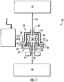
- FIG. 1 is a schematic view of an electric drive axle 10 for a motor vehicle according to an embodiment which is not part of the invention.
- the electric drive axle 10 includes a motor-generator 12, a reducing planetary gear set 14, a differential unit 16 and two axle half shafts 18, 20. As is depicted the electric drive axle 10 includes the five assembles 12, 14, 16, 18, 20, but is understood that the axle 10 may include fewer or more assemblies.
- the motor-generator 12 is coupled to an axle housing (not shown).
- the motor-generator 12 is in electrical communication with a controller (not shown) and an energy storage device (not shown).
- the energy storage device can be a battery.
- the motor-generator 12 may apply force to or retard a portion of the electric drive axle 10 it is drivingly engaged with.
- the motor-generator 12 is positioned within an axle housing. It is to be understood that the battery can be replaced with a fuel cell for a fuel cell electric vehicle drivetrain (FCEV).
- FCEV fuel cell electric vehicle drivetrain
- the motor-generator 12 is arranged transversely to axle half shafts 18, 20 of the motor vehicle and directly drives an output shaft 22.
- the output shaft 22 is drivingly connected to a bevel pinion 24.
- the bevel pinion 24 may be integrally formed with the output shaft 22.
- the bevel pinion 24 meshes with a bevel gear 26 drivingly engaged with the reducing planetary gear set 14.
- the bevel gear 26 may be one of a hypoid gear, a spiral bevel gear, a straight bevel gear, or any other gear known to those skilled in the art.
- the bevel pinion 24 and bevel gear 26 can provide a gear ratio of 6.5:1, but is not limited thereto.
- the bevel gear 26 is drivingly engaged with the planetary gear set 14.
- the planetary gear set 14 is integrated into the electric drive axle 10 and positioned between the bevel gear 26 and the axle half shafts 18, 20.
- the planetary gear set 14 is a fixed ratio planetary gear set.
- the planetary gear set 14 is drivingly engaged with the bevel gear 26 and the differential unit 16.
- the planetary gear set 14 includes a sun gear portion 28, a ring gear portion 30 and a carrier portion 32 connecting the sun gear portion 28 and the ring gear portion 30.
- the planetary gear set 14 can include additional reducing gear sets to achieve a desired gear reduction depending on the application the electric drive axle 10 is used.
- the ring gear portion 30 is in driving engagement with the motor-generator 12 via the bevel gear 26.
- the carrier portion 32 is in driving engagement with a differential case 34 including a differential gear arrangement 36 of the differential unit 16.
- the differential gear arrangement 36 includes a pair of pinion gears 38 and side gears 40, 42 rotatably supported in the differential case 34.
- the differential case 34 rotates around a rotational axis Z along with the two axle half shafts 18, 20 which are supported coaxially to the rotational axis Z.
- the side gears 40, 42 mesh with the pinion gears 38 and engage axle half shafts 18, 20 respectively.
- the output axle half shafts 18, 20 lead to wheel assemblies 44, 46.
- the pinion gears 38 are rotatably supported on a pinion shaft 48 secured to the differential case 34.
- the wheel assemblies 44, 46 include left and right wheels 44a, 46a respectively that are powered by the electric drive axle 10.
- the sun gear portion 28 is permanently grounded to a stationary member 49 of the motor vehicle resulting in the planetary gear set 14 producing a reducing planetary fixed planetary gear ratio.
- the stationary member 49 is an axle housing, but is not limited thereto.
- the stationary member 49 is positioned between the planetary gear set 14 and the wheel assembly 46.
- the planetary gear set may have a gear ratio of 1.4:1.
- the planetary gear set 14 may have other configurations that facilitate a similar operation and the position of the stationary member 49 can vary depending on the arrangement of the planetary gear set 14.
- the fixed planetary gear ration provided by the planetary gear set 14 allows for the size of the electric motor 12 to be reduced.
- the electric drive axle 10 can include a clutch 50 which selectively grounds the sun gear portion 28 to the stationary member 49 providing a two-speed electric drive axle.
- the electric drive axle 10 provides a first planetary gear ratio and when the sun gear portion 28 is not grounded, the electric drive axle 10 provides a second planetary gear ratio or a direct drive ratio.
- the first planetary gear ratio is 1.4:1, but is not limited thereto. It is understood that the planetary gear set 14 may have other configurations that facilitate a similar operation and the position of the stationary member 49 can vary depending on the arrangement of the planetary gear set 14.
- the clutch 50 is a dog clutch; however, other torque transmitting devices can be used.
- the clutch 50 is in communication with an actuator.
- the actuator can be, but is not limited to, an electromagnetic actuator a pneumatic actuator.
- the actuator can be controller by the controller and/or a supervisory vehicle control system (SVC).
- the motor-generator 12, bevel gears 24, 26, planetary gear set 14 and differential unit 36 are integrated into a single unit on the axle of the motor vehicle providing a minimal packaging envelope that is easily adaptable to existing motor vehicle chassis and suspension systems.
- FIG. 3 and 4 illustrate electric dive axles according embodiments which are not part of the invention.
- the electric drive axles are variations of the electric drive axle 10 and have similar features thereto.
- the embodiments shown in FIG. 3 to 5 include similar components to the electric drive axle 10. Similar features of the embodiment shown in FIG. 3 to 5 are numbered similarly in series. Different and additional features of the variation shown in FIG. 3 to 5 are described hereinbelow and can be appreciated by one skilled in the art in view of FIG. 1 and the other embodiments illustrated and described in this disclosure.
- the sun gear portion 128 of planetary gear set 114 of the electric drive axle 110 is drivingly engaged with the motor-generator 112 via the bevel pinion 124 and the bevel gear 126.
- the bevel pinion 124 and bevel gear 126 can have a 5:1 bevel gear ratio, but is not limited thereto.
- the carrier portion 132 of planetary gear set 114 is in driving engagement with a portion of the differential housing 134 including the differential gear arrangement 136.
- the ring gear portion 130 is permanently grounded to a stationary member 149 to produce a fixed planetary gear ratio.
- the stationary member 149 is positioned between the differential unit 116 and the wheel assembly 144.
- the fixed planetary gear ratio maybe 4:1. It is understood that the planetary gear set 114 may have other configurations that facilitate a similar operation and the position of the stationary member 149 can vary depending on the arrangement of the planetary gear set 114.
- a clutch 150 can be included in the electric drive axle 110.
- the clutch 150 maybe selectively engaged to ground the ring portion 130, providing a two-speed electric drive axle.
- the electric drive axle 110 provides a first planetary gear ratio and when the ring gear portion 130 is not grounded, the electric drive axle 110 provides a second planetary gear ratio or a direct drive ratio.
- the first planetary gear ratio maybe 4:1.
- the clutch 150 is a dog clutch; however, other torque transmitting devices can be used.
- both the ring gear portion 230 and the sun gear portion 228 of the planetary gear set 214 can be selectively grounded using clutches 250, 251 respectively providing a three-speed option providing three modes of operation, depending on the position of the clutches 250, 251.
- the sun gear portion 228 is selectively coupled to the bevel gear 226 or grounded to a stationary member 247 by a first clutch 250.
- the stationary member 247 is positioned between the planetary gear set 214 and the wheel assembly 246.
- the ring gear portion 230 is also selectively grounded or coupled to a stationary member 249 by a second clutch 251.
- the stationary member 249 is positioned between the differential unit 216 and the wheel assembly 244. Both the sun gear portion 228 and the ring gear 230 can be selectively grounded by clutches 250, 251 respectively.
- the clutches 250, 251 are dog clutches; however, other torque transmitting devices can be used.
- the planetary gear set 214 may have other configurations that facilitate a similar operation and the position of the stationary members 247, 249 can vary depending on the arrangement of the planetary gear set 214.
- the bevel ratio gear ratio is 5:1; however, it is not limited thereto.
- a first planetary gear ratio is provided. In one embodiment, the first planetary gear ratio is 1.4:1.
- a second planetary gear ratio is provided. In one embodiment, the second planetary gear ratio is 4:1.
- the electric drive axle 210 is a direct drive mode, i.e. a 1:1 planetary gear ratio.
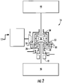
- the lever diagram as shown in FIG. 6 , represents the planetary gear set 214 arrangement according to FIG. 5 is understood by those skilled in the art.
- the electric motor-generator 12, 112, 212 drives the output shaft 22, 122, 222 that drives the bevel gear 24, 124, 224.
- the bevel gear 24, 124, 224 drives the bevel pinion gear 26, 126, 226 that drives the planetary gear set 14, 114, 214.
- the first clutch 50, 150, 250 is engaged to selectively ground a portion of the planetary gear set 14, 114, 214.
- the first clutch 50, 150, 250 is not engaged and the direct drive mode is achieved.
- the second clutch 251 is engaged to ground a portion of the planetary gear set 250.
- the clutches 50, 150 250 are in communication with a control assembly (not shown).
- the clutches 50, 150, 250 may have a separate control assemblies and/or can be in communication with all other vehicle controllers through a SVC. Typically, a separate supervisory controller is required for HEV/FCEV/EV systems.
- the torque is transmitted from the planetary gear set 14, 114, 214 to the differential unit 36, 136, 236 and to the wheel assemblies 44, 144, 244, 46, 146, 246.
- the clutches 50, 150, 250, 251 require a driveline torque interruption from the motor-generator 12, 112, 212 and a synchronous speed match from the motor-generator 12, 112, 212 to allow for engagement of the desired mode of operation or planetary gear ratio.
- This can be accomplished using vehicle sensors (not shown) to send signals to an electric control unit (ECU) (not shown) which controls a pneumatic or electric shift mechanism or actuator included in a controller or a SVC.
- ECU electric control unit
- the ECU can use an algorithm which incorporates motor speed, vehicle speed, grade, gross vehicle weight, acceleration, motor efficiency map, shift mechanism position and other data to determine the optimum motor speed and torque output and determine the required planetary ratio and, thereby, engage clutches 50, 150, 250, 251 respectively to achieve the desired torque output.
- the motor-generator 12, 112, 212, planetary gear set 14, 114, 214 and differential unit 16, 116, 216 are integrated into an electric drive axle 10, 110, 210 which is positioned in the axle center section of a motor vehicle, thereby requiring a minimal package envelope which can be easily adapted to fit existing vehicle chasses and system.
- the motor-generator 12, 112, 212 additionally provides electrical energy during regenerative braking.
- the motor-generator 12, 112, 212 retards portions of the electric drive axle 10, 110, 210, electric energy is generated within the motor-generator 12, 112, 212.
- the electrical energy provided during regenerative braking can be utilized to charge a battery (not shown) connected to the motor-generator 12, 112, 212 through a controller (not shown).
- the electric drive axles 10, 110, 210 can be used in front wheel drive and rear wheel drive vehicles. While not shown, it is understood that the electric axles 10, 110, 210 may be operated with an unpowered tag or pusher axle to form a multi-axle driveline.
- the drive axles 10, 110, 210 disclosed herein are applicable to HEV, EV and Fuel Cell Hybrid systems. It should be understood that electric or hybrid electric vehicles incorporating embodiments of the electric drive axles 10, 110, 210 disclosed herein are capable of including a number of other powertrain components, such as, but not limited to, high-voltage battery pack with a battery management system or ultracapacitor, on-board charger, DC-DC converters, a variety of sensors, actuators, and controllers, among others.
- powertrain components such as, but not limited to, high-voltage battery pack with a battery management system or ultracapacitor, on-board charger, DC-DC converters, a variety of sensors, actuators, and controllers, among others.
Description
- Provided herein is an electric drive axle for a motor vehicle and, more particularly, an electric drive axle having a single electric motor that provides two and three speed configurations.
- There is an increasing interest in hybrid and electric vehicles to reduce carbon emission and reduce air pollution. Exemplary electric drives are known from e.g.
WO 2012/007030 A1 andWO 2012/007031 A1 .WO 2012/007030 A1 shows more specifically an electric drive axle for a motor vehicle comprising an axle housing, an electric motor having an output shaft, a fixed ratio planetary gear arrangement including a sun gear, a ring gear, and a carrier connecting the sun gear and ring gear, a differential unit including a differential gear arrangement housed within a differential case and a first clutch selectively operable to connect the ring gear to a stationary member of the electric drive axle, wherein the sun gear is drivingly connected to the output shaft of the motor and wherein the carrier is in driving engagement with the differential case. An exemplary differential for a motor vehicle is shown inFR 2 864 191 A1 - Current designs for electric drive axles optimize performance by adding additional components to the drivetrains such as additional motors, a multispeed gearbox between the motor and axle, and a hub reduction to achieve a desired overall axle ratio and performance. However, these designs entail adding cost and complexity to the drivetrains.
- Therefore, it would be advantageous to develop an electric drive axle for an electric vehicle that can operate efficiently at both high and low speeds that is cost effect and simple to control.
- Provided herein is an electric drive axle for a motor vehicle,comprising an axle housing, an electric motor having an output shaft directly driven by a bevel pinion gear coupled thereto, a fixed ratio planetary gear set including a sun gear, a ring gear, and a carrier connecting the sun gear and ring gear, a differential unit including a differential gear arrangement housed within a differential case, wherein the carrier is in driving engagement with the differential case, a first clutch configured to selectively couple the sun gear to the bevel pinion gear or to a first stationary member of the electric drive axle (210), and a second clutch configured to selectively couple the ring gear to a second stationary member, wherein the electric drive axle is configured to be operated in a first mode of operation by engaging the first clutch to selectively couple the sun gear to the first stationary member, wherein the electric drive axle is configured to be operated in a second mode of operation by not engaging the first clutch, and wherein the electric drive axle is configured to be operated in a third mode of operation by engaging the second clutch to selectively couple the ring gear to the second stationary member.
- The above, as well as other advantages of the present embodiments, will become readily apparent to those skilled in the art from the following detailed description when considered in the light of the accompanying drawings in which:
-
FIG. 1 is a schematic view of an electric drive axle; -
FIG. 2 is a schematic view of an electric drive axle according to an embodiment which is not part of the invention; -
FIG. 3 is a schematic view of an electric drive axle; -
FIG. 4 is a schematic view of an electric drive axle according to another embodiment which is not part of the invention; -
FIG. 5 is a schematic view of an electric drive axle according to an embodiment of the invention; and -
FIG. 6 is a level diagram of a planetary gear set of the electric drive axle depicted inFIG. 5 . - It is to be understood that the preferred embodiments may assume various alternative orientations and step sequences, except where expressly specified to the contrary. It is also to be understood that the specific devices and processes illustrated in the attached drawings, and described in the following specification are simply exemplary embodiments. Hence, specific dimensions, directions, orientations or other physical characteristics relating to the embodiments disclosed are not to be considered as limiting, unless expressly stated otherwise.
-
FIG. 1 is a schematic view of anelectric drive axle 10 for a motor vehicle according to an embodiment which is not part of the invention. - The
electric drive axle 10 includes a motor-generator 12, a reducingplanetary gear set 14, adifferential unit 16 and two axlehalf shafts electric drive axle 10 includes the fiveassembles axle 10 may include fewer or more assemblies. - The motor-
generator 12 is coupled to an axle housing (not shown). The motor-generator 12 is in electrical communication with a controller (not shown) and an energy storage device (not shown). In some embodiments, the energy storage device can be a battery. Depending on the electrical control of the motor-generator 12 using the controller, the motor-generator 12 may apply force to or retard a portion of theelectric drive axle 10 it is drivingly engaged with. In some embodiments, the motor-generator 12 is positioned within an axle housing. It is to be understood that the battery can be replaced with a fuel cell for a fuel cell electric vehicle drivetrain (FCEV). - As shown in
FIG. 1 , the motor-generator 12 is arranged transversely to axlehalf shafts output shaft 22. Theoutput shaft 22 is drivingly connected to abevel pinion 24. Alternately, thebevel pinion 24 may be integrally formed with theoutput shaft 22. Thebevel pinion 24 meshes with abevel gear 26 drivingly engaged with the reducingplanetary gear set 14. Thebevel gear 26 may be one of a hypoid gear, a spiral bevel gear, a straight bevel gear, or any other gear known to those skilled in the art. In one embodiment, thebevel pinion 24 andbevel gear 26 can provide a gear ratio of 6.5:1, but is not limited thereto. - The
bevel gear 26 is drivingly engaged with theplanetary gear set 14. In one embodiment, theplanetary gear set 14 is integrated into theelectric drive axle 10 and positioned between thebevel gear 26 and the axlehalf shafts planetary gear set 14 is a fixed ratio planetary gear set. Theplanetary gear set 14 is drivingly engaged with thebevel gear 26 and thedifferential unit 16. Theplanetary gear set 14 includes asun gear portion 28, aring gear portion 30 and acarrier portion 32 connecting thesun gear portion 28 and thering gear portion 30. - In further embodiments, the
planetary gear set 14 can include additional reducing gear sets to achieve a desired gear reduction depending on the application theelectric drive axle 10 is used. - As shown in
FIG. 1 , thering gear portion 30 is in driving engagement with the motor-generator 12 via thebevel gear 26. Thecarrier portion 32 is in driving engagement with adifferential case 34 including adifferential gear arrangement 36 of thedifferential unit 16. - In some embodiments, the
differential gear arrangement 36 includes a pair ofpinion gears 38 andside gears 40, 42 rotatably supported in thedifferential case 34. However, other differential gear arrangements including, but not limited to, a planetary differential gear arrangements can also be used. Thedifferential case 34 rotates around a rotational axis Z along with the two axlehalf shafts pinion gears 38 and engage axlehalf shafts half shafts wheel assemblies pinion gears 38 are rotatably supported on apinion shaft 48 secured to thedifferential case 34. Thewheel assemblies electric drive axle 10. - The
sun gear portion 28 is permanently grounded to astationary member 49 of the motor vehicle resulting in the planetary gear set 14 producing a reducing planetary fixed planetary gear ratio. In some embodiments, thestationary member 49 is an axle housing, but is not limited thereto. In one embodiment, thestationary member 49 is positioned between theplanetary gear set 14 and thewheel assembly 46. As a non-limiting example, the planetary gear set may have a gear ratio of 1.4:1. However, it is understood that other reducing gear ratios are possible. It is understood that theplanetary gear set 14 may have other configurations that facilitate a similar operation and the position of thestationary member 49 can vary depending on the arrangement of theplanetary gear set 14. The fixed planetary gear ration provided by theplanetary gear set 14 allows for the size of theelectric motor 12 to be reduced. - Additionally, as shown in
FIG. 2 , in another embodiment which is not part of the invention, theelectric drive axle 10 can include a clutch 50 which selectively grounds thesun gear portion 28 to thestationary member 49 providing a two-speed electric drive axle. When thesun gear portion 28 is grounded, theelectric drive axle 10 provides a first planetary gear ratio and when thesun gear portion 28 is not grounded, theelectric drive axle 10 provides a second planetary gear ratio or a direct drive ratio. In one embodiment, the first planetary gear ratio is 1.4:1, but is not limited thereto. It is understood that the planetary gear set 14 may have other configurations that facilitate a similar operation and the position of thestationary member 49 can vary depending on the arrangement of the planetary gear set 14. - As shown in
FIG. 2 , the clutch 50 is a dog clutch; however, other torque transmitting devices can be used. In some embodiments, the clutch 50 is in communication with an actuator. The actuator can be, but is not limited to, an electromagnetic actuator a pneumatic actuator. The actuator can be controller by the controller and/or a supervisory vehicle control system (SVC). - In some embodiments, the motor-
generator 12, bevel gears 24, 26, planetary gear set 14 anddifferential unit 36 are integrated into a single unit on the axle of the motor vehicle providing a minimal packaging envelope that is easily adaptable to existing motor vehicle chassis and suspension systems. -
Figures 3 and4 illustrate electric dive axles according embodiments which are not part of the invention. The electric drive axles are variations of theelectric drive axle 10 and have similar features thereto. The embodiments shown inFIG. 3 to 5 include similar components to theelectric drive axle 10. Similar features of the embodiment shown inFIG. 3 to 5 are numbered similarly in series. Different and additional features of the variation shown inFIG. 3 to 5 are described hereinbelow and can be appreciated by one skilled in the art in view ofFIG. 1 and the other embodiments illustrated and described in this disclosure. - In another embodiment which is not part of the invention, as shown in
FIG. 3 , thesun gear portion 128 of planetary gear set 114 of theelectric drive axle 110 is drivingly engaged with the motor-generator 112 via thebevel pinion 124 and thebevel gear 126. Thebevel pinion 124 andbevel gear 126 can have a 5:1 bevel gear ratio, but is not limited thereto. Thecarrier portion 132 of planetary gear set 114 is in driving engagement with a portion of thedifferential housing 134 including thedifferential gear arrangement 136. In this arrangement, thering gear portion 130 is permanently grounded to astationary member 149 to produce a fixed planetary gear ratio. In one embodiment, thestationary member 149 is positioned between thedifferential unit 116 and thewheel assembly 144. As a non-limiting example, the fixed planetary gear ratio maybe 4:1. It is understood that the planetary gear set 114 may have other configurations that facilitate a similar operation and the position of thestationary member 149 can vary depending on the arrangement of the planetary gear set 114. - In another embodiment which is not part of the invention, as shown in
FIG. 4 , a clutch 150 can be included in theelectric drive axle 110. The clutch 150 maybe selectively engaged to ground thering portion 130, providing a two-speed electric drive axle. When thering gear portion 130 is grounded, theelectric drive axle 110 provides a first planetary gear ratio and when thering gear portion 130 is not grounded, theelectric drive axle 110 provides a second planetary gear ratio or a direct drive ratio. As a non-limiting example, the first planetary gear ratio maybe 4:1. In the embodiment, as shown inFIG. 4 , the clutch 150 is a dog clutch; however, other torque transmitting devices can be used. - In a preferred embodiment according to the invention, as shown in
FIG. 5 , both thering gear portion 230 and thesun gear portion 228 of the planetary gear set 214 can be selectively grounded usingclutches clutches - In this embodiment, the
sun gear portion 228 is selectively coupled to thebevel gear 226 or grounded to astationary member 247 by afirst clutch 250. In this embodiment, thestationary member 247 is positioned between the planetary gear set 214 and thewheel assembly 246. Thering gear portion 230 is also selectively grounded or coupled to astationary member 249 by asecond clutch 251. In one embodiment, thestationary member 249 is positioned between thedifferential unit 216 and thewheel assembly 244. Both thesun gear portion 228 and thering gear 230 can be selectively grounded byclutches FIG. 5 , theclutches stationary members - In this embodiment, the bevel ratio gear ratio is 5:1; however, it is not limited thereto. When the
sun gear portion 228 only is selectively grounded, a first planetary gear ratio is provided. In one embodiment, the first planetary gear ratio is 1.4:1. When thering gear portion 230 only is selectively grounded, a second planetary gear ratio is provided. In one embodiment, the second planetary gear ratio is 4:1. When neither thering gear portion 230 nor thesun gear portion 228 is grounded, theelectric drive axle 210 is a direct drive mode, i.e. a 1:1 planetary gear ratio. The lever diagram, as shown inFIG. 6 , represents the planetary gear set 214 arrangement according toFIG. 5 is understood by those skilled in the art. - In operation of the
electric drive axle generator output shaft 22, 122, 222 that drives thebevel gear bevel gear bevel pinion gear electric drive axle - To operate the
electric drive axle electric drive axle 210 in a third mode of operation or third gear ratio, thesecond clutch 251 is engaged to ground a portion of the planetary gear set 250. Theclutches 50, 150 250 are in communication with a control assembly (not shown). Theclutches - The torque is transmitted from the planetary gear set 14, 114, 214 to the
differential unit wheel assemblies - The
clutches generator generator clutches - The motor-
generator differential unit electric drive axle - The motor-
generator generator electric drive axle generator generator - The
electric drive axles electric axles - The drive axles 10, 110, 210 disclosed herein are applicable to HEV, EV and Fuel Cell Hybrid systems. It should be understood that electric or hybrid electric vehicles incorporating embodiments of the
electric drive axles - In accordance with the provisions of the patent statutes, the present invention has been described in what is considered to represent its preferred embodiment, however, it should be noted that the embodiment can be practiced otherwise than as specifically illustrated and described without departing from its scope, solely defined by the claims.
Claims (9)
- An electric drive axle (210) for a motor vehicle, comprising:an axle housing;an electric motor (212) having an output shaft directly driven by a bevel pinion gear (224) coupled thereto;a fixed ratio planetary gear set (214) including a sun gear (228), a ring gear (230), and a carrier (232) connecting the sun gear (228) and ring gear (230);a differential unit (216) including a differential gear arrangement housed within a differential case, wherein the carrier (232) is in driving engagement with the differential case;a first clutch (250) configured to selectively couple the sun gear (228) to the bevel pinion gear (224) or to a first stationary member (247) of the electric drive axle (210), anda second clutch (251) configured to selectively couple the ring gear (230) to a second stationary member (249),wherein the electric drive axle (210) is configured to be operated in a first mode of operation by engaging the first clutch (250) to selectively couple the sun gear (228) to the first stationary member (247),wherein the electric drive axle (210) is configured to be operated in a second mode of operation by not engaging the first clutch (250), andwherein the electric drive axle (210) is configured to be operated in a third mode of operation by engaging the second clutch (251) to selectively couple the ring gear (230) to the second stationary member (249).
- The electric drive axle (210) of claim 1, wherein the electric motor (212) is coupled to the axle housing.
- The electric drive axle (10) of claim 1, wherein the differential unit (216) is drivingly engaged with two axle half shafts (18, 20) and the electric motor (212) is positioned transversely to the axle half shafts (18, 20).
- The electric drive axle (10) of claim 1, wherein the fixed ratio planetary gear set (214) is a reducing planetary gear set.
- The electric drive axle (210) of claim 1, wherein the first stationary member (247) and/or the second stationary member (249) is the axle housing.
- The electric drive axle (210) of claim 1, wherein the first clutch (250) is a dog clutch.
- The electric dive axle (210) of claim 1, wherein the electric motor (212) is a motor-generator.
- The electric drive axle (210) of claim 1, wherein the first stationary member (247) is positioned between the planetary gear set (214) and a first axle half shaft connected to the differential unit (216) and the second stationary member (249) is positioned between the planetary gear set (214) and a second axle half shaft connected to the differential unit (216).
- The electric drive axle (210) of claim 1, wherein the first and second clutches (250, 251) are dog clutches.
Applications Claiming Priority (2)
| Application Number | Priority Date | Filing Date | Title |
|---|---|---|---|
| US201662314023P | 2016-03-28 | 2016-03-28 | |
| PCT/US2017/024299 WO2017172614A1 (en) | 2016-03-28 | 2017-03-27 | Single electric motor drive axle with multiple rations |
Publications (2)
| Publication Number | Publication Date |
|---|---|
| EP3436301A1 EP3436301A1 (en) | 2019-02-06 |
| EP3436301B1 true EP3436301B1 (en) | 2022-05-04 |
Family
ID=58489762
Family Applications (1)
| Application Number | Title | Priority Date | Filing Date |
|---|---|---|---|
| EP17716034.8A Active EP3436301B1 (en) | 2016-03-28 | 2017-03-27 | Single electric motor drive axle with multiple ratios |
Country Status (5)
| Country | Link |
|---|---|
| US (2) | US11054009B2 (en) |
| EP (1) | EP3436301B1 (en) |
| JP (1) | JP2019515827A (en) |
| CN (1) | CN108883699B (en) |
| WO (1) | WO2017172614A1 (en) |
Families Citing this family (10)
| Publication number | Priority date | Publication date | Assignee | Title |
|---|---|---|---|---|
| WO2017106620A1 (en) | 2015-12-17 | 2017-06-22 | Axletech International Ip Holdings, Llc | Axle assembly for a vehicle |
| EP3452323B1 (en) | 2016-05-06 | 2021-08-18 | Allison Transmission, Inc. | Axle assembly with electric motor |
| USD821930S1 (en) | 2016-06-06 | 2018-07-03 | Axletech International Ip Holdings, Llc | Gearbox assembly for an axle |
| USD927578S1 (en) | 2018-09-27 | 2021-08-10 | Allison Transmission, Inc. | Axle assembly |
| CN110303880A (en) * | 2019-07-15 | 2019-10-08 | 江苏九龙汽车制造有限公司 | A kind of mini electric vehicle integral electric bridge |
| US11378047B2 (en) * | 2020-01-06 | 2022-07-05 | Schaeffler Technologies AG & Co. KG | Two-speed accessory drive with integrated motor-generator |
| CN114454664A (en) * | 2020-11-10 | 2022-05-10 | 陕西汉德车桥有限公司 | Heavy variable-speed integrated electric drive bridge |
| CN113217601B (en) * | 2021-06-04 | 2022-04-29 | 一汽解放汽车有限公司 | Speed reducer assembly and hybrid drive axle |
| CN113978243B (en) * | 2021-11-11 | 2022-07-15 | 北京吉利学院 | Multifunctional drive axle of car |
| CN115042560B (en) * | 2022-06-27 | 2024-04-12 | 浙江吉利控股集团有限公司 | Automobile and electric drive transmission mechanism thereof |
Citations (2)
| Publication number | Priority date | Publication date | Assignee | Title |
|---|---|---|---|---|
| WO2013089457A1 (en) * | 2011-12-16 | 2013-06-20 | 우영유압주식회사 | Axle device for two step, advance and reverse electrical operation |
| US20140274527A1 (en) * | 2013-03-13 | 2014-09-18 | Eaam Driveline Systems Ab | Drive module having planetary transmission with nested ring gears |
Family Cites Families (70)
| Publication number | Priority date | Publication date | Assignee | Title |
|---|---|---|---|---|
| US1117700A (en) | 1912-07-01 | 1914-11-17 | Piggins Motor Truck Company | Driving-axle for automobiles and trucks. |
| US1258946A (en) | 1916-08-26 | 1918-03-12 | Russel Motor Axle Company | Rear axle. |
| US1373142A (en) | 1919-05-10 | 1921-03-29 | Int Motor Co | Driving mechanism for motor-vehicles |
| US1421836A (en) | 1919-05-29 | 1922-07-04 | Russel Motor Axle Company | Vehicle axle |
| US2689015A (en) | 1951-01-19 | 1954-09-14 | Daimler Benz Ag | Axle suspension for motor vehicles |
| US3011461A (en) | 1957-10-24 | 1961-12-05 | Singer Mfg Co | Seam guides for sewing machines |
| FR2158000A1 (en) | 1971-10-30 | 1973-06-08 | Berkeley Stephens Hender | |
| US4270622A (en) * | 1979-06-27 | 1981-06-02 | Travis James M | Drive axle for electric vehicle |
| US5168946A (en) | 1991-09-09 | 1992-12-08 | General Electric Company | Track-laying vehicle electric drive system |
| US5188195A (en) | 1991-11-12 | 1993-02-23 | Haustein Norman E | Vehicle driving wheel suspension system |
| US5718300A (en) | 1995-05-15 | 1998-02-17 | New Venture Gear, Inc. | Electric vehicle final drive |
| FR2746352B1 (en) | 1996-03-22 | 1998-05-29 | Paganelli Gino | ELECTRIC MOTOR VEHICLE WITH BACK-UP HEAT MOTOR |
| US5845731A (en) | 1996-07-02 | 1998-12-08 | Chrysler Corporation | Hybrid motor vehicle |
| US6276474B1 (en) | 1997-02-18 | 2001-08-21 | Rockwell Heavy Vehicle Systems, Inc. | Low floor drive unit assembly for an electrically driven vehicle |
| AU9659898A (en) | 1997-10-21 | 1999-05-10 | Stridsberg Innovation Ab | A hybrid powertrain |
| US6295487B1 (en) | 1998-07-21 | 2001-09-25 | Tokyo R & D Co., Ltd. | Hybrid vehicle and method of controlling the travel of the vehicle |
| US6295847B1 (en) | 1999-10-22 | 2001-10-02 | Acco Brands, Inc. | Cable locking device |
| US6455947B1 (en) | 2001-02-14 | 2002-09-24 | Bae Systems Controls, Inc. | Power combining apparatus for hybrid electric vehicle |
| US6644427B2 (en) | 2001-04-06 | 2003-11-11 | Ise Research Corporation | System and method for providing parallel power in a hybrid-electric vehicle |
| GB0109338D0 (en) | 2001-04-17 | 2001-05-30 | Secr Defence | Drive configuration for a skid steered vehicle |
| US6644247B2 (en) | 2001-08-08 | 2003-11-11 | General Electric Company | Frequency switching systems for portable power modules |
| US7000717B2 (en) | 2001-10-23 | 2006-02-21 | The Timken Company | Output power split hybrid electric drive system |
| US20030111280A1 (en) | 2001-12-19 | 2003-06-19 | Platner David K. | Drive system for an electric vehicle |
| US7174978B2 (en) | 2002-03-29 | 2007-02-13 | Aisin Aw Co., Ltd. | Hybrid drive unit, and front-engine/rear-drive type automobile having the hybrid drive unit mounted thereon |
| US7520354B2 (en) | 2002-05-02 | 2009-04-21 | Oshkosh Truck Corporation | Hybrid vehicle with combustion engine/electric motor drive |
| US6935451B2 (en) | 2002-10-29 | 2005-08-30 | Arvinmeritor Technology, Llc | Axle assembly with parallel drive system for electric hybrid vehicles |
| US7028583B2 (en) | 2003-07-30 | 2006-04-18 | Arvinmeritor Technology, Llc | Axle assembly with transverse mounted electric motors |
| JP4088574B2 (en) | 2003-09-05 | 2008-05-21 | トヨタ自動車株式会社 | Power output device and automobile equipped with the same |
| US7140461B2 (en) | 2003-11-26 | 2006-11-28 | Oshkosh Truck Corporation | Power splitting vehicle drive system |
| FR2864191B1 (en) * | 2003-12-19 | 2006-02-17 | Peugeot Citroen Automobiles Sa | DIFFERENTIAL ASYMMETRIC DISSIPATIVE DOUBLE CLUTCH EXCENTRE, FOR MOTOR VEHICLE |
| WO2005081930A2 (en) | 2004-02-24 | 2005-09-09 | Polymer Aging Concepts, Inc. | Heath monitoring method and apparatus for composite materials |
| US7410017B2 (en) | 2004-11-30 | 2008-08-12 | The Timken Company | Electric drive axle |
| US7497286B2 (en) | 2005-07-29 | 2009-03-03 | Borgwarner Inc. | Auxiliary electric drive assembly |
| JP4188348B2 (en) | 2005-08-10 | 2008-11-26 | 株式会社日立製作所 | ELECTRIC VEHICLE TRAVEL CONTROL DEVICE AND ELECTRIC TRAVEL CONTROL SYSTEM |
| GB0518396D0 (en) | 2005-09-09 | 2005-10-19 | Longchamp Gerard | Fender arrangement for trucks |
| DE102005044181A1 (en) | 2005-09-15 | 2007-04-19 | Deere & Company, Moline | Drive system for a vehicle and an agricultural utility vehicle |
| DE102005062874A1 (en) | 2005-12-29 | 2007-07-05 | Robert Bosch Gmbh | Electromagnetic high frequency signal transmitting and/or receiving device e.g. radar antenna, for hand tool device, has two antenna sections, which are arranged adjacent to one another and connected with one another by resistance units |
| WO2007131849A1 (en) * | 2006-05-16 | 2007-11-22 | Zf Friedrichshafen Ag | Actuating mechanism for a clutch |
| EP2086781B1 (en) | 2006-12-08 | 2013-05-01 | Byd Company Limited | Hybrid power output system |
| CN101209667A (en) | 2006-12-25 | 2008-07-02 | 比亚迪股份有限公司 | Mixed power outputting device |
| JP4297948B2 (en) | 2007-04-13 | 2009-07-15 | トヨタ自動車株式会社 | Hybrid drive apparatus and control method thereof |
| US8186219B2 (en) | 2007-08-23 | 2012-05-29 | Sagem Defense Securite | Method of determining a speed of rotation of an axially symmetrical vibrating sensor, and a corresponding inertial device |
| US8011461B2 (en) | 2008-02-14 | 2011-09-06 | Illinois Institute Of Technology | Hybrid electric conversion kit for rear-wheel drive, all wheel drive, and four wheel drive vehicles |
| US8091677B2 (en) | 2008-03-27 | 2012-01-10 | GM Global Technology Operations LLC | System and method of differentiating rotational speed and torque between wheels of a hybrid vehicle |
| DE102008030581A1 (en) | 2008-06-27 | 2009-12-31 | Daimler Ag | Drive train for a motor vehicle and method for operating a drive train of a motor vehicle |
| US7739005B1 (en) | 2009-02-26 | 2010-06-15 | Tesla Motors, Inc. | Control system for an all-wheel drive electric vehicle |
| US8453770B2 (en) | 2009-01-29 | 2013-06-04 | Tesla Motors, Inc. | Dual motor drive and control system for an electric vehicle |
| CN101544178A (en) | 2009-05-12 | 2009-09-30 | 奇瑞汽车股份有限公司 | Power assembly system of electric vehicle |
| DE102010004228A1 (en) | 2010-01-09 | 2011-07-14 | IAV GmbH Ingenieurgesellschaft Auto und Verkehr, 10587 | Device for driving a vehicle |
| DE102010017966A1 (en) | 2010-04-23 | 2011-10-27 | Dr. Ing. H.C. F. Porsche Aktiengesellschaft | Vehicle with electric drive |
| US8708074B1 (en) | 2010-06-15 | 2014-04-29 | Hydro-Gear Limited Partnership | Selectable four-wheel drive system |
| DE112010005738B4 (en) * | 2010-07-13 | 2022-01-13 | Gkn Automotive Limited | Electric drive for a motor vehicle |
| WO2012007031A1 (en) * | 2010-07-13 | 2012-01-19 | Gkn Driveline International Gmbh | Electric drive for a motor vehicle |
| US8998765B2 (en) * | 2010-07-14 | 2015-04-07 | E-Aam Driveline Systems Ab | Axle assembly with torque distribution drive mechanism |
| KR20120117518A (en) | 2011-04-15 | 2012-10-24 | 박계정 | A transmission system and control method thereof |
| US20140116793A1 (en) | 2011-06-09 | 2014-05-01 | Prevost, Une Division De Groupe Volvo Canada Inc. | Hybrid vehicle |
| EP2574491B1 (en) | 2011-09-30 | 2018-12-26 | Iveco S.p.A. | Support device of an adjustable vehicular display integrated in the dashboard of a vehicle, in particular an industrial or commercial vehicle |
| US8651994B2 (en) | 2011-09-30 | 2014-02-18 | Arvinmeritor Technology, Llc | Drive axle assembly and disengagement system |
| KR20130066225A (en) | 2011-12-12 | 2013-06-20 | 현대자동차주식회사 | Power structure of hybrid system |
| US9139079B2 (en) * | 2012-03-26 | 2015-09-22 | Mcmaster University | Integrated electro-mechanical powertrain system for hybrid vehicles |
| CN202573795U (en) | 2012-05-31 | 2012-12-05 | 石传龙 | Two-gear drive device for electric car |
| ES2660552T3 (en) | 2012-09-06 | 2018-03-22 | Iveco S.P.A. | Vehicle comprising a torque distributor for two axes, method to control the same, computer program and media that can be read by a computer |
| CN104812604B (en) | 2012-11-27 | 2017-12-19 | 丰田自动车株式会社 | The control device of motor vehicle driven by mixed power |
| US9062744B2 (en) | 2013-03-13 | 2015-06-23 | American Axle & Manufacturing, Inc. | Two-speed drive module |
| RU2014109689A (en) * | 2013-03-15 | 2015-09-20 | е-ААМ Драйвлайн системз АБ | BRIDGE ASSEMBLY WITH TORQUE DISTRIBUTION MECHANISM |
| EP2851227B1 (en) * | 2013-09-24 | 2017-05-17 | Volvo Car Corporation | A rear drive unit for a hybrid electric motor vehicle |
| WO2015113415A1 (en) | 2014-01-30 | 2015-08-06 | Byd Company Limited | Power transmission system for vehicle and vehicle comprising the same |
| WO2015113414A1 (en) | 2014-01-30 | 2015-08-06 | Byd Company Limited | Power transmission system for vehicle and vehicle comprising the same |
| CA2893535C (en) | 2015-06-03 | 2022-08-09 | Benoit Boulet | Seamless two-speed transmission for electric vehicle |
| US9637127B1 (en) * | 2015-12-29 | 2017-05-02 | Dana Automotive Systems Group, Llc | Two-speed electric drive unit |
-
2017
- 2017-03-27 WO PCT/US2017/024299 patent/WO2017172614A1/en active Application Filing
- 2017-03-27 JP JP2018550325A patent/JP2019515827A/en not_active Ceased
- 2017-03-27 CN CN201780019124.6A patent/CN108883699B/en active Active
- 2017-03-27 EP EP17716034.8A patent/EP3436301B1/en active Active
- 2017-03-27 US US16/088,193 patent/US11054009B2/en active Active
-
2021
- 2021-06-08 US US17/342,369 patent/US11460096B2/en active Active
Patent Citations (2)
| Publication number | Priority date | Publication date | Assignee | Title |
|---|---|---|---|---|
| WO2013089457A1 (en) * | 2011-12-16 | 2013-06-20 | 우영유압주식회사 | Axle device for two step, advance and reverse electrical operation |
| US20140274527A1 (en) * | 2013-03-13 | 2014-09-18 | Eaam Driveline Systems Ab | Drive module having planetary transmission with nested ring gears |
Also Published As
| Publication number | Publication date |
|---|---|
| EP3436301A1 (en) | 2019-02-06 |
| JP2019515827A (en) | 2019-06-13 |
| CN108883699B (en) | 2022-02-11 |
| WO2017172614A8 (en) | 2018-08-16 |
| US11460096B2 (en) | 2022-10-04 |
| WO2017172614A1 (en) | 2017-10-05 |
| US20210293314A1 (en) | 2021-09-23 |
| US20200300346A1 (en) | 2020-09-24 |
| US11054009B2 (en) | 2021-07-06 |
| CN108883699A (en) | 2018-11-23 |
Similar Documents
| Publication | Publication Date | Title |
|---|---|---|
| US11460096B2 (en) | Single electric motor drive axle with multiple ratios | |
| CN109996695B (en) | Electric vehicle and hybrid electric vehicle electric axle transmission | |
| EP3436299B1 (en) | Electric drivetrain axles with multi-speed gearboxes | |
| US11376951B2 (en) | Continuously variable electric axles with on-demand energy harvesting capabilities for secondary or tag E-axles | |
| EP2522541B1 (en) | Front-and-rear-wheel drive vehicle | |
| US11926206B2 (en) | Hybrid electric vehicle axle with two motors | |
| US11639094B2 (en) | Distributed drivetrain architectures for commercial vehicles with a hybrid electric powertrain and dual range disconnect axles | |
| CN108058593B (en) | Driving mechanism and automobile | |
| US11433765B2 (en) | Commercial vehicle with electric driven axle | |
| US10801598B2 (en) | Hybrid axle drive with torque vectoring | |
| WO2010151579A1 (en) | Drive configurations for high speed motor drive systems | |
| US10486521B2 (en) | Distributed drivetrain architectures for commercial vehicles with a hybrid electric powertrain | |
| WO2018222988A1 (en) | An axlie assembly | |
| CN110949111A (en) | Double-rotor motor and Ravigna type planetary gear train series type automobile hybrid power system | |
| CN106915247B (en) | Hybrid power system and vehicle with same | |
| CN107054043B (en) | Power transmission system, vehicle with power transmission system and method for controlling vehicle | |
| CN102442189B (en) | Double-motor coupling driving system |
Legal Events
| Date | Code | Title | Description |
|---|---|---|---|
| STAA | Information on the status of an ep patent application or granted ep patent |
Free format text: STATUS: UNKNOWN |
|
| STAA | Information on the status of an ep patent application or granted ep patent |
Free format text: STATUS: THE INTERNATIONAL PUBLICATION HAS BEEN MADE |
|
| PUAI | Public reference made under article 153(3) epc to a published international application that has entered the european phase |
Free format text: ORIGINAL CODE: 0009012 |
|
| STAA | Information on the status of an ep patent application or granted ep patent |
Free format text: STATUS: REQUEST FOR EXAMINATION WAS MADE |
|
| 17P | Request for examination filed |
Effective date: 20180924 |
|
| AK | Designated contracting states |
Kind code of ref document: A1 Designated state(s): AL AT BE BG CH CY CZ DE DK EE ES FI FR GB GR HR HU IE IS IT LI LT LU LV MC MK MT NL NO PL PT RO RS SE SI SK SM TR |
|
| AX | Request for extension of the european patent |
Extension state: BA ME |
|
| DAV | Request for validation of the european patent (deleted) | ||
| DAX | Request for extension of the european patent (deleted) | ||
| STAA | Information on the status of an ep patent application or granted ep patent |
Free format text: STATUS: EXAMINATION IS IN PROGRESS |
|
| STAA | Information on the status of an ep patent application or granted ep patent |
Free format text: STATUS: EXAMINATION IS IN PROGRESS |
|
| 17Q | First examination report despatched |
Effective date: 20201021 |
|
| REG | Reference to a national code |
Ref country code: DE Ref legal event code: R079 Ref document number: 602017056874 Country of ref document: DE Free format text: PREVIOUS MAIN CLASS: B60K0017040000 Ipc: B60K0017080000 |
|
| GRAP | Despatch of communication of intention to grant a patent |
Free format text: ORIGINAL CODE: EPIDOSNIGR1 |
|
| STAA | Information on the status of an ep patent application or granted ep patent |
Free format text: STATUS: GRANT OF PATENT IS INTENDED |
|
| RIC1 | Information provided on ipc code assigned before grant |
Ipc: B60K 17/08 20060101AFI20211004BHEP |
|
| INTG | Intention to grant announced |
Effective date: 20211022 |
|
| GRAS | Grant fee paid |
Free format text: ORIGINAL CODE: EPIDOSNIGR3 |
|
| GRAA | (expected) grant |
Free format text: ORIGINAL CODE: 0009210 |
|
| STAA | Information on the status of an ep patent application or granted ep patent |
Free format text: STATUS: THE PATENT HAS BEEN GRANTED |
|
| AK | Designated contracting states |
Kind code of ref document: B1 Designated state(s): AL AT BE BG CH CY CZ DE DK EE ES FI FR GB GR HR HU IE IS IT LI LT LU LV MC MK MT NL NO PL PT RO RS SE SI SK SM TR |
|
| REG | Reference to a national code |
Ref country code: GB Ref legal event code: FG4D |
|
| REG | Reference to a national code |
Ref country code: CH Ref legal event code: EP |
|
| REG | Reference to a national code |
Ref country code: AT Ref legal event code: REF Ref document number: 1488690 Country of ref document: AT Kind code of ref document: T Effective date: 20220515 |
|
| REG | Reference to a national code |
Ref country code: IE Ref legal event code: FG4D Ref country code: DE Ref legal event code: R096 Ref document number: 602017056874 Country of ref document: DE |
|
| REG | Reference to a national code |
Ref country code: LT Ref legal event code: MG9D |
|
| REG | Reference to a national code |
Ref country code: NL Ref legal event code: MP Effective date: 20220504 |
|
| REG | Reference to a national code |
Ref country code: AT Ref legal event code: MK05 Ref document number: 1488690 Country of ref document: AT Kind code of ref document: T Effective date: 20220504 |
|
| PG25 | Lapsed in a contracting state [announced via postgrant information from national office to epo] |
Ref country code: SE Free format text: LAPSE BECAUSE OF FAILURE TO SUBMIT A TRANSLATION OF THE DESCRIPTION OR TO PAY THE FEE WITHIN THE PRESCRIBED TIME-LIMIT Effective date: 20220504 Ref country code: PT Free format text: LAPSE BECAUSE OF FAILURE TO SUBMIT A TRANSLATION OF THE DESCRIPTION OR TO PAY THE FEE WITHIN THE PRESCRIBED TIME-LIMIT Effective date: 20220905 Ref country code: NO Free format text: LAPSE BECAUSE OF FAILURE TO SUBMIT A TRANSLATION OF THE DESCRIPTION OR TO PAY THE FEE WITHIN THE PRESCRIBED TIME-LIMIT Effective date: 20220804 Ref country code: NL Free format text: LAPSE BECAUSE OF FAILURE TO SUBMIT A TRANSLATION OF THE DESCRIPTION OR TO PAY THE FEE WITHIN THE PRESCRIBED TIME-LIMIT Effective date: 20220504 Ref country code: LT Free format text: LAPSE BECAUSE OF FAILURE TO SUBMIT A TRANSLATION OF THE DESCRIPTION OR TO PAY THE FEE WITHIN THE PRESCRIBED TIME-LIMIT Effective date: 20220504 Ref country code: HR Free format text: LAPSE BECAUSE OF FAILURE TO SUBMIT A TRANSLATION OF THE DESCRIPTION OR TO PAY THE FEE WITHIN THE PRESCRIBED TIME-LIMIT Effective date: 20220504 Ref country code: GR Free format text: LAPSE BECAUSE OF FAILURE TO SUBMIT A TRANSLATION OF THE DESCRIPTION OR TO PAY THE FEE WITHIN THE PRESCRIBED TIME-LIMIT Effective date: 20220805 Ref country code: FI Free format text: LAPSE BECAUSE OF FAILURE TO SUBMIT A TRANSLATION OF THE DESCRIPTION OR TO PAY THE FEE WITHIN THE PRESCRIBED TIME-LIMIT Effective date: 20220504 Ref country code: ES Free format text: LAPSE BECAUSE OF FAILURE TO SUBMIT A TRANSLATION OF THE DESCRIPTION OR TO PAY THE FEE WITHIN THE PRESCRIBED TIME-LIMIT Effective date: 20220504 Ref country code: BG Free format text: LAPSE BECAUSE OF FAILURE TO SUBMIT A TRANSLATION OF THE DESCRIPTION OR TO PAY THE FEE WITHIN THE PRESCRIBED TIME-LIMIT Effective date: 20220804 Ref country code: AT Free format text: LAPSE BECAUSE OF FAILURE TO SUBMIT A TRANSLATION OF THE DESCRIPTION OR TO PAY THE FEE WITHIN THE PRESCRIBED TIME-LIMIT Effective date: 20220504 |
|
| PG25 | Lapsed in a contracting state [announced via postgrant information from national office to epo] |
Ref country code: RS Free format text: LAPSE BECAUSE OF FAILURE TO SUBMIT A TRANSLATION OF THE DESCRIPTION OR TO PAY THE FEE WITHIN THE PRESCRIBED TIME-LIMIT Effective date: 20220504 Ref country code: PL Free format text: LAPSE BECAUSE OF FAILURE TO SUBMIT A TRANSLATION OF THE DESCRIPTION OR TO PAY THE FEE WITHIN THE PRESCRIBED TIME-LIMIT Effective date: 20220504 Ref country code: LV Free format text: LAPSE BECAUSE OF FAILURE TO SUBMIT A TRANSLATION OF THE DESCRIPTION OR TO PAY THE FEE WITHIN THE PRESCRIBED TIME-LIMIT Effective date: 20220504 Ref country code: IS Free format text: LAPSE BECAUSE OF FAILURE TO SUBMIT A TRANSLATION OF THE DESCRIPTION OR TO PAY THE FEE WITHIN THE PRESCRIBED TIME-LIMIT Effective date: 20220904 |
|
| PG25 | Lapsed in a contracting state [announced via postgrant information from national office to epo] |
Ref country code: SM Free format text: LAPSE BECAUSE OF FAILURE TO SUBMIT A TRANSLATION OF THE DESCRIPTION OR TO PAY THE FEE WITHIN THE PRESCRIBED TIME-LIMIT Effective date: 20220504 Ref country code: SK Free format text: LAPSE BECAUSE OF FAILURE TO SUBMIT A TRANSLATION OF THE DESCRIPTION OR TO PAY THE FEE WITHIN THE PRESCRIBED TIME-LIMIT Effective date: 20220504 Ref country code: RO Free format text: LAPSE BECAUSE OF FAILURE TO SUBMIT A TRANSLATION OF THE DESCRIPTION OR TO PAY THE FEE WITHIN THE PRESCRIBED TIME-LIMIT Effective date: 20220504 Ref country code: EE Free format text: LAPSE BECAUSE OF FAILURE TO SUBMIT A TRANSLATION OF THE DESCRIPTION OR TO PAY THE FEE WITHIN THE PRESCRIBED TIME-LIMIT Effective date: 20220504 Ref country code: DK Free format text: LAPSE BECAUSE OF FAILURE TO SUBMIT A TRANSLATION OF THE DESCRIPTION OR TO PAY THE FEE WITHIN THE PRESCRIBED TIME-LIMIT Effective date: 20220504 Ref country code: CZ Free format text: LAPSE BECAUSE OF FAILURE TO SUBMIT A TRANSLATION OF THE DESCRIPTION OR TO PAY THE FEE WITHIN THE PRESCRIBED TIME-LIMIT Effective date: 20220504 |
|
| REG | Reference to a national code |
Ref country code: DE Ref legal event code: R097 Ref document number: 602017056874 Country of ref document: DE |
|
| PLBE | No opposition filed within time limit |
Free format text: ORIGINAL CODE: 0009261 |
|
| STAA | Information on the status of an ep patent application or granted ep patent |
Free format text: STATUS: NO OPPOSITION FILED WITHIN TIME LIMIT |
|
| PG25 | Lapsed in a contracting state [announced via postgrant information from national office to epo] |
Ref country code: AL Free format text: LAPSE BECAUSE OF FAILURE TO SUBMIT A TRANSLATION OF THE DESCRIPTION OR TO PAY THE FEE WITHIN THE PRESCRIBED TIME-LIMIT Effective date: 20220504 |
|
| 26N | No opposition filed |
Effective date: 20230207 |
|
| PG25 | Lapsed in a contracting state [announced via postgrant information from national office to epo] |
Ref country code: SI Free format text: LAPSE BECAUSE OF FAILURE TO SUBMIT A TRANSLATION OF THE DESCRIPTION OR TO PAY THE FEE WITHIN THE PRESCRIBED TIME-LIMIT Effective date: 20220504 |
|
| PGFP | Annual fee paid to national office [announced via postgrant information from national office to epo] |
Ref country code: DE Payment date: 20230221 Year of fee payment: 7 |
|
| P01 | Opt-out of the competence of the unified patent court (upc) registered |
Effective date: 20230523 |
|
| PG25 | Lapsed in a contracting state [announced via postgrant information from national office to epo] |
Ref country code: MC Free format text: LAPSE BECAUSE OF FAILURE TO SUBMIT A TRANSLATION OF THE DESCRIPTION OR TO PAY THE FEE WITHIN THE PRESCRIBED TIME-LIMIT Effective date: 20220504 |
|
| REG | Reference to a national code |
Ref country code: CH Ref legal event code: PL |
|
| GBPC | Gb: european patent ceased through non-payment of renewal fee |
Effective date: 20230327 |
|
| REG | Reference to a national code |
Ref country code: BE Ref legal event code: MM Effective date: 20230331 |
|
| PG25 | Lapsed in a contracting state [announced via postgrant information from national office to epo] |
Ref country code: LU Free format text: LAPSE BECAUSE OF NON-PAYMENT OF DUE FEES Effective date: 20230327 |
|
| REG | Reference to a national code |
Ref country code: IE Ref legal event code: MM4A |
|
| PG25 | Lapsed in a contracting state [announced via postgrant information from national office to epo] |
Ref country code: GB Free format text: LAPSE BECAUSE OF NON-PAYMENT OF DUE FEES Effective date: 20230327 |
|
| PG25 | Lapsed in a contracting state [announced via postgrant information from national office to epo] |
Ref country code: LI Free format text: LAPSE BECAUSE OF NON-PAYMENT OF DUE FEES Effective date: 20230331 Ref country code: IT Free format text: LAPSE BECAUSE OF FAILURE TO SUBMIT A TRANSLATION OF THE DESCRIPTION OR TO PAY THE FEE WITHIN THE PRESCRIBED TIME-LIMIT Effective date: 20220504 Ref country code: IE Free format text: LAPSE BECAUSE OF NON-PAYMENT OF DUE FEES Effective date: 20230327 Ref country code: GB Free format text: LAPSE BECAUSE OF NON-PAYMENT OF DUE FEES Effective date: 20230327 Ref country code: FR Free format text: LAPSE BECAUSE OF NON-PAYMENT OF DUE FEES Effective date: 20230331 Ref country code: CH Free format text: LAPSE BECAUSE OF NON-PAYMENT OF DUE FEES Effective date: 20230331 |
|
| PG25 | Lapsed in a contracting state [announced via postgrant information from national office to epo] |
Ref country code: BE Free format text: LAPSE BECAUSE OF NON-PAYMENT OF DUE FEES Effective date: 20230331 |