EP3435858B1 - Geräte zur beurteilung von myokardinfarktgewebe durch messung der elektrischen impedanz während des herzzyklus - Google Patents
Geräte zur beurteilung von myokardinfarktgewebe durch messung der elektrischen impedanz während des herzzyklus Download PDFInfo
- Publication number
- EP3435858B1 EP3435858B1 EP16712341.3A EP16712341A EP3435858B1 EP 3435858 B1 EP3435858 B1 EP 3435858B1 EP 16712341 A EP16712341 A EP 16712341A EP 3435858 B1 EP3435858 B1 EP 3435858B1
- Authority
- EP
- European Patent Office
- Prior art keywords
- impedance
- tissue
- signals
- cardiac tissue
- measurement locations
- Prior art date
- Legal status (The legal status is an assumption and is not a legal conclusion. Google has not performed a legal analysis and makes no representation as to the accuracy of the status listed.)
- Active
Links
Images












Classifications
-
- A—HUMAN NECESSITIES
- A61—MEDICAL OR VETERINARY SCIENCE; HYGIENE
- A61B—DIAGNOSIS; SURGERY; IDENTIFICATION
- A61B5/00—Measuring for diagnostic purposes; Identification of persons
- A61B5/68—Arrangements of detecting, measuring or recording means, e.g. sensors, in relation to patient
- A61B5/6846—Arrangements of detecting, measuring or recording means, e.g. sensors, in relation to patient specially adapted to be brought in contact with an internal body part, i.e. invasive
- A61B5/6847—Arrangements of detecting, measuring or recording means, e.g. sensors, in relation to patient specially adapted to be brought in contact with an internal body part, i.e. invasive mounted on an invasive device
- A61B5/6852—Catheters
-
- A—HUMAN NECESSITIES
- A61—MEDICAL OR VETERINARY SCIENCE; HYGIENE
- A61B—DIAGNOSIS; SURGERY; IDENTIFICATION
- A61B5/00—Measuring for diagnostic purposes; Identification of persons
- A61B5/24—Detecting, measuring or recording bioelectric or biomagnetic signals of the body or parts thereof
- A61B5/25—Bioelectric electrodes therefor
- A61B5/279—Bioelectric electrodes therefor specially adapted for particular uses
- A61B5/28—Bioelectric electrodes therefor specially adapted for particular uses for electrocardiography [ECG]
- A61B5/283—Invasive
- A61B5/287—Holders for multiple electrodes, e.g. electrode catheters for electrophysiological study [EPS]
-
- A—HUMAN NECESSITIES
- A61—MEDICAL OR VETERINARY SCIENCE; HYGIENE
- A61B—DIAGNOSIS; SURGERY; IDENTIFICATION
- A61B5/00—Measuring for diagnostic purposes; Identification of persons
- A61B5/02—Detecting, measuring or recording for evaluating the cardiovascular system, e.g. pulse, heart rate, blood pressure or blood flow
- A61B5/021—Measuring pressure in heart or blood vessels
- A61B5/0215—Measuring pressure in heart or blood vessels by means inserted into the body
-
- A—HUMAN NECESSITIES
- A61—MEDICAL OR VETERINARY SCIENCE; HYGIENE
- A61B—DIAGNOSIS; SURGERY; IDENTIFICATION
- A61B5/00—Measuring for diagnostic purposes; Identification of persons
- A61B5/02—Detecting, measuring or recording for evaluating the cardiovascular system, e.g. pulse, heart rate, blood pressure or blood flow
- A61B5/026—Measuring blood flow
- A61B5/029—Measuring blood output from the heart, e.g. minute volume
-
- A—HUMAN NECESSITIES
- A61—MEDICAL OR VETERINARY SCIENCE; HYGIENE
- A61B—DIAGNOSIS; SURGERY; IDENTIFICATION
- A61B5/00—Measuring for diagnostic purposes; Identification of persons
- A61B5/05—Detecting, measuring or recording for diagnosis by means of electric currents or magnetic fields; Measuring using microwaves or radio waves
- A61B5/053—Measuring electrical impedance or conductance of a portion of the body
- A61B5/0538—Measuring electrical impedance or conductance of a portion of the body invasively, e.g. using a catheter
-
- A—HUMAN NECESSITIES
- A61—MEDICAL OR VETERINARY SCIENCE; HYGIENE
- A61B—DIAGNOSIS; SURGERY; IDENTIFICATION
- A61B5/00—Measuring for diagnostic purposes; Identification of persons
- A61B5/24—Detecting, measuring or recording bioelectric or biomagnetic signals of the body or parts thereof
- A61B5/316—Modalities, i.e. specific diagnostic methods
- A61B5/318—Heart-related electrical modalities, e.g. electrocardiography [ECG]
- A61B5/346—Analysis of electrocardiograms
- A61B5/349—Detecting specific parameters of the electrocardiograph cycle
- A61B5/361—Detecting fibrillation
-
- A—HUMAN NECESSITIES
- A61—MEDICAL OR VETERINARY SCIENCE; HYGIENE
- A61B—DIAGNOSIS; SURGERY; IDENTIFICATION
- A61B18/00—Surgical instruments, devices or methods for transferring non-mechanical forms of energy to or from the body
- A61B18/04—Surgical instruments, devices or methods for transferring non-mechanical forms of energy to or from the body by heating
- A61B18/12—Surgical instruments, devices or methods for transferring non-mechanical forms of energy to or from the body by heating by passing a current through the tissue to be heated, e.g. high-frequency current
- A61B18/14—Probes or electrodes therefor
- A61B18/1492—Probes or electrodes therefor having a flexible, catheter-like structure, e.g. for heart ablation
-
- A—HUMAN NECESSITIES
- A61—MEDICAL OR VETERINARY SCIENCE; HYGIENE
- A61B—DIAGNOSIS; SURGERY; IDENTIFICATION
- A61B2505/00—Evaluating, monitoring or diagnosing in the context of a particular type of medical care
- A61B2505/05—Surgical care
-
- A—HUMAN NECESSITIES
- A61—MEDICAL OR VETERINARY SCIENCE; HYGIENE
- A61B—DIAGNOSIS; SURGERY; IDENTIFICATION
- A61B5/00—Measuring for diagnostic purposes; Identification of persons
- A61B5/02—Detecting, measuring or recording for evaluating the cardiovascular system, e.g. pulse, heart rate, blood pressure or blood flow
- A61B5/02007—Evaluating blood vessel condition, e.g. elasticity, compliance
-
- A—HUMAN NECESSITIES
- A61—MEDICAL OR VETERINARY SCIENCE; HYGIENE
- A61B—DIAGNOSIS; SURGERY; IDENTIFICATION
- A61B5/00—Measuring for diagnostic purposes; Identification of persons
- A61B5/06—Devices, other than using radiation, for detecting or locating foreign bodies ; Determining position of diagnostic devices within or on the body of the patient
- A61B5/061—Determining position of a probe within the body employing means separate from the probe, e.g. sensing internal probe position employing impedance electrodes on the surface of the body
-
- A—HUMAN NECESSITIES
- A61—MEDICAL OR VETERINARY SCIENCE; HYGIENE
- A61B—DIAGNOSIS; SURGERY; IDENTIFICATION
- A61B5/00—Measuring for diagnostic purposes; Identification of persons
- A61B5/103—Measuring devices for testing the shape, pattern, colour, size or movement of the body or parts thereof, for diagnostic purposes
- A61B5/107—Measuring physical dimensions, e.g. size of the entire body or parts thereof
-
- A—HUMAN NECESSITIES
- A61—MEDICAL OR VETERINARY SCIENCE; HYGIENE
- A61B—DIAGNOSIS; SURGERY; IDENTIFICATION
- A61B5/00—Measuring for diagnostic purposes; Identification of persons
- A61B5/24—Detecting, measuring or recording bioelectric or biomagnetic signals of the body or parts thereof
- A61B5/316—Modalities, i.e. specific diagnostic methods
- A61B5/318—Heart-related electrical modalities, e.g. electrocardiography [ECG]
- A61B5/346—Analysis of electrocardiograms
- A61B5/349—Detecting specific parameters of the electrocardiograph cycle
- A61B5/363—Detecting tachycardia or bradycardia
Definitions
- the present disclosure relates to devices to assess infarcted tissue by measuring electrical impedance. More specifically, the devices may be used to recognize the extent and deepness of an infarcted tissue, such as for example myocardial infarcted tissue.
- Ventricular arrhythmias are responsible of approximately 60% of sudden deaths in patients with a previously cardiac infarction. Radiofrequency ablation of the arrhythmogenic foci is able to treat around 50-80% of the patients with postinfarction ventricular arrhythmias. The success rate of this procedure could be increased by improvements in the identification and localization of the arrhythmogenic foci in the clinical practice.
- the clinical intracardiac navigation systems used nowadays for example: (i) CARTO®, provided by Biosence Webster®, (ii) NavXTM, provided by St. Jude MedicalTM , or (iii) RhythmiaTM, provided by Boston ScientificTM) locate the postinfarction scar by local measures of voltage using intracavitary electrocatheters. A major drawback of the voltage measurements is that they cannot determine if the scar is completely transmural or not. Another drawback is that these voltage measurements depend on the wave front activation pattern, that can change if the patient suffers and ectopic arrhythmic episode.
- the characterization of biological substrates by means of electrical impedance provides relevant physiological information about the pathological status of the tissues. It has been reported that normal and infarcted myocardium can be recognized by measuring the myocardial electrical impedance (module and phase angle) using an intracardiac electrocatheter, see e.g. " Warren M, et al. Percutaneous electrocatheter technique for on-line detection of healed transmural myocardial infarction. Pacing Clin Electrophysiol. 2000;23:1283-1287 " (Warren 2000'). As compared with the normal myocardium, the necrotic infarct scar shows a lower impedance module and a flat phase angle deviation.
- Tachycardia-related channel in the scar tissue in patients with sustained monomorphic ventricular tachycardias Influence of the voltage scar definition. Circulation 2004;110:2568-2574 .; Nakahara S., et al. Characterization of the arrhythmogenic substrate in ischemic and nonischemic cardiomyopathy. Implications for catheter ablation of hemodynamically unstable ventricular tachycardia. J. Am. Coll. Cardiol. Elsevier Inc.; 2010;55:2355-2365 ) and increasing mortality ( Yan A.T., et al. Characterization of the peri-infarct zone by contrast-enhanced cardiac magnetic resonance imaging is a powerful predictor of post-myocardial infarction mortality.
- the heterogeneous nature of the infarct scar may only be assessed accurately by cardiac magnetic resonance imaging ( Klein C., et al. Assessment of myocardial viability with contrast-enhanced magnetic resonance imaging: comparison with positron emission tomography. 2002;105:162-167 ), but previous studies have reported differential biophysical electrical characteristics between the normal myocardium and the infarcted tissue (Warren 2000).
- Myocardial electrical impedance is a biophysical property of the heart that is influenced by the intrinsic structural characteristics of the myocardial tissue ( Sperelakis N., et al. Electrical impedance of cardiac muscle. Circ. Res.
- the aim of the present invention is to provide a measuring device for medical applications, which can be used to characterize tissues, for example myocardial tissue structure integrity and solve at least partly the drawbacks and limitations of known systems used in clinical practice. This is achieved by measuring the changes in impedance during the entire cardiac cycle by injecting electrical current with a broadband spectrum.
- a further capability of the present invention is to analyze the changes in myocardial impedance during the cardiac cycle in an infarct scar to detect heterogeneous transmural involvement in the infarcted region.
- the present invention takes benefit of the measurements of electrical resistivity of heart tissue using the novel technique of fast broadband electrical impedance spectroscopy (EIS) (see " Sanchez B., et al. A new measuring and identification approach for time-varying bioimpedance using multisine electrical impedance spectroscopy. Physiol. Meas. 2013;34:339-57 ").
- EIS electrical impedance spectroscopy
- the device may be used to assess the extent and deepness of chronic myocardial infarcted tissue by measuring systolic and diastolic myocardial electrical impedance.
- a device comprising means for selecting an area of interest of a cardiac tissue; means for identifying one or more measurement locations in the selected area of interest; means for placing an electrocatheter probe at the one or more measurement locations; means for providing a broadband signal to the one or more measurement locations using the electrocatheter probe; means for identifying a diastolic phase of the cardiac cycle; means for measuring impedance of the myocardial tissue during the identified diastolic phase; means for identifying a systolic phase of the cardiac cycle; means for measuring impedance of the cardiac tissue during the identified systolic phase; and means for assessing said cardiac tissue based on said diastolic and systolic impedance measurements.
- the device comprises an arbitrary waveform generator (AWG) to deliver one or more broadband frequency current signals having an amplitude and a duration lasting over a time period associated with one or more cardiac cycles.
- AWG arbitrary waveform generator
- the device further comprises a multielectrode probe, coupled to the AWG, configured to apply the broadband frequency current signals in vivo to a cardiac tissue and measure impedance of the cardiac tissue.
- the device further comprises an acquisition module (AM).
- the AM comprises an electrocardiograph (ECG) recorder and may comprise a blood pressure recorder.
- the device further comprises a controller coupled to the AWG and to the AM and configured to receive the impedance measurements during the duration of the broadband signal, to receive the recordings of the acquisition module during the duration of the broadband signal, to identify a systolic or diastolic phase of a cardiac cycle, to correlate the impedance measurements with the identified phase of the cardiac cycle, and to identify the cardiac tissue as transmural or non-transmural in response to said correlation.
- a controller coupled to the AWG and to the AM and configured to receive the impedance measurements during the duration of the broadband signal, to receive the recordings of the acquisition module during the duration of the broadband signal, to identify a systolic or diastolic phase of a cardiac cycle, to correlate the impedance measurements with the identified phase of the cardiac cycle, and to identify the cardiac tissue as transmural or non-transmural in response to said correlation.
- FIG. 1 For example, an atrial region or a ventricular region, to delineate the extent of necrotic scar. This may be done by measuring the electrical impedance during the entire cardiac cycle after injecting current pulses at multiple frequencies simultaneously. That has a clinical application in the catheter ablation treatment of ventricular arrhythmias in patients with myocardial infarction.
- Examples of the present disclosure provide a system of monitoring myocardial tissue that comprises:
- the steps comprised to perform an impedance measurement using this system may be:
- FIG. 1 is a schematic representation of the system used to record simultaneously the phasic changes of myocardial electrical impedance, left ventricular (LV) pressure and surface ECG.
- Electrical impedance at a myocardium 50 was measured, using a four electrode electrocatheter 105, by applying an alternating current between the outer pair of electrodes (105a, 105d), while the inner two electrodes (105b, 105c) were employed to measure the resulting potential difference.
- AFE analog front-end.
- the apparatus is made up the following blocks ( FIG 1 ):
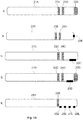
- FIG. 1B schematically illustrates various electrocatheter configurations A-E that may be used alternatively.
- Electrocatheter A comprises a body 21A, an electrode 22A and ring electrodes 23A and 24A.
- Electrode 22A may be used for measuring impedance and/or for ablation purposes.
- the ring electrodes may be used to detect voltage or to inject current.
- Electrocatheter B may comprise a body 21B, an electrode 22B and ring electrodes 23B and 24B.
- Electrode 22A may be smaller than the one used in electrocatheter A and may be used for measuring voltage or for injecting current.
- the ring electrodes may be used, as previously, to detect voltage or to inject current.
- Electrocatheter C may be similar to electrocatheter B.
- Electrocatheter D may comprise a body 21D, an electrode 22D at the tip of the body 21D, ring electrodes 23D and 24D and a lateral electrode 25D. Electrode 22D may be used for ablation whereas electrode 25D may be used for measuring voltage or for injecting current.
- the ring electrodes may be used, as previously, to detect voltage or to inject current.
- Electrocatheter E may comprise a body 21E, one or more ring electrodes 23E and an array of four lateral electrodes 25E, 26E, 27E and 28E.
- the lateral electrodes may be used for injection or voltage detection and measurement whereas the ring electrodes may be used, as previously, to detect voltage or to inject current, accordingly.
- the array of four lateral electrodes may comprise a mechanism to separate them from the catheter surface so that they may contact the myocardium tissue without the catheter body coming in contact with the tissue.
- the array of four electrodes may be arranged around the tip of the catheter.
- Another alternative is to use a catheter with many electrodes, for example over an almost cylindrical surface that may be inflated against the surface of a cardiac chamber and to take measurements between selectable electrodes.
- the fast broadband EIS methods injects bursts or a continuous periodic signal that contains a set of measurement frequencies simultaneously.
- the minimum length of this signal is one period of the slowest frequency. That is, in a typical case, 1 ms for a minimum frequency of 1 kHz. This would allow acquiring a maximum of 1000 whole impedance spectra per second. Nevertheless, this is usually not needed and a few tenths of spectra per second are enough.
- FIG. 2 describes this acquisition method.
- the voltage and current bursts are drawn longer that they can be for clarity. They can be as short as 1/1000 th of the approximate cycle period.
- FIG. 2 is a representation of the (non-)periodic broadband EIS for the nonparametric-in-time measurement of the time-varying bioimpedance Z( ⁇ k,t), with ⁇ k being the excitation (angular) frequency.
- Two possible approaches exist where the bio-system is excited either (A) with a continuous reference broadband signal r(t)or (B) with a non-continuous one. (see " Sanchez B et al. A new measuring and identification approach for time-varying bioimpedance using multisine electrical impedance spectroscopy. Physiol Meas. 2013;34:339-57 ").
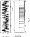
- FIG. 3 displays an example of multisine signal and its spectrum.
- the amplitudes and frequencies can be distributed to reach an optimal adaptation to the expected impedance spectrum and there are several methods to distribute the phase of the multisine components in order to reach a minimum amplitude, for a given RMS signal value given by the amount of frequency components and their corresponding amplitudes. This is usually referred as obtaining a minimal Crest Factor (the ratio between the peak amplitude and the RMS value. Crest factors in the range of 1.5 to 3 can be obtained for multisines with 20-25 components.
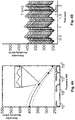
- FIG. 4A summarizes this by representing a resistivity spectrum which has a modulation due to myocardium movement, but being now this modulation a source of information, given that the waveform of the impedance as a function of time can be determined at every measured frequency (41 kHz for example in the figure).
- FIG. 4B represents the modulation of the resistivity waveform due to myocardium movement. It shows the time course of the impedance as a function of time, represented for all 26 measured frequencies. The mean value clearly changes, but also the signal shapes may change from low frequencies to high frequencies, and may change in a different way if there is a pathology.
- the acquired spectra can be fitted to one or several curves that follow the Cole model and then be parametrized by four parameters.
- the parameter R 0 provides information on the extracellular space while R ⁇ depends on the total volume and the ratio between them on the cell density.
- the central relaxation frequency f c depends on the average cell size and the parameter ⁇ is related to the cell shape and size homogeneity. That means that structural information about the tissue can be obtained from the spectra obtained at every cycle point. If represented in the Wessel plane, the impedance spectra of impedance relaxations of biological materials describe circumference arcs.
- FIG. 5 (Wessel plane) displays the set of arcs corresponding to several cardiac cycles.
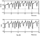
- FIG. 6A represents the time course of R 0 , R ⁇ , FIG. 6B the time course of ⁇ and FIG. 6C the time course of f c obtained by acquiring 60 spectra per second and fitting them to the Cole model for impedance.
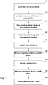
- FIG. 7 is a flow diagram of a method of assessing a cardiac tissue.
- a first block 705 an area of interest of the cardiac tissue is selected.
- one or more measurement locations in the selected area of interest are identified.
- an electrocatheter probe at the one or more measurement locations is placed.
- a broadband spectrum signal is provided to the one or more measurement locations using the electrocatheter probe.
- a diastolic phase of the cardiac cycle is identified.
- the impedance of the cardiac tissue is measured during the identified diastolic phase.
- a systolic phase of the cardiac cycle is identified.
- impedance of the cardiac tissue is measured during the identified systolic phase.
- the cardiac tissue is assessed and displayed based on the diastolic and systolic phase impedance measurements.
- FIG.7A displays impedance spectra of three tissue states and their modulation range due to myocardium movement in three tissue states, characterized by their fibrosis percentage: normal tissue (2% fibrosis), healed scar (84% fibrosis) and border zone (53% fibrosis).
- FIG. 7B shows the arcs in the Wessel plane for the three regions. It can be seen how normal tissue has higher impedance while healed scar has not only lower average impedance but also lower modulation and an almost flat spectrum, revealing its resistive behaviour due to the absence of viable cells. Border zone is similar to the non-transmural infarction areas that can be foci of arrhythmia.
- FIG. 8 shows the time-domain of impedance magnitude at a selected frequency (1 kHz) of 4 different tissues states. In this case, also an acute ischemic area is included. It can be seen how the different tissue-state areas provide not only different average impedance values, but also different modulations and different signal shapes
- FIG. 9 shows magnitude of the normal (NZ), border (BZ) and healed-scar (infarcted, IZ) zones impedance time signal at three different frequencies (1 kHz, 307 kHz and 939 kHz).
- FIG. 10 shows the corresponding phase angle at the same frequencies as the ones indicated in FIG. 9 . It can be seen how not only the average value, modulation and signal shape (slope, symmetry, number of local maxima and minima, complexity (spectral content), but also how these features change with frequency. Therefore it is possible to define estimators with more information content and more ability to separate measures using the combined time and frequency content.
- the variables involved in the definition of estimators of the tissue state can be not only impedance but also admittance or the related intrinsic parameters, resistivity, conductivity and permittivity.
- the estimators can take into account the values and the absolute or relative changes of the magnitude or phase angle or their alternative representations as real and imaginary part. It can also take into account the model parameters after fitting any of the aforementioned variables spectrum to a mathematical model. Their time course or their values in selected points of the cardiac cycle. In a preferred case, in the systolic and diastolic points determined by synchronism with other physiological signals (ECG, arterial or left ventricular pressure), or in the maximum and minimum of impedance or admittance related signals. Information can also be contained in the delay respect these signals.
- FIG.11 represents the resistivity time course at a frequency of 1 kHz, for two tissue state (normal and acute ischemic) together with the synchronously acquired ventricle pressure, its derivative and the ECG.
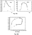
- FIG. 12A represents the resistivity at a given frequency (top) and the left ventricular pressure (LVP) (bottom).
- FIG. 12B the cycle described by the evolution of the signal in the Resistivity-LVP plane is shown.
- the pressure-Volume diagram whose area represents the work performed by the whole ventricle.
- the pressure the pressure
- the impedance in a localized point Being the impedance dependent on the myocardium movement in that point, the area of the figure would depend on the work performed by that part of the myocardium. Then it would allow distinguishing active regions (those where the cells contraction provokes the pressure change and where the cells contraction precedes the pressure rise from passive zones, those where tissue deformation is consequence of the pressure change and where both changes are in-phase.
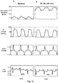
- FIGS 13A and 13B respectively show the Resistivity-LVP loop at baseline and after 30 min. of left anterior descending (LAD) coronary artery occlusion, and the Resistivity-LVP loop area mean at different frequencies at baseline and after 30 minutes of ischemia.
- the figures show how the area of the Resistivity-LVP loop is reduced after 30 minutes of acute ischemia compared to its baseline value.
- Both tissues have mobility, but the ischemic one is following passively the movement induced by the pressure, showing the impedance less delay respect to the pressure and being the Resistivity -LVP diagram near to a line, then having less area.
- FIG. 13B shows how the separation between both tissue states is better at a given frequency, then having again the time-frequency impedance acquisition an added value.
- FIG. 14 shows the Resistivity-LVP loop for four different tissue-states.
- the healed scar not only has lower resistivity but also shows almost no area because it follows the movement passively, then in-phase with the LV pressure.
- the border-zone our detection target, has a smaller impedance and impedance modulation that the normal (basal) tissue, but, still having active myocytes, it performs work and shows higher area value.
- Myocardial healthy tissue, non-transmural infarct zones and transmural infarct zones can be recognized in vivo by specific changes of their myocardial electrical impedance.
- Myocardial impedance mapping can identify the degree of fibrosis, and therefore the extent and transmurality of the infarct scar. This technique may improve the yielding of catheter ablation of ventricular arrhythmias in patients with chronic myocardial infarction.
- FIG. 15 illustrates a schematic representation of a heart with two electrocatheters; one in the left ventricle 135 and one in the right ventricle 140.
- the grey area in between the catheters 145 represents an infarct scar in the mid-cardiac septum that could not be detected using the measure of voltage but that can be detected by the impedance spectroscopy measurements.
- FIG. 16A illustrates the mean value of resistivity (top) and phase angle (bottom) vs. the excitation frequency for three different tissues: healthy tissue (N), non-transmural and transmural infarcted scar (IS N and IS T , respectively).
- the mean impedance values during the cardiac cycle of the normal myocardium declines significantly at increasing current frequencies (N: 285.5 ⁇ 10.4 vs. IS N : 216.4 ⁇ 7.3 vs. IS T : 155.5 ⁇ 6 ⁇ cm, at 41 kHz; p ⁇ 0.001) and the phase angle shows a negative relaxation that reaches a maximum at about 307 kHz (N: -5.6 ⁇ 0.4 vs. IS N : -4 ⁇ 0.4 vs. IS T : -1.7 ⁇ 0.2°, at 41 kHz; p ⁇ 0.001).
- the infarct scar shows lower resistivity values and less marked phase angle deviation at all frequencies.
- the curves of frequency dependence of resistivity and phase angle depict a progressive attenuation towards the sites as the recording site moves to areas with transmural necrosis.
- the current frequencies that better differentiate the transmural and non-transmural scar are 1 kHz, 41 kHz and 307 kHz for resistivity and 41 kHz, 307 kHz and 1 MHz for the phase angle.
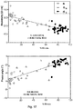
- FIG. 17 illustrates a linear correlation between myocardial resistivity (upper-left) / phase angle (lower-left) and the percentage of fibrosis.
- White filled circles correspond to samples with ⁇ 10% fibrosis, gray triangles to samples with 10% to 70% of fibrosis and black squares to samples with fibrosis higher than 70%.
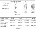
- the best correlation coefficient is obtained at 1 kHz for myocardial resistivity and 41 kHz for phase angle (Table 1).
- FIG. 18 illustrates the comparative pattern of the Cole impedance model obtained in normal (N: white), non-transmural scar (IS N : grey) and infarcted transmural scar (IS T : black).
- the Cole arc showed two main changes: a progressive decrease of the area under the curve and a left and down shift towards lower resistivity values (real and imaginary components, respectively).
- Table 2 summarizes the mean values of the Cole parameters (R 0 , R inf , ⁇ and f c ) in 59 tissue samples obtained from the 3 index myocardial regions.
- myocardial tissue electrical resistivity in the normal myocardium depicts a phasic pattern during the cardiac cycle: a peak shortly after the R wave and a minimum value appear in the region of the T wave.
- the non-transmural infarcted region depicts a pattern similar to normal myocardium.
- the transmural necrotic region shows a marked attenuation of the magnitude of the resistivity changes with a delayed occurrence of the maximal and minimal resistivity values.
- ROC receiver operating characteristic
- Table 3 shows the accuracy of the ROC curve assessed by the area under the ROC curve (AUC) for all the different studied variables with its statistical significance levels.
- Resistivity, phase angle, resistivity amplitude, delay t 1 , R 0 , R inf , and f c exhibit good values of AUC with significant p-values, being f c the best parameter.
- FIG. 20 which is a multiparametric analysis showing that a combination of resistivity and f c improve the predictive ability to discriminate between both fibrotic tissues.
Landscapes
- Health & Medical Sciences (AREA)
- Life Sciences & Earth Sciences (AREA)
- Cardiology (AREA)
- Heart & Thoracic Surgery (AREA)
- Molecular Biology (AREA)
- Veterinary Medicine (AREA)
- Biophysics (AREA)
- Pathology (AREA)
- Engineering & Computer Science (AREA)
- Biomedical Technology (AREA)
- Public Health (AREA)
- Medical Informatics (AREA)
- Physics & Mathematics (AREA)
- Surgery (AREA)
- Animal Behavior & Ethology (AREA)
- General Health & Medical Sciences (AREA)
- Physiology (AREA)
- Hematology (AREA)
- Vascular Medicine (AREA)
- Nuclear Medicine, Radiotherapy & Molecular Imaging (AREA)
- Radiology & Medical Imaging (AREA)
- Measurement And Recording Of Electrical Phenomena And Electrical Characteristics Of The Living Body (AREA)
Claims (15)
- Eine Vorrichtung umfassend:ein Mittel zur Auswahl von einem Bereich von Interesse eines Herzgewebes;ein Mittel zur Identifizierung von Messstellen im ausgewählten Bereich von Interesse;ein Mittel zur Anordnung von einer Elektrokathetersonde an den Messstellen;ein Mittel zur Bereitstellung von einem breitbandigen Signal an die Messstellen durch den Einsatz der Elektrokathetersonde;ein Mittel zur Identifizierung von einer diastolischen Phase des Herzzyklus;ein Mittel zur Messung der Impedanz des Herzgewebes an den Messstellen während der identifizierten diastolischen Phase;ein Mittel zur Identifizierung von einer systolischen Phase des Herzzyklus;ein Mittel zur Messung der Impedanz des Herzgewebes an den Messstellen während der identifizieren systolischen Phase;ein Mittel zur Beurteilung des Herzgewebes beruhend auf den diastolischen und systolischen Impedanzmessungen an den Messstellen, wobei das Mittel zur Beurteilung des Herzgewebes Mittel umfasst zum:
Identifizieren von eines spezifischen Widerstands und eines Phasenwinkels der Impedanzmessungen an den Messstellen, und wobei das Mittel zur Beurteilung des Herzgewebes weiterhin dadurch gekennzeichnet ist, dass es Mittel umfasst zum:Feststellen von einem Fibrosengrad an den Messstellen beruhend auf einer negativen Korrelation zwischen dem spezifischen Widerstand und dem Fibrosengrad und auf einer positiven Korrelation zwischen dem Phasenwinkel und dem Fibrosengrad, undIdentifizieren von einem Infarktnarbenumfang und Transmuralität in Abhängigkeit von dem festgestellten Fibrosengrad an den Messstellen. - Vorrichtung nach Anspruch 1, wobei das Mittel zur Anordnung von einer Elektrodensonde auf den Messstellen ein Mittel zur Auswahl von einer zeitlichen Reihenfolge von Messungen auf den Messstellen, ein Mittel zur sukzessiven Anordnung der Impedanzmesssonde an jeder Messstelle umfasst.
- Vorrichtung nach Anspruch 1 oder 2, wobei die identifizierte systolische Phase eine Präejektionsphase und eine Ejektionsphase umfasst und das Mittel zur Messung der Impedanz während der systolischen Phase ein Mittel zur Messung der Impedanz während der Präejektionsphase und ein Mittel zur Messung der Impedanz während der Ejektionsphase umfasst.
- Vorrichtung nach Anspruch 3, wobei das Mittel zur Messung der Impedanz zwei Elektrokatheter umfasst, wobei der eine zur Anordnung an einer Stelle des Herzgewebes und der andere zur Anordnung an einer anderen Stelle des Herzgewebes oder des Körpers konfiguriert ist.
- Vorrichtung nach Anspruch 4, wobei das Mittel zur Messung der Impedanz einen Elektrokatheter umfasst, der zur Anordnung an einer Stelle des Herzgewebes konfiguriert ist, und eine ausgewählte Elektrode umfasst, die an einer anderen Stelle des Körpers angeordnet ist.
- Vorrichtung nach einem der Ansprüche 1 bis 5, wobei das breitbandige Signal vielfache Stromimpulse mit Frequenzen von zwischen 1 kHz und 1 MHz umfasst.
- Vorrichtung nach einem der Ansprüche 1 bis 6, wobei das Mittel zur Messung der Impedanz ein Mittel zur in-vivo-Messung der Impedanz ist.
- Vorrichtung nach Anspruch 7 weiterhin umfassend ein Mittel zur Ablation des fibrotischen Bereichs.
- Vorrichtung nach einem der Ansprüche 1 bis 8, weiterhin umfassend ein Mittel zur Aufnahme von einer Anzahl an Spektren über den Herzzyklus, welche die Rekonstruktion von Zeitsignalen bei verschiedenen und gleichzeitigen Frequenzen ermöglichen und Indikatoren der Signalenform nutzen, um das Herzgewebe zu beurteilen.
- Vorrichtung nach Anspruch 9, wobei die Indikatoren der Signalenform einen oder mehrere von den folgenden umfassen: (i) eine Steigung der Signale für ausgewählte Punkte, (ii) die Anzahl und die Art der lokalen Maxima und Minima der Signale, und (iii) einen Spektralgehalt.
- Vorrichtung nach einem der Ansprüche 7 bis 10, wobei das Mittel zur Identifizierung der systolischen und diastolischen Phasen Synchronismus mit anderen physiologischen Signalen umfassend eines oder mehrere von den folgenden nutzen: (i) ein EKG-Signal, (ii) ein Drucksignal und (iii) ein Fluxsignal, (iv) ein Maximum und ein Minimum der auf die Impedanz oder auf die Admittanz bezogenen Signale, um die Phasen zu identifizieren.
- Vorrichtung nach einem der Ansprüche 7 bis 11, wobei das Mittel zur Messung der Impedanz ein Mittel zur Messung von einer oder mehreren der Eigenvariablen der Impedanz umfasst.
- Vorrichtung nach Anspruch 12, wobei das Mittel zur Messung der Impedanz die Werte und die absoluten oder die relativen Änderungen der Größe oder des Phasenwinkels oder der alternativen Darstellungen als Real- und Imaginärteil, und/oder die Modellparameter, nachdem eine von den genannten Variablenspektren an ein mathematisches Modell angepasst worden ist, deren Zeitverlauf oder deren Werte für ausgewählte Punkte des Herzzyklus berücksichtigt.
- Vorrichtung nach einem der Ansprüche 11 bis 13, wobei das Mittel zur Beurteilung des Herzgewebes konfiguriert ist, um eine Beurteilung aus auf die Pathologie bezogenen Verzögerungen zwischen den Bezugssignalen (arteriellem oder linksventrikulärem Druck, EKG) und auf die Impedanz bezogenen Signalen herzuleiten.
- Vorrichtung nach einem der Ansprüche 11 bis 13, wobei das Mittel zur Beurteilung des Herzgewebes konfiguriert ist, um eine Beurteilung aus der auf die Pathologie bezogenen Form und/oder Fläche der durch die Darstellung von einer auf die Impedanz bezogenen Variable bei einer oder mehreren Frequenzen und des Ventrikeldrucks erhaltenen Figur herzuleiten.
Applications Claiming Priority (1)
| Application Number | Priority Date | Filing Date | Title |
|---|---|---|---|
| PCT/EP2016/056933 WO2017167360A1 (en) | 2016-03-30 | 2016-03-30 | Systems and methods to assess infarcted myocardial tissue by measuring electrical impedance during the cardiac cycle |
Publications (2)
| Publication Number | Publication Date |
|---|---|
| EP3435858A1 EP3435858A1 (de) | 2019-02-06 |
| EP3435858B1 true EP3435858B1 (de) | 2020-07-08 |
Family
ID=55640745
Family Applications (1)
| Application Number | Title | Priority Date | Filing Date |
|---|---|---|---|
| EP16712341.3A Active EP3435858B1 (de) | 2016-03-30 | 2016-03-30 | Geräte zur beurteilung von myokardinfarktgewebe durch messung der elektrischen impedanz während des herzzyklus |
Country Status (3)
| Country | Link |
|---|---|
| US (1) | US20190110710A1 (de) |
| EP (1) | EP3435858B1 (de) |
| WO (1) | WO2017167360A1 (de) |
Cited By (2)
| Publication number | Priority date | Publication date | Assignee | Title |
|---|---|---|---|---|
| WO2022084923A1 (en) * | 2020-10-21 | 2022-04-28 | University Of Southern California | Noninvasive cardiovascular event detection |
| WO2024033018A1 (en) | 2022-08-09 | 2024-02-15 | Biotronik Se & Co. Kg | System and method for characterization of an organic medium surrounding an electrode |
Families Citing this family (6)
| Publication number | Priority date | Publication date | Assignee | Title |
|---|---|---|---|---|
| US20220184345A1 (en) * | 2017-01-12 | 2022-06-16 | Rithim Biologics, Inc. | Targeted cardiac therapy |
| CN112334064A (zh) * | 2018-05-06 | 2021-02-05 | 纳维斯国际有限公司 | 测量电阻抗、接触力和组织性质 |
| RU2691009C1 (ru) * | 2018-05-14 | 2019-06-07 | Федеральное государственное бюджетное образовательное учреждение высшего образования "Национальный исследовательский Мордовский государственный университет им. Н.П. Огарёва" | Способ прогнозирования риска развития артериальной гипертензии и стрессиндуцированной кардиомиопатии на ранних стадиях у детей-спортсменов |
| DE102019209333A1 (de) * | 2019-06-27 | 2020-12-31 | B. Braun Melsungen Aktiengesellschaft | Verfahren zur Ermittlung eines lokalen Gewebetyps eines Körpergewebes und medizinisches System zur Ausführung eines solchen Verfahrens |
| CN115068106B (zh) * | 2022-05-25 | 2024-06-07 | 绍兴梅奥心磁医疗科技有限公司 | 导管压力矢量测量方法及装置 |
| WO2024013601A1 (en) * | 2022-07-12 | 2024-01-18 | Medtronic, Inc. | Timing of pulsed field ablation energy deliveries |
Family Cites Families (7)
| Publication number | Priority date | Publication date | Assignee | Title |
|---|---|---|---|---|
| US20040260278A1 (en) * | 1996-10-22 | 2004-12-23 | Anderson Scott C. | Apparatus and method for ablating tissue |
| US20070191901A1 (en) * | 2004-06-04 | 2007-08-16 | Pacesetter, Inc. | Quantifying systolic and diastolic cardiac performance from dynamic impedance waveforms |
| US7447543B2 (en) * | 2005-02-15 | 2008-11-04 | Regents Of The University Of Minnesota | Pathology assessment with impedance measurements using convergent bioelectric lead fields |
| WO2008105691A1 (en) * | 2007-02-28 | 2008-09-04 | St. Jude Medical Ab | Device and method for detecting a myocardial infarction and treating the myocardial infarction using therapeutic light |
| US9050016B2 (en) * | 2009-02-10 | 2015-06-09 | Siemens Medical Solutions Usa, Inc. | System for heart performance characterization and abnormality detection |
| US20110144510A1 (en) * | 2009-12-16 | 2011-06-16 | Pacesetter, Inc. | Methods to identify damaged or scarred tissue based on position information and physiological information |
| WO2014008489A1 (en) * | 2012-07-04 | 2014-01-09 | Cibiem, Inc. | Devices and systems for carotid body ablation |
-
2016
- 2016-03-30 EP EP16712341.3A patent/EP3435858B1/de active Active
- 2016-03-30 US US16/090,203 patent/US20190110710A1/en not_active Abandoned
- 2016-03-30 WO PCT/EP2016/056933 patent/WO2017167360A1/en not_active Ceased
Non-Patent Citations (1)
| Title |
|---|
| None * |
Cited By (4)
| Publication number | Priority date | Publication date | Assignee | Title |
|---|---|---|---|---|
| WO2022084923A1 (en) * | 2020-10-21 | 2022-04-28 | University Of Southern California | Noninvasive cardiovascular event detection |
| WO2022084925A1 (en) * | 2020-10-21 | 2022-04-28 | University Of Southern California | Noninvasive infarct size determination |
| US20230404488A1 (en) * | 2020-10-21 | 2023-12-21 | University Of Southern California | Noninvasive cardiovascular event detection |
| WO2024033018A1 (en) | 2022-08-09 | 2024-02-15 | Biotronik Se & Co. Kg | System and method for characterization of an organic medium surrounding an electrode |
Also Published As
| Publication number | Publication date |
|---|---|
| EP3435858A1 (de) | 2019-02-06 |
| US20190110710A1 (en) | 2019-04-18 |
| WO2017167360A1 (en) | 2017-10-05 |
Similar Documents
| Publication | Publication Date | Title |
|---|---|---|
| EP3435858B1 (de) | Geräte zur beurteilung von myokardinfarktgewebe durch messung der elektrischen impedanz während des herzzyklus | |
| Gunawardene et al. | A novel assessment of local impedance during catheter ablation: initial experience in humans comparing local and generator measurements | |
| US8160690B2 (en) | System and method for determining electrode-tissue contact based on amplitude modulation of sensed signal | |
| US8449535B2 (en) | System and method for assessing coupling between an electrode and tissue | |
| US9144382B2 (en) | Non-invasive methods and systems for producing cardiac electrogram characteristic maps for use with catheter ablation of ventricular tachycardia | |
| US20200163646A1 (en) | Systems and methods for mechanical mapping of cardiac rhythm | |
| US20170007157A1 (en) | Electrical-signal-based electrode-tissue contact detection | |
| US20080312521A1 (en) | System and method for determining electrode-tissue contact using phase difference | |
| Kühne et al. | Validation of a novel spiral mapping catheter for real-time recordings from the pulmonary veins during cryoballoon ablation of atrial fibrillation | |
| US11464437B2 (en) | Mid-field signal extraction | |
| Koutalas et al. | Contemporary mapping techniques of complex cardiac arrhythmias–identifying and modifying the arrhythmogenic substrate | |
| JP2017508528A (ja) | 電気生理学システム | |
| WO2008157399A1 (en) | System and method for determining electrode-tissue contact | |
| CN120548146A (zh) | 来自pfa施加的预测建模和病灶分区及指数/分数 | |
| EP4475779A1 (de) | Egm-frequenzanalyse zur läsionsbeurteilung | |
| CN119950009B (zh) | 一种脉冲电场心脏消融深度评估装置及方法、设备、介质 | |
| JP7830098B2 (ja) | 解剖学的構造マッピングデータの信号及び補正処理 | |
| US20240350770A1 (en) | Managing medical device equipment by online magnetic calibration of a catheter | |
| US20260083382A1 (en) | Creating Multiple Layers Of Electro-Anatomical Mappings of Cardiac Tissue at Different Depths Using Multi-Polar Signals | |
| EP4714354A1 (de) | Verbesserte charakterisierung von narbengewebe in verschiedenen tiefen auf basis von signalen aus verschiedenen elektroden | |
| Patel | Detection of the origin of congenital heart disease-induced arrhythmias with electrophysiology mapping | |
| US20220193422A1 (en) | Automatic post pacing interval measurement and display | |
| Bogun et al. | Ablation of Ventricular Tachycardia in Nonischemic Cardiomyopathy | |
| JP2026057561A (ja) | 多電極カテーテルの異なる側の電極の加重分析 | |
| WO2026011179A1 (en) | Systems, devices, components and methods for near-field differential complex impedance measurements in intracardiac pulsed field ablation catheters |
Legal Events
| Date | Code | Title | Description |
|---|---|---|---|
| STAA | Information on the status of an ep patent application or granted ep patent |
Free format text: STATUS: THE INTERNATIONAL PUBLICATION HAS BEEN MADE |
|
| PUAI | Public reference made under article 153(3) epc to a published international application that has entered the european phase |
Free format text: ORIGINAL CODE: 0009012 |
|
| STAA | Information on the status of an ep patent application or granted ep patent |
Free format text: STATUS: REQUEST FOR EXAMINATION WAS MADE |
|
| 17P | Request for examination filed |
Effective date: 20181030 |
|
| AK | Designated contracting states |
Kind code of ref document: A1 Designated state(s): AL AT BE BG CH CY CZ DE DK EE ES FI FR GB GR HR HU IE IS IT LI LT LU LV MC MK MT NL NO PL PT RO RS SE SI SK SM TR |
|
| AX | Request for extension of the european patent |
Extension state: BA ME |
|
| RIN1 | Information on inventor provided before grant (corrected) |
Inventor name: AMOROS FIGUERAS, GERARD Inventor name: GARCIA SANCHEZ, TOMAS Inventor name: CINCA CUSCULLOLA, JUAN Inventor name: BRAGOS BARDIA, RAMON Inventor name: ROSELL FERRER, FRANCESC XAVIER Inventor name: JORGE VIZUETE, ESTHER Inventor name: SANCHEZ TERRONES, BENJAMIN |
|
| DAV | Request for validation of the european patent (deleted) | ||
| DAX | Request for extension of the european patent (deleted) | ||
| GRAP | Despatch of communication of intention to grant a patent |
Free format text: ORIGINAL CODE: EPIDOSNIGR1 |
|
| STAA | Information on the status of an ep patent application or granted ep patent |
Free format text: STATUS: GRANT OF PATENT IS INTENDED |
|
| INTG | Intention to grant announced |
Effective date: 20200228 |
|
| GRAS | Grant fee paid |
Free format text: ORIGINAL CODE: EPIDOSNIGR3 |
|
| GRAA | (expected) grant |
Free format text: ORIGINAL CODE: 0009210 |
|
| STAA | Information on the status of an ep patent application or granted ep patent |
Free format text: STATUS: THE PATENT HAS BEEN GRANTED |
|
| AK | Designated contracting states |
Kind code of ref document: B1 Designated state(s): AL AT BE BG CH CY CZ DE DK EE ES FI FR GB GR HR HU IE IS IT LI LT LU LV MC MK MT NL NO PL PT RO RS SE SI SK SM TR |
|
| REG | Reference to a national code |
Ref country code: CH Ref legal event code: EP Ref country code: AT Ref legal event code: REF Ref document number: 1287575 Country of ref document: AT Kind code of ref document: T Effective date: 20200715 |
|
| REG | Reference to a national code |
Ref country code: DE Ref legal event code: R096 Ref document number: 602016039467 Country of ref document: DE |
|
| REG | Reference to a national code |
Ref country code: IE Ref legal event code: FG4D |
|
| REG | Reference to a national code |
Ref country code: NL Ref legal event code: FP |
|
| REG | Reference to a national code |
Ref country code: LT Ref legal event code: MG4D |
|
| REG | Reference to a national code |
Ref country code: AT Ref legal event code: MK05 Ref document number: 1287575 Country of ref document: AT Kind code of ref document: T Effective date: 20200708 |
|
| PG25 | Lapsed in a contracting state [announced via postgrant information from national office to epo] |
Ref country code: FI Free format text: LAPSE BECAUSE OF FAILURE TO SUBMIT A TRANSLATION OF THE DESCRIPTION OR TO PAY THE FEE WITHIN THE PRESCRIBED TIME-LIMIT Effective date: 20200708 Ref country code: LT Free format text: LAPSE BECAUSE OF FAILURE TO SUBMIT A TRANSLATION OF THE DESCRIPTION OR TO PAY THE FEE WITHIN THE PRESCRIBED TIME-LIMIT Effective date: 20200708 Ref country code: HR Free format text: LAPSE BECAUSE OF FAILURE TO SUBMIT A TRANSLATION OF THE DESCRIPTION OR TO PAY THE FEE WITHIN THE PRESCRIBED TIME-LIMIT Effective date: 20200708 Ref country code: NO Free format text: LAPSE BECAUSE OF FAILURE TO SUBMIT A TRANSLATION OF THE DESCRIPTION OR TO PAY THE FEE WITHIN THE PRESCRIBED TIME-LIMIT Effective date: 20201008 Ref country code: GR Free format text: LAPSE BECAUSE OF FAILURE TO SUBMIT A TRANSLATION OF THE DESCRIPTION OR TO PAY THE FEE WITHIN THE PRESCRIBED TIME-LIMIT Effective date: 20201009 Ref country code: ES Free format text: LAPSE BECAUSE OF FAILURE TO SUBMIT A TRANSLATION OF THE DESCRIPTION OR TO PAY THE FEE WITHIN THE PRESCRIBED TIME-LIMIT Effective date: 20200708 Ref country code: AT Free format text: LAPSE BECAUSE OF FAILURE TO SUBMIT A TRANSLATION OF THE DESCRIPTION OR TO PAY THE FEE WITHIN THE PRESCRIBED TIME-LIMIT Effective date: 20200708 Ref country code: PT Free format text: LAPSE BECAUSE OF FAILURE TO SUBMIT A TRANSLATION OF THE DESCRIPTION OR TO PAY THE FEE WITHIN THE PRESCRIBED TIME-LIMIT Effective date: 20201109 Ref country code: SE Free format text: LAPSE BECAUSE OF FAILURE TO SUBMIT A TRANSLATION OF THE DESCRIPTION OR TO PAY THE FEE WITHIN THE PRESCRIBED TIME-LIMIT Effective date: 20200708 Ref country code: BG Free format text: LAPSE BECAUSE OF FAILURE TO SUBMIT A TRANSLATION OF THE DESCRIPTION OR TO PAY THE FEE WITHIN THE PRESCRIBED TIME-LIMIT Effective date: 20201008 |
|
| PG25 | Lapsed in a contracting state [announced via postgrant information from national office to epo] |
Ref country code: RS Free format text: LAPSE BECAUSE OF FAILURE TO SUBMIT A TRANSLATION OF THE DESCRIPTION OR TO PAY THE FEE WITHIN THE PRESCRIBED TIME-LIMIT Effective date: 20200708 Ref country code: LV Free format text: LAPSE BECAUSE OF FAILURE TO SUBMIT A TRANSLATION OF THE DESCRIPTION OR TO PAY THE FEE WITHIN THE PRESCRIBED TIME-LIMIT Effective date: 20200708 Ref country code: PL Free format text: LAPSE BECAUSE OF FAILURE TO SUBMIT A TRANSLATION OF THE DESCRIPTION OR TO PAY THE FEE WITHIN THE PRESCRIBED TIME-LIMIT Effective date: 20200708 Ref country code: IS Free format text: LAPSE BECAUSE OF FAILURE TO SUBMIT A TRANSLATION OF THE DESCRIPTION OR TO PAY THE FEE WITHIN THE PRESCRIBED TIME-LIMIT Effective date: 20201108 |
|
| REG | Reference to a national code |
Ref country code: DE Ref legal event code: R097 Ref document number: 602016039467 Country of ref document: DE |
|
| PG25 | Lapsed in a contracting state [announced via postgrant information from national office to epo] |
Ref country code: IT Free format text: LAPSE BECAUSE OF FAILURE TO SUBMIT A TRANSLATION OF THE DESCRIPTION OR TO PAY THE FEE WITHIN THE PRESCRIBED TIME-LIMIT Effective date: 20200708 Ref country code: EE Free format text: LAPSE BECAUSE OF FAILURE TO SUBMIT A TRANSLATION OF THE DESCRIPTION OR TO PAY THE FEE WITHIN THE PRESCRIBED TIME-LIMIT Effective date: 20200708 Ref country code: RO Free format text: LAPSE BECAUSE OF FAILURE TO SUBMIT A TRANSLATION OF THE DESCRIPTION OR TO PAY THE FEE WITHIN THE PRESCRIBED TIME-LIMIT Effective date: 20200708 Ref country code: SM Free format text: LAPSE BECAUSE OF FAILURE TO SUBMIT A TRANSLATION OF THE DESCRIPTION OR TO PAY THE FEE WITHIN THE PRESCRIBED TIME-LIMIT Effective date: 20200708 Ref country code: DK Free format text: LAPSE BECAUSE OF FAILURE TO SUBMIT A TRANSLATION OF THE DESCRIPTION OR TO PAY THE FEE WITHIN THE PRESCRIBED TIME-LIMIT Effective date: 20200708 Ref country code: CZ Free format text: LAPSE BECAUSE OF FAILURE TO SUBMIT A TRANSLATION OF THE DESCRIPTION OR TO PAY THE FEE WITHIN THE PRESCRIBED TIME-LIMIT Effective date: 20200708 |
|
| PLBE | No opposition filed within time limit |
Free format text: ORIGINAL CODE: 0009261 |
|
| STAA | Information on the status of an ep patent application or granted ep patent |
Free format text: STATUS: NO OPPOSITION FILED WITHIN TIME LIMIT |
|
| PG25 | Lapsed in a contracting state [announced via postgrant information from national office to epo] |
Ref country code: AL Free format text: LAPSE BECAUSE OF FAILURE TO SUBMIT A TRANSLATION OF THE DESCRIPTION OR TO PAY THE FEE WITHIN THE PRESCRIBED TIME-LIMIT Effective date: 20200708 |
|
| 26N | No opposition filed |
Effective date: 20210409 |
|
| PG25 | Lapsed in a contracting state [announced via postgrant information from national office to epo] |
Ref country code: SK Free format text: LAPSE BECAUSE OF FAILURE TO SUBMIT A TRANSLATION OF THE DESCRIPTION OR TO PAY THE FEE WITHIN THE PRESCRIBED TIME-LIMIT Effective date: 20200708 |
|
| PG25 | Lapsed in a contracting state [announced via postgrant information from national office to epo] |
Ref country code: SI Free format text: LAPSE BECAUSE OF FAILURE TO SUBMIT A TRANSLATION OF THE DESCRIPTION OR TO PAY THE FEE WITHIN THE PRESCRIBED TIME-LIMIT Effective date: 20200708 |
|
| PG25 | Lapsed in a contracting state [announced via postgrant information from national office to epo] |
Ref country code: MC Free format text: LAPSE BECAUSE OF FAILURE TO SUBMIT A TRANSLATION OF THE DESCRIPTION OR TO PAY THE FEE WITHIN THE PRESCRIBED TIME-LIMIT Effective date: 20200708 |
|
| REG | Reference to a national code |
Ref country code: CH Ref legal event code: PL |
|
| REG | Reference to a national code |
Ref country code: BE Ref legal event code: MM Effective date: 20210331 |
|
| PG25 | Lapsed in a contracting state [announced via postgrant information from national office to epo] |
Ref country code: CH Free format text: LAPSE BECAUSE OF NON-PAYMENT OF DUE FEES Effective date: 20210331 Ref country code: LI Free format text: LAPSE BECAUSE OF NON-PAYMENT OF DUE FEES Effective date: 20210331 Ref country code: LU Free format text: LAPSE BECAUSE OF NON-PAYMENT OF DUE FEES Effective date: 20210330 Ref country code: IE Free format text: LAPSE BECAUSE OF NON-PAYMENT OF DUE FEES Effective date: 20210330 |
|
| PG25 | Lapsed in a contracting state [announced via postgrant information from national office to epo] |
Ref country code: BE Free format text: LAPSE BECAUSE OF NON-PAYMENT OF DUE FEES Effective date: 20210331 |
|
| PG25 | Lapsed in a contracting state [announced via postgrant information from national office to epo] |
Ref country code: CY Free format text: LAPSE BECAUSE OF FAILURE TO SUBMIT A TRANSLATION OF THE DESCRIPTION OR TO PAY THE FEE WITHIN THE PRESCRIBED TIME-LIMIT Effective date: 20200708 |
|
| PG25 | Lapsed in a contracting state [announced via postgrant information from national office to epo] |
Ref country code: HU Free format text: LAPSE BECAUSE OF FAILURE TO SUBMIT A TRANSLATION OF THE DESCRIPTION OR TO PAY THE FEE WITHIN THE PRESCRIBED TIME-LIMIT; INVALID AB INITIO Effective date: 20160330 |
|
| PG25 | Lapsed in a contracting state [announced via postgrant information from national office to epo] |
Ref country code: MK Free format text: LAPSE BECAUSE OF FAILURE TO SUBMIT A TRANSLATION OF THE DESCRIPTION OR TO PAY THE FEE WITHIN THE PRESCRIBED TIME-LIMIT Effective date: 20200708 |
|
| PG25 | Lapsed in a contracting state [announced via postgrant information from national office to epo] |
Ref country code: TR Free format text: LAPSE BECAUSE OF FAILURE TO SUBMIT A TRANSLATION OF THE DESCRIPTION OR TO PAY THE FEE WITHIN THE PRESCRIBED TIME-LIMIT Effective date: 20200708 |
|
| PG25 | Lapsed in a contracting state [announced via postgrant information from national office to epo] |
Ref country code: MT Free format text: LAPSE BECAUSE OF FAILURE TO SUBMIT A TRANSLATION OF THE DESCRIPTION OR TO PAY THE FEE WITHIN THE PRESCRIBED TIME-LIMIT Effective date: 20200708 |
|
| PGFP | Annual fee paid to national office [announced via postgrant information from national office to epo] |
Ref country code: DE Payment date: 20250327 Year of fee payment: 10 |
|
| PGFP | Annual fee paid to national office [announced via postgrant information from national office to epo] |
Ref country code: NL Payment date: 20250327 Year of fee payment: 10 |
|
| PGFP | Annual fee paid to national office [announced via postgrant information from national office to epo] |
Ref country code: GB Payment date: 20250327 Year of fee payment: 10 |
|
| PGFP | Annual fee paid to national office [announced via postgrant information from national office to epo] |
Ref country code: FR Payment date: 20260325 Year of fee payment: 11 |