EP3435487A1 - Dispositif porte-repere pour bloc de jonction - Google Patents
Dispositif porte-repere pour bloc de jonction Download PDFInfo
- Publication number
- EP3435487A1 EP3435487A1 EP17183204.1A EP17183204A EP3435487A1 EP 3435487 A1 EP3435487 A1 EP 3435487A1 EP 17183204 A EP17183204 A EP 17183204A EP 3435487 A1 EP3435487 A1 EP 3435487A1
- Authority
- EP
- European Patent Office
- Prior art keywords
- marker
- terminal block
- bearing
- extension
- fastener
- Prior art date
- Legal status (The legal status is an assumption and is not a legal conclusion. Google has not performed a legal analysis and makes no representation as to the accuracy of the status listed.)
- Granted
Links
Images
Classifications
-
- H—ELECTRICITY
- H01—ELECTRIC ELEMENTS
- H01R—ELECTRICALLY-CONDUCTIVE CONNECTIONS; STRUCTURAL ASSOCIATIONS OF A PLURALITY OF MUTUALLY-INSULATED ELECTRICAL CONNECTING ELEMENTS; COUPLING DEVICES; CURRENT COLLECTORS
- H01R9/00—Structural associations of a plurality of mutually-insulated electrical connecting elements, e.g. terminal strips or terminal blocks; Terminals or binding posts mounted upon a base or in a case; Bases therefor
- H01R9/22—Bases, e.g. strip, block, panel
- H01R9/24—Terminal blocks
- H01R9/26—Clip-on terminal blocks for side-by-side rail- or strip-mounting
- H01R9/2683—Marking plates or tabs
-
- G—PHYSICS
- G09—EDUCATION; CRYPTOGRAPHY; DISPLAY; ADVERTISING; SEALS
- G09F—DISPLAYING; ADVERTISING; SIGNS; LABELS OR NAME-PLATES; SEALS
- G09F3/00—Labels, tag tickets, or similar identification or indication means; Seals; Postage or like stamps
- G09F3/08—Fastening or securing by means not forming part of the material of the label itself
- G09F3/18—Casings, frames or enclosures for labels
- G09F3/20—Casings, frames or enclosures for labels for adjustable, removable, or interchangeable labels
- G09F3/205—Casings, frames or enclosures for labels for adjustable, removable, or interchangeable labels specially adapted for electric cables, pipes or the like
-
- H—ELECTRICITY
- H01—ELECTRIC ELEMENTS
- H01R—ELECTRICALLY-CONDUCTIVE CONNECTIONS; STRUCTURAL ASSOCIATIONS OF A PLURALITY OF MUTUALLY-INSULATED ELECTRICAL CONNECTING ELEMENTS; COUPLING DEVICES; CURRENT COLLECTORS
- H01R13/00—Details of coupling devices of the kinds covered by groups H01R12/70 or H01R24/00 - H01R33/00
- H01R13/46—Bases; Cases
- H01R13/465—Identification means, e.g. labels, tags, markings
Definitions
- the present invention relates to the field of connection devices and / or electrical connection, including terminal blocks; more particularly, the invention relates to a marker-bearing system for one or more terminal blocks, comprising one or more marker-bearing devices for as many terminal blocks and a fastening element disposed on the terminal block or blocks.
- the invention therefore aims to provide a simple solution to all or part of these problems.
- the present invention relates to an electrical terminal block marker carrier system
- a longitudinal marker carrier device in an extension direction, with a first end in the extension direction and a second end in the direction of extension. opposite to the extension direction, the system comprising a first attachment member configured to be disposed on the terminal block, the first end and / or the second end being configured to cooperate releasably with the first attachment member and a rotatable link between a first position in which a first face of the marker carrier is oriented towards the terminal block and a second face of the marker carrier is oriented in a direction opposite to the terminal block, and a second position in which the first face of the marker-holder device is oriented in an opposite direction at the terminal block and the second face of the marker-holder device is oriented towards the terminal block.
- an opening or connecting element of the terminal block is at least partially covered by the marker-bearing device in one of the two positions, while the opening or the connecting element of the block junction is discovered when the marker-bearing device is in the other position.
- the device makes it possible to ensure, together with the marking function, a function of protecting or closing certain openings formed in the terminal block and intended to receive particular elements of connection between terminal block or Cables.
- a second fastener is configured to be disposed on the terminal block, the first end being configured to cooperate the first fastener and the second end being configured to cooperate with the second fastener .
- the device can be fixed by its two ends, removably, in the first or second position. When both ends of the device are fixed, it is no longer rotatable.
- the first end and / or the second end comprises a cylindrical portion, and longitudinal along an axis transverse to the extension direction, inserted into force in the at least one fastening element and movable in rotation around the axis.
- the device is adapted to the existing fasteners on the terminal blocks in use.
- the first end and the second end are configured to cooperate with the fastener, and wherein the marker carrier device comprises a thinned portion located between the first end and the second end.
- the device is divisible in two parts, each part can then independently of the other be used as marker device according to the invention.
- the invention also relates to an arrangement of a plurality of marker-bearing systems according to one of the preceding claims for a plurality of terminal blocks, each marker-carrying system of the plurality of marker-bearing systems comprising a carrier device.
- the marker and the fastener (s) configured to be disposed on a corresponding terminal block of the plurality of terminal blocks, the marker-bearing devices of the plurality of marker-bearing system being aligned in a direction transverse to the direction of extension of one of the devices, each marker-holder device being integrally attached to the marker-holder devices on either side of the marker-holder device, and the fastener or fasteners disposed on the terminal block being aligned correspondingly to aligning the first end or the second end of the marker-holder devices.
- the invention relates to a marker carrier system for a terminal block, comprising a marker carrier device 1 for a terminal block 11 and a fastener element 12 disposed on the terminal block 11.
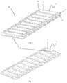
- the figure 1 is a perspective view of a linear array comprising ten edge-to-edge aligned marker-bearing devices 1 made in one piece in an electrically insulating material.
- Each marker-bearing device 1 is detachable from the linear arrangement 10, and can be used individually, independently of the other marker-bearing devices 1 of the arrangement 10.
- Each device is intended to be attached to an electrical terminal block 11.
- the figures 4 and 5 represent a set of ten terminal blocks 11, mounted side by side.
- Each terminal block 11 can be detached from the assembly and can be used individually, independently of the other terminal blocks of the assembly.
- Each terminal block comprises a portion of insulating material.
- each terminal block On the insulating material part of each terminal block is arranged at least one fastening element 12, as shown in FIG. figure 5 .
- the fastening element 12 is intended to receive in force a complementary element 3 located at one of the ends 2a, 2b of the marker-bearing device.
- the marker-bearing device 1 has a central portion of substantially parallelepipedal shape, elongated in an extension direction.
- Complementary element 3 is, in the embodiment described herein, an elongate cylinder in a direction transverse to the direction of extension of the marker-bearing device 1. The cylinder is held between two extensions of the central part of the carrier device. reference, located at one end 2a in the extension direction and / or at the other end 2b in the direction opposite to the direction of extension of the marker-bearing device.
- the central portion of the marker holder 1 has two opposite faces 5,6 on which can be reported a marker or a label with an appropriate reference.
- the marker-bearing device 1 When the cylindrical element 3, located at the end 2a or 2b of the marker-bearing device 1, is force-fitted into a fixing element 12 disposed on the terminal block 11, then the marker-bearing device 1 is attached, removably, at the terminal block 11, and it is rotatable about the axis of the cylindrical member 3, so that it can take a first position in which a first face 5 of the marker holder device 1 is oriented towards the terminal block 11 and a second face 6 of the marker-bearing device 1 is oriented in a direction opposite to the terminal block, or a second position in which the first face 5 of the marker-bearing device 1 is oriented in a direction opposite to the terminal block and the second face 6 of the marker-bearing device 1 is oriented towards the terminal block 11. It is thus possible to use a single device in a simple manner. to carry a different mark on the first face and on the second face. These two marks will be alternately visible in the first or in the second position.
- the latter can close, in one of its two positions, an opening 14 arranged in the connecting block 11, and when the opening 14 is to receive, according to its destination , a connecting element or a plug-in connector 13, the marker-bearing device 1 can open, as illustrated in FIG. figure 5 , to let the connecting element or the plug-in connector 13 pass, and then again to close to cover and protect this connecting element or this plug-in connector 13 after it has been inserted into the opening 14, as illustrated in FIG. figure 4 .
- the marker-holder device 1 illustrated on the figure 1 can be fixed by these two ends 2a and 2b simultaneously on the terminal block 11, provided that it is provided with two fasteners 12 corresponding to the cylindrical elements 3 at each end 2a and 2b. In this case, the marker-bearing device 1 is no longer rotatable.
- the latter comprises at its central portion a thinned portion 4, situated between the two ends 2a and 2b of the marker-bearing device 1, so that the marker-bearing device 1 is two-part breakable, each of which can become a marker-bearing device, but with a dimension in the direction of extension shorter than that of the initial marker holder device 1.
- Each marker device resulting from this two-part separation is then provided with a single end which can be attached to the terminal block in a rotary connection similar to that described above for the marker-bearing device 1 according to the first embodiment of FIG. production.
- the marker-holder devices can be used not only individually, but also grouped in linear arrangements which can accommodate an indeterminate number of marker-bearing devices 1, and intended to be mounted on as many corresponding terminal blocks gathered together.
- the invention thus also relates to an arrangement 10 of a plurality of marker bearing systems according to one of the variants described above, for a plurality of terminal blocks, each marker system of the plurality of marker-bearing systems.
- the marker-bearing devices 1 of the plurality of marker-bearing systems being aligned in a direction transverse to the direction of extension of one of the devices, each marker-bearing device 1 being integrally attached to the neighboring marker-holder devices 1 located on each side of this marker-holder device 1; the fastening element or elements 12 arranged on the terminal block being aligned correspondingly to the alignment of the ends 2a or the ends 2b of the marker-holder devices 1.
Landscapes
- Physics & Mathematics (AREA)
- General Physics & Mathematics (AREA)
- Engineering & Computer Science (AREA)
- Theoretical Computer Science (AREA)
- Connections Arranged To Contact A Plurality Of Conductors (AREA)
Description
- La présente invention se rapporte au domaine des dispositifs de raccordement et/ou de liaison électrique, notamment des blocs de jonction; plus particulièrement l'invention concerne un système porte-repère pour un ou plusieurs blocs de jonction, comprenant un ou plusieurs dispositifs porte-repère pour autant de bloc de jonction et un élément de fixation disposé sur le ou les blocs de jonction.
- Il est connu de clipser sur un bloc de jonction un dispositif destiné à réceptionner un repère qui porte une référence identique à la référence placée sur un repère lui-même clipsé sur un câble électrique raccordé à ce bloc de jonction. Ces dispositifs connus ne permettent néanmoins pas d'utiliser de manière simple un même dispositif pour repérer deux éléments distincts. Ils ne permettent pas non plus d'assurer, en même temps que la fonction de repérage, une fonction de protection ou de fermeture de certaines ouvertures formées dans le bloc de jonction et destinées à recevoir des éléments particuliers de liaison entre bloc de jonction ou des câbles. La configuration de ces dispositifs doit en outre pouvoir être facilement adaptée au besoin, en terme de dimension notamment, mais également en considérant les modes de fixation existants sur les blocs de jonction en service.
- L'invention a donc pour but de proposer une solution simple à tout ou partie de ces problèmes.
- A cet effet, la présente invention porte sur un système porte-repère pour bloc de jonction électrique comprenant un dispositif porte-repère longitudinal selon une direction d'extension, avec une première extrémité dans la direction d'extension et une deuxième extrémité dans la direction opposée à la direction d'extension, le système comprenant un premier élément de fixation configuré pour être disposé sur le bloc de jonction, la première extrémité et/ou la deuxième extrémité étant configurées pour coopérer avec le premier élément de fixation de manière amovible et selon une liaison rotative, entre une première position dans laquelle une première face du dispositif porte-repère est orientée vers le bloc de jonction et une deuxième face du dispositif porte-repère est orientée dans une direction opposée au bloc de jonction, et une deuxième position dans laquelle la première face du dispositif porte-repère est orientée dans une direction opposée au bloc de jonction et la deuxième face du dispositif porte-repère est orientée vers le bloc de jonction.
- Grâce à ces dispositions il est possible d'utiliser de manière simple un même dispositif pour porter un repère différent sur la première face et sur la deuxième face. Ces repères seront alternativement visibles dans la première ou dans la deuxième position.
- Selon un aspect de l'invention, une ouverture ou un élément de liaison du bloc de jonction est au moins en partie recouvert par le dispositif porte-repère dans une des deux positions, alors que l'ouverture ou l'élément de liaison du bloc de jonction est découvert lorsque le dispositif porte-repère est dans l'autre position.
- Grâce à ces dispositions le dispositif permet d'assurer, en même temps que la fonction de repérage, une fonction de protection ou de fermeture de certaines ouvertures formées dans le bloc de jonction et destinées à recevoir des éléments particuliers de liaison entre bloc de jonction ou des câbles.
- Selon un aspect de l'invention, un deuxième élément de fixation est configuré pour être disposé sur le bloc de jonction, la première extrémité étant configurée pour coopérer le premier élément de fixation et la deuxième extrémité étant configurée pour coopérer avec le deuxième élément de fixation.
- Grâce à ces dispositions, le dispositif peut être fixé par ses deux extrémités, de manière amovible, dans la première ou la deuxième position. Lorsque les deux extrémités du dispositif sont fixées, il n'est plus mobile en rotation.
- Selon un aspect de l'invention, la première extrémité et/ou la deuxième extrémité comprend une portion cylindrique, et longitudinale selon un axe transversal à la direction d'extension, insérée en force dans l'au moins un élément de fixation et mobile en rotation autour de l'axe.
- Grâce à ces dispositions, le dispositif est adapté aux éléments de fixation existants sur les blocs de jonction en service.
- Selon un aspect de l'invention, la première extrémité et la deuxième extrémité sont configurées pour coopérer avec l'élément de fixation, et dans lequel le dispositif porte-repère comprend une portion amincie située entre la première extrémité et la deuxième extrémité.
- Grâce à ces dispositions, le dispositif est sécable en deux parties, chaque partie pouvant alors indépendamment de l'autre être utilisée comme dispositif porte-repère selon l'invention.
- L'invention porte également sur un arrangement d'une pluralité de systèmes porte-repère selon l'une des revendications précédentes pour une pluralité de blocs de jonction, chaque système porte-repère de la pluralité de systèmes porte-repère comprenant un dispositif porte-repère et le ou les éléments de fixation configurés pour être disposés sur un bloc de jonction correspondant de la pluralité de blocs de jonction, les dispositifs porte-repère de la pluralité de système porte-repère étant alignés selon une direction transversale à la direction d'extension d'un des dispositifs, chaque dispositif porte-repère étant solidairement attaché aux dispositifs porte-repère situés de chaque côté de ce dispositif porte-repère, et le ou les éléments de fixation disposés sur le bloc de jonction étant alignés de manière correspondante à l'alignement des première extrémité ou des deuxième extrémité des dispositifs portes-repère.
- Pour sa bonne compréhension, l'invention est décrite en référence aux dessins ci-annexés représentant, à titre d'exemple non limitatif, une forme de réalisation d'un dispositif selon l'invention.
-
Figure 1 est une vue en perspective d'un arrangement linéaire de dispositifs porte-repère alignés. -
Figure 2 est une vue en perspective de l'arrangement de lafigure 1 , avec une vue sur la face opposée. -
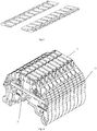
Figure 3 est une vue de l'arrangement présenté sur lesfigures 1 et 2 , après qu'il ait été séparé en deux parties. -
Figure 4 est une vue en perspective d'un bloc de jonction, équipé de plusieurs arrangements linéaires de dispositifs porte-repères, tous en position fermée. -
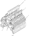
Figure 5 est une vue en perspective d'un bloc de jonction, équipé de plusieurs arrangements linéaires de dispositifs porte-repères, en position ouverte. - L'invention concerne un système porte-repère pour un bloc de jonction, comprenant un dispositif porte-repère 1 pour un bloc de jonction 11 et un élément de fixation 12 disposé sur le bloc de jonction 11.
- La
figure 1 est une vue en perspective d'un arrangement linéaire 10 comprenant dix dispositifs porte-repères 1 alignés bord-à-bord et fabriqué d'un seul tenant dans un matériau électriquement isolant. Chaque dispositif porte-repère 1 est détachable de l'arrangement linéaire 10, et est utilisable individuellement, indépendamment des autres dispositifs porte-repère 1 de l'arrangement 10. - Chaque dispositif est destiné à être fixé à un bloc de jonction électrique 11. Les
figures 4 et5 représentent un ensemble de dix blocs de jonction 11, montés côte-à-côte. Chaque bloc de jonction 11 peut être détaché de l'ensemble et est utilisable individuellement, indépendamment des autres blocs de jonction de l'ensemble. Chaque bloc de jonction comprend une partie en matériau isolant. - Sur la partie en matériau isolant de chaque bloc de jonction est disposé au moins un élément de fixation 12, tel que représenté sur la
figure 5 . L'élément de fixation 12 est destiné à recevoir en force un élément complémentaire 3 situé à l'une des extrémités 2a, 2b du dispositif porte-repère. Le dispositif porte-repère 1 a une partie centrale de forme sensiblement parallélépipédique, allongée selon une direction d'extension. L'élément complémentaire 3 est, dans le mode de réalisation décrit ici, un cylindre allongé dans une direction transversale à la direction d'extension du dispositif porte-repère 1. Le cylindre est maintenu entre deux extensions de la partie centrale du dispositif porte-repère, situées à une extrémité 2a dans la direction d'extension et/ou à l'autre extrémité 2b dans la direction opposée à la direction d'extension du dispositif porte-repère. - La partie centrale du porte-repère 1 a deux faces opposées 5,6 sur lesquelles peuvent être rapportés un repère ou une étiquette portant une référence appropriée.
- Lorsque l'élément cylindrique 3, situé à l'extrémité 2a ou 2b du dispositif porte-repère 1, est inséré en force dans un élément de fixation 12 disposé sur le bloc de jonction 11, alors le dispositif porte-repère 1 est attaché, de manière amovible, au bloc de jonction 11, et il est mobile en rotation autour de l'axe de l'élément cylindrique 3, de sorte qu'il peut prendre une première position dans laquelle une première face 5 du dispositif porte-repère 1 est orientée vers le bloc de jonction 11 et une deuxième face 6 du dispositif porte-repère 1 est orientée dans une direction opposée au bloc de jonction, ou une deuxième position dans laquelle la première face 5 du dispositif porte-repère 1 est orientée dans une direction opposée au bloc de jonction et la deuxième face 6 du dispositif porte-repère 1 est orientée vers le bloc de jonction 11. Il est ainsi possible d'utiliser de manière simple un même dispositif pour porter un repère différent sur la première face et sur la deuxième face. Ces deux repères seront alternativement visibles dans la première ou dans la deuxième position.
- Selon une deuxième utilisation du dispositif porte-repère 1, celui-ci peut fermer, dans l'une de ses deux positions, une ouverture 14 aménagée dans le bloc de liaison 11, et lorsque l'ouverture 14 doit recevoir, conformément à sa destination, un élément de liaison ou un connecteur débrochable 13, le dispositif porte-repère 1 peut s'ouvrir, comme cela est illustré en
figure 5 , pour laisser passer l'élément de liaison ou le connecteur débrochable 13, puis à nouveau se refermer pour couvrir et protéger cet élément de liaison ou ce connecteur débrochable 13 après son insertion dans l'ouverture 14, comme cela est illustré enfigure 4 . - Le dispositif porte-repère 1 illustré sur la
figure 1 peut être fixé par ces deux extrémités 2a et 2b simultanément sur le bloc de jonction 11, sous-réserve que celui-ci soit muni de deux éléments de fixation 12 correspondants aux éléments cylindriques 3 situés à chaque extrémité 2a et 2b. Dans ce cas, le dispositif porte-repère 1 n'est plus mobile en rotation. - Selon une variante du dispositif porte-repère 1, celui-ci comporte au niveau de sa partie centrale une portion amincie 4, située entre les deux extrémités 2a et 2b du dispositif porte-repère 1, de sorte que le dispositif porte-repère 1 est sécable en deux partie, qui chacune peut devenir un dispositif porte-repère, avec toutefois une dimension selon la direction d'extension plus courte que celle du dispositif porte-repère 1 initial. Chaque dispositif porte-repère issue de cette séparation en deux parties est alors muni d'une seule extrémité qui peut être fixée au bloc de jonction selon une liaison rotative similaire à celle décrite plus haut pour le dispositif porte-repère 1 selon le premier mode de réalisation.
- Comme l'indique les
figures 4 et5 , les dispositifs porte-repères peuvent être utilisé non seulement individuellement, mais également groupés selon des arrangements linéaires 10 pouvant réunir un nombre indéterminé de dispositifs porte-repère 1, et destinés à être montés sur autant de blocs de jonction correspondants réuni ensemble. L'invention concerne donc aussi un arrangement 10 d'une pluralité de systèmes porte-repère selon l'une des variantes décrites ci-dessus, pour une pluralité de blocs de jonction, chaque système porte-repère de la pluralité de systèmes porte-repère comprenant un dispositif porte-repère 1 et le ou les éléments de fixation 12 configurés pour être disposés sur un bloc de jonction 11 correspondant de la pluralité de blocs de jonction ; les dispositifs porte-repère 1 de la pluralité de système porte-repère étant alignés selon une direction transversale à la direction d'extension d'un des dispositifs, chaque dispositif porte-repère 1 étant solidairement attaché aux dispositifs porte-repère 1 voisins, situés de chaque côté de ce dispositif porte-repère 1 ; le ou les éléments de fixation 12 disposés sur le bloc de jonction étant alignés de manière correspondante à l'alignement des extrémités 2a ou des extrémités 2b des dispositifs portes-repère 1.
Claims (6)
- Système porte-repère pour bloc de jonction électrique (11) comprenant un dispositif porte-repère (1) longitudinal selon une direction d'extension, avec une première extrémité (2a) dans la direction d'extension et une deuxième extrémité (2b) dans la direction opposée à la direction d'extension, le système comprenant un premier élément de fixation (12) configuré pour être disposé sur le bloc de jonction (11), la première extrémité (2a) et/ou la deuxième extrémité (2b) étant configurées pour coopérer avec le premier élément de fixation (12) de manière amovible et selon une liaison rotative, entre une première position dans laquelle une première face (5) du dispositif porte-repère (1) est orientée vers le bloc de jonction et une deuxième face (6) du dispositif porte-repère (1) est orientée dans une direction opposée au bloc de jonction (11), et une deuxième position dans laquelle la première face (5) du dispositif porte-repère (1) est orientée dans une direction opposée au bloc de jonction et la deuxième face (6) du dispositif porte-repère (1) est orientée vers le bloc de jonction (11).
- Système porte-repère selon la revendication 1, dans lequel une ouverture ou un élément de liaison (13) du bloc de jonction (10) est au moins en partie recouvert par le dispositif porte-repère (1) dans une des deux positions, alors que l'ouverture ou l'élément de liaison (13) du bloc de jonction est découvert lorsque le dispositif porte-repère (1) est dans l'autre position.
- Système porte-repère selon l'une des revendications précédentes, dans lequel un deuxième élément de fixation est configuré pour être disposé sur le bloc de jonction, la première extrémité (2a) étant configurée pour coopérer le premier élément de fixation (12) et la deuxième extrémité (2b) étant configurée pour coopérer avec le deuxième élément de fixation.
- Système porte-repère selon l'une des revendications précédentes, dans lequel la première extrémité (2a) et/ou la deuxième extrémité (2b) comprend une portion (3) cylindrique, et longitudinale selon un axe transversal à la direction d'extension, insérée en force dans l'au moins un élément de fixation (12) et mobile en rotation autour de l'axe.
- Système porte-repère selon l'une des revendications précédentes, dans lequel la première extrémité (2a) et la deuxième extrémité (2b) sont configurées pour coopérer avec l'élément de fixation (12), et dans lequel le dispositif porte-repère (1) comprend une portion amincie (4) située entre la première extrémité (2a) et la deuxième extrémité (2b).
- Arrangement (10) d'une pluralité de systèmes porte-repère selon l'une des revendications précédentes pour une pluralité de blocs de jonction, chaque système porte-repère de la pluralité de systèmes porte-repère comprenant un dispositif porte-repère (1) et le ou les éléments de fixation (12) configurés pour être disposés sur un bloc de jonction (11) correspondant de la pluralité de blocs de jonction, les dispositifs porte-repère (1) de la pluralité de système porte-repère étant alignés selon une direction transversale à la direction d'extension d'un des dispositifs, chaque dispositif porte-repère (1) étant solidairement attaché aux dispositifs porte-repère (1) situés de chaque côté de ce dispositif porte-repère (1), et le ou les éléments de fixation (12) disposés sur le bloc de jonction étant alignés de manière correspondante à l'alignement des première extrémité (2a) ou des deuxième extrémité (2b) des dispositifs portes-repère (1).
Priority Applications (3)
| Application Number | Priority Date | Filing Date | Title |
|---|---|---|---|
| EP17183204.1A EP3435487B1 (fr) | 2017-07-26 | 2017-07-26 | Dispositif porte-repere pour bloc de jonction |
| US16/045,355 US10553134B2 (en) | 2017-07-26 | 2018-07-25 | Marker-holder device for a terminal block |
| CN201810836452.1A CN109309293B (zh) | 2017-07-26 | 2018-07-26 | 用于端子块的标记保持件装置 |
Applications Claiming Priority (1)
| Application Number | Priority Date | Filing Date | Title |
|---|---|---|---|
| EP17183204.1A EP3435487B1 (fr) | 2017-07-26 | 2017-07-26 | Dispositif porte-repere pour bloc de jonction |
Publications (2)
| Publication Number | Publication Date |
|---|---|
| EP3435487A1 true EP3435487A1 (fr) | 2019-01-30 |
| EP3435487B1 EP3435487B1 (fr) | 2021-04-28 |
Family
ID=59501216
Family Applications (1)
| Application Number | Title | Priority Date | Filing Date |
|---|---|---|---|
| EP17183204.1A Active EP3435487B1 (fr) | 2017-07-26 | 2017-07-26 | Dispositif porte-repere pour bloc de jonction |
Country Status (3)
| Country | Link |
|---|---|
| US (1) | US10553134B2 (fr) |
| EP (1) | EP3435487B1 (fr) |
| CN (1) | CN109309293B (fr) |
Citations (4)
| Publication number | Priority date | Publication date | Assignee | Title |
|---|---|---|---|---|
| DE4445643A1 (de) * | 1994-04-14 | 1995-10-19 | Phoenix Contact Gmbh & Co | Bezeichnungsschildchen für Reihenklemmen |
| FR2724250A1 (fr) * | 1994-09-06 | 1996-03-08 | Legrand Sa | Dispositif de reperage, notamment pour conducteur electrique ou bloc de jonction |
| DE202009003250U1 (de) * | 2009-03-06 | 2010-07-22 | Weidmüller Interface GmbH & Co. KG | Aus mehreren Kennzeichnungsvorrichtungen zusammenstellbare Kennzeichnungs-Reihenanordnung |
| WO2015061191A1 (fr) * | 2013-10-21 | 2015-04-30 | Qtran, Inc. | Ensemble électrique intégré permettant de contenir des unités modulaires et ses composants associés |
Family Cites Families (8)
| Publication number | Priority date | Publication date | Assignee | Title |
|---|---|---|---|---|
| DE4201217C2 (de) * | 1992-01-18 | 1993-12-09 | Weidmueller Interface | Markierungselement für elektrische Reihenklemmen |
| FR2701783B1 (fr) * | 1993-02-19 | 1995-05-19 | Legrand Sa | Dispositif de repérage, notamment pour câble d'installation électrique, procédé de mise en Óoeuvre d'un tel dispositif de repérage, et repère correspondant. |
| US6729902B2 (en) * | 2001-10-09 | 2004-05-04 | Ortronics, Inc. | Cable identification system for a 110 IDC terminal block |
| US7066753B1 (en) * | 2005-07-13 | 2006-06-27 | Askey Computer Corp. | Electronic device capable of multidirectional rotation |
| DE102013212335A1 (de) * | 2012-08-31 | 2014-03-06 | Siemens Aktiengesellschaft | Schieber für ein modulares Reiheneinbaugerät, modulares Rei-heneinbaugerät sowie Sammelschienenverbund |
| DE102013113328A1 (de) * | 2013-12-02 | 2015-06-03 | Phoenix Contact Gmbh & Co. Kg | Schildstreifen mit mehreren bedruckbaren Kennzeichnungsschildern und Magazin zum Einführen von Schildstreifen in eine Druckvorrichtung |
| CN106796766B (zh) * | 2014-10-10 | 2018-07-10 | 泛达公司 | 挠曲安装式终端标记器 |
| EP3159975B1 (fr) * | 2015-10-21 | 2019-05-08 | Morsettitalia S.p.A. | Porte étiquette pour blocs de jonction électrique |
-
2017
- 2017-07-26 EP EP17183204.1A patent/EP3435487B1/fr active Active
-
2018
- 2018-07-25 US US16/045,355 patent/US10553134B2/en active Active
- 2018-07-26 CN CN201810836452.1A patent/CN109309293B/zh active Active
Patent Citations (4)
| Publication number | Priority date | Publication date | Assignee | Title |
|---|---|---|---|---|
| DE4445643A1 (de) * | 1994-04-14 | 1995-10-19 | Phoenix Contact Gmbh & Co | Bezeichnungsschildchen für Reihenklemmen |
| FR2724250A1 (fr) * | 1994-09-06 | 1996-03-08 | Legrand Sa | Dispositif de reperage, notamment pour conducteur electrique ou bloc de jonction |
| DE202009003250U1 (de) * | 2009-03-06 | 2010-07-22 | Weidmüller Interface GmbH & Co. KG | Aus mehreren Kennzeichnungsvorrichtungen zusammenstellbare Kennzeichnungs-Reihenanordnung |
| WO2015061191A1 (fr) * | 2013-10-21 | 2015-04-30 | Qtran, Inc. | Ensemble électrique intégré permettant de contenir des unités modulaires et ses composants associés |
Also Published As
| Publication number | Publication date |
|---|---|
| US20190035311A1 (en) | 2019-01-31 |
| US10553134B2 (en) | 2020-02-04 |
| EP3435487B1 (fr) | 2021-04-28 |
| CN109309293B (zh) | 2022-01-07 |
| CN109309293A (zh) | 2019-02-05 |
Similar Documents
| Publication | Publication Date | Title |
|---|---|---|
| EP0596776B1 (fr) | Réglette à contacts avec étiquetage adaptable | |
| EP3435487B1 (fr) | Dispositif porte-repere pour bloc de jonction | |
| EP3435486B1 (fr) | Dispositif porte-repere pour bloc de jonction | |
| EP0035460A1 (fr) | Elément de repérage pour fils électriques | |
| FR2787933A1 (fr) | Bornier electrique pourvu d'un dispositif de protection des bornes de raccordement electrique et appareil pourvu d'un tel bornier | |
| EP3007281B1 (fr) | Système de connexion rapide comportant deux connecteurs | |
| EP3435500A1 (fr) | Chemin de câbles à orifices d'attache | |
| FR2471680A1 (fr) | Dispositif pour enclencher des fils conducteurs avec un appareil electrique et pour les liberer de l'appareil | |
| EP2135326B1 (fr) | Dispositif conducteur pour le contact électrique d'une gaine de blindage d'un conducteur | |
| EP1531525B1 (fr) | Serre-câble à plage de serrage èlargie et bloc de jonction muni d'un tel serre-câble | |
| EP0308307B1 (fr) | Dispositif de liaison séparable entre une broche conductrice et au moins un fil de connexion | |
| EP0552997A1 (fr) | Dispositif d'identification pour conducteur | |
| EP0452220B1 (fr) | Dispositif d'interconnexion permettant de raccorder deux câbles électriques non dénudés | |
| WO1990010284A1 (fr) | Supports de repere code et dispositif de realisation de reperes codes | |
| EP0033723A2 (fr) | Fiche électrique réglable pour s'adapter à différents types de prises de courant | |
| EP3389141B1 (fr) | Dispositif de maintien mecanique d'un faisceau de fils conducteurs | |
| FR2756434A1 (fr) | Dispositif de protection de raccordement de cables | |
| EP3244489A1 (fr) | Porte-repère apte à être fixé dans un puits de shunt d'un bloc de jonction | |
| FR2649251A1 (fr) | Organe de contact electrique femelle | |
| EP3839589B1 (fr) | Dispositif de fixation de fibres optiques pour boitier optique | |
| FR2961029A3 (fr) | Dispositif pour relier electriquement au moins deux composants d'installation dans un tableau de distribution electrique | |
| FR2977388A1 (fr) | Dispositif de blocage de faisceaux de conducteurs pour connecteur de raccordement | |
| HU227248B1 (en) | Multiple connector strip for cable connections | |
| FR2733360A1 (fr) | Bloc de jonction electrique et cavalier d'interconnexion associe | |
| FR2900508A1 (fr) | Barre omnibus pour repartition electrique |
Legal Events
| Date | Code | Title | Description |
|---|---|---|---|
| PUAI | Public reference made under article 153(3) epc to a published international application that has entered the european phase |
Free format text: ORIGINAL CODE: 0009012 |
|
| STAA | Information on the status of an ep patent application or granted ep patent |
Free format text: STATUS: THE APPLICATION HAS BEEN PUBLISHED |
|
| AK | Designated contracting states |
Kind code of ref document: A1 Designated state(s): AL AT BE BG CH CY CZ DE DK EE ES FI FR GB GR HR HU IE IS IT LI LT LU LV MC MK MT NL NO PL PT RO RS SE SI SK SM TR |
|
| AX | Request for extension of the european patent |
Extension state: BA ME |
|
| RAP1 | Party data changed (applicant data changed or rights of an application transferred) |
Owner name: TYCO ELECTRONICS SERVICES GMBH |
|
| STAA | Information on the status of an ep patent application or granted ep patent |
Free format text: STATUS: REQUEST FOR EXAMINATION WAS MADE |
|
| 17P | Request for examination filed |
Effective date: 20190502 |
|
| RBV | Designated contracting states (corrected) |
Designated state(s): AL AT BE BG CH CY CZ DE DK EE ES FI FR GB GR HR HU IE IS IT LI LT LU LV MC MK MT NL NO PL PT RO RS SE SI SK SM TR |
|
| RAP1 | Party data changed (applicant data changed or rights of an application transferred) |
Owner name: TE CONNECTIVITY SERVICES GMBH |
|
| REG | Reference to a national code |
Ref country code: DE Ref legal event code: R079 Ref document number: 602017037466 Country of ref document: DE Free format text: PREVIOUS MAIN CLASS: H01R0009260000 Ipc: H01R0013460000 |
|
| STAA | Information on the status of an ep patent application or granted ep patent |
Free format text: STATUS: EXAMINATION IS IN PROGRESS |
|
| RIC1 | Information provided on ipc code assigned before grant |
Ipc: H01R 9/26 20060101ALI20200423BHEP Ipc: H01R 13/46 20060101AFI20200423BHEP |
|
| 17Q | First examination report despatched |
Effective date: 20200512 |
|
| RAP1 | Party data changed (applicant data changed or rights of an application transferred) |
Owner name: TE CONNECTIVITY SERVICES GMBH |
|
| GRAP | Despatch of communication of intention to grant a patent |
Free format text: ORIGINAL CODE: EPIDOSNIGR1 |
|
| STAA | Information on the status of an ep patent application or granted ep patent |
Free format text: STATUS: GRANT OF PATENT IS INTENDED |
|
| INTG | Intention to grant announced |
Effective date: 20201218 |
|
| RIN1 | Information on inventor provided before grant (corrected) |
Inventor name: VILLARDIER, YANNICK Inventor name: MOINE, GEOFFREY Inventor name: IMPERATO, ANDRE |
|
| GRAS | Grant fee paid |
Free format text: ORIGINAL CODE: EPIDOSNIGR3 |
|
| GRAA | (expected) grant |
Free format text: ORIGINAL CODE: 0009210 |
|
| STAA | Information on the status of an ep patent application or granted ep patent |
Free format text: STATUS: THE PATENT HAS BEEN GRANTED |
|
| AK | Designated contracting states |
Kind code of ref document: B1 Designated state(s): AL AT BE BG CH CY CZ DE DK EE ES FI FR GB GR HR HU IE IS IT LI LT LU LV MC MK MT NL NO PL PT RO RS SE SI SK SM TR |
|
| REG | Reference to a national code |
Ref country code: GB Ref legal event code: FG4D Free format text: NOT ENGLISH |
|
| REG | Reference to a national code |
Ref country code: CH Ref legal event code: EP |
|
| REG | Reference to a national code |
Ref country code: DE Ref legal event code: R096 Ref document number: 602017037466 Country of ref document: DE |
|
| REG | Reference to a national code |
Ref country code: AT Ref legal event code: REF Ref document number: 1388182 Country of ref document: AT Kind code of ref document: T Effective date: 20210515 |
|
| REG | Reference to a national code |
Ref country code: IE Ref legal event code: FG4D Free format text: LANGUAGE OF EP DOCUMENT: FRENCH |
|
| REG | Reference to a national code |
Ref country code: LT Ref legal event code: MG9D |
|
| REG | Reference to a national code |
Ref country code: AT Ref legal event code: MK05 Ref document number: 1388182 Country of ref document: AT Kind code of ref document: T Effective date: 20210428 |
|
| PG25 | Lapsed in a contracting state [announced via postgrant information from national office to epo] |
Ref country code: HR Free format text: LAPSE BECAUSE OF FAILURE TO SUBMIT A TRANSLATION OF THE DESCRIPTION OR TO PAY THE FEE WITHIN THE PRESCRIBED TIME-LIMIT Effective date: 20210428 Ref country code: BG Free format text: LAPSE BECAUSE OF FAILURE TO SUBMIT A TRANSLATION OF THE DESCRIPTION OR TO PAY THE FEE WITHIN THE PRESCRIBED TIME-LIMIT Effective date: 20210728 Ref country code: AT Free format text: LAPSE BECAUSE OF FAILURE TO SUBMIT A TRANSLATION OF THE DESCRIPTION OR TO PAY THE FEE WITHIN THE PRESCRIBED TIME-LIMIT Effective date: 20210428 Ref country code: NL Free format text: LAPSE BECAUSE OF FAILURE TO SUBMIT A TRANSLATION OF THE DESCRIPTION OR TO PAY THE FEE WITHIN THE PRESCRIBED TIME-LIMIT Effective date: 20210428 Ref country code: FI Free format text: LAPSE BECAUSE OF FAILURE TO SUBMIT A TRANSLATION OF THE DESCRIPTION OR TO PAY THE FEE WITHIN THE PRESCRIBED TIME-LIMIT Effective date: 20210428 Ref country code: LT Free format text: LAPSE BECAUSE OF FAILURE TO SUBMIT A TRANSLATION OF THE DESCRIPTION OR TO PAY THE FEE WITHIN THE PRESCRIBED TIME-LIMIT Effective date: 20210428 |
|
| PG25 | Lapsed in a contracting state [announced via postgrant information from national office to epo] |
Ref country code: PL Free format text: LAPSE BECAUSE OF FAILURE TO SUBMIT A TRANSLATION OF THE DESCRIPTION OR TO PAY THE FEE WITHIN THE PRESCRIBED TIME-LIMIT Effective date: 20210428 Ref country code: NO Free format text: LAPSE BECAUSE OF FAILURE TO SUBMIT A TRANSLATION OF THE DESCRIPTION OR TO PAY THE FEE WITHIN THE PRESCRIBED TIME-LIMIT Effective date: 20210728 Ref country code: PT Free format text: LAPSE BECAUSE OF FAILURE TO SUBMIT A TRANSLATION OF THE DESCRIPTION OR TO PAY THE FEE WITHIN THE PRESCRIBED TIME-LIMIT Effective date: 20210830 Ref country code: RS Free format text: LAPSE BECAUSE OF FAILURE TO SUBMIT A TRANSLATION OF THE DESCRIPTION OR TO PAY THE FEE WITHIN THE PRESCRIBED TIME-LIMIT Effective date: 20210428 Ref country code: SE Free format text: LAPSE BECAUSE OF FAILURE TO SUBMIT A TRANSLATION OF THE DESCRIPTION OR TO PAY THE FEE WITHIN THE PRESCRIBED TIME-LIMIT Effective date: 20210428 Ref country code: LV Free format text: LAPSE BECAUSE OF FAILURE TO SUBMIT A TRANSLATION OF THE DESCRIPTION OR TO PAY THE FEE WITHIN THE PRESCRIBED TIME-LIMIT Effective date: 20210428 Ref country code: GR Free format text: LAPSE BECAUSE OF FAILURE TO SUBMIT A TRANSLATION OF THE DESCRIPTION OR TO PAY THE FEE WITHIN THE PRESCRIBED TIME-LIMIT Effective date: 20210729 Ref country code: IS Free format text: LAPSE BECAUSE OF FAILURE TO SUBMIT A TRANSLATION OF THE DESCRIPTION OR TO PAY THE FEE WITHIN THE PRESCRIBED TIME-LIMIT Effective date: 20210828 |
|
| REG | Reference to a national code |
Ref country code: NL Ref legal event code: MP Effective date: 20210428 |
|
| PG25 | Lapsed in a contracting state [announced via postgrant information from national office to epo] |
Ref country code: SK Free format text: LAPSE BECAUSE OF FAILURE TO SUBMIT A TRANSLATION OF THE DESCRIPTION OR TO PAY THE FEE WITHIN THE PRESCRIBED TIME-LIMIT Effective date: 20210428 Ref country code: SM Free format text: LAPSE BECAUSE OF FAILURE TO SUBMIT A TRANSLATION OF THE DESCRIPTION OR TO PAY THE FEE WITHIN THE PRESCRIBED TIME-LIMIT Effective date: 20210428 Ref country code: RO Free format text: LAPSE BECAUSE OF FAILURE TO SUBMIT A TRANSLATION OF THE DESCRIPTION OR TO PAY THE FEE WITHIN THE PRESCRIBED TIME-LIMIT Effective date: 20210428 Ref country code: ES Free format text: LAPSE BECAUSE OF FAILURE TO SUBMIT A TRANSLATION OF THE DESCRIPTION OR TO PAY THE FEE WITHIN THE PRESCRIBED TIME-LIMIT Effective date: 20210428 Ref country code: CZ Free format text: LAPSE BECAUSE OF FAILURE TO SUBMIT A TRANSLATION OF THE DESCRIPTION OR TO PAY THE FEE WITHIN THE PRESCRIBED TIME-LIMIT Effective date: 20210428 Ref country code: EE Free format text: LAPSE BECAUSE OF FAILURE TO SUBMIT A TRANSLATION OF THE DESCRIPTION OR TO PAY THE FEE WITHIN THE PRESCRIBED TIME-LIMIT Effective date: 20210428 Ref country code: DK Free format text: LAPSE BECAUSE OF FAILURE TO SUBMIT A TRANSLATION OF THE DESCRIPTION OR TO PAY THE FEE WITHIN THE PRESCRIBED TIME-LIMIT Effective date: 20210428 |
|
| REG | Reference to a national code |
Ref country code: DE Ref legal event code: R097 Ref document number: 602017037466 Country of ref document: DE |
|
| REG | Reference to a national code |
Ref country code: CH Ref legal event code: PL |
|
| PLBE | No opposition filed within time limit |
Free format text: ORIGINAL CODE: 0009261 |
|
| STAA | Information on the status of an ep patent application or granted ep patent |
Free format text: STATUS: NO OPPOSITION FILED WITHIN TIME LIMIT |
|
| PG25 | Lapsed in a contracting state [announced via postgrant information from national office to epo] |
Ref country code: MC Free format text: LAPSE BECAUSE OF FAILURE TO SUBMIT A TRANSLATION OF THE DESCRIPTION OR TO PAY THE FEE WITHIN THE PRESCRIBED TIME-LIMIT Effective date: 20210428 |
|
| REG | Reference to a national code |
Ref country code: BE Ref legal event code: MM Effective date: 20210731 |
|
| 26N | No opposition filed |
Effective date: 20220131 |
|
| PG25 | Lapsed in a contracting state [announced via postgrant information from national office to epo] |
Ref country code: LI Free format text: LAPSE BECAUSE OF NON-PAYMENT OF DUE FEES Effective date: 20210731 Ref country code: CH Free format text: LAPSE BECAUSE OF NON-PAYMENT OF DUE FEES Effective date: 20210731 |
|
| PG25 | Lapsed in a contracting state [announced via postgrant information from national office to epo] |
Ref country code: IS Free format text: LAPSE BECAUSE OF FAILURE TO SUBMIT A TRANSLATION OF THE DESCRIPTION OR TO PAY THE FEE WITHIN THE PRESCRIBED TIME-LIMIT Effective date: 20210828 Ref country code: LU Free format text: LAPSE BECAUSE OF NON-PAYMENT OF DUE FEES Effective date: 20210726 Ref country code: AL Free format text: LAPSE BECAUSE OF FAILURE TO SUBMIT A TRANSLATION OF THE DESCRIPTION OR TO PAY THE FEE WITHIN THE PRESCRIBED TIME-LIMIT Effective date: 20210428 |
|
| PG25 | Lapsed in a contracting state [announced via postgrant information from national office to epo] |
Ref country code: IT Free format text: LAPSE BECAUSE OF FAILURE TO SUBMIT A TRANSLATION OF THE DESCRIPTION OR TO PAY THE FEE WITHIN THE PRESCRIBED TIME-LIMIT Effective date: 20210428 Ref country code: IE Free format text: LAPSE BECAUSE OF NON-PAYMENT OF DUE FEES Effective date: 20210726 Ref country code: BE Free format text: LAPSE BECAUSE OF NON-PAYMENT OF DUE FEES Effective date: 20210731 |
|
| PG25 | Lapsed in a contracting state [announced via postgrant information from national office to epo] |
Ref country code: CY Free format text: LAPSE BECAUSE OF FAILURE TO SUBMIT A TRANSLATION OF THE DESCRIPTION OR TO PAY THE FEE WITHIN THE PRESCRIBED TIME-LIMIT Effective date: 20210428 |
|
| PG25 | Lapsed in a contracting state [announced via postgrant information from national office to epo] |
Ref country code: HU Free format text: LAPSE BECAUSE OF FAILURE TO SUBMIT A TRANSLATION OF THE DESCRIPTION OR TO PAY THE FEE WITHIN THE PRESCRIBED TIME-LIMIT; INVALID AB INITIO Effective date: 20170726 |
|
| PG25 | Lapsed in a contracting state [announced via postgrant information from national office to epo] |
Ref country code: MK Free format text: LAPSE BECAUSE OF FAILURE TO SUBMIT A TRANSLATION OF THE DESCRIPTION OR TO PAY THE FEE WITHIN THE PRESCRIBED TIME-LIMIT Effective date: 20210428 |
|
| PG25 | Lapsed in a contracting state [announced via postgrant information from national office to epo] |
Ref country code: TR Free format text: LAPSE BECAUSE OF FAILURE TO SUBMIT A TRANSLATION OF THE DESCRIPTION OR TO PAY THE FEE WITHIN THE PRESCRIBED TIME-LIMIT Effective date: 20210428 |
|
| PG25 | Lapsed in a contracting state [announced via postgrant information from national office to epo] |
Ref country code: MT Free format text: LAPSE BECAUSE OF FAILURE TO SUBMIT A TRANSLATION OF THE DESCRIPTION OR TO PAY THE FEE WITHIN THE PRESCRIBED TIME-LIMIT Effective date: 20210428 |
|
| PGFP | Annual fee paid to national office [announced via postgrant information from national office to epo] |
Ref country code: GB Payment date: 20250605 Year of fee payment: 9 |
|
| PGFP | Annual fee paid to national office [announced via postgrant information from national office to epo] |
Ref country code: FR Payment date: 20250610 Year of fee payment: 9 |
|
| REG | Reference to a national code |
Ref country code: GB Ref legal event code: 732E Free format text: REGISTERED BETWEEN 20250731 AND 20250806 |
|
| PGFP | Annual fee paid to national office [announced via postgrant information from national office to epo] |
Ref country code: DE Payment date: 20250604 Year of fee payment: 9 |