EP3435032B1 - Optical roughness sensor for a coordinate measuring machine - Google Patents
Optical roughness sensor for a coordinate measuring machine Download PDFInfo
- Publication number
- EP3435032B1 EP3435032B1 EP17183279.3A EP17183279A EP3435032B1 EP 3435032 B1 EP3435032 B1 EP 3435032B1 EP 17183279 A EP17183279 A EP 17183279A EP 3435032 B1 EP3435032 B1 EP 3435032B1
- Authority
- EP
- European Patent Office
- Prior art keywords
- sensor
- signal
- roughness
- roughness sensor
- optical
- Prior art date
- Legal status (The legal status is an assumption and is not a legal conclusion. Google has not performed a legal analysis and makes no representation as to the accuracy of the status listed.)
- Active
Links
- 230000003287 optical effect Effects 0.000 title claims description 75
- 230000005855 radiation Effects 0.000 claims description 92
- 230000008878 coupling Effects 0.000 claims description 31
- 238000010168 coupling process Methods 0.000 claims description 31
- 238000005859 coupling reaction Methods 0.000 claims description 31
- 238000004439 roughness measurement Methods 0.000 claims description 14
- 230000005540 biological transmission Effects 0.000 claims description 12
- 238000012545 processing Methods 0.000 claims description 12
- 238000000034 method Methods 0.000 claims description 10
- 230000002457 bidirectional effect Effects 0.000 claims description 7
- 238000000926 separation method Methods 0.000 claims description 6
- 238000005259 measurement Methods 0.000 description 79
- 238000001514 detection method Methods 0.000 description 8
- 230000009021 linear effect Effects 0.000 description 8
- 239000013307 optical fiber Substances 0.000 description 8
- 238000013459 approach Methods 0.000 description 7
- 238000012014 optical coherence tomography Methods 0.000 description 5
- 230000008859 change Effects 0.000 description 4
- 238000000576 coating method Methods 0.000 description 4
- 230000000694 effects Effects 0.000 description 4
- 238000011156 evaluation Methods 0.000 description 4
- 239000000835 fiber Substances 0.000 description 4
- 230000010355 oscillation Effects 0.000 description 4
- 239000011248 coating agent Substances 0.000 description 3
- 238000005305 interferometry Methods 0.000 description 3
- 230000007246 mechanism Effects 0.000 description 3
- 230000008569 process Effects 0.000 description 3
- 230000011514 reflex Effects 0.000 description 3
- 238000012360 testing method Methods 0.000 description 3
- 230000007613 environmental effect Effects 0.000 description 2
- 238000001914 filtration Methods 0.000 description 2
- 238000009499 grossing Methods 0.000 description 2
- 238000000691 measurement method Methods 0.000 description 2
- 230000035699 permeability Effects 0.000 description 2
- 230000001427 coherent effect Effects 0.000 description 1
- 238000011157 data evaluation Methods 0.000 description 1
- 230000001419 dependent effect Effects 0.000 description 1
- 238000013461 design Methods 0.000 description 1
- 238000006073 displacement reaction Methods 0.000 description 1
- 230000001939 inductive effect Effects 0.000 description 1
- 230000002452 interceptive effect Effects 0.000 description 1
- 238000004519 manufacturing process Methods 0.000 description 1
- 238000012544 monitoring process Methods 0.000 description 1
- 230000009022 nonlinear effect Effects 0.000 description 1
- 230000003071 parasitic effect Effects 0.000 description 1
- 238000003908 quality control method Methods 0.000 description 1
- 239000010979 ruby Substances 0.000 description 1
- 229910001750 ruby Inorganic materials 0.000 description 1
- 230000035939 shock Effects 0.000 description 1
- 238000004441 surface measurement Methods 0.000 description 1
- 230000001360 synchronised effect Effects 0.000 description 1
- 238000007740 vapor deposition Methods 0.000 description 1
Images
Classifications
-
- G—PHYSICS
- G01—MEASURING; TESTING
- G01B—MEASURING LENGTH, THICKNESS OR SIMILAR LINEAR DIMENSIONS; MEASURING ANGLES; MEASURING AREAS; MEASURING IRREGULARITIES OF SURFACES OR CONTOURS
- G01B11/00—Measuring arrangements characterised by the use of optical techniques
- G01B11/30—Measuring arrangements characterised by the use of optical techniques for measuring roughness or irregularity of surfaces
-
- G—PHYSICS
- G01—MEASURING; TESTING
- G01B—MEASURING LENGTH, THICKNESS OR SIMILAR LINEAR DIMENSIONS; MEASURING ANGLES; MEASURING AREAS; MEASURING IRREGULARITIES OF SURFACES OR CONTOURS
- G01B11/00—Measuring arrangements characterised by the use of optical techniques
- G01B11/002—Measuring arrangements characterised by the use of optical techniques for measuring two or more coordinates
- G01B11/005—Measuring arrangements characterised by the use of optical techniques for measuring two or more coordinates coordinate measuring machines
-
- G—PHYSICS
- G01—MEASURING; TESTING
- G01B—MEASURING LENGTH, THICKNESS OR SIMILAR LINEAR DIMENSIONS; MEASURING ANGLES; MEASURING AREAS; MEASURING IRREGULARITIES OF SURFACES OR CONTOURS
- G01B11/00—Measuring arrangements characterised by the use of optical techniques
- G01B11/30—Measuring arrangements characterised by the use of optical techniques for measuring roughness or irregularity of surfaces
- G01B11/303—Measuring arrangements characterised by the use of optical techniques for measuring roughness or irregularity of surfaces using photoelectric detection means
-
- G—PHYSICS
- G01—MEASURING; TESTING
- G01B—MEASURING LENGTH, THICKNESS OR SIMILAR LINEAR DIMENSIONS; MEASURING ANGLES; MEASURING AREAS; MEASURING IRREGULARITIES OF SURFACES OR CONTOURS
- G01B11/00—Measuring arrangements characterised by the use of optical techniques
- G01B11/002—Measuring arrangements characterised by the use of optical techniques for measuring two or more coordinates
- G01B11/005—Measuring arrangements characterised by the use of optical techniques for measuring two or more coordinates coordinate measuring machines
- G01B11/007—Measuring arrangements characterised by the use of optical techniques for measuring two or more coordinates coordinate measuring machines feeler heads therefor
-
- G—PHYSICS
- G01—MEASURING; TESTING
- G01B—MEASURING LENGTH, THICKNESS OR SIMILAR LINEAR DIMENSIONS; MEASURING ANGLES; MEASURING AREAS; MEASURING IRREGULARITIES OF SURFACES OR CONTOURS
- G01B11/00—Measuring arrangements characterised by the use of optical techniques
- G01B11/24—Measuring arrangements characterised by the use of optical techniques for measuring contours or curvatures
- G01B11/2441—Measuring arrangements characterised by the use of optical techniques for measuring contours or curvatures using interferometry
-
- G—PHYSICS
- G01—MEASURING; TESTING
- G01B—MEASURING LENGTH, THICKNESS OR SIMILAR LINEAR DIMENSIONS; MEASURING ANGLES; MEASURING AREAS; MEASURING IRREGULARITIES OF SURFACES OR CONTOURS
- G01B5/00—Measuring arrangements characterised by the use of mechanical techniques
- G01B5/004—Measuring arrangements characterised by the use of mechanical techniques for measuring coordinates of points
- G01B5/008—Measuring arrangements characterised by the use of mechanical techniques for measuring coordinates of points using coordinate measuring machines
-
- G—PHYSICS
- G01—MEASURING; TESTING
- G01B—MEASURING LENGTH, THICKNESS OR SIMILAR LINEAR DIMENSIONS; MEASURING ANGLES; MEASURING AREAS; MEASURING IRREGULARITIES OF SURFACES OR CONTOURS
- G01B9/00—Measuring instruments characterised by the use of optical techniques
- G01B9/02—Interferometers
- G01B9/02001—Interferometers characterised by controlling or generating intrinsic radiation properties
- G01B9/02002—Interferometers characterised by controlling or generating intrinsic radiation properties using two or more frequencies
- G01B9/02004—Interferometers characterised by controlling or generating intrinsic radiation properties using two or more frequencies using frequency scans
-
- G—PHYSICS
- G01—MEASURING; TESTING
- G01B—MEASURING LENGTH, THICKNESS OR SIMILAR LINEAR DIMENSIONS; MEASURING ANGLES; MEASURING AREAS; MEASURING IRREGULARITIES OF SURFACES OR CONTOURS
- G01B21/00—Measuring arrangements or details thereof, where the measuring technique is not covered by the other groups of this subclass, unspecified or not relevant
- G01B21/02—Measuring arrangements or details thereof, where the measuring technique is not covered by the other groups of this subclass, unspecified or not relevant for measuring length, width, or thickness
- G01B21/04—Measuring arrangements or details thereof, where the measuring technique is not covered by the other groups of this subclass, unspecified or not relevant for measuring length, width, or thickness by measuring coordinates of points
-
- G—PHYSICS
- G01—MEASURING; TESTING
- G01B—MEASURING LENGTH, THICKNESS OR SIMILAR LINEAR DIMENSIONS; MEASURING ANGLES; MEASURING AREAS; MEASURING IRREGULARITIES OF SURFACES OR CONTOURS
- G01B9/00—Measuring instruments characterised by the use of optical techniques
- G01B9/02—Interferometers
- G01B9/02001—Interferometers characterised by controlling or generating intrinsic radiation properties
- G01B9/02007—Two or more frequencies or sources used for interferometric measurement
-
- G—PHYSICS
- G01—MEASURING; TESTING
- G01B—MEASURING LENGTH, THICKNESS OR SIMILAR LINEAR DIMENSIONS; MEASURING ANGLES; MEASURING AREAS; MEASURING IRREGULARITIES OF SURFACES OR CONTOURS
- G01B9/00—Measuring instruments characterised by the use of optical techniques
- G01B9/02—Interferometers
- G01B9/02055—Reduction or prevention of errors; Testing; Calibration
-
- G—PHYSICS
- G01—MEASURING; TESTING
- G01B—MEASURING LENGTH, THICKNESS OR SIMILAR LINEAR DIMENSIONS; MEASURING ANGLES; MEASURING AREAS; MEASURING IRREGULARITIES OF SURFACES OR CONTOURS
- G01B9/00—Measuring instruments characterised by the use of optical techniques
- G01B9/02—Interferometers
- G01B9/0209—Low-coherence interferometers
- G01B9/02091—Tomographic interferometers, e.g. based on optical coherence
Definitions
- the invention relates to an optical roughness sensor for detecting surface information and a coordinate measuring machine (CMM) for measuring the roughness of an object surface by means of such a sensor.
- CCM coordinate measuring machine
- coordinate measuring machines are usually used, which enable precise measurement of the geometry of an object surface, typically with micrometer accuracy.
- Objects to be measured can be, for example, engine blocks, gears and tools.
- Known coordinate measuring machines measure the surface by making mechanical contact and scanning the surface. Examples of this are portal measuring machines, such as those used in DE 43 25 337 or DE 43 25 347 to be discribed.
- portal measuring machines such as those used in DE 43 25 337 or DE 43 25 347 to be discribed.
- Another system is based on the use of an articulated arm whose measuring sensor, which is arranged at the end of the multi-part arm, can be moved along the surface. Articulated arms of the generic type are for example in the U.S. 5,402,582 or the EP 1 474 650 described.
- such coordinate measuring machines are used as the standard measuring sensor with an optical one or tactile sensor is used, which for example consists of a ruby ball that is mounted on a dipstick.
- the deflection of the tactile sensor in the case of a coordinate measuring machine designed for three-dimensional measurements, in three mutually perpendicular directions X, Y and Z, is determined during scanning via a switching element or a displacement measuring element. The location of the contact and thus the surface coordinates are calculated using the switching point or deflection path.
- the sensor is designed with a measuring tip of known geometry, typically spherical or, for special applications, ellipsoidal, typically with a (main) radius on the order of a few millimeters.
- the term “measuring tip” is to be understood in general as a (tactile) measuring sensor of any shape and extension, whereby this does not necessarily have to (but can) have a tapered shape.
- the raw data measured with the coordinate measuring machine using a tactile sensor represent the measured spatial coordinates of a reference point of the measuring tip, for example the measuring tip center.
- the measurement resolution is limited.
- the physical dimensions of the measuring tip and the limited measurement resolution associated with it lead to a "smoothing effect" when measuring rough surfaces: while elevations or tips of an object surface are measured almost perfectly or true to the object the measuring tip of the tactile sensor cannot penetrate into narrow recesses on an object surface due to its physical expansion.
- This brings about a smoothing of the measured surface profile in a non-linear manner in that the measurement data of recessed surface areas are smoothed, while the measurement data of raised surface areas are almost true to the object.
- this is even often advantageous because, in particular for a two-dimensional connection of surfaces of two objects, precise knowledge of their raised areas is often more important than the precise determination of more closely recessed surface areas.
- the EP 2 463 615 A2 discloses, for example, an approach which represents a combination of a tactile sensor with an optical measuring system coupled to the sensor. A deflection of the tactile sensor is measured by means of interferometry.
- a surface profile created with an optical sensor just like a surface profile created with a tactile sensor, however, represents a resolution-filtered image of the actual object surface based on the physical dimensions of the "measuring tip", the dimensions of the optical “measuring tip "In comparison to the measuring tip of a tactile sensor, they can be viewed as converging towards the wavelength of the optical measuring radiation or are negligible. Therefore, optical sensors and measuring methods for a coordinate measuring machine are suitable in principle to provide a surface profile that is really true to the object.
- Optical sensors and measuring methods for a coordinate measuring machine are associated with a number of advantages:
- the measurement is contactless, and the optical sensor can be moved faster than a tactile sensor over an object surface, with a smaller physical dimension of the "measuring tip", resulting in a higher one lateral resolution of the measurement is made possible.
- the measurement results of optical sensors are often disadvantageous influenced by phase noise or speckle effects.
- phase noise or speckle effects Depending on the roughness of the object surface, for example, the phase of the light reflected from a surface can be changed in such a way that a distance measured to a targeted object point is incorrect.
- surface profiles measured with optical sensors often have measurement errors, such as virtual singular peaks or depressions that do not exist in the object surface.
- Stationary, tactile measuring devices are mainly used to measure roughness today.
- the test object is placed on a measuring table and a needle is guided linearly over the object in contact with the surface. Changes in the height of the needle can be registered and a height profile can be derived from this.
- the measurement resolution also depends on the needle geometry.
- a disadvantage of such a device is the requirement that the workpiece must be brought onto the measuring table for this purpose. Depending on the size and shape of the workpiece, this can be very complex and time-consuming. More recent approaches therefore propose the combination of a specific roughness sensor with a coordinate measuring machine in order to be able to avoid transporting the test object.
- the "BMT MiniProfiler” from Breitmeier Messtechnik GmbH is known as such a sensor.
- the sensor can be provided as an interchangeable system in a magazine for repeated coupling and uncoupling to a CMM will.
- the control and evaluation can take place directly in the CMM user interface.
- the sensor is brought into contact with the object surface.
- the CMM remains stationary during the subsequent roughness measurement, ie the sensor as a whole is not moved relative to the object. In this state, the sensor's needle is guided over the surface. This can reduce vibrations caused by the CMM.
- One object of the invention is therefore to provide an improved roughness sensor, the above-mentioned problems being able to be solved with the sensor.
- the invention is based on the idea of providing a sensor with a reduced influence on the surface to be measured instead of a standard contacting sensor.
- the invention is based on an optical measuring principle for detecting roughness of a surface.
- the preferred principle is based on the interference of different signals that can be provided by the sensor. It is also proposed to use the optical coherence tomography approach for evaluating the signals and deriving a surface profile.
- the invention relates to an optical, in particular interferometrically measuring, roughness sensor for a coordinate measuring machine, with a beam coupling unit for coupling in optical useful radiation and in particular decoupling different interference signals and with a local reference oscillator element for providing a reference path and an interferometric reference signal by means of a reference radiation component of the useful radiation.
- the reference oscillator element can thereby provide a local oscillator (LO).
- the roughness sensor also has a first decoupling path with a first beam passage window bidirectional transmission of a measurement radiation component of the useful radiation.
- the beam passage window can be formed, for example, by optics or a recess on the sensor housing. Rather, however, the beam passage window is to be understood generically and, regardless of its configuration, provides an emission of radiation from the sensor and the reception of reflected radiation.
- the measurement radiation component can be aligned with an object surface to be measured and a reflection on the object surface of the measurement radiation component can be detected, with the reflected measurement radiation component being able to provide a surface signal with respect to the object surface.
- the surface signal contains, in particular, information relating to a current distance to the object surface.
- the reference path and the decoupling path are also arranged in such a way that the reference signal and the surface signal interfere and a roughness signal can be derived based on the interference of the reference signal and the surface signal.
- the arrangement is chosen so that the interference persists when the coupling-out path moves, i.e. is given over a scan path defined by the mobility of the decoupling path (continuously).
- an axial distance (in the direction of the optical emission beam axis or z-axis) between the roughness sensor and a point on the measuring surface can be measured.
- the measuring beam is now additionally along a scan path or a scan axis, e.g. parallel to or with a constant distance to a surface to be measured, and if distance data are recorded with a certain frequency or continuously, a surface profile (axial distance values via a lateral position change along the scan axis) can be created for the scanned route.
- the measuring beam is moved transversely (laterally) to its direction of propagation or emission, that is to say laterally with respect to a measuring beam direction.
- the optical roughness measurement can sometimes be highly error-prone, for example due to unexpected external influences (e.g. shocks) or undesired deviation from the intended scan path.
- the movement of the decoupling path over the object can take place in different ways.
- the roughness sensor coupled to a coordinate measuring machine (CMM)
- CMM coordinate measuring machine
- the scan path for the roughness sensor can be defined accordingly.
- a measurement accuracy for the resulting roughness values lies within the scope of the measurement or guidance accuracy of the CMM.
- the roughness sensor can have a distance reference element arranged in a fixed positional relationship relative to the beam coupling unit (or sensor housing).
- the distance reference element is designed to guide the roughness sensor with surface contact and to provide a constant distance to the object surface during a roughness measurement.
- the distance reference element can e.g. Be designed like a runner, so that a (quasi) sliding contact and guidance over the surface is made possible.
- a runner has a low-friction surface coating.
- a three-point support with three curved (e.g. spherical) support elements is also conceivable.
- the distance reference element e.g. skid or hemispheres
- the sensor via a controlled movement of the CMM measuring head (to which the roughness sensor is coupled) while maintaining contact between the distance reference element and surfaces the surface can be moved and the acquisition of distance data with the roughness sensor is carried out continuously.
- the lateral surface offset can be determined on the basis of the position data (coordinates) provided by the coordinate measuring machine and used for the creation of a roughness profile.
- the determination of distances with the sensor can be based on optical measurement techniques based on a tuned optical coherence tomography (OCT). These allow the distance to be determined over a relatively large area, only limited by the coherence length of the laser radiation used. By distributing appropriate optical signals (see below) to different reflection points (inside and outside the sensor), it is possible to detect or monitor different distances together (at the same time).
- OCT optical coherence tomography
- the roughness sensor has an (inner) drive unit for moving the first decoupling path.
- the drive unit is coupled to the first decoupling path in such a way that the first decoupling path - and thus the emitted measurement radiation - can be moved in a controlled manner relative to the beam coupling unit parallel or coaxially along a scan axis (in the x direction) over a defined scanning path.
- the movement takes place transversely, in particular orthogonally, to the emission direction of the measurement radiation component through the beam passage window. In the sense of the present invention, the movement thus takes place laterally with respect to this emission direction and typically also laterally over a surface to be measured.
- “Lateral” is understood in the context of this invention with respect to the emission direction of the measuring radiation of the sensor, i.e. laterally (transversely) to this emission axis and e.g. especially in the direction of the scan axis.
- the lateral positions of the coupling-out path or the emitted measurement radiation can be tracked and determined, for example, by means of a stepper motor.
- the drive can alternatively or additionally be provided with a linear encoder for position detection in the x direction.
- the roughness sensor With such a roughness measurement, the roughness sensor can be kept unchanged in a certain position and orientation relative to the object.
- the lateral measurement section in the x direction is then provided in particular solely by adjusting the decoupling path by means of the drive.
- a movement of the measuring head of the CMM, that is to say of the roughness sensor coupled to it, and the inner drive unit can be superimposed.
- the optical roughness sensor has a lateral position path for providing a lateral position signal with respect to a scan axis position of the coupling-out path, the lateral position path being defined by a reflection of a lateral radiation component of the useful radiation.
- a part of the useful radiation can therefore be used to determine the lateral x-position for the roughness profile.
- an assigned position value in the x direction can be determined.
- the data can be assigned to each other and from the Pairs of values can be derived from corresponding surface coordinates and thus a profile.
- the lateral position signal can also be brought into interference with the reference signal, with the lateral change in position (that is to say the x coordinate of the roughness profile) being able to be determined on the basis of this interference.
- the roughness sensor can have a first beam splitter, the first beam splitter providing an at least partial separation of the decoupling path (measurement radiation component) and the lateral position path (radiation component for determining the x position), in particular a separation of the lateral radiation component and the measurement radiation component.
- the beam splitter can in particular have a specific permeability level (e.g. 5%) in order to be able to separate the reflected measurement signal from the reflected lateral position signal as clearly as possible. So e.g. 95% are reflected and are available to the decoupling path and 5% are transmitted and reflected as a lateral signal. This is advantageous for the evaluation and identification of the different signals.
- a specific permeability level e.g. 5%
- the optical roughness sensor can also have a reflective surface, in particular a mirror, for providing the reflection of the lateral radiation component.
- the reflective surface can in particular be arranged directly on the first beam splitter or it can be vapor-deposited.
- the mirror can be molded separately Beam path, for example in free-beam optics or by means of an optical fiber, can be arranged.
- the reference oscillator element is provided by an end face of a ferrule (sleeve), in particular the beam coupling unit.
- a first partial reflection of the introduced useful radiation can occur at the edge of the ferrule (e.g. around 4% of the useful radiation is reflected).
- This partial reflex generates a local oscillator signal (reference signal) and thus represents a kind of reference position.
- the reference oscillator element can alternatively be represented by the reflective surface arranged on the first beam splitter, in which case the signal for the local oscillator is provided by a reflection of part of the useful radiation.
- a beam splitter can have a 5% transmission and the transmitting radiation can be guided onto the reflective surface.
- the present invention also makes it possible to monitor and compensate for different influences that can influence the accuracy of a roughness measurement.
- a main influence can come from the coordinate measuring machine, even when the CMM is at a standstill. Due to the air bearings and the naturally limited rigidity of the CMM, vibration frequencies of a few Hertz and small amplitudes can occur almost continuously. These typically have a negligible influence on the measurement point determination, but the effects on a roughness measurement are significant. Another influence is based on the limited stability of the internal drive of the sensor, which for example (lateral and / or axial) vibrations can occur during the movement. The internal drive of the sensor can also be negatively influenced by non-linearities
- the roughness sensor can according to the invention have a signal compensation arrangement for providing at least one compensation signal.
- information relating to a measurement position of the roughness sensor relative to the object surface in particular relating to a distance between the roughness sensor and the object surface, can be provided by a first compensation signal.
- an offset of the roughness sensor can be detected and taken into account during a roughness measurement.
- An offset is also to be understood as a vibration or oscillation of the sensor during a measurement.
- compensation information relating to a relative positioning of the coupling-out path in a roughness sensor housing can be provided by a second compensation signal.
- a possible internal offset for the coupling-out of the measuring beam for example an undesired axial or lateral offset of the coupling-out path, can be detected and taken into account.
- Internal vibrations, which can be caused by the drive unit, for example, can also be recorded here.
- the individual detected signals and thus measurable distances can be separated by bandpass filtering and then further processed as individual distance values. This means that all relevant distances can be measured at the same time and synchronized with regard to possible measurement errors (e.g. vibration of the CMM or internal drive errors).
- the (already compensated) roughness data can then be extracted by an adapted combination of the measured signals.
- the bandpass filtering enables the separation of individual distances in the roughness sensor and thus the individual propagation and assignment of the respective signals.
- the routes of the individual beam paths can be set up differently by appropriate arrangement of the respective reflection surfaces. Crosstalk of signals can thus be prevented and clarity can be provided for the evaluation.
- the signal compensation arrangement has a second decoupling path with a second beam passage window, bidirectional transmission of a first compensation component of the useful radiation, in particular parallel to the measurement radiation component, being provided.
- the first compensation component can be aligned with the object to be measured and a reflection on the object of the first compensation component can thus be correspondingly detectable. Through the reflected first
- the first compensation signal can be provided as a compensation component.
- the second decoupling path is arranged in a fixed position relative to the beam coupling unit, in particular in a fixed position relative to the roughness sensor housing.
- the second decoupling path While the first decoupling path is moved in a lateral x-direction for a measurement in order to enable line-by-line detection of the object surface, the second decoupling path remains in an unchanged position relative to the object surface (for the measurement, the entire sensor is in a fixed position Position relative to the object to be measured and held there). In this way, data can be continuously derived via the second path on essentially one point on the surface, with the distance to this point in particular being able to be monitored. Due to the distance monitoring, vibrations of the roughness sensor that occur can be recorded and offset against the profile data measured via the first decoupling path. As a rule, the ascertainable axial vibrations also occur correspondingly for the measurement path of the measurement radiation, which is why such a compensation can be very precise and with high reliability for the roughness data.
- the roughness sensor can correspondingly have a second beam splitter providing the coupling out of the first compensation component from the useful radiation, with e.g. a 50% reflection level.
- the signal compensation arrangement has a parallel or reference component extending coaxially to the scan axis.
- the reference component can for example be designed as a reflective element (mirror).
- a scan compensation component can be decoupled from the useful radiation along a scan compensation path, the scan compensation path being connected to the first decoupling path and being arranged movably along the scan axis by means of the drive unit together with the first decoupling path.
- a reflection of the scan compensation component on the reference component can also be provided for at least part of a scan path (defined by, for example, a path that can be covered with the first decoupling path) and by the reflected scan compensation component as a second compensation signal.
- This embodiment of the signal compensation arrangement provides a joint movement of the compensation path with the measurement path.
- the two paths are combined in such a way that a fixed position and orientation reference is established.
- the reference component is e.g. firmly connected to the sensor housing. This enables a possible undesired position deviation of the coupling-out path and thus of the measurement path and measurement signal to be monitored by means of the compensation arrangement.
- the roughness sensor can have a third beam splitter providing this output.
- the "raw" surface or roughness profile (with additional consideration of assigned x positions) can be derived from the interference from the reference signal and the surface signal. Axial distances (z component of the surface profile) are recorded over a scanned path (x component of the surface profile).
- an interference from the reference signal with the first compensation signal and / or an interference from the reference signal with the second compensation signal can also be taken into account.
- the interference from the reference signal with the first compensation signal directly supplies compensation data with regard to external influences on the sensor, which make a position influencing of the sensor accessible and correctable during the measurement.
- the distances between the sensor and the surface can be measured continuously and the measured values can be offset against the data for the raw surface profile. Vibrations from the sensor are continuously and reliably compensated for.
- the interference from the reference signal with the second compensation signal provides direct information about internal measurement states of the sensor and thus internal ones Compensation data.
- linear, parallel guidance of the coupling-out path with respect to the scan axis can be monitored or an internal oscillation or vibration can be detected. Any deviations can be derived from this interference signal and offset against the data for the raw surface profile. This provides compensation for internal interference.
- the reference oscillator element is arranged in a fixed positional relation relative to the first decoupling path and can be moved together with the first decoupling path.
- the roughness sensor has an optical and / or mechanical interface, in particular an integrated optical-mechanical interface, the interface providing a bidirectional transmission of optical radiation between the roughness sensor and a coordinate measuring machine and / or an energy transmission to the roughness sensor.
- the roughness sensor can have an internal energy store for driving the drive unit, which can be charged through the interface, in particular e.g. when the roughness sensor is held in a changeable magazine for a measurement.
- the interface provides a power supply for the sensor for and during a measurement.
- the optical interface part can have a specific and robust coupling for multiple coupling and uncoupling of the sensor.
- the invention also relates to a coordinate measuring machine for acquiring surface information relating to an object to be measured.
- the coordinate measuring machine has a base, an interface for arranging a measuring sensor for the acquisition of the surface information and a guide for providing a relative movement of the interface relative to the base in at least one direction, in particular in two or three directions.
- a control and processing unit is also provided.
- the roughness sensor is moved into a defined position relative to the object surface and a scanning process is carried out by a relative movement of a first decoupling path of the roughness sensor, with a measurement radiation portion of a useful radiation being emitted onto an object surface to be measured and a reflection of the measurement radiation portion on the object surface being recorded and a data record representing a surface profile is generated as the surface information by means of a surface signal provided by the reflected measurement radiation component with respect to the object surface.
- the measuring head is held in the defined position relative to the object surface while the scanning process is being carried out.
- the roughness sensor is designed according to an embodiment above.
- the line-by-line acquisition of the roughness profile can be performed several times with a certain offset, e.g. at small intervals in a direction orthogonal to the scan axis.
- a certain offset e.g. at small intervals in a direction orthogonal to the scan axis.
- the CMM is therefore able to provide a typical measurement of an object and also a roughness determination for a part of the object. Both data records can be combined into a common data record and / or stored as a measurement model.
- a roughness measurement with the sensor according to the invention can be assigned to a specific position on a test object by means of the CMM.
- the roughness profiles generally generated with only a relative position reference can be referenced in a higher-level object coordinate system.
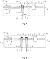
- Figure 1 shows an embodiment for an optical roughness sensor 10 according to the invention.
- the roughness sensor 10 has a beam coupling device 11, which is designed here as a fiber coupling 11a (e.g. ferrule) with an optical system (e.g. lens arrangement) and provides the coupling and decoupling of optical radiation.
- the useful radiation is guided into the sensor 10 by means of an optical fiber.
- the measuring principle of the roughness sensor 10 is based on the interference of signals with a reference signal R, which is provided by a local oscillator.
- the local oscillator can be provided by a reflection of the input radiation on the end face of the beam coupling device 11 or ferrule 11a of the optical fiber (end face 11b).
- the end face (exit face) is the To understand beam coupling arrangement 11 as a reference oscillator element.
- the local oscillator is formed by a reflective surface 14 (reference oscillator element) on the beam splitter 13.
- the reference oscillator element 14 is then arranged on the beam splitter 13.
- an exit surface of the beam splitter 13 can form the reference oscillator element 14 by vapor deposition of a reflective layer.
- this design can simplify the data evaluation. Changes in distance detected in this regard contain direct roughness information for the measured surface.
- the measuring principle of the roughness sensor 10 is based in particular on the known technique of optical coherence tomography, with light of a specific coherence length being used for distance measurement by means of interferometry.
- the measurement radiation used is preferably tuned over a specific frequency range.
- the measuring range is essentially determined by the coherence length of the measuring radiation used and thus e.g. limited by the laser beam source used.
- the beam splitter 13 creates a separation of a reference beam path for the local oscillator and a decoupling path of a measuring beam decoupler 12.
- the measuring beam decoupler 12 emits and focuses the measuring radiation 17 in the direction of an object to be measured and enables detection of corresponding measurement radiation reflected on the object.
- the measuring beam decoupler 12 thus provides a surface signal through the reflected measuring radiation.
- Coherent laser radiation is preferably used as the useful radiation, the reference signal component of which is caused to interfere with the reflected measurement radiation by the optical structure. Based on the interference of the reference signal with the surface signal, a roughness signal can thus be generated and provided.
- point-specific distance information to an object to be measured can be obtained from the superposition of the reference signal with the surface signal.
- This information can represent an absolute or relative distance between the roughness sensor 10 and a point on the object surface.
- the roughness sensor 10 also has a drive unit 16 which is connected to the measuring beam decoupler 12 by means of a piston 15 or a shaft.
- the measuring beam decoupler 12 and thus also the decoupling path can therefore be moved in a lateral direction x along a scan axis S by means of the drive unit 16. This enables an at least line-by-line scanning movement of the measuring radiation 17 over the object surface.
- the decoupling path is guided laterally over the object surface for a specific scan path, the roughness sensor 10 as a whole, ie in particular the housing 18 of the roughness sensor, in an unchanged position relative to the object surface remains.
- the measuring beam decoupler 12 reflections of the measuring radiation 17 from the surface and thus the surface signal are continuously detected.
- the surface signal is detected or processed together with the reference signal - also during the relative movement of the coupling-out path - at specific intervals or continuously.
- a lateral resolution of the surface profile can thus be influenced by the rate of signal processing.
- the detection of the signals can e.g. take place by means of one or more appropriately provided photodetectors.
- the detected signals can be processed by means of a downstream electronics or data processing unit.
- the reflective surface 14 can also provide at least one lateral position signal by means of a reflection of the useful radiation, by means of which the position of the measuring beam decoupler 12 can be determined and monitored in the x direction.
- the roughness profile of the measured surface can be derived two-dimensionally from the lateral position signal and the measurement signal 17, that is to say the roughness of a surface can be determined line by line.
- the relevant signals can be transported from the sensor 10 via the beam coupling device 11 and detected and / or processed further outside, for example by a coordinate measuring machine.
- a coordinate measuring machine for example, an embodiment with an optical detector arranged in the sensor 10 for signal detection or also with a processing unit on the sensor side is conceivable.
- Figure 2 shows a further embodiment of an optical roughness sensor 10 'according to the invention for a coordinate measuring machine. Identical or identically acting elements in different figures are provided with the same reference symbols.
- the senor 10 also has a beam coupling device 11, a first beam splitter 13, a reflective surface 14 for providing the lateral position signal and in particular the reference signal, a guide rod 15 and a drive unit 16.
- the components mentioned interact in a manner comparable to that described above , ie the decoupling channel 12 can be guided along the scan axis by means of the drive 16, with surface data being able to be recorded due to a reflection of the measuring beam portion 17.
- the roughness sensor 10 has an additional, second decoupling path 22 with a second beam passage window for bidirectional transmission of a first compensation component 27 of the measurement or useful radiation.
- the compensation radiation 27 is decoupled from the optical radiation fed into the sensor 10 'by means of a second beam splitter 23.
- the second beam splitter 23 has a 50% permeable or reflective coating. 50% of the supplied radiation is then decoupled as a compensation component 27 and 50% are used together for the measurement component 17 and the reference component.
- the first beam splitter 13 can have a 99% reflective coating, with 99% serving as a measuring part and 1% as a reference part.
- the second decoupling path 22 of the roughness sensor is provided with a fixed position relation relative to the latter, i.e. In contrast to the first decoupling path 12, the second such path 22 is arranged fixedly and immovably on the sensor (in particular in the sensor housing 18). The second decoupling path 22 thus provides a position-constant emission of the compensation beam component 27 with respect to the sensor 10.
- the signal of the local oscillator can alternatively or additionally be provided for this and all other shown embodiments of the invention by a first reflection at the end 11b of the fiber ferrule 11a (sleeve) (common path interferometry). All further reflexes can then interfere with this and / or a further LO reflex (LO: local oscillator).
- LO local oscillator
- a reference for the positioning of the roughness sensor 10 ′ relative to the object surface to be measured in the z-direction can be provided by the emission and the detection of the reflected compensation radiation 27.
- the first compensation signal that can be generated in this way represents a distance between the sensor 10 ′ and the object. Since the second decoupling path 22 remains unchanged in the lateral direction x, i. remains directed essentially at a fixed point of the object while the first decoupling path 12 is moved, changes in position can thereby be determined independently of a change in roughness.
- the first compensation signal enables the determination and calculation of oscillations or vibrations that occur in a coordinate measuring machine that carries the sensor 10 ′, in particular in the z direction. This happens on the assumption that during the roughness measurement with the moving measurement radiation 17, a distance measured via the second decoupling path 22 remains constant. If deviations or variations are found along this path, there is an undesired relative movement, which in turn can be processed with time resolution for the creation of a surface profile.
- Such vibrations can significantly influence the measured roughness of a surface and thus lead to a correspondingly faulty surface profile.
- a vibration-compensated surface profile can thus be calculated by continuously recording and taking into account the first compensation signal.
- This second embodiment thus provides a specific roughness sensor 10 'for use with a coordinate measuring machine (CMM), which can also compensate for any vibrations and oscillations that may occur in the CMM or provide the compensation.
- CMM coordinate measuring machine
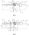
- the Figure 3 shows a further embodiment for a roughness sensor 10 ′′ according to the invention for preferred use with a coordinate measuring machine.
- the embodiment is again based on a sensor 10 according to FIG Figure 1 .
- the sensor 10 ′′ has a fixedly positioned reference component 31 extending parallel to the scan axis S.
- the reference component 31 can, for example, be in the form of a reflective surface, for example a mirror.
- a further beam splitter 33 is arranged, which decouples a Beam part 37 (scan compensation part) provides.
- the scan compensation component 37 is aligned with the reference component 31 and is reflected thereon. This provides an inner (second) compensation signal.
- the beam splitter 33 is connected to the coupling-out path 17 and is accordingly movable together therewith (in the x-direction).
- a distance between the movable decoupling path 12 and the reference element 31 can therefore be detected at a specific rate or also continuously.
- the arrangement of reference component 31 and beam splitter 33 can thus provide an internal compensation of the roughness sensor, wherein a linearity of the scanning movement of the first decoupling path 12 can be detected and monitored.
- the distance can be derived from a superposition of the reference signal with the internal compensation signal.
- a target distance is defined for the measurement with the roughness sensor 10 ′′, and if this is maintained, an error-free, linear scan movement can be deduced from the scanning movement along the scan axis of the first decoupling path 12.
- a possible offset, drift or vibrations of the moving measuring beam decoupler 12 can thus be detected and processed with the simultaneously detectable roughness values.
- the arrangement enables detection and compensation of (axial, z-direction) position errors of the inner sensor arrangement and thus also the measured surface profile.
- the amplitudes of the reflected signals provided by 14 and 31 can be selected to be several orders of magnitude smaller than for the reference signal. This can e.g. can be achieved by a low transmittivity (permeability) of the beam splitter 13.
- Figure 4 shows an embodiment for a roughness sensor 10 '''according to the invention, which is a combination of the approaches according to Figures 2 and 3 represents.
- a sensor 10 '' ' can be provided which can detect both internal scanning vibrations, e.g. caused by the drive unit 16, as well as external vibrations such as from a coordinate measuring machine (e.g. also by its drives) or other environmental influences.
- a coupled-in useful radiation can essentially be sufficient for generating these optical signals, with this useful radiation being able to be divided into the required portions in the sensor 10 '' ', i.e. Measurement component, first (external) and second (internal) compensation component and lateral position measurement component.
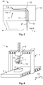
- Figure 5 shows a further embodiment of an optical roughness sensor 40 according to the invention for a coordinate measuring machine with optionally a distance reference element 41.
- the roughness sensor 40 has a beam coupling device 11, which is in turn designed here as a fiber coupling 11a with optics and provides the coupling and decoupling of optical radiation.
- the useful radiation is guided into the sensor 40 by means of an optical fiber.
- the local oscillator is provided by a reflection of the input radiation on the end face 11b of the ferrule 11a of the optical fiber.
- the roughness sensor 40 also has a coupling unit (not shown), by means of which a modular and repeated coupling of the sensor 40 to a coordinate measuring machine, in particular with repeatedly high-precision relative positioning, is made possible.
- the coupling unit can be designed for the transmission of optical and / or electrical signals.
- a beam deflecting element 13 ′ deflects the measurement radiation 17 within the housing 18.
- the measuring radiation can thereby be guided out of the sensor 40 on the underside of the housing 18 through a beam passage window 42. Reflected measurement radiation can be detected via the same path.
- the ferrule 11a or optical fiber can be guided as far as the beam passage window 42 and the end surface 11b (of the ferrule or the fiber) can form the beam passage window 42.
- a measurement can be carried out by specifically guiding the sensor 40 along the surface to be measured.
- a measuring path can in particular be defined on the basis of a known object shape or a known surface profile.
- the guiding is preferably carried out by means of a coordinate measuring machine, the sensor 40 being attached to a measuring head or to a suitable coupling of the CMM (modular). Maintaining a constant or highly precisely known distance between the surface and the sensor is preferred here. A deviation from this distance can lead to significant errors in a roughness measurement. In general, with such an expansion, an accuracy for the measurement can be achieved within the scope of the positioning accuracy of the CMM.
- a distance reference element 41 can optionally be provided on the sensor 40.
- the distance reference element 41 is here, for example, designed as a runner 41 and is used to be placed on a surface to be measured and to be moved over the surface for a measurement while maintaining the most extensive contact possible. In this way, a constant distance between the surface and the sensor 40 can be maintained during a measurement.
- Such a distance reference element 41 can advantageously also be used with a roughness sensor 10 of FIG Figure 1 conceivable.
- the sensor 10 can be placed on a surface by means of the distance reference element 41 A lateral movement can then take place not by moving the entire sensor 10 but by laterally offsetting the decoupling path 12 in the x direction by means of the drive 16.
- the distance reference element 41 may be provided by e.g. three-component pad be embodied, these e.g. has three curved (e.g. spherical or hemispherical) elements on the underside of the housing 18. This enables a 3-point support for the sensor to be provided.
- three-component pad be embodied, these e.g. has three curved (e.g. spherical or hemispherical) elements on the underside of the housing 18. This enables a 3-point support for the sensor to be provided.
- Figure 6 shows a coordinate measuring machine 1, exemplarily designed as a portal coordinate measuring machine 1.
- the coordinate measuring machine 1 has a base 2 on which a portal 3 is arranged such that it can be moved in a first direction (y-direction).
- the portal 3 has two portal supports, a bridge 4 and a rod or Z-column 5, the portal supports being connected to one another at their upper ends via the bridge 4.
- a slide 6 is arranged on the bridge 4 and can be moved along the bridge 4, ie in a second spatial direction (x-direction) connecting the two portal supports.
- the rod or z-column 5 can be moved in a third spatial direction (z-direction) and is guided in a receptacle of the slide 6.
- the Z column 5 is guided in bearings which are part of the slide 6.
- the three spatial directions x, y and z are aligned perpendicular to one another here, even if this is not a prerequisite for the present invention.
- the coordinate measuring machine 1 is provided for the determination of one or a plurality of measuring points on an object 9 and therefore has three linear guide mechanisms to enable the movement of a sensor 10 arranged on the z column 5 in the three spatial directions x, y and z relative to the base 2 on.
- the sensor 10 is arranged by means of an interface 7 for the modular reception of different sensors on the lower free end of the z-column 5 facing the base 2.
- the senor 10 is supplied with useful optical radiation by means of an optical fiber 8.
- the optical fiber 8 also provides a transmission of the signals measured by the sensor 10 out of the sensor 10.
- Corresponding detectors for the signals and signal processing are provided on the coordinate measuring machine 1.
- the transmission of the optical radiation can alternatively also be provided in an integrated manner in the interface 7.
- Each linear guide mechanism has an assigned guide (in the x, y or z directions).
- each linear guide mechanism has an assigned measuring element for determining the position in the assigned guiding direction, for example measuring scales for determining positions in the x, y or z directions or linear encoder.
- the measuring head is provided with a roughness sensor 10 according to the invention Figure 1 Mistake.
- a roughness sensor 10 according to the invention Figure 1 Mistake.
- different types of sensors can be recorded by means of the interface 7, such as tactile sensors with which mechanical contact is established with an object surface to be measured, or contactless measuring sensors, such as capacitive, inductive and optical sensors.
- the different sensors can also be kept in an exchange unit (not shown) and exchanged automatically, i.e. coupled to the interface 7 and uncoupled from the interface 7.
- the invention is not limited to portal coordinate measuring machines, as in FIG Figure 1 shown. Rather, any known type of coordinate measuring machine which enables object surface measurement with an optical sensor is suitable for the invention.
- the coordinate measuring machine 1 also has a control and processing unit with a processor and a data carrier. By means of the control and processing unit, in particular drives of the coordinate measuring machine 1 are controlled and the measurement data are stored and processed.
- the control and processing unit is preferably designed to enable fully automatic measurement of object surfaces.
- control and processing unit can also be connected to a user console, in particular wirelessly e.g. via radio.
Description
Die Erfindung betrifft einen optischen Rauheitssensor zum Erfassen einer Oberflächeninformation und eine Koordinatenmessmaschine (CMM) zur Rauheitsvermessung einer Objektoberfläche mittels eines solchen Sensors.The invention relates to an optical roughness sensor for detecting surface information and a coordinate measuring machine (CMM) for measuring the roughness of an object surface by means of such a sensor.
In vielen technischen Anwendungsbereichen besteht das Bedürfnis, Oberflächen von Objekten und damit auch die Objekte selbst mit hoher Genauigkeit zu vermessen. Dieses gilt insbesondere für die fertigende Industrie, für die das Vermessen und Überprüfen von Oberflächen von Werkstücken hohe Bedeutung, insbesondere auch zu Zwecken der Qualitätskontrolle, hat.In many technical fields of application there is a need to measure surfaces of objects and thus also the objects themselves with high accuracy. This applies in particular to the manufacturing industry, for which the measurement and checking of surfaces of workpieces is of great importance, especially for quality control purposes.
Für diese Anwendungen werden üblicherweise Koordinatenmessmaschinen eingesetzt, welche eine präzise Vermessung der Geometrie einer Objektoberfläche, typischerweise mit Mikrometer-Genauigkeit, ermöglichen. Zu vermessende Objekte können beispielsweise Motorblöcke, Getriebe und Werkzeuge sein. Bekannte Koordinatenmessmaschinen vermessen die Oberfläche, indem ein mechanischer Kontakt hergestellt und die Oberfläche abgetastet wird. Beispiele hierfür sind Portalmessmaschinen, wie sie z.B. in der
Im Stand der Technik wird mit solchen Koordinatenmessgeräten als Standardmesssensor ein optischer oder taktiler Sensor verwendet, welcher beispielsweise aus einer Rubinkugel besteht, die auf einem Messstab montiert ist. Die Auslenkung des taktilen Sensors, im Falle einer für dreidimensionale Messungen ausgelegten Koordinatenmessmaschine in drei zueinander senkrechten Richtungen X, Y und Z, wird bei der Abtastung über ein Schaltelement oder wegmessendes Element bestimmt. Anhand des Schaltpunkts oder Auslenkungswegs werden der Ort des Kontakts und damit die Oberflächenkoordinaten berechnet.In the prior art, such coordinate measuring machines are used as the standard measuring sensor with an optical one or tactile sensor is used, which for example consists of a ruby ball that is mounted on a dipstick. The deflection of the tactile sensor, in the case of a coordinate measuring machine designed for three-dimensional measurements, in three mutually perpendicular directions X, Y and Z, is determined during scanning via a switching element or a displacement measuring element. The location of the contact and thus the surface coordinates are calculated using the switching point or deflection path.
Zur Rekonstruktion des Oberflächenprofils aus den Messdaten müssen die mechanischen Abmessungen des Sensors selbst und dessen Ausrichtung beim Kontakt mit der Objektoberfläche berücksichtigt werden. Der Sensor ist ausgebildet mit einer Messspitze bekannter Geometrie, typischerweise sphärisch oder für spezielle Anwendungen ellipsoidal, typischerweise mit einem (Haupt-)Radius in der Grössenordnung einiger Millimeter. Der Begriff "Messspitze" ist im Zusammenhang mit der vorliegenden Erfindung allgemein zu verstehen als (taktiler) Messsensor jeder beliebigen Form und Ausdehnung, wobei dieser nicht zwingend eine spitz zulaufende Form aufweisen muss (jedoch kann). Die mit der Koordinatenmessmaschine unter Verwendung eines taktilen Sensors gemessenen Rohdaten stellen die gemessenen Ortskoordinaten eines Bezugspunkts der Messspitze, beispielsweise des Messspitzen-Zentrums, dar.To reconstruct the surface profile from the measurement data, the mechanical dimensions of the sensor itself and its alignment when it comes into contact with the object surface must be taken into account. The sensor is designed with a measuring tip of known geometry, typically spherical or, for special applications, ellipsoidal, typically with a (main) radius on the order of a few millimeters. In connection with the present invention, the term “measuring tip” is to be understood in general as a (tactile) measuring sensor of any shape and extension, whereby this does not necessarily have to (but can) have a tapered shape. The raw data measured with the coordinate measuring machine using a tactile sensor represent the measured spatial coordinates of a reference point of the measuring tip, for example the measuring tip center.
Bedingt durch die physikalischen Abmessungen der Messspitze des taktilen Sensors ist jedoch die Messungsauflösung beschränkt. Die physikalische Abmessung der Messspitze bzw. die damit verbundene limitierte Messungsauflösung führen zu einem "Glättungseffekt" bei der Vermessung rauer Oberflächen: Während Erhebungen oder Spitzen einer Objektoberfläche nahezu perfekt bzw. objektgetreu gemessen werden können, kann die Messspitze des taktilen Sensors aufgrund ihrer physikalischen Ausdehnung nicht in enge Vertiefungen einer Objektoberfläche eindringen. Dieses bewirkt eine Glättung des gemessenen Oberflächenprofils in einer nichtlinearen Art, indem die Messdaten von vertieften Oberflächenbereichen geglättet sind, während die Messdaten erhabener Oberflächenbereiche nahezu objektgetreu sind. Für ingenieur-technische Aspekte ist dieses sogar oft vorteilhaft, weil, insbesondere für eine flächige Verbindung von Oberflächen zweier Objekte, oft eine genaue Kenntnis von deren erhabenen Bereichen wichtiger als die genaue Bestimmung enger vertiefter Oberflächenbereiche ist.Due to the physical dimensions of the measuring tip of the tactile sensor, the measurement resolution is limited. The physical dimensions of the measuring tip and the limited measurement resolution associated with it lead to a "smoothing effect" when measuring rough surfaces: while elevations or tips of an object surface are measured almost perfectly or true to the object the measuring tip of the tactile sensor cannot penetrate into narrow recesses on an object surface due to its physical expansion. This brings about a smoothing of the measured surface profile in a non-linear manner in that the measurement data of recessed surface areas are smoothed, while the measurement data of raised surface areas are almost true to the object. For engineering-technical aspects this is even often advantageous because, in particular for a two-dimensional connection of surfaces of two objects, precise knowledge of their raised areas is often more important than the precise determination of more closely recessed surface areas.
Andererseits ist die Auflösung taktiler Messungen, insbesondere für eine genauere Vermessung von Oberflächenvertiefungen aus den vorgenannten methodeninhärenten Limitierungen, für viele neue Anwendungen nicht mehr ausreichend.On the other hand, the resolution of tactile measurements, in particular for a more precise measurement of surface depressions from the aforementioned method-inherent limitations, is no longer sufficient for many new applications.
Die
Deshalb werden im Stand der Technik inzwischen Ansätze zur berührungslosen Vermessung, insbesondere mit optischen Sensoren, verfolgt. Mittels eines optischen Sensors mit einem ausgesandten Messlichtstrahl, insbesondere von einem Laser, können auch Oberflächenvertiefungen sehr genau vermessen werden, solange der Fokus des Messlichtstrahls, zu vergleichen mit der Messspitze eines taktilen Sensors, auf der Objektoberfläche nicht grösser als die Struktur von deren Vertiefungen ist. Die Auflösung optischer Messverfahren kann demzufolge deutlich höher sein, als diejenige taktiler Messverfahren für eine genaue Vermessung von Oberflächenprofilen, insbesondere von deren Vertiefungen. Demzufolge unterscheidet sich ein mit einem optischen Sensor erstelltes Profil von einem mit einem taktilen Sensor erstellten Profil einer und derselben Objektoberfläche. Auch ein mit einem optischen Sensor erstelltes Oberflächenprofil stellt, ebenso wie ein mit einem taktilen Sensor erstelltes Oberflächenprofil, jedoch eine, basierend auf den physikalischen Abmessungen der "Messspitze", in ihrer Auflösung gefilterte Abbildung der tatsächlichen Objektoberfläche dar, wobei die Abmessungen der optischen "Messspitze" im Vergleich zu der Messspitze eines taktilen Sensors als gegen die Wellenlänge der optischen Messstrahlung konvergierend angesehen werden können bzw. vernachlässigbar sind. Deswegen sind optische Sensoren und Messverfahren für eine Koordinatenmessmaschine geeignet, prinzipiell eine wirklich objektgetreue Vermessung eines Oberflächenprofils bereitzustellen.Therefore, approaches to contactless measurement, in particular with optical sensors, are now being pursued in the prior art. Surface depressions can also be measured very precisely by means of an optical sensor with an emitted measuring light beam, in particular from a laser, as long as the focus of the measuring light beam, compared with the measuring tip of a tactile sensor, on the object surface is not larger than the structure of its depressions. The resolution more optical The measuring method can therefore be significantly higher than that of the tactile measuring method for a precise measurement of surface profiles, in particular of their depressions. Accordingly, a profile created with an optical sensor differs from a profile created with a tactile sensor one and the same Object surface. A surface profile created with an optical sensor, just like a surface profile created with a tactile sensor, however, represents a resolution-filtered image of the actual object surface based on the physical dimensions of the "measuring tip", the dimensions of the optical "measuring tip "In comparison to the measuring tip of a tactile sensor, they can be viewed as converging towards the wavelength of the optical measuring radiation or are negligible. Therefore, optical sensors and measuring methods for a coordinate measuring machine are suitable in principle to provide a surface profile that is really true to the object.
Optische Sensoren bzw. Messverfahren für eine Koordinatenmessmaschine sind mit einer Reihe von Vorteilen verbunden: Die Messung erfolgt kontaktlos, und der optische Sensor kann schneller als ein taktiler Sensor über eine Objektoberfläche geführt werden, mit einer geringeren physikalischen Abmessung der "Messspitze", wodurch eine höhere laterale Auflösung der Messung ermöglicht wird.Optical sensors and measuring methods for a coordinate measuring machine are associated with a number of advantages: The measurement is contactless, and the optical sensor can be moved faster than a tactile sensor over an object surface, with a smaller physical dimension of the "measuring tip", resulting in a higher one lateral resolution of the measurement is made possible.
Trotzdem beinhalten nicht nur mit taktilen, sondern auch mit optischen Sensoren erstellte Oberflächenprofile immer auch Merkmale, die nicht von der vermessenen Oberfläche stammen, sondern durch das Messverfahren bedingt sind. Beispielsweise sind aus der
Die Messergebnisse optischer Sensoren, insbesondere für interferometrische Messverfahren, werden oft nachteilig durch Phasenrauschen oder Speckle-Effekte beeinflusst. Abhängig von der Rauheit der Objektoberfläche kann beispielsweise die Phase des von einer Oberfläche reflektierten Lichts in einer solchen Weise verändert werden, dass eine zu einem angepeilten Objektpunkt gemessene Distanz falsch ist. Als Folge solcher lokalen optischen Störeinflüsse weisen mit optischen Sensoren vermessene Oberflächenprofile oft Messfehler auf, wie beispielsweise virtuelle singuläre, aber in der Objektoberfläche nicht existierende Spitzen oder Vertiefungen.The measurement results of optical sensors, especially for interferometric measurement methods, are often disadvantageous influenced by phase noise or speckle effects. Depending on the roughness of the object surface, for example, the phase of the light reflected from a surface can be changed in such a way that a distance measured to a targeted object point is incorrect. As a result of such local optical interference, surface profiles measured with optical sensors often have measurement errors, such as virtual singular peaks or depressions that do not exist in the object surface.
Zur Rauheitsmessung werden heute vorwiegend stationäre, taktile Messgeräte verwendet. Der Prüfling wird hierbei auf einem Messtisch platziert und eine Nadel wird unter Kontakt mit der Oberfläche linear über das Objekt geführt. Dabei können Höhenveränderungen der Nadel registriert werden und daraus ein Höhenprofil abgeleitet werden. Wie oben erwähnt, hängt die Messauflösung auch hier von der Nadelgeometrie ab.Stationary, tactile measuring devices are mainly used to measure roughness today. The test object is placed on a measuring table and a needle is guided linearly over the object in contact with the surface. Changes in the height of the needle can be registered and a height profile can be derived from this. As mentioned above, the measurement resolution also depends on the needle geometry.
Ein Nachteil einer solchen Vorrichtung liegt in dem Erfordernis, dass das Werkstück hierfür auf den Messtisch gebracht werden muss. In Abhängigkeit der Werkstückgrösse und - form kann dies sehr aufwändig und zeitintensiv sein. Jüngere Ansätze schlagen daher die Kombination eines spezifischen Rauheitssensors mit einer Koordinatenmessmaschine vor, um einen Transport des Prüflings vermeiden zu können.A disadvantage of such a device is the requirement that the workpiece must be brought onto the measuring table for this purpose. Depending on the size and shape of the workpiece, this can be very complex and time-consuming. More recent approaches therefore propose the combination of a specific roughness sensor with a coordinate measuring machine in order to be able to avoid transporting the test object.
Als solcher Sensor ist beispielsweise der "BMT MiniProfiler" von Breitmeier Messtechnik GmbH bekannt. Der Sensor kann als Wechselsystem in einem Magazin zur wiederholten An- und Abkopplung an eine CMM bereitgestellt werden. Die Ansteuerung sowie Auswertung kann direkt in der CMM Bedieneroberfläche erfolgen. Der Sensor wird mit der Objektoberfläche in Kontakt gebracht. Die CMM bleibt während der nachfolgenden Rauheitsmessung im Stillstand, d.h. der Sensor als Ganzes wird relativ zum Objekt nicht bewegt. Die Nadel des Sensors wird in diesem Zustand über die Oberfläche geführt. Hierdurch können durch die CMM verursachte Vibrationen vermindert werden.The "BMT MiniProfiler" from Breitmeier Messtechnik GmbH is known as such a sensor. The sensor can be provided as an interchangeable system in a magazine for repeated coupling and uncoupling to a CMM will. The control and evaluation can take place directly in the CMM user interface. The sensor is brought into contact with the object surface. The CMM remains stationary during the subsequent roughness measurement, ie the sensor as a whole is not moved relative to the object. In this state, the sensor's needle is guided over the surface. This can reduce vibrations caused by the CMM.
Dennoch können verbleibende, externe Vibration seitens der CMM oder durch andere Umwelteinflüsse verursachte Positionsfehler nicht ausgeschlossen werden und das Messergebnis negativ beeinflussen. Ferner kann es zu nichtlinearen Effekten bei der Bewegung der Nadel (Bewegung von Massen) kommen, die mit dem Sensor nicht berücksichtigbar sind.However, remaining external vibrations on the part of the CMM or position errors caused by other environmental influences cannot be ruled out and have a negative impact on the measurement result. Furthermore, there may be non-linear effects in the movement of the needle (movement of masses) which cannot be taken into account with the sensor.
Ein weiterer Nachteil für diese Rauheitserfassung und das zu prüfende Werkstück ist der dabei bestehende mechanische Kontakt zwischen Sensor und Werkstück. Hierdurch können ungewollte Veränderungen der Oberfläche eintreten, insbesondre bei empfindlichen Werkstückoberflächen, z.B. Spezialbeschichtungen.Another disadvantage for this roughness detection and the workpiece to be tested is the mechanical contact that exists between the sensor and the workpiece. This can lead to undesired changes in the surface, especially in the case of sensitive workpiece surfaces, e.g. Special coatings.
Eine Aufgabe der Erfindung ist daher die Bereitstellung eines verbesserten Rauheitssensors, wobei mit dem Sensor die oben genannten Probleme gelöst werden können.One object of the invention is therefore to provide an improved roughness sensor, the above-mentioned problems being able to be solved with the sensor.
Im Besonderen ist es Aufgabe der vorliegenden Erfindung einen verbesserten Rauheitssensor, insbesondere hinsichtlich Verlässlichkeit und Genauigkeit von Erfassten Messdaten, zur Verwendung mit einer Koordinatenmessmaschine vorzusehen.In particular, it is the object of the present invention to provide an improved roughness sensor, in particular with regard to the reliability and accuracy of acquired measurement data, for use with a coordinate measuring machine.
Diese Aufgaben werden durch die Verwirklichung der kennzeichnenden Merkmale der unabhängigen Ansprüche gelöst. Merkmale, die die Erfindung in alternativer oder vorteilhafter Weise weiterbilden, sind den abhängigen Patentansprüchen zu entnehmen.These objects are achieved by implementing the characterizing features of the independent claims. Features which develop the invention in an alternative or advantageous manner can be found in the dependent claims.
Der Erfindung liegt die Idee zu Grunde anstelle eines standardmässig kontaktierenden Sensors einen solchen mit einem verringerten Einfluss auf die zu messenden Oberfläche bereitzustellen.The invention is based on the idea of providing a sensor with a reduced influence on the surface to be measured instead of a standard contacting sensor.
Die Erfindung beruht im Unterschied zum Stand der Technik auf einem optischen Messprinzip zur Erfassung von Rauheiten einer Oberfläche. Das bevorzugte Prinzip basiert auf der Interferenz von unterschiedlichen Signalen, die seitens des Sensors bereitgestellt werden können. Ausserdem wird die Heranziehung des Ansatzes der optischen Kohärenztomographie für die Auswertung der Signale und die Ableitung eines Oberflächenprofils vorgeschlagen.In contrast to the prior art, the invention is based on an optical measuring principle for detecting roughness of a surface. The preferred principle is based on the interference of different signals that can be provided by the sensor. It is also proposed to use the optical coherence tomography approach for evaluating the signals and deriving a surface profile.
Die Erfindung betrifft einen optischen, insbesondere interferometrisch messenden, Rauheitssensor für eine Koordinatenmessmaschine, mit einer Strahlkopplungseinheit zur Einkopplung von optischer Nutzstrahlung und insbesondere Auskopplung von unterschiedlichen Interferenzsignalen und mit einem lokalen Referenzoszillatorelement zur Bereitstellung eines Referenzpfads und eines interferometrischen Referenzsignals mittels eines Referenzstrahlungsanteils der Nutzstrahlung. Das Referenzoszillatorelement kann hierdurch einen lokalen Oszillator (LO) bereitstellen.The invention relates to an optical, in particular interferometrically measuring, roughness sensor for a coordinate measuring machine, with a beam coupling unit for coupling in optical useful radiation and in particular decoupling different interference signals and with a local reference oscillator element for providing a reference path and an interferometric reference signal by means of a reference radiation component of the useful radiation. The reference oscillator element can thereby provide a local oscillator (LO).
Der Rauheitssensor verfügt zudem über einen ersten Auskoppelpfad mit einem ersten Strahldurchtrittsfenster zur bidirektionalen Transmission eines Messstrahlungsanteils der Nutzstrahlung. Das Strahldurchtrittsfenster kann z.B. durch eine Optik oder ein Aussparung am Sensorgehäuse gebildet sein. Vielmehr ist das Strahldurchtrittsfenster jedoch generisch zu verstehen und stellt unabhängig von dessen Ausgestaltung eine Emission von Strahlung aus dem Sensor heraus und den Empfang von reflektierter Strahlung bereit.The roughness sensor also has a first decoupling path with a first beam passage window bidirectional transmission of a measurement radiation component of the useful radiation. The beam passage window can be formed, for example, by optics or a recess on the sensor housing. Rather, however, the beam passage window is to be understood generically and, regardless of its configuration, provides an emission of radiation from the sensor and the reception of reflected radiation.
Mittels des ersten Auskoppelpfads ist der Messstrahlungsanteil auf eine zu vermessende Objektoberfläche ausrichtbar und eine Reflexion an der Objektoberfläche des Messstrahlungsanteils erfassbar, wobei durch den reflektierten Messstrahlungsanteil ein Oberflächensignal bezüglich der Objektoberfläche bereitstellbar ist. Das Oberflächensignal enthält dabei insbesondere eine Information bezüglich einer aktuellen Entfernung zur Objektoberfläche.By means of the first coupling-out path, the measurement radiation component can be aligned with an object surface to be measured and a reflection on the object surface of the measurement radiation component can be detected, with the reflected measurement radiation component being able to provide a surface signal with respect to the object surface. The surface signal contains, in particular, information relating to a current distance to the object surface.
Der Referenzpfad und der Auskoppelpfad sind ausserdem derart angeordnet, dass das Referenzsignal und das Oberflächensignal interferieren und basierend auf der Interferenz von Referenzsignal und Oberflächensignal ein Rauheitssignal ableitbar ist. Die Anordnung ist so gewählt, dass die Interferenz bei einer Bewegung des Auskoppelpfads bestehen bleibt, d.h. über eine durch die Bewegbarkeit des Auskoppelpfads definierte Scanstrecke (fortwährend) gegeben ist.The reference path and the decoupling path are also arranged in such a way that the reference signal and the surface signal interfere and a roughness signal can be derived based on the interference of the reference signal and the surface signal. The arrangement is chosen so that the interference persists when the coupling-out path moves, i.e. is given over a scan path defined by the mobility of the decoupling path (continuously).
Mit dieser Vorrichtung kann ein axialer Abstand (in Richtung der optischen Emissionsstrahlachse bzw. z-Achse) zwischen dem Rauheitssensor und einem Punkt der Messoberfläche gemessen werden.With this device, an axial distance (in the direction of the optical emission beam axis or z-axis) between the roughness sensor and a point on the measuring surface can be measured.
Wird der Messstrahl nun zusätzlich entlang eines Scanpfades oder einer Scanachse, z.B. parallel zu oder mit einem gleich bleibenden Abstand zu einer zu vermessenden Oberfläche, bewegt und werden dabei mit einer bestimmten Frequenz oder fortlaufend Abstandsdaten erfasst, so kann damit ein Oberflächenprofil (axiale Abstandswerte über eine laterale Positionsveränderung entlang der Scanachse) für die abgescannte Strecke erstellt werden. Der Messstrahl wird hierfür quer (seitlich) zu dessen Ausbreitungs- bzw. Emissionsrichtung, also lateral bezüglich einer Messstrahlrichtung, bewegt.If the measuring beam is now additionally along a scan path or a scan axis, e.g. parallel to or with a constant distance to a surface to be measured, and if distance data are recorded with a certain frequency or continuously, a surface profile (axial distance values via a lateral position change along the scan axis) can be created for the scanned route. For this purpose, the measuring beam is moved transversely (laterally) to its direction of propagation or emission, that is to say laterally with respect to a measuring beam direction.
Für eine solche scannende Rauheitsmessung einer Objektoberfläche ist die Kenntnis oder die Bestimmung eines Abstands oder einer Abstandsänderung zwischen dem Sensor und der Oberfläche während der Messung vorteilhafterweise gegeben. Ohne eine diesbezügliche Information kann die optische Rauheitsmessung teilweise stark fehlerbehaftet sein, beispielsweise aufgrund von unerwarteten äusseren Einflüssen (z.B. Stösse) oder unerwünschten Abweichung vom vorgesehenen Scanpfad.For such a scanning roughness measurement of an object surface, knowledge or determination of a distance or a change in distance between the sensor and the surface is advantageously given during the measurement. Without any information in this regard, the optical roughness measurement can sometimes be highly error-prone, for example due to unexpected external influences (e.g. shocks) or undesired deviation from the intended scan path.
Die Bewegung des Auskoppelpfads über das Objekt kann auf unterschiedliche Weisen erfolgen. Einerseits kann der Rauheitssensor gekoppelt an eine Koordinatenmessmaschine (CMM) entlang eines definierten Pfades automatisch und motorisiert geführt werden. Ist der Oberflächenverlauf des zu messenden Objekts bekannt, kann der Scanpfad für den Rauheitssensor entsprechend angepasst definiert werden. Eine Messgenauigkeit für die daraus resultierenden Rauheitswerte liegt hierbei im Rahmen der Mess- bzw. Führungsgenauigkeit der CMM.The movement of the decoupling path over the object can take place in different ways. On the one hand, the roughness sensor, coupled to a coordinate measuring machine (CMM), can be guided automatically and motorized along a defined path. If the surface profile of the object to be measured is known, the scan path for the roughness sensor can be defined accordingly. A measurement accuracy for the resulting roughness values lies within the scope of the measurement or guidance accuracy of the CMM.
Alternativ oder auch zusätzlich kann der Rauheitssensor ein in einer festen Positionsrelation relativ zu der Strahlkopplungseinheit (oder Sensorgehäuse) angeordnetes Abstandsreferenzelement aufweisen. Das Abstandsreferenzelement ist dabei zur oberflächenkontaktierenden Führung des Rauheitssensors und zur Bereitstellung eines konstanten Abstands zur Objektoberfläche während einer Rauheitsmessung ausgebildet. Das Abstandsreferenzelement kann hierzu z.B. kufenartig ausgebildet sein, so dass eine (quasi) gleitende Berührung und Führung über die Oberfläche ermöglicht wird. Beispielsweise weist eine Ausführungsform als Kufe eine reibungsarme Oberflächenbeschichtung auf. Denkbar ist ferner eine Drei-Punkt-Auflage mit drei gekrümmten (z.B. kugelförmigen) Auflageelementen.Alternatively or also in addition, the roughness sensor can have a distance reference element arranged in a fixed positional relationship relative to the beam coupling unit (or sensor housing). The distance reference element is designed to guide the roughness sensor with surface contact and to provide a constant distance to the object surface during a roughness measurement. The distance reference element can e.g. Be designed like a runner, so that a (quasi) sliding contact and guidance over the surface is made possible. For example, an embodiment as a runner has a low-friction surface coating. A three-point support with three curved (e.g. spherical) support elements is also conceivable.
In anderen Worten kann das Abstandsreferenzelement (z.B. Kufe oder Halbkugeln) für eine Messung auf die zu messende Oberfläche aufgesetzt werden, der Sensor durch eine gesteuerte Bewegung des CMM-Messkopfs (an welchem der Rauheitssensor angekoppelt ist) unter Beibehaltung des Kontakts zwischen Abstandsreferenzelement und Oberflächen über die Oberfläche bewegt werden und die Erfassung von Abstandsdaten mit dem Rauheitssensor fortlaufend ausgeführt werden.In other words, the distance reference element (e.g. skid or hemispheres) can be placed on the surface to be measured for a measurement, the sensor via a controlled movement of the CMM measuring head (to which the roughness sensor is coupled) while maintaining contact between the distance reference element and surfaces the surface can be moved and the acquisition of distance data with the roughness sensor is carried out continuously.
In beiden oben beschriebenen Varianten kann der laterale Oberflächenversatz anhand der durch die Koordinatenmessmaschine bereitgestellten Positionsdaten (Koordinaten) bestimmt und für die Erstellung eines Rauheitsprofils herangezogen werden.In both of the variants described above, the lateral surface offset can be determined on the basis of the position data (coordinates) provided by the coordinate measuring machine and used for the creation of a roughness profile.
Die Bestimmung von Abständen mit dem Sensor kann mittels optischer Messtechniken basierend auf einer durchgestimmten optischen Kohärenztotographie (OCT) erfolgen. Diese erlauben eine Entfernungsbestimmung über einen verhältnismässig grossen Bereich, nur begrenzt durch die Kohärenzlänge der verwendeten Laserstrahlung. Durch die Verteilung von entsprechenden optischen Signalen (siehe unten) auf unterschiedliche Reflektionspunkte (innerhalb und ausserhalb des Sensors) ist es möglich unterschiedliche Entfernung gemeinsam (gleichzeitig) zu erfassen bzw. zu überwachen.The determination of distances with the sensor can be based on optical measurement techniques based on a tuned optical coherence tomography (OCT). These allow the distance to be determined over a relatively large area, only limited by the coherence length of the laser radiation used. By distributing appropriate optical signals (see below) to different reflection points (inside and outside the sensor), it is possible to detect or monitor different distances together (at the same time).
Durch das Führen des Rauheitssensors mittels der CMM zur Messung eines Oberflächenprofils können z.B. vermehrt Vibrationen im System auftreten, die ein erhöhtes Fehlerrisiko für die Rauheitsdaten zur Folge haben können. Zur Vermeindung einer CMM Bewegung während der Messung und damit zu einer zu erwartenden Steigerung der Messgenauigkeit und Messverlässlichkeit weist der Rauheitssensor eine (innere) Antriebseinheit zur Bewegung des ersten Auskoppelpfads auf. Die Antriebseinheit ist dabei derart mit dem ersten Auskoppelpfad gekoppelt, dass der erste Auskoppelpfad - und damit die emittierte Messstrahlung - relativ zur Strahlkopplungseinheit parallel oder koaxial entlang einer Scanachse (in x-Richtung) über eine definierte Scanstrecke hinweg gesteuert bewegbar ist. Die Bewegung erfolgt quer, insbesondere orthogonal, zur Emissionsrichtung des Messstrahlungsanteils durch das Strahldurchtrittsfenster. Die Bewegung erfolgt in Sinne der vorliegenden Erfindung damit lateral bezüglich dieser Emissionsrichtung und typischerweise ebenso lateral über eine zu vermessenden Oberfläche.By guiding the roughness sensor using the CMM to measure a surface profile, for example, increased vibrations can occur in the system, which can result in an increased risk of errors in the roughness data. To avoid a CMM movement during the measurement and thus to an expected increase in the measurement accuracy and measurement reliability, the roughness sensor has an (inner) drive unit for moving the first decoupling path. The drive unit is coupled to the first decoupling path in such a way that the first decoupling path - and thus the emitted measurement radiation - can be moved in a controlled manner relative to the beam coupling unit parallel or coaxially along a scan axis (in the x direction) over a defined scanning path. The movement takes place transversely, in particular orthogonally, to the emission direction of the measurement radiation component through the beam passage window. In the sense of the present invention, the movement thus takes place laterally with respect to this emission direction and typically also laterally over a surface to be measured.
"Lateral" wird im Kontext dieser Erfindung bezüglich der Emissionsrichtung der Messstrahlung des Sensors verstanden, also seitlich (quer) zu dieser Emissionsachse und z.B. insbesondere auch in Richtung der Scanachse."Lateral" is understood in the context of this invention with respect to the emission direction of the measuring radiation of the sensor, i.e. laterally (transversely) to this emission axis and e.g. especially in the direction of the scan axis.
Die lateralen Positionen des Auskoppelpfads bzw. der emittierten Messstrahlung können beispielsweise mittels eine Schrittmotors verfolgt und bestimmt werden. Der Antrieb kann zur Positionserfassung in x-Richtung alternativ oder zusätzlich mit einem Linearencoder versehen sein.The lateral positions of the coupling-out path or the emitted measurement radiation can be tracked and determined, for example, by means of a stepper motor. The drive can alternatively or additionally be provided with a linear encoder for position detection in the x direction.
Bei solch einer Rauheitsmessung kann der Rauheitssensor in einer bestimmten Position und Orientierung relativ zu dem Objekt unverändert gehalten werden. Die laterale Messstrecke in x-Richtung wird dann insbesondere allein durch ein Verstellen des Auskoppelpfads mittels des Antriebs bereitgestellt. Denkbar ist jedoch auch eine Überlagerung aus einer Bewegung des Messkopfs der CMM, also des dabei angekoppelten Rauheitssensors, und der inneren Antriebseinheit.With such a roughness measurement, the roughness sensor can be kept unchanged in a certain position and orientation relative to the object. The lateral measurement section in the x direction is then provided in particular solely by adjusting the decoupling path by means of the drive. However, it is also conceivable that a movement of the measuring head of the CMM, that is to say of the roughness sensor coupled to it, and the inner drive unit can be superimposed.
In einer Ausführungsform weist der optische Rauheitssensor einen lateralen Positionspfad zur Breitstellung eines lateralen Positionssignals bezüglich einer Scanachsenposition des Auskoppelpfads auf, wobei der laterale Positionspfad durch eine Reflexion eines Lateralstrahlungsanteils der Nutzstrahlung definiert ist. Es kann also ein Teil der Nutzstrahlung dazu verwendet werden die laterale x-Position für das Rauheitsprofil zu bestimmen. Für jeden Höhenwert in z-Richtung kann ein zugeordneter Positionswert in x-Richtung bestimmt werden. Die Daten können einander zugeordnet werden und aus den Wertepaaren können entsprechende Oberflächenkoordinaten und damit ein Profil abgeleitet werden.In one embodiment, the optical roughness sensor has a lateral position path for providing a lateral position signal with respect to a scan axis position of the coupling-out path, the lateral position path being defined by a reflection of a lateral radiation component of the useful radiation. A part of the useful radiation can therefore be used to determine the lateral x-position for the roughness profile. For each height value in the z direction, an assigned position value in the x direction can be determined. The data can be assigned to each other and from the Pairs of values can be derived from corresponding surface coordinates and thus a profile.
Das laterale Positionssignal kann ebenfalls mit dem Referenzsignal zur Interferenz gebracht werden, wobei anhand dieser Interferenz die laterale Positionsänderung (also die x-Koordinate des Rauheitsprofils) festgestellt werden kann.The lateral position signal can also be brought into interference with the reference signal, with the lateral change in position (that is to say the x coordinate of the roughness profile) being able to be determined on the basis of this interference.
Gemäss einer spezifischen Ausführungsform kann der Rauheitssensor einen ersten Strahlteiler aufweisen, wobei der erste Strahlteiler eine zumindest teilweise Trennung des Auskoppelpfads (Messstrahlungsanteil) und des lateralen Positionspfads (Strahlungsanteil zur Bestimmung der x-Position) bereitstellt, insbesondere eine Trennung des Lateralstrahlungsanteils und des Messstrahlungsanteils.According to a specific embodiment, the roughness sensor can have a first beam splitter, the first beam splitter providing an at least partial separation of the decoupling path (measurement radiation component) and the lateral position path (radiation component for determining the x position), in particular a separation of the lateral radiation component and the measurement radiation component.
Der Strahlteiler kann insbesondere ein spezifisches Durchlässigkeitsniveau aufweisen (z.B. 5%), um das reflektierte Messsignal von dem reflektierten lateralen Positionssignal möglichst eindeutig trennen zu können. Es können also z.B. 95% reflektiert werden und dem Auskoppelpfad zur Verfügung stehen und 5% transmittieren und als Lateralsignal reflektiert werden. Dies ist für die Auswertung und Identifikation der unterschiedlichen Signale vorteilhaft.The beam splitter can in particular have a specific permeability level (e.g. 5%) in order to be able to separate the reflected measurement signal from the reflected lateral position signal as clearly as possible. So e.g. 95% are reflected and are available to the decoupling path and 5% are transmitted and reflected as a lateral signal. This is advantageous for the evaluation and identification of the different signals.
Der optische Rauheitssensor kann zudem eine reflektierende Fläche, insbesondere einen Spiegel, zur Bereitstellung der Reflexion des Lateralstrahlungsanteils aufweisen. Die reflektierende Fläche kann insbesondere direkt an dem ersten Strahlteiler angeordnet oder aufgedampft sein. Alternativ kann der Spiegel in einem separiert ausgeformten Strahlengang, z.B. in Freistrahloptik oder mittels einer optischen Faser, angeordnet sein.The optical roughness sensor can also have a reflective surface, in particular a mirror, for providing the reflection of the lateral radiation component. The reflective surface can in particular be arranged directly on the first beam splitter or it can be vapor-deposited. Alternatively, the mirror can be molded separately Beam path, for example in free-beam optics or by means of an optical fiber, can be arranged.
In einer Ausführungsform ist das Referenzoszillatorelement durch eine Endfläche einer Ferrule (Hülse), insbesondere der Strahlkopplungseinheit, bereitgestellt. Hier kann am Rand der Ferrule ein erster Teilreflex der eingebrachten Nutzstrahlung (z.B. werden etwas 4% der Nutzstrahlung reflektiert) auftreten. Dieser Teilreflex erzeugt ein lokales Oszillatorsignal (Referenzsignal) und repräsentiert damit eine Art Referenzposition.In one embodiment, the reference oscillator element is provided by an end face of a ferrule (sleeve), in particular the beam coupling unit. A first partial reflection of the introduced useful radiation can occur at the edge of the ferrule (e.g. around 4% of the useful radiation is reflected). This partial reflex generates a local oscillator signal (reference signal) and thus represents a kind of reference position.
Das Referenzoszillatorelement kann alternativ durch die an dem ersten Strahlteiler angeordnete reflektierende Fläche repräsentiert sein, wobei dann das Signal für den lokalen Oszillator durch einen Reflex eines Teils der Nutzstrahlung bereitgestellt ist. Beispielsweise kann ein Strahlteiler eine 5%ige Durchlässigkeit aufweisen und die tranmittierende Strahlung auf die reflektierende Fläche geführt werden.The reference oscillator element can alternatively be represented by the reflective surface arranged on the first beam splitter, in which case the signal for the local oscillator is provided by a reflection of part of the useful radiation. For example, a beam splitter can have a 5% transmission and the transmitting radiation can be guided onto the reflective surface.
Mit der vorliegenden Erfindung ist es ausserdem möglich unterschiedliche Einflüsse, die eine Genauigkeit einer Rauheitsmessung beeinflussen können, zu überwachen und zu kompensieren.The present invention also makes it possible to monitor and compensate for different influences that can influence the accuracy of a roughness measurement.
Ein Haupteinfluss kann von der Koordinatenmessmaschine, sogar im Stillstand der CMM, kommen. Aufgrund der Luftlager und der naturgemäss begrenzten Steifigkeit der CMM können fast dauernd Vibrationsfrequenzen von einigen Hertz und kleine Amplituden auftreten. Diese haben typischerweise einen vernachlässigbaren Einfluss für die Messpunktbestimmung, jedoch sind die Auswirkungen auf eine Rauheitsmessung signifikant. Ein anderer Einfluss beruht auf der begrenzten Stabilität des internen Antriebs des Sensors, wodurch z.B. (laterale und/oder axiale) Schwingungen während der Bewegung auftreten können. Der interne Antrieb des Sensors kann auch durch Nichtlinearitäten negativ beeinflusst seinA main influence can come from the coordinate measuring machine, even when the CMM is at a standstill. Due to the air bearings and the naturally limited rigidity of the CMM, vibration frequencies of a few Hertz and small amplitudes can occur almost continuously. These typically have a negligible influence on the measurement point determination, but the effects on a roughness measurement are significant. Another influence is based on the limited stability of the internal drive of the sensor, which for example (lateral and / or axial) vibrations can occur during the movement. The internal drive of the sensor can also be negatively influenced by non-linearities
Für eine Kompensation von eventuell auftretenden Störeinflüssen auf eine Messung kann der Rauheitssensor erfindungsgemäss eine Signalkompensationsanordnung zur Bereitstellung von zumindest einem Kompensationssignal aufweisen.In order to compensate for any interfering influences that may occur on a measurement, the roughness sensor can according to the invention have a signal compensation arrangement for providing at least one compensation signal.
Zum einen kann eine Information bezüglich einer Messposition des Rauheitssensors relativ zu der Objektoberfläche, insbesondere bezüglich eines Abstands zwischen Rauheitssensor und Objektoberfläche, durch ein erstes Kompensationssignal bereitstellbar sein. Hierdurch kann ein Versatz des Rauheitssensors während einer Rauheitsmessung detektiert und berücksichtigt werden. Als Versatz ist dabei auch eine Vibration oder Schwingung des Sensors während einer Messung zu verstehen.On the one hand, information relating to a measurement position of the roughness sensor relative to the object surface, in particular relating to a distance between the roughness sensor and the object surface, can be provided by a first compensation signal. In this way, an offset of the roughness sensor can be detected and taken into account during a roughness measurement. An offset is also to be understood as a vibration or oscillation of the sensor during a measurement.
Zum zweiten kann mittels der Signalkompensationsanordnung eine Kompensationsinformation bezüglich einer relativen Positionierung des Auskoppelpfads in einem Rauheitssensorgehäuse durch ein zweites Kompensationssignal bereitstellbar sein. Hierbei kann ein möglicher interner Versatz für die Messstrahlauskopplung, z.B. ein ungewünschter axialer oder lateraler Versatz des Auskoppelpfads, detektiert und berücksichtigt werden. Auch interne Schwingungen, die beispielsweise durch die Antriebseinheit verursacht werden können, können hierbei erfasst werden.Secondly, by means of the signal compensation arrangement, compensation information relating to a relative positioning of the coupling-out path in a roughness sensor housing can be provided by a second compensation signal. A possible internal offset for the coupling-out of the measuring beam, for example an undesired axial or lateral offset of the coupling-out path, can be detected and taken into account. Internal vibrations, which can be caused by the drive unit, for example, can also be recorded here.
In einem OCT-Tomogramm (Fourier-transformiertes Interferogramm) können die einzelnen detektierten Signale und damit messbaren Entfernungen durch Bandpass-Filterung getrennt werden und dann als einzelne Distanzwerte weiterverarbeitet werden. Hierdurch können alle relevanten Entfernungen gleichzeitig gemessen und hinsichtlich eventueller Messstörungen (z.B. Vibration der CMM oder interne Antriebsfehler) synchronisiert werden.In an OCT tomogram (Fourier-transformed interferogram), the individual detected signals and thus measurable distances can be separated by bandpass filtering and then further processed as individual distance values. This means that all relevant distances can be measured at the same time and synchronized with regard to possible measurement errors (e.g. vibration of the CMM or internal drive errors).
Die (bereits kompensierten) Rauheitsdaten können dann durch eine angepasste Kombination der gemessenen Signale extrahiert werden.The (already compensated) roughness data can then be extracted by an adapted combination of the measured signals.
Generell ermöglicht die Bandpass-Filterung eine Trennung einzelner Abstände in dem Rauheitssensor und damit die individuelle Weiterverbreitung und Zuordnung der jeweiligen Signale. Hierfür können die Strecken der einzelnen Strahlpfade (Auskoppelpfad, Referenzpfad, lateraler Kompensationspfad und Scankompensationspfad) durch entsprechende Anordnung der jeweiligen Reflexionsflächen unterschiedlich eingerichtet sein. Ein Übersprechen von Signalen kann so verhindert und eine Eindeutigkeit für die Auswertung bereitgestellt werden.In general, the bandpass filtering enables the separation of individual distances in the roughness sensor and thus the individual propagation and assignment of the respective signals. For this purpose, the routes of the individual beam paths (decoupling path, reference path, lateral compensation path and scan compensation path) can be set up differently by appropriate arrangement of the respective reflection surfaces. Crosstalk of signals can thus be prevented and clarity can be provided for the evaluation.
In einer Ausführungsform weist die Signalkompensationsanordnung einen zweiten Auskoppelpfad mit einem zweiten Strahldurchtrittsfenster auf, wobei eine bidirektionale Transmission eines ersten Kompensationsanteils der Nutzstrahlung, insbesondere parallel zum Messstrahlungsanteil, bereitgestellt ist. Der erste Kompensationsanteil kann auf das zu vermessende Objekt ausgerichtete werden und eine Reflexion an dem Objekt des ersten Kompensationsanteils kann damit entsprechend erfassbar sein. Durch den reflektierten ersten Kompensationsanteil ist das erste Kompensationssignal bereitstellbar.In one embodiment, the signal compensation arrangement has a second decoupling path with a second beam passage window, bidirectional transmission of a first compensation component of the useful radiation, in particular parallel to the measurement radiation component, being provided. The first compensation component can be aligned with the object to be measured and a reflection on the object of the first compensation component can thus be correspondingly detectable. Through the reflected first The first compensation signal can be provided as a compensation component.
Insbesondere ist der zweite Auskoppelpfad positionsfest relativ zur Strahlkopplungseinheit, insbesondere positionsfest relativ zu dem Rauheitssensorgehäuse, angeordnet.In particular, the second decoupling path is arranged in a fixed position relative to the beam coupling unit, in particular in a fixed position relative to the roughness sensor housing.
Während der erste Auskoppelpfad für eine Messung also in einer lateralen x-Richtung bewegt wird, um ein zeilenweises Erfassen der Objektoberfläche zu ermöglichen, bleibt der zweite Auskoppelpfad dabei in einer unveränderten Position relativ zu der Objektoberfläche (für die Messung wird der gesamte Sensor in eine fixe Position relativ zum zu vermessenden Objekt gebracht und dort gehalten). Es können hierdurch via den zweiten Pfad fortlaufend Daten zu im Wesentlichen einem Punkt der Oberfläche abgeleitet werden, wobei insbesondere der Abstand zu diesem Punkt überwachbar ist. Durch die Abstandsüberwachung können auftretende Vibrationen des Rauheitssensors erfasst werden und mit den via den ersten Auskoppelpfad gemessenen Profildaten verrechnet werden. Die feststellbaren axialen Vibrationen treten in aller Regel entsprechend auch für den Messpfad der Messstrahlung auf, weshalb eine solche Kompensation sehr genau und mit hoher Verlässlichkeit für die Rauheitsdaten sein kann.While the first decoupling path is moved in a lateral x-direction for a measurement in order to enable line-by-line detection of the object surface, the second decoupling path remains in an unchanged position relative to the object surface (for the measurement, the entire sensor is in a fixed position Position relative to the object to be measured and held there). In this way, data can be continuously derived via the second path on essentially one point on the surface, with the distance to this point in particular being able to be monitored. Due to the distance monitoring, vibrations of the roughness sensor that occur can be recorded and offset against the profile data measured via the first decoupling path. As a rule, the ascertainable axial vibrations also occur correspondingly for the measurement path of the measurement radiation, which is why such a compensation can be very precise and with high reliability for the roughness data.
Der Rauheitssensor kann entsprechend einen, die Auskopplung des ersten Kompensationsanteils aus der Nutzstrahlung bereitstellenden, zweiten Strahlteiler, mit z.B. einem 50%igen Reflexionsniveau, aufweisen.The roughness sensor can correspondingly have a second beam splitter providing the coupling out of the first compensation component from the useful radiation, with e.g. a 50% reflection level.
In einer Ausführungsform weist die Signalkompensationsanordnung eine sich parallel oder koaxial zur Scanachse erstreckende Referenzkomponente auf. Die Referenzkomponente kann beispielsweise als reflektierendes Element (Spiegel) ausgebildet sein. Hierzu kann eine Auskopplung eines Scankompensationsanteils aus der Nutzstrahlung entlang eines Scankompensationspfads bereitgestellt werden, wobei der Scankompensationspfad mit dem ersten Auskoppelpfad verbunden und mittels der Antriebseinheit gemeinsam mit dem ersten Auskoppelpfad entlang der Scanachse bewegbar angeordnet ist. Es ist zudem eine Reflexion des Scankompensationsanteils an der Referenzkomponente für zumindest einen Teil einer Scanstrecke (definiert durch z.B. eine mit dem ersten Auskoppelpfad abfahrbare Wegstrecke) und durch den reflektierten Scankompensationsanteil als zweites Kompensationssignal bereitstellbar.In one embodiment, the signal compensation arrangement has a parallel or reference component extending coaxially to the scan axis. The reference component can for example be designed as a reflective element (mirror). For this purpose, a scan compensation component can be decoupled from the useful radiation along a scan compensation path, the scan compensation path being connected to the first decoupling path and being arranged movably along the scan axis by means of the drive unit together with the first decoupling path. A reflection of the scan compensation component on the reference component can also be provided for at least part of a scan path (defined by, for example, a path that can be covered with the first decoupling path) and by the reflected scan compensation component as a second compensation signal.
Diese Ausführung der Signalkompensationsanordnung stellt eine gemeinsame Bewegung des Kompensationspfads mit dem Messpfad bereit. Die beiden Pfade sind so kombiniert, dass ein fester Positions- und Orientierungsbezug hergestellt ist. Die Referenzkomponente ist z.B. fest mit dem Sensorgehäuse verbunden. Hierdurch wird die Überwachung einer eventuellen ungewünschten Positionsabweichung des Auskoppelpfads und damit des Messpfads und Messsignals mittels der Kompensationsanordnung ermöglicht.This embodiment of the signal compensation arrangement provides a joint movement of the compensation path with the measurement path. The two paths are combined in such a way that a fixed position and orientation reference is established. The reference component is e.g. firmly connected to the sensor housing. This enables a possible undesired position deviation of the coupling-out path and thus of the measurement path and measurement signal to be monitored by means of the compensation arrangement.
Für die Auskopplung des Scankompensationsanteils aus der Nutzstrahlung kann der Rauheitssensor einen diese Auskopplung bereitstellenden dritten Strahlteiler aufweisen.For decoupling the scan compensation component from the useful radiation, the roughness sensor can have a third beam splitter providing this output.
Gemäss einer Ausführungsform der Erfindung kann die Signalkompensationsanordnung derart angeordnet sein, dass das erste und/oder das zweite Kompensationssignal mit dem Referenzsignal interferieren und basierend auf einer Interferenz von
- Referenzsignal mit Oberflächensignal und
- Referenzsignal mit erstem Kompensationssignal und/oder
- Referenzsignal mit zweitem Kompensationssignal ein kompensiertes Rauheitssignal ableitbar ist.
- Reference signal with surface signal and
- Reference signal with first compensation signal and / or
- Reference signal with a second compensation signal, a compensated roughness signal can be derived.
Aus der Interferenz aus Referenzsignal und Oberflächensignal kann das "rohe" Oberflächen- oder Rauheitsprofil (unter zusätzlicher Berücksichtigung zugeordneter x-Positionen) abgeleitet werden. Es werden axiale Abstände (z-Komponente des Oberflächenprofils) über eine abgefahrene Scanstrecke (x-Komponente des Oberflächenprofils) erfasst.The "raw" surface or roughness profile (with additional consideration of assigned x positions) can be derived from the interference from the reference signal and the surface signal. Axial distances (z component of the surface profile) are recorded over a scanned path (x component of the surface profile).
Wahlweise oder gesamthaft kann entsprechend zusätzlich eine Interferenz aus Referenzsignal mit erstem Kompensationssignal und/oder eine Interferenz aus Referenzsignal mit zweitem Kompensationssignal mitberücksichtigt werden.Optionally or in total, an interference from the reference signal with the first compensation signal and / or an interference from the reference signal with the second compensation signal can also be taken into account.
Die Interferenz aus Referenzsignal mit dem ersten Kompensationssignal liefert direkt Kompensationsdaten bezüglich externen Einflüssen auf den Sensor, die eine Positionsbeeinflussung des Sensors während der Messung zugänglich und korrigierbar machen. Es können fortlaufend Abstände zwischen dem Sensor und der Oberfläche gemessen und die Messwerte mit den Daten für das rohe Oberflächenprofil verrechnet werden. Vibrationen des Sensors werden so fortlaufend und zuverlässig kompensiert.The interference from the reference signal with the first compensation signal directly supplies compensation data with regard to external influences on the sensor, which make a position influencing of the sensor accessible and correctable during the measurement. The distances between the sensor and the surface can be measured continuously and the measured values can be offset against the data for the raw surface profile. Vibrations from the sensor are continuously and reliably compensated for.
Die Interferenz aus Referenzsignal mit dem zweiten Kompensationssignal liefert eine direkte Information bezüglich innerer Messzustände des Sensors und damit innere Kompensationsdaten. Hierdurch kann z.B. ein lineares, paralleles Führen des Auskoppelpfads bezüglich der Scanachse überwacht oder eine innere Schwingung oder Vibration erfasst werden. Etwaige Abweichungen können aus diesem Interferenzsignal abgeleitete und mit den Daten für das rohe Oberflächenprofil verrechnet werden. Damit ist eine Kompensation für innere Störeinflüsse bereitgestellt.The interference from the reference signal with the second compensation signal provides direct information about internal measurement states of the sensor and thus internal ones Compensation data. In this way, for example, linear, parallel guidance of the coupling-out path with respect to the scan axis can be monitored or an internal oscillation or vibration can be detected. Any deviations can be derived from this interference signal and offset against the data for the raw surface profile. This provides compensation for internal interference.
Insbesondere ist das Referenzoszillatorelement in einer festen Positionsrelation relativ zu dem ersten Auskoppelpfad angeordnet und gemeinsam mit dem ersten Auskoppelpfad bewegbar.In particular, the reference oscillator element is arranged in a fixed positional relation relative to the first decoupling path and can be moved together with the first decoupling path.
In einer Ausführungsform weist der Rauheitssensor eine optische und/oder mechanische Schnittstelle auf, insbesondere eine integrierte optisch-mechanische Schnittstelle, wobei die Schnittstelle eine bidirektionale Übertragung von optischer Strahlung zwischen dem Rauheitssensor und einer Koordinatenmessmaschine und/oder eine Energieübertragung zu dem Rauheitssensor bereitstellt.In one embodiment, the roughness sensor has an optical and / or mechanical interface, in particular an integrated optical-mechanical interface, the interface providing a bidirectional transmission of optical radiation between the roughness sensor and a coordinate measuring machine and / or an energy transmission to the roughness sensor.
Beispielsweise kann der Rauheitssensor über einen internen Energiespeicher zum Antrieb der Antriebseinheit verfügen, der durch die Schnittstelle aufgeladen werden kann, insbesondere z.B. dann wenn der Rauheitssensor in einem Wechselmagazin für eine Messung vorgehalten wird. Alternativ oder zusätzlich stellt die Schnittstelle eine Stromversorgung des Sensors für und während einer Messung bereit.For example, the roughness sensor can have an internal energy store for driving the drive unit, which can be charged through the interface, in particular e.g. when the roughness sensor is held in a changeable magazine for a measurement. Alternatively or additionally, the interface provides a power supply for the sensor for and during a measurement.
Der optische Schnittstellenteil kann eine spezifische und robuste Kupplung zur vielfachen An- und Abkoppeln des Sensors aufweisen.The optical interface part can have a specific and robust coupling for multiple coupling and uncoupling of the sensor.
Die Erfindung betrifft auch eine Koordinatenmessmaschine zur Erfassung einer Oberflächeninformation bezüglich eines zu vermessenden Objekts. Die Koordinatenmessmaschine weist eine Basis, eine Schnittstelle zum Anordnen eines Messsensors für die Erfassung der Oberflächeninformation und eine Führung zur Bereitstellung einer Relativbewegung der Schnittstelle relativ zur Basis in zumindest eine Richtung, insbesondere in zwei oder drei Richtungen, auf. Zudem ist ein Steuerungs- und Verarbeitungseinheit vorgesehen.The invention also relates to a coordinate measuring machine for acquiring surface information relating to an object to be measured. The coordinate measuring machine has a base, an interface for arranging a measuring sensor for the acquisition of the surface information and a guide for providing a relative movement of the interface relative to the base in at least one direction, in particular in two or three directions. A control and processing unit is also provided.
Die Koordinatenmessmaschine weist erfindungsgemäss eine Rauheitsmessfunktionalität auf, bei deren Ausführung gesteuert durch die Steuerungs- und Verarbeitungseinheit die Oberflächeninformation durch optisches Abtasten vermittels eines an der Schnittstelle angeordneten optischen Rauheitssensors (= Messsensor) erfassbar ist. Im Rahmen der Rauheitsmessfunktionalität wird der Rauheitssensor in eine definierte Position relativ zur Objektoberfläche bewegt und ein Scanvorgang durch eine Relativbewegung eines ersten Auskoppelpfads des Rauheitssensors ausgeführt, wobei ein Messstrahlungsanteil einer Nutzstrahlung auf eine zu vermessende Objektoberfläche emittiert und eine Reflexion des Messstrahlungsanteils an der Objektoberfläche erfasst wird und mittels eines durch den reflektierten Messstrahlungsanteil bereitgestellten Oberflächensignals bezüglich der Objektoberfläche ein ein Oberflächenprofil repräsentierender Datensatz als die Oberflächeninformation erzeugt wird. Der Messkopf wird während der Ausführung des Scanvorgangs in der definierten Position relativ zur Objektoberfläche gehalten.According to the invention, the coordinate measuring machine has a roughness measuring functionality, when it is executed, controlled by the control and processing unit, the surface information can be detected by optical scanning by means of an optical roughness sensor (= measuring sensor) arranged at the interface. As part of the roughness measurement functionality, the roughness sensor is moved into a defined position relative to the object surface and a scanning process is carried out by a relative movement of a first decoupling path of the roughness sensor, with a measurement radiation portion of a useful radiation being emitted onto an object surface to be measured and a reflection of the measurement radiation portion on the object surface being recorded and a data record representing a surface profile is generated as the surface information by means of a surface signal provided by the reflected measurement radiation component with respect to the object surface. The measuring head is held in the defined position relative to the object surface while the scanning process is being carried out.
Insbesondere ist der Rauheitssensor gemäss einer obigen Ausführungsform ausgebildet.In particular, the roughness sensor is designed according to an embodiment above.
Durch die Ausführung einer Rauheitsmessung mit der CMM kann eine vergleichsweise hochaufgelöste Oberflächeninformation für zumindest einen Teil des zu vermessenden Objekts gewonnen werden. Insbesondere kann das zeilenweise Erfassen des Rauheitsprofils mehrfach mit einem bestimmten Versatz, z.B. in kleinen Intervallen in eine Richtung orthogonal zur Scanachse, erfolgen. So kann nicht nur eine zweidimensionale Rauheitsbestimmung sondern eine (quasi) dreidimensionale Rauheitsbestimmung durchgeführt werden.By performing a roughness measurement with the CMM, comparatively high-resolution surface information can be obtained for at least part of the object to be measured. In particular, the line-by-line acquisition of the roughness profile can be performed several times with a certain offset, e.g. at small intervals in a direction orthogonal to the scan axis. Thus, not only a two-dimensional roughness determination but a (quasi) three-dimensional roughness determination can be carried out.
Die CMM vermag also zum einen eine typische Vermessung eines Objekt bereitzustellen und zudem eine Rauheitsbestimmung für einen Teil des Objekts. Beide Datensätze können zu einem gemeinsamen Datensatz zusammengefasst und/oder als ein Messmodel abgelegt werden.The CMM is therefore able to provide a typical measurement of an object and also a roughness determination for a part of the object. Both data records can be combined into a common data record and / or stored as a measurement model.
Ferner kann mittels der CMM eine Rauheitsmessung mit dem erfindungsgemässen Sensor einer bestimmten Position an einem Prüfling zugeordnet werden. So können die generell mit allein relativem Positionsbezug generierten Rauheitsprofile in einem übergeordneten Objekt-Koordinatensystem referenziert werden.Furthermore, a roughness measurement with the sensor according to the invention can be assigned to a specific position on a test object by means of the CMM. In this way, the roughness profiles generally generated with only a relative position reference can be referenced in a higher-level object coordinate system.
Die erfindungsgemässe Vorrichtung wird nachfolgend anhand von in den Zeichnungen schematisch dargestellten konkreten Ausführungsbeispielen rein beispielhaft näher beschrieben, wobei auch auf weitere Vorteile der Erfindung eingegangen wird. Im Einzelnen zeigen:
- Fig.1
- eine Ausführungsform für einen optischen Rauheitssensor gemäss der Erfindung;
- Fig.2
- eine weitere Ausführungsform für einen optischen Rauheitssensor gemäss der Erfindung;
- Fig.3
- eine weitere Ausführungsform für einen optischen Rauheitssensor gemäss der Erfindung;
- Fig.4
- eine weitere Ausführungsform für einen optischen Rauheitssensor gemäss der Erfindung;
- Fig.5
- eine weitere Ausführungsform für einen optischen Rauheitssensor gemäss der Erfindung; und
- Fig.6
- eine Koordinatenmessmaschine mit einem optischen Rauheitssensor gemäss der Erfindung.
- Fig.1
- an embodiment for an optical roughness sensor according to the invention;
- Fig. 2
- a further embodiment for an optical roughness sensor according to the invention;
- Fig. 3
- a further embodiment for an optical roughness sensor according to the invention;
- Fig. 4
- a further embodiment for an optical roughness sensor according to the invention;
- Fig. 5
- a further embodiment for an optical roughness sensor according to the invention; and
- Fig. 6
- a coordinate measuring machine with an optical roughness sensor according to the invention.
Der Rauheitssensor 10 weist eine Strahlkopplungsvorrichtung 11 auf, welche hier als eine Faserkopplung 11a (z.B. Ferrule) mit einer Optik (z.B. Linsenanordnung) ausgebildet ist und die Einkopplung und die Auskopplung von optischer Strahlung bereitstellt. Die Nutzstrahlung wird mittels einer optischen Faser in den Sensor 10 geführt.The
Das Messprinzip des Rauheitssensors 10 basiert auf der Interferenz von Signalen mit einem Referenzsignal R, das durch einen lokalen Oszillator bereitgestellt wird.The measuring principle of the
In einer Ausführung kann der lokale Oszillator durch eine Reflexion der Eingangsstrahlung an der Endfläche der Strahlkopplungsvorrichtung 11 oder Ferrule 11a der optischen Faser (Endfläche 11b) bereitgestellt sein. Hierbei ist die Endfläche (Austrittsfläche) der Strahlkopplungsanordnung 11 als Referenzoszillatorelement zu verstehen.In one embodiment, the local oscillator can be provided by a reflection of the input radiation on the end face of the
Es ist zudem denkbar, dass der lokale Oszillator durch eine reflektierende Fläche 14 (Referenzoszillatorelement) am Strahlteiler 13 gebildet wird. Das Referenzoszillatorelement 14 ist dann an dem Strahlteiler 13 angeordnet. Alternativ kann eine Austrittsfläche des Strahlteilers 13 durch Aufdampfen einer reflektierenden Schicht das Referenzoszillatorelement 14 bilden. Insbesondere da der Abstand entlang der optischen Achse von der Fläche 14 bis zum einem fokussierten, axialen Messpunkt der Messstrahlung 17 (z.B. Brennpunkt/Fokus der Messstrahlung) konstant ist, kann dieses Design die Datenauswertung vereinfachen. Diesbezüglich detektierte Abstandsänderungen enthalten eine direkte Rauheitsinformation für die vermessene Oberfläche.It is also conceivable that the local oscillator is formed by a reflective surface 14 (reference oscillator element) on the
Das Messprinzip des Rauheitssensors 10 beruht insbesondere auf der bekannten Technik der optischen Kohärenztomografie, wobei Licht einer bestimmten Kohärenzlänge zur Entfernungsmessung mittels Interferometrie eingesetzt wird. Vorzugsweise wird die verwendete Messstrahlung dabei über einen bestimmten Frequenzbereich durchgestimmt. Der Messbereich ist im Wesentlichen durch die Kohärenzlänge der verwendeten Messstrahlung und damit z.B. durch die eingesetzte Laserstrahlquelle limitiert.The measuring principle of the
Der Strahlteiler 13 schafft eine Trennung eines Referenzstrahlpfads für den lokalen Oszillator und eines Auskoppelpfads eines Messstrahlauskopplers 12. Der Messstrahlauskoppler 12 stellt eine Emission und Fokussierung der Messstrahlung 17 in Richtung eines zu vermessenden Objekts bereit und ermöglicht das Erfassen von entsprechend an dem Objekt reflektierter Messstrahlung. Der Messstrahlauskoppler 12 stellt somit ein Oberflächensignal durch die reflektierte Messstrahlung bereit.The
Als Nutzstrahlung wird vorzugsweise kohärente Laserstrahlung verwendet, wobei deren Referenzsignalanteil durch den optischen Aufbau mit der reflektierten Messstrahlung zur Interferenz gebracht wird. Basierend auf der Interferenz des Referenzsignals mit dem Oberflächensignal kann damit ein Rauheitssignal erzeugt und bereitgestellt werden.Coherent laser radiation is preferably used as the useful radiation, the reference signal component of which is caused to interfere with the reflected measurement radiation by the optical structure. Based on the interference of the reference signal with the surface signal, a roughness signal can thus be generated and provided.
In anderen Worten kann aus der Überlagerung des Referenzsignals mit dem Oberflächensignal eine punktuelle Entfernungsinformation zu einem zu vermessenden Objekt gewonnen werden. Diese Information kann einen absoluten oder relativen Abstand zwischen dem Rauheitssensor 10 und einem Punkt der Objektoberfläche repräsentieren.In other words, point-specific distance information to an object to be measured can be obtained from the superposition of the reference signal with the surface signal. This information can represent an absolute or relative distance between the
Der Rauheitssensor 10 verfügt zudem über eine Antriebseinheit 16, die mittels eines Kolbens 15 oder einer Welle mit dem Messstrahlauskoppler 12 verbunden ist. Der Messstrahlauskoppler 12 und damit auch der Auskoppelpfad können also in einer lateralen Richtung x entlang einer Scanachse S mittels der Antriebseinheit 16 bewegt werden. Hierdurch wird eine zumindest zeilenweise Scanbewegung der Messstrahlung 17 über die Objektoberfläche ermöglicht.The
Zur Erfassung eines Rauheitsprofils einer Objektoberfläche wird der Auskoppelpfad für eine bestimmte Scanstrecke lateral über die Objektoberfläche geführt, wobei der Rauheitssensor 10 gesamthaft, d.h. insbesondre das Gehäuse 18 des Rauheitssensors, relativ zur Objektoberfläche in einer unveränderten Positionierung verbleibt. Während der Bewegung des Messstrahlauskopplers 12 werden fortlaufend Reflexe der Messstrahlung 17 von der Oberfläche und damit das Oberflächensignal erfasst.To detect a roughness profile of an object surface, the decoupling path is guided laterally over the object surface for a specific scan path, the
Zur Detektion und Erfassung des Oberflächenprofils wird das Oberflächensignal zusammen mit dem Referenzsignal - ebenfalls während der Relativbewegung des Auskoppelpfads - in bestimmten Intervallen oder fortlaufend detektiert bzw. verarbeitet. Durch die Rate der Signalverarbeitung kann so eine laterale Auflösung des Oberflächenprofils beeinflusst werden. Die Detektion der Signale kann z.B. mittels eines oder mehrerer entsprechend vorgesehener Photodetektoren erfolgen. Die Verarbeitung der detektierten Signale kann mittels einer nachgeschalteten Elektronik oder Datenverarbeitungseinheit erfolgen.To detect and record the surface profile, the surface signal is detected or processed together with the reference signal - also during the relative movement of the coupling-out path - at specific intervals or continuously. A lateral resolution of the surface profile can thus be influenced by the rate of signal processing. The detection of the signals can e.g. take place by means of one or more appropriately provided photodetectors. The detected signals can be processed by means of a downstream electronics or data processing unit.
Die reflektierende Fläche 14 kann zudem durch einen Reflex der Nutzstrahlung zumindest ein laterales Positionssignal bereitstellen, mittels welchem die Position des Messstrahlauskopplers 12 in x-Richtung bestimmbar und überwachbar ist. Aus dem laterales Positionssignal und dem Messsignal 17 kann das Rauheitsprofil der gemessenen Oberfläche zweidimensional abgeleitet werden, also zeilenweise die Rauheit einer Oberfläche bestimmt werden.The
Die betreffenden Signale können via die Strahlkopplungsvorrichtung 11 aus dem Sensor 10 transportiert und ausserhalb, z.B. seitens einer Koordinatenmessmaschine, detektiert und/oder weiterverarbeitet werden. Alternativ ist eine Ausführung mit einem in dem Sensor 10 angeordneten optischen Detektor zur Signaldetektion oder auch einer sensorseitigen Verarbeitungseinheit denkbar.The relevant signals can be transported from the
Wie bereits mit der Ausführungsform nach
Der Rauheitssensor 10' weist einen zusätzlichen, zweiten Auskoppelpfad 22 mit einem zweiten Strahldurchtrittsfenster zur bidirektionalen Transmission eines ersten Kompensationsanteils 27 der Mess- bzw. Nutzstrahlung auf. Die Kompensationsstrahlung 27 wird mittels eines zweiten Strahlteilers 23 aus der in den Sensor 10' zugeführten optischen Strahlung ausgekoppelt. Beispielsweise weist der zweite Strahlteiler 23 eine 50% durchlässige bzw. reflektierende Beschichtung auf. 50% der zugeführten Strahlung werden dann als Kompensationsanteil 27 ausgekoppelt und 50% werden für den Messanteil 17 und den Referenzanteil gemeinsam verwendet. Der erst Strahlteiler 13 kann eine 99% reflektierende Beschichtung aufweisen, womit 99% als Mess- und 1% als Referenzteil dienen.The roughness sensor 10 'has an additional,
Der zweite Auskoppelpfad 22 des Rauheitssensors ist relativ zu diesem mit einer festen Positionsrelation vorgesehen, d.h. im Unterschied zu dem ersten Auskoppelpfad 12 ist der zweite solche Pfad 22 fest und unbeweglich an dem Sensor (insbesondere in dem Sensorgehäuse 18) angeordnet. Der zweite Auskoppelpfad 22 stellt somit eine positionskonstante Emission des Kompensationsstrahlanteils 27 bezüglich des Sensors 10 bereit.The
Das Signal des lokalen Oszillators kann für diese und sämtliche anderen gezeigten Ausführungsformen der Erfindung alternativ oder zusätzlich durch eine erste Reflexion am Ende 11b der Faser-Ferrule 11a (Hülse) bereitgestellt sein (common path interferometry). Alle weiteren Reflexe können dann mit diesem und/oder einem weitern LO-Reflex (LO: lokaler Oszillator) interferieren.The signal of the local oscillator can alternatively or additionally be provided for this and all other shown embodiments of the invention by a first reflection at the
Durch die Emission und das Erfassen der reflektierten Kompensationsstrahlung 27 kann eine Referenz für die Positionierung des Rauheitssensors 10' relativ zu der zu vermessenen Objektoberfläche in z-Richtung bereitgestellt werden. Das hierdurch erzeugbare erste Kompensationssignal repräsentiert einen Abstand des Sensors 10' zum Objekt. Da der zweite Auskoppelpfad 22 in lateraler Richtung x unverändert bleibt, d.h. im Wesentlichen auf einen festen Punkt des Objekts gerichtet bleibt, während der erste Auskoppelpfad 12 bewegt wird, können hierdurch Positionsveränderungen unabhängig von einer Rauheitsänderung festgestellt werden.A reference for the positioning of the
Das erste Kompensationssignal ermöglicht das Feststellen und Verrechnen von auftretenden Schwingungen oder Vibrationen einer Koordinatenmessmaschine, die den Sensor 10' trägt, insbesondere in z-Richtung. Dies erfolgt auf der Annahme, dass während der Rauheitsmessung mit der bewegten Messstrahlung 17 eine via den zweiten Auskoppelpfad 22 gemessene Entfernung konstant bleibt. Werden entlang diesem Pfad Abweichungen oder Variationen festgestellt, so liegt eine ungewünschte Relativbewegung vor, die wiederum für die Erstellung eines Oberflächenprofils zeitaufgelöst mitverarbeitet werden kann.The first compensation signal enables the determination and calculation of oscillations or vibrations that occur in a coordinate measuring machine that carries the
Solche Vibrationen können die gemessene Rauheit einer Oberfläche signifikant beeinflussen und dadurch zu einem entsprechend fehlerbehafteten Oberflächenprofil führen. Durch das fortlaufende Erfassen und Berücksichtigen des ersten Kompensationssignals kann somit ein vibrationskompensiertes Oberflächenprofil berechnet werden. Diese zweite Ausführungsform stellt somit einen spezifischen Rauheitssensor 10' für den Einsatz mit einer Koordinatenmessmaschine (CMM) bereit, der zudem eventuell auftretende Vibrationen und Schwingungen in der CMM zu kompensieren vermag bzw. die Kompensation bereitzustellen vermag.Such vibrations can significantly influence the measured roughness of a surface and thus lead to a correspondingly faulty surface profile. A vibration-compensated surface profile can thus be calculated by continuously recording and taking into account the first compensation signal. This second embodiment thus provides a specific roughness sensor 10 'for use with a coordinate measuring machine (CMM), which can also compensate for any vibrations and oscillations that may occur in the CMM or provide the compensation.
Die
Die Ausführungsform basiert wiederum auf einem Sensor 10 gemäss
Es kann also ein Abstand zwischen dem beweglichen Auskoppelpfad 12 und dem Referenzelement 31 in einer bestimmten Rate oder auch fortlaufend erfasst werden. Die Anordnung aus Referenzkomponente 31 und Strahlteiler 33 kann hiermit eine innere Kompensation des Rauheitssensors bereitstellen, wobei eine Linearität der Scanbewegung des ersten Auskoppelpfads 12 erfassbar und überwachbar ist. Aus einer Überlagerung des Referenzsignals mit dem inneren Kompensationssignal kann der Abstand abgeleitet werden.A distance between the
Insbesondere ist für die Messung mit dem Rauheitssensor 10" ein Sollabstand definiert, bei dessen Beibehaltung über die Scanbewegung entlang der Scanachse z.B. auf eine fehlerlose, lineare Scanbewegung geschlossen werden kann. Abweichung des Abstands können über die Scanposition aufgenommen werden und jeweilige Abstände können jeweiligen lateralen Positionen des ersten Auskoppelpfads 12 zugeordnet werden. Ein möglicher Versatz, Drift oder Vibrationen des bewegten Messstrahlauskopplers 12 können damit detektiert und mit den gleichzeitig erfassbaren Rauheitswerten verarbeitet werden. Die Anordnung ermöglicht also eine Erfassung und Kompensation von (axialen, z-Richtung) Positionsfehlern der inneren Sensoranordnung und damit auch des gemessenen Oberflächenprofils.In particular, a target distance is defined for the measurement with the
Um das Auftreten von parasitären Reflexen (durch ungewünschte Zwischen-Interferenzen) zu vermeiden bzw. gering zu halten, können die Amplituden der durch 14 und 31 bereitgestellten reflektierten Signale einige Grössenordnungen kleiner gewählt sein als für das Referenzsignal. Dies kann z.B. durch eine geringe Transmittivität (Durchlässigkeit) des Strahlteilers 13 erreicht werden.In order to avoid or minimize the occurrence of parasitic reflections (due to undesired interferences), the amplitudes of the reflected signals provided by 14 and 31 can be selected to be several orders of magnitude smaller than for the reference signal. This can e.g. can be achieved by a low transmittivity (permeability) of the
Durch ein solche Kombination der Ansätze können anhand der unterschiedlichen Signale sämtliche oben beschriebenen Konzepte in einem Rauheitssensor 10''' zusammen verwirklicht werden. Hierdurch kann ein Sensor 10''' bereitgestellt werden, der sowohl innere Scanningvibrationen, z.B. verursacht durch die Antriebseinheit 16, als auch externe Vibrationen wie von einer Koordinatenmessmaschine (z.B. ebenfalls durch deren Antriebe) oder anderen Umwelteinflüssen kompensierbar macht. Zudem kann für die Erzeugung dieser optischen Signale im Wesentlichen eine eingekoppelte Nutzstrahlung ausreichend sein, wobei diese Nutzstrahlung im Sensor 10''' in die benötigten Anteile aufgeteilt werden kann, d.h. Messanteil, erster (externer) und zweiter (interner) Kompensationsanteil und lateraler Positionsmessanteil.By combining the approaches in this way, all of the above-described concepts can be implemented together in a
Durch die Verwendung von entsprechend unterschiedlich teilreflektierenden Strahlteilern 13,23,33 können für die einzelnen Signale und Reflexe unterschiedliche Intensitäten definiert werden. Für die Auswertung dieser Signale können dann die jeweiligen (bekannten) Intensitätsniveaus berücksichtigt werden, wodurch eine Unterscheidung der Signale ermöglicht ist.By using correspondingly differently partially
Der Rauheitssensor 40 weist eine Strahlkopplungsvorrichtung 11 auf, welche hier wiederum als eine Faserkopplung 11a mit Optik ausgebildet ist und die Einkopplung und die Auskopplung von optischer Strahlung bereitstellt. Die Nutzstrahlung wird mittels einer optischen Faser in den Sensor 40 geführt. Der lokale Oszillator wird durch eine Reflexion der Eingangsstrahlung an der Endfläche 11b der Ferrule 11a der optischen Faser bereitgestellt.The
Der Rauheitssensor 40 weist zudem eine Kopplungseinheit (nicht gezeigt) auf, mittels derer eine modulare und wiederholte Ankopplung des Sensors 40 an eine Koordinatenmessmaschine, insbesondere mit wiederholt hochgenauer relativer Positionierung, ermöglicht ist. Die Kopplungseinheit kann zur Übertragung von optischen und/oder elektrischen Signalen ausgebildet sein.The
In der gezeigten Ausführung stellte ein Strahlumlenkelement 13' (z.B. Spiegel) eine Umlenkung der Messstrahlung 17 innerhalb des Gehäuses 18 bereit. Die Messstrahlung kann dadurch an der Unterseite des Gehäuses 18 durch ein Strahldurchtrittsfenster 42 aus dem Sensor 40 geführt werden. Reflektierte Messstrahlung ist über den gleichen Pfad erfassbar. Es versteht sich, dass anstelle des Umlenkmittels 13' die Ferrule 11a bzw. optische Faser bis zu dem Strahldurchtrittsfenster 42 geführt sein kann und die Endfläche 11b (der Ferrule oder der Faser) das Strahldurchtrittsfenster 42 bilden kann.In the embodiment shown, a
Mit einem solchen optischen Rauheitssensor 40 kann eine Messung durch gezieltes Führen des Sensors 40 entlang der zu messenden Oberfläche realisiert werden. Ein solcher Messpfad kann insbesondere anhand einer bekannten Objektform oder eines bekannten Oberflächenverlaufs definiert werden. Das Führen wird vorzugsweise mittels einer Koordinatenmessmaschine durchgeführt, wobei der Sensor 40 an einem Messkopf bzw. an einer geeignete Kopplung der CMM (modular) befestigt ist. Hierbei ist eine Beibehaltung eines konstanten bzw. hochgenau bekannten Abstands zwischen der Oberfläche und dem Sensor bevorzugt. Eine Abweichung dieses Abstands kann zu deutlichen Fehlern in einer Rauheitsmessung führen. Generell lässt sich mit einem solchen Ausbau eine Genauigkeit für die Messung im Rahmen der Positionierungsgenauigkeit der CMM erreichen.With such an
Ein Abstandsreferenzelement 41 kann optional an dem Sensor 40 vorgesehen sein. Das Abstandsreferenzelement 41 ist hier beispielhaft als Kufe 41 ausgebildet und dient dazu, auf einer zu vermessenden Oberfläche aufgesetzt und für eine Messung unter Beibehaltung eines möglichst flächigen Kontakts über die Oberfläche bewegt zu werden. So kann ein konstanter Abstand zwischen Oberfläche und Sensor 40 während einer Messung beibehalten werden.A
Eine Verwendung eines solchen Abstandsreferenzelements 41 ist vorteilhafterweise auch mit einem Rauheitssensor 10 der
In einer Ausführungsform kann das Abstandsreferenzelements 41 durch eine z.B. dreikomponentige Auflage verkörpert sein, wobei diese z.B. drei gekrümmte (z.B. sphärisch oder halb-kugelförmig) Elemente an der Unterseite des Gehäuses 18 aufweist. Hierdurch kann eine 3-Punk-Auflage für den Sensor bereitgestellt werden.In one embodiment, the
Die Koordinatenmessmaschine 1 weist eine Basis 2 auf, an der ein Portal 3 derart angeordnet ist, dass es in einer ersten Richtung (y-Richtung) bewegbar ist. Das Portal 3 weist zwei Portalträger, eine Brücke 4 und eine Stange oder Z-Säule 5 auf, wobei die Portalträger miteinander an ihren oberen Enden über die Brücke 4 verbunden sind.The coordinate measuring
Auf der Brücke 4 ist ein Schlitten 6 angeordnet, der entlang der Brücke 4, d.h. in einer die beiden Portalträger verbindenden zweiten Raumrichtung (x-Richtung) bewegbar ist. Die Stange oder z-Säule 5 ist in einer dritten Raumrichtung (z-Richtung) bewegbar und wird in einer Aufnahme des Schlittens 6 geführt. Für diese Bewegung in z-Richtung ist die Z-Säule 5 in Lagern geführt, welche Bestandteil des Schlittens 6 sind. Insbesondere sind die drei Raumrichtungen x, y und z hier senkrecht zueinander ausgerichtet, auch wenn dieses keine Voraussetzung für die vorliegende Erfindung ist.A slide 6 is arranged on the
Die Koordinatenmessmaschine 1 ist vorgesehen für die Bestimmung eines oder einer Vielzahl von Messpunkten auf einem Objekt 9 und weist daher drei lineare Führungsmechanismen zur Ermöglichung der Bewegung eines an der z-Säule 5 angeordneten Sensors 10 in den drei Raumrichtungen x, y und z relativ zur Basis 2 auf. Der Sensor 10 ist mittels einer Schnittstelle 7 zur modularen Aufnahme unterschiedlicher Sensoren an dem der Basis 2 zugewandten, unteren freien Ende der z-Säule 5 angeordnet.The coordinate measuring
Zudem ist der Sensor 10 mittels einer optischen Faser 8 mit optischer Nutzstrahlung versorgt. Die optische Faser 8 stellt zudem eine Übertragung der seitens des Sensors 10 gemessenen Signale aus dem Sensor 10 heraus bereit. Entsprechende Detektoren für die Signale und eine Signalverarbeitung sind an der Koordinatenmessmaschine 1 vorgesehen. Die Übertragung der optischen Strahlung kann alternativ auch integriert in der Schnittstelle 7 bereitgestellt sein.In addition, the
Jeder lineare Führungsmechanismus hat eine zugeordnete Führung (in x-, y- bzw. z-Richtung). Ausserdem weist jeder lineare Führungsmechanismus ein zugeordnetes Messelement zur Positionsbestimmung in der zugeordneten Führungsrichtung, beispielsweise Messskalen für Positionsbestimmungen in x-, y- bzw. z-Richtung oder Linearencoder, auf.Each linear guide mechanism has an assigned guide (in the x, y or z directions). In addition, each linear guide mechanism has an assigned measuring element for determining the position in the assigned guiding direction, for example measuring scales for determining positions in the x, y or z directions or linear encoder.
In dieser Ausführungsform ist der Messkopf mit einem erfindungsgemässen Rauheitssensor 10 gemäss
Die unterschiedlichen Sensoren können zudem in einer Auswechseleinheit (nicht gezeigt) vorgehalten werden und automatisch ausgetauscht, d.h. an die Schnittstelle 7 an- und von der Schnittstelle 7 abgekoppelt, werden.The different sensors can also be kept in an exchange unit (not shown) and exchanged automatically, i.e. coupled to the
Die Erfindung ist nicht beschränkt auf Portal-Koordinatenmessmaschinen, wie in
Die Koordinatenmessmaschine 1 weist ausserdem eine Steuerungs- und Verarbeitungseinheit, mit einem Prozessor und einem Datenträger auf. Mittels der Steuerungs- und Verarbeitungseinheit werden insbesondere Antriebe der Koordinatenmessmaschine 1 angesteuert und die Messdaten gespeichert und verarbeitet. Bevorzugt ist die Steuerungs- und Verarbeitungseinheit ausgebildet zur Ermöglichung einer vollautomatischen Vermessung von Objektoberflächen.The coordinate measuring
Für Zwecke direkter Benutzereingriffe oder direkter Benutzersteuerung kann die Steuerungs- und Verarbeitungseinheit auch mit einer Benutzer-Konsole verbunden sein, insbesondere Drahtlos z.B. via Funk.For purposes of direct user interventions or direct user control, the control and processing unit can also be connected to a user console, in particular wirelessly e.g. via radio.
Es versteht sich, dass diese dargestellten Figuren nur mögliche Ausführungsbeispiele schematisch darstellen. Die verschiedenen Ansätze können erfindungsgemäss ebenso miteinander sowie mit optischen Messkonzepten oder Koordinatenmessmaschinen des Stands der Technik kombiniert werden.It goes without saying that these illustrated figures only represent possible exemplary embodiments schematically. According to the invention, the various approaches can also be combined with one another and with optical measuring concepts or coordinate measuring machines of the prior art.
Claims (14)
- Optical roughness sensor (10, 10', 10", 10'", 40) for a coordinate measuring machine (1), comprising- a beam coupling unit (11) for coupling in optical useful radiation,- a local reference oscillator element designed to provide a reference path and an interferometric reference signal by means of a reference radiation component of the useful radiation, and- a first decoupling path (12) comprising a first beam passage window configured for bidirectional transmission of a measuring radiation component (17) of the useful radiation such thatwherein the reference path and the decoupling path (12) are arranged and interact such that the reference signal and the surface signal interfere and a roughness signal is derivable based on the interference of reference signal and surface signal.- the measuring radiation component (17) can be aligned onto an object (9) to be measured and a reflection of the measuring radiation component (17) can be acquired and- a surface signal with respect to an object surface can be provided by the reflected measuring radiation component (17),
characterized in that
the optical roughness sensor (10, 10', 10", 10'", 40) has a drive unit (16) for moving the first decoupling path (12), wherein the drive unit (16) is coupled to the first decoupling path (12) such that the first decoupling path (12) is movable in a controlled manner in parallel or coaxially along a scanning axis (S) in relation to the beam coupling unit (11). - Optical roughness sensor (10, 10', 10", 10'", 40) according to Claim 1,
characterized in that the roughness sensor (10, 10', 10", 10'", 40) has a lateral position path for providing a lateral position signal with respect to a scanning axis position of the decoupling path (12), wherein the lateral position path is defined by a reflection of a lateral radiation component of the useful radiation. - Optical roughness sensor (10, 10', 10", 10'", 40) according to Claim 2,
characterized in that the roughness sensor (10, 10', 10", 10'", 40) has a first beam splitter (13), wherein the first beam splitter (13) provides an at least partial separation of the decoupling path (12) and the lateral position path, in particular a separation of the lateral radiation component and the measuring radiation component. - Optical roughness sensor (10, 10', 10", 10'", 40) according to Claim 2 or 3,
characterized in that the roughness sensor (10, 10', 10", 10'", 40) has a reflective surface (14), in particular a mirror, for providing the reflection of the lateral radiation component, in particular wherein the reflective surface (14) is arranged on the first beam splitter (13). - Optical roughness sensor (10, 10', 10", 10'", 40) according to any one of Claims 1 to 4, characterized in that the reference oscillator element is provided by- an end face (11b) of a ferrule (11a), in particular of the beam coupling unit (11) or- the reflective surface (14) arranged on the first beam splitter.
- Optical roughness sensor (10, 10', 10", 10'", 40) according to any one of Claims 1 to 5,
characterized in that the roughness sensor (10, 10', 10", 10'", 40) has a signal compensation arrangement for providing at least one compensation signal,
wherein- an item of information with respect to a measuring position of the roughness sensor (10, 10', 10", 10'", 40) in relation to the object surface, in particular with respect to a distance between roughness sensor (10, 10', 10", 10'", 40) and object surface, can be provided by a first compensation signal, and/or- an item of compensation information with respect to a relative positioning of the decoupling path (12) in a roughness sensor housing (18) can be provided by a second compensation signal. - Optical roughness sensor (10, 10', 10", 10'", 40) according to Claim 6,
characterized in that the signal compensation arrangement provides a second decoupling path (22) comprising a second beam passage window for bidirectional transmission of a first compensation component (27) of the useful radiation such that- the first compensation component (27) can be aligned onto the object (9) to be measured and a reflection at the object (9) of the first compensation component (27) can be acquired and- the first compensation signal can be provided by the reflected first compensation component (27). - Optical roughness sensor (10, 10', 10", 10'", 40) according to Claim 7,
characterized in that- the second decoupling path (22) is arranged fixed in position relative to the beam coupling unit (11), in particular fixed in position relative to the roughness sensor housing (18), and/or- the roughness sensor (10, 10', 10", 10'", 40) has a second beam splitter (23) which provides the decoupling of the first compensation component (27) from the useful radiation. - Optical roughness sensor (10, 10', 10", 10'", 40) according to any one of Claims 6 to 8, characterized in that the signal compensation arrangement- has a reference component (31) extending parallel or coaxially to the scanning axis (S),- provides a decoupling of a scanning compensation component (37) from the useful radiation along a scanning compensation path, wherein the scanning compensation path is connected to the first decoupling path (12) and is arranged so it is movable by means of the drive unit (16) jointly with the first decoupling path (12) along the scanning axis (S),- provides a reflection of the scanning compensation component (37) on the reference component (31) for at least a part of a scanning route, and- the second compensation signal can be provided by the reflected scanning compensation component (37).
- Optical roughness sensor (10, 10', 10", 10'", 40) according to any one of Claims 6 to 9,
characterized in that the signal compensation arrangement is arranged such that the first and/or the second compensation signal interfere with the reference signal and a compensated roughness signal is derivable based on an interference of- reference signal with surface signal and- reference signal with first compensation signal and/or- reference signal with second compensation signal. - Optical roughness sensor (10, 10', 10", 10'", 40) according to any one of Claims 1 to 10,
characterized in that the reference oscillator element is arranged in a fixed position relation relative to the first decoupling path (12) and is movable jointly with the first decoupling path (12). - Optical roughness sensor (10, 10', 10", 10'", 40) according to any one of Claims 1 to 11,
characterized in that the roughness sensor (10, 10', 10", 10'", 40) has a distance reference element (41) arranged in a fixed position relation relative to the beam coupling unit (11), wherein the distance reference element (41) is designed- for the surface-contacting guiding of the roughness sensor (10, 10', 10", 10'", 40) and- for providing a constant distance to the object surface during a roughness measurement, in particular as a runner. - Optical roughness sensor (10, 10', 10", 10'", 40) according to any one of Claims 1 to 12,
characterized in that- the roughness sensor (10, 10', 10", 10'", 40) is designed for modular coupling to the coordinate measuring machine (1) and/or- the roughness sensor (10, 10', 10", 10'", 40) has an optical and/or mechanical interface, in particular an integrated optical-mechanical interface, wherein the interface provides- a bidirectional transmission of optical radiation between the roughness sensor (10, 10', 10", 10'", 40) and the coordinate measuring machine (1) and/or- an energy transfer at least from the coordinate measuring machine (1) to the roughness sensor (10, 10', 10", 10'", 40). - Coordinate measuring machine (1) for acquiring an item of surface information with respect to an object (9) to be measured, comprising- a base (2),- an interface (7) for arranging a measuring sensor (10, 10', 10", 10'", 40) for the acquisition of the item of surface information,- a guide (3) for providing a relative movement of the interface (7) relative to the base (2) in at least one direction, in particular in two or three directions, and- a control and processing unit,characterized in that the coordinate measuring machine (1) comprises a roughness sensor (10, 10', 10", 10'", 40) according to one of claims 1 to 13 and the coordinate measuring machine has a roughness measuring functionality, upon the execution of which, controlled by the control and processing unit, the item of surface information can be acquired by optical scanning by means of the optical roughness sensor (10, 10', 10", 10'", 40) as the measuring sensor arranged on the interface (7), wherein in the scope of the roughness measuring functionality- the interface (7) is movable into a defined position relative to the object surface,- a scanning procedure is executable by a relative movement of a first decoupling path (12) of the roughness sensor (10, 10', 10", 10'", 40), wherein- a measuring radiation component (17) of useful radiation is emitted onto an object surface to be measured and a reflection of the measuring radiation component (17) at the object surface is acquired and- a dataset representing a surface profile is generated as the item of surface information by means of a surface signal provided by the reflected measuring radiation component (17) with respect to the object surface, and- the interface (7) remains in the defined position relative to the object surface during the execution of the scanning procedure.
Priority Applications (3)
| Application Number | Priority Date | Filing Date | Title |
|---|---|---|---|
| EP17183279.3A EP3435032B1 (en) | 2017-07-26 | 2017-07-26 | Optical roughness sensor for a coordinate measuring machine |
| CN201810825143.4A CN109307487B (en) | 2017-07-26 | 2018-07-25 | Optical roughness sensor for a coordinate measuring machine and coordinate measuring machine |
| US16/045,603 US10775150B2 (en) | 2017-07-26 | 2018-07-25 | Optical roughness sensor for a coordinate measuring machine |
Applications Claiming Priority (1)
| Application Number | Priority Date | Filing Date | Title |
|---|---|---|---|
| EP17183279.3A EP3435032B1 (en) | 2017-07-26 | 2017-07-26 | Optical roughness sensor for a coordinate measuring machine |
Publications (2)
| Publication Number | Publication Date |
|---|---|
| EP3435032A1 EP3435032A1 (en) | 2019-01-30 |
| EP3435032B1 true EP3435032B1 (en) | 2020-11-11 |
Family
ID=59409257
Family Applications (1)
| Application Number | Title | Priority Date | Filing Date |
|---|---|---|---|
| EP17183279.3A Active EP3435032B1 (en) | 2017-07-26 | 2017-07-26 | Optical roughness sensor for a coordinate measuring machine |
Country Status (3)
| Country | Link |
|---|---|
| US (1) | US10775150B2 (en) |
| EP (1) | EP3435032B1 (en) |
| CN (1) | CN109307487B (en) |
Families Citing this family (3)
| Publication number | Priority date | Publication date | Assignee | Title |
|---|---|---|---|---|
| DE102015209193A1 (en) * | 2015-05-20 | 2016-11-24 | Carl Zeiss Industrielle Messtechnik Gmbh | Method for detecting dynamic vibrations of a roughness sensor, method for measuring the roughness of a workpiece surface, computer program product and measuring device configured to carry out the method. |
| US10768284B1 (en) * | 2019-05-22 | 2020-09-08 | Pony Ai Inc. | Systems and methods for using audio cue for alignment |
| EP4339556A1 (en) | 2022-09-16 | 2024-03-20 | Carl Zeiss Industrielle Messtechnik GmbH | Method and device for determining the surface properties of a workpiece |
Citations (1)
| Publication number | Priority date | Publication date | Assignee | Title |
|---|---|---|---|---|
| DE102007017664A1 (en) * | 2007-04-14 | 2008-10-16 | Carl Mahr Holding Gmbh | Measuring device, particularly for measuring shape and roughness of object surfaces, has movable supported base, and controlling device that is connected with interferometric space measuring device and driving device |
Family Cites Families (20)
| Publication number | Priority date | Publication date | Assignee | Title |
|---|---|---|---|---|
| GB2256476B (en) | 1991-05-30 | 1995-09-27 | Rank Taylor Hobson Ltd | Positional measurement |
| IT1257066B (en) | 1992-07-31 | 1996-01-05 | Dea Spa | SUPPORT AND GUIDE UNIT FOR A MOBILE PART OF A MACHINE, PARTICULARLY A MEASURING MACHINE. |
| IT1257067B (en) | 1992-07-31 | 1996-01-05 | Dea Spa | MEASURING MACHINE. |
| US5402582A (en) | 1993-02-23 | 1995-04-04 | Faro Technologies Inc. | Three dimensional coordinate measuring apparatus |
| DE19735975C2 (en) | 1997-08-19 | 2000-07-20 | Leitz Brown & Sharpe Mestechni | Computational vibration suppression method for coordinate measuring machines and coordinate measuring machine for carrying out the method |
| WO2003069267A1 (en) | 2002-02-14 | 2003-08-21 | Faro Technologies, Inc. | Portable coordinate measurement machine with articulated arm |
| CN100483071C (en) | 2006-01-23 | 2009-04-29 | 贵州大学 | Contactless surface topography measuring method and instrument based on vertical displacement scanning |
| DE102010062626A1 (en) * | 2010-12-08 | 2012-06-14 | Robert Bosch Gmbh | Touch probe for detecting the shape, the diameter and / or the roughness of a surface |
| EP2690395A1 (en) * | 2012-07-24 | 2014-01-29 | Hexagon Technology Center GmbH | Interferometric distance measuring assembly and method |
| US9581437B2 (en) * | 2014-08-29 | 2017-02-28 | Apre Instruments, Llc | Interferometric non-contact optical probe and measurement |
| DE102015105613B4 (en) * | 2015-04-13 | 2023-08-31 | Carl Zeiss Industrielle Messtechnik Gmbh | Reflected light illumination for a variable working distance |
| CN205482840U (en) | 2016-01-05 | 2016-08-17 | 哈尔滨理工大学 | Dualbeam component roughness measuring device based on mach -Zehnder |
| EP3258211B1 (en) * | 2016-06-17 | 2023-12-13 | Hexagon Technology Center GmbH | Determining object reflection properties with respect to particular optical measurement |
| JP7000037B2 (en) * | 2017-05-12 | 2022-01-19 | 株式会社ミツトヨ | 3D measuring machine and 3D measuring method |
| JP7272743B2 (en) * | 2017-09-05 | 2023-05-12 | 株式会社ミツトヨ | Control method for surface texture measuring device |
| EP3688408A1 (en) * | 2017-09-28 | 2020-08-05 | Hexagon Metrology, Inc | Systems and methods for measuring various properties of an object |
| DE102017220876B4 (en) * | 2017-11-22 | 2020-12-24 | Ford Global Technologies, Llc | Method and device for determining position and orientation |
| JP6979885B2 (en) * | 2018-01-17 | 2021-12-15 | 株式会社ミツトヨ | 3D shape auto trace method and measuring machine |
| US20190242702A1 (en) * | 2018-02-02 | 2019-08-08 | Hexagon Metrology, Inc. | Method and Apparatus for Measuring Surface Finish of a Workpiece |
| EP3581881A1 (en) * | 2018-06-15 | 2019-12-18 | Hexagon Technology Center GmbH | Surface measurement by means of excited fluorescence |
-
2017
- 2017-07-26 EP EP17183279.3A patent/EP3435032B1/en active Active
-
2018
- 2018-07-25 CN CN201810825143.4A patent/CN109307487B/en active Active
- 2018-07-25 US US16/045,603 patent/US10775150B2/en active Active
Patent Citations (1)
| Publication number | Priority date | Publication date | Assignee | Title |
|---|---|---|---|---|
| DE102007017664A1 (en) * | 2007-04-14 | 2008-10-16 | Carl Mahr Holding Gmbh | Measuring device, particularly for measuring shape and roughness of object surfaces, has movable supported base, and controlling device that is connected with interferometric space measuring device and driving device |
Also Published As
| Publication number | Publication date |
|---|---|
| EP3435032A1 (en) | 2019-01-30 |
| CN109307487A (en) | 2019-02-05 |
| US20190033056A1 (en) | 2019-01-31 |
| US10775150B2 (en) | 2020-09-15 |
| CN109307487B (en) | 2020-11-24 |
Similar Documents
| Publication | Publication Date | Title |
|---|---|---|
| EP0330901B1 (en) | Multi coordinate measuring and testing device | |
| DE60311527T3 (en) | WORKPIECE INSPECTION PROCESS AND DEVICE | |
| DE112006001423B4 (en) | Coordinate measuring machine and method for measuring an object with a coordinate measuring machine | |
| DE102011011065B4 (en) | Method and device for the high-precision measurement of surfaces | |
| DE102016124549B4 (en) | measuring system | |
| DE102008060621B3 (en) | Optical arrangement for the contactless measurement or testing of a body surface | |
| EP2037214A1 (en) | Method and measuring device for measuring surfaces | |
| WO2003008905A1 (en) | Method for measuring surface properties and co-ordinate measuring device | |
| EP2920544A1 (en) | Optical measuring method and measuring device having a measuring head for capturing a surface topography by calibrating the orientation of the measuring head | |
| EP0082441A2 (en) | Process and device to evaluate and to correct guide-way faults | |
| EP3435032B1 (en) | Optical roughness sensor for a coordinate measuring machine | |
| EP2762832B1 (en) | Optical single-point measurement | |
| WO2017046254A1 (en) | Operating a confocal white light sensor on a coordinate measuring device | |
| DE202016006669U1 (en) | Optical sensor with variable measuring channels | |
| CH666547A5 (en) | OPTICAL-ELECTRONIC MEASURING METHOD, A DEVICE REQUIRED FOR THIS AND ITS USE. | |
| DE112014006201T5 (en) | Surface shape measuring device and machine tool provided therewith and surface shape measuring method | |
| DE10258579B4 (en) | measuring device | |
| DE112018004038B4 (en) | Measurement of the position of objects in space | |
| EP0771406B1 (en) | Device and process for measuring and calculating geometrical parameters of an object | |
| EP2875310B1 (en) | Optical measuring probe and method for optically measuring inner and outer diameters | |
| EP3351895B1 (en) | Measuring device and method for operating a measuring device | |
| DE102016013550B3 (en) | Profile measuring system for roughness and contour measurement on a surface of a workpiece | |
| DE102007017664A1 (en) | Measuring device, particularly for measuring shape and roughness of object surfaces, has movable supported base, and controlling device that is connected with interferometric space measuring device and driving device | |
| DE102005021645A1 (en) | Workpiece`s three-dimensional measuring method, involves sensing device with optical sensor for measuring workpiece, and observing oscillation amplitude of device with approximation of device to workpiece | |
| DE10349946B4 (en) | Arrangement for measuring surface properties |
Legal Events
| Date | Code | Title | Description |
|---|---|---|---|
| PUAI | Public reference made under article 153(3) epc to a published international application that has entered the european phase |
Free format text: ORIGINAL CODE: 0009012 |
|
| STAA | Information on the status of an ep patent application or granted ep patent |
Free format text: STATUS: THE APPLICATION HAS BEEN PUBLISHED |
|
| AK | Designated contracting states |
Kind code of ref document: A1 Designated state(s): AL AT BE BG CH CY CZ DE DK EE ES FI FR GB GR HR HU IE IS IT LI LT LU LV MC MK MT NL NO PL PT RO RS SE SI SK SM TR |
|
| AX | Request for extension of the european patent |
Extension state: BA ME |
|
| STAA | Information on the status of an ep patent application or granted ep patent |
Free format text: STATUS: REQUEST FOR EXAMINATION WAS MADE |
|
| 17P | Request for examination filed |
Effective date: 20190730 |
|
| RBV | Designated contracting states (corrected) |
Designated state(s): AL AT BE BG CH CY CZ DE DK EE ES FI FR GB GR HR HU IE IS IT LI LT LU LV MC MK MT NL NO PL PT RO RS SE SI SK SM TR |
|
| STAA | Information on the status of an ep patent application or granted ep patent |
Free format text: STATUS: EXAMINATION IS IN PROGRESS |
|
| 17Q | First examination report despatched |
Effective date: 20191220 |
|
| GRAP | Despatch of communication of intention to grant a patent |
Free format text: ORIGINAL CODE: EPIDOSNIGR1 |
|
| STAA | Information on the status of an ep patent application or granted ep patent |
Free format text: STATUS: GRANT OF PATENT IS INTENDED |
|
| INTG | Intention to grant announced |
Effective date: 20200812 |
|
| RIN1 | Information on inventor provided before grant (corrected) |
Inventor name: JENSEN, THOMAS |
|
| GRAS | Grant fee paid |
Free format text: ORIGINAL CODE: EPIDOSNIGR3 |
|
| GRAA | (expected) grant |
Free format text: ORIGINAL CODE: 0009210 |
|
| STAA | Information on the status of an ep patent application or granted ep patent |
Free format text: STATUS: THE PATENT HAS BEEN GRANTED |
|
| AK | Designated contracting states |
Kind code of ref document: B1 Designated state(s): AL AT BE BG CH CY CZ DE DK EE ES FI FR GB GR HR HU IE IS IT LI LT LU LV MC MK MT NL NO PL PT RO RS SE SI SK SM TR |
|
| REG | Reference to a national code |
Ref country code: GB Ref legal event code: FG4D Free format text: NOT ENGLISH |
|
| REG | Reference to a national code |
Ref country code: CH Ref legal event code: EP |
|
| REG | Reference to a national code |
Ref country code: AT Ref legal event code: REF Ref document number: 1333903 Country of ref document: AT Kind code of ref document: T Effective date: 20201115 |
|
| REG | Reference to a national code |
Ref country code: IE Ref legal event code: FG4D Free format text: LANGUAGE OF EP DOCUMENT: GERMAN |
|
| REG | Reference to a national code |
Ref country code: DE Ref legal event code: R096 Ref document number: 502017008120 Country of ref document: DE |
|
| REG | Reference to a national code |
Ref country code: NL Ref legal event code: MP Effective date: 20201111 |
|
| PG25 | Lapsed in a contracting state [announced via postgrant information from national office to epo] |
Ref country code: FI Free format text: LAPSE BECAUSE OF FAILURE TO SUBMIT A TRANSLATION OF THE DESCRIPTION OR TO PAY THE FEE WITHIN THE PRESCRIBED TIME-LIMIT Effective date: 20201111 Ref country code: GR Free format text: LAPSE BECAUSE OF FAILURE TO SUBMIT A TRANSLATION OF THE DESCRIPTION OR TO PAY THE FEE WITHIN THE PRESCRIBED TIME-LIMIT Effective date: 20210212 Ref country code: RS Free format text: LAPSE BECAUSE OF FAILURE TO SUBMIT A TRANSLATION OF THE DESCRIPTION OR TO PAY THE FEE WITHIN THE PRESCRIBED TIME-LIMIT Effective date: 20201111 Ref country code: PT Free format text: LAPSE BECAUSE OF FAILURE TO SUBMIT A TRANSLATION OF THE DESCRIPTION OR TO PAY THE FEE WITHIN THE PRESCRIBED TIME-LIMIT Effective date: 20210311 Ref country code: NO Free format text: LAPSE BECAUSE OF FAILURE TO SUBMIT A TRANSLATION OF THE DESCRIPTION OR TO PAY THE FEE WITHIN THE PRESCRIBED TIME-LIMIT Effective date: 20210211 |
|
| PG25 | Lapsed in a contracting state [announced via postgrant information from national office to epo] |
Ref country code: BG Free format text: LAPSE BECAUSE OF FAILURE TO SUBMIT A TRANSLATION OF THE DESCRIPTION OR TO PAY THE FEE WITHIN THE PRESCRIBED TIME-LIMIT Effective date: 20210211 Ref country code: PL Free format text: LAPSE BECAUSE OF FAILURE TO SUBMIT A TRANSLATION OF THE DESCRIPTION OR TO PAY THE FEE WITHIN THE PRESCRIBED TIME-LIMIT Effective date: 20201111 Ref country code: IS Free format text: LAPSE BECAUSE OF FAILURE TO SUBMIT A TRANSLATION OF THE DESCRIPTION OR TO PAY THE FEE WITHIN THE PRESCRIBED TIME-LIMIT Effective date: 20210311 Ref country code: LV Free format text: LAPSE BECAUSE OF FAILURE TO SUBMIT A TRANSLATION OF THE DESCRIPTION OR TO PAY THE FEE WITHIN THE PRESCRIBED TIME-LIMIT Effective date: 20201111 Ref country code: SE Free format text: LAPSE BECAUSE OF FAILURE TO SUBMIT A TRANSLATION OF THE DESCRIPTION OR TO PAY THE FEE WITHIN THE PRESCRIBED TIME-LIMIT Effective date: 20201111 |
|
| REG | Reference to a national code |
Ref country code: LT Ref legal event code: MG9D |
|
| PG25 | Lapsed in a contracting state [announced via postgrant information from national office to epo] |
Ref country code: HR Free format text: LAPSE BECAUSE OF FAILURE TO SUBMIT A TRANSLATION OF THE DESCRIPTION OR TO PAY THE FEE WITHIN THE PRESCRIBED TIME-LIMIT Effective date: 20201111 |
|
| PG25 | Lapsed in a contracting state [announced via postgrant information from national office to epo] |
Ref country code: RO Free format text: LAPSE BECAUSE OF FAILURE TO SUBMIT A TRANSLATION OF THE DESCRIPTION OR TO PAY THE FEE WITHIN THE PRESCRIBED TIME-LIMIT Effective date: 20201111 Ref country code: SK Free format text: LAPSE BECAUSE OF FAILURE TO SUBMIT A TRANSLATION OF THE DESCRIPTION OR TO PAY THE FEE WITHIN THE PRESCRIBED TIME-LIMIT Effective date: 20201111 Ref country code: SM Free format text: LAPSE BECAUSE OF FAILURE TO SUBMIT A TRANSLATION OF THE DESCRIPTION OR TO PAY THE FEE WITHIN THE PRESCRIBED TIME-LIMIT Effective date: 20201111 Ref country code: LT Free format text: LAPSE BECAUSE OF FAILURE TO SUBMIT A TRANSLATION OF THE DESCRIPTION OR TO PAY THE FEE WITHIN THE PRESCRIBED TIME-LIMIT Effective date: 20201111 Ref country code: CZ Free format text: LAPSE BECAUSE OF FAILURE TO SUBMIT A TRANSLATION OF THE DESCRIPTION OR TO PAY THE FEE WITHIN THE PRESCRIBED TIME-LIMIT Effective date: 20201111 Ref country code: EE Free format text: LAPSE BECAUSE OF FAILURE TO SUBMIT A TRANSLATION OF THE DESCRIPTION OR TO PAY THE FEE WITHIN THE PRESCRIBED TIME-LIMIT Effective date: 20201111 |
|
| REG | Reference to a national code |
Ref country code: DE Ref legal event code: R097 Ref document number: 502017008120 Country of ref document: DE |
|
| PG25 | Lapsed in a contracting state [announced via postgrant information from national office to epo] |
Ref country code: DK Free format text: LAPSE BECAUSE OF FAILURE TO SUBMIT A TRANSLATION OF THE DESCRIPTION OR TO PAY THE FEE WITHIN THE PRESCRIBED TIME-LIMIT Effective date: 20201111 |
|
| PLBE | No opposition filed within time limit |
Free format text: ORIGINAL CODE: 0009261 |
|
| STAA | Information on the status of an ep patent application or granted ep patent |
Free format text: STATUS: NO OPPOSITION FILED WITHIN TIME LIMIT |
|
| 26N | No opposition filed |
Effective date: 20210812 |
|
| PG25 | Lapsed in a contracting state [announced via postgrant information from national office to epo] |
Ref country code: IT Free format text: LAPSE BECAUSE OF FAILURE TO SUBMIT A TRANSLATION OF THE DESCRIPTION OR TO PAY THE FEE WITHIN THE PRESCRIBED TIME-LIMIT Effective date: 20201111 Ref country code: AL Free format text: LAPSE BECAUSE OF FAILURE TO SUBMIT A TRANSLATION OF THE DESCRIPTION OR TO PAY THE FEE WITHIN THE PRESCRIBED TIME-LIMIT Effective date: 20201111 Ref country code: NL Free format text: LAPSE BECAUSE OF FAILURE TO SUBMIT A TRANSLATION OF THE DESCRIPTION OR TO PAY THE FEE WITHIN THE PRESCRIBED TIME-LIMIT Effective date: 20201111 |
|
| PG25 | Lapsed in a contracting state [announced via postgrant information from national office to epo] |
Ref country code: SI Free format text: LAPSE BECAUSE OF FAILURE TO SUBMIT A TRANSLATION OF THE DESCRIPTION OR TO PAY THE FEE WITHIN THE PRESCRIBED TIME-LIMIT Effective date: 20201111 |
|
| PG25 | Lapsed in a contracting state [announced via postgrant information from national office to epo] |
Ref country code: ES Free format text: LAPSE BECAUSE OF FAILURE TO SUBMIT A TRANSLATION OF THE DESCRIPTION OR TO PAY THE FEE WITHIN THE PRESCRIBED TIME-LIMIT Effective date: 20201111 |
|
| REG | Reference to a national code |
Ref country code: CH Ref legal event code: PL |
|
| PG25 | Lapsed in a contracting state [announced via postgrant information from national office to epo] |
Ref country code: MC Free format text: LAPSE BECAUSE OF FAILURE TO SUBMIT A TRANSLATION OF THE DESCRIPTION OR TO PAY THE FEE WITHIN THE PRESCRIBED TIME-LIMIT Effective date: 20201111 |
|
| REG | Reference to a national code |
Ref country code: BE Ref legal event code: MM Effective date: 20210731 |
|
| PG25 | Lapsed in a contracting state [announced via postgrant information from national office to epo] |
Ref country code: LI Free format text: LAPSE BECAUSE OF NON-PAYMENT OF DUE FEES Effective date: 20210731 Ref country code: CH Free format text: LAPSE BECAUSE OF NON-PAYMENT OF DUE FEES Effective date: 20210731 |
|
| PG25 | Lapsed in a contracting state [announced via postgrant information from national office to epo] |
Ref country code: IS Free format text: LAPSE BECAUSE OF FAILURE TO SUBMIT A TRANSLATION OF THE DESCRIPTION OR TO PAY THE FEE WITHIN THE PRESCRIBED TIME-LIMIT Effective date: 20210311 Ref country code: LU Free format text: LAPSE BECAUSE OF NON-PAYMENT OF DUE FEES Effective date: 20210726 |
|
| PG25 | Lapsed in a contracting state [announced via postgrant information from national office to epo] |
Ref country code: IE Free format text: LAPSE BECAUSE OF NON-PAYMENT OF DUE FEES Effective date: 20210726 Ref country code: BE Free format text: LAPSE BECAUSE OF NON-PAYMENT OF DUE FEES Effective date: 20210731 |
|
| PG25 | Lapsed in a contracting state [announced via postgrant information from national office to epo] |
Ref country code: CY Free format text: LAPSE BECAUSE OF FAILURE TO SUBMIT A TRANSLATION OF THE DESCRIPTION OR TO PAY THE FEE WITHIN THE PRESCRIBED TIME-LIMIT Effective date: 20201111 |
|
| PG25 | Lapsed in a contracting state [announced via postgrant information from national office to epo] |
Ref country code: HU Free format text: LAPSE BECAUSE OF FAILURE TO SUBMIT A TRANSLATION OF THE DESCRIPTION OR TO PAY THE FEE WITHIN THE PRESCRIBED TIME-LIMIT; INVALID AB INITIO Effective date: 20170726 |
|
| REG | Reference to a national code |
Ref country code: AT Ref legal event code: MM01 Ref document number: 1333903 Country of ref document: AT Kind code of ref document: T Effective date: 20220726 |
|
| PG25 | Lapsed in a contracting state [announced via postgrant information from national office to epo] |
Ref country code: AT Free format text: LAPSE BECAUSE OF NON-PAYMENT OF DUE FEES Effective date: 20220726 |
|
| PGFP | Annual fee paid to national office [announced via postgrant information from national office to epo] |
Ref country code: GB Payment date: 20230721 Year of fee payment: 7 |
|
| PGFP | Annual fee paid to national office [announced via postgrant information from national office to epo] |
Ref country code: FR Payment date: 20230726 Year of fee payment: 7 Ref country code: DE Payment date: 20230719 Year of fee payment: 7 |