EP3435019A1 - Reinforcing connecting assembly for water pipes - Google Patents
Reinforcing connecting assembly for water pipes Download PDFInfo
- Publication number
- EP3435019A1 EP3435019A1 EP18185268.2A EP18185268A EP3435019A1 EP 3435019 A1 EP3435019 A1 EP 3435019A1 EP 18185268 A EP18185268 A EP 18185268A EP 3435019 A1 EP3435019 A1 EP 3435019A1
- Authority
- EP
- European Patent Office
- Prior art keywords
- reinforcing
- curved portion
- connecting wall
- water pipes
- side walls
- Prior art date
- Legal status (The legal status is an assumption and is not a legal conclusion. Google has not performed a legal analysis and makes no representation as to the accuracy of the status listed.)
- Granted
Links
Images


Classifications
-
- F—MECHANICAL ENGINEERING; LIGHTING; HEATING; WEAPONS; BLASTING
- F28—HEAT EXCHANGE IN GENERAL
- F28F—DETAILS OF HEAT-EXCHANGE AND HEAT-TRANSFER APPARATUS, OF GENERAL APPLICATION
- F28F9/00—Casings; Header boxes; Auxiliary supports for elements; Auxiliary members within casings
- F28F9/02—Header boxes; End plates
- F28F9/04—Arrangements for sealing elements into header boxes or end plates
-
- F—MECHANICAL ENGINEERING; LIGHTING; HEATING; WEAPONS; BLASTING
- F16—ENGINEERING ELEMENTS AND UNITS; GENERAL MEASURES FOR PRODUCING AND MAINTAINING EFFECTIVE FUNCTIONING OF MACHINES OR INSTALLATIONS; THERMAL INSULATION IN GENERAL
- F16L—PIPES; JOINTS OR FITTINGS FOR PIPES; SUPPORTS FOR PIPES, CABLES OR PROTECTIVE TUBING; MEANS FOR THERMAL INSULATION IN GENERAL
- F16L55/00—Devices or appurtenances for use in, or in connection with, pipes or pipe systems
- F16L55/07—Arrangement or mounting of devices, e.g. valves, for venting or aerating or draining
-
- F—MECHANICAL ENGINEERING; LIGHTING; HEATING; WEAPONS; BLASTING
- F16—ENGINEERING ELEMENTS AND UNITS; GENERAL MEASURES FOR PRODUCING AND MAINTAINING EFFECTIVE FUNCTIONING OF MACHINES OR INSTALLATIONS; THERMAL INSULATION IN GENERAL
- F16L—PIPES; JOINTS OR FITTINGS FOR PIPES; SUPPORTS FOR PIPES, CABLES OR PROTECTIVE TUBING; MEANS FOR THERMAL INSULATION IN GENERAL
- F16L3/00—Supports for pipes, cables or protective tubing, e.g. hangers, holders, clamps, cleats, clips, brackets
- F16L3/22—Supports for pipes, cables or protective tubing, e.g. hangers, holders, clamps, cleats, clips, brackets specially adapted for supporting a number of parallel pipes at intervals
- F16L3/223—Supports for pipes, cables or protective tubing, e.g. hangers, holders, clamps, cleats, clips, brackets specially adapted for supporting a number of parallel pipes at intervals each support having one transverse base for supporting the pipes
-
- F—MECHANICAL ENGINEERING; LIGHTING; HEATING; WEAPONS; BLASTING
- F16—ENGINEERING ELEMENTS AND UNITS; GENERAL MEASURES FOR PRODUCING AND MAINTAINING EFFECTIVE FUNCTIONING OF MACHINES OR INSTALLATIONS; THERMAL INSULATION IN GENERAL
- F16L—PIPES; JOINTS OR FITTINGS FOR PIPES; SUPPORTS FOR PIPES, CABLES OR PROTECTIVE TUBING; MEANS FOR THERMAL INSULATION IN GENERAL
- F16L53/00—Heating of pipes or pipe systems; Cooling of pipes or pipe systems
- F16L53/30—Heating of pipes or pipe systems
-
- F—MECHANICAL ENGINEERING; LIGHTING; HEATING; WEAPONS; BLASTING
- F28—HEAT EXCHANGE IN GENERAL
- F28D—HEAT-EXCHANGE APPARATUS, NOT PROVIDED FOR IN ANOTHER SUBCLASS, IN WHICH THE HEAT-EXCHANGE MEDIA DO NOT COME INTO DIRECT CONTACT
- F28D1/00—Heat-exchange apparatus having stationary conduit assemblies for one heat-exchange medium only, the media being in contact with different sides of the conduit wall, in which the other heat-exchange medium is a large body of fluid, e.g. domestic or motor car radiators
- F28D1/02—Heat-exchange apparatus having stationary conduit assemblies for one heat-exchange medium only, the media being in contact with different sides of the conduit wall, in which the other heat-exchange medium is a large body of fluid, e.g. domestic or motor car radiators with heat-exchange conduits immersed in the body of fluid
- F28D1/04—Heat-exchange apparatus having stationary conduit assemblies for one heat-exchange medium only, the media being in contact with different sides of the conduit wall, in which the other heat-exchange medium is a large body of fluid, e.g. domestic or motor car radiators with heat-exchange conduits immersed in the body of fluid with tubular conduits
- F28D1/053—Heat-exchange apparatus having stationary conduit assemblies for one heat-exchange medium only, the media being in contact with different sides of the conduit wall, in which the other heat-exchange medium is a large body of fluid, e.g. domestic or motor car radiators with heat-exchange conduits immersed in the body of fluid with tubular conduits the conduits being straight
- F28D1/0535—Heat-exchange apparatus having stationary conduit assemblies for one heat-exchange medium only, the media being in contact with different sides of the conduit wall, in which the other heat-exchange medium is a large body of fluid, e.g. domestic or motor car radiators with heat-exchange conduits immersed in the body of fluid with tubular conduits the conduits being straight the conduits having a non-circular cross-section
- F28D1/05366—Assemblies of conduits connected to common headers, e.g. core type radiators
-
- F—MECHANICAL ENGINEERING; LIGHTING; HEATING; WEAPONS; BLASTING
- F16—ENGINEERING ELEMENTS AND UNITS; GENERAL MEASURES FOR PRODUCING AND MAINTAINING EFFECTIVE FUNCTIONING OF MACHINES OR INSTALLATIONS; THERMAL INSULATION IN GENERAL
- F16L—PIPES; JOINTS OR FITTINGS FOR PIPES; SUPPORTS FOR PIPES, CABLES OR PROTECTIVE TUBING; MEANS FOR THERMAL INSULATION IN GENERAL
- F16L9/00—Rigid pipes
- F16L9/006—Rigid pipes specially profiled
-
- F—MECHANICAL ENGINEERING; LIGHTING; HEATING; WEAPONS; BLASTING
- F28—HEAT EXCHANGE IN GENERAL
- F28F—DETAILS OF HEAT-EXCHANGE AND HEAT-TRANSFER APPARATUS, OF GENERAL APPLICATION
- F28F2225/00—Reinforcing means
- F28F2225/04—Reinforcing means for conduits
Definitions
- the present invention relates to a connecting structure and, more particularly, to a reinforcing connecting assembly for water pipes of a heatsink device.
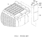
- a conventional heatsink water tank in accordance with the prior art shown in FIG. 1 comprises a plurality of water pipes 5.
- Each of the water pipes 5 includes a mouth portion 52 defining an opening 53, and a body portion 51 connected to the mouth portion 52.
- the mouth portion 52 includes two opposite extensions 521, a first curved portion 522 connecting the two extensions 521, and a second curved portion 523 connecting the two extensions 521 and located opposite to the first curved portion 522.
- the two extensions 521, the first curved portion 522 and the second curved portion 523 define the opening 53.
- the first curved portion 522 is formed by bending a sheet plate whose two sides are juxtaposed and connected by soldering to form the second curved portion 523.
- the mouth portion 52 is flared, so that the first curved portion 522 of the mouth portion 52 has a thickness smaller than that of the second curved portion 523 and the body portion 51.
- the first curved portion 522 has a smaller thickness and is subjected to a stress concentration, so that the first curved portion 522 easily forms cracks during a long period of time due to a direct hit of the water flow and an action of thermal expansion and contraction, thereby decreasing the lifetime of each of the water pipes 5.
- a reinforcing connecting assembly for water pipes, comprising a plurality of water pipes each of which includes a mouth portion defining an opening.
- the mouth portion includes two opposite extensions, a first curved portion connecting the two extensions, and a second curved portion connecting the two extensions and located opposite to the first curved portion.
- the two extensions, the first curved portion and the second curved portion define the opening.
- the reinforcing connecting assembly comprises a plurality of linking pieces and a connecting plate.
- Each of the linking pieces includes a connecting wall extending toward a first direction, and two opposite side walls connected with the connecting wall and extending toward a second direction perpendicular to the first direction.
- the connecting wall has a first surface abutting the first curved portion and a second surface opposite to the first surface.
- Each of the two side walls includes a reinforcing portion.
- the reinforcing portions of the two side walls are distant from each other and extend from two sides of the connecting wall toward a direction opposite to the first surface.
- the connecting plate connects the connecting wall of each of the linking pieces and adjoins the reinforcing portion.
- each of the two side walls further includes a guiding portion located opposite to the reinforcing portion and connected with the connecting wall, and an extending portion located between the reinforcing portion and the guiding portion and connected with the connecting wall.
- the guiding portions of the two side walls extend from two sides of the connecting wall toward a direction opposite to the first surface.
- the linking pieces and the connecting plate of the reinforcing connecting assembly are molded integrally.
- the connecting wall and the reinforcing portions of each of the linking pieces guide the water flow in the first curved portion of each of the water pipes and avoid the water flow from directly flushing the first curved portion, thereby preventing the first curved portion from forming cracks due to direct hit of the water flow, and thereby enhancing the lifetime of the water pipes.
- a reinforcing connecting assembly 1 in accordance with the preferred embodiment of the present invention is applied on a plurality of (preferably ten) water pipes 2 of a heatsink device (such as a heatsink water tank).
- a heatsink device such as a heatsink water tank.
- Each of the water pipes 2 includes a mouth portion 21 defining an opening 22, and a body portion 23 connected to the mouth portion 21.
- the mouth portion 21 includes two opposite extensions 211, a first curved portion 212 connecting the two extensions 211, and a second curved portion 213 connecting the two extensions 211 and located opposite to the first curved portion 212.
- the two extensions 211, the first curved portion 212 and the second curved portion 213 define the opening 22.
- the first curved portion 212 is formed by bending a sheet plate whose two sides are juxtaposed and connected to form the second curved portion 213.
- the reinforcing connecting assembly 1 comprises a plurality of (preferably five) linking pieces 11 and a connecting plate 12.
- Each of the linking pieces 11 includes a connecting wall 111 extending toward a first direction "D1", and two opposite side walls 112 connected with the connecting wall 111 and extending toward a second direction perpendicular to the first direction "D1".
- the connecting wall 111 has a first surface 113 and a second surface 114 opposite to the first surface 113.
- Each of the two side walls 112 includes a reinforcing portion 115 connected with the connecting wall 111, a guiding portion 116 located opposite to the reinforcing portion 115 and connected with the connecting wall 111, and an extending portion 117 located between the reinforcing portion 115 and the guiding portion 116 and connected with the connecting wall 111.
- the reinforcing portions 115 of the two side walls 112 are distant from each other and extend from two sides of the connecting wall 111 toward a direction opposite to the first surface 113.
- the guiding portions 116 of the two side walls 112 extend from two sides of the connecting wall 111 toward a direction opposite to the first surface 113.
- the connecting plate 12 connects the connecting wall 111 of each of the linking pieces 11 and adjoins the reinforcing portion 115.
- the linking pieces 11 and the connecting plate 12 of the reinforcing connecting assembly 1 are molded integrally.
- the reinforcing connecting assembly 1 is provided with a solder material.
- the connecting plate 12 of the reinforcing connecting assembly 1 is held by the operator, and each of the linking pieces 11 of the reinforcing connecting assembly 1 is inserted through the opening 22 into the mouth portion 21 of each of the water pipes 2 and extends to the body portion 23.
- the first surface 113 of the connecting wall 111 of each of the linking pieces 11 abuts the first curved portion 212 of the mouth portion 21 and the body portion 23, the reinforcing portions 115 of the two side walls 112 of each of the linking pieces 11 rest on the two extensions 211 of the mouth portion 21, while the extending portions 117 and the guiding portions 116 of the two side walls 112 of each of the linking pieces 11 rest on the body portion 23.
- the connecting plate 12 is placed outside of the opening 22 of each of the water pipes 2.
- the connecting wall 111 and the reinforcing portions 115 of the two side walls 112 of each of the linking pieces 11 guide the water flow in the first curved portion 212 of each of the water pipes 2 and avoid the water flow from directly flushing the first curved portion 212, thereby preventing the first curved portion 212 from being worn out or broken due to the direct hit of the water flow or the action of thermal expansion and contraction, and thereby enhancing the lifetime of the water pipes 2.
- the connecting wall 111, the guiding portions 116 and the extending portions 117 of each of the linking pieces 11 guide the water flow to the body portion 23 of each of the water pipes 2.
- the guiding portions 116 and the extending portions 117 of each of the linking pieces 11 are soldered to the body portion 23 of each of the water pipes 2, to enhance the stability of each of the linking pieces 11, thereby reinforcing each of the water pipes 2.
- the connecting plate 12 of the reinforcing connecting assembly 1 connects the linking pieces 11, and the linking pieces 11 are brazed to the water pipes 2, so that the water pipes 2 are secured by the linking pieces 11 and the connecting plate 12 of the reinforcing connecting assembly 1 and will not produce vibration.
- each of the linking pieces 11 guide the water flow in the first curved portion 212 of each of the water pipes 2 and avoid the water flow from directly flushing the first curved portion 212, thereby preventing the first curved portion 212 from forming cracks due to direct hit of the water flow, and thereby enhancing the lifetime of the water pipes 2.
- each of the linking pieces 11 reinforces each of the water pipes 2, without having to provide much material for reinforcing each of the water pipes 2, thereby saving the cost of material.
Landscapes
- Engineering & Computer Science (AREA)
- General Engineering & Computer Science (AREA)
- Mechanical Engineering (AREA)
- Physics & Mathematics (AREA)
- Thermal Sciences (AREA)
- Heat-Exchange Devices With Radiators And Conduit Assemblies (AREA)
- Details Of Fluid Heaters (AREA)
- Protection Of Pipes Against Damage, Friction, And Corrosion (AREA)
- Filling Or Discharging Of Gas Storage Vessels (AREA)
Abstract
Description
- The present invention relates to a connecting structure and, more particularly, to a reinforcing connecting assembly for water pipes of a heatsink device.
- A conventional heatsink water tank in accordance with the prior art shown in
FIG. 1 comprises a plurality ofwater pipes 5. Each of thewater pipes 5 includes amouth portion 52 defining anopening 53, and abody portion 51 connected to themouth portion 52. Themouth portion 52 includes twoopposite extensions 521, a firstcurved portion 522 connecting the twoextensions 521, and a secondcurved portion 523 connecting the twoextensions 521 and located opposite to the firstcurved portion 522. The twoextensions 521, the firstcurved portion 522 and the secondcurved portion 523 define theopening 53. In fabrication, the firstcurved portion 522 is formed by bending a sheet plate whose two sides are juxtaposed and connected by soldering to form the secondcurved portion 523. Then, themouth portion 52 is flared, so that the firstcurved portion 522 of themouth portion 52 has a thickness smaller than that of the secondcurved portion 523 and thebody portion 51. When the conventional heatsink water tank is mounted on a car to radiate and cool down the engine of the car, the water flows through theopening 53 into themouth portion 52 and thebody portion 51 of each of thewater pipes 5, so that the firstcurved portion 522 is flushed by the water flow constantly. At this time, the firstcurved portion 522 has a smaller thickness and is subjected to a stress concentration, so that the firstcurved portion 522 easily forms cracks during a long period of time due to a direct hit of the water flow and an action of thermal expansion and contraction, thereby decreasing the lifetime of each of thewater pipes 5. - In accordance with the present invention, there is provided a reinforcing connecting assembly for water pipes, comprising a plurality of water pipes each of which includes a mouth portion defining an opening. The mouth portion includes two opposite extensions, a first curved portion connecting the two extensions, and a second curved portion connecting the two extensions and located opposite to the first curved portion. The two extensions, the first curved portion and the second curved portion define the opening. The reinforcing connecting assembly comprises a plurality of linking pieces and a connecting plate. Each of the linking pieces includes a connecting wall extending toward a first direction, and two opposite side walls connected with the connecting wall and extending toward a second direction perpendicular to the first direction. The connecting wall has a first surface abutting the first curved portion and a second surface opposite to the first surface. Each of the two side walls includes a reinforcing portion. The reinforcing portions of the two side walls are distant from each other and extend from two sides of the connecting wall toward a direction opposite to the first surface. The connecting plate connects the connecting wall of each of the linking pieces and adjoins the reinforcing portion.
- Preferably, each of the two side walls further includes a guiding portion located opposite to the reinforcing portion and connected with the connecting wall, and an extending portion located between the reinforcing portion and the guiding portion and connected with the connecting wall. The guiding portions of the two side walls extend from two sides of the connecting wall toward a direction opposite to the first surface.
- Preferably, the linking pieces and the connecting plate of the reinforcing connecting assembly are molded integrally.
- According to the primary advantage of the present invention, the connecting wall and the reinforcing portions of each of the linking pieces guide the water flow in the first curved portion of each of the water pipes and avoid the water flow from directly flushing the first curved portion, thereby preventing the first curved portion from forming cracks due to direct hit of the water flow, and thereby enhancing the lifetime of the water pipes.
- Further benefits and advantages of the present invention will become apparent after a careful reading of the detailed description with appropriate reference to the accompanying drawings.
- In the drawings:
-
FIG. 1 is a perspective view of a conventional heatsink water tank in accordance with the prior art. -
FIG. 2 is a partially exploded perspective view showing a reinforcing connecting assembly and a plurality of water pipes in accordance with the preferred embodiment of the present invention. -
FIG. 3 is a partially exploded perspective view showing the reinforcing connecting assembly and the water pipes in accordance with the preferred embodiment of the present invention. -
FIG. 4 is a top view showing assembly of the reinforcing connecting assembly and the water pipes in accordance with the preferred embodiment of the present invention. -
FIG. 5 is a cross-sectional view of the reinforcing connecting assembly and the water pipes taken along line V-V as shown inFIG. 4 . -
FIG. 6 is a cross-sectional view of the reinforcing connecting assembly and the water pipes taken along line VI-VI as shown inFIG. 5 . - Referring to
FIGS. 2-6 , a reinforcing connectingassembly 1 in accordance with the preferred embodiment of the present invention is applied on a plurality of (preferably ten)water pipes 2 of a heatsink device (such as a heatsink water tank). - Each of the
water pipes 2 includes amouth portion 21 defining anopening 22, and abody portion 23 connected to themouth portion 21. Themouth portion 21 includes twoopposite extensions 211, a firstcurved portion 212 connecting the twoextensions 211, and a secondcurved portion 213 connecting the twoextensions 211 and located opposite to the firstcurved portion 212. The twoextensions 211, the firstcurved portion 212 and the secondcurved portion 213 define theopening 22. The firstcurved portion 212 is formed by bending a sheet plate whose two sides are juxtaposed and connected to form the secondcurved portion 213. - The reinforcing connecting
assembly 1 comprises a plurality of (preferably five) linkingpieces 11 and a connectingplate 12. Each of the linkingpieces 11 includes aconnecting wall 111 extending toward a first direction "D1", and twoopposite side walls 112 connected with theconnecting wall 111 and extending toward a second direction perpendicular to the first direction "D1". The connectingwall 111 has afirst surface 113 and asecond surface 114 opposite to thefirst surface 113. Each of the twoside walls 112 includes a reinforcingportion 115 connected with theconnecting wall 111, a guidingportion 116 located opposite to the reinforcingportion 115 and connected with theconnecting wall 111, and an extendingportion 117 located between the reinforcingportion 115 and the guidingportion 116 and connected with theconnecting wall 111. The reinforcingportions 115 of the twoside walls 112 are distant from each other and extend from two sides of the connectingwall 111 toward a direction opposite to thefirst surface 113. The guidingportions 116 of the twoside walls 112 extend from two sides of the connectingwall 111 toward a direction opposite to thefirst surface 113. The connectingplate 12 connects the connectingwall 111 of each of the linkingpieces 11 and adjoins the reinforcingportion 115. - In the preferred embodiment of the present invention, the linking
pieces 11 and the connectingplate 12 of the reinforcing connectingassembly 1 are molded integrally. - In assembly, referring to
FIGS. 4-6 with reference toFIGS. 2 and3 , the reinforcing connectingassembly 1 is provided with a solder material. The connectingplate 12 of the reinforcing connectingassembly 1 is held by the operator, and each of the linkingpieces 11 of the reinforcing connectingassembly 1 is inserted through theopening 22 into themouth portion 21 of each of thewater pipes 2 and extends to thebody portion 23. At this time, thefirst surface 113 of the connectingwall 111 of each of the linkingpieces 11 abuts the firstcurved portion 212 of themouth portion 21 and thebody portion 23, the reinforcingportions 115 of the twoside walls 112 of each of the linkingpieces 11 rest on the twoextensions 211 of themouth portion 21, while the extendingportions 117 and the guidingportions 116 of the twoside walls 112 of each of the linkingpieces 11 rest on thebody portion 23. Finally, the connectingplate 12 is placed outside of the opening 22 of each of thewater pipes 2. After the reinforcing connectingassembly 1 is assembled, the reinforcing connectingassembly 1 together with the heatsink device is placed into a brazier and heated, so that the reinforcing connectingassembly 1 is combined with thewater pipes 2 by brazing. When the heatsink device soldered with the reinforcing connectingassembly 1 is operated, theconnecting wall 111 and the reinforcingportions 115 of the twoside walls 112 of each of the linkingpieces 11 guide the water flow in the firstcurved portion 212 of each of thewater pipes 2 and avoid the water flow from directly flushing the firstcurved portion 212, thereby preventing the firstcurved portion 212 from being worn out or broken due to the direct hit of the water flow or the action of thermal expansion and contraction, and thereby enhancing the lifetime of thewater pipes 2. Then, the connectingwall 111, the guidingportions 116 and the extendingportions 117 of each of the linkingpieces 11 guide the water flow to thebody portion 23 of each of thewater pipes 2. At this time, the guidingportions 116 and the extendingportions 117 of each of the linkingpieces 11 are soldered to thebody portion 23 of each of thewater pipes 2, to enhance the stability of each of the linkingpieces 11, thereby reinforcing each of thewater pipes 2. In addition, the connectingplate 12 of the reinforcing connectingassembly 1 connects the linkingpieces 11, and the linkingpieces 11 are brazed to thewater pipes 2, so that thewater pipes 2 are secured by the linkingpieces 11 and the connectingplate 12 of the reinforcing connectingassembly 1 and will not produce vibration. - Accordingly, the connecting
wall 111 and the reinforcingportions 115 of each of the linkingpieces 11 guide the water flow in the firstcurved portion 212 of each of thewater pipes 2 and avoid the water flow from directly flushing the firstcurved portion 212, thereby preventing the firstcurved portion 212 from forming cracks due to direct hit of the water flow, and thereby enhancing the lifetime of thewater pipes 2. In addition, each of the linkingpieces 11 reinforces each of thewater pipes 2, without having to provide much material for reinforcing each of thewater pipes 2, thereby saving the cost of material. - Although the invention has been explained in relation to its preferred embodiment(s) as mentioned above, it is to be understood that many other possible modifications and variations can be made without departing from the scope of the present invention. It is, therefore, contemplated that the appended claim or claims will cover such modifications and variations that fall within the scope of the invention.
Claims (3)
- A reinforcing connecting assembly for water pipes, comprising:a plurality of water pipes (2) each of which includes a mouth portion (21) defining an opening (22);the mouth portion including two opposite extensions (211), a first curved portion (212) connecting the two extensions, and a second curved portion (213) connecting the two extensions and located opposite to the first curved portion;the two extensions, the first curved portion and the second curved portion defining the opening;wherein:the reinforcing connecting assembly (1) comprises a plurality of linking pieces (11) and a connecting plate (12);each of the linking pieces includes a connecting wall (111) extending toward a first direction (D1), and two opposite side walls (112) connected with the connecting wall and extending toward a second direction perpendicular to the first direction;the connecting wall has a first surface (113) abutting the first curved portion and a second surface (114) opposite to the first surface;each of the two side walls includes a reinforcing portion (115);the reinforcing portions of the two side walls are distant from each other and extend from two sides of the connecting wall toward a direction opposite to the first surface; andthe connecting plate connects the connecting wall of each of the linking pieces and adjoins the reinforcing portion.
- The reinforcing connecting assembly of claim 1, wherein:each of the two side walls further includes a guiding portion (116) located opposite to the reinforcing portion and connected with the connecting wall, and an extending portion (117) located between the reinforcing portion and the guiding portion and connected with the connecting wall; andthe guiding portions of the two side walls extend from two sides of the connecting wall toward a direction opposite to the first surface.
- The reinforcing connecting assembly of claim 1 or 2, wherein the linking pieces and the connecting plate of the reinforcing connecting assembly are molded integrally.
Applications Claiming Priority (1)
| Application Number | Priority Date | Filing Date | Title |
|---|---|---|---|
| TW106210900U TWM550369U (en) | 2017-07-25 | 2017-07-25 | Reinforced connection sheet set for water pipe |
Publications (2)
| Publication Number | Publication Date |
|---|---|
| EP3435019A1 true EP3435019A1 (en) | 2019-01-30 |
| EP3435019B1 EP3435019B1 (en) | 2019-12-25 |
Family
ID=61013625
Family Applications (1)
| Application Number | Title | Priority Date | Filing Date |
|---|---|---|---|
| EP18185268.2A Active EP3435019B1 (en) | 2017-07-25 | 2018-07-24 | Reinforcing connecting assembly for water pipes |
Country Status (4)
| Country | Link |
|---|---|
| US (1) | US10724668B2 (en) |
| EP (1) | EP3435019B1 (en) |
| CN (1) | CN208619224U (en) |
| TW (1) | TWM550369U (en) |
Citations (5)
| Publication number | Priority date | Publication date | Assignee | Title |
|---|---|---|---|---|
| US20070131404A1 (en) * | 2005-12-09 | 2007-06-14 | Denso Corporation | Heat exchanger |
| US20070144718A1 (en) * | 2003-11-20 | 2007-06-28 | Behr Gmbh & Co. Kg | Heat exchanger, especially charge air cooler for motor vehicles |
| JP2009204217A (en) * | 2008-02-27 | 2009-09-10 | T Rad Co Ltd | Tube connection structure of heat exchanger |
| TWM442687U (en) * | 2012-05-31 | 2012-12-01 | Cryomax Cooling System Corp | Water tank tube doubler |
| DE202014103206U1 (en) * | 2014-07-11 | 2015-10-14 | Autokühler GmbH & Co. KG | heat exchangers |
Family Cites Families (10)
| Publication number | Priority date | Publication date | Assignee | Title |
|---|---|---|---|---|
| US3190352A (en) * | 1962-08-23 | 1965-06-22 | Modine Mfg Co | Radiator tube protector |
| FR2696534B1 (en) * | 1992-10-02 | 1994-12-02 | Valeo Thermique Moteur Sa | Tube heat exchanger fitted with a flare. |
| US5626561A (en) * | 1995-06-07 | 1997-05-06 | Gore Hybrid Technologies, Inc. | Implantable containment apparatus for a therapeutical device and method for loading and reloading the device therein |
| DE102008007552B4 (en) * | 2008-02-05 | 2010-01-21 | Siemens Aktiengesellschaft | Device for increasing the bending stiffness of hoses |
| EP2326217A4 (en) * | 2008-09-08 | 2014-12-10 | Roho Inc | Inflatable cushion valve and attachment apparatus |
| DE102009005643B4 (en) * | 2009-01-22 | 2017-03-30 | Siemens Healthcare Gmbh | Device for increasing the bending stiffness of hoses |
| CN101995115B (en) * | 2009-08-07 | 2014-07-23 | 江森自控科技公司 | Multi-channel heat exchanger fins |
| WO2012018803A2 (en) * | 2010-08-03 | 2012-02-09 | Johnson Controls Technology Company | Multichannel tubes with deformable webs |
| EP3048985B1 (en) * | 2013-09-25 | 2019-04-24 | KCI Licensing, Inc. | Apparatuses for inline collection of a fluid specimen |
| US10337799B2 (en) * | 2013-11-25 | 2019-07-02 | Carrier Corporation | Dual duty microchannel heat exchanger |
-
2017
- 2017-07-25 TW TW106210900U patent/TWM550369U/en unknown
-
2018
- 2018-06-22 CN CN201820969310.8U patent/CN208619224U/en active Active
- 2018-07-24 EP EP18185268.2A patent/EP3435019B1/en active Active
- 2018-07-24 US US16/043,242 patent/US10724668B2/en active Active
Patent Citations (5)
| Publication number | Priority date | Publication date | Assignee | Title |
|---|---|---|---|---|
| US20070144718A1 (en) * | 2003-11-20 | 2007-06-28 | Behr Gmbh & Co. Kg | Heat exchanger, especially charge air cooler for motor vehicles |
| US20070131404A1 (en) * | 2005-12-09 | 2007-06-14 | Denso Corporation | Heat exchanger |
| JP2009204217A (en) * | 2008-02-27 | 2009-09-10 | T Rad Co Ltd | Tube connection structure of heat exchanger |
| TWM442687U (en) * | 2012-05-31 | 2012-12-01 | Cryomax Cooling System Corp | Water tank tube doubler |
| DE202014103206U1 (en) * | 2014-07-11 | 2015-10-14 | Autokühler GmbH & Co. KG | heat exchangers |
Also Published As
| Publication number | Publication date |
|---|---|
| US20190032834A1 (en) | 2019-01-31 |
| CN208619224U (en) | 2019-03-19 |
| EP3435019B1 (en) | 2019-12-25 |
| US10724668B2 (en) | 2020-07-28 |
| TWM550369U (en) | 2017-10-11 |
Similar Documents
| Publication | Publication Date | Title |
|---|---|---|
| CN108692587B (en) | Finned tube type heat exchanger | |
| KR20140001920A (en) | Latent heat exchanger and hot water supply device | |
| JP2001289590A5 (en) | ||
| EP2278253A2 (en) | Spacer, fixing structure and heat exchanger | |
| KR20200034582A (en) | Roasting smoking tool and heating element and mehtod of manufacturing the heating element | |
| JP6569293B2 (en) | Semiconductor device, metal member, and method of manufacturing semiconductor device | |
| CN101014822A (en) | Heat exchanger including flange | |
| US10724668B2 (en) | Reinforcing connecting assembly for water pipes | |
| JP2009204217A (en) | Tube connection structure of heat exchanger | |
| WO2007004457A1 (en) | Fin tube heat exchanger | |
| JP5661578B2 (en) | Manufacturing method of heat exchanger | |
| JP6181934B2 (en) | Terminal connection structure and manufacturing method thereof | |
| JP2005337573A (en) | Heat exchanger | |
| JP2006127873A (en) | Connector fixing metal fitting | |
| JP4239840B2 (en) | Mouth expansion jig for heat exchanger tubes | |
| JP2005308366A (en) | Heat exchanger | |
| KR20190143757A (en) | Heat Exchanger | |
| JP4626422B2 (en) | Finned tube heat exchanger | |
| EP2295914A2 (en) | Stacked pipe heat exchanger with guide members | |
| JP4398899B2 (en) | Heat exchanger exhaust duct | |
| JP5244536B2 (en) | Accessory mounting bracket and mounting method thereof | |
| JP4148963B2 (en) | Semiconductor laser device | |
| JP6104187B2 (en) | Board-mounted terminal device | |
| JP7106215B2 (en) | auger ice maker | |
| JP2005083647A (en) | Core structure of heat exchanger |
Legal Events
| Date | Code | Title | Description |
|---|---|---|---|
| PUAI | Public reference made under article 153(3) epc to a published international application that has entered the european phase |
Free format text: ORIGINAL CODE: 0009012 |
|
| STAA | Information on the status of an ep patent application or granted ep patent |
Free format text: STATUS: THE APPLICATION HAS BEEN PUBLISHED |
|
| AK | Designated contracting states |
Kind code of ref document: A1 Designated state(s): AL AT BE BG CH CY CZ DE DK EE ES FI FR GB GR HR HU IE IS IT LI LT LU LV MC MK MT NL NO PL PT RO RS SE SI SK SM TR |
|
| AX | Request for extension of the european patent |
Extension state: BA ME |
|
| STAA | Information on the status of an ep patent application or granted ep patent |
Free format text: STATUS: REQUEST FOR EXAMINATION WAS MADE |
|
| 17P | Request for examination filed |
Effective date: 20190201 |
|
| RBV | Designated contracting states (corrected) |
Designated state(s): AL AT BE BG CH CY CZ DE DK EE ES FI FR GB GR HR HU IE IS IT LI LT LU LV MC MK MT NL NO PL PT RO RS SE SI SK SM TR |
|
| STAA | Information on the status of an ep patent application or granted ep patent |
Free format text: STATUS: EXAMINATION IS IN PROGRESS |
|
| 17Q | First examination report despatched |
Effective date: 20190411 |
|
| GRAP | Despatch of communication of intention to grant a patent |
Free format text: ORIGINAL CODE: EPIDOSNIGR1 |
|
| STAA | Information on the status of an ep patent application or granted ep patent |
Free format text: STATUS: GRANT OF PATENT IS INTENDED |
|
| INTG | Intention to grant announced |
Effective date: 20190812 |
|
| GRAS | Grant fee paid |
Free format text: ORIGINAL CODE: EPIDOSNIGR3 |
|
| GRAA | (expected) grant |
Free format text: ORIGINAL CODE: 0009210 |
|
| STAA | Information on the status of an ep patent application or granted ep patent |
Free format text: STATUS: THE PATENT HAS BEEN GRANTED |
|
| AK | Designated contracting states |
Kind code of ref document: B1 Designated state(s): AL AT BE BG CH CY CZ DE DK EE ES FI FR GB GR HR HU IE IS IT LI LT LU LV MC MK MT NL NO PL PT RO RS SE SI SK SM TR |
|
| REG | Reference to a national code |
Ref country code: GB Ref legal event code: FG4D |
|
| REG | Reference to a national code |
Ref country code: CH Ref legal event code: EP |
|
| REG | Reference to a national code |
Ref country code: AT Ref legal event code: REF Ref document number: 1217577 Country of ref document: AT Kind code of ref document: T Effective date: 20200115 |
|
| REG | Reference to a national code |
Ref country code: DE Ref legal event code: R096 Ref document number: 602018001777 Country of ref document: DE |
|
| REG | Reference to a national code |
Ref country code: IE Ref legal event code: FG4D |
|
| REG | Reference to a national code |
Ref country code: NL Ref legal event code: FP |
|
| PG25 | Lapsed in a contracting state [announced via postgrant information from national office to epo] |
Ref country code: BG Free format text: LAPSE BECAUSE OF FAILURE TO SUBMIT A TRANSLATION OF THE DESCRIPTION OR TO PAY THE FEE WITHIN THE PRESCRIBED TIME-LIMIT Effective date: 20200325 Ref country code: FI Free format text: LAPSE BECAUSE OF FAILURE TO SUBMIT A TRANSLATION OF THE DESCRIPTION OR TO PAY THE FEE WITHIN THE PRESCRIBED TIME-LIMIT Effective date: 20191225 Ref country code: LT Free format text: LAPSE BECAUSE OF FAILURE TO SUBMIT A TRANSLATION OF THE DESCRIPTION OR TO PAY THE FEE WITHIN THE PRESCRIBED TIME-LIMIT Effective date: 20191225 Ref country code: LV Free format text: LAPSE BECAUSE OF FAILURE TO SUBMIT A TRANSLATION OF THE DESCRIPTION OR TO PAY THE FEE WITHIN THE PRESCRIBED TIME-LIMIT Effective date: 20191225 Ref country code: SE Free format text: LAPSE BECAUSE OF FAILURE TO SUBMIT A TRANSLATION OF THE DESCRIPTION OR TO PAY THE FEE WITHIN THE PRESCRIBED TIME-LIMIT Effective date: 20191225 Ref country code: NO Free format text: LAPSE BECAUSE OF FAILURE TO SUBMIT A TRANSLATION OF THE DESCRIPTION OR TO PAY THE FEE WITHIN THE PRESCRIBED TIME-LIMIT Effective date: 20200325 Ref country code: GR Free format text: LAPSE BECAUSE OF FAILURE TO SUBMIT A TRANSLATION OF THE DESCRIPTION OR TO PAY THE FEE WITHIN THE PRESCRIBED TIME-LIMIT Effective date: 20200326 |
|
| REG | Reference to a national code |
Ref country code: LT Ref legal event code: MG4D |
|
| PG25 | Lapsed in a contracting state [announced via postgrant information from national office to epo] |
Ref country code: RS Free format text: LAPSE BECAUSE OF FAILURE TO SUBMIT A TRANSLATION OF THE DESCRIPTION OR TO PAY THE FEE WITHIN THE PRESCRIBED TIME-LIMIT Effective date: 20191225 Ref country code: HR Free format text: LAPSE BECAUSE OF FAILURE TO SUBMIT A TRANSLATION OF THE DESCRIPTION OR TO PAY THE FEE WITHIN THE PRESCRIBED TIME-LIMIT Effective date: 20191225 |
|
| PG25 | Lapsed in a contracting state [announced via postgrant information from national office to epo] |
Ref country code: AL Free format text: LAPSE BECAUSE OF FAILURE TO SUBMIT A TRANSLATION OF THE DESCRIPTION OR TO PAY THE FEE WITHIN THE PRESCRIBED TIME-LIMIT Effective date: 20191225 |
|
| PG25 | Lapsed in a contracting state [announced via postgrant information from national office to epo] |
Ref country code: EE Free format text: LAPSE BECAUSE OF FAILURE TO SUBMIT A TRANSLATION OF THE DESCRIPTION OR TO PAY THE FEE WITHIN THE PRESCRIBED TIME-LIMIT Effective date: 20191225 Ref country code: RO Free format text: LAPSE BECAUSE OF FAILURE TO SUBMIT A TRANSLATION OF THE DESCRIPTION OR TO PAY THE FEE WITHIN THE PRESCRIBED TIME-LIMIT Effective date: 20191225 Ref country code: CZ Free format text: LAPSE BECAUSE OF FAILURE TO SUBMIT A TRANSLATION OF THE DESCRIPTION OR TO PAY THE FEE WITHIN THE PRESCRIBED TIME-LIMIT Effective date: 20191225 Ref country code: PT Free format text: LAPSE BECAUSE OF FAILURE TO SUBMIT A TRANSLATION OF THE DESCRIPTION OR TO PAY THE FEE WITHIN THE PRESCRIBED TIME-LIMIT Effective date: 20200520 |
|
| PG25 | Lapsed in a contracting state [announced via postgrant information from national office to epo] |
Ref country code: SM Free format text: LAPSE BECAUSE OF FAILURE TO SUBMIT A TRANSLATION OF THE DESCRIPTION OR TO PAY THE FEE WITHIN THE PRESCRIBED TIME-LIMIT Effective date: 20191225 Ref country code: IS Free format text: LAPSE BECAUSE OF FAILURE TO SUBMIT A TRANSLATION OF THE DESCRIPTION OR TO PAY THE FEE WITHIN THE PRESCRIBED TIME-LIMIT Effective date: 20200425 Ref country code: SK Free format text: LAPSE BECAUSE OF FAILURE TO SUBMIT A TRANSLATION OF THE DESCRIPTION OR TO PAY THE FEE WITHIN THE PRESCRIBED TIME-LIMIT Effective date: 20191225 |
|
| REG | Reference to a national code |
Ref country code: DE Ref legal event code: R097 Ref document number: 602018001777 Country of ref document: DE |
|
| PG25 | Lapsed in a contracting state [announced via postgrant information from national office to epo] |
Ref country code: DK Free format text: LAPSE BECAUSE OF FAILURE TO SUBMIT A TRANSLATION OF THE DESCRIPTION OR TO PAY THE FEE WITHIN THE PRESCRIBED TIME-LIMIT Effective date: 20191225 Ref country code: ES Free format text: LAPSE BECAUSE OF FAILURE TO SUBMIT A TRANSLATION OF THE DESCRIPTION OR TO PAY THE FEE WITHIN THE PRESCRIBED TIME-LIMIT Effective date: 20191225 |
|
| PLBE | No opposition filed within time limit |
Free format text: ORIGINAL CODE: 0009261 |
|
| STAA | Information on the status of an ep patent application or granted ep patent |
Free format text: STATUS: NO OPPOSITION FILED WITHIN TIME LIMIT |
|
| REG | Reference to a national code |
Ref country code: AT Ref legal event code: MK05 Ref document number: 1217577 Country of ref document: AT Kind code of ref document: T Effective date: 20191225 |
|
| PG25 | Lapsed in a contracting state [announced via postgrant information from national office to epo] |
Ref country code: SI Free format text: LAPSE BECAUSE OF FAILURE TO SUBMIT A TRANSLATION OF THE DESCRIPTION OR TO PAY THE FEE WITHIN THE PRESCRIBED TIME-LIMIT Effective date: 20191225 |
|
| 26N | No opposition filed |
Effective date: 20200928 |
|
| PG25 | Lapsed in a contracting state [announced via postgrant information from national office to epo] |
Ref country code: AT Free format text: LAPSE BECAUSE OF FAILURE TO SUBMIT A TRANSLATION OF THE DESCRIPTION OR TO PAY THE FEE WITHIN THE PRESCRIBED TIME-LIMIT Effective date: 20191225 Ref country code: IT Free format text: LAPSE BECAUSE OF FAILURE TO SUBMIT A TRANSLATION OF THE DESCRIPTION OR TO PAY THE FEE WITHIN THE PRESCRIBED TIME-LIMIT Effective date: 20191225 |
|
| PG25 | Lapsed in a contracting state [announced via postgrant information from national office to epo] |
Ref country code: MC Free format text: LAPSE BECAUSE OF FAILURE TO SUBMIT A TRANSLATION OF THE DESCRIPTION OR TO PAY THE FEE WITHIN THE PRESCRIBED TIME-LIMIT Effective date: 20191225 Ref country code: PL Free format text: LAPSE BECAUSE OF FAILURE TO SUBMIT A TRANSLATION OF THE DESCRIPTION OR TO PAY THE FEE WITHIN THE PRESCRIBED TIME-LIMIT Effective date: 20191225 |
|
| REG | Reference to a national code |
Ref country code: BE Ref legal event code: MM Effective date: 20200731 |
|
| PG25 | Lapsed in a contracting state [announced via postgrant information from national office to epo] |
Ref country code: LU Free format text: LAPSE BECAUSE OF NON-PAYMENT OF DUE FEES Effective date: 20200724 Ref country code: FR Free format text: LAPSE BECAUSE OF NON-PAYMENT OF DUE FEES Effective date: 20200731 |
|
| PG25 | Lapsed in a contracting state [announced via postgrant information from national office to epo] |
Ref country code: BE Free format text: LAPSE BECAUSE OF NON-PAYMENT OF DUE FEES Effective date: 20200731 |
|
| PG25 | Lapsed in a contracting state [announced via postgrant information from national office to epo] |
Ref country code: IE Free format text: LAPSE BECAUSE OF NON-PAYMENT OF DUE FEES Effective date: 20200724 |
|
| REG | Reference to a national code |
Ref country code: CH Ref legal event code: PL |
|
| PG25 | Lapsed in a contracting state [announced via postgrant information from national office to epo] |
Ref country code: LI Free format text: LAPSE BECAUSE OF NON-PAYMENT OF DUE FEES Effective date: 20210731 Ref country code: CH Free format text: LAPSE BECAUSE OF NON-PAYMENT OF DUE FEES Effective date: 20210731 |
|
| PG25 | Lapsed in a contracting state [announced via postgrant information from national office to epo] |
Ref country code: TR Free format text: LAPSE BECAUSE OF FAILURE TO SUBMIT A TRANSLATION OF THE DESCRIPTION OR TO PAY THE FEE WITHIN THE PRESCRIBED TIME-LIMIT Effective date: 20191225 Ref country code: MT Free format text: LAPSE BECAUSE OF FAILURE TO SUBMIT A TRANSLATION OF THE DESCRIPTION OR TO PAY THE FEE WITHIN THE PRESCRIBED TIME-LIMIT Effective date: 20191225 Ref country code: CY Free format text: LAPSE BECAUSE OF FAILURE TO SUBMIT A TRANSLATION OF THE DESCRIPTION OR TO PAY THE FEE WITHIN THE PRESCRIBED TIME-LIMIT Effective date: 20191225 |
|
| PG25 | Lapsed in a contracting state [announced via postgrant information from national office to epo] |
Ref country code: MK Free format text: LAPSE BECAUSE OF FAILURE TO SUBMIT A TRANSLATION OF THE DESCRIPTION OR TO PAY THE FEE WITHIN THE PRESCRIBED TIME-LIMIT Effective date: 20191225 |
|
| GBPC | Gb: european patent ceased through non-payment of renewal fee |
Effective date: 20220724 |
|
| PG25 | Lapsed in a contracting state [announced via postgrant information from national office to epo] |
Ref country code: GB Free format text: LAPSE BECAUSE OF NON-PAYMENT OF DUE FEES Effective date: 20220724 |
|
| REG | Reference to a national code |
Ref country code: DE Ref legal event code: R082 Ref document number: 602018001777 Country of ref document: DE |
|
| PGFP | Annual fee paid to national office [announced via postgrant information from national office to epo] |
Ref country code: NL Payment date: 20250709 Year of fee payment: 8 |
|
| PGFP | Annual fee paid to national office [announced via postgrant information from national office to epo] |
Ref country code: DE Payment date: 20250717 Year of fee payment: 8 |