EP3434963B1 - Valve protection device for pressurized gas containers - Google Patents
Valve protection device for pressurized gas containers Download PDFInfo
- Publication number
- EP3434963B1 EP3434963B1 EP18178283.0A EP18178283A EP3434963B1 EP 3434963 B1 EP3434963 B1 EP 3434963B1 EP 18178283 A EP18178283 A EP 18178283A EP 3434963 B1 EP3434963 B1 EP 3434963B1
- Authority
- EP
- European Patent Office
- Prior art keywords
- section
- valve
- bores
- fastening
- central axis
- Prior art date
- Legal status (The legal status is an assumption and is not a legal conclusion. Google has not performed a legal analysis and makes no representation as to the accuracy of the status listed.)
- Active
Links
- 230000001681 protective effect Effects 0.000 claims description 14
- 239000002184 metal Substances 0.000 claims description 5
- 239000007789 gas Substances 0.000 description 20
- 239000000463 material Substances 0.000 description 7
- 229910000831 Steel Inorganic materials 0.000 description 2
- 238000005553 drilling Methods 0.000 description 2
- 238000000605 extraction Methods 0.000 description 2
- 238000009434 installation Methods 0.000 description 2
- 239000010959 steel Substances 0.000 description 2
- 239000003638 chemical reducing agent Substances 0.000 description 1
- 230000000295 complement effect Effects 0.000 description 1
- 238000010276 construction Methods 0.000 description 1
- 230000009993 protective function Effects 0.000 description 1
- 238000003466 welding Methods 0.000 description 1
Images

Classifications
-
- F—MECHANICAL ENGINEERING; LIGHTING; HEATING; WEAPONS; BLASTING
- F17—STORING OR DISTRIBUTING GASES OR LIQUIDS
- F17C—VESSELS FOR CONTAINING OR STORING COMPRESSED, LIQUEFIED OR SOLIDIFIED GASES; FIXED-CAPACITY GAS-HOLDERS; FILLING VESSELS WITH, OR DISCHARGING FROM VESSELS, COMPRESSED, LIQUEFIED, OR SOLIDIFIED GASES
- F17C13/00—Details of vessels or of the filling or discharging of vessels
- F17C13/04—Arrangement or mounting of valves
-
- F—MECHANICAL ENGINEERING; LIGHTING; HEATING; WEAPONS; BLASTING
- F17—STORING OR DISTRIBUTING GASES OR LIQUIDS
- F17C—VESSELS FOR CONTAINING OR STORING COMPRESSED, LIQUEFIED OR SOLIDIFIED GASES; FIXED-CAPACITY GAS-HOLDERS; FILLING VESSELS WITH, OR DISCHARGING FROM VESSELS, COMPRESSED, LIQUEFIED, OR SOLIDIFIED GASES
- F17C2205/00—Vessel construction, in particular mounting arrangements, attachments or identifications means
- F17C2205/03—Fluid connections, filters, valves, closure means or other attachments
- F17C2205/0302—Fittings, valves, filters, or components in connection with the gas storage device
- F17C2205/0308—Protective caps
Definitions
- the invention relates to a valve protection device for compressed gas cylinders, with a fastening section which is equipped with means for fastening to a neck thread of a compressed gas cylinder and has a central bore, and with a valve protection section which can be connected to the fastening section and which has a bottom side with a central bore for the passage of a cylinder valve and a protective structure fixedly connected to the bottom side with at least one access opening for operating the cylinder valve, wherein after the two sections are connected the central bores of the attachment section and the bottom side are arranged to form a common central axis.
- Compressed gas bottles in which gases are stored at a pressure of, for example, 200 to 300 bar, usually have a bottle neck into which a withdrawal valve (referred to here as bottle valve) is firmly screwed.
- the bottle neck is usually equipped with an external thread (referred to here as neck thread) onto which a valve protection device for protecting the bottle valve against impacts etc. can be screwed.
- a known valve protection device is, for example, a steel cap that protects the cylinder valve, in particular during transport of the compressed gas cylinder. If the cylinder valve should be accessible when the valve protection device is in place, the valve protection device is equipped with one or more access openings.
- valve protection device When screwing on a valve protection device, it is not possible to precisely define the angular position of the valve protection device, since it is screwed on to a greater or lesser extent and the beginning of the cut of the thread is not defined and there is therefore a clear residual uncertainty with regard to the angular position.
- the exact angular position is irrelevant for simple protective devices such as the steel cap mentioned.
- the angular position of the access opening must correspond to the connection of the cylinder valve, which sometimes has to be traded off at the expense of the strength of the screw connection of the valve protection device on the bottle neck. It can This can be remedied by providing the valve protection device with multiple and/or oversized access openings, but this compromises the stability and protective function of the valve protection device.
- the protection device In order to be able to set the angular position of the valve protection device as precisely as possible, a common technical solution is for the protection device to be made up of two sections divided vertically, which are placed on the side of the neck thread at a fastening section and fixed to one another by means of a clamping device.
- the disadvantage of such an arrangement however, consists in an increased assembly effort and in a mechanically weakened structure.
- valve protection device for gas cylinders that can be used universally is known, which consists of two sections that can be horizontally connected to one another. While the lower section, here called the fastening section, consists of an annular element with an internal thread, which is screwed onto the neck thread in the usual way, the upper section, here called the valve protection section, has one or more access openings for operating the cylinder valve and one with a central opening bottom side equipped for passage of the cylinder valve for connection with the fastening section. Furthermore, the mounting portion has a number of circumferentially equally spaced, vertically projecting ribs which cooperate with complementary projecting ribs on the underside of the bottom side of the valve protection section.
- the two sections are fixed against each other against rotation by the slats, at the same time a Numerous possible angular positions can be realized between the two sections.
- An axial fixation takes place by means of a counter nut, which is inserted from above into a circumferential groove of the valve protection section and screwed onto the neck thread.
- Counter nut and fastening section can be additionally secured by additional screw connections.
- the EP18178283 refers to a gas cylinder that has a collar at each axial end of the gas cylinder.
- the object of the present invention is therefore to create a securing element for cylinder valves for compressed gas cylinders that can be fixed in a plurality of angular positions relative to a longitudinal axis of the compressed gas cylinder and that is simple in construction and easy to assemble.
- the central bore of the attachment section has an internal thread for screwing onto the Neck thread on, or the attachment portion is equipped with a clamping device for attachment to the neck thread.
- the valve protection section is fastened to the fastening section, the interacting connection sections enabling an axially fixed connection, i.e. a connection that secures against tensile loads along the central axis.
- the central axis here is understood to be the central axis through the central bore of the fastening section and the central axis through the central bore of the bottom side of the valve protection section, which coincides after the two sections of the valve protection device have been connected.
- a non-rotatable connection (against rotation about the central axis of the two sections relative to each other) is achieved by making two or more connections between connecting means in the permitted angular positions.
- An additional clamping device for axial fixation is not required.
- At least the connecting means in one section are expediently arranged rotationally symmetrically around the central axis, so that the number of possible angular positions at which the two sections can be attached to one another according to the invention corresponds to the number of the respective rotational symmetry. There is thus a wide range of variation in the angular positions of the two sections relative to one another, and the access opening in the valve protection section can be adapted to the position of the cylinder valve.
- an advantageous embodiment of the invention provides that the number of connecting means is different, with either the number of connecting means in the fastening section being greater than the number of connecting means in the valve protection section or, conversely, the number of connecting means in the valve protection section being greater than the number of connecting means in the attachment section.
- a particularly advantageous embodiment of the invention is characterized in that the fastening section and the valve protection section are each equipped with a plurality of recesses arranged radially at equal distances from the central axis, the recesses of at least one section being arranged at equal angular distances and with the recesses of the other section correspond in such a way that during a rotation about the central axis against each other at least in two angular positions, a plurality of recesses of one section are aligned with a plurality of recesses of the other section and can be positively and firmly connected with fastening means.
- fastening means should generally be understood here to mean means with which an axial fixation of the two recesses can be produced, such as screws, spring bolts, protruding buttons, etc.
- Both the attachment section and the bottom side of the valve protection section are each equipped with a plurality of recesses in the form of bores.
- a number of bores in the fastening section and a number of bores in the bottom side are brought into an aligned position and fixed in each case by means of suitable fastening means, for example a screw connection.
- suitable fastening means for example a screw connection.
- the bores of a section can expediently be equipped with internal threads.
- the section with the greater number of bores which necessarily have to be arranged at equal angular intervals, determines the desired variability with regard to the angular positions at which a secure connection between the sections can be established.
- the bores of a section are preferably equipped with threads.
- the two parts are then connected in a particularly simple manner by passing a screw through the unthreaded bore and screwing it into the thread of the bore of the other section.
- another advantageous embodiment of the invention provides that the recesses in one section are locking grooves and the connecting means in the respective other section are several locking hooks that correspond to the locking grooves and are made of a material with limited flexibility.
- latching grooves arranged parallel to the central axis completely run through the outer wall of the fastening section; when the two sections are connected to one another, the latching hooks engage behind the entire fastening section in the area of the latching grooves and thus ensure that the two sections are fixed axially.
- a further preferred embodiment of the invention which can be used in addition to or instead of the above embodiments, is characterized in that the fastening section or the valve protection section is provided with a plurality of parallel and at the same radial distance from the central axis protruding bolt is equipped, which correspond with correspondingly arranged holes in the other section such that upon rotation about the central axis of the two sections against each other at least in two Angular positions, the bolts can be carried out through the bores and can then be secured axially against slipping out of the bores with securing elements.
- the bolts can be equipped with a thread onto which a nut is screwed, which secures the bolt against slipping out of the bore and thus creates an axial fixation, or the bolts can be equipped with a split pin hole and the axial Fixation takes place with a corresponding cotter pin.
- another advantageous embodiment of the invention provides a positioning aid for axial fixing.
- the positioning aid for example a protruding flange, the central axes of the central openings of the fastening section and the bottom side are brought into line before the two sections are connected.
- Preferred materials for the fastening section and/or the valve protection section are metal, plastic or a combination of these two materials.
- Metal ensures high stability of the valve protection device, while plastic results in a comparatively low weight.
- the two sections can be made of the same material or of different materials, for example the fastening section is made of metal and the valve protection section is made of plastic.
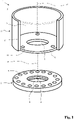
- the valve protection device 1 shown comprises two sections 2, 3 that can be connected to one another, namely a fastening section 2 for fastening to a compressed gas cylinder and a valve protection section 3 that can be connected to the fastening section 2.
- the attachment section 2 in the form of an annular disk in the exemplary embodiment has a central bore 4 with an internal thread 5 for screwing onto the neck thread of a compressed gas bottle.
- the size of the central bore 4 is determined by the neck thread and is, for example, 80 ⁇ 2.309 (Whitworth) in conventional compressed gas cylinders.
- the valve protection section 3 has a bottom side 6 which is equipped with a central bore 7 .
- the diameter of the central bore 7 is designed such that a cylinder valve (not shown here) can be passed through the bore 7 .
- the diameter of the central bore is therefore larger than the diameter of the central bore 4.
- the valve protection section 3 is connected to the fastening section 2 in the manner described in more detail below.
- a plurality of bores 10 are arranged in the fastening section 2 at equal angular spacings and the same radial spacing from the central axis 8 .
- bores 11 are arranged in the bottom side 6 of the valve protection section 3 at a radial distance from the bore 7, the radial distance of the bores 11 from the central axis 12 of the central bore 7 being the same as the radial distance of the bores 10 from the central axis 8.
- provided in the bottom side 6 three holes, but it can also be more or less.
- the number of bores 10 in the fastening section 2 can be the same as or different from the number of bores in the bottom side 6 . It is necessary that the angular distances of the bores 11 are dimensioned in such a way that when the two sections 2, 3 are connected to one another - described in more detail below - several bores 10 are present, which are aligned with one another with the bores 11 at a suitable angular position of the two sections 2, 3.
- the valve protection section 3 includes a protective structure 14 for protecting a cylinder valve, not shown here, and any additional installations connected to the cylinder valve (likewise not shown here), such as pressure reducers, line connections or display instruments.
- the protective structure 14 has at least one access opening 15 through which the cylinder valve and/or the aforesaid internals are made accessible to an operator.
- the protective structure 14 is a hollow cylinder reduced by the cut-out access opening 15 and made of an impact-resistant material, in particular metal or plastic, which is firmly connected to the bottom side 6, for example by welding.
- the configurations of the protective structure and access opening that are possible according to the invention are not limited to this, but rather depend on the requirements with regard to the type, size and arrangement of the built-in components and the required protection.
- the fastening section 2 is first screwed onto the neck valve of the gas cylinder.
- a cylinder valve such as a VIPR, is then screwed tightly into the neck of the gas cylinder.
- the bottom side 6 of the valve protection section 3 is then placed on the fastening section 2, the mounted cylinder valve being guided through the central bore 7 and the axes 8, 12 being brought into line.
- the angular position of the two sections 2 , 3 relative to one another is chosen such that the bores 11 in the bottom side 6 are aligned with the bores 10 or a corresponding number of bores 10 in the fastening section 2 .
- the sections are then connected to one another at the aligned bores 10, 11 by means of suitable connecting means, for example with a threaded rod (not shown here), which is guided through the two aligned bores 10, 11 and then fixed by means of nuts screwed onto both end faces.
- suitable connecting means for example with a threaded rod (not shown here), which is guided through the two aligned bores 10, 11 and then fixed by means of nuts screwed onto both end faces.
- the bores 10 or the bores 11 can be equipped with threads and the fastening takes place by means of Screws that pass through the bore 10, 11 of one section 2, 3 and are screwed into the threaded bore 11, 10 of the other section 3, 2.
- the angular position of the two sections 2, 3 relative to one another i.e. the angular position in a plane perpendicular to the axes 8, 10 can be selected according to the number of bores 10.
- An angular position is expediently selected which allows good accessibility of the cylinder valve and, if applicable, other built-in components connected to it through the access opening 15 .
- valve protection device 1′ shown only partially, with a fastening section 2′ and a valve protection section 3′ with an alternative possibility of connecting the sections 2′, 3′ to one another.
- the sections 2', 3' are similar to the sections 2, 3 from the exemplary embodiment according to FIG 1 constructed, ie the attachment portion 2' has a central bore with an internal thread for screwing onto the neck thread of a compressed gas cylinder, and the valve protection portion 3' has a bottom side 6' and a protective structure 14'.
- a plurality of latching grooves 18 are provided on the fastening section 2', which are arranged at equal angular intervals in the outer casing 19 of the fastening section 2'.
- a plurality of latching hooks 21 are arranged on the outer casing 20 of the bottom side 6', for example formed in one piece with the bottom side 6' or welded, glued or screwed to it.
- the latching hooks 21 are made of a material with limited flexibility, for example plastic, and their shape and size correspond to the latching grooves 19.
Landscapes
- Engineering & Computer Science (AREA)
- Mechanical Engineering (AREA)
- General Engineering & Computer Science (AREA)
- Filling Or Discharging Of Gas Storage Vessels (AREA)
- Supply Devices, Intensifiers, Converters, And Telemotors (AREA)
Description
Die Erfindung betrifft eine Ventilschutzeinrichtung für Druckgasflaschen, mit einem Befestigungsabschnitt, der mit Mitteln zum Befestigen an einem Halsgewinde einer Druckgasflasche ausgerüstet ist und eine zentrale Bohrung aufweist, und mit einem mit dem Befestigungsabschnitt verbindbaren Ventilschutzabschnitt, der eine Bodenseite mit einer zentralen Bohrung zur Durchführung eines Flaschenventils und einen fest mit der Bodenseite verbundenen Schutzaufbau mit wenigstens einer Zugangsöffnung zum Bedienen des Flaschenventils aufweist, wobei nach Verbinden der beiden Abschnitte die zentralen Bohrungen des Befestigungsabschnitts und der Bodenseite unter Ausbildung einer gemeinsamen Mittelachse angeordnet sind.The invention relates to a valve protection device for compressed gas cylinders, with a fastening section which is equipped with means for fastening to a neck thread of a compressed gas cylinder and has a central bore, and with a valve protection section which can be connected to the fastening section and which has a bottom side with a central bore for the passage of a cylinder valve and a protective structure fixedly connected to the bottom side with at least one access opening for operating the cylinder valve, wherein after the two sections are connected the central bores of the attachment section and the bottom side are arranged to form a common central axis.
Druckgasflaschen, in denen Gase bei einem Druck von beispielsweise 200 bis 300 bar gelagert werden, besitzen üblicherweise einen Flaschenhals, in den ein Entnahmeventil (hier Flaschenventil genannt) fest eingeschraubt ist. Der Flaschenhals ist zudem üblicherweise mit einem Außengewinde (hier Halsgewinde genannt) ausgerüstet, auf das eine Ventilschutzeinrichtung zum Schutz des Flaschenventils gegen Stöße etc. aufgeschraubt werden kann. Eine bekannte Ventilschutzeinrichtung ist beispielsweise eine Stahlkappe, die das Flaschenventil insbesondere während des Transports der Druckgasflasche schützt. Soll die Zugänglichkeit des Flaschenventils bei aufgesetzter Ventilschutzeinrichtung möglich sein, ist die Ventilschutzeinrichtung mit einer oder mehreren Zugangsöffnungen ausgerüstet.Compressed gas bottles, in which gases are stored at a pressure of, for example, 200 to 300 bar, usually have a bottle neck into which a withdrawal valve (referred to here as bottle valve) is firmly screwed. In addition, the bottle neck is usually equipped with an external thread (referred to here as neck thread) onto which a valve protection device for protecting the bottle valve against impacts etc. can be screwed. A known valve protection device is, for example, a steel cap that protects the cylinder valve, in particular during transport of the compressed gas cylinder. If the cylinder valve should be accessible when the valve protection device is in place, the valve protection device is equipped with one or more access openings.
Beim Aufschrauben einer Ventilschutzeinrichtung ist es nicht möglich, die Winkelposition der Ventilschutzvorrichtung genau zu definieren, da sie mehr oder weniger stark festgeschraubt werden sowie der Einschnittbeginn der Gewinde nicht definiert ist und somit eine deutliche Restunschärfe hinsichtlich der Winkelposition besteht. Die genaue Winkelposition spielt bei einfachen Schutzeinrichtungen wie beispielsweise der genannten Stahlkappe keine Rolle. Soll das Flaschenventil jedoch bei aufgesetzter Ventilschutzeinrichtung zugänglich sein, muss die Winkelposition der Zugangsöffnung mit dem Anschluss des Flaschenventils korrespondieren, was fallweise mit Abstrichen bei der Festigkeit der Schraubverbindung der Ventilschutzeinrichtung auf dem Flaschenhals erkauft werden muss. Dem kann zwar dadurch abgeholfen werden, dass die Ventilschutzeinrichtung mit mehreren und/oder übergroßen Zugangsöffnungen ausgestattet wird, dies beeinträchtigt jedoch die Stabilität und die Schutzfunktion der Ventilschutzeinrichtung.When screwing on a valve protection device, it is not possible to precisely define the angular position of the valve protection device, since it is screwed on to a greater or lesser extent and the beginning of the cut of the thread is not defined and there is therefore a clear residual uncertainty with regard to the angular position. The exact angular position is irrelevant for simple protective devices such as the steel cap mentioned. However, if the cylinder valve is to be accessible when the valve protection device is in place, the angular position of the access opening must correspond to the connection of the cylinder valve, which sometimes has to be traded off at the expense of the strength of the screw connection of the valve protection device on the bottle neck. It can This can be remedied by providing the valve protection device with multiple and/or oversized access openings, but this compromises the stability and protective function of the valve protection device.
In den letzten Jahren sind zudem zunehmend komplexere Ventilanordnungen zum Einsatz gelangt, sogenannte VIPR ("Valves with Integrated Pressure Regulator"), die ebenso komplexe Ventilschutzeinrichtungen verlangen. Bei derartigen Ventilanordnungen ist es erforderlich, die Schutzvorrichtung in genau definierter Winkelposition zu montieren, um die Zugänglichkeit aller Funktionalitäten, wie insbesondere Entnahmeanschlüsse, Reduzierventile, Anzeigearmaturen, etc. zu gewährleisten. Im Folgenden sollen Ventile mit und ohne derartige zusätzliche Funktionalitäten unter den Begriff des "Flaschenventils" subsumiert werden.In recent years, more and more complex valve arrangements have also come into use, so-called VIPRs ("Valves with Integrated Pressure Regulators"), which require equally complex valve protection devices. In the case of such valve arrangements, it is necessary to mount the protective device in a precisely defined angular position in order to ensure that all functionalities, such as extraction connections, reducing valves, display fittings, etc. in particular, are accessible. In the following, valves with and without such additional functionalities are subsumed under the term “cylinder valve”.
Um die Winkelposition der Ventilschutzeinrichtung möglichst genau einstellen zu können besteht eine gängige technische Lösung darin, dass die Schutzvorrichtung aus zwei Abschnitten in vertikaler Teilung aufgebaut ist, welche an einem Befestigungsabschnitt seitlich auf das Halsgewinde aufgesetzt und mittels einer Klemmvorrichtung miteinander fixiert werden. Der Nachteil einer solchen Anordnung besteht jedoch in einem erhöhtem Montageaufwand und in einer festigungsmechanisch geschwächten Struktur.In order to be able to set the angular position of the valve protection device as precisely as possible, a common technical solution is for the protection device to be made up of two sections divided vertically, which are placed on the side of the neck thread at a fastening section and fixed to one another by means of a clamping device. The disadvantage of such an arrangement, however, consists in an increased assembly effort and in a mechanically weakened structure.
Aus der
Diese Anordnung ermöglicht es, bei einer gleichbleibend stabilen Befestigung der Ventilschutzeinrichtung auf der Gasflasche die Winkelposition der Zugangsöffnungen der Schutzeinrichtung der Position des jeweiligen Entnahmeventils anzupassen. Allerdings ist die Schutzeinrichtung sehr aufwendig im Aufbau, und der Montageaufwand ist sehr hoch. Die
Aufgabe der vorliegenden Erfindung ist daher, ein Sicherungselement für Flaschenventile für Druckgasflaschen zu schaffen, das in einer eine Mehrzahl von Winkelpositionen gegenüber einer Längsachse der Druckgasflasche fixiert werden kann und das einfach im Aufbau und leicht zu montieren ist.The object of the present invention is therefore to create a securing element for cylinder valves for compressed gas cylinders that can be fixed in a plurality of angular positions relative to a longitudinal axis of the compressed gas cylinder and that is simple in construction and easy to assemble.
Gelöst ist diese Aufgabe durch die Vorrichtungen der Ansprüche 1 oder 4.This problem is solved by the devices of
Zum Befestigen am Halsgewinde der Druckgasflasche weist die zentrale Bohrung des Befestigungsabschnitts ein Innengewinde zum Aufschrauben auf das Halsgewinde auf, oder der Befestigungsabschnitt ist mit einer Klemmvorrichtung zum Befestigen am Halsgewinde ausgerüstet. Nach der Montage des Befestigungsabschnitts an der Druckgasflasche und dem anschließenden Einbau eines Flaschenventils erfolgt die Befestigung des Ventilschutzabschnitts am Befestigungsabschnitt, wobei die miteinander wirkenden Verbindungsabschnitte eine axialfeste, also gegen Zugbelastung längs der Mittelachse sichernde Verbindung ermöglichen. Als Mittelachse wird hier die - nach Verbinden der beiden Abschnitte der Ventilschutzeinrichtung übereinstimmende - Mittelachse durch die zentrale Bohrung des Befestigungsabschnitts und die Mittelachse durch die zentrale Bohrung der Bodenseite des Ventilschutzabschnitts verstanden. Zusätzlich wird eine drehfeste Verbindung (gegenüber einer Drehung um die Mittelachse der beiden Abschnitte gegeneinander) dadurch erreicht, dass in den erlaubten Winkelpositionen zwei oder mehr Verbindungen zwischen Verbindungsmitteln hergestellt werden. Eine zusätzliche Klemmvorrichtung zur axialen Fixierung ist nicht erforderlich.For attachment to the neck thread of the compressed gas bottle, the central bore of the attachment section has an internal thread for screwing onto the Neck thread on, or the attachment portion is equipped with a clamping device for attachment to the neck thread. After assembly of the fastening section on the compressed gas cylinder and the subsequent installation of a cylinder valve, the valve protection section is fastened to the fastening section, the interacting connection sections enabling an axially fixed connection, i.e. a connection that secures against tensile loads along the central axis. The central axis here is understood to be the central axis through the central bore of the fastening section and the central axis through the central bore of the bottom side of the valve protection section, which coincides after the two sections of the valve protection device have been connected. In addition, a non-rotatable connection (against rotation about the central axis of the two sections relative to each other) is achieved by making two or more connections between connecting means in the permitted angular positions. An additional clamping device for axial fixation is not required.
Zweckmäßigerweise sind zumindest die Verbindungsmittel in einem Abschnitt drehsymmetrisch um die Mittelachse angeordnet, sodass die Anzahl der möglichen Winkelpositionen, an denen die beiden Abschnitte erfindungsgemäß miteinander befestigt werden können, der Zähligkeit der jeweiligen Drehsymmetrie entspricht. Somit besteht eine breite Variationsmöglichkeit hinsichtlich der Winkelpositionen der beiden Abschnitte gegeneinander, und die Zugangsöffnung im Ventilschutzabschnitt kann der Position des Flaschenventils angepasst werden.At least the connecting means in one section are expediently arranged rotationally symmetrically around the central axis, so that the number of possible angular positions at which the two sections can be attached to one another according to the invention corresponds to the number of the respective rotational symmetry. There is thus a wide range of variation in the angular positions of the two sections relative to one another, and the access opening in the valve protection section can be adapted to the position of the cylinder valve.
Es ist im Übrigen nicht erforderlich, die gleiche Anzahl an Verbindungsmitteln in beiden Abschnitten vorzusehen. Eine vorteilhafte Ausgestaltung der Erfindung sieht vielmehr vor, dass die Zahl der Verbindungsmittel unterschiedlich ist, wobei entweder die Zahl der Verbindungsmittel im Befestigungsabschnitt größer ist als die Zahl der Verbindungsmittel im Ventilschutzabschnitt oder umgekehrt, die Zahl der Verbindungsmittel im Ventilschutzabschnitt größer ist als die Zahl der Verbindungsmittel im Befestigungsabschnitt. Um eine zuverlässige, axial- wie drehfeste Verbindung herzustellen sollten aber zumindest drei Verbindungsmittel vorhanden sein, an denen mit drei Verbindungsmitteln des anderen Abschnitts eine axial feste Verbindung hergestellt werden kann.Moreover, it is not necessary to provide the same number of connecting means in both sections. Rather, an advantageous embodiment of the invention provides that the number of connecting means is different, with either the number of connecting means in the fastening section being greater than the number of connecting means in the valve protection section or, conversely, the number of connecting means in the valve protection section being greater than the number of connecting means in the attachment section. However, in order to produce a reliable, axially and non-rotatably connected connection, there should be at least three connecting means on which an axially fixed connection can be produced with three connecting means of the other section.
Eine besonders vorteilhafte Ausführungsform der Erfindung ist dadurch gekennzeichnet, dass der Befestigungsabschnitt und der Ventilschutzabschnitt jeweils mit einer Mehrzahl von radial gleich beabstandet von der Mittelachse angeordneten Ausnehmungen ausgerüstet sind, wobei die Ausnehmungen zumindest eines Abschnitts in gleichmäßigen Winkelabständen angeordnet sind und mit den Ausnehmungen des anderen Abschnitts derart korrespondieren, dass bei einer Drehung um die Mittelachse gegeneinander zumindest in zwei Winkelpositionen eine Mehrzahl von Ausnehmungen des einen Abschnitts mit einer Mehrzahl von Ausnehmungen des anderen Abschnitts miteinander fluchten und mit Befestigungsmitteln formschlüssig-fest verbindbar sind.A particularly advantageous embodiment of the invention is characterized in that the fastening section and the valve protection section are each equipped with a plurality of recesses arranged radially at equal distances from the central axis, the recesses of at least one section being arranged at equal angular distances and with the recesses of the other section correspond in such a way that during a rotation about the central axis against each other at least in two angular positions, a plurality of recesses of one section are aligned with a plurality of recesses of the other section and can be positively and firmly connected with fastening means.
Als Ausnehmungen können hier nur Bohrungen gemäß Anspruch 1 verstanden werden, die in Befestigungsabschnitt oder Ventilschutzabschnitt (nachfolgend gemeinsam "Abschnitte" genannt) angeordnet sind. Als Befestigungsmittel sollen hier allgemein Mittel verstanden werden, mit denen eine axiale Fixierung der beiden Ausnehmungen hergestellt werden kann, wie beispielsweise Schrauben, Federbolzen, vorstehende Knöpfe, etc.Only bores according to
Sowohl der Befestigungsabschnitt als auch die Bodenseite des Ventilschutzabschnitts sind jeweils mit einer Mehrzahl von Ausnehmungen in Form von Bohrungen ausgerüstet. Zur Fixierung der beiden Abschnitte miteinander werden eine Anzahl von Bohrungen im Befestigungsabschnitt und eine Anzahl von Bohrungen in der Bodenseite in eine fluchtende Position gebracht und jeweils mittels geeigneter Befestigungsmittel, beispielsweise mittels einer Schraubverbindung, fixiert. Hierzu können die Bohrungen eines Abschnitts zweckmäßigerweise mit Innengewinden ausgestattet sein.Both the attachment section and the bottom side of the valve protection section are each equipped with a plurality of recesses in the form of bores. To fix the two sections together, a number of bores in the fastening section and a number of bores in the bottom side are brought into an aligned position and fixed in each case by means of suitable fastening means, for example a screw connection. For this purpose, the bores of a section can expediently be equipped with internal threads.
Auch bei dieser Ausgestaltung ist es im Rahmen der Erfindung keineswegs erforderlich, dass in den beiden Abschnitten jeweils die gleiche Anzahl an Bohrungen vorgesehen ist. Die Zahl der Bohrungen im Abschnitt mit der geringeren Anzahl an Bohrungen richtet sich nach den Erfordernissen bezüglich der Sicherheit und Stabilität der Verbindung. Zur Herstellung einer sicheren Verbindung sollten dabei in der Regel mindestens drei Bohrungen vorhanden sein, an denen die Abschnitte miteinander befestigt werden können, wobei diese Bohrungen in gleichen Winkelabständen vorliegen müssen.In this configuration, too, it is by no means necessary within the scope of the invention for the same number of bores to be provided in each of the two sections. The number of holes in the section with the lower number of holes depends on the requirements for security and stability of the connection. To make a safe Connection should usually be present at least three holes where the sections can be attached to each other, with these Holes must be in the same angular distances.
Der Abschnitt mit der größeren Anzahl der Bohrungen die notwendigerweise in gleichen Winkelabständen angeordnet sein müssen, bestimmt die dagegen die gewünschte Variabilität hinsichtlich der Winkelstellungen, bei denen eine sichere Verbindung zwischen den Abschnitten herstellbar ist. Je mehr Bohrungen dort vorhanden sind, desto mehr Winkelstellungen sind einstellbar.The section with the greater number of bores, which necessarily have to be arranged at equal angular intervals, determines the desired variability with regard to the angular positions at which a secure connection between the sections can be established. The more holes there are, the more angular positions can be set.
Bevorzugt sind die Bohrungen eines Abschnitts mit Gewinden ausgestattet.The bores of a section are preferably equipped with threads.
Die Verbindung der beiden Teile erfolgt dann in besonders einfacher Weise dadurch, dass eine Schraube durch die gewindefreie Bohrung hindurchgeführt und in das Gewinde der Bohrung des anderen Abschnitts eingeschraubt wird.The two parts are then connected in a particularly simple manner by passing a screw through the unthreaded bore and screwing it into the thread of the bore of the other section.
Alternativ zur vorgenannten Ausführungsform mit Bohrungen in beiden Abschnitten sieht eine andere vorteilhafte Ausgestaltung der Erfindung vor, dass als Ausnehmungen in einem Abschnitt Rastnuten und als Verbindungsmittel im jeweils anderen Abschnitt mehrere mit den Rastnuten korrespondierende, aus einem begrenzt flexiblen Material gefertigte Rasthaken vorgesehen sind. In einer besonders bevorzugten Ausführungsform durchziehen parallel zur Mittelachse angeordneten Rastnuten die Außenwand des Befestigungsabschnitts vollständig; beim Verbinden der beiden Abschnitte miteinander hintergreifen die Rasthaken den kompletten Befestigungsabschnitt im Bereich der Rastnuten und sorgen so für eine axiale Fixierung der beiden Abschnitte.As an alternative to the aforementioned embodiment with bores in both sections, another advantageous embodiment of the invention provides that the recesses in one section are locking grooves and the connecting means in the respective other section are several locking hooks that correspond to the locking grooves and are made of a material with limited flexibility. In a particularly preferred embodiment, latching grooves arranged parallel to the central axis completely run through the outer wall of the fastening section; when the two sections are connected to one another, the latching hooks engage behind the entire fastening section in the area of the latching grooves and thus ensure that the two sections are fixed axially.
Eine weitere bevorzugte Ausgestaltung der Erfindung, die ergänzend oder anstelle der vorstehenden Ausgestaltungen zum Einsatz kommen kann, ist dadurch gekennzeichnet, dass der Befestigungsabschnitt oder der Ventilschutzabschnitt mit einer Mehrzahl von parallel und in gleichem radialen Abstand zur Mittelachse vorstehenden Bolzen ausgerüstet ist, die mit entsprechend angeordneten Bohrungen im anderen Abschnitt derart korrespondieren, dass bei einer Drehung um die Mittelachse der beiden Abschnitte gegeneinander zumindest in zwei Winkelpositionen die Bolzen durch die Bohrungen durchführbar sind und anschließend mit Sicherungselementen axial gegen ein Herausrutschen aus den Bohrungen absicherbar sind. Zum Absichern der Bolzen können diese mit einem Gewinde ausgerüstet sein, auf das eine Mutter aufgeschraubt wird, die den Bolzen gegen ein Herausrutschen aus der Bohrung absichert und auf diese Weise eine axiale Fixierung schafft, oder die Bozen können mit einem Splintloch ausgerüstet sein und die axiale Fixierung erfolgt mit einem entsprechenden Splint.A further preferred embodiment of the invention, which can be used in addition to or instead of the above embodiments, is characterized in that the fastening section or the valve protection section is provided with a plurality of parallel and at the same radial distance from the central axis protruding bolt is equipped, which correspond with correspondingly arranged holes in the other section such that upon rotation about the central axis of the two sections against each other at least in two Angular positions, the bolts can be carried out through the bores and can then be secured axially against slipping out of the bores with securing elements. To secure the bolts, they can be equipped with a thread onto which a nut is screwed, which secures the bolt against slipping out of the bore and thus creates an axial fixation, or the bolts can be equipped with a split pin hole and the axial Fixation takes place with a corresponding cotter pin.
Um die beiden Abschnitte der Ventilschutzeinrichtung vor ihrer Verbindung miteinander in axialer Hinsicht gut positionieren zu können, ist in ein einer abermals vorteilhaften Ausgestaltung der Erfindung vorgesehen, dass eine Positionierhilfe zur axialen Fixierung vorgesehen ist. Mittels der Positionierhilfe, beispielsweise ein vorstehender Flansch, werden die Mittelachsen der zentralen Öffnungen von Befestigungsabschnitt und Bodenseite vor der Verbindung der beiden Abschnitte in Übereinstimmung gebracht.In order to be able to position the two sections of the valve protection device well in the axial direction before they are connected to one another, another advantageous embodiment of the invention provides a positioning aid for axial fixing. By means of the positioning aid, for example a protruding flange, the central axes of the central openings of the fastening section and the bottom side are brought into line before the two sections are connected.
Bevorzugte Materialien für den Befestigungsabschnitt und/oder den Ventilschutzabschnitt sind Metall, Kunststoff oder eine Kombinationen dieser beiden Werkstoffe. Metall sorgt für eine hohe Stabilität der Ventilschutzeinrichtung, Kunststoff führt zu einem vergleichsweise geringem Gewicht. Die beiden Abschnitte können dabei aus dem gleichen Material, oder aber aus verschiedenen Materialien bestehen, beispielsweise besteht der Befestigungsabschnitt aus Metall und der Ventilschutzabschnitt aus Kunststoff.Preferred materials for the fastening section and/or the valve protection section are metal, plastic or a combination of these two materials. Metal ensures high stability of the valve protection device, while plastic results in a comparatively low weight. The two sections can be made of the same material or of different materials, for example the fastening section is made of metal and the valve protection section is made of plastic.
Anhand der Zeichnung soll ein Ausführungsbeispiel der Erfindung näher erläutert werden. In schematischen Ansichten zeigen:
-
Fig. 1 : Eine erste Ausführungsform einer erfindungsgemäßen Ventilschutzeinrichtung in einer Schrägansicht, -
Fig. 2 : Eine andere Ausführungsform der Erfindung in einer Schrägansicht in einem Ausschnitt.
-
1 : A first embodiment of a valve protection device according to the invention in an oblique view, -
2 : Another embodiment of the invention in an oblique view in a section.
Die in
Der im Ausführungsbeispiel ringscheibenförmige Befestigungsabschnitt 2 weist eine zentrale Bohrung 4 mit einem Innengewinde 5 zum Aufschrauben auf das Halsgewinde einer Druckgasflasche auf. Die Größe der zentralen Bohrung 4 ist durch das Halsgewinde vorgegeben und beträgt beispielsweise bei üblichen Druckgasflaschen Ø 80 × 2,309 (Whitworth).The
Der Ventilschutzabschnitt 3 weist eine Bodenseite 6 auf, die mit einer zentralen Bohrung 7 ausgerüstet ist. Der Durchmesser der zentralen Bohrung 7 ist so ausgelegt, dass ein (hier nicht gezeigtes) Flaschenventil durch die Bohrung 7 hindurchgeführt werden kann. In der Regel ist der Durchmesser der zentralen Bohrung daher größer als der Durchmesser der zentralen Bohrung 4. An der Bodenseite 6 wird der Ventilschutzabschnitt 3 in der unten näher beschriebenen Weise mit dem Befestigungsabschnitt 2 verbunden.The
Radial beabstandet von einer Mittelachse 8 der zentralen Bohrung 4 sind im Befestigungsabschnitt 2 eine Mehrzahl an Bohrungen 10, im Ausführungsbeispiel sechzehn, in gleichmäßigen Winkelabständen und jeweils gleichem Radialabstand von der Mittelachse 8 angeordnet. Gleichzeitig sind in der Bodenseite 6 des Ventilschutzabschnitts 3 Bohrungen 11 radial beabstandet von der Bohrung 7 angeordnet, wobei der Radialabstand der Bohrungen 11 von der Mittelachse 12 der zentralen Bohrung 7 der gleiche ist wie der Radialabstand der Bohrungen 10 von der Mittelachse 8. Im Ausführungsbeispiel sind in der Bodenseite 6 drei Bohrungen vorgesehen, es können jedoch auch mehr oder weniger sein. Insbesondere kann die Anzahl der Bohrungen 10 im Befestigungsabschnitt 2 gleich oder ungleich der Anzahl der Bohrungen in der Bodenseite 6 sein. Es ist erforderlich, dass die Winkelabstände der Bohrungen 11 so bemessen sind, dass beim - unten näher beschriebenen - Verbinden der beiden Abschnitte 2, 3 miteinander im Befestigungsabschnitt 2 mehrere Bohrungen 10 vorhanden sind, die bei einer geeigneten Winkelstellung der beiden Abschnitte 2, 3 zueinander mit den Bohrungen 11 fluchten.Radially spaced from a
Weiterhin umfasst der Ventilschutzabschnitt 3 einen Schutzaufbau 14 zum Schutz eines hier nicht gezeigten Flaschenventils und gegebenenfalls zusätzlicher mit dem Flaschenventil verbundenen Einbauten (hier gleichfalls nicht gezeigt) wie beispielsweise Druckminderer, Leitungsanschlüsse oder Anzeigeinstrumente. Der Schutzaufbau 14 weist zumindest eine Zugangsöffnung 15 auf, durch die das Flaschenventil und/oder die genannten Einbauten für eine Bedienperson zugänglich gemacht werden. Im hier gezeigten Ausführungsbeispiel handelt es sich bei dem Schutzaufbau 14 um einen um die ausgeschnittene Zugangsöffnung 15 verminderten Hohlzylinder aus einem schlag- und stoßfestem Material, insbesondere aus Metall oder Kunststoff, der mit der Bodenseite 6 fest, beispielsweise durch Verschweißen, verbunden ist. Die erfindungsgemäß möglichen Ausgestaltungen von Schutzaufbau und Zugangsöffnung sind hierauf jedoch nicht beschränkt, sondern richten sich nach den Erfordernissen in Bezug auf Art, Größe und Anordnung der Einbauten und den geforderten Schutz.Furthermore, the
Zur Montage der Ventilschutzeinrichtung 1 auf eine Gasflasche wird zunächst der Befestigungsabschnitt 2 auf das Halsventil der Gasflasche aufgeschraubt. Im Anschluss daran wird ein Flaschenventil, beispielsweise ein VIPR, fest in den Flaschenhals der Gasflasche eingeschraubt. Sodann wird der Ventilschutzabschnitt 3 mit der Bodenseite 6 auf den Befestigungsabschnitt 2 aufgesetzt, wobei das aufmontierte Flaschenventil durch die zentrale Bohrung 7 geführt wird und die Achsen 8, 12 in Übereinstimmung gebracht werden. Die Winkelposition der beiden Abschnitte 2, 3 gegeneinander wird so gewählt, dass die Bohrungen 11 in der Bodenseite 6 mit den Bohrungen 10, bzw. einer entsprechenden Anzahl von Bohrungen 10, im Befestigungsabschnitt 2 fluchten. Anschließend werden die Abschnitte an den einander fluchtenden Bohrungen 10, 11 mittels geeigneter Verbindungsmittel miteinander verbunden, beispielsweise mit einer (hier nicht gezeigten) Gewindestange, die jeweils durch beide einander fluchtenden Bohrungen 10, 11 geführt und anschließend mittels an beiden Stirnseiten aufgeschraubten Muttern fixiert werden. Alternativ dazu können beispielsweise die Bohrungen 10 oder die Bohrungen 11 mit Gewinden ausgerüstet sein und die Befestigung erfolgt mittels Schrauben, die durch die Bohrung 10, 11 des einen Abschnitts 2, 3, geführt und in der mit Gewinde ausgerüsteten Bohrung 11, 10 des anderen Abschnitts 3, 2 eingeschraubt werden.To mount the
Aufgrund der jeweils gleichen Winkelabstände der Bohrungen 10 in der Bodenseite kann die Winkelposition der beiden Abschnitte 2, 3 gegeneinander, d.h. die Winkelposition in einer Ebene senkrecht zu den Achsen 8, 10, entsprechend der Anzahl der Bohrungen 10 gewählt werden. Zweckmäßigerweise wird eine Winkelposition gewählt, die eine gute Zugänglichkeit des Flaschenventils und ggf. sonstiger mit diesem verbundener Einbauten durch die Zugangsöffnung 15 erlaubt.Due to the same angular spacing of the
- 1, 1'1, 1'
- Ventilschutzeinrichtungvalve protection device
- 2, 2'2, 2'
- Befestigungsabschnittattachment section
- 3, 3'3, 3'
- Ventilschutzabschnittvalve protection section
- 4.4.
- Zentrale BohrungCentral hole
- 5.5.
- Innengewindeinner thread
- 6, 6'6, 6'
- Bodenseitebottom side
- 7.7.
- Zentrale BohrungCentral hole
- 8.8th.
- Mittelachsecentral axis
- 9.9.
- --
- 10.10
- Bohrungdrilling
- 11.11.
- Bohrungdrilling
- 12.12.
- Mittelachsecentral axis
- 13.13.
- --
- 14, 14'14, 14'
- Schutzaufbauprotective structure
- 15.15
- Zugangsöffnungaccess opening
- 16.16
- --
- 17.17
- --
- 18.18
- Rastnutlocking groove
- 19.19
- Außenmantelouter jacket
- 20.20
- Außenmantelouter jacket
- 21.21
- Rasthakenlatch hook
Claims (8)
- Valve-protection device for pressurized-gas bottles, having a fastening section (2, 2') which is provided with means (5) for fastening to a neck thread of a pressurized-gas bottle and has a central bore (4), and having a valve-protection section (3, 3') which can be connected to the fastening section (2, 2') and has a base side (6, 6') with a central bore (7) for leading through a bottle valve and has a protective structure (14, 14'), connected fixedly to the base side (6, 6'), with at least one access opening (15) for operation of the bottle valve, wherein, after connection of the two sections (2, 2'; 3, 3'), the central bores (4, 7) of the fastening section (2 2') and the base side (6, 6') are in a state arranged so as to form a common central axis (8, 12),
whereinthe fastening section (2, 2') and the valve-protection section (3, 3') are provided with mutually corresponding connecting means (10, 18; 11, 21) which are formed in such a way that an axially fixed connection can be produced between in each case one connecting means (10, 18; 11, 21) of the one section (2, 2'; 3, 3') and one connecting means (10, 18; 11, 21) of the other section (2, 2'; 3, 3'), wherein at least the connecting means (10, 18; 11, 21) of one section (2, 2'; 3, 3') are arranged rotationally symmetrically with respect to a rotation about the central axis (8, 12) and, if the two sections (2, 2'; 3, 3') are rotated about the central axis (8, 12) with respect to one another, there exist at least two angular positions in which multiple connecting means (10, 18; 11, 21) of the one section (2, 2'; 3, 3') can be connected to connecting means (10, 18; 11, 21) of the other section (2, 2'; 3, 3'),characterizedin that the fastening section (2, 2') and the valve-protection section (3, 3') are each provided with a plurality of bores (10, 11) which are arranged at equal radial distances from the central axis, wherein the bores (10, 11) of at least one section (2, 2'; 3, 3') are arranged at uniform angular intervals and correspond to the bores (10, 11) of the other section in such a way that, if rotated about the central axis (8, 12) with respect to one another, at least in two angular positions, a plurality of bores (11, 11) of the one section (2, 2'; 3, 3') and a plurality of bores (10, 11) of the other section (2, 2'; 3, 3') are aligned with one another and can be connected to one another fixedly in a form-fitting manner by fastening means. - Valve-protection device according to Claim 1, characterized in that the number of connecting means (10, 18; 11, 21) of the one section (2, 2'; 3, 3') is greater than the number of connecting means (10, 18; 11, 21) of the other section (2, 2'; 3, 3').
- Valve-protection device according to Claim 1, characterized in that the bores (10, 11) of one section (2, 2'; 3, 3') are provided with inner threads.
- Valve-protection device for pressurized-gas bottles, having a fastening section (2, 2') which is provided with means (5) for fastening to a neck thread of a pressurized-gas bottle and has a central bore (4), and having a valve-protection section (3, 3') which can be connected to the fastening section (2, 2') and has a base side (6, 6') with a central bore (7) for leading through a bottle valve and has a protective structure (14, 14'), connected fixedly to the base side (6, 6'), with at least one access opening (15) for operation of the bottle valve, wherein, after connection of the two sections (2, 2'; 3, 3'), the central bores (4, 7) of the fastening section (2 2') and the base side (6, 6') are in a state arranged so as to form a common central axis (8, 12),
whereinthe fastening section (2, 2') and the valve-protection section (3, 3') are provided with mutually corresponding connecting means (10, 18; 11, 21) which are formed in such a way that an axially fixed connection can be produced between in each case one connecting means (10, 18; 11, 21) of the one section (2, 2'; 3, 3') and one connecting means (10, 18; 11, 21) of the other section (2, 2'; 3, 3'), wherein at least the connecting means (10, 18; 11, 21) of one section (2, 2'; 3, 3') are arranged rotationally symmetrically with respect to a rotation about the central axis (8, 12) and, if the two sections (2, 2'; 3, 3') are rotated about the central axis (8, 12) with respect to one another, there exist at least two angular positions in which multiple connecting means (10, 18; 11, 21) of the one section (2, 2'; 3, 3') can be connected to connecting means (10, 18; 11, 21) of the other section (2, 2'; 3, 3'),characterizedin that the fastening section (2, 2') or the valve-protection section (3, 3') is provided with a plurality of latching grooves (18) which in each case are arranged at equal distances from a central axis (8, 12) of the valve protection arrangement (1, 1') and are arranged at uniform angular intervals radially with respect to the central axis (8, 12) and correspond to latching hooks (21) of the other section (2, 2'; 3, 3') in such a way that, if the two sections (2, 2'; 3, 3') are rotated about the central axis (8, 12) with respect to one another, at least in two angular positions, a plurality of the latching grooves (18) interacts with a plurality of the latching hooks (21) for the purpose of producing an axial connection. - Valve-protection device according to one of the preceding claims, characterized in that the fastening section (2, 2') or the valve-protection section (3, 3') is provided with a plurality of bolts which project parallel to the central axis (8, 12) and at equal radial distances therefrom and at uniform angular intervals and which correspond to correspondingly arranged bores (10, 11) in the in each case other section (2, 2'; 3, 3') in such a way that, if the two sections (2, 2'; 3, 3') are rotated about the central axis (8, 12) with respect to one another, at least in two angular positions, the bolts can be passed through a plurality of bores (10, 11), wherein the bolts can be secured axially against sliding-out from the bores (10, 11) by securing elements.
- Valve-protection device according to one of the preceding claims, characterized in that a positioning aid is provided for axial fixing of the two sections (2, 2'; 3, 3') with respect to one another.
- Valve-protection device according to one of the preceding claims, characterized in that the fastening section (2, 2') and/or the valve protection section (3, 3') are/is manufactured at least partially from metal.
- Valve-protection device according to one of the preceding claims, characterized in that the fastening section (2, 2') and/or the valve protection section (3, 3') are/is manufactured at least partially from plastic.
Applications Claiming Priority (1)
| Application Number | Priority Date | Filing Date | Title |
|---|---|---|---|
| DE102017007162.4A DE102017007162A1 (en) | 2017-07-27 | 2017-07-27 | Valve protection device for pressurized gas containers |
Publications (2)
| Publication Number | Publication Date |
|---|---|
| EP3434963A1 EP3434963A1 (en) | 2019-01-30 |
| EP3434963B1 true EP3434963B1 (en) | 2022-05-04 |
Family
ID=62778693
Family Applications (1)
| Application Number | Title | Priority Date | Filing Date |
|---|---|---|---|
| EP18178283.0A Active EP3434963B1 (en) | 2017-07-27 | 2018-06-18 | Valve protection device for pressurized gas containers |
Country Status (4)
| Country | Link |
|---|---|
| EP (1) | EP3434963B1 (en) |
| DE (1) | DE102017007162A1 (en) |
| ES (1) | ES2919952T3 (en) |
| PL (1) | PL3434963T3 (en) |
Families Citing this family (4)
| Publication number | Priority date | Publication date | Assignee | Title |
|---|---|---|---|---|
| USD930783S1 (en) | 2019-09-03 | 2021-09-14 | Amtrol Licensing, Inc. | Handle |
| US10982814B2 (en) | 2019-09-03 | 2021-04-20 | Amtrol Licensing Inc. | Handle assembly for a portable pressurized gas cylinder |
| US11585491B2 (en) * | 2020-08-06 | 2023-02-21 | Amtrol Licensing Inc. | Handle for a portable cylinder |
| US12129970B2 (en) | 2023-02-17 | 2024-10-29 | Amtrol Licensing Inc. | Handle for a portable cylinder |
Family Cites Families (4)
| Publication number | Priority date | Publication date | Assignee | Title |
|---|---|---|---|---|
| US5709252A (en) * | 1995-06-06 | 1998-01-20 | Progas, Inc. | Natural gas distribution system |
| FR3013101B1 (en) * | 2013-11-08 | 2015-11-06 | Rovip | UNIVERSAL PROTECTOR FOR GAS BOTTLE |
| GB2509229A (en) | 2013-11-19 | 2014-06-25 | Rolls Royce Plc | Gas turbine engine fan stand with hinged rotating frame |
| EP3193072B1 (en) * | 2016-01-12 | 2017-12-13 | Rovip | Universal protector for gas cylinder |
-
2017
- 2017-07-27 DE DE102017007162.4A patent/DE102017007162A1/en not_active Withdrawn
-
2018
- 2018-06-18 PL PL18178283.0T patent/PL3434963T3/en unknown
- 2018-06-18 ES ES18178283T patent/ES2919952T3/en active Active
- 2018-06-18 EP EP18178283.0A patent/EP3434963B1/en active Active
Also Published As
| Publication number | Publication date |
|---|---|
| PL3434963T3 (en) | 2022-08-08 |
| DE102017007162A1 (en) | 2019-01-31 |
| ES2919952T3 (en) | 2022-07-29 |
| EP3434963A1 (en) | 2019-01-30 |
Similar Documents
| Publication | Publication Date | Title |
|---|---|---|
| EP3434963B1 (en) | Valve protection device for pressurized gas containers | |
| DE69902944T2 (en) | FASTENING DEVICE FOR FAST APPLICATION DISCONNECTING A COMPONENT TO A BZW. FROM A SURFACE | |
| EP3032093B1 (en) | Fastening device for fastening a rotor blade to a rotor hub of a wind energy plant | |
| DE60219774T2 (en) | VALVE LOCKS | |
| EP3867465B1 (en) | Device for fixing a door or window handle | |
| DE2727949A1 (en) | SECURITY SEAL DEVICE, IN PARTICULAR FOR USE IN ELECTRICAL SUPPLY METERS | |
| DE10056341C2 (en) | Device for lashing containers | |
| DE4200096A1 (en) | DEVICE FOR CLOSING AN OPENING IN A FAIRING | |
| DE2615322C2 (en) | Fastening device for door plates or door rosettes | |
| DE102015007288B4 (en) | Customs seal | |
| DE4225743C2 (en) | Protective cap made of plastic | |
| EP0729540B1 (en) | Door or window hinge | |
| EP2530223B1 (en) | Safety fence | |
| EP3574813B1 (en) | Hinge for a toilet seat set | |
| DE2945540A1 (en) | Lockable closure for oil tank filler pipes - has sleeve secured by locking pins and opening for lock plug carrying outer thread for socket cap | |
| DE202020103617U1 (en) | Anti-twist device | |
| DE10050024C2 (en) | valve assembly | |
| DE102018122701A1 (en) | Holder system for attaching a container to a vehicle | |
| DE2248724A1 (en) | DOORBAND | |
| DE19962595A1 (en) | Blind rivet comprises sleeve with internal thread and bolt which fits into this, compression zone in center of sleeve being compressed when bolt is tightened to form collar which holds rivet in place | |
| EP0387634A1 (en) | Armature with stroke limitation | |
| EP0861955B1 (en) | Lockable window handle | |
| DE8527958U1 (en) | Door fitting | |
| DE19703880C2 (en) | Locking device | |
| AT405561B (en) | PANEL FASTENING ELEMENT |
Legal Events
| Date | Code | Title | Description |
|---|---|---|---|
| PUAI | Public reference made under article 153(3) epc to a published international application that has entered the european phase |
Free format text: ORIGINAL CODE: 0009012 |
|
| STAA | Information on the status of an ep patent application or granted ep patent |
Free format text: STATUS: THE APPLICATION HAS BEEN PUBLISHED |
|
| AK | Designated contracting states |
Kind code of ref document: A1 Designated state(s): AL AT BE BG CH CY CZ DE DK EE ES FI FR GB GR HR HU IE IS IT LI LT LU LV MC MK MT NL NO PL PT RO RS SE SI SK SM TR |
|
| AX | Request for extension of the european patent |
Extension state: BA ME |
|
| STAA | Information on the status of an ep patent application or granted ep patent |
Free format text: STATUS: REQUEST FOR EXAMINATION WAS MADE |
|
| 17P | Request for examination filed |
Effective date: 20190730 |
|
| RAX | Requested extension states of the european patent have changed |
Extension state: BA Payment date: 20190730 Extension state: ME Payment date: 20190730 |
|
| RBV | Designated contracting states (corrected) |
Designated state(s): AL AT BE BG CH CY CZ DE DK EE ES FI FR GB GR HR HU IE IS IT LI LT LU LV MC MK MT NL NO PL PT RO RS SE SI SK SM TR |
|
| GRAP | Despatch of communication of intention to grant a patent |
Free format text: ORIGINAL CODE: EPIDOSNIGR1 |
|
| STAA | Information on the status of an ep patent application or granted ep patent |
Free format text: STATUS: GRANT OF PATENT IS INTENDED |
|
| INTG | Intention to grant announced |
Effective date: 20211202 |
|
| GRAS | Grant fee paid |
Free format text: ORIGINAL CODE: EPIDOSNIGR3 |
|
| GRAA | (expected) grant |
Free format text: ORIGINAL CODE: 0009210 |
|
| STAA | Information on the status of an ep patent application or granted ep patent |
Free format text: STATUS: THE PATENT HAS BEEN GRANTED |
|
| AK | Designated contracting states |
Kind code of ref document: B1 Designated state(s): AL AT BE BG CH CY CZ DE DK EE ES FI FR GB GR HR HU IE IS IT LI LT LU LV MC MK MT NL NO PL PT RO RS SE SI SK SM TR |
|
| REG | Reference to a national code |
Ref country code: GB Ref legal event code: FG4D Free format text: NOT ENGLISH |
|
| REG | Reference to a national code |
Ref country code: CH Ref legal event code: EP |
|
| REG | Reference to a national code |
Ref country code: AT Ref legal event code: REF Ref document number: 1489400 Country of ref document: AT Kind code of ref document: T Effective date: 20220515 |
|
| REG | Reference to a national code |
Ref country code: DE Ref legal event code: R096 Ref document number: 502018009542 Country of ref document: DE |
|
| REG | Reference to a national code |
Ref country code: IE Ref legal event code: FG4D Free format text: LANGUAGE OF EP DOCUMENT: GERMAN |
|
| REG | Reference to a national code |
Ref country code: ES Ref legal event code: FG2A Ref document number: 2919952 Country of ref document: ES Kind code of ref document: T3 Effective date: 20220729 |
|
| REG | Reference to a national code |
Ref country code: LT Ref legal event code: MG9D |
|
| REG | Reference to a national code |
Ref country code: NL Ref legal event code: MP Effective date: 20220504 |
|
| PG25 | Lapsed in a contracting state [announced via postgrant information from national office to epo] |
Ref country code: SE Free format text: LAPSE BECAUSE OF FAILURE TO SUBMIT A TRANSLATION OF THE DESCRIPTION OR TO PAY THE FEE WITHIN THE PRESCRIBED TIME-LIMIT Effective date: 20220504 Ref country code: PT Free format text: LAPSE BECAUSE OF FAILURE TO SUBMIT A TRANSLATION OF THE DESCRIPTION OR TO PAY THE FEE WITHIN THE PRESCRIBED TIME-LIMIT Effective date: 20220905 Ref country code: NO Free format text: LAPSE BECAUSE OF FAILURE TO SUBMIT A TRANSLATION OF THE DESCRIPTION OR TO PAY THE FEE WITHIN THE PRESCRIBED TIME-LIMIT Effective date: 20220804 Ref country code: NL Free format text: LAPSE BECAUSE OF FAILURE TO SUBMIT A TRANSLATION OF THE DESCRIPTION OR TO PAY THE FEE WITHIN THE PRESCRIBED TIME-LIMIT Effective date: 20220504 Ref country code: LT Free format text: LAPSE BECAUSE OF FAILURE TO SUBMIT A TRANSLATION OF THE DESCRIPTION OR TO PAY THE FEE WITHIN THE PRESCRIBED TIME-LIMIT Effective date: 20220504 Ref country code: HR Free format text: LAPSE BECAUSE OF FAILURE TO SUBMIT A TRANSLATION OF THE DESCRIPTION OR TO PAY THE FEE WITHIN THE PRESCRIBED TIME-LIMIT Effective date: 20220504 Ref country code: GR Free format text: LAPSE BECAUSE OF FAILURE TO SUBMIT A TRANSLATION OF THE DESCRIPTION OR TO PAY THE FEE WITHIN THE PRESCRIBED TIME-LIMIT Effective date: 20220805 Ref country code: FI Free format text: LAPSE BECAUSE OF FAILURE TO SUBMIT A TRANSLATION OF THE DESCRIPTION OR TO PAY THE FEE WITHIN THE PRESCRIBED TIME-LIMIT Effective date: 20220504 Ref country code: BG Free format text: LAPSE BECAUSE OF FAILURE TO SUBMIT A TRANSLATION OF THE DESCRIPTION OR TO PAY THE FEE WITHIN THE PRESCRIBED TIME-LIMIT Effective date: 20220804 |
|
| PG25 | Lapsed in a contracting state [announced via postgrant information from national office to epo] |
Ref country code: RS Free format text: LAPSE BECAUSE OF FAILURE TO SUBMIT A TRANSLATION OF THE DESCRIPTION OR TO PAY THE FEE WITHIN THE PRESCRIBED TIME-LIMIT Effective date: 20220504 Ref country code: LV Free format text: LAPSE BECAUSE OF FAILURE TO SUBMIT A TRANSLATION OF THE DESCRIPTION OR TO PAY THE FEE WITHIN THE PRESCRIBED TIME-LIMIT Effective date: 20220504 Ref country code: IS Free format text: LAPSE BECAUSE OF FAILURE TO SUBMIT A TRANSLATION OF THE DESCRIPTION OR TO PAY THE FEE WITHIN THE PRESCRIBED TIME-LIMIT Effective date: 20220904 |
|
| PG25 | Lapsed in a contracting state [announced via postgrant information from national office to epo] |
Ref country code: SM Free format text: LAPSE BECAUSE OF FAILURE TO SUBMIT A TRANSLATION OF THE DESCRIPTION OR TO PAY THE FEE WITHIN THE PRESCRIBED TIME-LIMIT Effective date: 20220504 Ref country code: SK Free format text: LAPSE BECAUSE OF FAILURE TO SUBMIT A TRANSLATION OF THE DESCRIPTION OR TO PAY THE FEE WITHIN THE PRESCRIBED TIME-LIMIT Effective date: 20220504 Ref country code: RO Free format text: LAPSE BECAUSE OF FAILURE TO SUBMIT A TRANSLATION OF THE DESCRIPTION OR TO PAY THE FEE WITHIN THE PRESCRIBED TIME-LIMIT Effective date: 20220504 Ref country code: EE Free format text: LAPSE BECAUSE OF FAILURE TO SUBMIT A TRANSLATION OF THE DESCRIPTION OR TO PAY THE FEE WITHIN THE PRESCRIBED TIME-LIMIT Effective date: 20220504 Ref country code: DK Free format text: LAPSE BECAUSE OF FAILURE TO SUBMIT A TRANSLATION OF THE DESCRIPTION OR TO PAY THE FEE WITHIN THE PRESCRIBED TIME-LIMIT Effective date: 20220504 Ref country code: CZ Free format text: LAPSE BECAUSE OF FAILURE TO SUBMIT A TRANSLATION OF THE DESCRIPTION OR TO PAY THE FEE WITHIN THE PRESCRIBED TIME-LIMIT Effective date: 20220504 |
|
| REG | Reference to a national code |
Ref country code: CH Ref legal event code: PL |
|
| REG | Reference to a national code |
Ref country code: DE Ref legal event code: R097 Ref document number: 502018009542 Country of ref document: DE |
|
| REG | Reference to a national code |
Ref country code: BE Ref legal event code: MM Effective date: 20220630 |
|
| PG25 | Lapsed in a contracting state [announced via postgrant information from national office to epo] |
Ref country code: MC Free format text: LAPSE BECAUSE OF FAILURE TO SUBMIT A TRANSLATION OF THE DESCRIPTION OR TO PAY THE FEE WITHIN THE PRESCRIBED TIME-LIMIT Effective date: 20220504 |
|
| PLBE | No opposition filed within time limit |
Free format text: ORIGINAL CODE: 0009261 |
|
| STAA | Information on the status of an ep patent application or granted ep patent |
Free format text: STATUS: NO OPPOSITION FILED WITHIN TIME LIMIT |
|
| PG25 | Lapsed in a contracting state [announced via postgrant information from national office to epo] |
Ref country code: AL Free format text: LAPSE BECAUSE OF FAILURE TO SUBMIT A TRANSLATION OF THE DESCRIPTION OR TO PAY THE FEE WITHIN THE PRESCRIBED TIME-LIMIT Effective date: 20220504 |
|
| 26N | No opposition filed |
Effective date: 20230207 |
|
| GBPC | Gb: european patent ceased through non-payment of renewal fee |
Effective date: 20220804 |
|
| PG25 | Lapsed in a contracting state [announced via postgrant information from national office to epo] |
Ref country code: LU Free format text: LAPSE BECAUSE OF NON-PAYMENT OF DUE FEES Effective date: 20220618 Ref country code: LI Free format text: LAPSE BECAUSE OF NON-PAYMENT OF DUE FEES Effective date: 20220630 Ref country code: IE Free format text: LAPSE BECAUSE OF NON-PAYMENT OF DUE FEES Effective date: 20220618 Ref country code: CH Free format text: LAPSE BECAUSE OF NON-PAYMENT OF DUE FEES Effective date: 20220630 |
|
| PG25 | Lapsed in a contracting state [announced via postgrant information from national office to epo] |
Ref country code: SI Free format text: LAPSE BECAUSE OF FAILURE TO SUBMIT A TRANSLATION OF THE DESCRIPTION OR TO PAY THE FEE WITHIN THE PRESCRIBED TIME-LIMIT Effective date: 20220504 Ref country code: BE Free format text: LAPSE BECAUSE OF NON-PAYMENT OF DUE FEES Effective date: 20220630 |
|
| PG25 | Lapsed in a contracting state [announced via postgrant information from national office to epo] |
Ref country code: GB Free format text: LAPSE BECAUSE OF NON-PAYMENT OF DUE FEES Effective date: 20220804 |
|
| PGFP | Annual fee paid to national office [announced via postgrant information from national office to epo] |
Ref country code: ES Payment date: 20230712 Year of fee payment: 6 |
|
| PG25 | Lapsed in a contracting state [announced via postgrant information from national office to epo] |
Ref country code: IT Free format text: LAPSE BECAUSE OF FAILURE TO SUBMIT A TRANSLATION OF THE DESCRIPTION OR TO PAY THE FEE WITHIN THE PRESCRIBED TIME-LIMIT Effective date: 20220504 |
|
| PG25 | Lapsed in a contracting state [announced via postgrant information from national office to epo] |
Ref country code: HU Free format text: LAPSE BECAUSE OF FAILURE TO SUBMIT A TRANSLATION OF THE DESCRIPTION OR TO PAY THE FEE WITHIN THE PRESCRIBED TIME-LIMIT; INVALID AB INITIO Effective date: 20180618 |
|
| PG25 | Lapsed in a contracting state [announced via postgrant information from national office to epo] |
Ref country code: MK Free format text: LAPSE BECAUSE OF FAILURE TO SUBMIT A TRANSLATION OF THE DESCRIPTION OR TO PAY THE FEE WITHIN THE PRESCRIBED TIME-LIMIT Effective date: 20220504 Ref country code: CY Free format text: LAPSE BECAUSE OF FAILURE TO SUBMIT A TRANSLATION OF THE DESCRIPTION OR TO PAY THE FEE WITHIN THE PRESCRIBED TIME-LIMIT Effective date: 20220504 |
|
| PGFP | Annual fee paid to national office [announced via postgrant information from national office to epo] |
Ref country code: PL Payment date: 20240327 Year of fee payment: 7 |
|
| PGFP | Annual fee paid to national office [announced via postgrant information from national office to epo] |
Ref country code: DE Payment date: 20240630 Year of fee payment: 7 |
|
| PGFP | Annual fee paid to national office [announced via postgrant information from national office to epo] |
Ref country code: FR Payment date: 20240408 Year of fee payment: 7 |
|
| REG | Reference to a national code |
Ref country code: AT Ref legal event code: MM01 Ref document number: 1489400 Country of ref document: AT Kind code of ref document: T Effective date: 20230618 |
|
| PG25 | Lapsed in a contracting state [announced via postgrant information from national office to epo] |
Ref country code: MT Free format text: LAPSE BECAUSE OF FAILURE TO SUBMIT A TRANSLATION OF THE DESCRIPTION OR TO PAY THE FEE WITHIN THE PRESCRIBED TIME-LIMIT Effective date: 20220504 |
|
| PGFP | Annual fee paid to national office [announced via postgrant information from national office to epo] |
Ref country code: ES Payment date: 20240705 Year of fee payment: 7 |
|
| PG25 | Lapsed in a contracting state [announced via postgrant information from national office to epo] |
Ref country code: AT Free format text: LAPSE BECAUSE OF NON-PAYMENT OF DUE FEES Effective date: 20230618 |
|
| PG25 | Lapsed in a contracting state [announced via postgrant information from national office to epo] |
Ref country code: AT Free format text: LAPSE BECAUSE OF NON-PAYMENT OF DUE FEES Effective date: 20230618 |