EP3434597A1 - Nacelle - Google Patents
Nacelle Download PDFInfo
- Publication number
- EP3434597A1 EP3434597A1 EP18183910.1A EP18183910A EP3434597A1 EP 3434597 A1 EP3434597 A1 EP 3434597A1 EP 18183910 A EP18183910 A EP 18183910A EP 3434597 A1 EP3434597 A1 EP 3434597A1
- Authority
- EP
- European Patent Office
- Prior art keywords
- cowling
- boat tail
- inlet
- nacelle
- fairing
- Prior art date
- Legal status (The legal status is an assumption and is not a legal conclusion. Google has not performed a legal analysis and makes no representation as to the accuracy of the status listed.)
- Granted
Links
Images


Classifications
-
- B—PERFORMING OPERATIONS; TRANSPORTING
- B64—AIRCRAFT; AVIATION; COSMONAUTICS
- B64D—EQUIPMENT FOR FITTING IN OR TO AIRCRAFT; FLIGHT SUITS; PARACHUTES; ARRANGEMENT OR MOUNTING OF POWER PLANTS OR PROPULSION TRANSMISSIONS IN AIRCRAFT
- B64D29/00—Power-plant nacelles, fairings or cowlings
-
- B—PERFORMING OPERATIONS; TRANSPORTING
- B64—AIRCRAFT; AVIATION; COSMONAUTICS
- B64D—EQUIPMENT FOR FITTING IN OR TO AIRCRAFT; FLIGHT SUITS; PARACHUTES; ARRANGEMENT OR MOUNTING OF POWER PLANTS OR PROPULSION TRANSMISSIONS IN AIRCRAFT
- B64D27/00—Arrangement or mounting of power plants in aircraft; Aircraft characterised by the type or position of power plants
- B64D27/02—Aircraft characterised by the type or position of power plants
- B64D27/16—Aircraft characterised by the type or position of power plants of jet type
- B64D27/18—Aircraft characterised by the type or position of power plants of jet type within, or attached to, wings
-
- B—PERFORMING OPERATIONS; TRANSPORTING
- B64—AIRCRAFT; AVIATION; COSMONAUTICS
- B64D—EQUIPMENT FOR FITTING IN OR TO AIRCRAFT; FLIGHT SUITS; PARACHUTES; ARRANGEMENT OR MOUNTING OF POWER PLANTS OR PROPULSION TRANSMISSIONS IN AIRCRAFT
- B64D29/00—Power-plant nacelles, fairings or cowlings
- B64D29/02—Power-plant nacelles, fairings or cowlings associated with wings
-
- B—PERFORMING OPERATIONS; TRANSPORTING
- B64—AIRCRAFT; AVIATION; COSMONAUTICS
- B64D—EQUIPMENT FOR FITTING IN OR TO AIRCRAFT; FLIGHT SUITS; PARACHUTES; ARRANGEMENT OR MOUNTING OF POWER PLANTS OR PROPULSION TRANSMISSIONS IN AIRCRAFT
- B64D33/00—Arrangement in aircraft of power plant parts or auxiliaries not otherwise provided for
- B64D33/04—Arrangement in aircraft of power plant parts or auxiliaries not otherwise provided for of exhaust outlets or jet pipes
-
- F—MECHANICAL ENGINEERING; LIGHTING; HEATING; WEAPONS; BLASTING
- F02—COMBUSTION ENGINES; HOT-GAS OR COMBUSTION-PRODUCT ENGINE PLANTS
- F02C—GAS-TURBINE PLANTS; AIR INTAKES FOR JET-PROPULSION PLANTS; CONTROLLING FUEL SUPPLY IN AIR-BREATHING JET-PROPULSION PLANTS
- F02C3/00—Gas-turbine plants characterised by the use of combustion products as the working fluid
- F02C3/04—Gas-turbine plants characterised by the use of combustion products as the working fluid having a turbine driving a compressor
-
- F—MECHANICAL ENGINEERING; LIGHTING; HEATING; WEAPONS; BLASTING
- F02—COMBUSTION ENGINES; HOT-GAS OR COMBUSTION-PRODUCT ENGINE PLANTS
- F02K—JET-PROPULSION PLANTS
- F02K1/00—Plants characterised by the form or arrangement of the jet pipe or nozzle; Jet pipes or nozzles peculiar thereto
- F02K1/54—Nozzles having means for reversing jet thrust
- F02K1/64—Reversing fan flow
- F02K1/70—Reversing fan flow using thrust reverser flaps or doors mounted on the fan housing
- F02K1/72—Reversing fan flow using thrust reverser flaps or doors mounted on the fan housing the aft end of the fan housing being movable to uncover openings in the fan housing for the reversed flow
-
- B—PERFORMING OPERATIONS; TRANSPORTING
- B64—AIRCRAFT; AVIATION; COSMONAUTICS
- B64D—EQUIPMENT FOR FITTING IN OR TO AIRCRAFT; FLIGHT SUITS; PARACHUTES; ARRANGEMENT OR MOUNTING OF POWER PLANTS OR PROPULSION TRANSMISSIONS IN AIRCRAFT
- B64D33/00—Arrangement in aircraft of power plant parts or auxiliaries not otherwise provided for
- B64D33/02—Arrangement in aircraft of power plant parts or auxiliaries not otherwise provided for of combustion air intakes
- B64D2033/0266—Arrangement in aircraft of power plant parts or auxiliaries not otherwise provided for of combustion air intakes specially adapted for particular type of power plants
- B64D2033/0286—Arrangement in aircraft of power plant parts or auxiliaries not otherwise provided for of combustion air intakes specially adapted for particular type of power plants for turbofan engines
-
- F—MECHANICAL ENGINEERING; LIGHTING; HEATING; WEAPONS; BLASTING
- F02—COMBUSTION ENGINES; HOT-GAS OR COMBUSTION-PRODUCT ENGINE PLANTS
- F02K—JET-PROPULSION PLANTS
- F02K3/00—Plants including a gas turbine driving a compressor or a ducted fan
- F02K3/02—Plants including a gas turbine driving a compressor or a ducted fan in which part of the working fluid by-passes the turbine and combustion chamber
- F02K3/04—Plants including a gas turbine driving a compressor or a ducted fan in which part of the working fluid by-passes the turbine and combustion chamber the plant including ducted fans, i.e. fans with high volume, low pressure outputs, for augmenting the jet thrust, e.g. of double-flow type
- F02K3/06—Plants including a gas turbine driving a compressor or a ducted fan in which part of the working fluid by-passes the turbine and combustion chamber the plant including ducted fans, i.e. fans with high volume, low pressure outputs, for augmenting the jet thrust, e.g. of double-flow type with front fan
-
- F—MECHANICAL ENGINEERING; LIGHTING; HEATING; WEAPONS; BLASTING
- F05—INDEXING SCHEMES RELATING TO ENGINES OR PUMPS IN VARIOUS SUBCLASSES OF CLASSES F01-F04
- F05D—INDEXING SCHEME FOR ASPECTS RELATING TO NON-POSITIVE-DISPLACEMENT MACHINES OR ENGINES, GAS-TURBINES OR JET-PROPULSION PLANTS
- F05D2220/00—Application
- F05D2220/30—Application in turbines
- F05D2220/32—Application in turbines in gas turbines
- F05D2220/323—Application in turbines in gas turbines for aircraft propulsion, e.g. jet engines
-
- F—MECHANICAL ENGINEERING; LIGHTING; HEATING; WEAPONS; BLASTING
- F05—INDEXING SCHEMES RELATING TO ENGINES OR PUMPS IN VARIOUS SUBCLASSES OF CLASSES F01-F04
- F05D—INDEXING SCHEME FOR ASPECTS RELATING TO NON-POSITIVE-DISPLACEMENT MACHINES OR ENGINES, GAS-TURBINES OR JET-PROPULSION PLANTS
- F05D2240/00—Components
- F05D2240/10—Stators
- F05D2240/14—Casings or housings protecting or supporting assemblies within
Definitions
- This disclosure generally relates to nacelles on aircraft.
- a nacelle is a casing or housing that holds an engine and/or other equipment on an aircraft.
- Nacelles are often coupled to an underside of an aircraft wing, for example, by a pylon. Nacelles are typically designed to enhance aerodynamic efficiency, and to fit under the aircraft wing without hanging too close to, or contacting, the ground.
- a nacelle encircling an engine about an axis of rotation may comprise an inlet cowling defining an inlet of the nacelle, wherein the inlet cowling comprises an inlet cowling maximum point and an inlet cowling aft edge, wherein the inlet cowling aft edge comprises an aft edge length; and a boat tail cowling disposed aft of the inlet cowling, wherein the boat tail cowling comprises a boat tail cowling forward edge having a forward edge length, and wherein the boat tail cowling forward edge is disposed adjacent to the inlet cowling aft edge.
- the forward edge length may be shorter than the aft edge length, forming a step, the step being defined by a portion of the inlet cowling aft edge that is radially outward of the boat tail cowling forward edge.
- the nacelle may further comprise a transition fairing coupled to a boat tail cowling external surface of the boat tail cowling, wherein the transition fairing may comprise a fairing forward edge disposed adjacent to the inlet cowling aft edge and a fairing ramp surface providing a transition surface between the inlet cowling aft edge and the boat tail cowling external surface.
- the transition fairing may be integral with the boat tail cowling.
- the nacelle may further comprise a thrust reverser coupled to the inlet cowling and the boat tail cowling, wherein the boat tail cowling may be configured to translate in an aft direction, wherein the boat tail cowling forward edge is disposed adjacent to the inlet cowling aft edge when the boat tail cowling is in a forward-most configuration, and wherein the thrust reverser is configured to be in an exposed configuration in response to the boat tail cowling translating in the aft direction.
- the step may be disposed forward of the thrust reverser, and the transition fairing may be disposed radially outward of the thrust reverser.
- the inlet cowling may comprise a convergent surface between the inlet cowling maximum point and an outer point of the inlet cowling aft edge.
- the fairing ramp surface may span between the boat tail cowling external surface and the outer point.
- the convergent surface and the fairing ramp surface may be flush.
- the fairing ramp surface may span between the boat tail cowling external surface and a point along inlet cowling aft edge that is radially inward of the outer point.
- a transition angle formed between the fairing ramp surface and a reference line parallel to the axis of rotation may be between 10 and 20 degrees.
- at least a portion of the inlet cowling aft edge comprises an angled portion.
- an angle formed between the angled portion and a reference line parallel to the axis of rotation may be between 45 and 90 degrees.
- an aircraft may comprise a gas turbine engine; and a nacelle encircling the gas turbine engine.
- the nacelle may comprise an inlet cowling defining an inlet of the nacelle, wherein the inlet cowling comprises an inlet cowling maximum point and an inlet cowling aft edge, wherein the inlet cowling aft edge comprises an aft edge length; and a boat tail cowling disposed aft of the inlet cowling, wherein the boat tail cowling comprises a boat tail cowling forward edge having a forward edge length, and wherein the boat tail cowling forward edge is disposed adjacent to the inlet cowling aft edge.
- the forward edge length may be shorter than the aft edge length, forming a step, the step being defined by a portion of the inlet cowling aft edge that is radially outward of the boat tail cowling forward edge.
- the nacelle may further comprise a transition fairing coupled to a boat tail cowling external surface of the boat tail cowling, wherein the transition fairing comprises a fairing forward edge disposed adjacent to the inlet cowling aft edge and a fairing ramp surface providing a transition surface between the inlet cowling aft edge and the boat tail cowling external surface.
- the transition fairing may be integral with the boat tail cowling.
- the nacelle of the aircraft may further comprise a thrust reverser coupled to the inlet cowling and the boat tail cowling, wherein the boat tail cowling may be configured to translate in an aft direction, wherein the boat tail cowling forward edge is disposed adjacent to the inlet cowling aft edge when the boat tail cowling is in a forward-most configuration, and wherein the thrust reverser is configured to be in an exposed configuration in response to the boat tail cowling translating in the aft direction.
- the step may be disposed forward of the thrust reverser and the transition fairing may be disposed radially outward of the thrust reverser.
- the inlet cowling may comprise a convergent surface between the inlet cowling maximum point and an outer point of the inlet cowling aft edge.
- the fairing ramp surface may span between the boat tail cowling external surface and the outer point.
- the fairing ramp surface may span between the boat tail cowling external surface and a point along inlet cowling aft edge that is radially inward of the outer point.
- a transition angle formed between the fairing ramp surface and a reference line parallel to the axis of rotation may be between 10 and 20 degrees.
- a nacelle configured to encircle an engine disposed about an axis of rotation may comprise an inlet cowling defining an inlet, wherein the inlet cowling comprises an inlet cowling aft edge; and a boat tail cowling comprising a radial flange protruding radially outward from a boat tail cowling forward portion, wherein the radial flange comprises a boat tail forward edge disposed adjacent to the inlet cowling aft edge.
- the boat tail cowling may comprise a step formed by a flange outer point of the radial flange being more radially outward from the axis of rotation than a laminar portion distance of the boat tail cowling, the step being defined by a portion of the radial flange that is radially outward of the laminar portion distance.
- the nacelle may further comprise a transition fairing coupled to a boat tail cowling external surface of the boat tail cowling, wherein the transition fairing comprises a fairing forward edge disposed adjacent to the radial flange and a fairing ramp surface providing a transition surface between the radial flange and the boat tail cowling external surface.
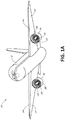
- Aircraft 10 may have a fuselage 12 and a pair of wings 14 extending laterally from the fuselage 12.
- a nacelle 16 is coupled to an underside of each wing 14.
- each nacelle 16 is coupled to a wing 14 by a pylon, or any other suitable structure capable of coupling a load to a wing 14.
- Each nacelle 16 may house an aircraft engine 15, for example, a high bypass ratio engine, which receives air through a fan 20 disposed near an inlet 19 of the nacelle 16, combusts the received air with fuel within a combustion chamber, and provides an exhaust jet through a rear-facing nozzle to propel the aircraft 10 in a forward direction. Additionally, high bypass ratio engines also receive a substantial amount of air through the inlet 19 of the nacelle 16 that is passed over or bypasses the engine 15 to provide additional thrust. The bypass air is combined with the exhaust jet and improves fuel efficiency and engine noise.
- the nacelle 16 can include a variable area fan nozzle cowling configured to vary an outlet area through which the bypass air can pass through.
- a high bypass ratio engine may be associated with a large diameter fan 20
- such engines can require a larger nacelle that must be disposed near the underside 17 of the wing 14 in order to provide for necessary clearance between the nacelle and a landing surface such as a runway.
- each nacelle 16 during flight, air flows through the inlet 19 of each nacelle 16 as well as over the outer surfaces of each nacelle 16.
- the outer surfaces of the nacelle 16 may be formed by various cowlings that are joined together to form the nacelle.
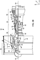
- Gas turbine engine 100 may be an example of engine 15 in FIG. 1A .
- “aft” refers to the direction associated with a tail (e.g., the back end) of an aircraft, or generally, to the direction of exhaust of gas turbine engine 100.
- “forward” refers to the direction associated with a nose (e.g., the front end) of the aircraft, or generally, to the direction of flight or motion.
- An A-R-C axis has been included to illustrate the axial (A), radial (R) and circumferential (C) directions.
- axial axis A spans parallel to axis of rotation 120.
- radially inward refers to the negative R direction towards axis of rotation 120
- radially outward refers to the R direction away from axis of rotation 120.
- Gas turbine engine 100 may comprise a two-spool turbofan that generally incorporates a fan section 122 (example of fan 20 in FIG. 1A ), a compressor section 124, a combustor section 126, and a turbine section 128. Gas turbine engine 100 may also comprise, for example, an augmenter section, and/or any other suitable system, section, or feature.
- fan section 122 may drive air along a bypass flow-path B
- compressor section 124 may further drive air along a core flow-path C for compression and communication into combustor section 126, before expansion through turbine section 128.
- FIG. 1 provides a general understanding of the sections in a gas turbine engine, and is not intended to limit the disclosure.
- an intermediate spool includes an intermediate pressure compressor ("IPC") between a low pressure compressor (“LPC”) and a high pressure compressor (“HPC”), and an intermediate pressure turbine (“IPT”) between the high pressure turbine (“HPT”) and the low pressure turbine (“LPT”).
- IPC intermediate pressure compressor
- HPC low pressure compressor
- HPC high pressure compressor
- IPT intermediate pressure turbine
- gas turbine engine 100 may comprise a low speed spool 130 and a high speed spool 132 mounted for rotation about an axis of rotation 120 relative to an engine static structure 136 via one or more bearing systems 138 (shown as, for example, bearing system 138-1 and bearing system 138-2 in FIG. 1 ). It should be understood that various bearing systems 138 at various locations may alternatively or additionally be provided, including, for example, bearing system 138, bearing system 138-1, and/or bearing system 138-2.
- low speed spool 130 may comprise an inner shaft 140 that interconnects a fan 142, a low pressure (or a first) compressor section 144, and a low pressure (or a second) turbine section 146.
- Inner shaft 140 may be connected to fan 142 through a geared architecture 148 that can drive fan 142 at a lower speed than low speed spool 130.
- Geared architecture 148 may comprise a gear assembly 160 enclosed within a gear housing 162.
- Gear assembly 160 may couple inner shaft 140 to a rotating fan structure.
- High speed spool 132 may comprise an outer shaft 150 that interconnects a high pressure compressor (“HPC") 152 (e.g., a second compressor section) and high pressure (or a first) turbine section 154.
- HPC high pressure compressor
- a combustor 156 may be located between HPC 152 and high pressure turbine 154.
- a mid-turbine frame 157 of engine static structure 136 may be located generally between high pressure turbine 154 and low pressure turbine 146.
- Mid-turbine frame 157 may support one or more bearing systems 138 in turbine section 128.
- Inner shaft 140 and outer shaft 150 may be concentric and may rotate via bearing systems 138 about axis of rotation 120.
- a "high pressure" compressor and/or turbine may experience a higher pressure than a corresponding "low pressure” compressor and/or turbine.
- the air along core airflow C may be compressed by low pressure compressor 144 and HPC 152, mixed and burned with fuel in combustor 156, and expanded over high pressure turbine 154 and low pressure turbine 146.
- Mid-turbine frame 157 may comprise airfoils 159 located in core airflow path C.
- Low pressure turbine 146 and high pressure turbine 154 may rotationally drive low speed spool 130 and high speed spool 132, respectively, in reaction to the expansion exhaust gases.
- gas turbine engine 100 may comprise a high-bypass ratio geared aircraft engine.
- the bypass ratio of gas turbine engine 100 may also be greater than ten (10:1).
- Geared architecture 148 may be an epicyclic gear train, such as a star gear system (sun gear in meshing engagement with a plurality of star gears supported by a carrier and in meshing engagement with a ring gear) or other gear system.
- Geared architecture 148 may have a gear reduction ratio of greater than about 2.3 and low pressure turbine 146 may have a pressure ratio that is greater than about five (5).
- the diameter of fan 142 may be significantly larger than that of the low pressure compressor section 144, and the low pressure turbine 146 may have a pressure ratio that is greater than about five (5:1).
- the pressure ratio of low pressure turbine 146 is measured prior to inlet of low pressure turbine 146 as related to the pressure at the outlet of low pressure turbine 146. It should be understood, however, that the above parameters are exemplary of various embodiments of a suitable geared architecture engine and that the present disclosure contemplates other turbine engines including direct drive turbofans.
- next generation turbofan engines are designed for higher efficiency and use higher pressure ratios and higher temperatures in high pressure compressor 152 than are conventionally experienced. These higher operating temperatures and pressure ratios create operating environments that cause thermal loads that are higher than the thermal loads conventionally experienced, which may shorten the operational life of current components.
- a nacelle 250 may encircle a gas turbine engine 200 (an example of engine 15 and 100 in FIGS 1A and 1B , respectively) comprising a fan 215, a high pressure compressor section 262, a low pressure compressor section 264, a combustor section 260, a high pressure turbine section 268, and/or a low pressure turbine section 270.
- gas turbine engine 200 an example of engine 15 and 100 in FIGS 1A and 1B , respectively
- nacelle 250 may comprise an inlet 201 defined by an inlet cowling 202 and an outlet 203 defined by a boat tail cowling 230.
- inlet cowling 202 may comprise an inlet cowling external surface 204, defining the outermost circumferential surface of inlet cowling 202, and an inlet cowling aft edge 210, which is the aft-most edge of inlet cowling 202.
- inlet cowling external surface 204 may comprise one or multiple parts. In various embodiments in which inlet cowling external surface 204 comprises multiple parts, at least one of which may be movable to allow access to components inside nacelle 250.
- Inlet cowling aft edge 210 may comprise an aft edge length 214, which is a length extending in a direction radially from axis of rotation 120.
- Inlet cowling aft edge 210 may comprise an outer point 205, which is the radially outermost point of inlet cowling aft edge 210.
- outer point 205 may be at the same point as an inlet cowling maximum point 207, which is the most radially outward point on inlet cowling external surface 204, depicted by length 252.
- inlet cowling aft edge 210 may be disposed aft of fan 215, and/or radially outward of low pressure compressor section 262, high pressure compressor section 264, and/or combustor section 266.
- boat tail cowling 230 may comprise a boat tail cowling external surface 232, defining the radially outermost circumferential surface of boat tail cowling 230, and a boat tail cowling forward edge 224, which is the forward-most edge of boat tail cowling 230.
- boat tail cowling 230 may be coupled and/or disposed adjacent to a thrust reverser 242.
- boat tail cowling 230 may be configured to translate in an aft direction, and in response, thrust reverser 242 may be exposed to create reverse thrust in order to slow or stop an aircraft.
- thrust reverser 242 may translate with boat tail cowling 230, or remain stationary.
- boat tail cowling 230 may be configured to remain stationary (i.e., not configured to translate in an aft direction).
- thrust reverser 242 may be disposed radially inward of boat tail cowling external surface 232 and/or boat tail cowling 230.
- boat tail cowling forward edge 224 may be coupled to and/or disposed adjacent to inlet cowling aft edge 210.
- Boat tail cowling forward edge 224 may comprise an outer point 227, which is the radially outermost point of boat tail cowling forward edge 224.
- a forward edge length 226 of boat tail cowling forward edge 224 which is a length extending in a direction radially from axis of rotation 120, may be shorter than aft edge length 214.
- a step 212 is formed between outer point 205 of inlet cowling aft edge 210 and outer point 227 of boat tail cowling forward edge 224, step 212 being the portion of inlet cowling aft edge 210 that extends above (i.e., more radially outward) than boat tail cowling forward edge 224.
- outer point 205 of inlet cowling aft edge 210 is more radially outward than outer point 227 of boat tail cowling 230 relative to axis of rotation 120.
- step 212 may be disposed aft of inlet cowling maximum point 207 and/or forward of thrust reverser 242, at least in response to boat tail cowling 230 being disposed in an exposed configuration (i.e., boat tail cowling having translated in an aft direction to expose thrust reverser 242, or exposing thrust reverser 242 another way in embodiments in which boat tail cowling 230 is stationary).
- nacelle 250 may further comprise a transition fairing 220 coupled to boat tail cowling 230 radially outward of boat tail cowling 230.
- Transition fairing 220 may comprise an inner surface 219, a forward surface 221, and a fairing ramp surface 222.
- Inner surface 219 may be coupled and/or disposed adjacent to boat tail cowling external surface 232
- forward surface 221 may be coupled and/or disposed adjacent to inlet cowling aft edge 210.
- Transition fairing 220 may be disposed adjacent to at least a portion of step 212, wherein fairing ramp surface 222 may provide a transition surface between inlet cowling aft edge 210 and boat tail cowling external surface 232.
- forward surface 221 of transition fairing 220 may not span the same distance as step 212, i.e., forward surface 221 may not extend radially outward as far as outer point 205. In various embodiments, transition fairing 220 may be disposed radially outward of thrust reverser 242.
- transition fairing 220 may be fixedly coupled to, and/or integral with, boat tail cowling 230.
- "Integral” in this context may mean no splits in material between boat tail cowling 230 and transition fairing 220, or that boat tail cowling 230 and transition fairing 220 are part of a monolithic whole.
- a transition angle 353 formed between fairing ramp surface 222, 322 and a reference line 315 parallel to axis of rotation 120 may be between 10 and 20 degrees, 12 and 17 degrees, 11 and 15 degrees, 15 and 19 degrees, or any other suitable angle.
- step 212 and transition fairing 220 allows for various benefits.
- the smaller circumference (or cross section) of boat tail cowling 230 and transition fairing 220 compared to that of inlet cowling 202 decreases the surface area of boat tail cowling external surface 232, and therefore, of nacelle 250 as a whole. Therefore, with less surface area of the external surface of nacelle 250, there is less surface area friction and drag caused by the airflow contacting the outer surfaces of nacelle 250 than if there were a flush surface between an inlet cowling and a boat tail cowling. Additionally, the smaller circumference of boat tail cowling 230 and transition fairing 220 than inlet cowling 202 decreases the amount of material in nacelle 250, decreasing the weight of nacelle 250.
- Both these aspects of the present disclosure may improve efficiency of engine 200 in moving the aircraft in flight, thus, improving fuel efficiency.
- the diameter of engine 200 and/or fan 215 may be increased (allowing more bypass air through engine 200 to increase thrust and fuel efficiency) without a need to increase the height of the aircraft or length of landing gear to allow for clearance between nacelle 250 and a landing surface, as well as between nacelle 250 and the aircraft wing.
- fan 215 and/or engine 200 may increase in size (e.g., diameter), and nacelle 250 may be coupled on a wing of an aircraft closer to the wing because of the extra clearance provided by boat tail cowling 230, step 212, and transition fairing 220.
- step 212 allows the shock wave 212A formed by passing airflow to be positioned at step 212. This allows laminar flow along inlet cowling 202, shock at step 212, then recovery of smoother airflow after the shock into laminar flow along boat tail cowling 230 until boat tail cowling 230 begins to taper radially inward toward the aft end.
- transition fairing 220 allows less of a shock wave 212A at step 212 to occur, because fairing ramp surface 222 provides a transition surface for airflow from outer point 205 inlet cowling aft edge 524 and boat tail cowling external surface 232.
- nacelle 350 may comprise an inlet cowling 302 having an inlet cowling maximum point 307 of inlet cowling external surface 304 that may not be at the same position as outer point 305 of step 312. Therefore, step 312 may be disposed aft of inlet cowling maximum point 307, and aft edge length 314 of inlet cowling aft edge 310, and the radial distance of step 312, may be less than the embodiment pictured in FIGS. 2A and 2B (in which outer point 205 of step 212 is at the same position as inlet cowling maximum point 207).
- step 312 may be between 1% and 10% less than step 212, between 2% and 6% less than step 212, or between 6% and 10% less than step 212.
- the surface between inlet cowling maximum point 307 and outer point 305 may be a convergent surface 308 sloping between inlet cowling maximum point 307 and outer point 305. Such embodiments may allow control of the shockwave 312A so that it is located at or near step 312.
- convergent surface 308 may be substantially flat (e.g., wherein the term "substantially” in this context only may refer to plus or minus 5 degrees), convex, or concave to affect the aerodynamics of nacelle 350.
- a convergent surface angle formed between convergent surface 308 and an axial reference line parallel to axis of rotation 120 may be 0.01 and 18 degrees, between 5 and 12 degrees, between 10 and 18 degrees, between 1 and 10 degrees, or any other suitable angle.
- forward surface 321 of transition fairing 320 may span the same radial distance as step 312. Therefore, fairing ramp surface 322 of transition fairing 320 may be flush with convergent surface 380 of inlet cowling 302.
- Fairing ramp surface 322 may have a different transition angle 353 than the convergent surface angle of convergent surface 308, or transition angle 353 and the convergent surface angle of convergent surface 308 may be the same.
- forward surface 321 of transition fairing 320 may not span the same distance as step 312, i.e., forward surface 321 may not extend radially outward as far as outer point 305.
- nacelle 450 may comprise inlet cowling 402, having an inlet cowling external surface 404 and inlet cowling aft edge 410.
- inlet cowling aft edge 410 may be angled forward or aft relative to a perpendicular position to axis of rotation 120. Therefore, step 412 between inlet cowling maximum point 407 (which may also be outer point 405 of inlet cowling aft edge 410) may be angled along at least a portion of inlet cowling aft edge 410 and/or aft edge length 414.
- a portion of step 412 may be angled, while a thrust reverser portion 411 may not be angled (i.e., substantially perpendicular to axis of rotation 120 (plus or minus 5 degrees)).
- boat tail cowling forward edge 424 may be complementarily angled at least partially along forward edge length 426 to the angle of inlet cowling aft edge 410 such that boat tail cowling forward edge 424 remains adjacent to inlet cowling aft edge 410 when boat tail cowling 430 is in its forward-most configuration (i.e., boat tail cowling 430 has not translated aft to expose thrust reverser 242 in embodiments in which boat tail cowling 430 is configured to translate).
- the angle 416 formed between step 412 and an axial reference line 121 parallel to axis of rotation 120 may be between 45 and 90 degrees, 60 and 80 degrees, 75 and 90 degrees, 50 and 65 degrees, or any other suitable angle.
- step 412 may cause similar aerodynamic benefits as discussed in relation to FIGS. 3A and 3B and convergent surface 308.
- forward surface 421 of transition fairing 420 may be complementarily angled at least partially along step 412 such that forward surface 421 remains adjacent to inlet cowling aft edge 410 when boat tail cowling 430 is in its forward-most configuration (i.e., boat tail cowling 430 has not translated aft to expose thrust reverser 242). Therefore, fairing ramp surface 422 may provide a transition surface between boat tail cowling external surface 432 and step 412.
- forward surface 421 may span a portion or the entire length of step 412.
- nacelle 550 may comprise an inlet cowling 502 comprising a thrust reverser housing 509, in which thrust reverser 542 may be disposed in response to boat tail cowling 530 being in a forward-most configuration 541 (as shown in FIG. 5A ).
- boat tail cowling external surface 532 of boat tail cowling 530 may create step 512 by having a radial flange 513 protruding radially outward from a boat tail cowling forward portion 535, wherein radial flange 513 comprises boat tail cowling forward edge 524.
- a flange outer point 536 of radial flange 513 may be more radially outward from axis of rotation 120 than a laminar portion distance 526 of boat tail cowling 530 such that step 512 is formed.
- Step 512 may be the portion of radial flange 513 more radially outward than laminar portion distance 526.
- flange outer point 536 may be the same distance radially outward of axis of rotation 120 as outer point 505 of inlet cowling aft edge 510 (the most radially outward point of inlet cowling aft edge 510) such that inlet cowling external surface 504 is flush with flange outer point 536 (i.e., flange outer point 536 is the same distance radially outward from axis of rotation 120 as outer point 505 of inlet cowling aft edge 510 and/or inlet cowling maximum point 507).
- outer point 505 and inlet cowling maximum point 507 are not at the same position on inlet cowling external surface 504, there may be a convergent surface (similar to convergent surface 308 in FIGS. 3A and 3B ) between inlet cowling maximum point 507 and outer point 505 and/or flange outer point 536.
- flange outer point 536 may not be at the same height (where height refers to a radially outward distance from axis of rotation 120) as outer point 505 of inlet cowling aft edge 510, such that there is a step between flange outer point 536 and outer point 505 of inlet cowling aft edge 510.
- flange outer point 536 may be angled, concave, or convex in any suitable manner to affect the aerodynamics of nacelle 550 in flight.
- transition fairing 520 may be coupled to boat tail cowling 530, wherein inner surface 519 is coupled and/or disposed adjacent to boat tail cowling external surface 532, and forward surface 521 is coupled and/or disposed adjacent to radial flange 513.
- Fairing ramp surface 522 may provide a transition surface between radial flange 513 and boat tail cowling external surface 532.
- forward surface 521 may span radially outward the same distance as flange outer point 536, or may span less radially outward than flange outer point 536.
- boat tail cowling 530 may be configured to translate aft to an exposed configuration 543 to expose thrust reverser 542 to create reverse thrust to slow or stop an aircraft.
- Exposed configuration 543 may be any translation of boat tail cowling 530 in an aft direction such that any portion of thrust reverser 542 is exposed.
- thrust reverser 542 may be coupled to boat tail cowling forward edge 524 such that in response to boat tail cowling 530 translating in an aft direction, thrust reverser 542 likewise translates aft, out thrust reverser housing 509 to become exposed and utilized.
- the thrust reverser may be disposed radially inward of boat tail cowling 530 when boat tail cowling 530 is in forward-most configuration 541, similar to the disposition of thrust reverser 242 in FIGS. 2A-4 .
- references to "one embodiment”, “an embodiment”, “various embodiments”, etc. indicate that the embodiment described may include a particular feature, structure, or characteristic, but every embodiment may not necessarily include the particular feature, structure, or characteristic. Moreover, such phrases are not necessarily referring to the same embodiment. Further, when a particular feature, structure, or characteristic is described in connection with an embodiment, it is submitted that it is within the knowledge of one skilled in the art to affect such feature, structure, or characteristic in connection with other embodiments whether or not explicitly described. After reading the description, it will be apparent to one skilled in the relevant art(s) how to implement the disclosure in alternative embodiments.
Landscapes
- Engineering & Computer Science (AREA)
- Aviation & Aerospace Engineering (AREA)
- Chemical & Material Sciences (AREA)
- Combustion & Propulsion (AREA)
- Mechanical Engineering (AREA)
- General Engineering & Computer Science (AREA)
- Structures Of Non-Positive Displacement Pumps (AREA)
Abstract
Description
- This disclosure generally relates to nacelles on aircraft.
- A nacelle is a casing or housing that holds an engine and/or other equipment on an aircraft. Nacelles are often coupled to an underside of an aircraft wing, for example, by a pylon. Nacelles are typically designed to enhance aerodynamic efficiency, and to fit under the aircraft wing without hanging too close to, or contacting, the ground.
- In various embodiments, a nacelle encircling an engine about an axis of rotation may comprise an inlet cowling defining an inlet of the nacelle, wherein the inlet cowling comprises an inlet cowling maximum point and an inlet cowling aft edge, wherein the inlet cowling aft edge comprises an aft edge length; and a boat tail cowling disposed aft of the inlet cowling, wherein the boat tail cowling comprises a boat tail cowling forward edge having a forward edge length, and wherein the boat tail cowling forward edge is disposed adjacent to the inlet cowling aft edge. In various embodiments, the forward edge length may be shorter than the aft edge length, forming a step, the step being defined by a portion of the inlet cowling aft edge that is radially outward of the boat tail cowling forward edge. The nacelle may further comprise a transition fairing coupled to a boat tail cowling external surface of the boat tail cowling, wherein the transition fairing may comprise a fairing forward edge disposed adjacent to the inlet cowling aft edge and a fairing ramp surface providing a transition surface between the inlet cowling aft edge and the boat tail cowling external surface. In various embodiments, the transition fairing may be integral with the boat tail cowling.
- In various embodiments, the nacelle may further comprise a thrust reverser coupled to the inlet cowling and the boat tail cowling, wherein the boat tail cowling may be configured to translate in an aft direction, wherein the boat tail cowling forward edge is disposed adjacent to the inlet cowling aft edge when the boat tail cowling is in a forward-most configuration, and wherein the thrust reverser is configured to be in an exposed configuration in response to the boat tail cowling translating in the aft direction. In various embodiments, the step may be disposed forward of the thrust reverser, and the transition fairing may be disposed radially outward of the thrust reverser. In various embodiments, the inlet cowling may comprise a convergent surface between the inlet cowling maximum point and an outer point of the inlet cowling aft edge. In various embodiments, the fairing ramp surface may span between the boat tail cowling external surface and the outer point. In various embodiments, the convergent surface and the fairing ramp surface may be flush. In various embodiments, the fairing ramp surface may span between the boat tail cowling external surface and a point along inlet cowling aft edge that is radially inward of the outer point. In various embodiments, a transition angle formed between the fairing ramp surface and a reference line parallel to the axis of rotation may be between 10 and 20 degrees. In various embodiments, at least a portion of the inlet cowling aft edge comprises an angled portion. In various embodiments, an angle formed between the angled portion and a reference line parallel to the axis of rotation may be between 45 and 90 degrees.
- In various embodiments, an aircraft may comprise a gas turbine engine; and a nacelle encircling the gas turbine engine. The nacelle may comprise an inlet cowling defining an inlet of the nacelle, wherein the inlet cowling comprises an inlet cowling maximum point and an inlet cowling aft edge, wherein the inlet cowling aft edge comprises an aft edge length; and a boat tail cowling disposed aft of the inlet cowling, wherein the boat tail cowling comprises a boat tail cowling forward edge having a forward edge length, and wherein the boat tail cowling forward edge is disposed adjacent to the inlet cowling aft edge. The forward edge length may be shorter than the aft edge length, forming a step, the step being defined by a portion of the inlet cowling aft edge that is radially outward of the boat tail cowling forward edge. The nacelle may further comprise a transition fairing coupled to a boat tail cowling external surface of the boat tail cowling, wherein the transition fairing comprises a fairing forward edge disposed adjacent to the inlet cowling aft edge and a fairing ramp surface providing a transition surface between the inlet cowling aft edge and the boat tail cowling external surface. In various embodiments, the transition fairing may be integral with the boat tail cowling.
- In various embodiments, the nacelle of the aircraft may further comprise a thrust reverser coupled to the inlet cowling and the boat tail cowling, wherein the boat tail cowling may be configured to translate in an aft direction, wherein the boat tail cowling forward edge is disposed adjacent to the inlet cowling aft edge when the boat tail cowling is in a forward-most configuration, and wherein the thrust reverser is configured to be in an exposed configuration in response to the boat tail cowling translating in the aft direction. In various embodiments, the step may be disposed forward of the thrust reverser and the transition fairing may be disposed radially outward of the thrust reverser. In various embodiments, the inlet cowling may comprise a convergent surface between the inlet cowling maximum point and an outer point of the inlet cowling aft edge. In various embodiments, the fairing ramp surface may span between the boat tail cowling external surface and the outer point. In various embodiments, the fairing ramp surface may span between the boat tail cowling external surface and a point along inlet cowling aft edge that is radially inward of the outer point. In various embodiments, a transition angle formed between the fairing ramp surface and a reference line parallel to the axis of rotation may be between 10 and 20 degrees.
- In various embodiments, a nacelle configured to encircle an engine disposed about an axis of rotation may comprise an inlet cowling defining an inlet, wherein the inlet cowling comprises an inlet cowling aft edge; and a boat tail cowling comprising a radial flange protruding radially outward from a boat tail cowling forward portion, wherein the radial flange comprises a boat tail forward edge disposed adjacent to the inlet cowling aft edge. In various embodiments, the boat tail cowling may comprise a step formed by a flange outer point of the radial flange being more radially outward from the axis of rotation than a laminar portion distance of the boat tail cowling, the step being defined by a portion of the radial flange that is radially outward of the laminar portion distance. In various embodiments, the nacelle may further comprise a transition fairing coupled to a boat tail cowling external surface of the boat tail cowling, wherein the transition fairing comprises a fairing forward edge disposed adjacent to the radial flange and a fairing ramp surface providing a transition surface between the radial flange and the boat tail cowling external surface.
- The subject matter of the present disclosure is particularly pointed out and distinctly claimed in the concluding portion of the specification. A more complete understanding of the present disclosure, however, may best be obtained by referring to the detailed description and claims when considered in connection with the drawing figures. Elements with the like element numbering throughout the figures are intended to be the same.
-
FIG. 1A illustrates a perspective view of an aircraft incorporating a nacelle, in accordance with various embodiments; -
FIG. 1B illustrates a gas turbine engine, in accordance with various embodiments; -
FIGS. 2A and 2B illustrate a nacelle comprising a transition fairing between cowlings, in accordance with various embodiments; -
FIGS. 3A and 3B illustrate a nacelle comprising a transition fairing between cowlings with a convergent surface, in accordance with various embodiments; -
FIG. 4 illustrates a nacelle comprising an angled step and a transition fairing between cowlings, in accordance with various embodiments; -
FIG. 5A illustrates a nacelle comprising an additional example of a transition fairing between cowlings, in accordance with various embodiments; and -
FIG. 5B illustrates a nacelle comprising the additional example of a transition fairing between cowlings exposing a thrust reverser, in accordance with various embodiments. - All ranges may include the upper and lower values, and all ranges and ratio limits disclosed herein may be combined. It is to be understood that unless specifically stated otherwise, references to "a," "an," and/or "the" may include one or more than one and that reference to an item in the singular may also include the item in the plural.
- The detailed description of various embodiments herein makes reference to the accompanying drawings, which show various embodiments by way of illustration. While these various embodiments are described in sufficient detail to enable those skilled in the art to practice the disclosure, it should be understood that other embodiments may be realized and that logical, chemical, and mechanical changes may be made without departing from the scope of the disclosure. Thus, the detailed description herein is presented for purposes of illustration only and not of limitation. Furthermore, any reference to singular includes plural embodiments, and any reference to more than one component or step may include a singular embodiment or step. Also, any reference to attached, fixed, connected, or the like may include permanent, removable, temporary, partial, full, and/or any other possible attachment option. Additionally, any reference to without contact (or similar phrases) may also include reduced contact or minimal contact.
- In various embodiments, and with reference to
FIG. 1A anaircraft 10 is depicted.Aircraft 10 may have afuselage 12 and a pair ofwings 14 extending laterally from thefuselage 12. Anacelle 16 is coupled to an underside of eachwing 14. Although not illustrated inFIG. 1A , in various embodiments, eachnacelle 16 is coupled to awing 14 by a pylon, or any other suitable structure capable of coupling a load to awing 14. - Each
nacelle 16 may house anaircraft engine 15, for example, a high bypass ratio engine, which receives air through afan 20 disposed near aninlet 19 of thenacelle 16, combusts the received air with fuel within a combustion chamber, and provides an exhaust jet through a rear-facing nozzle to propel theaircraft 10 in a forward direction. Additionally, high bypass ratio engines also receive a substantial amount of air through theinlet 19 of thenacelle 16 that is passed over or bypasses theengine 15 to provide additional thrust. The bypass air is combined with the exhaust jet and improves fuel efficiency and engine noise. In various embodiments, thenacelle 16 can include a variable area fan nozzle cowling configured to vary an outlet area through which the bypass air can pass through. Because a high bypass ratio engine may be associated with alarge diameter fan 20, such engines can require a larger nacelle that must be disposed near theunderside 17 of thewing 14 in order to provide for necessary clearance between the nacelle and a landing surface such as a runway. - With further reference to
FIG. 1A , during flight, air flows through theinlet 19 of eachnacelle 16 as well as over the outer surfaces of eachnacelle 16. The outer surfaces of thenacelle 16 may be formed by various cowlings that are joined together to form the nacelle. The greater the surface area of nacelle 16 (i.e., the area in contact with external airflow during flight) formed by the various cowlings, the greater the external drag on thenacelle 16 andaircraft 10 as a whole. - In various embodiments, and with reference to
FIG. 1B , agas turbine engine 100 is disclosed.Gas turbine engine 100 may be an example ofengine 15 inFIG. 1A . As used herein, "aft" refers to the direction associated with a tail (e.g., the back end) of an aircraft, or generally, to the direction of exhaust ofgas turbine engine 100. As used herein, "forward" refers to the direction associated with a nose (e.g., the front end) of the aircraft, or generally, to the direction of flight or motion. An A-R-C axis has been included to illustrate the axial (A), radial (R) and circumferential (C) directions. For clarity, axial axis A spans parallel to axis ofrotation 120. As utilized herein, radially inward refers to the negative R direction towards axis ofrotation 120, and radially outward refers to the R direction away from axis ofrotation 120. -
Gas turbine engine 100 may comprise a two-spool turbofan that generally incorporates a fan section 122 (example offan 20 inFIG. 1A ), acompressor section 124, acombustor section 126, and aturbine section 128.Gas turbine engine 100 may also comprise, for example, an augmenter section, and/or any other suitable system, section, or feature. In operation,fan section 122 may drive air along a bypass flow-path B, whilecompressor section 124 may further drive air along a core flow-path C for compression and communication intocombustor section 126, before expansion throughturbine section 128.FIG. 1 provides a general understanding of the sections in a gas turbine engine, and is not intended to limit the disclosure. The present disclosure may extend to all types of applications and to all types of turbine engines, including, for example, turbojets, turboshafts, and three spool (plus fan) turbofans wherein an intermediate spool includes an intermediate pressure compressor ("IPC") between a low pressure compressor ("LPC") and a high pressure compressor ("HPC"), and an intermediate pressure turbine ("IPT") between the high pressure turbine ("HPT") and the low pressure turbine ("LPT"). - In various embodiments,
gas turbine engine 100 may comprise alow speed spool 130 and ahigh speed spool 132 mounted for rotation about an axis ofrotation 120 relative to an enginestatic structure 136 via one or more bearing systems 138 (shown as, for example, bearing system 138-1 and bearing system 138-2 inFIG. 1 ). It should be understood that various bearingsystems 138 at various locations may alternatively or additionally be provided, including, for example,bearing system 138, bearing system 138-1, and/or bearing system 138-2. - In various embodiments,
low speed spool 130 may comprise aninner shaft 140 that interconnects afan 142, a low pressure (or a first)compressor section 144, and a low pressure (or a second)turbine section 146.Inner shaft 140 may be connected to fan 142 through a gearedarchitecture 148 that can drivefan 142 at a lower speed thanlow speed spool 130.Geared architecture 148 may comprise agear assembly 160 enclosed within agear housing 162.Gear assembly 160 may coupleinner shaft 140 to a rotating fan structure.High speed spool 132 may comprise anouter shaft 150 that interconnects a high pressure compressor ("HPC") 152 (e.g., a second compressor section) and high pressure (or a first)turbine section 154. Acombustor 156 may be located betweenHPC 152 andhigh pressure turbine 154. Amid-turbine frame 157 of enginestatic structure 136 may be located generally betweenhigh pressure turbine 154 andlow pressure turbine 146.Mid-turbine frame 157 may support one ormore bearing systems 138 inturbine section 128.Inner shaft 140 andouter shaft 150 may be concentric and may rotate via bearingsystems 138 about axis ofrotation 120. As used herein, a "high pressure" compressor and/or turbine may experience a higher pressure than a corresponding "low pressure" compressor and/or turbine. - In various embodiments, the air along core airflow C may be compressed by
low pressure compressor 144 andHPC 152, mixed and burned with fuel incombustor 156, and expanded overhigh pressure turbine 154 andlow pressure turbine 146.Mid-turbine frame 157 may compriseairfoils 159 located in core airflow path C.Low pressure turbine 146 andhigh pressure turbine 154 may rotationally drivelow speed spool 130 andhigh speed spool 132, respectively, in reaction to the expansion exhaust gases. - In various embodiments,
gas turbine engine 100 may comprise a high-bypass ratio geared aircraft engine. The bypass ratio ofgas turbine engine 100 may also be greater than ten (10:1).Geared architecture 148 may be an epicyclic gear train, such as a star gear system (sun gear in meshing engagement with a plurality of star gears supported by a carrier and in meshing engagement with a ring gear) or other gear system.Geared architecture 148 may have a gear reduction ratio of greater than about 2.3 andlow pressure turbine 146 may have a pressure ratio that is greater than about five (5). The diameter offan 142 may be significantly larger than that of the lowpressure compressor section 144, and thelow pressure turbine 146 may have a pressure ratio that is greater than about five (5:1). The pressure ratio oflow pressure turbine 146 is measured prior to inlet oflow pressure turbine 146 as related to the pressure at the outlet oflow pressure turbine 146. It should be understood, however, that the above parameters are exemplary of various embodiments of a suitable geared architecture engine and that the present disclosure contemplates other turbine engines including direct drive turbofans. - The next generation turbofan engines are designed for higher efficiency and use higher pressure ratios and higher temperatures in
high pressure compressor 152 than are conventionally experienced. These higher operating temperatures and pressure ratios create operating environments that cause thermal loads that are higher than the thermal loads conventionally experienced, which may shorten the operational life of current components. - With reference to
FIGS. 2A and 2B (FIG. 2B depicting an enlarged view ofarea 255 fromFIG. 2A ), anacelle 250 may encircle a gas turbine engine 200 (an example ofengine FIGS 1A and1B , respectively) comprising afan 215, a highpressure compressor section 262, a lowpressure compressor section 264, a combustor section 260, a highpressure turbine section 268, and/or a lowpressure turbine section 270. In various embodiments,nacelle 250 may comprise an inlet 201 defined by aninlet cowling 202 and anoutlet 203 defined by aboat tail cowling 230. In various embodiments,inlet cowling 202 may comprise an inlet cowlingexternal surface 204, defining the outermost circumferential surface ofinlet cowling 202, and an inlet cowling aftedge 210, which is the aft-most edge ofinlet cowling 202. In various embodiments, inlet cowlingexternal surface 204 may comprise one or multiple parts. In various embodiments in which inlet cowlingexternal surface 204 comprises multiple parts, at least one of which may be movable to allow access to components insidenacelle 250. Inlet cowling aftedge 210 may comprise anaft edge length 214, which is a length extending in a direction radially from axis ofrotation 120. Inlet cowling aftedge 210 may comprise anouter point 205, which is the radially outermost point of inlet cowling aftedge 210. In various embodiments,outer point 205 may be at the same point as an inlet cowlingmaximum point 207, which is the most radially outward point on inlet cowlingexternal surface 204, depicted bylength 252. - In various embodiments, inlet cowling aft
edge 210 may be disposed aft offan 215, and/or radially outward of lowpressure compressor section 262, highpressure compressor section 264, and/orcombustor section 266. - In various embodiments,
boat tail cowling 230 may comprise a boat tail cowlingexternal surface 232, defining the radially outermost circumferential surface ofboat tail cowling 230, and a boat tail cowling forwardedge 224, which is the forward-most edge ofboat tail cowling 230. In various embodiments,boat tail cowling 230 may be coupled and/or disposed adjacent to athrust reverser 242. In various embodiments,boat tail cowling 230 may be configured to translate in an aft direction, and in response, thrustreverser 242 may be exposed to create reverse thrust in order to slow or stop an aircraft. In various embodiments, thrustreverser 242 may translate withboat tail cowling 230, or remain stationary. In various embodiments,boat tail cowling 230 may be configured to remain stationary (i.e., not configured to translate in an aft direction). In various embodiments, thrustreverser 242 may be disposed radially inward of boat tail cowlingexternal surface 232 and/orboat tail cowling 230. - In various embodiments, boat tail cowling forward edge 224 may be coupled to and/or disposed adjacent to inlet cowling aft
edge 210. Boat tail cowling forward edge 224 may comprise anouter point 227, which is the radially outermost point of boat tail cowling forwardedge 224. In various embodiments, aforward edge length 226 of boat tail cowling forwardedge 224, which is a length extending in a direction radially from axis ofrotation 120, may be shorter thanaft edge length 214. Therefore, astep 212 is formed betweenouter point 205 of inlet cowling aftedge 210 andouter point 227 of boat tail cowling forwardedge 224, step 212 being the portion of inlet cowling aftedge 210 that extends above (i.e., more radially outward) than boat tail cowling forwardedge 224. Stated another way,outer point 205 of inlet cowling aftedge 210 is more radially outward thanouter point 227 ofboat tail cowling 230 relative to axis ofrotation 120. In various embodiments,step 212 may be disposed aft of inlet cowlingmaximum point 207 and/or forward ofthrust reverser 242, at least in response toboat tail cowling 230 being disposed in an exposed configuration (i.e., boat tail cowling having translated in an aft direction to expose thrustreverser 242, or exposingthrust reverser 242 another way in embodiments in whichboat tail cowling 230 is stationary). - In various embodiments,
nacelle 250 may further comprise a transition fairing 220 coupled toboat tail cowling 230 radially outward ofboat tail cowling 230. Transition fairing 220 may comprise aninner surface 219, aforward surface 221, and afairing ramp surface 222.Inner surface 219 may be coupled and/or disposed adjacent to boat tail cowlingexternal surface 232, andforward surface 221 may be coupled and/or disposed adjacent to inlet cowling aftedge 210. Transition fairing 220 may be disposed adjacent to at least a portion ofstep 212, wherein fairingramp surface 222 may provide a transition surface between inlet cowling aftedge 210 and boat tail cowlingexternal surface 232. In various embodiments,forward surface 221 of transition fairing 220 may not span the same distance asstep 212, i.e.,forward surface 221 may not extend radially outward as far asouter point 205. In various embodiments, transition fairing 220 may be disposed radially outward ofthrust reverser 242. - In various embodiments, transition fairing 220 may be fixedly coupled to, and/or integral with,
boat tail cowling 230. "Integral" in this context may mean no splits in material betweenboat tail cowling 230 and transition fairing 220, or thatboat tail cowling 230 and transition fairing 220 are part of a monolithic whole. In various embodiments, with momentary reference toFIGS. 2A, 2B ,3A, and 3B , atransition angle 353 formed betweenfairing ramp surface reference line 315 parallel to axis ofrotation 120 may be between 10 and 20 degrees, 12 and 17 degrees, 11 and 15 degrees, 15 and 19 degrees, or any other suitable angle. - The presence of
step 212 and transition fairing 220 allows for various benefits. The smaller circumference (or cross section) ofboat tail cowling 230 and transition fairing 220 compared to that ofinlet cowling 202 decreases the surface area of boat tail cowlingexternal surface 232, and therefore, ofnacelle 250 as a whole. Therefore, with less surface area of the external surface ofnacelle 250, there is less surface area friction and drag caused by the airflow contacting the outer surfaces ofnacelle 250 than if there were a flush surface between an inlet cowling and a boat tail cowling. Additionally, the smaller circumference ofboat tail cowling 230 and transition fairing 220 thaninlet cowling 202 decreases the amount of material innacelle 250, decreasing the weight ofnacelle 250. Both these aspects of the present disclosure may improve efficiency ofengine 200 in moving the aircraft in flight, thus, improving fuel efficiency. Furthermore, with a decreased circumference ofboat tail cowling 230 and transition fairing 220, the diameter ofengine 200 and/orfan 215 may be increased (allowing more bypass air throughengine 200 to increase thrust and fuel efficiency) without a need to increase the height of the aircraft or length of landing gear to allow for clearance betweennacelle 250 and a landing surface, as well as betweennacelle 250 and the aircraft wing. That is to say,fan 215 and/orengine 200 may increase in size (e.g., diameter), andnacelle 250 may be coupled on a wing of an aircraft closer to the wing because of the extra clearance provided byboat tail cowling 230,step 212, and transition fairing 220. Regarding airflow during flight,step 212 allows theshock wave 212A formed by passing airflow to be positioned atstep 212. This allows laminar flow alonginlet cowling 202, shock atstep 212, then recovery of smoother airflow after the shock into laminar flow alongboat tail cowling 230 untilboat tail cowling 230 begins to taper radially inward toward the aft end. The presence of transition fairing 220 allows less of ashock wave 212A atstep 212 to occur, because fairingramp surface 222 provides a transition surface for airflow fromouter point 205 inlet cowling aftedge 524 and boat tail cowlingexternal surface 232. - With reference to
FIGS. 3A and 3B (FIG. 3B depicting an enlarged view ofarea 355 fromFIG. 3A ), in various embodiments,nacelle 350 may comprise aninlet cowling 302 having an inlet cowlingmaximum point 307 of inlet cowlingexternal surface 304 that may not be at the same position asouter point 305 ofstep 312. Therefore, step 312 may be disposed aft of inlet cowlingmaximum point 307, andaft edge length 314 of inlet cowling aftedge 310, and the radial distance ofstep 312, may be less than the embodiment pictured inFIGS. 2A and 2B (in whichouter point 205 ofstep 212 is at the same position as inlet cowling maximum point 207). In various embodiments, with momentary combined reference toFIGS. 2A, 2B ,3A, and 3B ,step 312 may be between 1% and 10% less thanstep 212, between 2% and 6% less thanstep 212, or between 6% and 10% less thanstep 212. The surface between inlet cowlingmaximum point 307 andouter point 305 may be aconvergent surface 308 sloping between inlet cowlingmaximum point 307 andouter point 305. Such embodiments may allow control of the shockwave 312A so that it is located at ornear step 312. - In various embodiments,
convergent surface 308 may be substantially flat (e.g., wherein the term "substantially" in this context only may refer to plus or minus 5 degrees), convex, or concave to affect the aerodynamics ofnacelle 350. In various embodiments, a convergent surface angle formed betweenconvergent surface 308 and an axial reference line parallel to axis ofrotation 120 may be 0.01 and 18 degrees, between 5 and 12 degrees, between 10 and 18 degrees, between 1 and 10 degrees, or any other suitable angle. In various embodiments,forward surface 321 of transition fairing 320 may span the same radial distance asstep 312. Therefore, fairingramp surface 322 of transition fairing 320 may be flush with convergent surface 380 ofinlet cowling 302.Fairing ramp surface 322 may have adifferent transition angle 353 than the convergent surface angle ofconvergent surface 308, ortransition angle 353 and the convergent surface angle ofconvergent surface 308 may be the same. In various embodiments,forward surface 321 of transition fairing 320 may not span the same distance asstep 312, i.e.,forward surface 321 may not extend radially outward as far asouter point 305. - With reference to
FIG. 4 , in various embodiments,nacelle 450 may compriseinlet cowling 402, having an inlet cowlingexternal surface 404 and inlet cowling aftedge 410. In various embodiments, inlet cowling aftedge 410 may be angled forward or aft relative to a perpendicular position to axis ofrotation 120. Therefore, step 412 between inlet cowling maximum point 407 (which may also beouter point 405 of inlet cowling aft edge 410) may be angled along at least a portion of inlet cowling aftedge 410 and/oraft edge length 414. In various embodiments, a portion ofstep 412 may be angled, while athrust reverser portion 411 may not be angled (i.e., substantially perpendicular to axis of rotation 120 (plus or minus 5 degrees)). - In various embodiments, boat tail cowling forward edge 424 may be complementarily angled at least partially along
forward edge length 426 to the angle of inlet cowling aftedge 410 such that boat tail cowling forward edge 424 remains adjacent to inlet cowling aftedge 410 whenboat tail cowling 430 is in its forward-most configuration (i.e.,boat tail cowling 430 has not translated aft to expose thrustreverser 242 in embodiments in whichboat tail cowling 430 is configured to translate). In various embodiments, the angle 416 formed betweenstep 412 and anaxial reference line 121 parallel to axis ofrotation 120 may be between 45 and 90 degrees, 60 and 80 degrees, 75 and 90 degrees, 50 and 65 degrees, or any other suitable angle. Such angling ofstep 412 may cause similar aerodynamic benefits as discussed in relation toFIGS. 3A and 3B andconvergent surface 308. Likewise, forward surface 421 of transition fairing 420 may be complementarily angled at least partially alongstep 412 such thatforward surface 421 remains adjacent to inlet cowling aftedge 410 whenboat tail cowling 430 is in its forward-most configuration (i.e.,boat tail cowling 430 has not translated aft to expose thrust reverser 242). Therefore, fairingramp surface 422 may provide a transition surface between boat tail cowlingexternal surface 432 andstep 412. In various embodiments,forward surface 421 may span a portion or the entire length ofstep 412. - In various embodiments, with reference to
FIGS. 5A and5B ,nacelle 550 may comprise aninlet cowling 502 comprising a thrust reverserhousing 509, in whichthrust reverser 542 may be disposed in response toboat tail cowling 530 being in a forward-most configuration 541 (as shown inFIG. 5A ). In various embodiments, boat tail cowlingexternal surface 532 ofboat tail cowling 530 may createstep 512 by having aradial flange 513 protruding radially outward from a boat tail cowlingforward portion 535, whereinradial flange 513 comprises boat tail cowling forwardedge 524. That is, a flangeouter point 536 ofradial flange 513 may be more radially outward from axis ofrotation 120 than alaminar portion distance 526 ofboat tail cowling 530 such thatstep 512 is formed. Step 512 may be the portion ofradial flange 513 more radially outward thanlaminar portion distance 526. - In various embodiments, flange
outer point 536 may be the same distance radially outward of axis ofrotation 120 asouter point 505 of inlet cowling aft edge 510 (the most radially outward point of inlet cowling aft edge 510) such that inlet cowlingexternal surface 504 is flush with flange outer point 536 (i.e., flangeouter point 536 is the same distance radially outward from axis ofrotation 120 asouter point 505 of inlet cowling aftedge 510 and/or inlet cowling maximum point 507). In various embodiments in whichouter point 505 and inlet cowlingmaximum point 507 are not at the same position on inlet cowlingexternal surface 504, there may be a convergent surface (similar toconvergent surface 308 inFIGS. 3A and 3B ) between inlet cowlingmaximum point 507 andouter point 505 and/or flangeouter point 536. In various embodiments, flangeouter point 536 may not be at the same height (where height refers to a radially outward distance from axis of rotation 120) asouter point 505 of inlet cowling aftedge 510, such that there is a step between flangeouter point 536 andouter point 505 of inlet cowling aftedge 510. In various embodiments, flangeouter point 536 may be angled, concave, or convex in any suitable manner to affect the aerodynamics ofnacelle 550 in flight. - In various embodiments, transition fairing 520 may be coupled to
boat tail cowling 530, whereininner surface 519 is coupled and/or disposed adjacent to boat tail cowlingexternal surface 532, andforward surface 521 is coupled and/or disposed adjacent toradial flange 513.Fairing ramp surface 522 may provide a transition surface betweenradial flange 513 and boat tail cowlingexternal surface 532. In various embodiments,forward surface 521 may span radially outward the same distance as flangeouter point 536, or may span less radially outward than flangeouter point 536. - In various embodiments, with further reference to
FIGS. 5A and5B ,boat tail cowling 530 may be configured to translate aft to an exposedconfiguration 543 to expose thrustreverser 542 to create reverse thrust to slow or stop an aircraft.Exposed configuration 543 may be any translation ofboat tail cowling 530 in an aft direction such that any portion ofthrust reverser 542 is exposed. In such embodiments, thrustreverser 542 may be coupled to boat tail cowling forward edge 524 such that in response toboat tail cowling 530 translating in an aft direction, thrustreverser 542 likewise translates aft, out thrust reverserhousing 509 to become exposed and utilized. In various embodiments comprisingradial flange 513, the thrust reverser may be disposed radially inward ofboat tail cowling 530 whenboat tail cowling 530 is inforward-most configuration 541, similar to the disposition ofthrust reverser 242 inFIGS. 2A-4 . - Benefits, other advantages, and solutions to problems have been described herein with regard to specific embodiments. Furthermore, the connecting lines shown in the various figures contained herein are intended to represent exemplary functional relationships and/or physical couplings between the various elements. It should be noted that many alternative or additional functional relationships or physical connections may be present in a practical system. However, the benefits, advantages, solutions to problems, and any elements that may cause any benefit, advantage, or solution to occur or become more pronounced are not to be construed as critical, required, or essential features or elements of the disclosure. The scope of the disclosure is accordingly to be limited by nothing other than the appended claims, in which reference to an element in the singular is not intended to mean "one and only one" unless explicitly so stated, but rather "one or more." Moreover, where a phrase similar to "at least one of A, B, or C" is used in the claims, it is intended that the phrase be interpreted to mean that A alone may be present in an embodiment, B alone may be present in an embodiment, C alone may be present in an embodiment, or that any combination of the elements A, B and C may be present in a single embodiment; for example, A and B, A and C, B and C, or A and B and C. Different cross-hatching is used throughout the figures to denote different parts but not necessarily to denote the same or different materials.
- Systems, methods and apparatus are provided herein. In the detailed description herein, references to "one embodiment", "an embodiment", "various embodiments", etc., indicate that the embodiment described may include a particular feature, structure, or characteristic, but every embodiment may not necessarily include the particular feature, structure, or characteristic. Moreover, such phrases are not necessarily referring to the same embodiment. Further, when a particular feature, structure, or characteristic is described in connection with an embodiment, it is submitted that it is within the knowledge of one skilled in the art to affect such feature, structure, or characteristic in connection with other embodiments whether or not explicitly described. After reading the description, it will be apparent to one skilled in the relevant art(s) how to implement the disclosure in alternative embodiments.
- Furthermore, no element, component, or method step in the present disclosure is intended to be dedicated to the public regardless of whether the element, component, or method step is explicitly recited in the claims. No claim element herein is to be construed under the provisions of 35 U.S.C. 112(f) unless the element is expressly recited using the phrase "means for." As used herein, the terms "comprises", "comprising", or any other variation thereof, are intended to cover a non-exclusive inclusion, such that a process, method, article, or apparatus that comprises a list of elements does not include only those elements but may include other elements not expressly listed or inherent to such process, method, article, or apparatus.
Claims (13)
- A nacelle encircling an engine about an axis of rotation in use, the nacelle comprising:an inlet cowling defining an inlet of the nacelle, wherein the inlet cowling comprises an inlet cowling maximum point and an inlet cowling aft edge, wherein the inlet cowling aft edge comprises an aft edge length;a boat tail cowling disposed aft of the inlet cowling, wherein the boat tail cowling comprises a boat tail cowling forward edge having a forward edge length, and wherein the boat tail cowling forward edge is disposed adjacent to the inlet cowling aft edge,wherein the forward edge length is shorter than the aft edge length, forming a step, the step being defined by a portion of the inlet cowling aft edge that is radially outward of the boat tail cowling forward edge; anda transition fairing coupled to a boat tail cowling external surface of the boat tail cowling, wherein the transition fairing comprises a fairing forward edge disposed adjacent to the inlet cowling aft edge and a fairing ramp surface providing a transition surface between the inlet cowling aft edge and the boat tail cowling external surface.
- The nacelle of claim 1, wherein the transition fairing is integral with the boat tail cowling.
- The nacelle of claim 1 or 2, further comprising a thrust reverser coupled to the inlet cowling and the boat tail cowling, wherein the boat tail cowling is configured to translate in an aft direction, wherein the boat tail cowling forward edge is disposed adjacent to the inlet cowling aft edge when the boat tail cowling is in a forward-most configuration, wherein the thrust reverser is configured to be in an exposed configuration in response to the boat tail cowling translating in the aft direction.
- The nacelle of claim 3, wherein the step is disposed forward of the thrust reverser and the transition fairing is disposed radially outward of the thrust reverser.
- The nacelle of an preceding claim, wherein the inlet cowling comprises a convergent surface between the inlet cowling maximum point and an outer point of the inlet cowling aft edge.
- The nacelle of claim 5, wherein the fairing ramp surface spans between the boat tail cowling external surface and the outer point.
- The nacelle of claim 6, wherein the convergent surface and the fairing ramp surface are flush.
- The nacelle of claim 5, wherein the fairing ramp surface spans between the boat tail cowling external surface and a point along inlet cowling aft edge that is radially inward of the outer point.
- The nacelle of any preceding claim, wherein a transition angle formed between the fairing ramp surface and a reference line parallel to the axis of rotation is between 10 and 20 degrees.
- The nacelle of any preceding claim, wherein at least a portion of the inlet cowling aft edge comprises an angled portion.
- The nacelle of claim 10, wherein an angle formed between the angled portion and a reference line parallel to the axis of rotation is between 45 and 90 degrees.
- An aircraft, comprising:a gas turbine engine; anda nacelle as claimed in any of claims 1 to 11, the nacelle encircling the gas turbine engine.
- A nacelle configured to encircle an engine disposed about an axis of rotation, comprisingan inlet cowling defining an inlet, wherein the inlet cowling comprises an inlet cowling aft edge;a boat tail cowling comprising a radial flange protruding radially outward from a boat tail cowling forward portion, wherein the radial flange comprises a boat tail forward edge disposed adjacent to the inlet cowling aft edge,wherein the boat tail cowling comprises a step formed by a flange outer point of the radial flange being more radially outward from the axis of rotation than a laminar portion distance of the boat tail cowling, the step being defined by a portion of the radial flange that is radially outward of the laminar portion distance; anda transition fairing coupled to a boat tail cowling external surface of the boat tail cowling, wherein the transition fairing comprises a fairing forward edge disposed adjacent to the radial flange and a fairing ramp surface providing a transition surface between the radial flange and the boat tail cowling external surface.
Applications Claiming Priority (1)
| Application Number | Priority Date | Filing Date | Title |
|---|---|---|---|
| US15/660,687 US11046445B2 (en) | 2017-07-26 | 2017-07-26 | Nacelle |
Publications (2)
| Publication Number | Publication Date |
|---|---|
| EP3434597A1 true EP3434597A1 (en) | 2019-01-30 |
| EP3434597B1 EP3434597B1 (en) | 2020-10-21 |
Family
ID=62981069
Family Applications (1)
| Application Number | Title | Priority Date | Filing Date |
|---|---|---|---|
| EP18183910.1A Active EP3434597B1 (en) | 2017-07-26 | 2018-07-17 | Nacelle |
Country Status (2)
| Country | Link |
|---|---|
| US (2) | US11046445B2 (en) |
| EP (1) | EP3434597B1 (en) |
Cited By (3)
| Publication number | Priority date | Publication date | Assignee | Title |
|---|---|---|---|---|
| US20210107666A1 (en) * | 2019-08-13 | 2021-04-15 | Airbus Operations Sas | Anterior part of the nacelle of an aircraft propulsion assembly whose air intake lip is linked to the outer panel by nesting |
| US11408369B2 (en) * | 2017-07-26 | 2022-08-09 | Raytheon Technologies Corporation | Nacelle |
| US11548652B2 (en) | 2017-07-26 | 2023-01-10 | Raytheon Technologies Corporation | Nacelle |
Citations (2)
| Publication number | Priority date | Publication date | Assignee | Title |
|---|---|---|---|---|
| US8256204B2 (en) * | 2006-08-24 | 2012-09-04 | Short Brothers Plc | Aircraft engine thrust reverser |
| US20140086678A1 (en) * | 2011-05-30 | 2014-03-27 | Aircelle | Assembly for an aircraft nacelle |
Family Cites Families (35)
| Publication number | Priority date | Publication date | Assignee | Title |
|---|---|---|---|---|
| US3500646A (en) * | 1968-04-19 | 1970-03-17 | Rohr Corp | Thrust reverser |
| US3779010A (en) | 1972-08-17 | 1973-12-18 | Gen Electric | Combined thrust reversing and throat varying mechanism for a gas turbine engine |
| US3831376A (en) | 1973-02-05 | 1974-08-27 | Boeing Co | Thrust reverser |
| US3837411A (en) | 1973-11-21 | 1974-09-24 | Gen Electric | Diverter valve for a gas turbine with an augmenter |
| FR2754313B1 (en) | 1996-10-03 | 1999-01-08 | Hispano Suiza Sa | DOOR REVERSER WITH OPTIMIZED CONTROL JACK INSTALLATION |
| FR2758161B1 (en) | 1997-01-09 | 1999-02-05 | Hispano Suiza Sa | GRID DRIVE INVERTER WITH OPTIMIZED CONTROL JACK INSTALLATION |
| FR2804474B1 (en) * | 2000-01-27 | 2002-06-28 | Hispano Suiza Sa | PUSH INVERTER WITH BLADES OF DEFLECTION DEVICE WITH FIXED REAR STRUCTURE |
| US6968675B2 (en) | 2002-10-29 | 2005-11-29 | Rohr, Inc. | Cascadeless fan thrust reverser with plume control |
| US6945031B2 (en) | 2003-02-21 | 2005-09-20 | The Nordam Group, Inc. | Recessed engine nacelle |
| FR2869360B1 (en) | 2004-04-27 | 2006-07-14 | Airbus France Sas | NOISE REDUCING ASSEMBLY FOR AIRCRAFT TURBOJET ENGINE |
| US7484356B1 (en) | 2005-07-26 | 2009-02-03 | Aeronautical Concepts Of Exhaust, Llc | Cascade reverser without blocker doors |
| GB0606982D0 (en) * | 2006-04-07 | 2006-05-17 | Rolls Royce Plc | Aeroengine thrust reverser |
| FR2900980B1 (en) | 2006-05-10 | 2011-08-19 | Aircelle Sa | NACELLE FOR DOUBLE FLOW TURBOREACTOR WITH HIGH DILUTION RATE |
| FR2902839B1 (en) | 2006-06-21 | 2011-09-30 | Aircelle Sa | THRUST INVERTER FORMING AN ADAPTIVE TUBE |
| FR2904372B1 (en) | 2006-07-26 | 2008-10-31 | Snecma Sa | GAS EJECTION TUBE FOR DOUBLE FLOW TURBOMACHINE HAVING A VARIABLE EJECTION OR COLLECTION SECTION BY DISPLACING THE SECONDARY HOOD |
| WO2008045071A1 (en) | 2006-10-12 | 2008-04-17 | United Technologies Corporation | Gas turbine engine with a variable exit area fan nozzle, nacelle assembly of such a engine, and corresponding operating method |
| WO2008045050A1 (en) | 2006-10-12 | 2008-04-17 | United Technologies Corporation | Gas turbine engine with fan variable area nozzle, nacelle assembly and method of varying area of a fan nozzle |
| US7708230B2 (en) | 2007-05-29 | 2010-05-04 | United Technologies Corporation | Flow distribution system for inlet flow control |
| FR2925607B1 (en) | 2007-12-21 | 2013-05-10 | Aircelle Sa | NACELLE FOR AIRCRAFT ENGINE WITH VARIABLE SECTION TUBE |
| US8069648B2 (en) | 2008-07-03 | 2011-12-06 | United Technologies Corporation | Impingement cooling for turbofan exhaust assembly |
| FR2946094B1 (en) * | 2009-06-02 | 2014-04-18 | Aircelle Sa | THRUST INVERTER FOR DOUBLE FLOW TURBOREACTOR NACELLE. |
| GB201112986D0 (en) | 2011-07-28 | 2011-09-14 | Rolls Royce Plc | Ducted fan gas turbine assembly |
| FR2978516B1 (en) | 2011-07-29 | 2013-08-02 | Aircelle Sa | DOUBLE ACTION LINEAR ACTUATOR |
| US9233757B2 (en) | 2011-11-10 | 2016-01-12 | Rohr, Inc. | Nacelle |
| US9068532B2 (en) * | 2012-07-24 | 2015-06-30 | Rohr, Inc. | Translating sleeve thrust reverser with movable cascade |
| US9617871B2 (en) * | 2012-07-24 | 2017-04-11 | Rohr, Inc. | AFT cascade translating variable area fan nozzle |
| GB201219366D0 (en) | 2012-10-29 | 2012-12-12 | Rolls Royce Deutschland & Co Kg | Aeroengine thrust reverser arrangement |
| US9670875B2 (en) | 2012-10-31 | 2017-06-06 | The Boeing Company | Thrust reversers and methods to provide reverse thrust |
| US10436120B2 (en) * | 2013-02-06 | 2019-10-08 | United Technologies Corporation | Exhaust nozzle for an elongated gear turbofan with high bypass ratio |
| US10247136B2 (en) | 2015-12-03 | 2019-04-02 | General Electric Company | Thrust reverser system for a gas turbine engine |
| US10309341B2 (en) * | 2016-01-15 | 2019-06-04 | The Boeing Company | Thrust reverser cascade systems and methods |
| US10451002B2 (en) * | 2016-01-22 | 2019-10-22 | Honeywell International Inc. | Translating cowl thrust reverser that prevents unintended door rotation |
| US10655564B2 (en) * | 2016-05-13 | 2020-05-19 | Rohr, Inc. | Thrust reverser system with hidden blocker doors |
| US11046445B2 (en) | 2017-07-26 | 2021-06-29 | Raytheon Technologies Corporation | Nacelle |
| DE102018129997A1 (en) | 2018-11-27 | 2020-05-28 | Rolls-Royce Deutschland Ltd & Co Kg | Shaft component and method for producing a shaft component |
-
2017
- 2017-07-26 US US15/660,687 patent/US11046445B2/en active Active
-
2018
- 2018-07-17 EP EP18183910.1A patent/EP3434597B1/en active Active
-
2021
- 2021-05-21 US US17/327,048 patent/US11548652B2/en active Active
Patent Citations (2)
| Publication number | Priority date | Publication date | Assignee | Title |
|---|---|---|---|---|
| US8256204B2 (en) * | 2006-08-24 | 2012-09-04 | Short Brothers Plc | Aircraft engine thrust reverser |
| US20140086678A1 (en) * | 2011-05-30 | 2014-03-27 | Aircelle | Assembly for an aircraft nacelle |
Cited By (4)
| Publication number | Priority date | Publication date | Assignee | Title |
|---|---|---|---|---|
| US11408369B2 (en) * | 2017-07-26 | 2022-08-09 | Raytheon Technologies Corporation | Nacelle |
| US11548652B2 (en) | 2017-07-26 | 2023-01-10 | Raytheon Technologies Corporation | Nacelle |
| US20210107666A1 (en) * | 2019-08-13 | 2021-04-15 | Airbus Operations Sas | Anterior part of the nacelle of an aircraft propulsion assembly whose air intake lip is linked to the outer panel by nesting |
| US11655045B2 (en) * | 2019-08-13 | 2023-05-23 | Airbus Operations Sas | Anterior part of the nacelle of an aircraft propulsion assembly whose air intake lip is linked to the outer panel by nesting |
Also Published As
| Publication number | Publication date |
|---|---|
| US11548652B2 (en) | 2023-01-10 |
| US11046445B2 (en) | 2021-06-29 |
| EP3434597B1 (en) | 2020-10-21 |
| US20220063823A1 (en) | 2022-03-03 |
| US20190031356A1 (en) | 2019-01-31 |
Similar Documents
| Publication | Publication Date | Title |
|---|---|---|
| EP3404214A1 (en) | Blade outer air seal assembly and gas turbine engine with such an assembly | |
| EP2346736B1 (en) | Integrated inlet design | |
| US11542829B2 (en) | Turbomachines and epicyclic gear assemblies with axially offset sun and ring gears | |
| US9915163B2 (en) | Cam-follower active clearance control | |
| US11548652B2 (en) | Nacelle | |
| US9534498B2 (en) | Overmolded vane platform | |
| EP2971656B1 (en) | Aerodynamic track fairing for a gas turbine engine fan nacelle | |
| EP4180648B1 (en) | Hidden link system blocker door | |
| US10502161B2 (en) | Cascade system and apparatus | |
| EP2863040A1 (en) | Thrust reverser fan ramp partially formed on aft end of fan case | |
| EP2951090B1 (en) | Cowl with pressure driven latch | |
| US11408369B2 (en) | Nacelle | |
| US10465712B2 (en) | Anti-rotation stator vane assembly | |
| US10995701B2 (en) | Translating sleeve thrust reverser assembly |
Legal Events
| Date | Code | Title | Description |
|---|---|---|---|
| PUAI | Public reference made under article 153(3) epc to a published international application that has entered the european phase |
Free format text: ORIGINAL CODE: 0009012 |
|
| STAA | Information on the status of an ep patent application or granted ep patent |
Free format text: STATUS: THE APPLICATION HAS BEEN PUBLISHED |
|
| AK | Designated contracting states |
Kind code of ref document: A1 Designated state(s): AL AT BE BG CH CY CZ DE DK EE ES FI FR GB GR HR HU IE IS IT LI LT LU LV MC MK MT NL NO PL PT RO RS SE SI SK SM TR |
|
| AX | Request for extension of the european patent |
Extension state: BA ME |
|
| STAA | Information on the status of an ep patent application or granted ep patent |
Free format text: STATUS: REQUEST FOR EXAMINATION WAS MADE |
|
| 17P | Request for examination filed |
Effective date: 20190725 |
|
| RBV | Designated contracting states (corrected) |
Designated state(s): AL AT BE BG CH CY CZ DE DK EE ES FI FR GB GR HR HU IE IS IT LI LT LU LV MC MK MT NL NO PL PT RO RS SE SI SK SM TR |
|
| STAA | Information on the status of an ep patent application or granted ep patent |
Free format text: STATUS: EXAMINATION IS IN PROGRESS |
|
| 17Q | First examination report despatched |
Effective date: 20191217 |
|
| GRAP | Despatch of communication of intention to grant a patent |
Free format text: ORIGINAL CODE: EPIDOSNIGR1 |
|
| STAA | Information on the status of an ep patent application or granted ep patent |
Free format text: STATUS: GRANT OF PATENT IS INTENDED |
|
| INTG | Intention to grant announced |
Effective date: 20200515 |
|
| GRAS | Grant fee paid |
Free format text: ORIGINAL CODE: EPIDOSNIGR3 |
|
| GRAA | (expected) grant |
Free format text: ORIGINAL CODE: 0009210 |
|
| STAA | Information on the status of an ep patent application or granted ep patent |
Free format text: STATUS: THE PATENT HAS BEEN GRANTED |
|
| AK | Designated contracting states |
Kind code of ref document: B1 Designated state(s): AL AT BE BG CH CY CZ DE DK EE ES FI FR GB GR HR HU IE IS IT LI LT LU LV MC MK MT NL NO PL PT RO RS SE SI SK SM TR |
|
| REG | Reference to a national code |
Ref country code: GB Ref legal event code: FG4D |
|
| REG | Reference to a national code |
Ref country code: CH Ref legal event code: EP |
|
| REG | Reference to a national code |
Ref country code: IE Ref legal event code: FG4D |
|
| REG | Reference to a national code |
Ref country code: AT Ref legal event code: REF Ref document number: 1325605 Country of ref document: AT Kind code of ref document: T Effective date: 20201115 |
|
| REG | Reference to a national code |
Ref country code: DE Ref legal event code: R096 Ref document number: 602018008854 Country of ref document: DE |
|
| REG | Reference to a national code |
Ref country code: AT Ref legal event code: MK05 Ref document number: 1325605 Country of ref document: AT Kind code of ref document: T Effective date: 20201021 |
|
| RAP2 | Party data changed (patent owner data changed or rights of a patent transferred) |
Owner name: RAYTHEON TECHNOLOGIES CORPORATION |
|
| REG | Reference to a national code |
Ref country code: NL Ref legal event code: MP Effective date: 20201021 |
|
| PG25 | Lapsed in a contracting state [announced via postgrant information from national office to epo] |
Ref country code: FI Free format text: LAPSE BECAUSE OF FAILURE TO SUBMIT A TRANSLATION OF THE DESCRIPTION OR TO PAY THE FEE WITHIN THE PRESCRIBED TIME-LIMIT Effective date: 20201021 Ref country code: RS Free format text: LAPSE BECAUSE OF FAILURE TO SUBMIT A TRANSLATION OF THE DESCRIPTION OR TO PAY THE FEE WITHIN THE PRESCRIBED TIME-LIMIT Effective date: 20201021 Ref country code: PT Free format text: LAPSE BECAUSE OF FAILURE TO SUBMIT A TRANSLATION OF THE DESCRIPTION OR TO PAY THE FEE WITHIN THE PRESCRIBED TIME-LIMIT Effective date: 20210222 Ref country code: GR Free format text: LAPSE BECAUSE OF FAILURE TO SUBMIT A TRANSLATION OF THE DESCRIPTION OR TO PAY THE FEE WITHIN THE PRESCRIBED TIME-LIMIT Effective date: 20210122 Ref country code: NO Free format text: LAPSE BECAUSE OF FAILURE TO SUBMIT A TRANSLATION OF THE DESCRIPTION OR TO PAY THE FEE WITHIN THE PRESCRIBED TIME-LIMIT Effective date: 20210121 |
|
| REG | Reference to a national code |
Ref country code: LT Ref legal event code: MG4D |
|
| PG25 | Lapsed in a contracting state [announced via postgrant information from national office to epo] |
Ref country code: SE Free format text: LAPSE BECAUSE OF FAILURE TO SUBMIT A TRANSLATION OF THE DESCRIPTION OR TO PAY THE FEE WITHIN THE PRESCRIBED TIME-LIMIT Effective date: 20201021 Ref country code: LV Free format text: LAPSE BECAUSE OF FAILURE TO SUBMIT A TRANSLATION OF THE DESCRIPTION OR TO PAY THE FEE WITHIN THE PRESCRIBED TIME-LIMIT Effective date: 20201021 Ref country code: IS Free format text: LAPSE BECAUSE OF FAILURE TO SUBMIT A TRANSLATION OF THE DESCRIPTION OR TO PAY THE FEE WITHIN THE PRESCRIBED TIME-LIMIT Effective date: 20210221 Ref country code: PL Free format text: LAPSE BECAUSE OF FAILURE TO SUBMIT A TRANSLATION OF THE DESCRIPTION OR TO PAY THE FEE WITHIN THE PRESCRIBED TIME-LIMIT Effective date: 20201021 Ref country code: BG Free format text: LAPSE BECAUSE OF FAILURE TO SUBMIT A TRANSLATION OF THE DESCRIPTION OR TO PAY THE FEE WITHIN THE PRESCRIBED TIME-LIMIT Effective date: 20210121 Ref country code: ES Free format text: LAPSE BECAUSE OF FAILURE TO SUBMIT A TRANSLATION OF THE DESCRIPTION OR TO PAY THE FEE WITHIN THE PRESCRIBED TIME-LIMIT Effective date: 20201021 Ref country code: AT Free format text: LAPSE BECAUSE OF FAILURE TO SUBMIT A TRANSLATION OF THE DESCRIPTION OR TO PAY THE FEE WITHIN THE PRESCRIBED TIME-LIMIT Effective date: 20201021 |
|
| PG25 | Lapsed in a contracting state [announced via postgrant information from national office to epo] |
Ref country code: NL Free format text: LAPSE BECAUSE OF FAILURE TO SUBMIT A TRANSLATION OF THE DESCRIPTION OR TO PAY THE FEE WITHIN THE PRESCRIBED TIME-LIMIT Effective date: 20201021 Ref country code: HR Free format text: LAPSE BECAUSE OF FAILURE TO SUBMIT A TRANSLATION OF THE DESCRIPTION OR TO PAY THE FEE WITHIN THE PRESCRIBED TIME-LIMIT Effective date: 20201021 |
|
| REG | Reference to a national code |
Ref country code: DE Ref legal event code: R097 Ref document number: 602018008854 Country of ref document: DE |
|
| PG25 | Lapsed in a contracting state [announced via postgrant information from national office to epo] |
Ref country code: RO Free format text: LAPSE BECAUSE OF FAILURE TO SUBMIT A TRANSLATION OF THE DESCRIPTION OR TO PAY THE FEE WITHIN THE PRESCRIBED TIME-LIMIT Effective date: 20201021 Ref country code: SK Free format text: LAPSE BECAUSE OF FAILURE TO SUBMIT A TRANSLATION OF THE DESCRIPTION OR TO PAY THE FEE WITHIN THE PRESCRIBED TIME-LIMIT Effective date: 20201021 Ref country code: LT Free format text: LAPSE BECAUSE OF FAILURE TO SUBMIT A TRANSLATION OF THE DESCRIPTION OR TO PAY THE FEE WITHIN THE PRESCRIBED TIME-LIMIT Effective date: 20201021 Ref country code: SM Free format text: LAPSE BECAUSE OF FAILURE TO SUBMIT A TRANSLATION OF THE DESCRIPTION OR TO PAY THE FEE WITHIN THE PRESCRIBED TIME-LIMIT Effective date: 20201021 Ref country code: EE Free format text: LAPSE BECAUSE OF FAILURE TO SUBMIT A TRANSLATION OF THE DESCRIPTION OR TO PAY THE FEE WITHIN THE PRESCRIBED TIME-LIMIT Effective date: 20201021 Ref country code: CZ Free format text: LAPSE BECAUSE OF FAILURE TO SUBMIT A TRANSLATION OF THE DESCRIPTION OR TO PAY THE FEE WITHIN THE PRESCRIBED TIME-LIMIT Effective date: 20201021 |
|
| PLBE | No opposition filed within time limit |
Free format text: ORIGINAL CODE: 0009261 |
|
| STAA | Information on the status of an ep patent application or granted ep patent |
Free format text: STATUS: NO OPPOSITION FILED WITHIN TIME LIMIT |
|
| PG25 | Lapsed in a contracting state [announced via postgrant information from national office to epo] |
Ref country code: DK Free format text: LAPSE BECAUSE OF FAILURE TO SUBMIT A TRANSLATION OF THE DESCRIPTION OR TO PAY THE FEE WITHIN THE PRESCRIBED TIME-LIMIT Effective date: 20201021 |
|
| 26N | No opposition filed |
Effective date: 20210722 |
|
| PG25 | Lapsed in a contracting state [announced via postgrant information from national office to epo] |
Ref country code: IT Free format text: LAPSE BECAUSE OF FAILURE TO SUBMIT A TRANSLATION OF THE DESCRIPTION OR TO PAY THE FEE WITHIN THE PRESCRIBED TIME-LIMIT Effective date: 20201021 Ref country code: AL Free format text: LAPSE BECAUSE OF FAILURE TO SUBMIT A TRANSLATION OF THE DESCRIPTION OR TO PAY THE FEE WITHIN THE PRESCRIBED TIME-LIMIT Effective date: 20201021 |
|
| PG25 | Lapsed in a contracting state [announced via postgrant information from national office to epo] |
Ref country code: SI Free format text: LAPSE BECAUSE OF FAILURE TO SUBMIT A TRANSLATION OF THE DESCRIPTION OR TO PAY THE FEE WITHIN THE PRESCRIBED TIME-LIMIT Effective date: 20201021 |
|
| REG | Reference to a national code |
Ref country code: CH Ref legal event code: PL |
|
| PG25 | Lapsed in a contracting state [announced via postgrant information from national office to epo] |
Ref country code: MC Free format text: LAPSE BECAUSE OF FAILURE TO SUBMIT A TRANSLATION OF THE DESCRIPTION OR TO PAY THE FEE WITHIN THE PRESCRIBED TIME-LIMIT Effective date: 20201021 |
|
| REG | Reference to a national code |
Ref country code: BE Ref legal event code: MM Effective date: 20210731 |
|
| PG25 | Lapsed in a contracting state [announced via postgrant information from national office to epo] |
Ref country code: LI Free format text: LAPSE BECAUSE OF NON-PAYMENT OF DUE FEES Effective date: 20210731 Ref country code: CH Free format text: LAPSE BECAUSE OF NON-PAYMENT OF DUE FEES Effective date: 20210731 |
|
| PG25 | Lapsed in a contracting state [announced via postgrant information from national office to epo] |
Ref country code: IS Free format text: LAPSE BECAUSE OF FAILURE TO SUBMIT A TRANSLATION OF THE DESCRIPTION OR TO PAY THE FEE WITHIN THE PRESCRIBED TIME-LIMIT Effective date: 20210221 Ref country code: LU Free format text: LAPSE BECAUSE OF NON-PAYMENT OF DUE FEES Effective date: 20210717 |
|
| PG25 | Lapsed in a contracting state [announced via postgrant information from national office to epo] |
Ref country code: IE Free format text: LAPSE BECAUSE OF NON-PAYMENT OF DUE FEES Effective date: 20210717 Ref country code: BE Free format text: LAPSE BECAUSE OF NON-PAYMENT OF DUE FEES Effective date: 20210731 |
|
| P01 | Opt-out of the competence of the unified patent court (upc) registered |
Effective date: 20230521 |
|
| PG25 | Lapsed in a contracting state [announced via postgrant information from national office to epo] |
Ref country code: CY Free format text: LAPSE BECAUSE OF FAILURE TO SUBMIT A TRANSLATION OF THE DESCRIPTION OR TO PAY THE FEE WITHIN THE PRESCRIBED TIME-LIMIT Effective date: 20201021 |
|
| PG25 | Lapsed in a contracting state [announced via postgrant information from national office to epo] |
Ref country code: HU Free format text: LAPSE BECAUSE OF FAILURE TO SUBMIT A TRANSLATION OF THE DESCRIPTION OR TO PAY THE FEE WITHIN THE PRESCRIBED TIME-LIMIT; INVALID AB INITIO Effective date: 20180717 |
|
| PG25 | Lapsed in a contracting state [announced via postgrant information from national office to epo] |
Ref country code: MK Free format text: LAPSE BECAUSE OF FAILURE TO SUBMIT A TRANSLATION OF THE DESCRIPTION OR TO PAY THE FEE WITHIN THE PRESCRIBED TIME-LIMIT Effective date: 20201021 |
|
| PG25 | Lapsed in a contracting state [announced via postgrant information from national office to epo] |
Ref country code: MT Free format text: LAPSE BECAUSE OF FAILURE TO SUBMIT A TRANSLATION OF THE DESCRIPTION OR TO PAY THE FEE WITHIN THE PRESCRIBED TIME-LIMIT Effective date: 20201021 |
|
| PGFP | Annual fee paid to national office [announced via postgrant information from national office to epo] |
Ref country code: GB Payment date: 20250619 Year of fee payment: 8 |
|
| PGFP | Annual fee paid to national office [announced via postgrant information from national office to epo] |
Ref country code: FR Payment date: 20250620 Year of fee payment: 8 |
|
| REG | Reference to a national code |
Ref country code: DE Ref legal event code: R081 Ref document number: 602018008854 Country of ref document: DE Owner name: RTX CORPORATION (N.D.GES.D. STAATES DELAWARE),, US Free format text: FORMER OWNER: UNITED TECHNOLOGIES CORPORATION, FARMINGTON, CONN., US |
|
| PGFP | Annual fee paid to national office [announced via postgrant information from national office to epo] |
Ref country code: DE Payment date: 20250620 Year of fee payment: 8 |
|
| PG25 | Lapsed in a contracting state [announced via postgrant information from national office to epo] |
Ref country code: TR Free format text: LAPSE BECAUSE OF FAILURE TO SUBMIT A TRANSLATION OF THE DESCRIPTION OR TO PAY THE FEE WITHIN THE PRESCRIBED TIME-LIMIT Effective date: 20201021 |