EP2346736B1 - Integrated inlet design - Google Patents
Integrated inlet design Download PDFInfo
- Publication number
- EP2346736B1 EP2346736B1 EP09741092.2A EP09741092A EP2346736B1 EP 2346736 B1 EP2346736 B1 EP 2346736B1 EP 09741092 A EP09741092 A EP 09741092A EP 2346736 B1 EP2346736 B1 EP 2346736B1
- Authority
- EP
- European Patent Office
- Prior art keywords
- outer structure
- aft section
- nacelle assembly
- coupled
- flange
- Prior art date
- Legal status (The legal status is an assumption and is not a legal conclusion. Google has not performed a legal analysis and makes no representation as to the accuracy of the status listed.)
- Active
Links
- 238000000034 method Methods 0.000 claims description 19
- 239000003351 stiffener Substances 0.000 claims description 9
- 239000004616 structural foam Substances 0.000 claims description 9
- 238000010168 coupling process Methods 0.000 claims description 7
- 239000000463 material Substances 0.000 claims description 7
- 230000008878 coupling Effects 0.000 claims description 6
- 238000005859 coupling reaction Methods 0.000 claims description 6
- 229920001169 thermoplastic Polymers 0.000 claims description 6
- 239000004416 thermosoftening plastic Substances 0.000 claims description 6
- 238000004026 adhesive bonding Methods 0.000 claims description 5
- 238000003466 welding Methods 0.000 claims description 5
- 239000011199 continuous fiber reinforced thermoplastic Substances 0.000 claims description 3
- 239000000835 fiber Substances 0.000 claims description 3
- 229920001187 thermosetting polymer Polymers 0.000 claims description 3
- 230000000712 assembly Effects 0.000 description 6
- 238000000429 assembly Methods 0.000 description 6
- 239000007789 gas Substances 0.000 description 4
- 239000000446 fuel Substances 0.000 description 3
- 238000004519 manufacturing process Methods 0.000 description 2
- OKTJSMMVPCPJKN-UHFFFAOYSA-N Carbon Chemical compound [C] OKTJSMMVPCPJKN-UHFFFAOYSA-N 0.000 description 1
- 230000006978 adaptation Effects 0.000 description 1
- 239000000567 combustion gas Substances 0.000 description 1
- 239000000284 extract Substances 0.000 description 1
- 229910002804 graphite Inorganic materials 0.000 description 1
- 239000010439 graphite Substances 0.000 description 1
- 230000004048 modification Effects 0.000 description 1
- 238000012986 modification Methods 0.000 description 1
- 239000013585 weight reducing agent Substances 0.000 description 1
Images


Classifications
-
- B—PERFORMING OPERATIONS; TRANSPORTING
- B64—AIRCRAFT; AVIATION; COSMONAUTICS
- B64D—EQUIPMENT FOR FITTING IN OR TO AIRCRAFT; FLIGHT SUITS; PARACHUTES; ARRANGEMENT OR MOUNTING OF POWER PLANTS OR PROPULSION TRANSMISSIONS IN AIRCRAFT
- B64D33/00—Arrangements in aircraft of power plant parts or auxiliaries not otherwise provided for
- B64D33/02—Arrangements in aircraft of power plant parts or auxiliaries not otherwise provided for of combustion air intakes
-
- B—PERFORMING OPERATIONS; TRANSPORTING
- B64—AIRCRAFT; AVIATION; COSMONAUTICS
- B64D—EQUIPMENT FOR FITTING IN OR TO AIRCRAFT; FLIGHT SUITS; PARACHUTES; ARRANGEMENT OR MOUNTING OF POWER PLANTS OR PROPULSION TRANSMISSIONS IN AIRCRAFT
- B64D29/00—Power-plant nacelles, fairings, or cowlings
-
- F—MECHANICAL ENGINEERING; LIGHTING; HEATING; WEAPONS; BLASTING
- F02—COMBUSTION ENGINES; HOT-GAS OR COMBUSTION-PRODUCT ENGINE PLANTS
- F02C—GAS-TURBINE PLANTS; AIR INTAKES FOR JET-PROPULSION PLANTS; CONTROLLING FUEL SUPPLY IN AIR-BREATHING JET-PROPULSION PLANTS
- F02C7/00—Features, components parts, details or accessories, not provided for in, or of interest apart form groups F02C1/00 - F02C6/00; Air intakes for jet-propulsion plants
- F02C7/04—Air intakes for gas-turbine plants or jet-propulsion plants
-
- B—PERFORMING OPERATIONS; TRANSPORTING
- B64—AIRCRAFT; AVIATION; COSMONAUTICS
- B64D—EQUIPMENT FOR FITTING IN OR TO AIRCRAFT; FLIGHT SUITS; PARACHUTES; ARRANGEMENT OR MOUNTING OF POWER PLANTS OR PROPULSION TRANSMISSIONS IN AIRCRAFT
- B64D33/00—Arrangements in aircraft of power plant parts or auxiliaries not otherwise provided for
- B64D33/02—Arrangements in aircraft of power plant parts or auxiliaries not otherwise provided for of combustion air intakes
- B64D2033/022—Arrangements in aircraft of power plant parts or auxiliaries not otherwise provided for of combustion air intakes comprising bird or foreign object protections
-
- B—PERFORMING OPERATIONS; TRANSPORTING
- B64—AIRCRAFT; AVIATION; COSMONAUTICS
- B64D—EQUIPMENT FOR FITTING IN OR TO AIRCRAFT; FLIGHT SUITS; PARACHUTES; ARRANGEMENT OR MOUNTING OF POWER PLANTS OR PROPULSION TRANSMISSIONS IN AIRCRAFT
- B64D33/00—Arrangements in aircraft of power plant parts or auxiliaries not otherwise provided for
- B64D33/02—Arrangements in aircraft of power plant parts or auxiliaries not otherwise provided for of combustion air intakes
- B64D2033/0266—Arrangements in aircraft of power plant parts or auxiliaries not otherwise provided for of combustion air intakes specially adapted for particular type of power plants
- B64D2033/0286—Arrangements in aircraft of power plant parts or auxiliaries not otherwise provided for of combustion air intakes specially adapted for particular type of power plants for turbofan engines
-
- Y—GENERAL TAGGING OF NEW TECHNOLOGICAL DEVELOPMENTS; GENERAL TAGGING OF CROSS-SECTIONAL TECHNOLOGIES SPANNING OVER SEVERAL SECTIONS OF THE IPC; TECHNICAL SUBJECTS COVERED BY FORMER USPC CROSS-REFERENCE ART COLLECTIONS [XRACs] AND DIGESTS
- Y02—TECHNOLOGIES OR APPLICATIONS FOR MITIGATION OR ADAPTATION AGAINST CLIMATE CHANGE
- Y02T—CLIMATE CHANGE MITIGATION TECHNOLOGIES RELATED TO TRANSPORTATION
- Y02T50/00—Aeronautics or air transport
- Y02T50/60—Efficient propulsion technologies, e.g. for aircraft
Definitions
- This invention relates generally to gas turbine engine nacelle assemblies and, more particularly, to methods and apparatus for an integrated inlet design for a nacelle assembly.
- Some known nacelle assemblies used with turbine engines include a plurality of components that disrupt aerodynamic flow of the nacelle assembly with a plurality of circumferential and axial gaps and steps defined between the components.
- at least one known nacelle assembly includes an inlet lip, an inlet outer barrel, and a fan cowl that define an outer flow surface of the nacelle assembly.
- some known components include a plurality of segments, which define additional gaps and steps on the outer flow surface.
- at least one known nacelle assembly used in a large high-bypass engine includes an inlet lip defined by a plurality of radial segments.
- At least some of the components and at least some segments of the components used in the nacelle assembly are coupled in position within the nacelle assembly with a plurality of mechanical fasteners.
- mechanical fasteners may secure a bulkhead that is positioned internal to the inlet lip.
- the mechanical fasteners because of their orientation, also disrupt aerodynamic flow of the nacelle assembly.
- heads of the mechanical fasteners are exposed on the outer surface of the nacelle assembly and are positioned directly in the outer flow path.
- other gaps and/or steps in the nacelle assembly may inhibit laminar flow over the outer flow surface of the nacelle assembly, and may increase aerodynamic drag. Operating a turbine engine with increased aerodynamic drag may reduce fuel burn efficiency.
- FR 2 906 568 describes a nacelle for turbojet engine, comprising an air intake structure adapted to channel an air flow to a fan of the turbojet and a median structure for surrounding said fan and to which is attached the air intake structure.
- EP 1 084 951 describes a ducted gas turbine engine and includes a nacelle assembly which is detachably connected to a ducted gas turbine engine.
- a method for assembling a nacelle assembly includes providing an outer structure that extends at least between a highlight defined by a forward end of the outer structure and a point defined by a maximum diameter of the nacelle assembly, coupling a structural foam to an inner surface of an outer aft section of the outer structure, and coupling the outer structure to an inner barrel.
- a nacelle assembly in another aspect, includes an inner barrel and an outer structure.
- the outer structure includes a highlight defined by a forward end of the outer structure, an outer aft section that includes a point defined by a maximum diameter of the nacelle assembly, wherein the nacelle assembly extends at least between the highlight and the point, and a structural foam coupled to an inner surface of the outer aft section, said structural foam configured to structurally support said outer structure (40).
- the systems and methods described herein provide an exemplary integrated inlet design that defines an aerodynamic nacelle assembly design.
- the description should enable one of ordinary skill in the art to make and use the disclosure, and the description describes several embodiments, adaptations, variations, alternatives, and uses of the disclosure, including what is presently believed to be the best mode of carrying out the disclosure.
- the disclosure is described herein as being applied to a preferred embodiment, namely, an integrated inlet design.
- Figure 1 is a schematic illustration of an exemplary aircraft 8 that includes at least one turbine engine 10 used to provide thrust for aircraft 8.
- turbine engine 10 is coupled to a wing 11. More specifically, turbine engine 10 is coupled to a wing pylon (not shown) at wing 11. In an alternate embodiment, turbine engine 10 is coupled to a tail 13. More specifically, turbine engine 10 is coupled to a fuselage (not shown) at tail 13.
- FIG. 2 is a cross-sectional view of a portion of turbine engine 10.
- turbine engine 10 includes a fan assembly 16 that is rotatably coupled about a longitudinal centerline axis 32.
- fan assembly 16 is positioned at a forward end 33 of turbine engine 10.
- fan assembly 16 is positioned at an aft end 35 of turbine engine 10.
- Fan assembly 16 includes a plurality of rows of fan blades 19 positioned within a nacelle assembly 12.
- nacelle assembly 12 houses various operating components (not shown) of turbine engine 10.
- turbine engine 10 also includes a core engine 17 that is positioned downstream from fan assembly 16.
- Core engine 17 includes a compressor 18, a combustor 20, and a turbine 22 that is coupled to compressor 18 via a core rotor shaft 26.
- core engine 17 During operation, core engine 17 generates combustion gases that are channeled downstream to a turbine 24 which extracts energy from the gases for powering fan assembly 16 through a shaft 28.
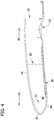
- FIGs 3 and 4 are schematic illustrations of nacelle assembly 12.
- nacelle assembly 12 is generally annular and defines an opening 32 sized and configured to channel air through nacelle assembly 12.
- Nacelle assembly 12 has a diameter 34 at forward end 33 measured with respect to an inner surface 43 that is smaller than a maximum diameter 36 of an outer surface of nacelle assembly 12.
- Nacelle assembly 12 includes an inner barrel 38 and an outer structure 40.
- outer structure 40 is fabricated from a continuous fiber reinforced thermoplastic material.
- outer structure 40 may be fabricated from a continuous fiber reinforced thermoset material.
- outer structure 40 incorporates an integral surfacing film to facilitate protecting nacelle assembly 12 from lighting strikes.
- Outer structure 40 includes a highlight 42 that is defined by forward end 33 of outer structure 40, an outer aft section 44 that is defined by highlight 42, and an inner aft section 46 that is defined by highlight 42.
- Outer aft section 44 includes a point 45 on an outer surface 47 defined by the maximum diameter 36 of nacelle assembly 12.
- outer structure 40 is coupled to a hoop frame (not shown) at an aft end 35 of outer aft section 44 proximate to a fan cowl 54, such that the hoop frame facilitates coupling outer structure 40 to fan cowl 54.
- inner aft section 46 includes a first flange 48 that is used to couple outer structure 40 to inner barrel 38.
- outer structure 40 includes a second flange 50 that is used to couple outer structure 40 to a fan case 53.
- nacelle assembly 12 includes a plurality of bulkheads 57, 58, and 59 that facilitate structurally supporting nacelle assembly 12.
- Bulkheads 57, 58, and 59 also facilitate absorbing any aftward forces induced to outer surface 47 of outer structure 40, such as may be created during a bird-strike for example.
- bulkhead 57 is coupled to outer aft section 44 and inner aft section 46
- bulkhead 58 is coupled to outer aft section 44 and inner barrel 38
- bulkhead 59 is coupled to outer aft section 44 and fan case 53.
- bulkhead 59 is coupled to an aft end 35 of outer aft section 44 such that bulkhead 59 facilitates coupling outer structure 40 to fan cowl 54.
- Bulkheads 57, 58, and 59 may be coupled through a plurality of coupling processes such as through a mechanical fastening process, a thermoplastic welding process, and an adhesive bonding process.
- FIG. 5 is a schematic illustration of outer structure 40.
- outer structure 40 includes at least one stiffener 56 that is oriented either circumferentially and/or longitudinally to facilitate structurally supporting outer aft section 44.
- stiffener 56 is an independent component that is coupled to inner surface 43 of outer structure 40 via, for example, thermoplastic welding and/or an adhesive bonding.
- stiffener 56 may be formed integrally with outer structure 40.
- nacelle assembly 12 includes a structural foam 60 that is oriented and positioned to facilitate absorbing any aftward forces induced to outer surface 47 of outer structure 40, such as may be created during a bird-strike for example.
- structural foam 60 is coupled downstream 35 from highlight 42, against inner surface 43 of outer structure 40 using at least one of a thermoplastic welding process and an adhesive bonding process.
- Outer structure 40 defines an aerodynamic surface over outer surface 47 and facilitates maintaining laminar flow over outer surface 47 from highlight 42 to point 45 defined by maximum diameter 36. Outer surface 47 facilitates reducing drag and improving aerodynamics and fuel efficiency. Moreover, outer structure 40 facilitates reducing assembly time and a number of components of nacelle assembly 12 as compared to known nacelle assemblies, thereby facilitating reducing manufacturing costs and improving manufacturing cycle time. The part count reduction and the use of advanced materials, such as thermoplastic or graphite, facilitate a weight reduction for nacelle assembly 12 as compared to known nacelle assemblies.
- the methods, apparatus, and systems described herein for an integrated inlet design are not limited to the specific embodiments described herein.
- the integrated inlet design described herein provides a more aerodynamic design that facilitates reducing drag and increasing fuel efficiency.
- Practice of the methods, apparatus, or systems described or illustrated herein is not limited to nacelle assemblies. Rather, the methods, apparatus, and systems described or illustrated herein may be utilized independently and separately from other components and/or steps described herein.
Landscapes
- Engineering & Computer Science (AREA)
- Chemical & Material Sciences (AREA)
- Combustion & Propulsion (AREA)
- Aviation & Aerospace Engineering (AREA)
- Mechanical Engineering (AREA)
- General Engineering & Computer Science (AREA)
- Wind Motors (AREA)
- Structures Of Non-Positive Displacement Pumps (AREA)
Description
- This invention relates generally to gas turbine engine nacelle assemblies and, more particularly, to methods and apparatus for an integrated inlet design for a nacelle assembly.
- Some known nacelle assemblies used with turbine engines include a plurality of components that disrupt aerodynamic flow of the nacelle assembly with a plurality of circumferential and axial gaps and steps defined between the components. For example, at least one known nacelle assembly includes an inlet lip, an inlet outer barrel, and a fan cowl that define an outer flow surface of the nacelle assembly. Moreover, within some nacelle assemblies, some known components include a plurality of segments, which define additional gaps and steps on the outer flow surface. For example, at least one known nacelle assembly used in a large high-bypass engine includes an inlet lip defined by a plurality of radial segments.
- Within some turbine engines, at least some of the components and at least some segments of the components used in the nacelle assembly are coupled in position within the nacelle assembly with a plurality of mechanical fasteners. For example, mechanical fasteners may secure a bulkhead that is positioned internal to the inlet lip. The mechanical fasteners, because of their orientation, also disrupt aerodynamic flow of the nacelle assembly. More specifically, in the bulkhead example, heads of the mechanical fasteners are exposed on the outer surface of the nacelle assembly and are positioned directly in the outer flow path. In addition to the exposed heads of the mechanical fasteners, other gaps and/or steps in the nacelle assembly may inhibit laminar flow over the outer flow surface of the nacelle assembly, and may increase aerodynamic drag. Operating a turbine engine with increased aerodynamic drag may reduce fuel burn efficiency.
-
FR 2 906 568EP 1 084 951 - In one aspect, a method for assembling a nacelle assembly according to
claim 1 is provided. The method includes providing an outer structure that extends at least between a highlight defined by a forward end of the outer structure and a point defined by a maximum diameter of the nacelle assembly, coupling a structural foam to an inner surface of an outer aft section of the outer structure, and coupling the outer structure to an inner barrel. - In another aspect, a nacelle assembly according to claim 6 is provided. The nacelle assembly includes an inner barrel and an outer structure. The outer structure includes a highlight defined by a forward end of the outer structure, an outer aft section that includes a point defined by a maximum diameter of the nacelle assembly, wherein the nacelle assembly extends at least between the highlight and the point, and a structural foam coupled to an inner surface of the outer aft section, said structural foam configured to structurally support said outer structure (40).
-
-
Figure 1 is a perspective view of an exemplary aircraft; -
Figure 2 is a cross-sectional view of a portion of an exemplary turbine engine that may be used with the aircraft shown inFigure 1 ; -
Figure 3 is a schematic illustration of a nacelle assembly used with the turbine engine shown inFigure 2 ; -
Figure 4 is another schematic illustration of the nacelle assembly shown inFigure 3 ; and -
Figure 5 is a schematic illustration of an outer structure used with the nacelle assembly shown inFigure 3 . - The systems and methods described herein provide an exemplary integrated inlet design that defines an aerodynamic nacelle assembly design. The description should enable one of ordinary skill in the art to make and use the disclosure, and the description describes several embodiments, adaptations, variations, alternatives, and uses of the disclosure, including what is presently believed to be the best mode of carrying out the disclosure. The disclosure is described herein as being applied to a preferred embodiment, namely, an integrated inlet design.
-
Figure 1 is a schematic illustration of anexemplary aircraft 8 that includes at least oneturbine engine 10 used to provide thrust foraircraft 8. In the exemplary embodiment,turbine engine 10 is coupled to awing 11. More specifically,turbine engine 10 is coupled to a wing pylon (not shown) atwing 11. In an alternate embodiment,turbine engine 10 is coupled to atail 13. More specifically,turbine engine 10 is coupled to a fuselage (not shown) attail 13. -
Figure 2 is a cross-sectional view of a portion ofturbine engine 10. In the exemplary embodiment,turbine engine 10 includes afan assembly 16 that is rotatably coupled about alongitudinal centerline axis 32. In the exemplary embodiment,fan assembly 16 is positioned at aforward end 33 ofturbine engine 10. In an alternative embodiment,fan assembly 16 is positioned at anaft end 35 ofturbine engine 10.Fan assembly 16 includes a plurality of rows offan blades 19 positioned within anacelle assembly 12. In one embodiment,nacelle assembly 12 houses various operating components (not shown) ofturbine engine 10. - In the exemplary embodiment,
turbine engine 10 also includes acore engine 17 that is positioned downstream fromfan assembly 16.Core engine 17 includes acompressor 18, acombustor 20, and aturbine 22 that is coupled tocompressor 18 via acore rotor shaft 26. - During operation,
core engine 17 generates combustion gases that are channeled downstream to aturbine 24 which extracts energy from the gases for poweringfan assembly 16 through ashaft 28. -
Figures 3 and4 are schematic illustrations ofnacelle assembly 12. In the exemplary embodiment as shown inFigure 3 ,nacelle assembly 12 is generally annular and defines an opening 32 sized and configured to channel air throughnacelle assembly 12.Nacelle assembly 12 has adiameter 34 atforward end 33 measured with respect to aninner surface 43 that is smaller than amaximum diameter 36 of an outer surface ofnacelle assembly 12. -
Nacelle assembly 12 includes aninner barrel 38 and anouter structure 40. In the exemplary embodiment,outer structure 40 is fabricated from a continuous fiber reinforced thermoplastic material. Alternatively,outer structure 40 may be fabricated from a continuous fiber reinforced thermoset material. In one embodiment,outer structure 40 incorporates an integral surfacing film to facilitate protectingnacelle assembly 12 from lighting strikes. -
Outer structure 40 includes ahighlight 42 that is defined byforward end 33 ofouter structure 40, anouter aft section 44 that is defined byhighlight 42, and aninner aft section 46 that is defined byhighlight 42.Outer aft section 44 includes apoint 45 on anouter surface 47 defined by themaximum diameter 36 ofnacelle assembly 12. In another embodiment,outer structure 40 is coupled to a hoop frame (not shown) at anaft end 35 ofouter aft section 44 proximate to afan cowl 54, such that the hoop frame facilitates couplingouter structure 40 tofan cowl 54. - In the exemplary embodiment as shown in
Figure 4 ,inner aft section 46 includes afirst flange 48 that is used to coupleouter structure 40 toinner barrel 38. In another embodiment,outer structure 40 includes a second flange 50 that is used to coupleouter structure 40 to afan case 53. - In the exemplary embodiment,
nacelle assembly 12 includes a plurality ofbulkheads nacelle assembly 12. Bulkheads 57, 58, and 59 also facilitate absorbing any aftward forces induced toouter surface 47 ofouter structure 40, such as may be created during a bird-strike for example. In the exemplary embodiment,bulkhead 57 is coupled toouter aft section 44 andinner aft section 46,bulkhead 58 is coupled toouter aft section 44 andinner barrel 38, andbulkhead 59 is coupled toouter aft section 44 andfan case 53. In the exemplary embodiment,bulkhead 59 is coupled to anaft end 35 ofouter aft section 44 such thatbulkhead 59 facilitates couplingouter structure 40 tofan cowl 54. Bulkheads 57, 58, and 59 may be coupled through a plurality of coupling processes such as through a mechanical fastening process, a thermoplastic welding process, and an adhesive bonding process. -
Figure 5 is a schematic illustration ofouter structure 40. In the exemplary embodiment,outer structure 40 includes at least onestiffener 56 that is oriented either circumferentially and/or longitudinally to facilitate structurally supportingouter aft section 44. In the exemplary embodiment,stiffener 56 is an independent component that is coupled toinner surface 43 ofouter structure 40 via, for example, thermoplastic welding and/or an adhesive bonding. In an alternate embodiment,stiffener 56 may be formed integrally withouter structure 40. - In the exemplary embodiment,
nacelle assembly 12 includes astructural foam 60 that is oriented and positioned to facilitate absorbing any aftward forces induced toouter surface 47 ofouter structure 40, such as may be created during a bird-strike for example. In the exemplary embodiment,structural foam 60 is coupled downstream 35 fromhighlight 42, againstinner surface 43 ofouter structure 40 using at least one of a thermoplastic welding process and an adhesive bonding process. - During operation, air flows from
forward end 33 toaft end 35 ofnacelle assembly 12.Outer structure 40 defines an aerodynamic surface overouter surface 47 and facilitates maintaining laminar flow overouter surface 47 fromhighlight 42 to point 45 defined bymaximum diameter 36.Outer surface 47 facilitates reducing drag and improving aerodynamics and fuel efficiency. Moreover,outer structure 40 facilitates reducing assembly time and a number of components ofnacelle assembly 12 as compared to known nacelle assemblies, thereby facilitating reducing manufacturing costs and improving manufacturing cycle time. The part count reduction and the use of advanced materials, such as thermoplastic or graphite, facilitate a weight reduction fornacelle assembly 12 as compared to known nacelle assemblies. - The methods, apparatus, and systems described herein for an integrated inlet design are not limited to the specific embodiments described herein. The integrated inlet design described herein provides a more aerodynamic design that facilitates reducing drag and increasing fuel efficiency. Practice of the methods, apparatus, or systems described or illustrated herein is not limited to nacelle assemblies. Rather, the methods, apparatus, and systems described or illustrated herein may be utilized independently and separately from other components and/or steps described herein.
- The written description uses examples to disclose the invention, including the best mode, and also to enable any person skilled in the art to practice the invention, including making and using any devices or systems and performing any incorporated methods. The patentable scope of the invention is defined by the claims and may include other examples that occur to those skilled in the art. Such other examples are intended to be within the scope of the claims if they have structural elements that do not differ from the literal language of the claims, or if they include equivalent structural elements with insubstantial differences from the literal languages of the claims.
- While the invention has been described in terms of various specific embodiments, those skilled in the art will recognize that the invention can be practiced with modification within the scope of the claims.
Claims (10)
- A method for assembling a nacelle assembly (12), said method comprising:providing an outer structure (40) that extends at least between a highlight (42) defined by a forward end (33) of the outer structure (40) and a point (45) defined by a maximum diameter (36) of the nacelle assembly (12);coupling a structural foam (60) to an inner surface of an outer aft section (44) of the outer structure (40), the structural foam being oriented and positioned to facilitate absorbing any aftward forces induced to an outer surface (47) of the outer structure (40);coupling the outer structure (40) to an inner barrel (38) and a fan case (53);providing a stiffener (56) coupled to the inner surface of the outer aft section (44), the stiffener (56) being oriented either circumferentially and/or longitudinally to facilitate structurally supporting the outer aft section (44);providing a first bulkhead (58) coupled to and extending between the outer aft section (44) and the inner barrel (38);providing a second bulkhead (57) coupled to and extending between the outer aft section (44) and an inner aft section (46) of the outer structure (40); andproviding a third bulkhead (59) coupled to and extending between the outer aft section (44) and the fan case (53),wherein the first, second and third bulkheads (57, 58, 59) are configured to facilitate absorbing any aftward forces induced to the outer surface (47) of the outer structure (40).
- A method for assembling a nacelle assembly (12) in accordance with claim 1, wherein the outer structure (40) is fabricated from at least one of a continuous fiber reinforced thermoplastic material and a continuous fiber reinforced thermoset material.
- A method for assembling a nacelle assembly (12) in accordance with claim 1, wherein the outer structure (40) includes a first flange (48) that is positioned at an inner aft section of the outer structure (40), wherein the first flange (48) is configured to couple the outer structure (40) to the inner barrel (38).
- A method for assembling a nacelle assembly (12) in accordance with claim 1, wherein the outer structure (40) includes a second flange (50) that is positioned at an inner aft section of the outer structure (40), wherein the second flange (50) is configured to couple to the outer structure (40) to the fan case (53).
- A method for assembling a nacelle assembly (12) in accordance with claim 1, wherein
at least one of the stiffener (56) and the bulkheads (57, 58, 59) is coupled to an inner surface of the outer aft section (44) via at least one of thermoplastic welding and adhesive bonding. - A nacelle assembly (12) comprising an inner barrel (38), a fan case (53) and an outer structure (40), the outer structure (40) being coupled to the inner barrel (38) and the fan case (53), said outer structure (40) comprising:a highlight (42) defined by a forward end of said outer structure (40); andan outer aft section (44) that includes a point (45) defined by a maximum diameter (36) of said nacelle assembly (12), wherein said nacelle assembly (12) extends at least between said highlight (42) and said point (45);a structural foam (60) coupled to an inner surface of the outer aft section (44), said structural foam (60) being oriented and positioned to facilitate absorbing any aftward forces induced to the outer surface (47) of the outer structure (40);characterized in that said outer structure (40) further comprises:a stiffener (56) coupled to the inner surface of the outer aft section (44), the stiffener (56) being oriented either circumferentially and/or longitudinally to facilitate structurally supporting the outer aft section (44);a first bulkhead (58) coupled to and extending between the outer aft section (44) and the inner barrel (38);a second bulkhead (57) coupled to and extending between the outer aft section (44) and an inner aft section (46) of the outer structure (40); anda third bulkhead (59) coupled to and extending between the outer aft section (44) and the fan case (53),wherein the first, second and third bulkheads (57, 58, 59) are configured to facilitate absorbing any aftward forces induced to the outer surface (47) of the outer structure (40).
- A nacelle assembly (12) in accordance with claim 6, wherein said outer structure (40) is fabricated from at least one of a continuous fiber reinforced thermoplastic material and a continuous fiber reinforced thermoset material.
- A nacelle assembly (12) in accordance with claim 6, further comprising a first flange (48) that is positioned at the inner aft section (46) of said outer structure (40), said first flange (48) configured to couple said outer structure (40) to the inner barrel (38).
- A nacelle assembly (12) in accordance with claim 6, further comprising a second flange (50) that is positioned at the inner aft section (46) of said outer structure (40), said second flange (50) configured to couple said outer structure (40) to the fan case (53).
- A nacelle assembly (12) in accordance with claim 6, wherein at least one of the stiffener (56) and the bulkheads (57, 58, 59) is coupled to an inner surface of said outer aft section (44) via at least one of thermoplastic welding and adhesive bonding.
Applications Claiming Priority (2)
| Application Number | Priority Date | Filing Date | Title |
|---|---|---|---|
| US12/274,038 US8152461B2 (en) | 2008-11-19 | 2008-11-19 | Integrated inlet design |
| PCT/US2009/059996 WO2010059301A2 (en) | 2008-11-19 | 2009-10-08 | Integrated inlet design |
Publications (2)
| Publication Number | Publication Date |
|---|---|
| EP2346736A2 EP2346736A2 (en) | 2011-07-27 |
| EP2346736B1 true EP2346736B1 (en) | 2020-11-25 |
Family
ID=42172193
Family Applications (1)
| Application Number | Title | Priority Date | Filing Date |
|---|---|---|---|
| EP09741092.2A Active EP2346736B1 (en) | 2008-11-19 | 2009-10-08 | Integrated inlet design |
Country Status (5)
| Country | Link |
|---|---|
| US (1) | US8152461B2 (en) |
| EP (1) | EP2346736B1 (en) |
| JP (1) | JP2012509440A (en) |
| CA (1) | CA2742834C (en) |
| WO (1) | WO2010059301A2 (en) |
Families Citing this family (17)
| Publication number | Priority date | Publication date | Assignee | Title |
|---|---|---|---|---|
| US8197191B2 (en) * | 2009-04-14 | 2012-06-12 | Rohr, Inc. | Inlet section of an aircraft engine nacelle |
| US8382039B2 (en) * | 2009-12-30 | 2013-02-26 | MRA Systems Inc. | Turbomachine nacelle and anti-icing system and method therefor |
| GB201202790D0 (en) * | 2012-02-20 | 2012-04-04 | Rolls Royce Plc | An aircraft propulsion system |
| US9168716B2 (en) * | 2012-09-14 | 2015-10-27 | The Boeing Company | Metallic sandwich structure having small bend radius |
| FR2987601A1 (en) * | 2012-09-20 | 2013-09-06 | Aircelle Sa | Laminar nacelle for turbojet of aircraft, has external panel associated with connection support that presents dismountable end of fastener and another dismountable end of fastener that is intended to be directly attached to casing of blower |
| US20140186166A1 (en) * | 2012-12-27 | 2014-07-03 | General Electric Company | Hybrid Continuous Fiber Chopped Fiber Polymer Composite Structure |
| ITFI20130100A1 (en) * | 2013-05-03 | 2014-11-04 | Nuovo Pignone Srl | "COMPOSITE MATERIAL INLET PLENUM AND GAS TURBINE ENGINE SYSTEM COMPRISING SAID PLENUM" |
| US9664113B2 (en) * | 2014-03-15 | 2017-05-30 | The Boeing Company | One piece inlet lip skin design |
| US9725190B2 (en) * | 2015-02-13 | 2017-08-08 | The Boeing Company | Aircraft engine inlet assembly apparatus |
| US10160552B2 (en) | 2016-02-12 | 2018-12-25 | Rohr, Inc. | Inlet assembly for a turbofan engine |
| US11125157B2 (en) * | 2017-09-22 | 2021-09-21 | The Boeing Company | Advanced inlet design |
| FR3075761A1 (en) * | 2017-12-21 | 2019-06-28 | Airbus Operations | ANTERIOR PLATFORM PART OF A NACELLE COMPRISING AN INCLINE RIGIDIFICATION FRAME |
| US11946413B2 (en) * | 2019-07-29 | 2024-04-02 | The Boeing Company | Inlet bulkheads for large diameter aircraft engines |
| FR3099915A1 (en) * | 2019-08-13 | 2021-02-19 | Airbus Operations | Front part of the nacelle of an aircraft propulsion unit, the air inlet lip of which is linked to the outer panel by interlocking |
| EP3945033B1 (en) * | 2020-07-27 | 2022-09-07 | Airbus Operations (S.A.S.) | Aircraft propulsion unit |
| FR3115223B1 (en) * | 2020-10-21 | 2023-05-12 | Safran Nacelles | Manufacture of an air inlet lip or an annular sector of an air inlet lip incorporating openings with a recessed edge |
| BR102022003769A2 (en) | 2021-05-04 | 2022-11-16 | The Boeing Company | NACELE ENTRY STRUCTURE OF AN ENGINE ASSEMBLY |
Family Cites Families (14)
| Publication number | Priority date | Publication date | Assignee | Title |
|---|---|---|---|---|
| US3871844A (en) * | 1973-09-28 | 1975-03-18 | Sr Frank F Calvin | Screen apparatus for air inlet |
| US5259724A (en) * | 1992-05-01 | 1993-11-09 | General Electric Company | Inlet fan blade fragment containment shield |
| FR2757823B1 (en) * | 1996-12-26 | 1999-03-12 | Aerospatiale | LAMINARY FLOW TURBOREACTOR BASKET |
| US5931422A (en) * | 1997-06-09 | 1999-08-03 | Mcdonnell Douglas | Active reinforced elastomer system |
| US6089505A (en) * | 1997-07-22 | 2000-07-18 | Mcdonnell Douglas Corporation | Mission adaptive inlet |
| GB9921935D0 (en) | 1999-09-17 | 1999-11-17 | Rolls Royce | A nacelle assembly for a gas turbine engine |
| US7588212B2 (en) * | 2003-07-08 | 2009-09-15 | Rohr Inc. | Method and apparatus for noise abatement and ice protection of an aircraft engine nacelle inlet lip |
| EP1780382A3 (en) * | 2003-07-29 | 2011-03-09 | Pratt & Whitney Canada Corp. | Turbofan case and method of making |
| US7370467B2 (en) * | 2003-07-29 | 2008-05-13 | Pratt & Whitney Canada Corp. | Turbofan case and method of making |
| FR2868123B1 (en) * | 2004-03-29 | 2006-06-23 | Airbus France Sas | AIR INTAKE STRUCTURE FOR AN AIRCRAFT ENGINE |
| US20060032983A1 (en) * | 2004-07-19 | 2006-02-16 | Brand Joseph H | Foreign object damage tolerant nacelle anti-icing system |
| US7923668B2 (en) | 2006-02-24 | 2011-04-12 | Rohr, Inc. | Acoustic nacelle inlet lip having composite construction and an integral electric ice protection heater disposed therein |
| FR2906568B1 (en) | 2006-10-02 | 2012-01-06 | Aircelle Sa | DEPOSITABLE AIR INTAKE STRUCTURE FOR TURBOJET NACELLE. |
| US8092169B2 (en) * | 2008-09-16 | 2012-01-10 | United Technologies Corporation | Integrated inlet fan case |
-
2008
- 2008-11-19 US US12/274,038 patent/US8152461B2/en active Active
-
2009
- 2009-10-08 EP EP09741092.2A patent/EP2346736B1/en active Active
- 2009-10-08 WO PCT/US2009/059996 patent/WO2010059301A2/en active Application Filing
- 2009-10-08 JP JP2011537450A patent/JP2012509440A/en active Pending
- 2009-10-08 CA CA2742834A patent/CA2742834C/en active Active
Non-Patent Citations (1)
| Title |
|---|
| None * |
Also Published As
| Publication number | Publication date |
|---|---|
| US8152461B2 (en) | 2012-04-10 |
| CA2742834A1 (en) | 2010-05-27 |
| EP2346736A2 (en) | 2011-07-27 |
| JP2012509440A (en) | 2012-04-19 |
| WO2010059301A3 (en) | 2010-07-22 |
| US20100124494A1 (en) | 2010-05-20 |
| WO2010059301A2 (en) | 2010-05-27 |
| CA2742834C (en) | 2017-03-28 |
Similar Documents
| Publication | Publication Date | Title |
|---|---|---|
| EP2346736B1 (en) | Integrated inlet design | |
| US20080159856A1 (en) | Guide vane and method of fabricating the same | |
| EP1942253A2 (en) | Guide vane and method of fabricating the same | |
| US9194330B2 (en) | Retrofitable auxiliary inlet scoop | |
| US9103298B2 (en) | Seal for a variable area fan nozzle | |
| US9745851B2 (en) | Metal leading edge on composite blade airfoil and shank | |
| US10160552B2 (en) | Inlet assembly for a turbofan engine | |
| US20180334249A1 (en) | Strake for aircraft propulsion system nacelle | |
| EP2971660B1 (en) | Thermally conforming acoustic liner cartridge for a gas turbine engine | |
| US10502161B2 (en) | Cascade system and apparatus | |
| US11548652B2 (en) | Nacelle | |
| US20240309769A1 (en) | Outlet guide vane assembly for a turbofan engine | |
| CA2752272C (en) | Rotor assembly | |
| EP3628589B1 (en) | Active laminar flow control structural plenums fastened | |
| US9856742B2 (en) | Sealing system for variable area fan nozzle | |
| US10767596B2 (en) | Nacelle | |
| US20240209748A1 (en) | Outlet guide vane assembly for a turbofan engine |
Legal Events
| Date | Code | Title | Description |
|---|---|---|---|
| PUAI | Public reference made under article 153(3) epc to a published international application that has entered the european phase |
Free format text: ORIGINAL CODE: 0009012 |
|
| 17P | Request for examination filed |
Effective date: 20110620 |
|
| AK | Designated contracting states |
Kind code of ref document: A2 Designated state(s): AT BE BG CH CY CZ DE DK EE ES FI FR GB GR HR HU IE IS IT LI LT LU LV MC MK MT NL NO PL PT RO SE SI SK SM TR |
|
| AX | Request for extension of the european patent |
Extension state: AL BA RS |
|
| DAX | Request for extension of the european patent (deleted) | ||
| STAA | Information on the status of an ep patent application or granted ep patent |
Free format text: STATUS: EXAMINATION IS IN PROGRESS |
|
| 17Q | First examination report despatched |
Effective date: 20180712 |
|
| GRAP | Despatch of communication of intention to grant a patent |
Free format text: ORIGINAL CODE: EPIDOSNIGR1 |
|
| STAA | Information on the status of an ep patent application or granted ep patent |
Free format text: STATUS: GRANT OF PATENT IS INTENDED |
|
| INTG | Intention to grant announced |
Effective date: 20200214 |
|
| GRAJ | Information related to disapproval of communication of intention to grant by the applicant or resumption of examination proceedings by the epo deleted |
Free format text: ORIGINAL CODE: EPIDOSDIGR1 |
|
| STAA | Information on the status of an ep patent application or granted ep patent |
Free format text: STATUS: EXAMINATION IS IN PROGRESS |
|
| GRAP | Despatch of communication of intention to grant a patent |
Free format text: ORIGINAL CODE: EPIDOSNIGR1 |
|
| STAA | Information on the status of an ep patent application or granted ep patent |
Free format text: STATUS: GRANT OF PATENT IS INTENDED |
|
| INTC | Intention to grant announced (deleted) | ||
| INTG | Intention to grant announced |
Effective date: 20200623 |
|
| GRAS | Grant fee paid |
Free format text: ORIGINAL CODE: EPIDOSNIGR3 |
|
| GRAA | (expected) grant |
Free format text: ORIGINAL CODE: 0009210 |
|
| STAA | Information on the status of an ep patent application or granted ep patent |
Free format text: STATUS: THE PATENT HAS BEEN GRANTED |
|
| AK | Designated contracting states |
Kind code of ref document: B1 Designated state(s): AT BE BG CH CY CZ DE DK EE ES FI FR GB GR HR HU IE IS IT LI LT LU LV MC MK MT NL NO PL PT RO SE SI SK SM TR |
|
| REG | Reference to a national code |
Ref country code: GB Ref legal event code: FG4D |
|
| REG | Reference to a national code |
Ref country code: CH Ref legal event code: EP |
|
| REG | Reference to a national code |
Ref country code: DE Ref legal event code: R096 Ref document number: 602009063096 Country of ref document: DE |
|
| REG | Reference to a national code |
Ref country code: AT Ref legal event code: REF Ref document number: 1338011 Country of ref document: AT Kind code of ref document: T Effective date: 20201215 |
|
| REG | Reference to a national code |
Ref country code: IE Ref legal event code: FG4D |
|
| REG | Reference to a national code |
Ref country code: AT Ref legal event code: MK05 Ref document number: 1338011 Country of ref document: AT Kind code of ref document: T Effective date: 20201125 |
|
| REG | Reference to a national code |
Ref country code: NL Ref legal event code: MP Effective date: 20201125 |
|
| PG25 | Lapsed in a contracting state [announced via postgrant information from national office to epo] |
Ref country code: GR Free format text: LAPSE BECAUSE OF FAILURE TO SUBMIT A TRANSLATION OF THE DESCRIPTION OR TO PAY THE FEE WITHIN THE PRESCRIBED TIME-LIMIT Effective date: 20210226 Ref country code: NO Free format text: LAPSE BECAUSE OF FAILURE TO SUBMIT A TRANSLATION OF THE DESCRIPTION OR TO PAY THE FEE WITHIN THE PRESCRIBED TIME-LIMIT Effective date: 20210225 Ref country code: PT Free format text: LAPSE BECAUSE OF FAILURE TO SUBMIT A TRANSLATION OF THE DESCRIPTION OR TO PAY THE FEE WITHIN THE PRESCRIBED TIME-LIMIT Effective date: 20210325 Ref country code: FI Free format text: LAPSE BECAUSE OF FAILURE TO SUBMIT A TRANSLATION OF THE DESCRIPTION OR TO PAY THE FEE WITHIN THE PRESCRIBED TIME-LIMIT Effective date: 20201125 |
|
| PG25 | Lapsed in a contracting state [announced via postgrant information from national office to epo] |
Ref country code: AT Free format text: LAPSE BECAUSE OF FAILURE TO SUBMIT A TRANSLATION OF THE DESCRIPTION OR TO PAY THE FEE WITHIN THE PRESCRIBED TIME-LIMIT Effective date: 20201125 Ref country code: BG Free format text: LAPSE BECAUSE OF FAILURE TO SUBMIT A TRANSLATION OF THE DESCRIPTION OR TO PAY THE FEE WITHIN THE PRESCRIBED TIME-LIMIT Effective date: 20210225 Ref country code: IS Free format text: LAPSE BECAUSE OF FAILURE TO SUBMIT A TRANSLATION OF THE DESCRIPTION OR TO PAY THE FEE WITHIN THE PRESCRIBED TIME-LIMIT Effective date: 20210325 Ref country code: SE Free format text: LAPSE BECAUSE OF FAILURE TO SUBMIT A TRANSLATION OF THE DESCRIPTION OR TO PAY THE FEE WITHIN THE PRESCRIBED TIME-LIMIT Effective date: 20201125 Ref country code: PL Free format text: LAPSE BECAUSE OF FAILURE TO SUBMIT A TRANSLATION OF THE DESCRIPTION OR TO PAY THE FEE WITHIN THE PRESCRIBED TIME-LIMIT Effective date: 20201125 Ref country code: LV Free format text: LAPSE BECAUSE OF FAILURE TO SUBMIT A TRANSLATION OF THE DESCRIPTION OR TO PAY THE FEE WITHIN THE PRESCRIBED TIME-LIMIT Effective date: 20201125 |
|
| REG | Reference to a national code |
Ref country code: LT Ref legal event code: MG9D |
|
| PG25 | Lapsed in a contracting state [announced via postgrant information from national office to epo] |
Ref country code: HR Free format text: LAPSE BECAUSE OF FAILURE TO SUBMIT A TRANSLATION OF THE DESCRIPTION OR TO PAY THE FEE WITHIN THE PRESCRIBED TIME-LIMIT Effective date: 20201125 |
|
| PG25 | Lapsed in a contracting state [announced via postgrant information from national office to epo] |
Ref country code: LT Free format text: LAPSE BECAUSE OF FAILURE TO SUBMIT A TRANSLATION OF THE DESCRIPTION OR TO PAY THE FEE WITHIN THE PRESCRIBED TIME-LIMIT Effective date: 20201125 Ref country code: EE Free format text: LAPSE BECAUSE OF FAILURE TO SUBMIT A TRANSLATION OF THE DESCRIPTION OR TO PAY THE FEE WITHIN THE PRESCRIBED TIME-LIMIT Effective date: 20201125 Ref country code: CZ Free format text: LAPSE BECAUSE OF FAILURE TO SUBMIT A TRANSLATION OF THE DESCRIPTION OR TO PAY THE FEE WITHIN THE PRESCRIBED TIME-LIMIT Effective date: 20201125 Ref country code: RO Free format text: LAPSE BECAUSE OF FAILURE TO SUBMIT A TRANSLATION OF THE DESCRIPTION OR TO PAY THE FEE WITHIN THE PRESCRIBED TIME-LIMIT Effective date: 20201125 Ref country code: SK Free format text: LAPSE BECAUSE OF FAILURE TO SUBMIT A TRANSLATION OF THE DESCRIPTION OR TO PAY THE FEE WITHIN THE PRESCRIBED TIME-LIMIT Effective date: 20201125 Ref country code: SM Free format text: LAPSE BECAUSE OF FAILURE TO SUBMIT A TRANSLATION OF THE DESCRIPTION OR TO PAY THE FEE WITHIN THE PRESCRIBED TIME-LIMIT Effective date: 20201125 |
|
| REG | Reference to a national code |
Ref country code: DE Ref legal event code: R097 Ref document number: 602009063096 Country of ref document: DE |
|
| PG25 | Lapsed in a contracting state [announced via postgrant information from national office to epo] |
Ref country code: DK Free format text: LAPSE BECAUSE OF FAILURE TO SUBMIT A TRANSLATION OF THE DESCRIPTION OR TO PAY THE FEE WITHIN THE PRESCRIBED TIME-LIMIT Effective date: 20201125 |
|
| PLBE | No opposition filed within time limit |
Free format text: ORIGINAL CODE: 0009261 |
|
| STAA | Information on the status of an ep patent application or granted ep patent |
Free format text: STATUS: NO OPPOSITION FILED WITHIN TIME LIMIT |
|
| PG25 | Lapsed in a contracting state [announced via postgrant information from national office to epo] |
Ref country code: NL Free format text: LAPSE BECAUSE OF FAILURE TO SUBMIT A TRANSLATION OF THE DESCRIPTION OR TO PAY THE FEE WITHIN THE PRESCRIBED TIME-LIMIT Effective date: 20201125 Ref country code: IT Free format text: LAPSE BECAUSE OF FAILURE TO SUBMIT A TRANSLATION OF THE DESCRIPTION OR TO PAY THE FEE WITHIN THE PRESCRIBED TIME-LIMIT Effective date: 20201125 |
|
| 26N | No opposition filed |
Effective date: 20210826 |
|
| PG25 | Lapsed in a contracting state [announced via postgrant information from national office to epo] |
Ref country code: ES Free format text: LAPSE BECAUSE OF FAILURE TO SUBMIT A TRANSLATION OF THE DESCRIPTION OR TO PAY THE FEE WITHIN THE PRESCRIBED TIME-LIMIT Effective date: 20201125 Ref country code: SI Free format text: LAPSE BECAUSE OF FAILURE TO SUBMIT A TRANSLATION OF THE DESCRIPTION OR TO PAY THE FEE WITHIN THE PRESCRIBED TIME-LIMIT Effective date: 20201125 |
|
| REG | Reference to a national code |
Ref country code: DE Ref legal event code: R119 Ref document number: 602009063096 Country of ref document: DE |
|
| REG | Reference to a national code |
Ref country code: CH Ref legal event code: PL |
|
| PG25 | Lapsed in a contracting state [announced via postgrant information from national office to epo] |
Ref country code: IS Free format text: LAPSE BECAUSE OF FAILURE TO SUBMIT A TRANSLATION OF THE DESCRIPTION OR TO PAY THE FEE WITHIN THE PRESCRIBED TIME-LIMIT Effective date: 20210325 |
|
| REG | Reference to a national code |
Ref country code: BE Ref legal event code: MM Effective date: 20211031 |
|
| GBPC | Gb: european patent ceased through non-payment of renewal fee |
Effective date: 20211008 |
|
| PG25 | Lapsed in a contracting state [announced via postgrant information from national office to epo] |
Ref country code: MC Free format text: LAPSE BECAUSE OF FAILURE TO SUBMIT A TRANSLATION OF THE DESCRIPTION OR TO PAY THE FEE WITHIN THE PRESCRIBED TIME-LIMIT Effective date: 20201125 |
|
| PG25 | Lapsed in a contracting state [announced via postgrant information from national office to epo] |
Ref country code: LU Free format text: LAPSE BECAUSE OF NON-PAYMENT OF DUE FEES Effective date: 20211008 Ref country code: GB Free format text: LAPSE BECAUSE OF NON-PAYMENT OF DUE FEES Effective date: 20211008 Ref country code: DE Free format text: LAPSE BECAUSE OF NON-PAYMENT OF DUE FEES Effective date: 20220503 Ref country code: BE Free format text: LAPSE BECAUSE OF NON-PAYMENT OF DUE FEES Effective date: 20211031 |
|
| PG25 | Lapsed in a contracting state [announced via postgrant information from national office to epo] |
Ref country code: LI Free format text: LAPSE BECAUSE OF NON-PAYMENT OF DUE FEES Effective date: 20211031 Ref country code: CH Free format text: LAPSE BECAUSE OF NON-PAYMENT OF DUE FEES Effective date: 20211031 |
|
| PG25 | Lapsed in a contracting state [announced via postgrant information from national office to epo] |
Ref country code: IE Free format text: LAPSE BECAUSE OF NON-PAYMENT OF DUE FEES Effective date: 20211008 |
|
| PG25 | Lapsed in a contracting state [announced via postgrant information from national office to epo] |
Ref country code: HU Free format text: LAPSE BECAUSE OF FAILURE TO SUBMIT A TRANSLATION OF THE DESCRIPTION OR TO PAY THE FEE WITHIN THE PRESCRIBED TIME-LIMIT; INVALID AB INITIO Effective date: 20091008 Ref country code: CY Free format text: LAPSE BECAUSE OF FAILURE TO SUBMIT A TRANSLATION OF THE DESCRIPTION OR TO PAY THE FEE WITHIN THE PRESCRIBED TIME-LIMIT Effective date: 20201125 |
|
| PGFP | Annual fee paid to national office [announced via postgrant information from national office to epo] |
Ref country code: FR Payment date: 20230920 Year of fee payment: 15 |
|
| PG25 | Lapsed in a contracting state [announced via postgrant information from national office to epo] |
Ref country code: MK Free format text: LAPSE BECAUSE OF FAILURE TO SUBMIT A TRANSLATION OF THE DESCRIPTION OR TO PAY THE FEE WITHIN THE PRESCRIBED TIME-LIMIT Effective date: 20201125 |
|
| PG25 | Lapsed in a contracting state [announced via postgrant information from national office to epo] |
Ref country code: TR Free format text: LAPSE BECAUSE OF FAILURE TO SUBMIT A TRANSLATION OF THE DESCRIPTION OR TO PAY THE FEE WITHIN THE PRESCRIBED TIME-LIMIT Effective date: 20201125 |