EP3404214A1 - Blade outer air seal assembly and gas turbine engine with such an assembly - Google Patents
Blade outer air seal assembly and gas turbine engine with such an assembly Download PDFInfo
- Publication number
- EP3404214A1 EP3404214A1 EP18170407.3A EP18170407A EP3404214A1 EP 3404214 A1 EP3404214 A1 EP 3404214A1 EP 18170407 A EP18170407 A EP 18170407A EP 3404214 A1 EP3404214 A1 EP 3404214A1
- Authority
- EP
- European Patent Office
- Prior art keywords
- boas
- shroud
- aft
- facing
- face
- Prior art date
- Legal status (The legal status is an assumption and is not a legal conclusion. Google has not performed a legal analysis and makes no representation as to the accuracy of the status listed.)
- Granted
Links
- 239000012530 fluid Substances 0.000 claims abstract description 18
- PXHVJJICTQNCMI-UHFFFAOYSA-N Nickel Chemical compound [Ni] PXHVJJICTQNCMI-UHFFFAOYSA-N 0.000 claims description 20
- 229910052759 nickel Inorganic materials 0.000 claims description 10
- 229910045601 alloy Inorganic materials 0.000 claims description 8
- 239000000956 alloy Substances 0.000 claims description 8
- 229910000531 Co alloy Inorganic materials 0.000 claims description 6
- 239000000446 fuel Substances 0.000 claims description 6
- 230000004323 axial length Effects 0.000 claims description 4
- 238000000926 separation method Methods 0.000 claims description 4
- 239000007789 gas Substances 0.000 description 22
- 238000000034 method Methods 0.000 description 9
- 230000008901 benefit Effects 0.000 description 7
- 230000004044 response Effects 0.000 description 5
- 239000000463 material Substances 0.000 description 4
- 230000008569 process Effects 0.000 description 3
- 239000010941 cobalt Substances 0.000 description 2
- 229910017052 cobalt Inorganic materials 0.000 description 2
- GUTLYIVDDKVIGB-UHFFFAOYSA-N cobalt atom Chemical compound [Co] GUTLYIVDDKVIGB-UHFFFAOYSA-N 0.000 description 2
- 230000006835 compression Effects 0.000 description 2
- 238000007906 compression Methods 0.000 description 2
- 239000002826 coolant Substances 0.000 description 2
- 230000003068 static effect Effects 0.000 description 2
- 229910018487 Ni—Cr Inorganic materials 0.000 description 1
- 229910001080 W alloy Inorganic materials 0.000 description 1
- HNYSBSMSUWPWOM-UHFFFAOYSA-N [Ni].[W].[Cr].[Co] Chemical compound [Ni].[W].[Cr].[Co] HNYSBSMSUWPWOM-UHFFFAOYSA-N 0.000 description 1
- XAGFODPZIPBFFR-UHFFFAOYSA-N aluminium Chemical compound [Al] XAGFODPZIPBFFR-UHFFFAOYSA-N 0.000 description 1
- 229910052782 aluminium Inorganic materials 0.000 description 1
- VNNRSPGTAMTISX-UHFFFAOYSA-N chromium nickel Chemical compound [Cr].[Ni] VNNRSPGTAMTISX-UHFFFAOYSA-N 0.000 description 1
- 239000000567 combustion gas Substances 0.000 description 1
- 238000004891 communication Methods 0.000 description 1
- 150000001875 compounds Chemical class 0.000 description 1
- 230000001143 conditioned effect Effects 0.000 description 1
- 230000003750 conditioning effect Effects 0.000 description 1
- 230000008878 coupling Effects 0.000 description 1
- 238000010168 coupling process Methods 0.000 description 1
- 238000005859 coupling reaction Methods 0.000 description 1
- 238000010248 power generation Methods 0.000 description 1
- 230000009467 reduction Effects 0.000 description 1
- 239000000126 substance Substances 0.000 description 1
- 229910000601 superalloy Inorganic materials 0.000 description 1
Images

Classifications
-
- F—MECHANICAL ENGINEERING; LIGHTING; HEATING; WEAPONS; BLASTING
- F01—MACHINES OR ENGINES IN GENERAL; ENGINE PLANTS IN GENERAL; STEAM ENGINES
- F01D—NON-POSITIVE DISPLACEMENT MACHINES OR ENGINES, e.g. STEAM TURBINES
- F01D11/00—Preventing or minimising internal leakage of working-fluid, e.g. between stages
- F01D11/005—Sealing means between non relatively rotating elements
-
- F—MECHANICAL ENGINEERING; LIGHTING; HEATING; WEAPONS; BLASTING
- F01—MACHINES OR ENGINES IN GENERAL; ENGINE PLANTS IN GENERAL; STEAM ENGINES
- F01D—NON-POSITIVE DISPLACEMENT MACHINES OR ENGINES, e.g. STEAM TURBINES
- F01D11/00—Preventing or minimising internal leakage of working-fluid, e.g. between stages
- F01D11/08—Preventing or minimising internal leakage of working-fluid, e.g. between stages for sealing space between rotor blade tips and stator
- F01D11/14—Adjusting or regulating tip-clearance, i.e. distance between rotor-blade tips and stator casing
-
- F—MECHANICAL ENGINEERING; LIGHTING; HEATING; WEAPONS; BLASTING
- F01—MACHINES OR ENGINES IN GENERAL; ENGINE PLANTS IN GENERAL; STEAM ENGINES
- F01D—NON-POSITIVE DISPLACEMENT MACHINES OR ENGINES, e.g. STEAM TURBINES
- F01D11/00—Preventing or minimising internal leakage of working-fluid, e.g. between stages
- F01D11/08—Preventing or minimising internal leakage of working-fluid, e.g. between stages for sealing space between rotor blade tips and stator
- F01D11/14—Adjusting or regulating tip-clearance, i.e. distance between rotor-blade tips and stator casing
- F01D11/16—Adjusting or regulating tip-clearance, i.e. distance between rotor-blade tips and stator casing by self-adjusting means
-
- F—MECHANICAL ENGINEERING; LIGHTING; HEATING; WEAPONS; BLASTING
- F16—ENGINEERING ELEMENTS AND UNITS; GENERAL MEASURES FOR PRODUCING AND MAINTAINING EFFECTIVE FUNCTIONING OF MACHINES OR INSTALLATIONS; THERMAL INSULATION IN GENERAL
- F16J—PISTONS; CYLINDERS; SEALINGS
- F16J15/00—Sealings
- F16J15/02—Sealings between relatively-stationary surfaces
- F16J15/06—Sealings between relatively-stationary surfaces with solid packing compressed between sealing surfaces
- F16J15/08—Sealings between relatively-stationary surfaces with solid packing compressed between sealing surfaces with exclusively metal packing
- F16J15/0887—Sealings between relatively-stationary surfaces with solid packing compressed between sealing surfaces with exclusively metal packing the sealing effect being obtained by elastic deformation of the packing
-
- F—MECHANICAL ENGINEERING; LIGHTING; HEATING; WEAPONS; BLASTING
- F05—INDEXING SCHEMES RELATING TO ENGINES OR PUMPS IN VARIOUS SUBCLASSES OF CLASSES F01-F04
- F05D—INDEXING SCHEME FOR ASPECTS RELATING TO NON-POSITIVE-DISPLACEMENT MACHINES OR ENGINES, GAS-TURBINES OR JET-PROPULSION PLANTS
- F05D2220/00—Application
- F05D2220/30—Application in turbines
- F05D2220/32—Application in turbines in gas turbines
-
- F—MECHANICAL ENGINEERING; LIGHTING; HEATING; WEAPONS; BLASTING
- F05—INDEXING SCHEMES RELATING TO ENGINES OR PUMPS IN VARIOUS SUBCLASSES OF CLASSES F01-F04
- F05D—INDEXING SCHEME FOR ASPECTS RELATING TO NON-POSITIVE-DISPLACEMENT MACHINES OR ENGINES, GAS-TURBINES OR JET-PROPULSION PLANTS
- F05D2240/00—Components
- F05D2240/10—Stators
- F05D2240/11—Shroud seal segments
-
- F—MECHANICAL ENGINEERING; LIGHTING; HEATING; WEAPONS; BLASTING
- F05—INDEXING SCHEMES RELATING TO ENGINES OR PUMPS IN VARIOUS SUBCLASSES OF CLASSES F01-F04
- F05D—INDEXING SCHEME FOR ASPECTS RELATING TO NON-POSITIVE-DISPLACEMENT MACHINES OR ENGINES, GAS-TURBINES OR JET-PROPULSION PLANTS
- F05D2240/00—Components
- F05D2240/55—Seals
-
- F—MECHANICAL ENGINEERING; LIGHTING; HEATING; WEAPONS; BLASTING
- F05—INDEXING SCHEMES RELATING TO ENGINES OR PUMPS IN VARIOUS SUBCLASSES OF CLASSES F01-F04
- F05D—INDEXING SCHEME FOR ASPECTS RELATING TO NON-POSITIVE-DISPLACEMENT MACHINES OR ENGINES, GAS-TURBINES OR JET-PROPULSION PLANTS
- F05D2250/00—Geometry
- F05D2250/10—Two-dimensional
- F05D2250/18—Two-dimensional patterned
- F05D2250/185—Two-dimensional patterned serpentine-like
-
- F—MECHANICAL ENGINEERING; LIGHTING; HEATING; WEAPONS; BLASTING
- F05—INDEXING SCHEMES RELATING TO ENGINES OR PUMPS IN VARIOUS SUBCLASSES OF CLASSES F01-F04
- F05D—INDEXING SCHEME FOR ASPECTS RELATING TO NON-POSITIVE-DISPLACEMENT MACHINES OR ENGINES, GAS-TURBINES OR JET-PROPULSION PLANTS
- F05D2260/00—Function
- F05D2260/30—Retaining components in desired mutual position
- F05D2260/38—Retaining components in desired mutual position by a spring, i.e. spring loaded or biased towards a certain position
-
- F—MECHANICAL ENGINEERING; LIGHTING; HEATING; WEAPONS; BLASTING
- F05—INDEXING SCHEMES RELATING TO ENGINES OR PUMPS IN VARIOUS SUBCLASSES OF CLASSES F01-F04
- F05D—INDEXING SCHEME FOR ASPECTS RELATING TO NON-POSITIVE-DISPLACEMENT MACHINES OR ENGINES, GAS-TURBINES OR JET-PROPULSION PLANTS
- F05D2300/00—Materials; Properties thereof
- F05D2300/10—Metals, alloys or intermetallic compounds
- F05D2300/17—Alloys
- F05D2300/175—Superalloys
-
- F—MECHANICAL ENGINEERING; LIGHTING; HEATING; WEAPONS; BLASTING
- F05—INDEXING SCHEMES RELATING TO ENGINES OR PUMPS IN VARIOUS SUBCLASSES OF CLASSES F01-F04
- F05D—INDEXING SCHEME FOR ASPECTS RELATING TO NON-POSITIVE-DISPLACEMENT MACHINES OR ENGINES, GAS-TURBINES OR JET-PROPULSION PLANTS
- F05D2300/00—Materials; Properties thereof
- F05D2300/10—Metals, alloys or intermetallic compounds
- F05D2300/17—Alloys
- F05D2300/177—Ni - Si alloys
-
- F—MECHANICAL ENGINEERING; LIGHTING; HEATING; WEAPONS; BLASTING
- F05—INDEXING SCHEMES RELATING TO ENGINES OR PUMPS IN VARIOUS SUBCLASSES OF CLASSES F01-F04
- F05D—INDEXING SCHEME FOR ASPECTS RELATING TO NON-POSITIVE-DISPLACEMENT MACHINES OR ENGINES, GAS-TURBINES OR JET-PROPULSION PLANTS
- F05D2300/00—Materials; Properties thereof
- F05D2300/50—Intrinsic material properties or characteristics
- F05D2300/501—Elasticity
-
- Y—GENERAL TAGGING OF NEW TECHNOLOGICAL DEVELOPMENTS; GENERAL TAGGING OF CROSS-SECTIONAL TECHNOLOGIES SPANNING OVER SEVERAL SECTIONS OF THE IPC; TECHNICAL SUBJECTS COVERED BY FORMER USPC CROSS-REFERENCE ART COLLECTIONS [XRACs] AND DIGESTS
- Y02—TECHNOLOGIES OR APPLICATIONS FOR MITIGATION OR ADAPTATION AGAINST CLIMATE CHANGE
- Y02T—CLIMATE CHANGE MITIGATION TECHNOLOGIES RELATED TO TRANSPORTATION
- Y02T50/00—Aeronautics or air transport
- Y02T50/60—Efficient propulsion technologies, e.g. for aircraft
Definitions
- the present disclosure is directed to a seal for reducing radial air leakage between a blade outer air seal (BOAS) and a shroud block of a compressor section or a turbine section of a gas turbine engine.
- BOAS blade outer air seal
- Gas turbine engines such as those that power modern commercial and military aircraft, may include a fan section to propel the aircraft, a compressor section to pressurize a supply of air from the fan section, a combustor section to burn fuel in the presence of the pressurized air, and a turbine section to extract energy from the resultant combustion gases and to generate thrust.
- the compressor section and turbine section each have multiple stages of rotors that rotate about a central axis and multiple stages of stators that are stationary relative to the central axis.
- a blade outer air seal is positioned radially outward from the rotors and is connected to a shroud block that is located radially outward from the blade outer air seal.
- the BOAS assembly includes a rotor blade configured to rotate about an axis.
- the BOAS assembly also includes a BOAS positioned radially outward from the rotor blade and having a forward-facing BOAS face.
- the BOAS assembly also includes a shroud block positioned radially outward from the BOAS, having an aft-facing shroud face, and being configured to support the BOAS.
- the BOAS assembly also includes a first bellows seal extending from the forward-facing BOAS face to the aft-facing shroud face and configured to reduce fluid leakage radially between the BOAS and the shroud block.
- any of the foregoing embodiments may also include a second bellows seal, wherein the BOAS further includes an aft-facing BOAS face, the shroud block further includes a forward-facing shroud face, and the second bellows seal extends from the aft-facing BOAS face to the forward-facing shroud face and is configured to further reduce the fluid leakage radially between the BOAS and the shroud block.
- the shroud block includes a shroud main body, a shroud forward radial portion extending radially inward from the shroud main body, and a shroud forward axial portion extending axially aft from the shroud forward radial portion
- the BOAS includes a BOAS main body, a BOAS forward radial portion extending radially outward from the BOAS main body, and a BOAS forward axial portion extending axially forward from the BOAS forward radial portion
- the forward-facing BOAS face is defined by the BOAS forward radial portion
- the aft-facing shroud face is defined by the shroud forward radial portion.
- the BOAS forward axial portion is received between the shroud main body and the shroud forward axial portion to resist separation of the BOAS from the shroud block.
- the BOAS main body includes a forward wing extending axially forward from the BOAS forward radial portion.
- the BOAS forward radial portion has a forward inner portion connected to the BOAS main body and a forward outer portion connected to the forward inner portion and extending radially outward from the forward inner portion, and the BOAS forward axial portion is positioned radially between the forward outer portion and the forward inner portion.
- an axial tolerance exists between the BOAS forward axial portion and the shroud forward radial portion to allow axial movement of the BOAS relative to the shroud block.
- an axial gap extends from the forward-facing BOAS face to the aft-facing shroud face, and the first bellows seal has an axial length in a fully extended position that is greater than the axial gap such that the first bellows seal is compressed between the forward-facing BOAS face and the aft-facing shroud face.
- the first bellows seal includes at least one of a cobalt based alloy or a nickel based alloy.
- the BOAS assembly includes a rotor blade configured to rotate about an axis.
- the BOAS assembly also includes a blade outer air seal (BOAS) positioned radially outward from the rotor blade and having an aft-facing BOAS face.
- the BOAS assembly also includes a shroud block positioned radially outward from the BOAS, having a forward-facing shroud face, and being configured to support the BOAS.
- the BOAS assembly also includes a bellows seal extending from the aft-facing BOAS face to the forward-facing shroud face and configured to reduce fluid leakage radially between the BOAS and the shroud block.
- the shroud block includes a shroud main body, a shroud aft radial portion extending radially inward from the shroud main body, and a shroud aft axial portion extending axially forward from the shroud aft radial portion
- the BOAS includes a BOAS main body, a BOAS aft radial portion extending radially outward from the BOAS main body, and a BOAS aft axial portion extending axially aft from the BOAS aft radial portion
- the aft-facing BOAS face is defined by the BOAS aft radial portion
- the forward-facing shroud face is defined by the shroud aft radial portion.
- the BOAS aft axial portion is received between the shroud main body and the shroud aft axial portion to resist separation of the BOAS from the shroud block.
- the BOAS main body includes an aft wing extending axially aft from the BOAS aft radial portion.
- the BOAS aft radial portion has an aft inner portion connected to the BOAS main body and an aft outer portion connected to the aft inner portion and extending radially outward from the aft inner portion, and the BOAS aft axial portion is positioned radially between the aft outer portion and the aft inner portion.
- an axial tolerance exists between the BOAS aft axial portion and the shroud aft radial portion to allow axial movement of the BOAS relative to the shroud block.
- an axial gap exists from the aft-facing BOAS face to the forward-facing shroud face, and the bellows seal has an axial length in a fully extended position that is greater than the axial gap such that the bellows seal is compressed between the aft-facing BOAS face and the forward-facing shroud face.
- the bellows seal includes at least one of a cobalt based alloy or a nickel based alloy.
- the gas turbine engine having an axis.
- the gas turbine engine includes a compressor section configured to compress a fluid.
- the gas turbine engine also includes a combustor section configured to mix the fluid with fuel and combust the fluid and the fuel to generate exhaust.
- the gas turbine engine also includes a turbine section configured to receive the exhaust and convert the exhaust into torque.
- At least one of the compressor section or the turbine section includes a rotor blade configured to rotate about the axis, a blade outer air seal (BOAS) positioned radially outward from the rotor blade and having a forward-facing BOAS face, a shroud block positioned radially outward from the BOAS, having an aft-facing shroud face, and being configured to support the BOAS, and a first bellows seal extending from the forward-facing BOAS face to the aft-facing shroud face and configured to reduce fluid leakage radially between the BOAS and the shroud block.
- BOAS blade outer air seal
- the BOAS further includes an aft-facing BOAS face
- the shroud block further includes a forward-facing shroud face
- the at least one of the compressor section or the turbine section further includes a second bellows seal that extends from the aft-facing BOAS face to the forward-facing shroud face and is configured to further reduce the fluid leakage radially between the BOAS and the shroud block.
- the shroud block includes a shroud main body, a shroud forward radial portion extending radially inward from the shroud main body, and a shroud forward axial portion extending axially aft from the shroud forward radial portion
- the BOAS includes a BOAS main body, a BOAS forward radial portion extending radially outward from the BOAS main body, and a BOAS forward axial portion extending axially forward from the BOAS forward radial portion
- the forward-facing BOAS face is defined by the BOAS forward radial portion
- the aft-facing shroud face is defined by the shroud forward radial portion.
- a gas turbine engine 20 is provided.
- An A-R-C axis is shown throughout the drawings to illustrate the axial, radial, and circumferential directions, respectively.
- the gas turbine engine 20 may be a two-spool turbofan that generally incorporates a fan section 22, a compressor section 24, a combustor section 26 and a turbine section 28.
- Alternative engines may include, for example, an augmentor section among other systems or features.
- the fan section 22 can drive coolant (e.g., air) along a bypass flow path B while the compressor section 24 can drive coolant along a core flow path C for compression and communication into the combustor section 26 then expansion through the turbine section 28.
- turbofan gas turbine engine 20 Although depicted as a two-spool turbofan gas turbine engine 20 herein, it should be understood that the concepts described herein are not limited to use with two-spool turbofans as the teachings may be applied to other types of turbine engines including turbojet, turboprop, turboshaft, or power generation turbines, with or without geared fan, geared compressor or three-spool architectures.
- the gas turbine engine 20 may generally comprise a low speed spool 30 and a high speed spool 32 mounted for rotation about an engine central longitudinal axis A-A' relative to an engine static structure 36 or engine case via several bearing systems 38, 38-1, and 38-2. It should be understood that various bearing systems 38 at various locations may alternatively or additionally be provided, including for example, the bearing system 38, the bearing system 38-1, and the bearing system 38-2.
- the low speed spool 30 may generally comprise an inner shaft 40 that interconnects a fan 42, a low pressure compressor 44 and a low pressure turbine 46.
- the inner shaft 40 may be connected to the fan 42 through a geared architecture 48 that can drive the fan 42 at a lower speed than the low speed spool 30.
- the geared architecture 48 may comprise a gear assembly 60 enclosed within a gear housing 62.
- the gear assembly 60 couples the inner shaft 40 to a rotating fan structure.
- the high speed spool 32 may comprise an outer shaft 50 that interconnects a high pressure compressor 52 and high pressure turbine 54.
- a combustor 26 may be located between high pressure compressor 52 and high pressure turbine 54.
- a mid-turbine frame 57 of the engine static structure 36 may be located generally between the high pressure turbine 54 and the low pressure turbine 46.
- Mid-turbine frame 57 may support one or more bearing systems 38 in the turbine section 28.
- the inner shaft 40 and the outer shaft 50 may be concentric and rotate via bearing systems 38 about the engine central longitudinal axis A-A', which is collinear with their longitudinal axes.
- A-A' the engine central longitudinal axis A-A'
- the airflow of core flow path C may be received and conditioned by a fan exit stator 70. After conditioning, the airflow of core flow path C may be compressed by the low pressure compressor 44 then the high pressure compressor 52, mixed and burned with fuel in the combustor 26, then expanded over the high pressure turbine 54 and the low pressure turbine 46.
- the turbines 46, 54 rotationally drive the respective low speed spool 30 and high speed spool 32 in response to the expansion.
- the gas turbine engine 20 may be, for example, a high-bypass ratio geared engine. In various embodiments, the bypass ratio of the gas turbine engine 20 may be greater than about six (6). In various embodiments, the bypass ratio of the gas turbine engine 20 may be greater than ten (10).
- the geared architecture 48 may be an epicyclic gear train, such as a star gear system (sun gear in meshing engagement with a plurality of star gears supported by a carrier and in meshing engagement with a ring gear) or other gear system. The geared architecture 48 may have a gear reduction ratio of greater than about 2.3 and the low pressure turbine 46 may have a pressure ratio that is greater than about five (5).
- the bypass ratio of the gas turbine engine 20 is greater than about ten (10:1).
- the diameter of the fan 42 may be significantly larger than that of the low pressure compressor 44, and the low pressure turbine 46 may have a pressure ratio that is greater than about five (5:1).
- the low pressure turbine 46 pressure ratio may be measured prior to the inlet of the low pressure turbine 46 as related to the pressure at the outlet of the low pressure turbine 46 prior to an exhaust nozzle. It should be understood, however, that the above parameters are exemplary of various embodiments of a suitable geared architecture engine and that the present disclosure contemplates other gas turbine engines including direct drive turbofans.
- a gas turbine engine may comprise an industrial gas turbine (IGT) or a geared engine, such as a geared turbofan, or non-geared engine, such as a turbofan, a turboshaft, or may comprise any gas turbine engine as desired.
- IGT industrial gas turbine
- a geared engine such as a geared turbofan, or non-geared engine, such as a turbofan, a turboshaft, or may
- the low pressure compressor 44, the high pressure compressor 52, the low pressure turbine 46, and the high pressure turbine 54 may comprise one or more stages or sets of rotating blades and one or more stages or sets of stationary vanes axially interspersed with the associated blade stages but non-rotating about engine central longitudinal axis A-A'.
- the compressor and turbine sections 24, 28 may be referred to as rotor systems.
- Within the rotor systems of the gas turbine engine 20 are multiple rotor disks, which may include one or more cover plates or minidisks. Minidisks may be configured to receive balancing weights or inserts for balancing the rotor systems.
- a portion of the high pressure turbine section 54 includes a first rotor blade 200, a vane 202, and a second rotor blade 204.
- the first rotor blade 200 and the second rotor blade 204 are each configured to rotate about the axis A-A' relative to vane 202 in response to receiving a flow of fluid from the combustor section 26.
- power from the flow is converted to mechanical power, or torque, by the first rotor blade 200 and the second rotor blade 204.
- the vane 202 is coupled to a frame 214 of the high pressure turbine 54 and conditions the flow of air between the first rotor blade 200 and the second rotor blade 204.
- the vane 202 thus acts as a stator and does not rotate relative to the axis A-A'.
- a blade outer air seal (BOAS) 208 is located radially outward from the first rotor blade 200.
- the BOAS 208 is designed to function as a seal to reduce axial air leakage between the first rotor blade 200 and the frame 214.
- a shroud block 210 may be positioned radially outward from the BOAS 208 and may be coupled to the frame 214. The shroud block 210 may resist movement of the BOAS 208 relative to the frame 214. Stated differently, the shroud block 210 may retain the BOAS 208 in place relative to the frame 214.
- the BOAS 208, the shroud block 210, and the first rotor blade 200 may be referred to as a BOAS assembly 207.
- the BOAS assembly 207 may include bellows seals, or "W seals," between the BOAS 208 and the shroud block 210 to reduce such radial air leakage.
- W seals bellows seals
- the disclosure is directed to providing a seal between a BOAS and a shroud block in the high pressure turbine section 54, one skilled in the art will realize that the features disclosed herein may be equally applicable to the low pressure turbine section 46, the high pressure compressor section 52, and the low pressure compressor section 44.
- the shroud block 210 may include a shroud main body 300 having a forward end 302 and an aft end 304 that is located aft relative to the forward end 302.
- the shroud block 210 may further include a shroud forward radial portion 306 that extends radially inward from the shroud main body 300.
- the shroud block 210 may further include a shroud aft radial portion 308 that likewise extends radially inward from the shroud main body 300.
- the shroud block 210 may further include a shroud forward axial portion 310 extending axially aft from the shroud forward radial portion 306.
- the shroud forward axial portion 310 may be located at a radially inward end of the shroud forward radial portion 306.
- the shroud block 210 may further include a shroud aft axial portion 312 extending axially forward from the shroud aft radial portion 308.
- the shroud aft axial portion 312 may be located at a radially inward end of the shroud aft radial portion 308.
- the BOAS 208 may include a BOAS main body 314.
- the BOAS 208 may further include a BOAS forward radial portion 316 extending radially outward from the BOAS main body 314.
- the BOAS 208 may further include a BOAS aft radial portion 318 that likewise extends radially outward from the BOAS main body 314.
- the BOAS forward radial portion 316 may include a forward inner portion 338 that is connected to the BOAS main body 314 and extends radially outward from the BOAS main body 314.
- the BOAS forward radial portion 316 may further include a forward outer portion 340 that is connected to the forward inner portion 338 and extends radially outward from the forward inner portion 338.
- the BOAS aft radial portion 318 may include an aft inner portion 342 that is connected to the BOAS main body 314 and extends radially outward from the BOAS main body 314.
- the BOAS aft radial portion 318 may further include an aft outer portion 343 that is connected to the aft inner portion 342 and extends radially outward from the aft inner portion 342.
- the BOAS main body 314 may include a forward wing 348 that extends axially forward from the BOAS forward radial portion 316.
- the BOAS main body 314 may further include an aft wing 350 that extend axially aft from the BOAS aft radial portion 318.
- the BOAS 208 may further include a BOAS forward axial portion 320 that extends axially forward from the BOAS forward radial portion 316.
- the BOAS forward axial portion 320 may be connected to the BOAS forward radial portion 316 between the forward inner portion 338 and the forward outer portion 340.
- the BOAS 208 may further include a BOAS aft axial portion 322 that extends axially aft from the BOAS aft radial portion 318.
- the BOAS aft axial portion 322 may be connected to the BOAS aft radial portion 318 between the aft inner portion 342 and the aft outer portion 343.
- the shroud block main body 300 may extend at least from the BOAS forward radial portion 316 to the BOAS aft radial portion 318.
- the BOAS main body 314 may extend at least from the shroud forward radial portion 306 to the shroud aft radial portion 308.
- One or more bellows seal may be positioned between the shroud block 210 and the BOAS main body 314.
- a first bellows seal 324 may be located between the shroud forward radial portion 306 and the BOAS forward radial portion 316.
- the shroud forward radial portion 306 may define an aft-facing shroud face 328, and the forward outer portion 340 of the BOAS forward radial portion 316 may define a forward-facing BOAS face 332.
- the first bellows seal 324 may extend from the aft-facing shroud face 328 to the forward-facing BOAS face 332. In that regard, the first bellows seal 324 may resist radial leakage of air between the BOAS 208 and the shroud block 210.
- a second bellows seal 326 may be located between the BOAS aft radial portion 318 and the shroud aft radial portion 308.
- the shroud aft radial portion 308 may define a forward-facing shroud face 330
- the aft outer portion 343 of the BOAS aft radial portion 318 may define an aft-facing BOAS face 334.
- the second bellows seal 326 may extend from the forward-facing shroud face 330 to the aft-facing BOAS face 334. In that regard, the second bellows seal 326 may resist radial leakage of air between the BOAS 208 and the shroud block 210.
- An axial tolerance 336 may exist between the BOAS forward axial portion 320 and the shroud forward radial portion 306.
- the axial tolerance 336 may also or instead be located between the BOAS aft axial portion 322 and the shroud aft radial portion 308.
- the axial tolerance 336 may allow axial movement of the BOAS 208 relative to the shroud block 210 in the forward or aft direction.
- the axial tolerance 336 may be between 20 thousandths of an inch (20 mils, 0.51 millimeters (mm)) and 100 mils (2.5 mm), between 40 mils (1.0 mm) and 80 mils (2.0 mm), or about 60 mils (1.5 mm). Where used in this context, about refers to the stated value plus or minus 10 percent (10%) of the stated value.
- a radial gap 344 may exist between the shroud main body 300 and the BOAS aft axial portion 322 where the second bellows seal 326 is located.
- the second bellows seal 326 may have a radial distance 402 in the radial direction.
- the radial distance 402 of the second bellows seal 326 may be about the same as the radial gap 344.
- the relationship between the radial gap 344 and the radial distance 402 of the second bellows seal 326 may likewise apply to the first bellows seal 324 and its corresponding location.
- An axial gap 346 may exist between the aft outer portion 343 and the shroud aft radial portion 308 where the second bellows seal 326 is located.
- the second bellows seal 326 may have an axial distance 400 in the axial direction in response to being in a fully extended position. Stated differently, the second bellows seal 326 has the axial distance 400 in response to a lack of pressure being applied to the second bellows seal 326.
- the axial distance 400 of the second bellows seal 326 in the fully extended position may be greater than the axial gap 346.
- the axial distance 400 may be 5%, 10%, 20%, 40%, or the like greater than the axial gap 346.
- the second bellows seal 326 may be compressed between the aft-facing BOAS face 334 of the aft outer portion 343 and the forward-facing shroud face 330 of the shroud aft radial portion 308. Such compression of the second bellows seal 326 may increase the ability of the second bellows seal 326 to resist air leakage.
- the relationship between the axial gap 346 and the axial distance 400 of the second bellows seal 326 may likewise apply to the first bellows seal 324 and its corresponding location.
- the bellows seals 324, 326 may include 5 bends. However, in various embodiments, bellows seals in accordance with various embodiments may include any quantity of bends.
- the first bellows seal 324 and the second bellows seal 326 may include any of a variety of materials. With reference to FIGS. 1 and 3 , the material of the bellows seals 324, 326 may be selected based on the location of the bellows seals 324, 326 within the gas turbine engine 20. In particular, it may be desirable for the material of the bellows seals 324, 326 to have a greater temperature resistance (i.e., resist deformation at a relatively greater temperature) if located in the high pressure turbine section 54 or the high pressure compressor section 52 rather than the low pressure turbine section 46 or the low pressure compressor section 44.
- a greater temperature resistance i.e., resist deformation at a relatively greater temperature
- the bellows seals 324, 326 may include a nickel-based alloy, a cobalt-based alloy, or the like.
- a nickel-based alloy includes more nickel by weight percent (wt%) than any other single element and, where used in this context, a cobalt-based alloy includes more cobalt by wt% than any other single element.
- a compound having 40% nickel, 30% cobalt and 30% aluminum may be referred to as a nickel-based alloy.
- the bellows seals 324, 326 may include a high performance nickel-based super alloy.
- the bellows seals 324, 326 may include a cobalt-nickel-chromium-tungsten alloy.
- the bellows seals 324, 326 may include an austenitic nickel-chromium-based alloy.
- references to "one embodiment”, “an embodiment”, “various embodiments”, etc. indicate that the embodiment described may include a particular feature, structure, or characteristic, but every embodiment may not necessarily include the particular feature, structure, or characteristic. Moreover, such phrases are not necessarily referring to the same embodiment. Further, when a particular feature, structure, or characteristic is described in connection with an embodiment, it is submitted that it is within the knowledge of one skilled in the art to affect such feature, structure, or characteristic in connection with other embodiments whether or not explicitly described. After reading the description, it will be apparent to one skilled in the relevant art(s) how to implement the disclosure in alternative embodiments.
Abstract
Description
- This application claims the benefit and priority of
U.S. Provisional Application No. 62/506,157 - The present disclosure is directed to a seal for reducing radial air leakage between a blade outer air seal (BOAS) and a shroud block of a compressor section or a turbine section of a gas turbine engine.
- Gas turbine engines, such as those that power modern commercial and military aircraft, may include a fan section to propel the aircraft, a compressor section to pressurize a supply of air from the fan section, a combustor section to burn fuel in the presence of the pressurized air, and a turbine section to extract energy from the resultant combustion gases and to generate thrust.
- The compressor section and turbine section each have multiple stages of rotors that rotate about a central axis and multiple stages of stators that are stationary relative to the central axis. A blade outer air seal is positioned radially outward from the rotors and is connected to a shroud block that is located radially outward from the blade outer air seal.
- Disclosed herein is a blade outer air seal (BOAS) assembly. The BOAS assembly includes a rotor blade configured to rotate about an axis. The BOAS assembly also includes a BOAS positioned radially outward from the rotor blade and having a forward-facing BOAS face. The BOAS assembly also includes a shroud block positioned radially outward from the BOAS, having an aft-facing shroud face, and being configured to support the BOAS. The BOAS assembly also includes a first bellows seal extending from the forward-facing BOAS face to the aft-facing shroud face and configured to reduce fluid leakage radially between the BOAS and the shroud block.
- Any of the foregoing embodiments may also include a second bellows seal, wherein the BOAS further includes an aft-facing BOAS face, the shroud block further includes a forward-facing shroud face, and the second bellows seal extends from the aft-facing BOAS face to the forward-facing shroud face and is configured to further reduce the fluid leakage radially between the BOAS and the shroud block.
- In any of the foregoing embodiments the shroud block includes a shroud main body, a shroud forward radial portion extending radially inward from the shroud main body, and a shroud forward axial portion extending axially aft from the shroud forward radial portion, the BOAS includes a BOAS main body, a BOAS forward radial portion extending radially outward from the BOAS main body, and a BOAS forward axial portion extending axially forward from the BOAS forward radial portion, the forward-facing BOAS face is defined by the BOAS forward radial portion, and the aft-facing shroud face is defined by the shroud forward radial portion.
- In any of the foregoing embodiments, the BOAS forward axial portion is received between the shroud main body and the shroud forward axial portion to resist separation of the BOAS from the shroud block.
- In any of the foregoing embodiments, the BOAS main body includes a forward wing extending axially forward from the BOAS forward radial portion.
- In any of the foregoing embodiments, the BOAS forward radial portion has a forward inner portion connected to the BOAS main body and a forward outer portion connected to the forward inner portion and extending radially outward from the forward inner portion, and the BOAS forward axial portion is positioned radially between the forward outer portion and the forward inner portion.
- In any of the foregoing embodiments, an axial tolerance exists between the BOAS forward axial portion and the shroud forward radial portion to allow axial movement of the BOAS relative to the shroud block.
- In any of the foregoing embodiments, an axial gap extends from the forward-facing BOAS face to the aft-facing shroud face, and the first bellows seal has an axial length in a fully extended position that is greater than the axial gap such that the first bellows seal is compressed between the forward-facing BOAS face and the aft-facing shroud face.
- In any of the foregoing embodiments, the first bellows seal includes at least one of a cobalt based alloy or a nickel based alloy.
- Also disclosed is a BOAS assembly. The BOAS assembly includes a rotor blade configured to rotate about an axis. The BOAS assembly also includes a blade outer air seal (BOAS) positioned radially outward from the rotor blade and having an aft-facing BOAS face. The BOAS assembly also includes a shroud block positioned radially outward from the BOAS, having a forward-facing shroud face, and being configured to support the BOAS. The BOAS assembly also includes a bellows seal extending from the aft-facing BOAS face to the forward-facing shroud face and configured to reduce fluid leakage radially between the BOAS and the shroud block.
- In any of the foregoing embodiments, the shroud block includes a shroud main body, a shroud aft radial portion extending radially inward from the shroud main body, and a shroud aft axial portion extending axially forward from the shroud aft radial portion, the BOAS includes a BOAS main body, a BOAS aft radial portion extending radially outward from the BOAS main body, and a BOAS aft axial portion extending axially aft from the BOAS aft radial portion, the aft-facing BOAS face is defined by the BOAS aft radial portion, and the forward-facing shroud face is defined by the shroud aft radial portion.
- In any of the foregoing embodiments, the BOAS aft axial portion is received between the shroud main body and the shroud aft axial portion to resist separation of the BOAS from the shroud block.
- In any of the foregoing embodiments, the BOAS main body includes an aft wing extending axially aft from the BOAS aft radial portion.
- In any of the foregoing embodiments, the BOAS aft radial portion has an aft inner portion connected to the BOAS main body and an aft outer portion connected to the aft inner portion and extending radially outward from the aft inner portion, and the BOAS aft axial portion is positioned radially between the aft outer portion and the aft inner portion.
- In any of the foregoing embodiments, an axial tolerance exists between the BOAS aft axial portion and the shroud aft radial portion to allow axial movement of the BOAS relative to the shroud block.
- In any of the foregoing embodiments, an axial gap exists from the aft-facing BOAS face to the forward-facing shroud face, and the bellows seal has an axial length in a fully extended position that is greater than the axial gap such that the bellows seal is compressed between the aft-facing BOAS face and the forward-facing shroud face.
- In any of the foregoing embodiments, the bellows seal includes at least one of a cobalt based alloy or a nickel based alloy.
- Also disclosed is a gas turbine engine having an axis. The gas turbine engine includes a compressor section configured to compress a fluid. The gas turbine engine also includes a combustor section configured to mix the fluid with fuel and combust the fluid and the fuel to generate exhaust. The gas turbine engine also includes a turbine section configured to receive the exhaust and convert the exhaust into torque. At least one of the compressor section or the turbine section includes a rotor blade configured to rotate about the axis, a blade outer air seal (BOAS) positioned radially outward from the rotor blade and having a forward-facing BOAS face, a shroud block positioned radially outward from the BOAS, having an aft-facing shroud face, and being configured to support the BOAS, and a first bellows seal extending from the forward-facing BOAS face to the aft-facing shroud face and configured to reduce fluid leakage radially between the BOAS and the shroud block.
- In any of the foregoing embodiments, the BOAS further includes an aft-facing BOAS face, the shroud block further includes a forward-facing shroud face, and the at least one of the compressor section or the turbine section further includes a second bellows seal that extends from the aft-facing BOAS face to the forward-facing shroud face and is configured to further reduce the fluid leakage radially between the BOAS and the shroud block.
- In any of the foregoing embodiments, the shroud block includes a shroud main body, a shroud forward radial portion extending radially inward from the shroud main body, and a shroud forward axial portion extending axially aft from the shroud forward radial portion, the BOAS includes a BOAS main body, a BOAS forward radial portion extending radially outward from the BOAS main body, and a BOAS forward axial portion extending axially forward from the BOAS forward radial portion, the forward-facing BOAS face is defined by the BOAS forward radial portion, and the aft-facing shroud face is defined by the shroud forward radial portion.
- The foregoing features and elements may be combined in various combinations without exclusivity, unless expressly indicated otherwise. These features and elements as well as the operation thereof will become more apparent in light of the following description and the accompanying drawings. It should be understood, however, the following description and drawings are intended to be exemplary in nature and nonlimiting.
- The subject matter of the present disclosure is particularly pointed out and distinctly claimed in the concluding portion of the specification. A more complete understanding of the present disclosure, however, is best be obtained by referring to the detailed description and claims when considered in connection with the drawing figures, wherein like numerals denote like elements.
-
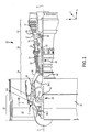
FIG. 1 is a schematic cross-section of a gas turbine engine, in accordance with various embodiments; -
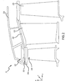
FIG. 2 is an enlarged schematic cross-section of a portion of a high pressure turbine section of the gas turbine engine ofFIG. 1 , in accordance with various embodiments; -
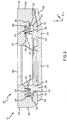
FIG. 3 is an enlarged schematic cross-section of the high pressure turbine section ofFIG. 2 illustrating bellows seals between a blade outer air seal and a shroud block, in accordance with various embodiments; and -
FIG. 4 is a cross-sectional view of the bellows seals ofFIG. 3 , in accordance with various embodiments. - The detailed description of exemplary embodiments herein makes reference to the accompanying drawings, which show exemplary embodiments by way of illustration and their best mode. While these exemplary embodiments are described in sufficient detail to enable those skilled in the art to practice the inventions, it should be understood that other embodiments may be realized and that logical, chemical and mechanical changes may be made without departing from the scope of the inventions. Thus, the detailed description herein is presented for purposes of illustration only and not of limitation. For example, the steps recited in any of the method or process descriptions may be executed in any order and are not necessarily limited to the order presented. Furthermore, any reference to singular includes plural embodiments, and any reference to more than one component or step may include a singular embodiment or step. Also, any reference to attached, fixed, connected or the like may include permanent, removable, temporary, partial, full and/or any other possible attachment option. Additionally, any reference to without contact (or similar phrases) may also include reduced contact or minimal contact.
- In various embodiments and with reference to
FIG. 1 , agas turbine engine 20 is provided. An A-R-C axis is shown throughout the drawings to illustrate the axial, radial, and circumferential directions, respectively. Thegas turbine engine 20 may be a two-spool turbofan that generally incorporates afan section 22, acompressor section 24, acombustor section 26 and aturbine section 28. Alternative engines may include, for example, an augmentor section among other systems or features. In operation, thefan section 22 can drive coolant (e.g., air) along a bypass flow path B while thecompressor section 24 can drive coolant along a core flow path C for compression and communication into thecombustor section 26 then expansion through theturbine section 28. Although depicted as a two-spool turbofangas turbine engine 20 herein, it should be understood that the concepts described herein are not limited to use with two-spool turbofans as the teachings may be applied to other types of turbine engines including turbojet, turboprop, turboshaft, or power generation turbines, with or without geared fan, geared compressor or three-spool architectures. - The
gas turbine engine 20 may generally comprise alow speed spool 30 and ahigh speed spool 32 mounted for rotation about an engine central longitudinal axis A-A' relative to an enginestatic structure 36 or engine case viaseveral bearing systems 38, 38-1, and 38-2. It should be understood that various bearingsystems 38 at various locations may alternatively or additionally be provided, including for example, the bearingsystem 38, the bearing system 38-1, and the bearing system 38-2. - The
low speed spool 30 may generally comprise aninner shaft 40 that interconnects afan 42, alow pressure compressor 44 and alow pressure turbine 46. Theinner shaft 40 may be connected to thefan 42 through a gearedarchitecture 48 that can drive thefan 42 at a lower speed than thelow speed spool 30. The gearedarchitecture 48 may comprise agear assembly 60 enclosed within agear housing 62. Thegear assembly 60 couples theinner shaft 40 to a rotating fan structure. Thehigh speed spool 32 may comprise anouter shaft 50 that interconnects ahigh pressure compressor 52 andhigh pressure turbine 54. Acombustor 26 may be located betweenhigh pressure compressor 52 andhigh pressure turbine 54. Amid-turbine frame 57 of the enginestatic structure 36 may be located generally between thehigh pressure turbine 54 and thelow pressure turbine 46.Mid-turbine frame 57 may support one ormore bearing systems 38 in theturbine section 28. Theinner shaft 40 and theouter shaft 50 may be concentric and rotate via bearingsystems 38 about the engine central longitudinal axis A-A', which is collinear with their longitudinal axes. As used herein, a "high pressure" compressor or turbine experiences a higher pressure than a corresponding "low pressure" compressor or turbine. - The airflow of core flow path C may be received and conditioned by a fan exit stator 70. After conditioning, the airflow of core flow path C may be compressed by the
low pressure compressor 44 then thehigh pressure compressor 52, mixed and burned with fuel in thecombustor 26, then expanded over thehigh pressure turbine 54 and thelow pressure turbine 46. Theturbines low speed spool 30 andhigh speed spool 32 in response to the expansion. - The
gas turbine engine 20 may be, for example, a high-bypass ratio geared engine. In various embodiments, the bypass ratio of thegas turbine engine 20 may be greater than about six (6). In various embodiments, the bypass ratio of thegas turbine engine 20 may be greater than ten (10). In various embodiments, the gearedarchitecture 48 may be an epicyclic gear train, such as a star gear system (sun gear in meshing engagement with a plurality of star gears supported by a carrier and in meshing engagement with a ring gear) or other gear system. The gearedarchitecture 48 may have a gear reduction ratio of greater than about 2.3 and thelow pressure turbine 46 may have a pressure ratio that is greater than about five (5). In various embodiments, the bypass ratio of thegas turbine engine 20 is greater than about ten (10:1). In various embodiments, the diameter of thefan 42 may be significantly larger than that of thelow pressure compressor 44, and thelow pressure turbine 46 may have a pressure ratio that is greater than about five (5:1). Thelow pressure turbine 46 pressure ratio may be measured prior to the inlet of thelow pressure turbine 46 as related to the pressure at the outlet of thelow pressure turbine 46 prior to an exhaust nozzle. It should be understood, however, that the above parameters are exemplary of various embodiments of a suitable geared architecture engine and that the present disclosure contemplates other gas turbine engines including direct drive turbofans. A gas turbine engine may comprise an industrial gas turbine (IGT) or a geared engine, such as a geared turbofan, or non-geared engine, such as a turbofan, a turboshaft, or may comprise any gas turbine engine as desired. - In various embodiments, the
low pressure compressor 44, thehigh pressure compressor 52, thelow pressure turbine 46, and thehigh pressure turbine 54 may comprise one or more stages or sets of rotating blades and one or more stages or sets of stationary vanes axially interspersed with the associated blade stages but non-rotating about engine central longitudinal axis A-A'. The compressor andturbine sections gas turbine engine 20 are multiple rotor disks, which may include one or more cover plates or minidisks. Minidisks may be configured to receive balancing weights or inserts for balancing the rotor systems. - With reference now to
FIGS. 1 and2 , a portion of the highpressure turbine section 54 includes afirst rotor blade 200, avane 202, and asecond rotor blade 204. Thefirst rotor blade 200 and thesecond rotor blade 204 are each configured to rotate about the axis A-A' relative tovane 202 in response to receiving a flow of fluid from thecombustor section 26. Thus, power from the flow is converted to mechanical power, or torque, by thefirst rotor blade 200 and thesecond rotor blade 204. Thevane 202 is coupled to aframe 214 of thehigh pressure turbine 54 and conditions the flow of air between thefirst rotor blade 200 and thesecond rotor blade 204. Thevane 202 thus acts as a stator and does not rotate relative to the axis A-A'. - A blade outer air seal (BOAS) 208 is located radially outward from the
first rotor blade 200. TheBOAS 208 is designed to function as a seal to reduce axial air leakage between thefirst rotor blade 200 and theframe 214. Ashroud block 210 may be positioned radially outward from theBOAS 208 and may be coupled to theframe 214. Theshroud block 210 may resist movement of theBOAS 208 relative to theframe 214. Stated differently, theshroud block 210 may retain theBOAS 208 in place relative to theframe 214. TheBOAS 208, theshroud block 210, and thefirst rotor blade 200 may be referred to as aBOAS assembly 207. - It is desirable to reduce radial leakage of air between the
BOAS 208 and theshroud block 210. In that regard and with reference toFIG. 3 , theBOAS assembly 207 may include bellows seals, or "W seals," between theBOAS 208 and theshroud block 210 to reduce such radial air leakage. Although the disclosure is directed to providing a seal between a BOAS and a shroud block in the highpressure turbine section 54, one skilled in the art will realize that the features disclosed herein may be equally applicable to the lowpressure turbine section 46, the highpressure compressor section 52, and the lowpressure compressor section 44. - The
shroud block 210 may include a shroudmain body 300 having aforward end 302 and anaft end 304 that is located aft relative to theforward end 302. Theshroud block 210 may further include a shroud forwardradial portion 306 that extends radially inward from the shroudmain body 300. Theshroud block 210 may further include a shroud aftradial portion 308 that likewise extends radially inward from the shroudmain body 300. - The
shroud block 210 may further include a shroud forwardaxial portion 310 extending axially aft from the shroud forwardradial portion 306. In various embodiments, the shroud forwardaxial portion 310 may be located at a radially inward end of the shroud forwardradial portion 306. Theshroud block 210 may further include a shroud aftaxial portion 312 extending axially forward from the shroud aftradial portion 308. In various embodiments, the shroud aftaxial portion 312 may be located at a radially inward end of the shroud aftradial portion 308. - The
BOAS 208 may include a BOASmain body 314. TheBOAS 208 may further include a BOAS forwardradial portion 316 extending radially outward from the BOASmain body 314. TheBOAS 208 may further include a BOAS aftradial portion 318 that likewise extends radially outward from the BOASmain body 314. - The BOAS forward
radial portion 316 may include a forwardinner portion 338 that is connected to the BOASmain body 314 and extends radially outward from the BOASmain body 314. The BOAS forwardradial portion 316 may further include a forwardouter portion 340 that is connected to the forwardinner portion 338 and extends radially outward from the forwardinner portion 338. - The BOAS aft
radial portion 318 may include an aftinner portion 342 that is connected to the BOASmain body 314 and extends radially outward from the BOASmain body 314. The BOAS aftradial portion 318 may further include an aftouter portion 343 that is connected to the aftinner portion 342 and extends radially outward from the aftinner portion 342. - The BOAS
main body 314 may include aforward wing 348 that extends axially forward from the BOAS forwardradial portion 316. The BOASmain body 314 may further include anaft wing 350 that extend axially aft from the BOAS aftradial portion 318. - The
BOAS 208 may further include a BOAS forwardaxial portion 320 that extends axially forward from the BOAS forwardradial portion 316. The BOAS forwardaxial portion 320 may be connected to the BOAS forwardradial portion 316 between the forwardinner portion 338 and the forwardouter portion 340. TheBOAS 208 may further include a BOAS aftaxial portion 322 that extends axially aft from the BOAS aftradial portion 318. The BOAS aftaxial portion 322 may be connected to the BOAS aftradial portion 318 between the aftinner portion 342 and the aftouter portion 343. - In various embodiments, the shroud block
main body 300 may extend at least from the BOAS forwardradial portion 316 to the BOAS aftradial portion 318. Likewise, in various embodiments, the BOASmain body 314 may extend at least from the shroud forwardradial portion 306 to the shroud aftradial portion 308. - One or more bellows seal may be positioned between the
shroud block 210 and the BOASmain body 314. In particular, a first bellowsseal 324 may be located between the shroud forwardradial portion 306 and the BOAS forwardradial portion 316. The shroud forwardradial portion 306 may define an aft-facingshroud face 328, and the forwardouter portion 340 of the BOAS forwardradial portion 316 may define a forward-facing BOAS face 332. The first bellowsseal 324 may extend from the aft-facingshroud face 328 to the forward-facing BOAS face 332. In that regard, the first bellows seal 324 may resist radial leakage of air between theBOAS 208 and theshroud block 210. - Likewise, a second bellows
seal 326 may be located between the BOAS aftradial portion 318 and the shroud aftradial portion 308. In particular, the shroud aftradial portion 308 may define a forward-facingshroud face 330, and the aftouter portion 343 of the BOAS aftradial portion 318 may define an aft-facing BOAS face 334. The second bellowsseal 326 may extend from the forward-facingshroud face 330 to the aft-facing BOAS face 334. In that regard, the second bellows seal 326 may resist radial leakage of air between theBOAS 208 and theshroud block 210. - An
axial tolerance 336 may exist between the BOAS forwardaxial portion 320 and the shroud forwardradial portion 306. Theaxial tolerance 336 may also or instead be located between the BOAS aftaxial portion 322 and the shroud aftradial portion 308. Theaxial tolerance 336 may allow axial movement of theBOAS 208 relative to theshroud block 210 in the forward or aft direction. For example, theaxial tolerance 336 may be between 20 thousandths of an inch (20 mils, 0.51 millimeters (mm)) and 100 mils (2.5 mm), between 40 mils (1.0 mm) and 80 mils (2.0 mm), or about 60 mils (1.5 mm). Where used in this context, about refers to the stated value plus or minus 10 percent (10%) of the stated value. - Referring to
FIGS. 3 and4 , aradial gap 344 may exist between the shroudmain body 300 and the BOAS aftaxial portion 322 where the second bellows seal 326 is located. The second bellowsseal 326 may have aradial distance 402 in the radial direction. In various embodiments, theradial distance 402 of the second bellows seal 326 may be about the same as theradial gap 344. The relationship between theradial gap 344 and theradial distance 402 of the second bellows seal 326 may likewise apply to the first bellows seal 324 and its corresponding location. - An
axial gap 346 may exist between the aftouter portion 343 and the shroud aftradial portion 308 where the second bellows seal 326 is located. The second bellowsseal 326 may have anaxial distance 400 in the axial direction in response to being in a fully extended position. Stated differently, the second bellows seal 326 has theaxial distance 400 in response to a lack of pressure being applied to the second bellowsseal 326. In various embodiments, theaxial distance 400 of the second bellows seal 326 in the fully extended position may be greater than theaxial gap 346. For example, theaxial distance 400 may be 5%, 10%, 20%, 40%, or the like greater than theaxial gap 346. - In that regard, in response to being positioned between the aft
outer portion 343 and the shroud aftradial portion 308, the second bellows seal 326 may be compressed between the aft-facing BOAS face 334 of the aftouter portion 343 and the forward-facingshroud face 330 of the shroud aftradial portion 308. Such compression of the second bellows seal 326 may increase the ability of the second bellows seal 326 to resist air leakage. The relationship between theaxial gap 346 and theaxial distance 400 of the second bellows seal 326 may likewise apply to the first bellows seal 324 and its corresponding location. - As shown, the bellows seals 324, 326 may include 5 bends. However, in various embodiments, bellows seals in accordance with various embodiments may include any quantity of bends.
- The first bellows
seal 324 and the second bellows seal 326 may include any of a variety of materials. With reference toFIGS. 1 and3 , the material of the bellows seals 324, 326 may be selected based on the location of the bellows seals 324, 326 within thegas turbine engine 20. In particular, it may be desirable for the material of the bellows seals 324, 326 to have a greater temperature resistance (i.e., resist deformation at a relatively greater temperature) if located in the highpressure turbine section 54 or the highpressure compressor section 52 rather than the lowpressure turbine section 46 or the lowpressure compressor section 44. - In various embodiments, the bellows seals 324, 326 may include a nickel-based alloy, a cobalt-based alloy, or the like. Where used in this context, a nickel-based alloy includes more nickel by weight percent (wt%) than any other single element and, where used in this context, a cobalt-based alloy includes more cobalt by wt% than any other single element. For example, a compound having 40% nickel, 30% cobalt and 30% aluminum may be referred to as a nickel-based alloy.
- For example, the bellows seals 324, 326 may include a high performance nickel-based super alloy. As another example, the bellows seals 324, 326 may include a cobalt-nickel-chromium-tungsten alloy. As yet another example, the bellows seals 324, 326 may include an austenitic nickel-chromium-based alloy.
- Benefits, other advantages, and solutions to problems have been described herein with regard to specific embodiments. Furthermore, the connecting lines shown in the various figures contained herein are intended to represent exemplary functional relationships and/or physical couplings between the various elements. It should be noted that many alternative or additional functional relationships or physical connections may be present in a practical system. However, the benefits, advantages, solutions to problems, and any elements that may cause any benefit, advantage, or solution to occur or become more pronounced are not to be construed as critical, required, or essential features or elements of the inventions. The scope of the invention is accordingly to be limited by nothing other than the appended claims, in which reference to an element in the singular is not intended to mean "one and only one" unless explicitly so stated, but rather "one or more." Moreover, where a phrase similar to "at least one of A, B, or C" is used in the claims, it is intended that the phrase be interpreted to mean that A alone may be present in an embodiment, B alone may be present in an embodiment, C alone may be present in an embodiment, or that any combination of the elements A, B and C may be present in a single embodiment; for example, A and B, A and C, B and C, or A and B and C. Different cross-hatching is used throughout the figures to denote different parts but not necessarily to denote the same or different materials.
- Systems, methods and apparatus are provided herein. In the detailed description herein, references to "one embodiment", "an embodiment", "various embodiments", etc., indicate that the embodiment described may include a particular feature, structure, or characteristic, but every embodiment may not necessarily include the particular feature, structure, or characteristic. Moreover, such phrases are not necessarily referring to the same embodiment. Further, when a particular feature, structure, or characteristic is described in connection with an embodiment, it is submitted that it is within the knowledge of one skilled in the art to affect such feature, structure, or characteristic in connection with other embodiments whether or not explicitly described. After reading the description, it will be apparent to one skilled in the relevant art(s) how to implement the disclosure in alternative embodiments.
- Furthermore, no element, component, or method step in the present disclosure is intended to be dedicated to the public regardless of whether the element, component, or method step is explicitly recited in the claims. No claim element herein is to be construed under the provisions of 35 U.S.C. 112(f), unless the element is expressly recited using the phrase "means for." As used herein, the terms "comprises", "comprising", or any other variation thereof, are intended to cover a non-exclusive inclusion, such that a process, method, article, or apparatus that comprises a list of elements does not include only those elements but may include other elements not expressly listed or inherent to such process, method, article, or apparatus.
Claims (15)
- A blade outer air seal (BOAS) assembly, comprising:a rotor blade configured to rotate about an axis;a BOAS positioned radially outward from the rotor blade and having a forward-facing BOAS face;a shroud block positioned radially outward from the BOAS, having an aft-facing shroud face, and being configured to support the BOAS; anda first bellows seal extending from the forward-facing BOAS face to the aft-facing shroud face and configured to reduce fluid leakage radially between the BOAS and the shroud block.
- The BOAS assembly of claim 1, further comprising a second bellows seal, wherein:the BOAS further includes an aft-facing BOAS face;the shroud block further includes a forward-facing shroud face; andthe second bellows seal extends from the aft-facing BOAS face to the forward-facing shroud face and is configured to further reduce the fluid leakage radially between the BOAS and the shroud block.
- The BOAS assembly of claim 1 or 2, wherein:the shroud block includes a shroud main body, a shroud forward radial portion extending radially inward from the shroud main body, and a shroud forward axial portion extending axially aft from the shroud forward radial portion;the BOAS includes a BOAS main body, a BOAS forward radial portion extending radially outward from the BOAS main body, and a BOAS forward axial portion extending axially forward from the BOAS forward radial portion;the forward-facing BOAS face is defined by the BOAS forward radial portion; andthe aft-facing shroud face is defined by the shroud forward radial portion.
- The BOAS assembly of claim 3, wherein the BOAS forward axial portion is received between the shroud main body and the shroud forward axial portion to resist separation of the BOAS from the shroud block, and/or
wherein, optionally, the BOAS main body includes a forward wing extending axially forward from the BOAS forward radial portion, and/or
wherein, optionally, the BOAS forward radial portion has a forward inner portion connected to the BOAS main body and a forward outer portion connected to the forward inner portion and extending radially outward from the forward inner portion, and the BOAS forward axial portion is positioned radially between the forward outer portion and the forward inner portion, and/or
wherein, optionally, an axial tolerance exists between the BOAS forward axial portion and the shroud forward radial portion to allow axial movement of the BOAS relative to the shroud block. - The BOAS assembly of any preceding claim, wherein an axial gap extends from the forward-facing BOAS face to the aft-facing shroud face, and the first bellows seal has an axial length in a fully extended position that is greater than the axial gap such that the first bellows seal is compressed between the forward-facing BOAS face and the aft-facing shroud face.
- The BOAS assembly of any preceding claim, wherein the first bellows seal includes at least one of a cobalt based alloy or a nickel based alloy.
- A blade outer air seal (BOAS) assembly, comprising:a rotor blade configured to rotate about an axis;a BOAS positioned radially outward from the rotor blade and having an aft-facing BOAS face;a shroud block positioned radially outward from the BOAS, having a forward-facing shroud face, and being configured to support the BOAS; anda bellows seal extending from the aft-facing BOAS face to the forward-facing shroud face and configured to reduce fluid leakage radially between the BOAS and the shroud block.
- The BOAS assembly of claim 7, wherein:the shroud block includes a shroud main body, a shroud aft radial portion extending radially inward from the shroud main body, and a shroud aft axial portion extending axially forward from the shroud aft radial portion;the BOAS includes a BOAS main body, a BOAS aft radial portion extending radially outward from the BOAS main body, and a BOAS aft axial portion extending axially aft from the BOAS aft radial portion;the aft-facing BOAS face is defined by the BOAS aft radial portion; andthe forward-facing shroud face is defined by the shroud aft radial portion.
- The BOAS assembly of claim 8, wherein the BOAS aft axial portion is received between the shroud main body and the shroud aft axial portion to resist separation of the BOAS from the shroud block.
- The BOAS assembly of claim 8 or 9, wherein the BOAS main body includes an aft wing extending axially aft from the BOAS aft radial portion.
- The BOAS assembly of claim 8, 9 or 10, wherein the BOAS aft radial portion has an aft inner portion connected to the BOAS main body and an aft outer portion connected to the aft inner portion and extending radially outward from the aft inner portion, and the BOAS aft axial portion is positioned radially between the aft outer portion and the aft inner portion.
- The BOAS assembly of claim 8, 9, 10 or 11, wherein an axial tolerance exists between the BOAS aft axial portion and the shroud aft radial portion to allow axial movement of the BOAS relative to the shroud block.
- The BOAS assembly of any of claims 7 to 12, wherein an axial gap exists from the aft-facing BOAS face to the forward-facing shroud face, and the bellows seal has an axial length in a fully extended position that is greater than the axial gap such that the bellows seal is compressed between the aft-facing BOAS face and the forward-facing shroud face, and/or
wherein, optionally, the bellows seal includes at least one of a cobalt based alloy or a nickel based alloy. - A gas turbine engine having an axis and comprising:a compressor section configured to compress a fluid;a combustor section configured to mix the fluid with fuel and combust the fluid and the fuel to generate exhaust; anda turbine section configured to receive the exhaust and convert the exhaust into torque,wherein at least one of the compressor section or the turbine section includes:a rotor blade configured to rotate about the axis,a blade outer air seal (BOAS) positioned radially outward from the rotor blade and having a forward-facing BOAS face,a shroud block positioned radially outward from the BOAS, having an aft-facing shroud face, and being configured to support the BOAS, anda first bellows seal extending from the forward-facing BOAS face to the aft-facing shroud face and configured to reduce fluid leakage radially between the BOAS and the shroud block.
- The gas turbine engine of claim 14, wherein:the BOAS further includes an aft-facing BOAS face;the shroud block further includes a forward-facing shroud face; and
the at least one of the compressor section or the turbine section further includes a second bellows seal that extends from the aft-facing BOAS face to the forward-facing shroud face and is configured to further reduce the fluid leakage radially between the BOAS and the shroud block, and/orwherein, optionally:the shroud block includes a shroud main body, a shroud forward radial portion extending radially inward from the shroud main body, and a shroud forward axial portion extending axially aft from the shroud forward radial portion;the BOAS includes a BOAS main body, a BOAS forward radial portion extending radially outward from the BOAS main body, and a BOAS forward axial portion extending axially forward from the BOAS forward radial portion;the forward-facing BOAS face is defined by the BOAS forward radial portion; andthe aft-facing shroud face is defined by the shroud forward radial portion.
Applications Claiming Priority (2)
| Application Number | Priority Date | Filing Date | Title |
|---|---|---|---|
| US201762506157P | 2017-05-15 | 2017-05-15 | |
| US15/623,208 US10533446B2 (en) | 2017-05-15 | 2017-06-14 | Alternative W-seal groove arrangement |
Publications (2)
| Publication Number | Publication Date |
|---|---|
| EP3404214A1 true EP3404214A1 (en) | 2018-11-21 |
| EP3404214B1 EP3404214B1 (en) | 2023-03-22 |
Family
ID=62110908
Family Applications (1)
| Application Number | Title | Priority Date | Filing Date |
|---|---|---|---|
| EP18170407.3A Active EP3404214B1 (en) | 2017-05-15 | 2018-05-02 | Blade outer air seal assembly and gas turbine engine with such an assembly |
Country Status (2)
| Country | Link |
|---|---|
| US (1) | US10533446B2 (en) |
| EP (1) | EP3404214B1 (en) |
Families Citing this family (3)
| Publication number | Priority date | Publication date | Assignee | Title |
|---|---|---|---|---|
| US10392967B2 (en) | 2017-11-13 | 2019-08-27 | General Electric Company | Compliant seal component and associated method |
| CN111188789A (en) * | 2020-01-22 | 2020-05-22 | 西安陕鼓通风设备有限公司 | Centrifugal fan with shaft end sealing device capable of adapting to thermal deformation of casing |
| US11773741B2 (en) | 2021-06-09 | 2023-10-03 | General Electric Company | Compliant shroud designs with variable stiffness |
Citations (5)
| Publication number | Priority date | Publication date | Assignee | Title |
|---|---|---|---|---|
| US5048288A (en) * | 1988-12-20 | 1991-09-17 | United Technologies Corporation | Combined turbine stator cooling and turbine tip clearance control |
| US5423659A (en) * | 1994-04-28 | 1995-06-13 | United Technologies Corporation | Shroud segment having a cut-back retaining hook |
| US6352267B1 (en) * | 1999-03-12 | 2002-03-05 | John E. Rode | Adjustaby sizeable ring seal |
| US20160003080A1 (en) * | 2013-02-20 | 2016-01-07 | United Technologies Corporation | Gas turbine engine seal assembly |
| US20170114670A1 (en) * | 2014-06-12 | 2017-04-27 | General Electric Company | Multi-piece shroud hanger assembly |
Family Cites Families (13)
| Publication number | Priority date | Publication date | Assignee | Title |
|---|---|---|---|---|
| US4573866A (en) * | 1983-05-02 | 1986-03-04 | United Technologies Corporation | Sealed shroud for rotating body |
| US4642024A (en) * | 1984-12-05 | 1987-02-10 | United Technologies Corporation | Coolable stator assembly for a rotary machine |
| US5738490A (en) | 1996-05-20 | 1998-04-14 | Pratt & Whitney Canada, Inc. | Gas turbine engine shroud seals |
| US7207771B2 (en) * | 2004-10-15 | 2007-04-24 | Pratt & Whitney Canada Corp. | Turbine shroud segment seal |
| US7600967B2 (en) * | 2005-07-30 | 2009-10-13 | United Technologies Corporation | Stator assembly, module and method for forming a rotary machine |
| US8079807B2 (en) | 2010-01-29 | 2011-12-20 | General Electric Company | Mounting apparatus for low-ductility turbine shroud |
| US8926270B2 (en) * | 2010-12-17 | 2015-01-06 | General Electric Company | Low-ductility turbine shroud flowpath and mounting arrangement therefor |
| US9175579B2 (en) * | 2011-12-15 | 2015-11-03 | General Electric Company | Low-ductility turbine shroud |
| FR3003301B1 (en) | 2013-03-14 | 2018-01-05 | Safran Helicopter Engines | TURBINE RING FOR TURBOMACHINE |
| WO2015112662A1 (en) * | 2014-01-23 | 2015-07-30 | United Technologies Corporation | Conformal air seal with low friction maxmet layer |
| CA2924866A1 (en) * | 2015-04-29 | 2016-10-29 | Daniel K. Vetters | Composite keystoned blade track |
| US10184352B2 (en) * | 2015-06-29 | 2019-01-22 | Rolls-Royce North American Technologies Inc. | Turbine shroud segment with integrated cooling air distribution system |
| US10385716B2 (en) | 2015-07-02 | 2019-08-20 | Unted Technologies Corporation | Seal for a gas turbine engine |
-
2017
- 2017-06-14 US US15/623,208 patent/US10533446B2/en active Active
-
2018
- 2018-05-02 EP EP18170407.3A patent/EP3404214B1/en active Active
Patent Citations (5)
| Publication number | Priority date | Publication date | Assignee | Title |
|---|---|---|---|---|
| US5048288A (en) * | 1988-12-20 | 1991-09-17 | United Technologies Corporation | Combined turbine stator cooling and turbine tip clearance control |
| US5423659A (en) * | 1994-04-28 | 1995-06-13 | United Technologies Corporation | Shroud segment having a cut-back retaining hook |
| US6352267B1 (en) * | 1999-03-12 | 2002-03-05 | John E. Rode | Adjustaby sizeable ring seal |
| US20160003080A1 (en) * | 2013-02-20 | 2016-01-07 | United Technologies Corporation | Gas turbine engine seal assembly |
| US20170114670A1 (en) * | 2014-06-12 | 2017-04-27 | General Electric Company | Multi-piece shroud hanger assembly |
Also Published As
| Publication number | Publication date |
|---|---|
| US20180328214A1 (en) | 2018-11-15 |
| EP3404214B1 (en) | 2023-03-22 |
| US10533446B2 (en) | 2020-01-14 |
Similar Documents
| Publication | Publication Date | Title |
|---|---|---|
| EP3351740B1 (en) | Section of a gas turbine comprising a segmented blade outer air seal | |
| EP3112599B1 (en) | Transfer tube and turbine section comprising transfer tube | |
| EP2900956A1 (en) | Seal assembly for a static structure of a gas turbine engine | |
| EP3447249B1 (en) | Sealing configurations with active cooling features | |
| US10018066B2 (en) | Mini blind stator leakage reduction | |
| EP3404214B1 (en) | Blade outer air seal assembly and gas turbine engine with such an assembly | |
| EP3051072A1 (en) | Airfoil module | |
| EP3112615A1 (en) | Cantilevered stator vane and stator assembly for a rotary machine | |
| EP3244014B1 (en) | Retaining ring assembly for a gas turbine engine | |
| EP3081748B1 (en) | Gas turbine engine system comprising a seal ring | |
| EP3296515A2 (en) | Anti-rotation stator vane assembly | |
| EP3546700A1 (en) | Double bore basket | |
| EP3553278B1 (en) | Axial stiffening ribs/augmentation fins | |
| EP3101228B1 (en) | Flow splitting baffle | |
| EP3112602B1 (en) | Break-in system for gapping and leakage control | |
| US11408300B2 (en) | Rotor overspeed protection assembly | |
| EP3309361A1 (en) | Seal, corresponding engine section and gas turbine engine | |
| EP3101232A1 (en) | Rotor disk, corresponding assembly and gas turbine engine | |
| EP3453836B1 (en) | Stator vane support with anti-rotation features |
Legal Events
| Date | Code | Title | Description |
|---|---|---|---|
| PUAI | Public reference made under article 153(3) epc to a published international application that has entered the european phase |
Free format text: ORIGINAL CODE: 0009012 |
|
| STAA | Information on the status of an ep patent application or granted ep patent |
Free format text: STATUS: THE APPLICATION HAS BEEN PUBLISHED |
|
| AK | Designated contracting states |
Kind code of ref document: A1 Designated state(s): AL AT BE BG CH CY CZ DE DK EE ES FI FR GB GR HR HU IE IS IT LI LT LU LV MC MK MT NL NO PL PT RO RS SE SI SK SM TR |
|
| AX | Request for extension of the european patent |
Extension state: BA ME |
|
| STAA | Information on the status of an ep patent application or granted ep patent |
Free format text: STATUS: REQUEST FOR EXAMINATION WAS MADE |
|
| 17P | Request for examination filed |
Effective date: 20190521 |
|
| RBV | Designated contracting states (corrected) |
Designated state(s): AL AT BE BG CH CY CZ DE DK EE ES FI FR GB GR HR HU IE IS IT LI LT LU LV MC MK MT NL NO PL PT RO RS SE SI SK SM TR |
|
| STAA | Information on the status of an ep patent application or granted ep patent |
Free format text: STATUS: EXAMINATION IS IN PROGRESS |
|
| 17Q | First examination report despatched |
Effective date: 20210204 |
|
| RAP1 | Party data changed (applicant data changed or rights of an application transferred) |
Owner name: RAYTHEON TECHNOLOGIES CORPORATION |
|
| STAA | Information on the status of an ep patent application or granted ep patent |
Free format text: STATUS: EXAMINATION IS IN PROGRESS |
|
| GRAP | Despatch of communication of intention to grant a patent |
Free format text: ORIGINAL CODE: EPIDOSNIGR1 |
|
| STAA | Information on the status of an ep patent application or granted ep patent |
Free format text: STATUS: GRANT OF PATENT IS INTENDED |
|
| INTG | Intention to grant announced |
Effective date: 20221005 |
|
| GRAS | Grant fee paid |
Free format text: ORIGINAL CODE: EPIDOSNIGR3 |
|
| GRAA | (expected) grant |
Free format text: ORIGINAL CODE: 0009210 |
|
| STAA | Information on the status of an ep patent application or granted ep patent |
Free format text: STATUS: THE PATENT HAS BEEN GRANTED |
|
| AK | Designated contracting states |
Kind code of ref document: B1 Designated state(s): AL AT BE BG CH CY CZ DE DK EE ES FI FR GB GR HR HU IE IS IT LI LT LU LV MC MK MT NL NO PL PT RO RS SE SI SK SM TR |
|
| REG | Reference to a national code |
Ref country code: GB Ref legal event code: FG4D |
|
| REG | Reference to a national code |
Ref country code: CH Ref legal event code: EP |
|
| REG | Reference to a national code |
Ref country code: IE Ref legal event code: FG4D |
|
| REG | Reference to a national code |
Ref country code: DE Ref legal event code: R096 Ref document number: 602018047409 Country of ref document: DE |
|
| REG | Reference to a national code |
Ref country code: AT Ref legal event code: REF Ref document number: 1555403 Country of ref document: AT Kind code of ref document: T Effective date: 20230415 |
|
| P01 | Opt-out of the competence of the unified patent court (upc) registered |
Effective date: 20230521 |
|
| REG | Reference to a national code |
Ref country code: LT Ref legal event code: MG9D |
|
| REG | Reference to a national code |
Ref country code: NL Ref legal event code: MP Effective date: 20230322 |
|
| PG25 | Lapsed in a contracting state [announced via postgrant information from national office to epo] |
Ref country code: RS Free format text: LAPSE BECAUSE OF FAILURE TO SUBMIT A TRANSLATION OF THE DESCRIPTION OR TO PAY THE FEE WITHIN THE PRESCRIBED TIME-LIMIT Effective date: 20230322 Ref country code: NO Free format text: LAPSE BECAUSE OF FAILURE TO SUBMIT A TRANSLATION OF THE DESCRIPTION OR TO PAY THE FEE WITHIN THE PRESCRIBED TIME-LIMIT Effective date: 20230622 Ref country code: LV Free format text: LAPSE BECAUSE OF FAILURE TO SUBMIT A TRANSLATION OF THE DESCRIPTION OR TO PAY THE FEE WITHIN THE PRESCRIBED TIME-LIMIT Effective date: 20230322 Ref country code: LT Free format text: LAPSE BECAUSE OF FAILURE TO SUBMIT A TRANSLATION OF THE DESCRIPTION OR TO PAY THE FEE WITHIN THE PRESCRIBED TIME-LIMIT Effective date: 20230322 Ref country code: HR Free format text: LAPSE BECAUSE OF FAILURE TO SUBMIT A TRANSLATION OF THE DESCRIPTION OR TO PAY THE FEE WITHIN THE PRESCRIBED TIME-LIMIT Effective date: 20230322 |
|
| PGFP | Annual fee paid to national office [announced via postgrant information from national office to epo] |
Ref country code: FR Payment date: 20230420 Year of fee payment: 6 Ref country code: DE Payment date: 20230419 Year of fee payment: 6 |
|
| REG | Reference to a national code |
Ref country code: AT Ref legal event code: MK05 Ref document number: 1555403 Country of ref document: AT Kind code of ref document: T Effective date: 20230322 |
|
| PG25 | Lapsed in a contracting state [announced via postgrant information from national office to epo] |
Ref country code: SE Free format text: LAPSE BECAUSE OF FAILURE TO SUBMIT A TRANSLATION OF THE DESCRIPTION OR TO PAY THE FEE WITHIN THE PRESCRIBED TIME-LIMIT Effective date: 20230322 Ref country code: NL Free format text: LAPSE BECAUSE OF FAILURE TO SUBMIT A TRANSLATION OF THE DESCRIPTION OR TO PAY THE FEE WITHIN THE PRESCRIBED TIME-LIMIT Effective date: 20230322 Ref country code: GR Free format text: LAPSE BECAUSE OF FAILURE TO SUBMIT A TRANSLATION OF THE DESCRIPTION OR TO PAY THE FEE WITHIN THE PRESCRIBED TIME-LIMIT Effective date: 20230623 Ref country code: FI Free format text: LAPSE BECAUSE OF FAILURE TO SUBMIT A TRANSLATION OF THE DESCRIPTION OR TO PAY THE FEE WITHIN THE PRESCRIBED TIME-LIMIT Effective date: 20230322 |
|
| PG25 | Lapsed in a contracting state [announced via postgrant information from national office to epo] |
Ref country code: SM Free format text: LAPSE BECAUSE OF FAILURE TO SUBMIT A TRANSLATION OF THE DESCRIPTION OR TO PAY THE FEE WITHIN THE PRESCRIBED TIME-LIMIT Effective date: 20230322 Ref country code: RO Free format text: LAPSE BECAUSE OF FAILURE TO SUBMIT A TRANSLATION OF THE DESCRIPTION OR TO PAY THE FEE WITHIN THE PRESCRIBED TIME-LIMIT Effective date: 20230322 Ref country code: PT Free format text: LAPSE BECAUSE OF FAILURE TO SUBMIT A TRANSLATION OF THE DESCRIPTION OR TO PAY THE FEE WITHIN THE PRESCRIBED TIME-LIMIT Effective date: 20230724 Ref country code: ES Free format text: LAPSE BECAUSE OF FAILURE TO SUBMIT A TRANSLATION OF THE DESCRIPTION OR TO PAY THE FEE WITHIN THE PRESCRIBED TIME-LIMIT Effective date: 20230322 Ref country code: EE Free format text: LAPSE BECAUSE OF FAILURE TO SUBMIT A TRANSLATION OF THE DESCRIPTION OR TO PAY THE FEE WITHIN THE PRESCRIBED TIME-LIMIT Effective date: 20230322 Ref country code: AT Free format text: LAPSE BECAUSE OF FAILURE TO SUBMIT A TRANSLATION OF THE DESCRIPTION OR TO PAY THE FEE WITHIN THE PRESCRIBED TIME-LIMIT Effective date: 20230322 |
|
| PGFP | Annual fee paid to national office [announced via postgrant information from national office to epo] |
Ref country code: GB Payment date: 20230420 Year of fee payment: 6 |
|
| RAP4 | Party data changed (patent owner data changed or rights of a patent transferred) |
Owner name: RTX CORPORATION |
|
| PG25 | Lapsed in a contracting state [announced via postgrant information from national office to epo] |
Ref country code: SK Free format text: LAPSE BECAUSE OF FAILURE TO SUBMIT A TRANSLATION OF THE DESCRIPTION OR TO PAY THE FEE WITHIN THE PRESCRIBED TIME-LIMIT Effective date: 20230322 Ref country code: PL Free format text: LAPSE BECAUSE OF FAILURE TO SUBMIT A TRANSLATION OF THE DESCRIPTION OR TO PAY THE FEE WITHIN THE PRESCRIBED TIME-LIMIT Effective date: 20230322 Ref country code: IS Free format text: LAPSE BECAUSE OF FAILURE TO SUBMIT A TRANSLATION OF THE DESCRIPTION OR TO PAY THE FEE WITHIN THE PRESCRIBED TIME-LIMIT Effective date: 20230722 |
|
| REG | Reference to a national code |
Ref country code: CH Ref legal event code: PL |
|
| REG | Reference to a national code |
Ref country code: DE Ref legal event code: R097 Ref document number: 602018047409 Country of ref document: DE |
|
| PG25 | Lapsed in a contracting state [announced via postgrant information from national office to epo] |
Ref country code: MC Free format text: LAPSE BECAUSE OF FAILURE TO SUBMIT A TRANSLATION OF THE DESCRIPTION OR TO PAY THE FEE WITHIN THE PRESCRIBED TIME-LIMIT Effective date: 20230322 |
|
| PLBE | No opposition filed within time limit |
Free format text: ORIGINAL CODE: 0009261 |
|
| STAA | Information on the status of an ep patent application or granted ep patent |
Free format text: STATUS: NO OPPOSITION FILED WITHIN TIME LIMIT |
|
| REG | Reference to a national code |
Ref country code: BE Ref legal event code: MM Effective date: 20230531 |
|
| PG25 | Lapsed in a contracting state [announced via postgrant information from national office to epo] |
Ref country code: SI Free format text: LAPSE BECAUSE OF FAILURE TO SUBMIT A TRANSLATION OF THE DESCRIPTION OR TO PAY THE FEE WITHIN THE PRESCRIBED TIME-LIMIT Effective date: 20230322 Ref country code: MC Free format text: LAPSE BECAUSE OF FAILURE TO SUBMIT A TRANSLATION OF THE DESCRIPTION OR TO PAY THE FEE WITHIN THE PRESCRIBED TIME-LIMIT Effective date: 20230322 Ref country code: LU Free format text: LAPSE BECAUSE OF NON-PAYMENT OF DUE FEES Effective date: 20230502 Ref country code: LI Free format text: LAPSE BECAUSE OF NON-PAYMENT OF DUE FEES Effective date: 20230531 Ref country code: DK Free format text: LAPSE BECAUSE OF FAILURE TO SUBMIT A TRANSLATION OF THE DESCRIPTION OR TO PAY THE FEE WITHIN THE PRESCRIBED TIME-LIMIT Effective date: 20230322 Ref country code: CZ Free format text: LAPSE BECAUSE OF FAILURE TO SUBMIT A TRANSLATION OF THE DESCRIPTION OR TO PAY THE FEE WITHIN THE PRESCRIBED TIME-LIMIT Effective date: 20230322 Ref country code: CH Free format text: LAPSE BECAUSE OF NON-PAYMENT OF DUE FEES Effective date: 20230531 |
|
| 26N | No opposition filed |
Effective date: 20240102 |
|
| REG | Reference to a national code |
Ref country code: IE Ref legal event code: MM4A |