EP3434209A1 - Shockwave generating device - Google Patents
Shockwave generating device Download PDFInfo
- Publication number
- EP3434209A1 EP3434209A1 EP18185152.8A EP18185152A EP3434209A1 EP 3434209 A1 EP3434209 A1 EP 3434209A1 EP 18185152 A EP18185152 A EP 18185152A EP 3434209 A1 EP3434209 A1 EP 3434209A1
- Authority
- EP
- European Patent Office
- Prior art keywords
- aperture
- layer
- conductive layer
- insulating layer
- balloon
- Prior art date
- Legal status (The legal status is an assumption and is not a legal conclusion. Google has not performed a legal analysis and makes no representation as to the accuracy of the status listed.)
- Granted
Links
Images



Classifications
-
- A—HUMAN NECESSITIES
- A61—MEDICAL OR VETERINARY SCIENCE; HYGIENE
- A61B—DIAGNOSIS; SURGERY; IDENTIFICATION
- A61B17/00—Surgical instruments, devices or methods
- A61B17/22—Implements for squeezing-off ulcers or the like on inner organs of the body; Implements for scraping-out cavities of body organs, e.g. bones; for invasive removal or destruction of calculus using mechanical vibrations; for removing obstructions in blood vessels, not otherwise provided for
- A61B17/22004—Implements for squeezing-off ulcers or the like on inner organs of the body; Implements for scraping-out cavities of body organs, e.g. bones; for invasive removal or destruction of calculus using mechanical vibrations; for removing obstructions in blood vessels, not otherwise provided for using mechanical vibrations, e.g. ultrasonic shock waves
- A61B17/22012—Implements for squeezing-off ulcers or the like on inner organs of the body; Implements for scraping-out cavities of body organs, e.g. bones; for invasive removal or destruction of calculus using mechanical vibrations; for removing obstructions in blood vessels, not otherwise provided for using mechanical vibrations, e.g. ultrasonic shock waves in direct contact with, or very close to, the obstruction or concrement
- A61B17/2202—Implements for squeezing-off ulcers or the like on inner organs of the body; Implements for scraping-out cavities of body organs, e.g. bones; for invasive removal or destruction of calculus using mechanical vibrations; for removing obstructions in blood vessels, not otherwise provided for using mechanical vibrations, e.g. ultrasonic shock waves in direct contact with, or very close to, the obstruction or concrement the ultrasound transducer being inside patient's body at the distal end of the catheter
-
- A—HUMAN NECESSITIES
- A61—MEDICAL OR VETERINARY SCIENCE; HYGIENE
- A61B—DIAGNOSIS; SURGERY; IDENTIFICATION
- A61B17/00—Surgical instruments, devices or methods
- A61B17/22—Implements for squeezing-off ulcers or the like on inner organs of the body; Implements for scraping-out cavities of body organs, e.g. bones; for invasive removal or destruction of calculus using mechanical vibrations; for removing obstructions in blood vessels, not otherwise provided for
- A61B17/22004—Implements for squeezing-off ulcers or the like on inner organs of the body; Implements for scraping-out cavities of body organs, e.g. bones; for invasive removal or destruction of calculus using mechanical vibrations; for removing obstructions in blood vessels, not otherwise provided for using mechanical vibrations, e.g. ultrasonic shock waves
- A61B17/22012—Implements for squeezing-off ulcers or the like on inner organs of the body; Implements for scraping-out cavities of body organs, e.g. bones; for invasive removal or destruction of calculus using mechanical vibrations; for removing obstructions in blood vessels, not otherwise provided for using mechanical vibrations, e.g. ultrasonic shock waves in direct contact with, or very close to, the obstruction or concrement
- A61B17/22022—Implements for squeezing-off ulcers or the like on inner organs of the body; Implements for scraping-out cavities of body organs, e.g. bones; for invasive removal or destruction of calculus using mechanical vibrations; for removing obstructions in blood vessels, not otherwise provided for using mechanical vibrations, e.g. ultrasonic shock waves in direct contact with, or very close to, the obstruction or concrement using electric discharge
-
- A—HUMAN NECESSITIES
- A61—MEDICAL OR VETERINARY SCIENCE; HYGIENE
- A61B—DIAGNOSIS; SURGERY; IDENTIFICATION
- A61B17/00—Surgical instruments, devices or methods
- A61B17/22—Implements for squeezing-off ulcers or the like on inner organs of the body; Implements for scraping-out cavities of body organs, e.g. bones; for invasive removal or destruction of calculus using mechanical vibrations; for removing obstructions in blood vessels, not otherwise provided for
- A61B2017/22001—Angioplasty, e.g. PCTA
-
- A—HUMAN NECESSITIES
- A61—MEDICAL OR VETERINARY SCIENCE; HYGIENE
- A61B—DIAGNOSIS; SURGERY; IDENTIFICATION
- A61B17/00—Surgical instruments, devices or methods
- A61B17/22—Implements for squeezing-off ulcers or the like on inner organs of the body; Implements for scraping-out cavities of body organs, e.g. bones; for invasive removal or destruction of calculus using mechanical vibrations; for removing obstructions in blood vessels, not otherwise provided for
- A61B17/22004—Implements for squeezing-off ulcers or the like on inner organs of the body; Implements for scraping-out cavities of body organs, e.g. bones; for invasive removal or destruction of calculus using mechanical vibrations; for removing obstructions in blood vessels, not otherwise provided for using mechanical vibrations, e.g. ultrasonic shock waves
- A61B17/22012—Implements for squeezing-off ulcers or the like on inner organs of the body; Implements for scraping-out cavities of body organs, e.g. bones; for invasive removal or destruction of calculus using mechanical vibrations; for removing obstructions in blood vessels, not otherwise provided for using mechanical vibrations, e.g. ultrasonic shock waves in direct contact with, or very close to, the obstruction or concrement
- A61B17/2202—Implements for squeezing-off ulcers or the like on inner organs of the body; Implements for scraping-out cavities of body organs, e.g. bones; for invasive removal or destruction of calculus using mechanical vibrations; for removing obstructions in blood vessels, not otherwise provided for using mechanical vibrations, e.g. ultrasonic shock waves in direct contact with, or very close to, the obstruction or concrement the ultrasound transducer being inside patient's body at the distal end of the catheter
- A61B2017/22021—Implements for squeezing-off ulcers or the like on inner organs of the body; Implements for scraping-out cavities of body organs, e.g. bones; for invasive removal or destruction of calculus using mechanical vibrations; for removing obstructions in blood vessels, not otherwise provided for using mechanical vibrations, e.g. ultrasonic shock waves in direct contact with, or very close to, the obstruction or concrement the ultrasound transducer being inside patient's body at the distal end of the catheter electric leads passing through the catheter
-
- A—HUMAN NECESSITIES
- A61—MEDICAL OR VETERINARY SCIENCE; HYGIENE
- A61B—DIAGNOSIS; SURGERY; IDENTIFICATION
- A61B17/00—Surgical instruments, devices or methods
- A61B17/22—Implements for squeezing-off ulcers or the like on inner organs of the body; Implements for scraping-out cavities of body organs, e.g. bones; for invasive removal or destruction of calculus using mechanical vibrations; for removing obstructions in blood vessels, not otherwise provided for
- A61B17/22004—Implements for squeezing-off ulcers or the like on inner organs of the body; Implements for scraping-out cavities of body organs, e.g. bones; for invasive removal or destruction of calculus using mechanical vibrations; for removing obstructions in blood vessels, not otherwise provided for using mechanical vibrations, e.g. ultrasonic shock waves
- A61B17/22012—Implements for squeezing-off ulcers or the like on inner organs of the body; Implements for scraping-out cavities of body organs, e.g. bones; for invasive removal or destruction of calculus using mechanical vibrations; for removing obstructions in blood vessels, not otherwise provided for using mechanical vibrations, e.g. ultrasonic shock waves in direct contact with, or very close to, the obstruction or concrement
- A61B2017/22025—Implements for squeezing-off ulcers or the like on inner organs of the body; Implements for scraping-out cavities of body organs, e.g. bones; for invasive removal or destruction of calculus using mechanical vibrations; for removing obstructions in blood vessels, not otherwise provided for using mechanical vibrations, e.g. ultrasonic shock waves in direct contact with, or very close to, the obstruction or concrement applying a shock wave
-
- A—HUMAN NECESSITIES
- A61—MEDICAL OR VETERINARY SCIENCE; HYGIENE
- A61B—DIAGNOSIS; SURGERY; IDENTIFICATION
- A61B17/00—Surgical instruments, devices or methods
- A61B17/22—Implements for squeezing-off ulcers or the like on inner organs of the body; Implements for scraping-out cavities of body organs, e.g. bones; for invasive removal or destruction of calculus using mechanical vibrations; for removing obstructions in blood vessels, not otherwise provided for
- A61B2017/22051—Implements for squeezing-off ulcers or the like on inner organs of the body; Implements for scraping-out cavities of body organs, e.g. bones; for invasive removal or destruction of calculus using mechanical vibrations; for removing obstructions in blood vessels, not otherwise provided for with an inflatable part, e.g. balloon, for positioning, blocking, or immobilisation
-
- A—HUMAN NECESSITIES
- A61—MEDICAL OR VETERINARY SCIENCE; HYGIENE
- A61B—DIAGNOSIS; SURGERY; IDENTIFICATION
- A61B17/00—Surgical instruments, devices or methods
- A61B17/22—Implements for squeezing-off ulcers or the like on inner organs of the body; Implements for scraping-out cavities of body organs, e.g. bones; for invasive removal or destruction of calculus using mechanical vibrations; for removing obstructions in blood vessels, not otherwise provided for
- A61B2017/22051—Implements for squeezing-off ulcers or the like on inner organs of the body; Implements for scraping-out cavities of body organs, e.g. bones; for invasive removal or destruction of calculus using mechanical vibrations; for removing obstructions in blood vessels, not otherwise provided for with an inflatable part, e.g. balloon, for positioning, blocking, or immobilisation
- A61B2017/22061—Implements for squeezing-off ulcers or the like on inner organs of the body; Implements for scraping-out cavities of body organs, e.g. bones; for invasive removal or destruction of calculus using mechanical vibrations; for removing obstructions in blood vessels, not otherwise provided for with an inflatable part, e.g. balloon, for positioning, blocking, or immobilisation for spreading elements apart
-
- A—HUMAN NECESSITIES
- A61—MEDICAL OR VETERINARY SCIENCE; HYGIENE
- A61B—DIAGNOSIS; SURGERY; IDENTIFICATION
- A61B17/00—Surgical instruments, devices or methods
- A61B17/22—Implements for squeezing-off ulcers or the like on inner organs of the body; Implements for scraping-out cavities of body organs, e.g. bones; for invasive removal or destruction of calculus using mechanical vibrations; for removing obstructions in blood vessels, not otherwise provided for
- A61B2017/22051—Implements for squeezing-off ulcers or the like on inner organs of the body; Implements for scraping-out cavities of body organs, e.g. bones; for invasive removal or destruction of calculus using mechanical vibrations; for removing obstructions in blood vessels, not otherwise provided for with an inflatable part, e.g. balloon, for positioning, blocking, or immobilisation
- A61B2017/22062—Implements for squeezing-off ulcers or the like on inner organs of the body; Implements for scraping-out cavities of body organs, e.g. bones; for invasive removal or destruction of calculus using mechanical vibrations; for removing obstructions in blood vessels, not otherwise provided for with an inflatable part, e.g. balloon, for positioning, blocking, or immobilisation to be filled with liquid
-
- A—HUMAN NECESSITIES
- A61—MEDICAL OR VETERINARY SCIENCE; HYGIENE
- A61B—DIAGNOSIS; SURGERY; IDENTIFICATION
- A61B17/00—Surgical instruments, devices or methods
- A61B17/22—Implements for squeezing-off ulcers or the like on inner organs of the body; Implements for scraping-out cavities of body organs, e.g. bones; for invasive removal or destruction of calculus using mechanical vibrations; for removing obstructions in blood vessels, not otherwise provided for
- A61B2017/22051—Implements for squeezing-off ulcers or the like on inner organs of the body; Implements for scraping-out cavities of body organs, e.g. bones; for invasive removal or destruction of calculus using mechanical vibrations; for removing obstructions in blood vessels, not otherwise provided for with an inflatable part, e.g. balloon, for positioning, blocking, or immobilisation
- A61B2017/22065—Functions of balloons
- A61B2017/22069—Immobilising; Stabilising
Definitions
- Angioplasty balloons are commonly used to open calcified lesions in the walls of blood vessels.
- the inflation pressure stores a tremendous amount of energy in the balloon until the calcified lesion breaks or cracks. That stored energy is then released and may stress and injure the wall of the blood vessel.
- Electrohydraulic lithotripsy has been used for breaking calcified lesions in the vasculature.
- Shockwaves generated by lithotripsy electrodes may be used to fracture a calcified lesion to help prevent sudden stress and injury to a blood vessel or valve wall when it is dilated using a balloon.
- Methods, devices, system for treating stenotic or calcified vessels or calcified aortic valves are described, for example in U.S. Patent Pub. No. 2009/0312768 , U.S. Patent Pub. No. 2014/0005576 , and U.S. Patent No. 8,888,788 .
- a balloon is placed adjacent a treatment site and is inflated with a liquid.
- a shockwave generator that produces shockwaves that propagate through the liquid and impinge upon the target tissue prior to balloon expansion.
- shockwave generating device designs and for shockwave generating devices that can improve deliverability to treatment sites and be readily manufactured at low cost.
- Described herein are low-profile electrode assemblies which may be used, for example, in conjunction with shockwave angioplasty balloon catheters. Such devices may, for instance, be used to break up calcified lesions in the vasculature.
- the present disclosure pertains to a device according to the claims 1-7.
- the present disclosure also pertains to devices for generating shockwaves comprising:
- a width of the first aperture is the same as a width of the second aperture.
- a width of the first aperture is different from a width of the second aperture, in which case a width of the first aperture may be smaller than a width of the second aperture, or a width of the first aperture may be greater than a width of the second aperture.
- the device may comprise a plurality of the multi-layer apertures.
- at least some of the plurality of the multi-layer apertures are circumferentially offset from each other.
- the plurality of the multi-layer apertures may comprise:
- At least some of the plurality of the multi-layer apertures are longitudinally offset from each other. In certain of these embodiments, at least some of the plurality of the multi-layer apertures are both circumferentially and longitudinally offset from each other.
- the device may further comprise an additional insulating layer disposed over at least a portion of the outer conductive layer.
- the multi-layer aperture may comprise a third aperture formed in the additional insulating layer, which third aperture may or may not be coaxial with the first aperture and the second aperture.
- a proximal end of the balloon may be attached to a distal end of the elongate shaft, and a distal end of the balloon may be attached to a distal end of the inner electrode assembly.
- the inner elongate member may comprise a lumen.
- a guidewire may be disposed within the lumen of the inner elongate member.
- the disclosure also relates to a system according to claim 8.
- systems that comprise:
- methods of making medical devices for generating shockwaves comprising forming an inner electrode assembly comprising an inner elongate member, an inner conductive layer disposed over the inner elongate member, an insulating layer disposed over the inner conductive layer, an outer conductive layer disposed over the insulating layer, and a multilayer aperture that comprises a first aperture extending through the insulating layer and a second aperture extending through the outer conductive layer, wherein the first aperture and the second aperture are coaxial with one another, and wherein the multi-layer aperture exposes:
- the method further comprises incorporating the inner electrode assembly into a balloon catheter that comprises a balloon and an elongate shaft comprising a lumen that is configured to introduce conductive fluid into the balloon, such that the multi-layer aperture of the inner electrode assembly is positioned inside the balloon.
- forming the inner electrode assembly may comprise:
- the first subassembly may be affixed to the second subassembly by shrinking the second subassembly onto a surface of the first subassembly.
- forming the inner electrode assembly comprises forming the multi-layer aperture in an assembly that comprises the inner elongate member, the inner conductive layer disposed over the inner elongate member, the insulating layer disposed over the inner conductive layer, and the outer conductive layer disposed over the insulating layer.
- the forming the multi-layer aperture comprises:
- the first process may be one that selectively removes the material of the outer conductive layer relative to the material of the insulating layer
- the second process may be one that selectively removes the material of the insulating layer relative to a material of the inner conductive layer.
- Embodiments of the device according to the invention may allow for a smaller profile of the inside of the balloon. As a result, the flexibility of the device may be improved, as may the deliverability. Additionally, embodiments of the invention may be easier to assemble and align than existing systems, which can reduce the cost of manufacture.
- shockwave generators comprising shockwave-generating electrodes.
- the shockwave generators are integral to an inner electrode assembly, which may be sealed within a balloon that is inflated with a conductive fluid (e.g., saline, imaging contrast agent, etc.).
- the inner electrode assembly may be attached to a source of high voltage pulses, for example, ranging from 100 to 10,000 volts, more typically 100 to 3,000 volts, for various pulse durations, which, without wishing to be bound by theory, may generate rapidly expanding and collapsing bubbles, which in turn create mechanical shockwaves within the balloon.
- Shockwaves may be mechanically conducted through the fluid and through a wall of the balloon to apply mechanical stress to break apart calcified lesions that may be present on or in the vasculature walls.
- FIG. 1 is a schematic illustration of a shockwave angioplasty device 100 in accordance with the present disclosure.
- the device 100 of FIG. 1 includes an inner electrode assembly 102, an outer tubular member 120, and a balloon 130.
- the inner electrode assembly 102 includes an inner elongate member 110, an inner conductive layer 112 disposed over the inner elongate member 110, an insulating layer 114 disposed over the inner conductive layer 112, an outer conductive layer 116 disposed over the insulating layer 114, and an optional additional insulating layer 118 disposed over the outer conductive layer 116.
- the inner elongate member 110 may be formed from any suitable material, beneficially a low-friction polymeric material such as, for example, polytetrafluoroethylene (PTFE), fluorinated ethylene propylene (FEP), a copolymer of hexafluoropropylene and tetrafluoroethylene, or high-density polyethylene (HDPE), among other possibilities.
- PTFE polytetrafluoroethylene
- FEP fluorinated ethylene propylene
- HDPE high-density polyethylene
- the inner elongate member 110 may range, for example, from 0.46 mm to 1.1 mm in outer diameter, among other possibilities.
- the inner elongate member 110 may include a guide wire lumen 1101 extending along a length of its longitudinal axis.
- the guide wire lumen 1101 may range, for example, from 0.36 mm to 0.97 mm in diameter, among other possibilities.
- the inner conductive layer 112 and the outer conductive layer 116 may be formed from any material that is able to support the voltages that are required for shockwave generation and to withstand the forces generated by the same.
- the inner conductive layer 112 and the outer conductive layer 116 may be made of tungsten, nickel, iron, steel, including stainless steel, copper, gold, and the like.
- the inner conductive layer 112 may range, for example, from 0.00013 mm to 0.0013 mm in thickness, among other possibilities.
- the outer conductive layer 116 may range, for example, from 0.00013 mm to 0.0013 mm in thickness, among other possibilities.
- the insulating layer 114 may be made of any material having a breakdown voltage that is sufficiently great to withstand voltages that are generated during shockwave generation, for example, fluoropolymers (e.g., PTFE, FEP, etc.), polyethylene terephthalate (PET), polyimide (e.g., Kapton), polyamides, polyamide block polyether copolymers, polyester block copolymers, and the like.
- fluoropolymers e.g., PTFE, FEP, etc.
- PET polyethylene terephthalate
- polyimide e.g., Kapton
- polyamides polyamide block polyether copolymers
- polyester block copolymers polyester block copolymers, and the like.
- the insulating layer 114 may be formed from a shrinkable material, for example, a heat-shrinkable material.
- the insulating layer 114 may range, for example, form 0.01 mm to 0.08 mm in thickness, among other possibilities.
- the optional additional insulating layer 118 may be formed by the same materials as the insulating layer 114, although the electrical demands upon the additional insulating layer 118 may not be as great as those associated with insulating layer 114.
- the additional insulating layer 118 may range, for example, from 0.01 mm to 0.08 mmin thickness, among other possibilities.
- the inner electrode assembly 102 further includes a plurality of multi-layer apertures 102a (six shown, three of which are labeled), each including a first aperture 114a extending through the insulating layer 114, a second aperture 116a extending through the outer conductive layer 116, and a third aperture 118a extending through the optional additional insulating layer 118.
- the first aperture 114a, second aperture 116a, and third aperture 118a are preferably coaxial with one another.
- Within each multi-layer aperture 102a lies an exposed portion of the inner conductive layer 112, which corresponds to an inner electrode 112e.
- an exposed portion of the outer conductive layer 116 is also contained within each multi-layer aperture 102a, corresponding to an outer electrode 116e.
- each aperture in FIG. 1 corresponds to a shockwave generator.
- the inner electrode 112e may be a positive electrode and the outer electrode 116e may be a negative electrode or ground electrode, conversely, the outer electrode 116e may be a positive electrode and the inner electrode 112e may be a negative electrode or ground electrode, and so forth. More broadly, a potential difference is established between the inner electrode 112e and the outer electrode 116e that has a magnitude and duration sufficient for shockwave creation.
- the multi-layer apertures 102a may be distributed along a longitudinal length of the elongate member.
- the multi-layer apertures 102a may be longitudinally spaced by a distance ranging from about 4mm to 25mm, among other possible values.
- the multi-layer apertures 102a may be distributed around a circumference of the elongate member 110.
- the multi-layer apertures 102a may comprise any of the following:
- the first aperture 114a, a second aperture 116a and (optional) third aperture 118a may be in the shape of a circle, oval, ellipse, polygon, or any other desired shape.
- the nature of the path that the current travels during shockwave formation is influenced by the size and location of the first aperture 114a in the insulating layer 114 and the size and location of the second aperture 116a in the outer conductive layer 116.
- the first aperture 114a in the insulating layer 114 may be the same size as the second aperture 116a in the outer conductive layer 116, or may be smaller than the second aperture 116a in the outer conductive layer 116.
- the third aperture 118a in the optional additional insulating layer 118 may be may be the same size as the second aperture 116a in the outer conductive layer 116 or may be larger than the second aperture 116a in the outer conductive layer 116.
- the first aperture 114a in the insulating layer 114 may have a diameter ranging from 0.48 mm to 1.09 mm, among other possible values
- the second aperture 116a in the outer conductive layer 116 may have a diameter ranging from 0.51 mm to 1.12 mm, among other possible values
- the third aperture 118a in the optional additional insulating layer 118 may have a diameter ranging from 0.53 mm to 1.14 mm, among other possible values.
- the ratio of the diameters between the first aperture 114a, the second aperture 116a, and the third aperture 118a may be varied to change the nature of the generated shockwave.
- the widths of one or more of the first apertures 114a, second apertures 116a and optional third apertures 118a may vary along a longitudinal length of the inner electrode assembly 102.
- aperture widths may be varied along the longitudinal length of the inner electrode assembly 102 such that shockwave generators at the proximal and distal ends of the array deliver higher power shockwaves than those delivered at the center of the array.
- the inner electrode assembly 102 may be used in conjunction with an axially extending catheter that further includes a balloon 130 and an outer tubular member 120.
- the multi-layer apertures 102a (and thus the shockwave generators) of the inner electrode assembly 102 are positioned within the balloon 130.
- a proximal end 130p of the balloon 130 is attached to a distal end 120d of the outer tubular member 120, and a distal end 130d of the balloon 130 is attached to the distal end 102d of the inner electrode assembly 102.
- the layers 112, 114, 116, 118 are shown extending proximally beyond the proximal end 130p of the balloon 130, this is not required.
- electrical leads can be provided, which extend the length of the catheter and connect the inner and outer conductive layers 112, 116 to a suitable voltage source.
- the balloon 130 may be a single layer or multi-layer balloon formed of any suitable material, including polyethylene terephthalate (PET), polyether block amide (e.g., PEBAX), polyamide (e.g., nylon), polyethylene, polyurethane, silicone, and other materials known in the medical balloon art.
- PET polyethylene terephthalate
- PEBAX polyether block amide
- polyamide e.g., nylon
- polyethylene polyurethane
- silicone polyurethane
- the balloon 130 may be attached to the outer tubular member 120 and the inner electrode assembly 102 using any method known in the balloon art, including, for example, a suitable adhesive 122.
- conductive fluid may be introduced into and removed from the balloon 130 through a lumen 1201 that lies between the inner electrode assembly 102 and the outer tubular member 120.
- devices in accordance with the present disclosure can be used in conjunction with standard balloon manufacturing methods, except that the inner is in the form of an inner electrode assembly 102, which is constructed so that there are multiple locations in which multi-layer apertures 102a are provided, which correspond to shockwave generators.
- the multi-layer apertures 102a when filled with a conductive fluid, provide electrical pathways between the inner and outer conductive layers 112, 116, such that a voltage generator can be used to apply a voltage across the inner and outer conductive layers 112, 116 that is of suitable magnitude and duration for shockwave generation.
- the shockwave generators are integral to the inner electrode assembly 102.
- the voltage generator is connected to the inner and outer conductive layers 112, 116 of the inner electrode assembly 102, and applies a suitable voltage across the inner and outer conductive layers 112, 116.
- leads can be extended along the inner member 110, which are attached to the inner and outer conductive layers 112, 116 proximate the proximal end of the balloon 130.
- the leads may also be connected to a voltage generator.
- applying a voltage across the inner and outer conductive layers 112, 116 can create high temperature zones in the vicinity of the apertures 102a, which in turn creates micro bubbles of steam.
- the creation and collapse of the bubbles creates shockwaves which radiate outward from the inner electrode assembly 102.
- shockwaves may be used, for example, to disrupt hard calcified lesions in a vessel surrounding the balloon 130, making is easier for the balloon 130 to expand the vessel.
- the lower pressure required for expansion typically creates a better clinical outcome than POBA (plain old balloon angioplasty).
- the breakup of calcified lesions may provide channels for improved uptake of drug from a drug coated balloon.
- Shockwave intensity may be controlled in various ways including, for example, by controlling the width of the first apertures 114a, second apertures 116a and third apertures 118a within the multi-layer apertures 102a, by controlling the thickness of the insulating layer 114, by controlling the number of multi-layer apertures 102a (and thus the number of shockwave generators), and by controlling the magnitude and duration of the voltage that is applied by the voltage generator to the inner and outer conductive layers 112, 116.
- Embodiments of the invention may, due to the possibility to have a relatively small distance between the inner and outer conductive layers 112, 116, require less power for generating the bubbles than existing systems, and accordingly the size of the resulting bubbles may be advantageously reduced.
- the methods include forming inner electrode assemblies 102 like those described above, in particular, inner electrode assemblies 102 that comprise an inner elongate member 110, an inner conductive layer 112 disposed over the inner elongate member 110, an insulating layer 114 disposed over the inner conductive layer 112, an outer conductive layer 116 disposed over the insulating layer 114, an optional additional insulating layer 118 disposed over the outer conductive layer 116, and one or more multi-layer apertures 102a extending from an outer surface of the inner electrode assembly 102 down to the inner conductive layer 112 of the inner electrode assembly 102, each multi-layer aperture 102a corresponding to a shockwave generator.
- a first subassembly is inserted into a second subassembly, and the first and second subassemblies are then affixed to one another.
- a first subassembly 102s1 may be formed by taking an elongate member 110 as shown in Fig.
- a conductive layer 112 on the elongate member 110 using any suitable method, for example, by depositing a conductive layer 112 on an elongate member 110 using a suitable process, such as physical vapor deposition process, a chemical vapor deposition process, or an electroplating process, or by wrapping a conductive layer 112 around an elongate member 110.
- a metal conductive layer 112 may be sputter deposited on an elongate member 110 in the form of a PTFE tube.
- a second subassembly 102s2 may be formed by first creating a tubular member that comprises an insulating layer 114 and a conductive layer 116 like that shown in Fig. 3A (as well as an optional additional insulating layer, not shown).
- a conductive layer 116 may be formed on an outer surface of an insulating layer 114 in the form of a tube of insulating material.
- a conductive layer 116 may be deposited on an insulating layer 114 in form of a tube of insulating material using a suitable deposition process, such as a physical vapor deposition process, a chemical vapor deposition process, or an electroplating process.
- a layer of conductive material may be applied to a heat-shrinkable tube of insulating material, for example, a heat-shrinkable FEP tube, a heat-shrinkable PET tube, or nylon, polyolefins, among other possibilities.
- apertures 114a, 116a may be formed in the tubular member 114, 116 using a suitable physical, chemical, or physicochemical process, such as, for example, mechanical drilling, laser drilling, or masking and etching, among other processes, thereby completing the second subassembly 102s2.
- the first subassembly 102s1 of Fig. 2B is positioned inside the second subassembly 102s2 of Fig. 3B to form an assembly like that shown in Fig. 4A .
- the second subassembly 102s2 is shrunk onto the first subassembly 102s1, for example, via heat shrinking or another suitable process, thereby forming an inner subassembly 102 as shown in Fig. 4B .
- a side view of the inner assembly 102 of Fig. 4B is shown in Fig. 5 .
- the outer conductive layer 116 in the second subassembly 102s2 may be provided over only a portion of the surface of the second subassembly 102s2.
- the outer conductive layer 116 may be present as a series of conductive lines as shown in Fig 6 , or more complex patterns may be employed such as barber-pole and zig-zag patterns (see also, for example, Fig. 8 , discussed further below).
- an inner electrode assembly 102 like that shown in Fig. 7B is created by forming apertures 102a in an assembly 103 like that shown in Fig. 7A , which includes an inner elongate member 110, an inner conductive layer 112 disposed over the inner elongate member 110, an insulating layer 114 disposed over the inner conductive layer 112, an outer conductive layer 116 disposed over the insulating layer 114, and optionally an additional insulating layer (not shown).
- the apertures may be formed, for example, using any suitable physical, chemical, or physicochemical process, such as mechanical drilling, laser drilling, or masking and etching processes, among others.
- a process may be selected in which apertures are formed using a process that selectively removes material making up a given layer, relative to another material making up an underlying layer.
- a process may be selected in which conductive material in the outer conductive layer 116 is selectively removed relative to insulating material in the insulating layer 114 underlying the outer conductive layer 116, such that the insulating layer 114 acts as a stop layer when apertures 116a are formed in the outer conductive layer 116.
- a process may be selected which removes conductive material from the outer conductive layer 116 at a rate that is at least two times, more beneficially at least four times, even more beneficially at least ten times, the rate at which the process removes insulating material from insulating layer 114.
- another process may be selected in which insulating material in the insulating layer 114 is selectively removed relative to conductive material in the inner conductive layer 112 underlying the insulating layer 114, such that the inner conductive layer 112 acts as a stop layer when apertures 114a are formed in the insulating layer 114.
- a process may be selected which removes insulating material from the insulating layer 114 at a rate that is at least two times, more beneficially at least four times, even more beneficially at least ten times the rate at which that process removes conductive material from the inner conductive layer 112.
- metallic material may be selectively removed from the outer conductive layer 116 (relative to material in the insulating layer 114) using an eximer laser or using a suitable plasma etching chemistry
- insulating material may be selectively removed from the insulating layer 114 (relative to the inner conductive layer 112) using a CO 2 laser or an eximer laser or using a suitable plasma etching chemistry.
- Plasma etching chemistries in which insulating materials (e.g., fluoropolymers) are selectively etched relative to conductive materials (e.g., metals), and in which conductive materials are selectively etched relative to insulating materials, are known in the semiconductor processing industry.
Landscapes
- Health & Medical Sciences (AREA)
- Surgery (AREA)
- Engineering & Computer Science (AREA)
- Life Sciences & Earth Sciences (AREA)
- Biomedical Technology (AREA)
- Molecular Biology (AREA)
- Vascular Medicine (AREA)
- Orthopedic Medicine & Surgery (AREA)
- Mechanical Engineering (AREA)
- Heart & Thoracic Surgery (AREA)
- Medical Informatics (AREA)
- Nuclear Medicine, Radiotherapy & Molecular Imaging (AREA)
- Animal Behavior & Ethology (AREA)
- General Health & Medical Sciences (AREA)
- Public Health (AREA)
- Veterinary Medicine (AREA)
- Media Introduction/Drainage Providing Device (AREA)
- Surgical Instruments (AREA)
Abstract
Description
- Angioplasty balloons are commonly used to open calcified lesions in the walls of blood vessels. However, as an angioplasty balloon is inflated to expand the lesion in the vascular wall, the inflation pressure stores a tremendous amount of energy in the balloon until the calcified lesion breaks or cracks. That stored energy is then released and may stress and injure the wall of the blood vessel.
- Electrohydraulic lithotripsy has been used for breaking calcified lesions in the vasculature. Shockwaves generated by lithotripsy electrodes may be used to fracture a calcified lesion to help prevent sudden stress and injury to a blood vessel or valve wall when it is dilated using a balloon. Methods, devices, system for treating stenotic or calcified vessels or calcified aortic valves are described, for example in
U.S. Patent Pub. No. 2009/0312768 ,U.S. Patent Pub. No. 2014/0005576 , andU.S. Patent No. 8,888,788 . As described in those applications, a balloon is placed adjacent a treatment site and is inflated with a liquid. Within the balloon is a shockwave generator that produces shockwaves that propagate through the liquid and impinge upon the target tissue prior to balloon expansion. - There is a continuing need in the art for improved shockwave generating device designs and for shockwave generating devices that can improve deliverability to treatment sites and be readily manufactured at low cost.
- Described herein are low-profile electrode assemblies which may be used, for example, in conjunction with shockwave angioplasty balloon catheters. Such devices may, for instance, be used to break up calcified lesions in the vasculature. The present disclosure pertains to a device according to the claims 1-7.
- The present disclosure also pertains to devices for generating shockwaves comprising:
- a) an inner electrode assembly comprising an inner elongate member, an inner conductive layer disposed over the inner elongate member, an insulating layer disposed over the inner conductive layer, an outer conductive layer disposed over the insulating layer, and a multilayer aperture that comprises a first aperture extending through the insulating layer and a second aperture extending through the outer conductive layer, wherein the first aperture and the second aperture are coaxial with one another, and wherein the multi-layer aperture:
- i) exposes a portion of an upper surface of the inner conductive layer at a bottom of the multi-layer aperture, which corresponds to a first electrode; and
- ii) exposes at least a lateral surface of the outer conductive layer surrounding the multi-layer aperture, which corresponds to a second electrode;
- b) a balloon, wherein the multi-layer aperture of the inner electrode assembly is positioned inside the balloon; and
- c) an elongate shaft comprising a lumen that is configured to introduce conductive fluid into the balloon.
- In some embodiments, which can be used in conjunction with the above aspects, a width of the first aperture is the same as a width of the second aperture.
- In some embodiments, which can be used in conjunction with the above aspects, a width of the first aperture is different from a width of the second aperture, in which case a width of the first aperture may be smaller than a width of the second aperture, or a width of the first aperture may be greater than a width of the second aperture.
- In some embodiments, which can be used in conjunction with any of the above aspects and embodiments, the device may comprise a plurality of the multi-layer apertures. In certain of these embodiments, at least some of the plurality of the multi-layer apertures are circumferentially offset from each other. For example, the plurality of the multi-layer apertures may comprise:
- a) two multi-layer apertures that are circumferentially offset from one another by an angle of 180°;
- b) three multi-layer apertures that are circumferentially offset from one another by an angle of 120°;
- c) four multi-layer apertures that are circumferentially offset from one another by an angle of 90°;
- d) five multi-layer apertures that are circumferentially offset from one another by an angle of 72°;
- e) six multi-layer apertures that are circumferentially offset from one another by an angle of 60°; or
- f) eight multi-layer apertures that are circumferentially offset from one another by an angle of 45°, among other possibilities.
- It will be understood that a skilled person could also envisage other possible offsets.
- In certain of these embodiments, at least some of the plurality of the multi-layer apertures are longitudinally offset from each other. In certain of these embodiments, at least some of the plurality of the multi-layer apertures are both circumferentially and longitudinally offset from each other.
- In some embodiments, which can be used in conjunction with any of the above aspects and embodiments, the device may further comprise an additional insulating layer disposed over at least a portion of the outer conductive layer. In these embodiments, the multi-layer aperture may comprise a third aperture formed in the additional insulating layer, which third aperture may or may not be coaxial with the first aperture and the second aperture.
- In some embodiments, which can be used in conjunction with any of the above aspects and embodiments, a proximal end of the balloon may be attached to a distal end of the elongate shaft, and a distal end of the balloon may be attached to a distal end of the inner electrode assembly.
In some embodiments, which can be used in conjunction with any of the above aspects and embodiments, the inner elongate member may comprise a lumen. In certain of these embodiments, a guidewire may be disposed within the lumen of the inner elongate member. - The disclosure also relates to a system according to claim 8.
- In other aspects of the present disclosure, systems are provided that comprise:
- a) a device for generating shockwaves in accordance with any of the above aspects and embodiments; and
- b) a voltage generator in electrical connection with the inner and outer conductive layers and configured to apply a voltage pulse across the inner and outer conductive layers that is of sufficient magnitude and duration to generate a shock wave.
- In other aspects of the present disclosure, methods of making medical devices for generating shockwaves are provided, the methods comprising forming an inner electrode assembly comprising an inner elongate member, an inner conductive layer disposed over the inner elongate member, an insulating layer disposed over the inner conductive layer, an outer conductive layer disposed over the insulating layer, and a multilayer aperture that comprises a first aperture extending through the insulating layer and a second aperture extending through the outer conductive layer, wherein the first aperture and the second aperture are coaxial with one another, and wherein the multi-layer aperture exposes:
- i) a portion of an upper surface of the inner conductive layer at a bottom of the multi-layer aperture, which corresponds to a first electrode; and
- ii) at least a lateral surface of the outer conductive layer surrounding the multi-layer aperture, which corresponds to a second electrode.
- In some embodiments, which can be used in conjunction with any of the above aspects, the method further comprises incorporating the inner electrode assembly into a balloon catheter that comprises a balloon and an elongate shaft comprising a lumen that is configured to introduce conductive fluid into the balloon, such that the multi-layer aperture of the inner electrode assembly is positioned inside the balloon.
- In some embodiments, which can be used in conjunction with any of the above aspects and embodiments, forming the inner electrode assembly may comprise:
- a) inserting a first subassembly into a second subassembly, the first subassembly comprising the inner elongate member and the inner conductive layer disposed over the inner elongate member, and the second subassembly comprising the insulating layer, the outer conductive layer disposed over the insulating layer, the first aperture extending through the insulating layer, and the second aperture extending through the outer conductive layer; and
- b) affixing the first subassembly to the second subassembly.
- In certain of these embodiments, the first subassembly may be affixed to the second subassembly by shrinking the second subassembly onto a surface of the first subassembly.
- In some embodiments, which can be used in conjunction with any of the above aspects and embodiments, forming the inner electrode assembly comprises forming the multi-layer aperture in an assembly that comprises the inner elongate member, the inner conductive layer disposed over the inner elongate member, the insulating layer disposed over the inner conductive layer, and the outer conductive layer disposed over the insulating layer. In certain of these embodiments, the forming the multi-layer aperture comprises:
- i) forming the second aperture in the outer conductive layer by a first process that removes a material of the outer conductive layer, thereby exposing the lateral surface of the outer conductive layer; and
- ii) forming the first aperture in the insulating layer using a second process that removes a material of the insulating layer, thereby exposing an upper surface of the inner conductive layer.
- For instance, the first process may be one that selectively removes the material of the outer conductive layer relative to the material of the insulating layer, and the second process may be one that selectively removes the material of the insulating layer relative to a material of the inner conductive layer.
- Embodiments of the device according to the invention, in which the electrode assembly comprises conducting layers, may allow for a smaller profile of the inside of the balloon. As a result, the flexibility of the device may be improved, as may the deliverability. Additionally, embodiments of the invention may be easier to assemble and align than existing systems, which can reduce the cost of manufacture.
- These and other aspects, embodiments and advantages of the present disclosure will become immediately apparent to those of ordinary skill in the art upon review of the detailed description and claims to follow.
-
FIG. 1 depicts a schematic cross-sectional view of a shockwave angioplasty device, in accordance with the present disclosure. -
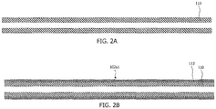
FIGS. 2A-2B are schematic cross-sectional views illustrating a process for forming a first subassembly, in accordance with the present disclosure. -
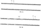
FIGS. 3A-3B are schematic cross-sectional views illustrating a process for forming a second subassembly, in accordance with the present disclosure. -
FIGS. 4A-4B are schematic cross-sectional views illustrating a process for forming an inner electrode assembly, in accordance with the present disclosure. -
FIGS. 5 and 6 are schematic side views illustrating inner electrode assemblies, in accordance with the present disclosure. -
FIGS. 7A-7B are schematic cross-sectional views illustrating a process for forming an inner electrode assembly, in accordance with the present disclosure. -
FIGS. 8A and 8B are schematic cross-sectional and side views, respectively, illustrating an inner electrode assembly, in accordance with the present disclosure. -
FIG. 9 is schematic side view illustrating an inner electrode assembly, in accordance with the present disclosure. - Described herein are devices and systems that comprise one or more shockwave generators comprising shockwave-generating electrodes. The shockwave generators are integral to an inner electrode assembly, which may be sealed within a balloon that is inflated with a conductive fluid (e.g., saline, imaging contrast agent, etc.). The inner electrode assembly may be attached to a source of high voltage pulses, for example, ranging from 100 to 10,000 volts, more typically 100 to 3,000 volts, for various pulse durations, which, without wishing to be bound by theory, may generate rapidly expanding and collapsing bubbles, which in turn create mechanical shockwaves within the balloon. Shockwaves may be mechanically conducted through the fluid and through a wall of the balloon to apply mechanical stress to break apart calcified lesions that may be present on or in the vasculature walls.
-
FIG. 1 is a schematic illustration of ashockwave angioplasty device 100 in accordance with the present disclosure. Thedevice 100 ofFIG. 1 includes aninner electrode assembly 102, an outertubular member 120, and aballoon 130. Theinner electrode assembly 102 includes an innerelongate member 110, an innerconductive layer 112 disposed over the innerelongate member 110, an insulatinglayer 114 disposed over the innerconductive layer 112, an outerconductive layer 116 disposed over the insulatinglayer 114, and an optional additionalinsulating layer 118 disposed over the outerconductive layer 116. - The inner
elongate member 110 may be formed from any suitable material, beneficially a low-friction polymeric material such as, for example, polytetrafluoroethylene (PTFE), fluorinated ethylene propylene (FEP), a copolymer of hexafluoropropylene and tetrafluoroethylene, or high-density polyethylene (HDPE), among other possibilities. The innerelongate member 110 may range, for example, from 0.46 mm to 1.1 mm in outer diameter, among other possibilities. The innerelongate member 110 may include a guide wire lumen 1101 extending along a length of its longitudinal axis. The guide wire lumen 1101 may range, for example, from 0.36 mm to 0.97 mm in diameter, among other possibilities. - The inner
conductive layer 112 and the outerconductive layer 116 may be formed from any material that is able to support the voltages that are required for shockwave generation and to withstand the forces generated by the same. For example, the innerconductive layer 112 and the outerconductive layer 116 may be made of tungsten, nickel, iron, steel, including stainless steel, copper, gold, and the like. The innerconductive layer 112 may range, for example, from 0.00013 mm to 0.0013 mm in thickness, among other possibilities. The outerconductive layer 116 may range, for example, from 0.00013 mm to 0.0013 mm in thickness, among other possibilities. - The insulating
layer 114 may be made of any material having a breakdown voltage that is sufficiently great to withstand voltages that are generated during shockwave generation, for example, fluoropolymers (e.g., PTFE, FEP, etc.), polyethylene terephthalate (PET), polyimide (e.g., Kapton), polyamides, polyamide block polyether copolymers, polyester block copolymers, and the like. As discussed further below, in some embodiments, the insulatinglayer 114 may be formed from a shrinkable material, for example, a heat-shrinkable material. The insulatinglayer 114 may range, for example, form 0.01 mm to 0.08 mm in thickness, among other possibilities. - The optional additional
insulating layer 118 may be formed by the same materials as the insulatinglayer 114, although the electrical demands upon the additional insulatinglayer 118 may not be as great as those associated with insulatinglayer 114. The additional insulatinglayer 118 may range, for example, from 0.01 mm to 0.08 mmin thickness, among other possibilities. - The
inner electrode assembly 102 further includes a plurality of multi-layer apertures 102a (six shown, three of which are labeled), each including a first aperture 114a extending through the insulatinglayer 114, a second aperture 116a extending through the outerconductive layer 116, and a third aperture 118a extending through the optional additionalinsulating layer 118. The first aperture 114a, second aperture 116a, and third aperture 118a are preferably coaxial with one another. Within eachmulti-layer aperture 102a lies an exposed portion of the innerconductive layer 112, which corresponds to aninner electrode 112e. In the embodiment shown, an exposed portion of the outerconductive layer 116 is also contained within eachmulti-layer aperture 102a, corresponding to anouter electrode 116e. By applying a voltage pulse of suitable magnitude and duration across theinner electrode 112e andouter electrode 116e in the presence of a conductive liquid, microbubble creation and collapse may be initiated in the vicinity of eachmulti-layer aperture 102a, leading to the creation of a shockwave, which propagates radially outward from the side of theinner electrode assembly 102. Thus, each aperture inFIG. 1 corresponds to a shockwave generator. Theinner electrode 112e may be a positive electrode and theouter electrode 116e may be a negative electrode or ground electrode, conversely, theouter electrode 116e may be a positive electrode and theinner electrode 112e may be a negative electrode or ground electrode, and so forth. More broadly, a potential difference is established between theinner electrode 112e and theouter electrode 116e that has a magnitude and duration sufficient for shockwave creation. - The multi-layer apertures 102a (and thus the shockwave generators) may be distributed along a longitudinal length of the elongate member. For example, the
multi-layer apertures 102a may be longitudinally spaced by a distance ranging from about 4mm to 25mm, among other possible values. - As an alternative or in addition to being distributed along a longitudinal length of the elongate member, the
multi-layer apertures 102a may be distributed around a circumference of theelongate member 110. For example, themulti-layer apertures 102a may comprise any of the following: - two
multi-layer apertures 102a that are circumferentially offset from one another by an angle of 180°; - three
multi-layer apertures 102a that are circumferentially offset from one another by an angle of 120°; - four
multi-layer apertures 102a that are circumferentially offset from one another by an angle of 90°; - five
multi-layer apertures 102a that are circumferentially offset from one another by an angle of 72°; - six
multi-layer apertures 102a that are circumferentially offset from one another by an angle of 60°; or - eight
multi-layer apertures 102a that are circumferentially offset from one another by an angle of 45°. - It will be understood that a skilled person could also envisage other possible offsets.
- The first aperture 114a, a second aperture 116a and (optional) third aperture 118a may be in the shape of a circle, oval, ellipse, polygon, or any other desired shape. In addition to the thickness of the insulating
layer 114, the nature of the path that the current travels during shockwave formation is influenced by the size and location of the first aperture 114a in the insulatinglayer 114 and the size and location of the second aperture 116a in the outerconductive layer 116. The first aperture 114a in the insulatinglayer 114 may be the same size as the second aperture 116a in the outerconductive layer 116, or may be smaller than the second aperture 116a in the outerconductive layer 116. The third aperture 118a in the optional additionalinsulating layer 118 may be may be the same size as the second aperture 116a in the outerconductive layer 116 or may be larger than the second aperture 116a in the outerconductive layer 116. - In certain beneficial embodiments, the first aperture 114a in the insulating
layer 114 may have a diameter ranging from 0.48 mm to 1.09 mm, among other possible values, the second aperture 116a in the outerconductive layer 116 may have a diameter ranging from 0.51 mm to 1.12 mm, among other possible values, and the third aperture 118a in the optional additionalinsulating layer 118 may have a diameter ranging from 0.53 mm to 1.14 mm, among other possible values. The ratio of the diameters between the first aperture 114a, the second aperture 116a, and the third aperture 118a may be varied to change the nature of the generated shockwave. - In some embodiments, the widths of one or more of the first apertures 114a, second apertures 116a and optional third apertures 118a may vary along a longitudinal length of the
inner electrode assembly 102. For example, aperture widths may be varied along the longitudinal length of theinner electrode assembly 102 such that shockwave generators at the proximal and distal ends of the array deliver higher power shockwaves than those delivered at the center of the array. - The
inner electrode assembly 102 may be used in conjunction with an axially extending catheter that further includes aballoon 130 and an outertubular member 120. The multi-layer apertures 102a (and thus the shockwave generators) of theinner electrode assembly 102 are positioned within theballoon 130. Aproximal end 130p of theballoon 130 is attached to adistal end 120d of the outertubular member 120, and adistal end 130d of theballoon 130 is attached to thedistal end 102d of theinner electrode assembly 102. Although thelayers proximal end 130p of theballoon 130, this is not required. For example, electrical leads can be provided, which extend the length of the catheter and connect the inner and outerconductive layers - The
balloon 130 may be a single layer or multi-layer balloon formed of any suitable material, including polyethylene terephthalate (PET), polyether block amide (e.g., PEBAX), polyamide (e.g., nylon), polyethylene, polyurethane, silicone, and other materials known in the medical balloon art. Theballoon 130 may be attached to the outertubular member 120 and theinner electrode assembly 102 using any method known in the balloon art, including, for example, asuitable adhesive 122. In the embodiment shown, conductive fluid may be introduced into and removed from theballoon 130 through alumen 1201 that lies between theinner electrode assembly 102 and the outertubular member 120. - In this regard, it is noted that devices in accordance with the present disclosure can be used in conjunction with standard balloon manufacturing methods, except that the inner is in the form of an
inner electrode assembly 102, which is constructed so that there are multiple locations in whichmulti-layer apertures 102a are provided, which correspond to shockwave generators. In this regard, when filled with a conductive fluid, themulti-layer apertures 102a provide electrical pathways between the inner and outerconductive layers conductive layers inner electrode assembly 102. The voltage generator is connected to the inner and outerconductive layers inner electrode assembly 102, and applies a suitable voltage across the inner and outerconductive layers inner member 110, which are attached to the inner and outerconductive layers balloon 130. The leads may also be connected to a voltage generator. - Without wishing to be bound by theory, applying a voltage across the inner and outer
conductive layers apertures 102a, which in turn creates micro bubbles of steam. The creation and collapse of the bubbles creates shockwaves which radiate outward from theinner electrode assembly 102. These shockwaves may be used, for example, to disrupt hard calcified lesions in a vessel surrounding theballoon 130, making is easier for theballoon 130 to expand the vessel. The lower pressure required for expansion typically creates a better clinical outcome than POBA (plain old balloon angioplasty). In addition, the breakup of calcified lesions may provide channels for improved uptake of drug from a drug coated balloon. - Shockwave intensity may be controlled in various ways including, for example, by controlling the width of the first apertures 114a, second apertures 116a and third apertures 118a within the
multi-layer apertures 102a, by controlling the thickness of the insulatinglayer 114, by controlling the number of multi-layer apertures 102a (and thus the number of shockwave generators), and by controlling the magnitude and duration of the voltage that is applied by the voltage generator to the inner and outerconductive layers - Note that it may be desirable to minimize the size of the generated bubbles. Embodiments of the invention may, due to the possibility to have a relatively small distance between the inner and outer
conductive layers - Other aspects of the present disclosure pertain to methods of making medical devices for generating shockwaves. The methods include forming
inner electrode assemblies 102 like those described above, in particular,inner electrode assemblies 102 that comprise an innerelongate member 110, an innerconductive layer 112 disposed over the innerelongate member 110, an insulatinglayer 114 disposed over the innerconductive layer 112, an outerconductive layer 116 disposed over the insulatinglayer 114, an optional additionalinsulating layer 118 disposed over the outerconductive layer 116, and one or moremulti-layer apertures 102a extending from an outer surface of theinner electrode assembly 102 down to the innerconductive layer 112 of theinner electrode assembly 102, eachmulti-layer aperture 102a corresponding to a shockwave generator. - In some embodiments, for example, a first subassembly is inserted into a second subassembly, and the first and second subassemblies are then affixed to one another. For example, and with reference to
Figs. 2A-2B , a first subassembly 102s1 may be formed by taking anelongate member 110 as shown inFig. 2A and forming aconductive layer 112 on theelongate member 110 using any suitable method, for example, by depositing aconductive layer 112 on anelongate member 110 using a suitable process, such as physical vapor deposition process, a chemical vapor deposition process, or an electroplating process, or by wrapping aconductive layer 112 around anelongate member 110. In one specific embodiment, a metalconductive layer 112 may be sputter deposited on anelongate member 110 in the form of a PTFE tube. - Referring now to
Figs. 3A-3B , a second subassembly 102s2 may be formed by first creating a tubular member that comprises an insulatinglayer 114 and aconductive layer 116 like that shown inFig. 3A (as well as an optional additional insulating layer, not shown). For example, using any suitable layer formation method, aconductive layer 116 may be formed on an outer surface of an insulatinglayer 114 in the form of a tube of insulating material. For instance, aconductive layer 116 may be deposited on an insulatinglayer 114 in form of a tube of insulating material using a suitable deposition process, such as a physical vapor deposition process, a chemical vapor deposition process, or an electroplating process. In one particular embodiment, a layer of conductive material may be applied to a heat-shrinkable tube of insulating material, for example, a heat-shrinkable FEP tube, a heat-shrinkable PET tube, or nylon, polyolefins, among other possibilities. - Subsequently, apertures 114a, 116a may be formed in the
tubular member - In a subsequent step, the first subassembly 102s1 of
Fig. 2B is positioned inside the second subassembly 102s2 ofFig. 3B to form an assembly like that shown inFig. 4A . Subsequently, the second subassembly 102s2 is shrunk onto the first subassembly 102s1, for example, via heat shrinking or another suitable process, thereby forming aninner subassembly 102 as shown inFig. 4B . A side view of theinner assembly 102 ofFig. 4B is shown inFig. 5 . To enhance the shrinkage process, in some embodiments, the outerconductive layer 116 in the second subassembly 102s2 may be provided over only a portion of the surface of the second subassembly 102s2. For example, the outerconductive layer 116 may be present as a series of conductive lines as shown inFig 6 , or more complex patterns may be employed such as barber-pole and zig-zag patterns (see also, for example,Fig. 8 , discussed further below). - In some embodiments, an
inner electrode assembly 102 like that shown inFig. 7B is created by formingapertures 102a in anassembly 103 like that shown inFig. 7A , which includes an innerelongate member 110, an innerconductive layer 112 disposed over the innerelongate member 110, an insulatinglayer 114 disposed over the innerconductive layer 112, an outerconductive layer 116 disposed over the insulatinglayer 114, and optionally an additional insulating layer (not shown). The apertures may be formed, for example, using any suitable physical, chemical, or physicochemical process, such as mechanical drilling, laser drilling, or masking and etching processes, among others. - In some instances, a process may be selected in which apertures are formed using a process that selectively removes material making up a given layer, relative to another material making up an underlying layer. For example, a process may be selected in which conductive material in the outer
conductive layer 116 is selectively removed relative to insulating material in the insulatinglayer 114 underlying the outerconductive layer 116, such that the insulatinglayer 114 acts as a stop layer when apertures 116a are formed in the outerconductive layer 116. For instance, a process may be selected which removes conductive material from the outerconductive layer 116 at a rate that is at least two times, more beneficially at least four times, even more beneficially at least ten times, the rate at which the process removes insulating material from insulatinglayer 114. - After forming apertures 116a, another process may be selected in which insulating material in the insulating
layer 114 is selectively removed relative to conductive material in the innerconductive layer 112 underlying the insulatinglayer 114, such that the innerconductive layer 112 acts as a stop layer when apertures 114a are formed in the insulatinglayer 114. For instance, a process may be selected which removes insulating material from the insulatinglayer 114 at a rate that is at least two times, more beneficially at least four times, even more beneficially at least ten times the rate at which that process removes conductive material from the innerconductive layer 112. - As a specific example, metallic material may be selectively removed from the outer conductive layer 116 (relative to material in the insulating layer 114) using an eximer laser or using a suitable plasma etching chemistry, whereas insulating material may be selectively removed from the insulating layer 114 (relative to the inner conductive layer 112) using a CO2 laser or an eximer laser or using a suitable plasma etching chemistry. Plasma etching chemistries in which insulating materials (e.g., fluoropolymers) are selectively etched relative to conductive materials (e.g., metals), and in which conductive materials are selectively etched relative to insulating materials, are known in the semiconductor processing industry.
- Using these and other processes, a wide range of aperture sizes and layer layouts may be created, one example of which is an
inner assembly 102 like that shown in schematic cross-sectional and side views inFigs. 8A and 8B , another of which is aninner assembly 102 like that shown in schematic side view inFig. 9 . - Although various embodiments are specifically illustrated and described herein, it will be appreciated that modifications and variations of the present disclosure are covered by the above teachings and are within the purview of the appended claims without departing from the intended scope of the disclosure.
Claims (15)
- A device for treating calcified lesions in blood vessels by way of shockwaves, the device comprising:- a balloon, which balloon is fillable with conductive fluid;- an electrode assembly arranged within the balloon, which electrode assembly comprises:- an inner elongate member extending through the balloon;- a first conductive layer extending through the balloon; and- a second conductive layer extending through the balloon; and- an insulating layer arranged between the first and second conductive layers;- means for propagating shock waves generated by a shockwave generator, in the conductive fluid in the balloon, the means comprising at least one aperture through at least the insulating layer and the second conductive layer.
- The device according to claim 1, wherein the shockwave propagating means comprise an aperture arranged between the first and second conductive layers, whereby the first conductive layer forms a floor of the aperture and whereby an opening in the second conductive layer is arranged opposite the aperture floor, whereby the second conductive layer forms a side of the aperture, wherein the insulating layer preferably has an opening coaxial with the opening in the second conductive layer, whereby the side of the aperture is also formed by the insulating layer.
- The device according to claim 1 or 2wherein the elongate member is an elongate shaft comprising a lumen configured to introduce the conductive fluid into the balloon.
- The device according to any of the preceding claims, wherein the first, or inner, conductive layer is disposed over the inner elongate member, whereby the insulating layer is disposed over the inner conductive layer, whereby the second, or outer, conductive layer is disposed over the insulating layer, and whereby the aperture is formed by a multilayer aperture, which multilayer aperture comprises a first aperture formed by the opening in the insulating layer and a second aperture, formed by the opening in the outer conductive layer,
wherein the first aperture and the second aperture are coaxial with one another, and wherein the multi-layer aperture exposes:a portion of an upper surface of the inner conductive layer at a bottom of the multi-layer aperture, the floor of the aperture, which corresponds to a first electrode; andat least a lateral surface of the outer conductive layer surrounding the multi-layer aperture, the side of the aperture, which corresponds to a second electrode. - The device of claim 4, wherein a width of the first aperture is the same as a width of the second aperture, or wherein a width of the first aperture is different from a width of the second aperture; and/or
comprising a plurality of said multi-layer apertures, and/or
wherein at least some of the plurality of said multi-layer apertures are circumferentially offset from each other, wherein at least some of the plurality of said multi-layer apertures are longitudinally offset from each other, or wherein at least some of the plurality of said multi-layer apertures are both circumferentially and longitudinally offset from each other; and/or
wherein the plurality of said multi-layer apertures comprises:two multi-layer apertures that are circumferentially offset from one another by an angle of 180°;three multi-layer apertures that are circumferentially offset from one another by an angle of 120°;four multi-layer apertures that are circumferentially offset from one another by an angle of 90°;five multi-layer apertures that are circumferentially offset from one another by an angle of 72°;six multi-layer apertures that are circumferentially offset from one another by an angle of 60°; oreight multi-layer apertures that are circumferentially offset from one another by an angle of 45°. - The device of any one of the preceding claims, further comprising an additional insulating layer disposed over at least a portion of the outer conductive layer; wherein the multi-layer aperture preferably comprises a third aperture formed in the additional insulating layer and wherein the third aperture is coaxial with the first aperture and the second aperture.
- The device of any one of claims 3-6, wherein a proximal end of the balloon is attached to a distal end of the elongate member, and wherein a distal end of the balloon is attached to a distal end of the inner electrode assembly;, and/or wherein the inner elongate member comprises a lumen, preferably wherein a guidewire is disposed in the lumen.
- A system comprising:a device in accordance with any one of claims 1-7; anda shockwave generator, which shockwave generator is preferably a voltage generator in electrical connection with the inner and outer conductive layers and configured to apply a voltage pulse across the inner and outer conductive layers that is of sufficient magnitude and duration to generate a shock wave.
- A method of making a medical device suitable for generating shockwaves, said method comprising:creating an electrode assembly comprising an inner elongate member, a first conductive layer, a second conductive layer and an insulating layer arranged between the first and second conductive layers; andarranging means for propagating shockwaves with the first and second conductive layers, the means comprising at least one aperture through at least the insulating layer and the second conductive layer.
- The method according to claim 9,
wherein the step of arranging the shockwave propagating means comprises arranging an aperture between the first and second conductive layers, which aperture is formed by the first conductive layer forming a floor of the aperture and an opening in the second conductive layer opposite the aperture floor, whereby the second conductive layer forms a side of the aperture; and/or
wherein, in the insulating layer, an opening is arranged coaxial with the opening in the second conductive layer so that the side of the aperture is also formed by the insulating layer. - The method of any of claims 9-10, whereby the first, or inner, conductive layer is disposed over the inner elongate member, whereby the insulating layer is disposed over the inner conductive layer, whereby the second, or outer, conductive layer is disposed over the insulating layer, and whereby the aperture is formed by a multilayer aperture, which multilayer aperture comprises a first aperture formed by the opening in the insulating layer and a second aperture, formed by the opening in the outer conductive layer, wherein the first aperture and the second aperture are coaxial with one another, and wherein the multi-layer aperture exposes:a portion of an upper surface of the inner conductive layer at a bottom of the multi-layer aperture, the floor of the aperture, which corresponds to a first electrode; andat least a lateral surface of the outer conductive layer surrounding the multi-layer aperture, the side of the aperture, which corresponds to a second electrode.
- The method of claim 11,
further comprising incorporating the inner electrode assembly into a balloon catheter that comprises a balloon and an elongate shaft comprising a lumen that is configured to introduce conductive fluid into the balloon, such that the multi-layer aperture of the inner electrode assembly is positioned inside the balloon, and/or
wherein forming the electrode assembly comprises:inserting a first subassembly into a second subassembly, the first subassembly comprising the inner elongate member and the inner conductive layer disposed over the inner elongate member, and the second subassembly comprising the insulating layer, the outer conductive layer disposed over the insulating layer, the first aperture extending through the insulating layer, and the second aperture extending through the outer conductive layer; andaffixing the first subassembly to the second subassembly, preferably wherein the first subassembly is affixed to the second subassembly by shrinking the second subassembly onto a surface of the first subassembly. - The method of any claim 11 or 12 , wherein forming the inner electrode assembly comprises forming the multi-layer aperture in an assembly that comprises the inner elongate member, the inner conductive layer disposed over the inner elongate member, the insulating layer disposed over the inner conductive layer, and the outer conductive layer disposed over the insulating layer.
- The method of claim 13, wherein forming the multi-layer aperture comprises:(i) forming the second aperture in the outer conductive layer by a first process that removes a material of the outer conductive layer, thereby exposing the lateral surface of the outer conductive layer; and(ii) forming the first aperture in the insulating layer using a second process that removes a material of the insulating layer, thereby exposing an upper surface of the inner conductive layer, .
- The method of claim 14, wherein the first process is one that selectively removes the material of the outer conductive layer relative to the material of the insulating layer, and wherein the second process is one that selectively removes the material of the insulating layer relative to a material of the inner conductive layer.
Applications Claiming Priority (2)
| Application Number | Priority Date | Filing Date | Title |
|---|---|---|---|
| US201762537126P | 2017-07-26 | 2017-07-26 | |
| NL2019807A NL2019807B1 (en) | 2017-10-26 | 2017-10-26 | Shockwave generating device |
Publications (2)
| Publication Number | Publication Date |
|---|---|
| EP3434209A1 true EP3434209A1 (en) | 2019-01-30 |
| EP3434209B1 EP3434209B1 (en) | 2020-12-23 |
Family
ID=60382565
Family Applications (1)
| Application Number | Title | Priority Date | Filing Date |
|---|---|---|---|
| EP18185152.8A Active EP3434209B1 (en) | 2017-07-26 | 2018-07-24 | Shockwave generating device |
Country Status (4)
| Country | Link |
|---|---|
| US (1) | US10786267B2 (en) |
| EP (1) | EP3434209B1 (en) |
| CN (1) | CN109303586B (en) |
| NL (1) | NL2019807B1 (en) |
Cited By (5)
| Publication number | Priority date | Publication date | Assignee | Title |
|---|---|---|---|---|
| WO2021061451A1 (en) * | 2019-09-24 | 2021-04-01 | Shockwave Medical, Inc. | Lesion crossing shock wave catheter |
| US11602363B2 (en) | 2017-06-19 | 2023-03-14 | Shockwave Medical, Inc. | Device and method for generating forward directed shock waves |
| US12035932B1 (en) | 2023-04-21 | 2024-07-16 | Shockwave Medical, Inc. | Intravascular lithotripsy catheter with slotted emitter bands |
| US12232755B2 (en) | 2020-12-11 | 2025-02-25 | Shockwave Medical, Inc. | Lesion crossing shock wave catheter |
| EP4643795A4 (en) * | 2022-12-29 | 2026-04-15 | Shanghai Bluesail Boyuan Medical Tech Co Ltd | Shockwave Electrode Assembly and Balloon Catheter Device |
Families Citing this family (58)
| Publication number | Priority date | Publication date | Assignee | Title |
|---|---|---|---|---|
| US11266817B2 (en) * | 2018-10-25 | 2022-03-08 | Medtronic Vascular, Inc. | Cavitation catheter |
| US12402946B2 (en) | 2019-06-19 | 2025-09-02 | Boston Scientific Scimed, Inc. | Breakdown of laser pulse energy for breakup of vascular calcium |
| WO2020256898A1 (en) | 2019-06-19 | 2020-12-24 | Boston Scientific Scimed, Inc. | Balloon surface photoacoustic pressure wave generation to disrupt vascular lesions |
| US11717139B2 (en) | 2019-06-19 | 2023-08-08 | Bolt Medical, Inc. | Plasma creation via nonaqueous optical breakdown of laser pulse energy for breakup of vascular calcium |
| US11660427B2 (en) | 2019-06-24 | 2023-05-30 | Boston Scientific Scimed, Inc. | Superheating system for inertial impulse generation to disrupt vascular lesions |
| US20200406010A1 (en) | 2019-06-26 | 2020-12-31 | Boston Scientific Scimed, Inc. | Side light direction plasma system to disrupt vascular lesions |
| CN110811762A (en) * | 2019-08-08 | 2020-02-21 | 谱创医疗科技(上海)有限公司 | Shock wave enhanced drug delivery catheter |
| US11583339B2 (en) | 2019-10-31 | 2023-02-21 | Bolt Medical, Inc. | Asymmetrical balloon for intravascular lithotripsy device and method |
| US12102384B2 (en) | 2019-11-13 | 2024-10-01 | Bolt Medical, Inc. | Dynamic intravascular lithotripsy device with movable energy guide |
| US12274497B2 (en) | 2019-12-18 | 2025-04-15 | Bolt Medical, Inc. | Multiplexer for laser-driven intravascular lithotripsy device |
| US12446961B2 (en) | 2020-02-10 | 2025-10-21 | Bolt Medical, Inc. | System and method for pressure monitoring within a catheter system |
| US11672599B2 (en) | 2020-03-09 | 2023-06-13 | Bolt Medical, Inc. | Acoustic performance monitoring system and method within intravascular lithotripsy device |
| US12611253B2 (en) | 2020-03-18 | 2026-04-28 | Boston Scientific Scimed, Inc. | Optical analyzer assembly and method for intravascular lithotripsy device |
| US11707323B2 (en) | 2020-04-03 | 2023-07-25 | Bolt Medical, Inc. | Electrical analyzer assembly for intravascular lithotripsy device |
| US20210353359A1 (en) | 2020-05-12 | 2021-11-18 | Bolt Medical, Inc. | Active alignment system and method for optimizing optical coupling of multiplexer for laser-driven intravascular lithotripsy device |
| CN111568500A (en) * | 2020-05-26 | 2020-08-25 | 王志玉 | Blood vessel recanalization system for cardiovascular stenosis lesion |
| US12295654B2 (en) | 2020-06-03 | 2025-05-13 | Boston Scientific Scimed, Inc. | System and method for maintaining balloon integrity within intravascular lithotripsy device with plasma generator |
| US12207870B2 (en) | 2020-06-15 | 2025-01-28 | Boston Scientific Scimed, Inc. | Spectroscopic tissue identification for balloon intravascular lithotripsy guidance |
| CN118750097A (en) * | 2020-07-31 | 2024-10-11 | 深圳市赛禾医疗技术有限公司 | A pressure wave balloon catheter |
| CN112220526B (en) * | 2020-12-10 | 2021-04-02 | 上海百心安生物技术股份有限公司 | Pulse balloon and using method |
| US12016610B2 (en) | 2020-12-11 | 2024-06-25 | Bolt Medical, Inc. | Catheter system for valvuloplasty procedure |
| CN112869825A (en) * | 2021-01-06 | 2021-06-01 | 苏州中荟医疗科技有限公司 | Electrode device for generating seismic waves and using method |
| US11672585B2 (en) | 2021-01-12 | 2023-06-13 | Bolt Medical, Inc. | Balloon assembly for valvuloplasty catheter system |
| EP4277548B1 (en) | 2021-01-12 | 2025-06-04 | Bolt Medical, Inc. | Balloon assembly for valvuloplasty catheter system |
| CN114869400B (en) * | 2021-02-05 | 2025-02-18 | 沛嘉医疗科技(苏州)有限公司 | Electrode for shock wave device and shock wave device for treating heart valve or blood vessel calcification |
| US12611219B2 (en) * | 2021-02-05 | 2026-04-28 | Peijia Medical (Suzhou) Co., Ltd. | Electrode assembly and shock wave apparatus using the electrode assembly |
| CN114869399B (en) * | 2021-02-05 | 2025-03-07 | 沛嘉医疗科技(苏州)有限公司 | Electrode assembly and shock wave device using the same |
| CN114869401B (en) * | 2021-02-05 | 2023-09-22 | 沛嘉医疗科技(苏州)有限公司 | Shock wave device |
| CN112971914B (en) * | 2021-02-09 | 2022-08-02 | 哈尔滨医科大学 | Intravascular perfusion shock wave lithotripsy catheter system |
| US11944331B2 (en) | 2021-02-26 | 2024-04-02 | Fastwave Medical Inc. | Intravascular lithotripsy |
| US11911056B2 (en) | 2021-02-26 | 2024-02-27 | Fastwave Medical Inc. | Intravascular lithotripsy |
| US11484327B2 (en) | 2021-02-26 | 2022-11-01 | Fastwave Medical Inc. | Intravascular lithotripsy |
| CN113317845B (en) * | 2021-03-23 | 2023-03-14 | 上海百心安生物技术股份有限公司 | Pulse saccule with grounding treatment on inner wall |
| CN112914719B (en) * | 2021-03-24 | 2025-11-11 | 上海微创旋律医疗科技有限公司 | Electrode saccule catheter and high-voltage generation processing device |
| US11648057B2 (en) | 2021-05-10 | 2023-05-16 | Bolt Medical, Inc. | Optical analyzer assembly with safety shutdown system for intravascular lithotripsy device |
| US11806075B2 (en) | 2021-06-07 | 2023-11-07 | Bolt Medical, Inc. | Active alignment system and method for laser optical coupling |
| CN114886502B (en) * | 2021-06-07 | 2025-03-14 | 上海百心安生物技术股份有限公司 | A pulse balloon with capacitor and its application |
| CN113367768B (en) * | 2021-06-11 | 2023-03-21 | 南京欣科医疗器械有限公司 | Shock wave sacculus pipe with integrated electric field generating mechanism |
| CN113648048A (en) | 2021-07-15 | 2021-11-16 | 深圳市赛禾医疗技术有限公司 | Shock wave balloon catheter system with controllable discharge |
| US12622716B2 (en) | 2021-08-05 | 2026-05-12 | Cardiovascular Systems, Inc. | Systems, devices and methods for generating patterns of voltage pulses and electrical arcs between spaced-apart electrode pairs in intravascular lithotripsy |
| CN113633346B (en) * | 2021-08-31 | 2024-05-03 | 苏州中荟医疗科技有限公司 | Electrode device and shock wave generating system |
| AU2022371178B2 (en) | 2021-10-19 | 2024-08-29 | Shockwave Medical, Inc. | Intravascular lithotripsy catheter with interfering shock waves |
| CN113855163B (en) * | 2021-11-09 | 2024-03-22 | 上海蓝帆博元医疗科技有限公司 | Shock wave electrode assembly, balloon catheter device and medical equipment |
| DE112022005708T5 (en) * | 2021-11-30 | 2024-11-14 | Shockwave Medical, Inc. | ELECTRODE DESIGN FOR DIRECTED LITHOTRIPSY CATHETER |
| CN114305652A (en) * | 2021-12-09 | 2022-04-12 | 深圳先进技术研究院 | Micropore electrode for blood vessel calcification breaking treatment |
| US11839391B2 (en) | 2021-12-14 | 2023-12-12 | Bolt Medical, Inc. | Optical emitter housing assembly for intravascular lithotripsy device |
| US20230405268A1 (en) * | 2022-01-11 | 2023-12-21 | Covellus Llc | Intravascular lithotripsy catheter |
| US12533184B2 (en) | 2022-04-02 | 2026-01-27 | Boston Scientific Scimed, Inc. | Optical connector assembly for intravascular lithotripsy device |
| CN114587500A (en) * | 2022-04-06 | 2022-06-07 | 上海百心安生物技术股份有限公司 | Transduction pulse sacculus expansion pipe |
| CN114903558B (en) * | 2022-05-19 | 2023-11-10 | 杭州天路医疗器械有限公司 | Shock wave generating device for molding body cavity channel |
| CA3254367A1 (en) | 2022-06-01 | 2023-12-07 | Fastwave Medical Inc. | Intravascular lithotripsy |
| US12193738B2 (en) | 2022-06-01 | 2025-01-14 | Fastwave Medical Inc. | Intravascular lithotripsy |
| CN115068060A (en) * | 2022-08-18 | 2022-09-20 | 深圳北芯医疗科技有限公司 | Shock wave generating assembly and balloon catheter |
| CN115245373B (en) * | 2022-09-26 | 2023-06-23 | 上海百心安生物技术股份有限公司 | Pulse saccule dilating catheter capable of being crushed uniformly |
| AU2023366680A1 (en) * | 2022-10-25 | 2025-05-01 | Spectrumedics Medical Technology (Shanghai) Co., Ltd. | Electrode assemblies for shockwave generating catheters |
| CN117338373B (en) * | 2023-09-14 | 2024-08-20 | 深圳高性能医疗器械国家研究院有限公司 | Shock wave balloon catheter excitation method and shock wave balloon catheter system |
| US12402901B2 (en) | 2024-02-08 | 2025-09-02 | IV-X Medical, LLC | Intravascular lithotripsy catheter |
| CN118356232B (en) * | 2024-06-18 | 2024-11-15 | 苏州中荟医疗科技有限公司 | An electrode catheter structure capable of superimposing energy release |
Citations (4)
| Publication number | Priority date | Publication date | Assignee | Title |
|---|---|---|---|---|
| GB1082397A (en) * | 1966-04-06 | 1967-09-06 | Oleg Gavrilovich Balaev | Instrument for crushing stones in the urinary bladder |
| US20140005576A1 (en) * | 2012-06-27 | 2014-01-02 | Shockwave Medical, Inc. | Shock wave balloon catheter with multiple shock wave sources |
| US20140039513A1 (en) * | 2012-08-06 | 2014-02-06 | Shockwave Medical, Inc. | Low profile electrodes for an angioplasty shock wave catheter |
| US20150039002A1 (en) * | 2013-07-31 | 2015-02-05 | Shockwave Medical, Inc. | Angioplasty balloon |
Family Cites Families (27)
| Publication number | Priority date | Publication date | Assignee | Title |
|---|---|---|---|---|
| US5055101A (en) * | 1983-10-31 | 1991-10-08 | Catheter Research, Inc. | Variable shape guide apparatus |
| ATE178218T1 (en) | 1993-02-05 | 1999-04-15 | Joe W And Dorothy Dorsett Brow | ULTRASONIC BALLOON CATHETER FOR ANGIOPLASTY |
| US6123923A (en) | 1997-12-18 | 2000-09-26 | Imarx Pharmaceutical Corp. | Optoacoustic contrast agents and methods for their use |
| US6685732B2 (en) * | 1998-03-31 | 2004-02-03 | Innercool Therapies, Inc. | Method and device for performing cooling- or cryo-therapies for, e.g., angioplasty with reduced restenosis or pulmonary vein cell necrosis to inhibit atrial fibrillation employing microporous balloon |
| US6610007B2 (en) | 2000-04-03 | 2003-08-26 | Neoguide Systems, Inc. | Steerable segmented endoscope and method of insertion |
| JP4391221B2 (en) | 2003-12-22 | 2009-12-24 | 有限会社日本エレクテル | High frequency heating balloon catheter |
| US20070088380A1 (en) * | 2005-10-14 | 2007-04-19 | Endocross Ltd. | Balloon catheter system for treating vascular occlusions |
| WO2007136599A2 (en) * | 2006-05-16 | 2007-11-29 | Wilson-Cook Medical Inc. | Balloon cuff |
| US9283034B2 (en) * | 2007-09-26 | 2016-03-15 | Retrovascular, Inc. | Recanalization system using radiofrequency energy |
| WO2009053839A2 (en) * | 2007-10-22 | 2009-04-30 | Endocross Ltd. | Balloons and balloon catheter systems for treating vascular occlusions |
| AU2009257368B2 (en) | 2008-06-13 | 2014-09-11 | Djt, Llc | Shockwave balloon catheter system |
| US9180280B2 (en) | 2008-11-04 | 2015-11-10 | Shockwave Medical, Inc. | Drug delivery shockwave balloon catheter system |
| US9044618B2 (en) | 2008-11-05 | 2015-06-02 | Shockwave Medical, Inc. | Shockwave valvuloplasty catheter system |
| ES2976564T3 (en) | 2011-02-01 | 2024-08-05 | Channel Medsystems Inc | Apparatus for cryogenic treatment of a body cavity or lumen |
| TWI558702B (en) | 2011-02-21 | 2016-11-21 | 普雷辛肯公司 | Solid forms of a pharmaceutically active substance |
| US10016579B2 (en) | 2011-06-23 | 2018-07-10 | W.L. Gore & Associates, Inc. | Controllable inflation profile balloon cover apparatus |
| US8574247B2 (en) | 2011-11-08 | 2013-11-05 | Shockwave Medical, Inc. | Shock wave valvuloplasty device with moveable shock wave generator |
| US9381039B2 (en) * | 2012-03-21 | 2016-07-05 | Medtronic, Inc. | Filling methods and apparatus for implanted medical therapy delivery devices |
| CN202666191U (en) * | 2012-07-04 | 2013-01-16 | 青岛大学医学院附属医院 | Esophagus balloon electrode conduit |
| JP6164705B2 (en) | 2012-08-06 | 2017-07-19 | ショックウェーブ メディカル, インコーポレイテッド | Shock wave catheter |
| CN104519809B (en) | 2012-08-08 | 2018-01-02 | 冲击波医疗公司 | Shockwave valvuloplasty with multiple balloons |
| US9237984B2 (en) | 2012-08-10 | 2016-01-19 | Shockwave Medical, Inc. | Shockwave nerve therapy system and method |
| US9138249B2 (en) | 2012-08-17 | 2015-09-22 | Shockwave Medical, Inc. | Shock wave catheter system with arc preconditioning |
| WO2014032016A1 (en) * | 2012-08-24 | 2014-02-27 | Boston Scientific Scimed, Inc. | Intravascular catheter with a balloon comprising separate microporous regions |
| US9333000B2 (en) | 2012-09-13 | 2016-05-10 | Shockwave Medical, Inc. | Shockwave catheter system with energy control |
| US9730715B2 (en) | 2014-05-08 | 2017-08-15 | Shockwave Medical, Inc. | Shock wave guide wire |
| US20160135828A1 (en) | 2014-11-14 | 2016-05-19 | Shockwave Medical, Inc. | Shock wave valvuloplasty device and methods |
-
2017
- 2017-10-26 NL NL2019807A patent/NL2019807B1/en active
-
2018
- 2018-07-24 EP EP18185152.8A patent/EP3434209B1/en active Active
- 2018-07-25 US US16/045,180 patent/US10786267B2/en active Active
- 2018-07-26 CN CN201810836179.2A patent/CN109303586B/en active Active
Patent Citations (4)
| Publication number | Priority date | Publication date | Assignee | Title |
|---|---|---|---|---|
| GB1082397A (en) * | 1966-04-06 | 1967-09-06 | Oleg Gavrilovich Balaev | Instrument for crushing stones in the urinary bladder |
| US20140005576A1 (en) * | 2012-06-27 | 2014-01-02 | Shockwave Medical, Inc. | Shock wave balloon catheter with multiple shock wave sources |
| US20140039513A1 (en) * | 2012-08-06 | 2014-02-06 | Shockwave Medical, Inc. | Low profile electrodes for an angioplasty shock wave catheter |
| US20150039002A1 (en) * | 2013-07-31 | 2015-02-05 | Shockwave Medical, Inc. | Angioplasty balloon |
Cited By (11)
| Publication number | Priority date | Publication date | Assignee | Title |
|---|---|---|---|---|
| US11602363B2 (en) | 2017-06-19 | 2023-03-14 | Shockwave Medical, Inc. | Device and method for generating forward directed shock waves |
| US11950793B2 (en) | 2017-06-19 | 2024-04-09 | Shockwave Medical, Inc. | Device and method for generating forward directed shock waves |
| US12232754B2 (en) | 2017-06-19 | 2025-02-25 | Shockwave Medical, Inc. | Device and method for generating forward directed shock waves |
| WO2021061451A1 (en) * | 2019-09-24 | 2021-04-01 | Shockwave Medical, Inc. | Lesion crossing shock wave catheter |
| EP4454575A3 (en) * | 2019-09-24 | 2025-01-15 | Shockwave Medical, Inc. | Lesion crossing shock wave catheter |
| US12274460B2 (en) | 2019-09-24 | 2025-04-15 | Shockwave Medical, Inc. | Lesion crossing shock wave catheter |
| AU2020354360B2 (en) * | 2019-09-24 | 2026-03-05 | Shockwave Medical, Inc. | Lesion crossing shock wave catheter |
| US12232755B2 (en) | 2020-12-11 | 2025-02-25 | Shockwave Medical, Inc. | Lesion crossing shock wave catheter |
| EP4643795A4 (en) * | 2022-12-29 | 2026-04-15 | Shanghai Bluesail Boyuan Medical Tech Co Ltd | Shockwave Electrode Assembly and Balloon Catheter Device |
| US12035932B1 (en) | 2023-04-21 | 2024-07-16 | Shockwave Medical, Inc. | Intravascular lithotripsy catheter with slotted emitter bands |
| WO2024220116A1 (en) * | 2023-04-21 | 2024-10-24 | Shockwave Medical, Inc. | Intravascular lithotripsy catheter with slotted emitter bands |
Also Published As
| Publication number | Publication date |
|---|---|
| EP3434209B1 (en) | 2020-12-23 |
| CN109303586A (en) | 2019-02-05 |
| US10786267B2 (en) | 2020-09-29 |
| NL2019807B1 (en) | 2019-05-06 |
| CN109303586B (en) | 2021-07-16 |
| US20190029703A1 (en) | 2019-01-31 |
Similar Documents
| Publication | Publication Date | Title |
|---|---|---|
| EP3434209B1 (en) | Shockwave generating device | |
| US20240268842A1 (en) | Lesion crossing shock wave catheter | |
| US12232755B2 (en) | Lesion crossing shock wave catheter | |
| JP7573603B2 (en) | Thin electrodes for shockwave catheters. | |
| EP3643259B1 (en) | Cavitation catheter | |
| US9867629B2 (en) | Angioplasty balloon | |
| JP5636363B2 (en) | Shock wave balloon catheter device | |
| EP0754074A1 (en) | Method and apparatus for performing multiple procedures | |
| US20250186074A1 (en) | Lesion crossing shock wave catheter | |
| US20260069296A1 (en) | Multi-modality balloon catheter including lithotripsy balloon | |
| CN116867445A (en) | Lesion-penetrating shockwave catheter |
Legal Events
| Date | Code | Title | Description |
|---|---|---|---|
| PUAI | Public reference made under article 153(3) epc to a published international application that has entered the european phase |
Free format text: ORIGINAL CODE: 0009012 |
|
| STAA | Information on the status of an ep patent application or granted ep patent |
Free format text: STATUS: REQUEST FOR EXAMINATION WAS MADE |
|
| STAA | Information on the status of an ep patent application or granted ep patent |
Free format text: STATUS: EXAMINATION IS IN PROGRESS |
|
| 17P | Request for examination filed |
Effective date: 20180724 |
|
| AK | Designated contracting states |
Kind code of ref document: A1 Designated state(s): AL AT BE BG CH CY CZ DE DK EE ES FI FR GB GR HR HU IE IS IT LI LT LU LV MC MK MT NL NO PL PT RO RS SE SI SK SM TR |
|
| AX | Request for extension of the european patent |
Extension state: BA ME |
|
| 17Q | First examination report despatched |
Effective date: 20190116 |
|
| GRAP | Despatch of communication of intention to grant a patent |
Free format text: ORIGINAL CODE: EPIDOSNIGR1 |
|
| STAA | Information on the status of an ep patent application or granted ep patent |
Free format text: STATUS: GRANT OF PATENT IS INTENDED |
|
| INTG | Intention to grant announced |
Effective date: 20200916 |
|
| RIN1 | Information on inventor provided before grant (corrected) |
Inventor name: HORN, DANIEL J. Inventor name: WASDYKE, JOEL M. Inventor name: LOMICKA, AARON |
|
| GRAS | Grant fee paid |
Free format text: ORIGINAL CODE: EPIDOSNIGR3 |
|
| GRAA | (expected) grant |
Free format text: ORIGINAL CODE: 0009210 |
|
| STAA | Information on the status of an ep patent application or granted ep patent |
Free format text: STATUS: THE PATENT HAS BEEN GRANTED |
|
| AK | Designated contracting states |
Kind code of ref document: B1 Designated state(s): AL AT BE BG CH CY CZ DE DK EE ES FI FR GB GR HR HU IE IS IT LI LT LU LV MC MK MT NL NO PL PT RO RS SE SI SK SM TR |
|
| REG | Reference to a national code |
Ref country code: GB Ref legal event code: FG4D |
|
| REG | Reference to a national code |
Ref country code: DE Ref legal event code: R096 Ref document number: 602018011019 Country of ref document: DE |
|
| REG | Reference to a national code |
Ref country code: AT Ref legal event code: REF Ref document number: 1346937 Country of ref document: AT Kind code of ref document: T Effective date: 20210115 |
|
| REG | Reference to a national code |
Ref country code: IE Ref legal event code: FG4D |
|
| PG25 | Lapsed in a contracting state [announced via postgrant information from national office to epo] |
Ref country code: RS Free format text: LAPSE BECAUSE OF FAILURE TO SUBMIT A TRANSLATION OF THE DESCRIPTION OR TO PAY THE FEE WITHIN THE PRESCRIBED TIME-LIMIT Effective date: 20201223 Ref country code: FI Free format text: LAPSE BECAUSE OF FAILURE TO SUBMIT A TRANSLATION OF THE DESCRIPTION OR TO PAY THE FEE WITHIN THE PRESCRIBED TIME-LIMIT Effective date: 20201223 Ref country code: GR Free format text: LAPSE BECAUSE OF FAILURE TO SUBMIT A TRANSLATION OF THE DESCRIPTION OR TO PAY THE FEE WITHIN THE PRESCRIBED TIME-LIMIT Effective date: 20210324 Ref country code: NO Free format text: LAPSE BECAUSE OF FAILURE TO SUBMIT A TRANSLATION OF THE DESCRIPTION OR TO PAY THE FEE WITHIN THE PRESCRIBED TIME-LIMIT Effective date: 20210323 |
|
| REG | Reference to a national code |
Ref country code: AT Ref legal event code: MK05 Ref document number: 1346937 Country of ref document: AT Kind code of ref document: T Effective date: 20201223 |
|
| REG | Reference to a national code |
Ref country code: NL Ref legal event code: MP Effective date: 20201223 |
|
| PG25 | Lapsed in a contracting state [announced via postgrant information from national office to epo] |
Ref country code: BG Free format text: LAPSE BECAUSE OF FAILURE TO SUBMIT A TRANSLATION OF THE DESCRIPTION OR TO PAY THE FEE WITHIN THE PRESCRIBED TIME-LIMIT Effective date: 20210323 Ref country code: LV Free format text: LAPSE BECAUSE OF FAILURE TO SUBMIT A TRANSLATION OF THE DESCRIPTION OR TO PAY THE FEE WITHIN THE PRESCRIBED TIME-LIMIT Effective date: 20201223 Ref country code: SE Free format text: LAPSE BECAUSE OF FAILURE TO SUBMIT A TRANSLATION OF THE DESCRIPTION OR TO PAY THE FEE WITHIN THE PRESCRIBED TIME-LIMIT Effective date: 20201223 |
|
| PG25 | Lapsed in a contracting state [announced via postgrant information from national office to epo] |
Ref country code: NL Free format text: LAPSE BECAUSE OF FAILURE TO SUBMIT A TRANSLATION OF THE DESCRIPTION OR TO PAY THE FEE WITHIN THE PRESCRIBED TIME-LIMIT Effective date: 20201223 Ref country code: HR Free format text: LAPSE BECAUSE OF FAILURE TO SUBMIT A TRANSLATION OF THE DESCRIPTION OR TO PAY THE FEE WITHIN THE PRESCRIBED TIME-LIMIT Effective date: 20201223 |
|
| REG | Reference to a national code |
Ref country code: LT Ref legal event code: MG9D |
|
| PG25 | Lapsed in a contracting state [announced via postgrant information from national office to epo] |
Ref country code: SM Free format text: LAPSE BECAUSE OF FAILURE TO SUBMIT A TRANSLATION OF THE DESCRIPTION OR TO PAY THE FEE WITHIN THE PRESCRIBED TIME-LIMIT Effective date: 20201223 Ref country code: EE Free format text: LAPSE BECAUSE OF FAILURE TO SUBMIT A TRANSLATION OF THE DESCRIPTION OR TO PAY THE FEE WITHIN THE PRESCRIBED TIME-LIMIT Effective date: 20201223 Ref country code: CZ Free format text: LAPSE BECAUSE OF FAILURE TO SUBMIT A TRANSLATION OF THE DESCRIPTION OR TO PAY THE FEE WITHIN THE PRESCRIBED TIME-LIMIT Effective date: 20201223 Ref country code: SK Free format text: LAPSE BECAUSE OF FAILURE TO SUBMIT A TRANSLATION OF THE DESCRIPTION OR TO PAY THE FEE WITHIN THE PRESCRIBED TIME-LIMIT Effective date: 20201223 Ref country code: PT Free format text: LAPSE BECAUSE OF FAILURE TO SUBMIT A TRANSLATION OF THE DESCRIPTION OR TO PAY THE FEE WITHIN THE PRESCRIBED TIME-LIMIT Effective date: 20210423 Ref country code: RO Free format text: LAPSE BECAUSE OF FAILURE TO SUBMIT A TRANSLATION OF THE DESCRIPTION OR TO PAY THE FEE WITHIN THE PRESCRIBED TIME-LIMIT Effective date: 20201223 Ref country code: LT Free format text: LAPSE BECAUSE OF FAILURE TO SUBMIT A TRANSLATION OF THE DESCRIPTION OR TO PAY THE FEE WITHIN THE PRESCRIBED TIME-LIMIT Effective date: 20201223 |
|
| PG25 | Lapsed in a contracting state [announced via postgrant information from national office to epo] |
Ref country code: AT Free format text: LAPSE BECAUSE OF FAILURE TO SUBMIT A TRANSLATION OF THE DESCRIPTION OR TO PAY THE FEE WITHIN THE PRESCRIBED TIME-LIMIT Effective date: 20201223 Ref country code: PL Free format text: LAPSE BECAUSE OF FAILURE TO SUBMIT A TRANSLATION OF THE DESCRIPTION OR TO PAY THE FEE WITHIN THE PRESCRIBED TIME-LIMIT Effective date: 20201223 |
|
| REG | Reference to a national code |
Ref country code: DE Ref legal event code: R097 Ref document number: 602018011019 Country of ref document: DE |
|
| PG25 | Lapsed in a contracting state [announced via postgrant information from national office to epo] |
Ref country code: IS Free format text: LAPSE BECAUSE OF FAILURE TO SUBMIT A TRANSLATION OF THE DESCRIPTION OR TO PAY THE FEE WITHIN THE PRESCRIBED TIME-LIMIT Effective date: 20210423 |
|
| PG25 | Lapsed in a contracting state [announced via postgrant information from national office to epo] |
Ref country code: IT Free format text: LAPSE BECAUSE OF FAILURE TO SUBMIT A TRANSLATION OF THE DESCRIPTION OR TO PAY THE FEE WITHIN THE PRESCRIBED TIME-LIMIT Effective date: 20201223 Ref country code: AL Free format text: LAPSE BECAUSE OF FAILURE TO SUBMIT A TRANSLATION OF THE DESCRIPTION OR TO PAY THE FEE WITHIN THE PRESCRIBED TIME-LIMIT Effective date: 20201223 |
|
| PLBE | No opposition filed within time limit |
Free format text: ORIGINAL CODE: 0009261 |
|
| STAA | Information on the status of an ep patent application or granted ep patent |
Free format text: STATUS: NO OPPOSITION FILED WITHIN TIME LIMIT |
|
| PG25 | Lapsed in a contracting state [announced via postgrant information from national office to epo] |
Ref country code: DK Free format text: LAPSE BECAUSE OF FAILURE TO SUBMIT A TRANSLATION OF THE DESCRIPTION OR TO PAY THE FEE WITHIN THE PRESCRIBED TIME-LIMIT Effective date: 20201223 |
|
| 26N | No opposition filed |
Effective date: 20210924 |
|
| PG25 | Lapsed in a contracting state [announced via postgrant information from national office to epo] |
Ref country code: ES Free format text: LAPSE BECAUSE OF FAILURE TO SUBMIT A TRANSLATION OF THE DESCRIPTION OR TO PAY THE FEE WITHIN THE PRESCRIBED TIME-LIMIT Effective date: 20201223 |
|
| PG25 | Lapsed in a contracting state [announced via postgrant information from national office to epo] |
Ref country code: SI Free format text: LAPSE BECAUSE OF FAILURE TO SUBMIT A TRANSLATION OF THE DESCRIPTION OR TO PAY THE FEE WITHIN THE PRESCRIBED TIME-LIMIT Effective date: 20201223 |
|
| REG | Reference to a national code |
Ref country code: CH Ref legal event code: PL |
|
| PG25 | Lapsed in a contracting state [announced via postgrant information from national office to epo] |
Ref country code: MC Free format text: LAPSE BECAUSE OF FAILURE TO SUBMIT A TRANSLATION OF THE DESCRIPTION OR TO PAY THE FEE WITHIN THE PRESCRIBED TIME-LIMIT Effective date: 20201223 |
|
| REG | Reference to a national code |
Ref country code: BE Ref legal event code: MM Effective date: 20210731 |
|
| PG25 | Lapsed in a contracting state [announced via postgrant information from national office to epo] |
Ref country code: LI Free format text: LAPSE BECAUSE OF NON-PAYMENT OF DUE FEES Effective date: 20210731 Ref country code: CH Free format text: LAPSE BECAUSE OF NON-PAYMENT OF DUE FEES Effective date: 20210731 |
|
| REG | Reference to a national code |
Ref country code: DE Ref legal event code: R082 Ref document number: 602018011019 Country of ref document: DE Representative=s name: SIMMONS & SIMMONS LLP, DE Ref country code: DE Ref legal event code: R082 Ref document number: 602018011019 Country of ref document: DE Representative=s name: VOSSIUS & PARTNER PATENTANWAELTE RECHTSANWAELT, DE |
|
| PG25 | Lapsed in a contracting state [announced via postgrant information from national office to epo] |
Ref country code: IS Free format text: LAPSE BECAUSE OF FAILURE TO SUBMIT A TRANSLATION OF THE DESCRIPTION OR TO PAY THE FEE WITHIN THE PRESCRIBED TIME-LIMIT Effective date: 20210423 Ref country code: LU Free format text: LAPSE BECAUSE OF NON-PAYMENT OF DUE FEES Effective date: 20210724 Ref country code: FR Free format text: LAPSE BECAUSE OF NON-PAYMENT OF DUE FEES Effective date: 20210731 |
|
| PG25 | Lapsed in a contracting state [announced via postgrant information from national office to epo] |
Ref country code: IE Free format text: LAPSE BECAUSE OF NON-PAYMENT OF DUE FEES Effective date: 20210724 Ref country code: BE Free format text: LAPSE BECAUSE OF NON-PAYMENT OF DUE FEES Effective date: 20210731 |
|
| GBPC | Gb: european patent ceased through non-payment of renewal fee |
Effective date: 20220724 |
|
| PG25 | Lapsed in a contracting state [announced via postgrant information from national office to epo] |
Ref country code: GB Free format text: LAPSE BECAUSE OF NON-PAYMENT OF DUE FEES Effective date: 20220724 |
|
| PG25 | Lapsed in a contracting state [announced via postgrant information from national office to epo] |
Ref country code: CY Free format text: LAPSE BECAUSE OF FAILURE TO SUBMIT A TRANSLATION OF THE DESCRIPTION OR TO PAY THE FEE WITHIN THE PRESCRIBED TIME-LIMIT Effective date: 20201223 |
|
| PG25 | Lapsed in a contracting state [announced via postgrant information from national office to epo] |
Ref country code: HU Free format text: LAPSE BECAUSE OF FAILURE TO SUBMIT A TRANSLATION OF THE DESCRIPTION OR TO PAY THE FEE WITHIN THE PRESCRIBED TIME-LIMIT; INVALID AB INITIO Effective date: 20180724 |
|
| REG | Reference to a national code |
Ref country code: DE Ref legal event code: R082 Ref document number: 602018011019 Country of ref document: DE Representative=s name: VOSSIUS & PARTNER PATENTANWAELTE RECHTSANWAELT, DE |
|
| PG25 | Lapsed in a contracting state [announced via postgrant information from national office to epo] |
Ref country code: MK Free format text: LAPSE BECAUSE OF FAILURE TO SUBMIT A TRANSLATION OF THE DESCRIPTION OR TO PAY THE FEE WITHIN THE PRESCRIBED TIME-LIMIT Effective date: 20201223 |
|
| PG25 | Lapsed in a contracting state [announced via postgrant information from national office to epo] |
Ref country code: MT Free format text: LAPSE BECAUSE OF FAILURE TO SUBMIT A TRANSLATION OF THE DESCRIPTION OR TO PAY THE FEE WITHIN THE PRESCRIBED TIME-LIMIT Effective date: 20201223 |
|
| PGFP | Annual fee paid to national office [announced via postgrant information from national office to epo] |
Ref country code: DE Payment date: 20250620 Year of fee payment: 8 |
|
| PG25 | Lapsed in a contracting state [announced via postgrant information from national office to epo] |
Ref country code: TR Free format text: LAPSE BECAUSE OF FAILURE TO SUBMIT A TRANSLATION OF THE DESCRIPTION OR TO PAY THE FEE WITHIN THE PRESCRIBED TIME-LIMIT Effective date: 20201223 |