EP3433960B1 - Telegrammaufteilungsübertragungsverfahren für bidirektionale netze - Google Patents
Telegrammaufteilungsübertragungsverfahren für bidirektionale netze Download PDFInfo
- Publication number
- EP3433960B1 EP3433960B1 EP17713227.1A EP17713227A EP3433960B1 EP 3433960 B1 EP3433960 B1 EP 3433960B1 EP 17713227 A EP17713227 A EP 17713227A EP 3433960 B1 EP3433960 B1 EP 3433960B1
- Authority
- EP
- European Patent Office
- Prior art keywords
- data
- transmission
- data packets
- transmission data
- transmitter
- Prior art date
- Legal status (The legal status is an assumption and is not a legal conclusion. Google has not performed a legal analysis and makes no representation as to the accuracy of the status listed.)
- Active
Links
- 238000000034 method Methods 0.000 title claims description 81
- 230000002457 bidirectional effect Effects 0.000 title description 4
- 230000005540 biological transmission Effects 0.000 claims description 646
- 230000006854 communication Effects 0.000 claims description 111
- 238000004891 communication Methods 0.000 claims description 111
- 238000004590 computer program Methods 0.000 claims description 14
- 108091006146 Channels Proteins 0.000 description 165
- 238000012544 monitoring process Methods 0.000 description 20
- 238000010586 diagram Methods 0.000 description 17
- 230000000694 effects Effects 0.000 description 5
- 238000001514 detection method Methods 0.000 description 4
- 238000005516 engineering process Methods 0.000 description 3
- 230000036039 immunity Effects 0.000 description 3
- 238000012937 correction Methods 0.000 description 2
- 238000005265 energy consumption Methods 0.000 description 2
- 238000012986 modification Methods 0.000 description 2
- 230000004048 modification Effects 0.000 description 2
- 230000007175 bidirectional communication Effects 0.000 description 1
- 230000001276 controlling effect Effects 0.000 description 1
- 230000001419 dependent effect Effects 0.000 description 1
- 238000011161 development Methods 0.000 description 1
- 230000018109 developmental process Effects 0.000 description 1
- 238000011156 evaluation Methods 0.000 description 1
- 238000003306 harvesting Methods 0.000 description 1
- 230000003287 optical effect Effects 0.000 description 1
- 238000012545 processing Methods 0.000 description 1
- 239000010453 quartz Substances 0.000 description 1
- 230000001105 regulatory effect Effects 0.000 description 1
- 238000007493 shaping process Methods 0.000 description 1
- VYPSYNLAJGMNEJ-UHFFFAOYSA-N silicon dioxide Inorganic materials O=[Si]=O VYPSYNLAJGMNEJ-UHFFFAOYSA-N 0.000 description 1
- 238000001228 spectrum Methods 0.000 description 1
- 230000002123 temporal effect Effects 0.000 description 1
Images


Classifications
-
- H—ELECTRICITY
- H04—ELECTRIC COMMUNICATION TECHNIQUE
- H04L—TRANSMISSION OF DIGITAL INFORMATION, e.g. TELEGRAPHIC COMMUNICATION
- H04L47/00—Traffic control in data switching networks
- H04L47/10—Flow control; Congestion control
- H04L47/40—Flow control; Congestion control using split connections
-
- H—ELECTRICITY
- H04—ELECTRIC COMMUNICATION TECHNIQUE
- H04L—TRANSMISSION OF DIGITAL INFORMATION, e.g. TELEGRAPHIC COMMUNICATION
- H04L1/00—Arrangements for detecting or preventing errors in the information received
- H04L1/004—Arrangements for detecting or preventing errors in the information received by using forward error control
- H04L1/0041—Arrangements at the transmitter end
-
- H—ELECTRICITY
- H04—ELECTRIC COMMUNICATION TECHNIQUE
- H04L—TRANSMISSION OF DIGITAL INFORMATION, e.g. TELEGRAPHIC COMMUNICATION
- H04L1/00—Arrangements for detecting or preventing errors in the information received
- H04L1/0001—Systems modifying transmission characteristics according to link quality, e.g. power backoff
- H04L1/0006—Systems modifying transmission characteristics according to link quality, e.g. power backoff by adapting the transmission format
- H04L1/0007—Systems modifying transmission characteristics according to link quality, e.g. power backoff by adapting the transmission format by modifying the frame length
-
- H—ELECTRICITY
- H04—ELECTRIC COMMUNICATION TECHNIQUE
- H04L—TRANSMISSION OF DIGITAL INFORMATION, e.g. TELEGRAPHIC COMMUNICATION
- H04L1/00—Arrangements for detecting or preventing errors in the information received
- H04L1/0001—Systems modifying transmission characteristics according to link quality, e.g. power backoff
- H04L1/0023—Systems modifying transmission characteristics according to link quality, e.g. power backoff characterised by the signalling
- H04L1/0028—Formatting
- H04L1/003—Adaptive formatting arrangements particular to signalling, e.g. variable amount of bits
-
- H—ELECTRICITY
- H04—ELECTRIC COMMUNICATION TECHNIQUE
- H04L—TRANSMISSION OF DIGITAL INFORMATION, e.g. TELEGRAPHIC COMMUNICATION
- H04L1/00—Arrangements for detecting or preventing errors in the information received
- H04L1/004—Arrangements for detecting or preventing errors in the information received by using forward error control
- H04L1/0056—Systems characterized by the type of code used
- H04L1/0071—Use of interleaving
-
- H—ELECTRICITY
- H04—ELECTRIC COMMUNICATION TECHNIQUE
- H04L—TRANSMISSION OF DIGITAL INFORMATION, e.g. TELEGRAPHIC COMMUNICATION
- H04L1/00—Arrangements for detecting or preventing errors in the information received
- H04L1/0078—Avoidance of errors by organising the transmitted data in a format specifically designed to deal with errors, e.g. location
- H04L1/0079—Formats for control data
- H04L1/008—Formats for control data where the control data relates to payload of a different packet
-
- H—ELECTRICITY
- H04—ELECTRIC COMMUNICATION TECHNIQUE
- H04L—TRANSMISSION OF DIGITAL INFORMATION, e.g. TELEGRAPHIC COMMUNICATION
- H04L47/00—Traffic control in data switching networks
- H04L47/10—Flow control; Congestion control
- H04L47/36—Flow control; Congestion control by determining packet size, e.g. maximum transfer unit [MTU]
- H04L47/365—Dynamic adaptation of the packet size
-
- H—ELECTRICITY
- H04—ELECTRIC COMMUNICATION TECHNIQUE
- H04L—TRANSMISSION OF DIGITAL INFORMATION, e.g. TELEGRAPHIC COMMUNICATION
- H04L47/00—Traffic control in data switching networks
- H04L47/10—Flow control; Congestion control
- H04L47/41—Flow control; Congestion control by acting on aggregated flows or links
-
- H—ELECTRICITY
- H04—ELECTRIC COMMUNICATION TECHNIQUE
- H04L—TRANSMISSION OF DIGITAL INFORMATION, e.g. TELEGRAPHIC COMMUNICATION
- H04L69/00—Network arrangements, protocols or services independent of the application payload and not provided for in the other groups of this subclass
- H04L69/22—Parsing or analysis of headers
-
- H—ELECTRICITY
- H04—ELECTRIC COMMUNICATION TECHNIQUE
- H04L—TRANSMISSION OF DIGITAL INFORMATION, e.g. TELEGRAPHIC COMMUNICATION
- H04L69/00—Network arrangements, protocols or services independent of the application payload and not provided for in the other groups of this subclass
- H04L69/28—Timers or timing mechanisms used in protocols
-
- H—ELECTRICITY
- H04—ELECTRIC COMMUNICATION TECHNIQUE
- H04L—TRANSMISSION OF DIGITAL INFORMATION, e.g. TELEGRAPHIC COMMUNICATION
- H04L1/00—Arrangements for detecting or preventing errors in the information received
- H04L2001/0092—Error control systems characterised by the topology of the transmission link
- H04L2001/0093—Point-to-multipoint
-
- Y—GENERAL TAGGING OF NEW TECHNOLOGICAL DEVELOPMENTS; GENERAL TAGGING OF CROSS-SECTIONAL TECHNOLOGIES SPANNING OVER SEVERAL SECTIONS OF THE IPC; TECHNICAL SUBJECTS COVERED BY FORMER USPC CROSS-REFERENCE ART COLLECTIONS [XRACs] AND DIGESTS
- Y02—TECHNOLOGIES OR APPLICATIONS FOR MITIGATION OR ADAPTATION AGAINST CLIMATE CHANGE
- Y02D—CLIMATE CHANGE MITIGATION TECHNOLOGIES IN INFORMATION AND COMMUNICATION TECHNOLOGIES [ICT], I.E. INFORMATION AND COMMUNICATION TECHNOLOGIES AIMING AT THE REDUCTION OF THEIR OWN ENERGY USE
- Y02D30/00—Reducing energy consumption in communication networks
- Y02D30/70—Reducing energy consumption in communication networks in wireless communication networks
Definitions
- Embodiments of the present invention relate to a data transmitter, in particular to a data transmitter that sends a data packet divided into a plurality of transmission data packets via a communication channel to a data receiver. Further exemplary embodiments relate to a data receiver, in particular to a data receiver which receives a data packet which is sent by a data transmitter divided into a number of transmission data packets via a communication channel. Some exemplary embodiments relate to an extension of the telegram splitting transmission method in order to use simultaneous transmission in bidirectional networks.
- DECT Digital Enhanced Cordless Telecommunications, German digital, improved cordless telecommunications
- RFID Radio Frequency Identification, German identification using electromagnetic waves.
- the base station specifies a reference frequency and a reference time to which the nodes synchronize.
- a reading device base station specifies a time window that follows immediately after it has been sent, within which the RFID transponders (nodes) randomly choose a time for the reply.
- the predetermined time interval is also subdivided into time slots of the same length. This is referred to as a slotted ALOHA protocol.
- time slots are provided within a fixed grid.
- the base station assigns a subscriber an exact time slot that he may use for communication. Due to the inaccuracy caused by the quartz tolerance, a buffer time is provided between the time slots so that the data packets do not overlap.
- the DE 10 2011 082 098 describes a method for battery-powered transmitters, in which the data packet is divided into transmission packets that are smaller than the actual information that is to be transmitted (so-called telegram splitting). Telegrams are divided into several sub-packages. Such a subpacket is called a subpacket. Several information symbols are transmitted in a subpacket. The subpackets are on a frequency or over distributed over several frequencies, so-called frequency hopping. There are pauses between the subpackets during which nothing is sent.
- the U.S. 2005/0251838 A1 refers to a system for scalable transmission of content in a data network.
- multiple content clips are provided and QoS factors are determined for the content clips, wherein the content clips are grouped based on the determined QoS factors.
- the content clips in the groups are encoded to obtain encoded content clips that are transmitted in a content clip stream.
- the EP 2 264 931 A1 describes a bitwise interleaver that can be used in a DVB-SH transmitter.
- the present invention is therefore based on the object of creating a concept for further increasing channel utilization or transmission reliability in data transmission between many subscribers using a channel subject to interference.
- Example embodiments provide a data transmitter.
- the data transmitter includes a device for generating transmission data packets, which is designed to divide a first data packet intended for a first data receiver into at least two transmission data packets, each of the transmission data packets intended for the first data receiver being shorter than the first data packet.
- the data transmitter includes a device for sending data packets, which is designed to send the at least two transmission data packets intended for the first data receiver with a time interval via a communication channel.
- the device for sending data packets is designed to send at least one further transmission data packet to the first data receiver or to send to a second data receiver in the time interval between the at least two transmission data packets intended for the first data receiver.
- the data transmitter can thus use the time interval (e.g. gap, pause) between two transmission data packets or between the transmission of two transmission data packets in order to (at least) transmit another transmission data packet, as a result of which channel occupancy or channel utilization can be improved.
- time interval e.g. gap, pause
- the data transmitter comprises a device for generating transmission data packets, which is designed to split a first data packet into at least three transmission data packets, each of the at least three transmission data packets being shorter than the first data packet, the device for generating data packets being designed to to channel code three transmission data packets in such a way that only a proportion of the transmission data packets is required for decoding the first data packet.
- the data transmitter includes a device for sending data packets, which is designed to send the at least three transmission data packets in a frequency channel via a communication channel with a time interval.
- the data transmitter includes a device for monitoring the frequency channel, which is designed to detect interference or transmission from another data transmitter in the frequency channel.
- the device for sending data packets is designed not to send a transmission data packet pending transmission of the at least three transmission data packets, only partially or later via the communication channel if at the time of the planned transmission of the data packet there is a fault or a transmission from another data transmitter is detected by the device for monitoring the frequency channel.
- the data transmitter can thus, when detecting a fault or transmission from another data transmitter, not transmit the transmission data packet pending transmission, only partially or later via the communication channel. Due to the channel coding used, with which the transmission data packets are channel-coded, it is even possible not to transmit one (or more) of the transmission data packets or to only partially transmit them, without this resulting in a loss of data or information, since only a portion, i.e. not all, of the transmission data packets are required for decoding the first data packet.
- the data transmitter includes a Device for generating transmission data packets, which is designed to a first Splitting the data packet into at least three transmission data packets, each of the at least three transmission data packets being shorter than the first data packet, the device for generating data packets being designed to channel code the at least three transmission data packets in such a way that only a portion of the transmission data packets is required to decode the first data packet is.
- the data transmitter includes a device for sending data packets, which is designed to send the at least three transmission data packets over a communication channel with a time interval. In this case, the device for sending data packets is designed not to send a transmission data packet of the at least three transmission data packets that is waiting to be sent, or only partially or later.
- the data transmitter can, for example, at the time of sending one transmission data packet, another transmission data packet to be sent, not send the transmission data packet of the at least three transmission data packets that is to be sent, only partially or later via the communication channel. Due to the channel coding used, with which the transmission data packets are channel-coded, it is even possible not to transmit one (or more) of the transmission data packets or to only partially transmit them, without this resulting in a loss of data or information, since only a portion, i.e. not all, of the transmission data packets are required for decoding the first data packet.
- the data receiver comprises a device for receiving data packets, which is designed to receive at least two transmission data packets from a first data transmitter, which are sent at a time interval via a communication channel and each contain part of a first data packet, the device for receiving data packets is designed to combine the at least two transmission data packets in order to obtain the first data packet, and wherein the device for receiving data packets is designed to receive at least one further data packet from the first data transmitter or a to receive a second data transmitter.
- the system can be bidirectional with telegram splitting in the uplink (the uplink denotes the connection with the data flow direction, which from the point of view of a terminal device goes in the direction of the telecommunications network) and/or downlink (the downlink denotes the connection link) with the Data flow direction, which comes from the direction of the telecommunications network from the point of view of a terminal device).
- the uplink denotes the connection with the data flow direction, which from the point of view of a terminal device goes in the direction of the telecommunications network
- the downlink denotes the connection link
- the telegram splitting method can be used for each or some transmissions.
- Exemplary embodiments enable efficient data transmission between many participants in a network with low data throughput and high range for use in channels prone to interference.
- the principle of the telegram splitting method can be used for bidirectional communication. The transmission then no longer necessarily takes place between a base station and a sensor node, but can take place between any participants.
- exemplary embodiments enable the simultaneous sending and/or receiving of a plurality of transmissions and also enable the collisions that arise as a result to be resolved. For example, methods for prioritizing individual telegrams can be used for this purpose.
- exemplary embodiments allow the channel to be relieved by targeted power adjustment.
- the telegram splitting method allows the failure of several sub-packages during the transmission of a telegram without any loss of data.
- the basic idea that not all subpackets are required for a transmission opens up a wide range of possibilities for communication with several participants when transmitting using telegram splitting.
- the transmission can be further improved and the overall throughput of the network can be increased.
- a telegram-splitting user can influence the communication by specifically omitting or specifically sending out or receiving subpacket information.
- exemplary embodiments enable simultaneous, overlapping transmission from and to a plurality of other participants.
- the method comprises a step of generating at least two transmission data packets by dividing a first data packet intended for a first data receiver into the at least two transmission data packets, each of the transmission data packets intended for the first data receiver being shorter than the first data packet; a step of sending the at least two for the first Data receivers determine transmission data packets with a time interval via a communication channel; and a step of sending a further transmission data packet to the first data receiver or a second data receiver in the time interval between the at least two transmission data packets intended for the first data receiver.
- the method comprises a step of generating at least three transmission data packets by dividing a first data packet intended for a first data receiver into the at least three transmission data packets, each of the at least three transmission data packets being shorter than the first data packet, wherein when the at least three transmission data packets are generated the at least three transmission data packets are channel-coded in such a way that only a portion of the transmission data packets is required for decoding the first data packet; a step of sending the at least three transmission data packets in a frequency channel over a communication channel with a time interval; and a step of monitoring the frequency channel to detect interference or transmission of another data transmitter in the frequency channel; wherein when the at least three transmission data packets are being sent, a transmission data packet of the at least three transmission data packets that is due to be sent is not sent, is sent only partially or later via the communication channel if at the time the data packet is sent there is a fault or a transmission from another data transmitter from the device to Monitoring the frequency channel is detected
- the method comprises a step of generating at least three transmission data packets by dividing a first data packet intended for a first data receiver into the at least three transmission data packets, each of the at least three transmission data packets being shorter than the first data packet, wherein when the at least three transmission data packets are generated the at least three transmission data packets are channel-coded in such a way that only a portion of the transmission data packets is required for decoding the first data packet; and a step of transmitting the at least three transmission data packets in a frequency channel over a communication channel with a time interval; wherein when the at least three transmission data packets are being sent, a transmission data packet of the at least three transmission data packets that is due to be sent is not transmitted, is only partially transmitted or is transmitted later if another transmission data packet is due to be transmitted at the time the one transmission data packet is transmitted.
- the method comprises a step of receiving at least two transmission data packets from a first data transmitter, the at least two transmission data packets being transmitted over a communication channel at a time interval and each containing part of a first data packet; a step of combining the at least two transmission data packets in order to obtain the first data packet; and a step of receiving at least one further data packet in the time interval between the at least two transmission data packets from the first data transmitter or a second data transmitter.
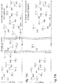
- FIG 1 an exemplary communication system is shown in which the data transmitter and the data receiver can be used.
- FIG. 1 shows in detail 1 a schematic view of a communication system with at least one data transmitter 100_1 and at least one data receiver 102_1.
- the communication system can optionally also include a second data transmitter 100_2, in which case the data transmitter 100_1 can be referred to as the first data transmitter 100_1.
- the communication system can optionally include a second data receiver 102_2, in which case the data receiver 102_1 can be referred to as the first data receiver 102_1.
- the first data transmitter 100_1 and the second data transmitter 100_2 can be the same data transmitter.
- the first data receiver 102_1 and the second data receiver 102_2 can be the same data receivers.
- the first data transmitter 100_1 can, for example, send a first data packet 104 to the first data receiver 102_1 and a second data packet 106 to the second data receiver.
- the first data receiver 102_1 receives the first data packet 104
- the second data receiver 102_2 receives the second data packet 106.
- the first data transmitter 100_1 can also send the first data packet 104 to the first data receiver 102_1 and the second data packet 106 to the second data receiver 102_2.
- the first data receiver 102_1 receives the first data packet 104
- the second data receiver 102_2 receives the second data packet 106.
- the second data transmitter 100_2 can send at least one of the two data packets 104 and 106 to the respective data receiver 102_1 and 102_2 instead of the first data transmitter 100_1. Accordingly, one of the two data receivers 102_1 and 102_2 can also receive both data packets 104 and 106, which can be sent by one or both data transmitters 100_1 and 100_2.
- the second data transmitter 100_2 can be another data transmitter 100_2, which sends another data packet 108.
- the other data transmitter 100_2 does not have to be part of the communication system.
- an interferer 110 can be present next to the communication system, which interferes with the transmissions of the communication system.
- the data transmitters can be both base stations and nodes (sensor nodes).
- the system can be used to transmit data from a base station, e.g., control data for adjusting individual parameters of an actuator or sensor, to a single or a large number of simple nodes.
- the radio transmission band used is usually not reserved exclusively for this transmission, but is shared with many other systems, which makes reliable transmission of the information more difficult.
- suitable bands are subject to regulation that limits the allowed transmission time over a given period.
- the telegram splitting method can be used both for the transmission of data from the node to the base station and to the Transmission of data from the base station to the node are used.
- the energy consumption of the nodes must be kept low, since they may not have a constant power supply, but instead operate so-called energy harvesting, i.e. draw energy from the environment (temperature differences, sunlight, electromagnetic waves, etc.), or a Have a battery that cannot provide power for the transmitter or receiver for a long enough time.
- the data transmitter 100_1 comprises a device 112 for generating transmission data packets, which is designed to divide a first data packet 104 into at least three transmission data packets 104_1 to 104_n (n can be a natural number greater than or equal to three), each of the at least three transmission data packets 104_1 to 104_n is shorter than the first data packet 104, wherein the device 112 for generating data packets is designed to channel-code the at least three transmission data packets 104_1 to 104_n in such a way that only a proportion of the transmission data packets 104_1 to 104_n (e.g.
- the data transmitter 100_1 also includes a device 114 for sending data packets, which is designed to send the at least three transmission data packets 104_1 to 104_n in a frequency channel via a communication channel with a time interval 116.
- the data transmitter 100_1 also includes a device 118 for monitoring the frequency channel, which is designed to detect interference 120 from the interferer 110 or a transmission 122 from another data transmitter 100_2 in the frequency channel.
- Device 114 for sending data packets is designed not to send a transmission data packet of the at least three transmission data packets 104_1 to 104_n waiting to be sent, only partially or later via the communication channel if there is a fault 120 or a transmission at the time the transmission data packet is sent 122 is recognized by another data transmitter 100_2 by the device 118 for monitoring the frequency channel.
- the data transmitter 100_1 can thus, upon detection of a fault 120 or a transmission 122 from another data transmitter 100_2, not transmit the transmission data packet pending transmission, only partially or later via the communication channel. Due to the channel coding used with which the Transmission data packets 104_1 to 104_n are channel-coded, it is even possible not to transmit one (or more) of the transmission data packets, only partially or later, without this resulting in data loss or loss of information, since only a portion, i.e. not all, of the transmission data packets for decoding of the first data packet 104 are required.
- a fault 120 or transmission 122 of another data transmitter 100_2 can occur shortly before the planned transmission of the third transmission data packet 104_3 and can be detected by the device 118 for monitoring the frequency channel, whereupon the device 114 for sending data packets transmits the third transmission data packet 104_3 not, only partially or later via the communication channel.
- the device 118 for monitoring the frequency channel can be designed to carry out a power detection in the frequency channel in order to identify the interference 120 or the transmission 122 of the other data transmitter 100_2 in the frequency channel.
- the device 118 for monitoring the frequency channel can be designed to detect the interference 120 or the transmission 120 of the other data transmitter 100_2 in the frequency channel based on a previous interference or previous transmission of another data transmitter and/or based on an interference or to predict transmission of another data transmitter in a frequency channel adjacent to the frequency channel.
- the device 114 for sending data packets can also be designed to adapt the time interval 116 between the transmission data packets 104_1 to 104_n depending on the detected fault 120 or transmission 122 of the other data transmitter 100_2.
- FIG. 3a shows in detail Figure 3a in a diagram an occupancy of the communication channel (transmission medium) with the pending (planned) transmission data packets 104_1 to 104_n to be transmitted and a fault 120 or other transmission 122, during Figure 3b in a diagram an occupancy of the communication channel with the transmission data packets 104_1 to 104_n that were actually transmitted, taking into account the interference 120 or other transmission 122 shows.
- the ordinate describes in Figures 3a and 3b in each case the frequency and the abscissa in each case the time.
- the data transmitter 100_1 (or the device 114 for sending data packets) can be designed to transmit a third transmission data packet 104_3 and a sixth transmission data packet 104_6 of the at least three transmission data packets 104_1 to 104_n due to the detected fault 120 or other transmission 122 not to send.
- the device 114 for sending data packets can be designed to distribute the transmission packets over a plurality of (at least two) frequency channels (or transmission frequencies).
- the data transmitter 100_1 can therefore use the telegram splitting method with monitoring of the frequency channel (listen-before-talk) in the transmission path.
- Figures 2 to 3b thus relate to a transmission system with telegram splitting, in which individual subpackets (transmission data packets) 104_1 to 104_n are not transmitted or only partially transmitted if activity is detected in the channel on the frequency range in which the subpacket is to be transmitted. Activity can take place eg by means of a power detection in the destination band of the subpacket. In addition, it is possible to predict the activity of the channel using existing observations from the past or the current adjacent channel activity.
- the error protection channel coding
- the data transmitter 100_1 comprises a device 112 for generating transmission data packets, which is designed to divide a first data packet 104 intended for the first data receiver 102_1 into at least two transmission data packets 104_1 to 104_n (n can be a natural number greater than or equal to two), each of the transmission data packets 104_1 to 104_n intended for the first data receiver 102_1 is shorter than the first data packet 104.
- the data transmitter 100_1 also includes a device 114 for transmitting data packets, which is designed to include the at least two transmission data packets 104_1 to 104_n intended for the first data receiver 102_1 a time interval 116 over a communication channel.
- the device 114 for sending data packets is designed to at least one more To send transmission data packet 124 to the first data receiver 102_1 or the second data receiver 102_2 in the time interval 116 between the at least two transmission data packets 104_1 to 104_n intended for the first data receiver 102_1.
- the data transmitter 100_1 can thus use the time interval (e.g. gap, pause) 116 between two transmission data packets 104_1 to 104_n or between the transmission of two transmission data packets 104_1 to 104_n in order to transmit (at least) one further transmission data packet 124, as a result of which channel occupancy or .Channel utilization can be improved.
- time interval e.g. gap, pause
- the further transmission data packet 124 can be any data packet which can be transmitted using any transmission method.
- the further transmission data packet 124 may be one of at least two transmission data packets, by means of which the data transmitter 100_1 sends the second data packet 106 divided over the communication channel to the first data receiver 102_1 or the second data receiver 102_2.
- device 112 for generating transmission data packets can be designed to divide the second data packet 106 intended for the second data receiver 102_2 into at least two transmission data packets 106_1 to 106_m (m can be a natural number greater than or equal to two), each of the at least two transmission data packets 106_1 to 106_m for the second data receiver 102_2 is shorter than the second data packet 106.
- the device 114 for sending data packets can be designed to send the at least two transmission data packets 106_1 to 106_m with a time interval over the communication channel. In this case, one of the at least two transmission data packets 106_1 to 106_m of the second data packet 106 can be the further transmission data packet.
- device 114 for sending data packets can be designed to alternately transmit the at least two transmission data packets 104_1 to 104_n intended for the first data receiver 102_1 and the at least two transmission data packets 106_1 to 106_m intended for the second data receiver 102_2 in the time interval between the to send the respective other data receiver specific transmission data packets.
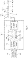
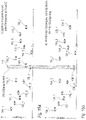
- figure 5 shows a schematic view of a system 128 with the in 4 shown data transmitter 100_1 and multiple data receivers 102_1 to 102_4, according to an embodiment. shows in detail figure 5 the first data receiver 102_1 and the second data receiver 102_2.
- the system 128 may further (optionally) include a third data receiver 102_3 and a fourth data receiver 102_4.
- the data transmitter 100_1 and the fourth data receiver 102_4 can be base stations, while the first data receiver 102_1, second data receiver 102_2 and third data receiver 102_3 can be nodes (sensor nodes).
- figure 5 accordingly shows the distribution of data packets (or telegrams) from a subscriber (data sender) 100_1 to other subscribers (data receivers) 102_1 to 102_4.
- FIG. 6 shows in a diagram the occupancy of the communication channel (transmission medium) for the in figure 5 system 128 shown, according to one embodiment. It describes in 6 the ordinate the frequency and the abscissa the time.
- device 114 for sending data packets can be designed to send the at least two send data packets 104_1 to 104_n intended for first data receiver 102_1 (in 6 also denoted by "A") with a time interval over the communication channel.
- Device 114 for sending data packets can be designed to transmit further send data packet 124 (in 6 denoted by "B") to the second data receiver 102_2 in the time interval 116 between the at least two transmission data packets 104_1 to 104_n intended for the first data receiver 102_1.
- the further transmission data packet 124 can be sent to the second data receiver 102_2 using a different transmission method (ie not using the telegram splitting method).
- Device 112 for generating data packets can also be designed to split a third data packet intended for third data receiver 122_3 into at least two transmission data packets 130_1 to 130_m (in 6 also denoted by "C") to split (m can be a natural number greater than or equal to two), each of the transmission data packets 130_1 to 130_m intended for the third data receiver 102_3 being shorter than the third data packet.
- the device 114 for sending data packets can be designed to send the at least two transmission data packets 130_1 to 130_m intended for the third data receiver 102_3 over the communication channel with a time interval.
- the device 112 for generating data packets can be designed to split a fourth data packet intended for the fourth data receiver 102_4 into at least two transmission data packets 132_1 to 132_i (in 6 also denoted by "2") (i can be a natural number greater than or equal to two), each of the transmission data packets 132_1 to 132_i intended for the fourth data receiver 102_4 being shorter than the fourth data packet.
- the device 114 for sending data packets can be designed to send the at least two transmission data packets 132_1 to 132_i intended for the fourth data receiver 102_4 over the communication channel with a time interval.
- the at least two transmission data packets 104_1 to 104_n intended for the first data receiver 102_1, the at least two transmission data packets 130_1 to 126_m intended for the third data receiver 102_3 and the at least two transmission data packets 132_1 to 132_i intended for the fourth data receiver 102_4 can alternately in the chronological Distances between the transmission data packets intended for the respective other data receiver are sent.
- the data transmitter 100_1 can therefore use the telegram splitting method for communication with the first, third and fourth data receivers 102_1, 102_3 and 102_4, and another transmission method for communication with the second data receiver 102_2.
- the telegram splitting method could also be used for the communication with the second data receiver 102_2.
- the device 108 for sending data packets can be designed to distribute the transmission packets over a plurality of (at least two) frequency channels (or transmission frequencies).
- a subscriber (data transmitter) 100_1 can transmit to a number of other subscribers (data receivers) 102_1 to 102_4 with a time overlap. This is possible due to the comparatively long pauses in telegram splitting.
- the sends Subscriber (data sender) 100_1 in a pause between two subpackets (transmission data packets) a further transmission to another subscriber (data receiver) or at least one further transmission to the same subscriber.
- This transmission can also take place by means of telegram splitting, but also with any other transmission technology. If telegram splitting is used, different jump patterns can be used, or the same one, but at different times. It is also possible, but not necessary, to also send the time-delayed hopping pattern with a frequency offset.
- the transmission of the entire telegram (data packet) takes a comparatively long time due to the time jump pattern, since many pauses are made to increase the interference immunity. During the pauses, it is possible to send the transmission to another participant as well, as shown in the example of the transmission of several telegrams that overlap in time 6 is shown. In detail it is possible 6 an occupancy of the spectrum for the simultaneous transmission of four messages (data packets) A, B, C and 2.
- the telegram splitting method can be used for the first, third and fourth message A, C and 2.
- For the first and third messages A and C the same but time and frequency shifted subpacket pattern can be used.
- For the fourth message 2 a different subpacket pattern can be used.
- a different transmission technique can be used for the second message B.
- Telegram splitting in the receive path simultaneous receipt of several telegrams
- the data receiver 102_1 includes a device 134 for receiving data packets, which is designed to receive at least two transmission data packets 104_1 to 104_n (n can be a natural number greater than or equal to two) from a first data transmitter 100_1, with a time interval 116 over a Communication channel are sent and each contain a part of a first data packet 104, wherein the device 134 for receiving data packets is designed to combine the at least two transmission data packets 104_1 to 104_n in order to receive the first data packet 104.
- the device 134 for receiving data packets is designed to receive at least one further data packet 124 from the first data transmitter 100_1 or the second data transmitter 100_2 in the time interval 116 between the at least two transmission data packets 104_1 to 104_n.
- the further transmission data packet 124 can be transmitted by the first data transmitter 100_1 or the second data transmitter 100_2 using any transmission method (i.e. not using the telegram splitting method).
- the further transmission data packet 124 may be one of at least two transmission data packets, by means of which the first data transmitter 100_1 or the second data transmitter 100_2 sends the second data packet 106 divided over the communication channel to the data receiver 102_1.
- the device 134 for receiving data packets can be configured to receive at least two transmission data packets 106_1 to 106_m from the second data transmitter 100_2 (m can be a natural number greater than or equal to two), which are transmitted over a communication channel at a time interval and each contain part of the second data packet 106, the device 134 for receiving data packets being designed to combine the at least two transmission data packets 106_1 to 106_m from the second data transmitter 100_2 in order to receive the second data packet 106.
- one of the at least two transmission data packets 106_1 to 106_m can be the further transmission data packet 124.
- device 134 for receiving data packets can be designed to transmit the at least two transmission data packets 104_1 to 104_n from the first data transmitter 100_1 and the at least two transmission data packets 106_1 to 106_m from the second data transmitter 100_2 alternately in the time interval between the transmission data packets received from the other data transmitter.
- a participant eg data receiver 102_1 can thus receive from several other participants (eg data transmitters 100_1 to 100_2) with a time overlap. This is possible due to the comparatively long pauses in telegram splitting.
- the participant receives a further transmission from another participant or at least one further message from the same participant.
- This transmission can also take place by means of telegram splitting, but also with any other transmission technology. If telegram splitting is used, different or the same subpacket pattern can be used, but at different times. It is also possible, but not necessary, to also send the time-shifted subpacket patterns with a frequency offset.
- the transmission of the entire telegram (eg first data packet 104 or second data packet 106) takes a comparatively long time due to the hopping pattern/time hopping pattern, since many pauses are made in order to increase the interference immunity.
- the breaks it is possible to also receive the transmission from another participant, as shown below using the in 8 shown example of a system with several temporally overlapping telegrams is explained.
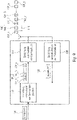
- FIG. 8 shows a schematic view of a system 128 with the in 7 shown data receiver 102_1 and multiple data transmitters 100_1 to 100_4, according to an embodiment.
- four data transmitters 100_1 to 100_4 can be identified, with the data receiver 102_1 receiving a first data packet "A" from a first data transmitter 100_1, a second data packet “B” from a second data transmitter 100_2, a third data packet “C” from the third data transmitter 100_3, and from the fourth data transmitter 100_4 receives a fourth data packet "2".
- the data receiver 102_1 can be a base station.
- the first data transmitter 100_1, second data transmitter 100_2 and third data transmitter 100_3 can be nodes (sensor nodes), while the fourth data transmitter 100_4 can be a base station.
- the disturbed data can in many cases be corrected with the help of error correction.
- SIC Successive Interference Cancellation
- the receiving station has several receiving antennas, it is also possible to use beamforming (beam shaping) or beamforming algorithms.
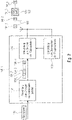
- FIG. 9 shows a schematic view of the in 4 shown data transmitter 100_1 with an additional device 138 for receiving data packets, according to an embodiment.
- the following description also applies in a corresponding manner to the in 2 shown data transmitter 100_1.
- the transmission path of the data transmitter 100_1 reference is therefore made to the statements above.
- the data transmitter 100_1 can be a data transceiver, which also has a device 138 for receiving data packets.
- the means 138 for receiving Data packets can be designed to receive a transmission data packet 140 from another data transmitter 100_2 in the time interval 116 between the transmission data packets 104_1 to 104_n intended for the first data receiver 102_1.
- the transmission data packet 140 from the other data transmitter 100_2 can be transmitted using any transmission method.
- the transmission data packet 140 can also be one of at least two transmission data packets, by means of which the other data transmitter 100_2 transmits another data packet 108 divided to the data transceiver 100_1.
- the device 138 for receiving data packets can be designed to receive at least one of at least two transmission data packets 108_1 to 108_b (where b is a natural number greater than or equal to two) in the time interval between the transmission data packets 104_1 to 104_n intended for the first data receiver 102_1 which are sent by the other data transmitter 100_2, the at least two transmission data packets 108_1 to 108_b being sent by the other data transmitter 100_2 over the communication channel at a time interval and each containing a part of the other data packet 108, the device 138 for receiving of data packets is designed to combine the at least two transmission data packets 108_1 to 108_b in order to obtain the other data packet 108.
- one of the at least two transmission data packets 108_1 to 108_b from the other data transmitter 100_2 can be the transmission data packet 140 from the other data transmitter 100_2.
- a participant e.g. transceiver 100_1
- the receiving station it is also possible for the receiving station to support full-duplex operation and thus be able to transmit and receive on the same frequency at the same time.
- This additional transmission can also take place by means of telegram splitting, but also with any other transmission technique.
- telegram splitting is used, different or the same subpacket pattern can be used, but at different times. It's also possible, but not necessary to also send the time-delayed subpacket pattern with a frequency offset.
- the data transceiver 100_1 can receive a first data packet "A" from the second data transmitter 100_2, send a second data packet "B” to the second data receiver 102_2, send a third data packet "C” to the third data receiver 102_3 and send a fourth data packet "2" from the third data transmitter 100 received.
- the transceiver 100_1 can be a base station.
- the second data transmitter 100_2, the second data receiver 102_2, the third data receiver 102_3 can be sensor nodes, while the third data transmitter 100_3 can be a base station.
- base station 1 (100_1) can send to sensor node B (102_2) and sensor node C (102_3) while simultaneously receiving messages from base station 2 (100_3) and sensor node A (100_2).
- the base station 100_1 would therefore like to transmit to two sensor nodes 102_2 and 102_3 while receiving a message from a further sensor node 100_2 and a base station 100_3.
- the transmission of the entire telegram takes a comparatively long time due to the jump pattern / time jump pattern, since many pauses are made to increase the interference immunity. In the pauses, it is possible to carry out another transmission, see the example of the transmission of several telegrams that overlap in time 6 .
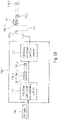
- 11 12 shows a schematic view of a system 128 with two transceivers 100_1 and 100_2 according to an embodiment.
- 11 an example of duplex operation between two participants can be found.
- a participant transmits and receives with an overlap in time with the same other participant. This transmission is not limited to telegram splitting or one message per direction.
- the first transceiver 100_1 can be a base station, while the second transceiver 100_2 can be a sensor node.
- the base station 100_1 can send two messages (data packets) to the sensor node 100_2, while the sensor node sends one message (data packet) to the base station 100_1.
- FIG. 12 shows in a diagram the occupancy of the communication channel (transmission medium) for the in 11 system 128 shown, according to one embodiment.
- the ordinate describes frequency while the abscissa describes time.
- the first transceiver 100_1 can be designed to send the first data packet 104 divided into the at least two transmission data packets 104_1 to 104_n to the second transceiver 100_2 (telegram splitting). Furthermore, the first transceiver 100_1 can be designed to send the further transmission data packet 124 to the second transceiver 100_2 in the time interval between the at least two transmission data packets 104_2 and 104_3 (different transmission method).
- the second transceiver 100_2 can be designed to send the second data packet 106 divided into the at least two transmission data packets 106_1 to 106_m to the first data transceiver 100_1 (telegram splitting).
- the transmission data packets from the first transceiver and the transmission data packets from the second transceiver can be transmitted in the time interval between the respective other transmission data packets.
- Telegram distribution in the transmission path with transmission to several participants overlapping transmission data packets being omitted
- the data transmitter 100_1 includes a Device 112 for generating transmission data packets, which is designed to divide the first data packet 104 into at least three transmission data packets 104_1 to 104_n (n can be a natural number greater than or equal to three), each of the at least three transmission data packets 104_1 to 104_n being shorter than the first Data packet 104, wherein the device 112 for generating transmission data packets is designed to channel-code the at least three transmission data packets 104_1 to 104_n in such a way that only a proportion of the transmission data packets (e.g.
- the data transmitter also includes a device 114 for sending data packets, which is designed to send the at least three transmission data packets 104_1 to 104_n over a communication channel with a time interval 116 .
- Device 114 for sending data packets can be designed not to send a transmission data packet of the at least three transmission data packets that is pending to be sent, only partially or later if another transmission data packet 124 is pending transmission at the time the one transmission data packet is being transmitted.
- the data transmitter can thus, if, for example, at the time of the transmission of the one transmission data packet, another transmission data packet is due to be sent, the transmission data packet of the at least three transmission data packets that is due to be sent cannot be sent, only partially or later via the communication channel. Due to the channel coding used, with which the transmission data packets are channel-coded, it is even possible not to transmit one (or more) of the transmission data packets or to only partially transmit them, without this resulting in a loss of data or information, since only a portion, i.e. not all, of the transmission data packets are required for decoding the first data packet.
- the device 114 for sending data packets cannot send the second transmission data packet, only partially or later.
- the device 114 for sending data packets can be designed to send the further transmission data packet 124 via the communication channel.
- the data sender 100_1 can send the further transmission data packet 124 itself.
- the further transmission data packet 124 can be transmitted using any transmission method.
- the further transmission data packet 124 is one of at least three transmission data packets 106_1 to 106_m, by means of which the second data packet 106 is transmitted divided.
- the at least three transmission data packets 104_1 to 104_n can be intended for a first data receiver 102_1.
- Device 112 for generating transmit data packets can be designed to split a second data packet 106 intended for a second data receiver 102_2 into at least three transmit data packets 106_1 to 106_m (m can be a natural number greater than or equal to three), each of the data packets intended for the second data receiver 102_2 specific transmission data packets 106_1 to 106_m is shorter than the second data packet 106, wherein the device 112 for generating data packets can be designed to channel-code the at least three transmission data packets 106_1 to 106_m intended for the second data receiver 102_2 in such a way that only a proportion of the transmission data packets for Decoding of the second data packet 106 is required.
- the device 114 for sending data packets can be designed to send the at least three transmission data packets 106_1 to 106_m intended for the second data receiver 102_2 over the communication channel at a time interval.
- one of the at least three transmission data packets intended for the second data receiver 102_2 can be the further transmission data packet 124.
- the further transmission data packet 124 can also be sent by another data transmitter 100_2.
- the data sender 100_1 can know the time at which the further transmission data packet 124 was sent by the other data sender 100_2.
- FIG. 14a shows in a diagram an occupancy of the communication channel (transmission medium) with the pending (planned) transmission data packets to be transmitted during
- Figure 14b shows in a diagram an occupancy of the communication channel with the transmission data packets actually transmitted.
- the ordinate describes the frequency in each case, while the abscissa describes the time in each case.
- the first data packet 104 can be divided into the transmission data packets 104_1 to 104_n
- the second data packet 106 can be divided into the transmission data packets 106_1 to 106_m
- the third data packet can be divided into the transmission data packets 130_1 to 130_i, each with a time interval in the time intervals between be sent with the respective other transmission data packets.
- the planned transmission of the transmission data packets would lead to two overlapping areas 142 and 144.
- a subscriber can therefore transmit to several other subscribers with an overlap in time. There is a high probability that the time jump patterns can overlap for some transmission data packets.
- the sender can know which subpackets (transmission data packets) will overlap (see 14a ).
- the overlapping subpackets cannot be sent out (see Figure 14b ) because the recipients can detect the missing subpacket and can process this information - i.e. evaluate the subpacket as missing information.
- This procedure can be better than sending one of the subpackages to a specific recipient, since the other at least one participant who is also expecting a subpackage at this point may not be able to determine that the subpackage was not intended for them and is therefore a subpackage received which contained information that was useless for decoding its telegram. Incorrect information is worse for error protection decoding than no information.
- the device 114 for sending data packets can be designed to only not send the pending transmission data packet of the at least three transmission data packets 104_1 to 104_n, only partially or later if the further transmission data packet also meets a transmission criterion.
- the transmission criterion can indicate that the further transmission data packet 124 has a higher transmission priority than the transmission data packet of the at least three transmission data packets 104_1 to 104_n that is awaiting transmission.
- the transmission criterion can indicate that the transmission data packet 104_1 to 104_n pending transmission and the further transmission data packet 124 are transmitted in the same frequency channel.
- both subpackets can usually be transmitted and omission is not necessary. Also if signals only overlap in time and not in the frequency range, it may still be necessary to send only one signal, e.g. if the transmitter can only transmit one subpacket at a time for technical reasons, even if they do not overlap in the frequency range.
- a decision as to which subpackets are omitted can result from various parameters. For example, from the channel attenuation to the receiver or from the number of subpackets that have already been omitted.
- the device 114 for sending data packets can be designed to only not send the pending transmission data packet of the at least three transmission data packets 104_1 to 104_n, only partially or later if the further transmission data packet also meets a transmission criterion.
- the transmission criterion can specify, for example, that the transmission of the further transmission data packet 124 requires a decoding of the first data packet 104 by a data receiver based on the other transmission data packets of the at least three transmission data packets 104_1 to 104_n with a probability of at least 90% (or 70%, or 80% or 95%) is still possible.
- a channel quality for example, can be taken into account for determining the probability.
- a number of previously untransmitted transmission data packets of the at least three transmission data packets 104_1 to 104_n can be taken into account.
- Figure 15a shows in a diagram an occupancy of the communication channel (transmission medium) with the pending (planned) transmission data packets to be transmitted during
- Figure 15b shows in a diagram an occupancy of the communication channel with the transmission data packets actually transmitted.
- the ordinate describes the frequency in each case, while the abscissa describes the time in each case.
- the first data packet 104 can be divided into the transmission data packets 104_1 to 104_n and the second data packet 106 can be divided into the transmission data packets 106_1 to 106_m each with a time interval in the time intervals between the other transmission data packets.
- the planned transmission of the transmission data packets would lead to an overlapping area 142 in which the transmission data packets 104_4 and 106_4 overlap.
- the transmission data packet 104_4 is not transmitted.
- a subscriber can therefore transmit to several other subscribers with an overlap in time. There is a high probability that the time hopping patterns may overlap in time for some subpackets. In the case of overlapping sub-packets, a sub-packet is only sent if the base station considers it important for one participant and not very disruptive for the other participant.
- the disturbance can be evaluated, for example, based on the channel quality between the participants in the past. In the event that the channel between two participants (e.g. A and C) was very good, the probability of one participant (e.g. C) being disturbed by a transmission to the other participant (e.g. B) is very low. If the channel between two participants (e.g. A and B) has always been critical, an additional disruption caused by the sending of the subpacket to one participant (e.g. C) in the event of an overlap would increase the reception quality of the message to the other participant (e.g. B) even further be reduced. Another criterion for the evaluation can also be the number of subpackets of a telegram that have already been omitted.
- a subpacket with a low interference potential can still be sent out in the event of an overlap.
- transmissions to two subscribers e.g. C and B
- the subpacket for one participant e.g. C
- the subpacket for the other participant e.g. B
- Telegram distribution in the transmission path with transmission data packets being omitted depending on external conditions
- the device for sending data packets can instead (or further) be designed to transmit pending Transmission data packet of at least three transmission data packets depending on external conditions not to send only partially or later.
- the data transmitter (e.g. base station) 100_1 can therefore not send individual transmission data packets, only partially or later, if these should not be sent due to external circumstances (e.g. regulatory circumstances, such as an overall duty cycle, or by reporting from a primary network (e.g. UMTS)). .
- external circumstances e.g. regulatory circumstances, such as an overall duty cycle, or by reporting from a primary network (e.g. UMTS)).
- Telegram splitting in the send or receive path with a hop pattern adapted to the channel
- the device 114 for sending data packets can be designed to adapt the time interval between the transmission data packets, the frequency channel or frequency channels to which the transmission data packets are distributed or the non-transmission of a transmission data packet depending on the quality or occupancy of the communication channel.
- the device 114 for sending data packets can be designed to adapt the hopping pattern used to a quality or occupancy of the communication channel.
- the data transmitter (or data transceiver) 100_1 can be designed to transmit the transmission time of at least one of the transmission data packets or at least a time interval between two of the transmission data packets using a further transmission data packet.
- the data transmitter 100_1 can be designed to communicate its own hopping pattern to other data transmitters, e.g. using a corresponding transmission data packet with information about the hopping pattern.
- the data transmitter prefferably be designed, using a further transmission data packet, to specify to another data transmitter a transmission time at which the other data transmitter transmits a transmission data packet, or a time interval between two transmission data packets transmitted by the other data transmitter.
- a data sender e.g. a base station
- the selection of the hopping pattern to be used for sending is freely selectable.
- the hopping pattern can be chosen to provide better performance than the expected transmission channel for the transmission one chosen at random.
- the participant can use information he has collected himself or received externally about the current channel and from the past (e.g. radio channel situation of the previous seconds, general channel situation in this area, situation at the same time last week, etc.).
- channel estimation and pattern selection can be left to one participant alone.
- Telegram splitting for simultaneous sending and receiving, with sending data packets (subpackets) to be sent that collide with required sending data packets (receiving subpackets) being omitted
- the transmission of a subpacket from one participant can overlap with the receipt of a subpacket from another participant.
- the receiver would be blind to the receipt of the subpacket while sending the other subpacket.
- a decision to drop can be made, for example, based on information such as the channel attenuation to the receiver and the number of subpackets that have already been dropped.
- the uplink transmission can be classified as important, e.g. higher-priority hopping pattern.
- the base station can now interrupt the transmission of the downlink message at the corresponding reception times of the uplink of the sensor node and thus ensure the receipt of the sensor node telegram without significantly compromising its own downlink message.
- Telegram distribution in the send or receive path prioritized telegrams can be preferred when sending and receiving
- a participant can send or receive a telegram with high priority. All overlapping subpackets of other telegrams, regardless of whether they are in the send or receive direction, can be ignored in favor of this prioritized telegram.
- Transmissions that overlap with the receipt of a sub-packet of the prioritized telegram can be suspended. Transmission or receipt of a subpacket of a non-prioritized telegram can always be suspended in the event of an overlap and the subpacket of the prioritized telegram can be sent instead.
- Telegram distribution in the transmission path transmission power of the telegram distribution procedure is adapted to the participants
- the device for receiving data packets of data transceiver 100_1 can also be designed to receive a data packet from the first data receiver and to determine a reception power, wherein data transceiver 100_1 can be designed to transmit a transmission power with which the transmission data packets are sent to the first data receiver are adjusted depending on the determined reception power.
- a participant e.g. A
- the transmission power of your own telegram to the other participants can now be adjusted.
- the participants can better distinguish their telegrams from the other telegrams sent based on the level be able. This can improve (or even maximize) identifiability.
- a base station can transmit in a time-overlapping manner to a plurality of sensor nodes, eg to a first sensor node (A) and a second sensor node (B), with transmissions from the first sensor node (A) having a low and transmissions from the second sensor node (B) arrive with high field strength.
- the base station can then send sub-packets to the first sensor node (A) with high power and sub-packets to the second sensor node (B) with low power.
- subpackets for the first sensor node (A) can be sent out.
- the second sensor node (B) can detect that a subpacket was not intended for the second sensor node (B) if the field strength is higher than other subpackets.
- BC broadcast
- MC multicast
- the method 200 comprises a step 202 of generating at least two transmission data packets by dividing a first data packet intended for a first data receiver into the at least two transmission data packets, each of the transmission data packets intended for the first data receiver being shorter than the first data packet; a step 204 of sending the at least two transmission data packets intended for the first data receiver with a time interval via a communication channel; and a step 206 of sending a further transmission data packet to the first data receiver or a second data receiver in the time interval between the at least two transmission data packets intended for the first data receiver.
- the method 210 comprises a step 212 of generating at least three transmission data packets by dividing a first data packet intended for a first data receiver into the at least three transmission data packets, each of the at least three transmission data packets being shorter than the first data packet, with the generation of the at least three transmission data packets the at least three transmission data packets are channel-coded in such a way that only a portion of the transmission data packets is required to decode the first data packet; a step 214 of sending the at least three transmission data packets in a frequency channel over a communication channel with a time interval; and a step 216 of monitoring the frequency channel to detect interference or transmission of another data transmitter in the frequency channel; wherein when the at least three transmission data packets are being sent, a transmission data packet of the at least three transmission data packets that is due to be sent is not sent, is sent only partially or later via the communication channel if at the time the data packet is sent there is
- the method 220 comprises a step 222 of generating at least three transmission data packets by dividing a first data packet intended for a first data receiver into the at least three transmission data packets, each of the at least three transmission data packets being shorter than the first data packet, with the generation of the at least three transmission data packets the at least three transmission data packets are channel-coded in such a way that only a portion of the transmission data packets is required to decode the first data packet; and a step 224 of transmitting the at least three transmission data packets in a frequency channel over a communication channel with a time interval; wherein when the at least three transmission data packets are being sent, a transmission data packet of the at least three transmission data packets that is due to be sent is not transmitted, is only partially transmitted or is transmitted later if another transmission data packet is due to be transmitted at the time the one transmission data packet is transmitted.
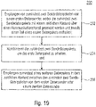
- FIG. 2 shows a flowchart of a method 230 for receiving data packets according to an embodiment.
- the method 230 comprises a step 232 of receiving at least two transmission data packets from a first data transmitter, wherein the at least two transmission data packets are transmitted over a communication channel with a time interval and each contain a part of a first data packet; a step 234 of combining the at least two transmission data packets to obtain the first data packet; and a step 236 of receiving at least one further data packet in the time interval between the at least two transmission data packets from the first data transmitter or a second data transmitter.
- a data transmitter 100_1 has the following features: a device 112 for generating transmission data packets, which is designed to divide a first data packet 104 intended for a first data receiver 102_1 into at least two transmission data packets 104_1-104_n, with each of the data packets for the first data receiver 102_1 specific transmission data packets 104_1-104_n is shorter than the first data packet 104; a device 114 for sending data packets, which is designed to send the at least two transmission data packets 104_1-104_n intended for the first data receiver 102_1 with a time interval 116 via a communication channel; wherein the device 114 for sending data packets is designed to send at least one further transmission data packet 124 to the first data receiver 102_1 or a second data receiver 102_2 in the time interval 116 between the at least two transmission data packets 104_1-104_n intended for the first data receiver 102_1.
- the device 112 for generating transmission data packets is designed to divide a second data packet 106 intended for the second data receiver 102_2 into at least two transmission data packets 106_1-106_n, with each of the transmission data packets intended for the second data receiver 102_2 106_1-106_m is shorter than the second data packet 106; wherein the device 114 for sending data packets is designed to send the at least two transmission data packets 106_1-106_m intended for the second data receiver 102_2 with a time interval via the communication channel; and wherein one of the at least two transmission data packets 106_1-106_m intended for the second data receiver 102_2 is the further transmission data packet 124.
- the device 114 for sending data packets is designed to alternately send the at least two transmission data packets 104_1-104_n intended for the first data receiver 100_1 and the at least two transmission data packets 106_1-106_m intended for the second data receiver 102_2 in the time interval between the transmission data packets intended for the respective other data receiver.
- the at least two transmission data packets 104_1-104_n are at least three transmission data packets 104_1-104_n
- the device 112 for generating transmission data packets being designed to channel code the at least three transmission data packets 104_1-104_n in this way that only a portion of the transmission data packets 104_1-104_n for decoding the first data packet 104 is required.
- a data transmitter 100_1 has the following features: a device 112 for generating transmission data packets, which is designed to transmit a first Divide data packet 104 into at least three transmission data packets 104_1-104_n, each of the at least three transmission data packets 104_1-104_n being shorter than the first data packet 104, wherein the device 112 for generating data packets is designed to channel code the at least three transmission data packets 104_1-104_n in such a way that only a portion of the transmission data packets 104_1-104_n is required for decoding the first data packet 104; a device 114 for sending data packets, which is designed to send the at least three transmission data packets 104_1-104_n in a frequency channel via a communication channel with a time interval 116; a device 118 for monitoring the frequency channel, which is designed to detect interference 120 or transmission 122 from another data transmitter 100_2 in the frequency channel; wherein the device 114 for sending data packets is
- the device 118 for monitoring the frequency channel is designed to perform power detection in the frequency channel in order to identify the interference 120 or the transmission 122 of the other data transmitter 100_2 in the frequency channel.
- the device 118 for monitoring the frequency channel is designed to detect the interference 120 or the transmission 122 of the other data transmitter 100_2 in the frequency channel based on a previous interference or previous transmission of another data transmitter to predict; or the device 118 for monitoring the frequency channel is designed to predict the interference 120 or the transmission 122 of the other data transmitter 100_2 in the frequency channel based on an interference or transmission of another data transmitter in a frequency channel adjacent to the frequency channel.
- the device 114 for sending data packets is designed to adapt the time interval 116 between the transmission data packets 104_1-104_n depending on the detected interference 120 or transmission 122 of the other data transmitter 100_2 .
- the device 114 for sending data packets is designed to send a further transmission data packet 124 to the first data receiver or a second data receiver in the time interval 116 between the at least two for the first data receiver 102_1 specific transmit data packets 104_1-104_n to send.
- the data transmitter 100_1 has the following features: a device 112 for generating transmission data packets, which is designed to divide a first data packet 104 into at least three transmission data packets 104_1-104_n, each of the at least three transmission data packets 104_1-104_n being shorter than the first data packet 104, wherein the device 112 for generating data packets is designed to channel code the at least three transmission data packets 104_1-104_n in such a way that only a portion of the transmission data packets 104_1-104_n is required to decode the first data packet 104; a device 114 for sending data packets, which is designed to send the at least three send data packets 104_1-104_n via a communication channel with a time interval 116; wherein the device 114 for sending data packets is designed not to send, only partially or later a send data packet of the at least three send data packets 104_1-104_n that is pending to be sent.
- the device 114 for sending data packets is designed not to send a pending send data packet of the at least three send data packets 104_1-104_n, only partially or later if at the time of sending the one Transmission data packet another transmission data packet 124 is pending for transmission.
- the device 114 for sending data packets is designed to send the further send data packet 124 via the communication channel.
- the at least three transmission data packets 104_1-104_n are intended for a first data receiver 102_1; wherein device 112 for generating transmission data packets is designed to divide a second data packet 106 intended for a second data receiver 102_2 into at least three transmission data packets 106_1-106_m, each of the transmission data packets 106_1-106_m intended for the second data receiver 102_2 being shorter than the second data packet 106; where the Device 112 for generating data packets is designed to channel code the at least three transmission data packets 106_1-106_m intended for the second data receiver 102_2 in such a way that only a portion of the transmission data packets is required to decode the second data packet 106; wherein the device 114 for sending data packets is designed to send the at least three transmission data packets 106_1-106_m intended for the second data receiver 102_2 over the communication channel
- the further transmission data packet 124 is transmitted by another data transmitter 100_2.
- the data sender knows the point in time at which the further transmission data packet 124 was sent by the other data sender 100_2.
- the device 114 for sending data packets is designed not to send a pending transmission data packet of the at least three transmission data packets 104_1-104_n, only partially or later, if at the time the transmission of the one transmission data packet, a further transmission data packet 124 is pending for transmission and the further transmission data packet 124 satisfies a transmission criterion.
- the transmission criterion indicates that the further transmission data packet has a higher transmission priority than the transmission data packet pending transmission of the at least three transmission data packets 104_1-104_n.
- the transmission criterion indicates that the transmission of the further transmission data packet 124 requires a decoding of the first data packet 104 by a data receiver 102_1,102_2 based on the other transmission data packets of the at least three transmission data packets 104_1-104_n with a probability of at least 90% is still possible.
- a channel quality is taken into account when determining the probability.
- a number of previously untransmitted transmission data packets of the at least three transmission data packets 104_1-104_n is taken into account when determining the probability.
- the transmission criterion indicates that the transmission data packet to be transmitted and the further transmission data packet 124 are transmitted in the same frequency channel.
- the data transmitter is a data transceiver, wherein the transmission criterion indicates that reception of the further transmission data packet 124 by the data transceiver 100_1 is required.
- the device 114 for sending data packets is designed to not, only partially or later to send a pending send data packet of the at least three send data packets 104_1-104_n depending on external circumstances send.
- the device 114 for sending data packets is designed to send a first of the transmission data packets intended for the first data receiver 102_1 in a first frequency channel, and to transmit a second of the transmission data packets intended for the second Send data receiver 102_2 specific transmission data packets in a second frequency channel.
- the device 114 for sending data packets is designed to distribute the send packets 104_1-104_n over at least two frequency channels.
- the data transmitter 100_1 is a data transceiver and also has the following feature: a device 138 for receiving data packets, which is designed to transmit at the time interval 116 to receive a transmission data packet 140 from another data transmitter 100_2 between the transmission data packets intended for the first data receiver 102_2.
- the device 138 for receiving data packets is designed to receive at least one of at least two transmission data packets 108_1-108_b in the time interval 116 between the transmission data packets 104_1-104_n intended for the first data receiver 102_1 are sent to the other data transmitter 100_2, the at least two transmission data packets 108_1-108_b being sent by the other data transmitter 100_2 over the communication channel at a time interval and each containing part of another data packet 108, the device 138 for receiving data packets is designed to combine the at least two transmission data packets 108_1-108_b in order to obtain the other data packet 108; wherein one of the at least two transmission data packets 108_1-108_b from the other data transmitter 100_2 is the transmission data packet 140 from the other data transmitter.
- the data transmitter 100_1 is designed to transmit the transmission time of at least one of the transmission data packets or at least a time interval between two of the transmission data packets using a further transmission data packet.
- the data transmitter 100_1 is designed to use a further transmission data packet to send another data transmitter a transmission time at which the other data transmitter transmits a transmission data packet, or a time interval between two of the other Specify data transmitter transmitted transmission data packets.
- the device 114 for sending data packets is designed to adjust the time interval between the send data packets or the non-sending of a send data packet depending on a quality or occupancy of the communication channel.
- the data transmitter is a data transceiver, further comprising the following Feature has: a device 138 for receiving data packets, which is designed to receive a data packet from the first data receiver 102_1 and to determine a reception power or a reception quality; wherein the data transmitter 100_1 is designed to adjust a transmission power with which the transmission data packets 104_1-104_n are sent to the first data receiver 102_1 depending on the determined reception power or the reception quality.
- the device 114 for sending data packets is designed to, if at the time of sending the one send data packet another send data packet 124 is due to be sent, to transmit the send data packet pending to be sent to send at least three transmission data packets 104_1-104_n partially in such a way that transmitted parts of one transmission data packet lead to a constructive superimposition with the further transmission data packet 124.
- the data receiver 102_1 has the following features: a device 134 for receiving data packets, which is designed to receive at least two transmission data packets 104_1-104_n from a first data transmitter 100_1, which are sent at a time interval 116 via a communication channel and each contain a part of a first data packet 104, the device 134 for receiving data packets being designed to combine the at least two transmission data packets 104_1-104_n in order to obtain the first data packet 104; wherein the device 134 for receiving data packets is designed to receive at least one further data packet 124 from the first data transmitter 100_1 or a second data transmitter 100_2 in the time interval 116 between the at least two transmission data packets 104_1-104_n.
- the device 138 for receiving data packets is designed to receive at least two transmission data packets 106_1-106_m from a second data transmitter 100_2, which are sent with a time interval via a communication channel and each part of a second data packet 106, the device 134 for receiving data packets being designed to combine the at least two transmission data packets 106_1-106_m in order to obtain the second data packet 106; at least one of the at least two transmission data packets 106_1-106_m from the second data transmitter 100_2 being the at least one further transmission data packet 124.
- the device 134 for receiving data packets is designed to transmit the at least two transmission data packets 104_1-104_n from the first data transmitter 100_1 and the at least two data packets 106_1-106_m from the second data transmitter 100_2 alternately in the temporal To receive distance between the transmission data packets from the other data transmitter.
- the at least two transmission data packets 104_1-104_n are at least three transmission data packets, the at least three transmission data packets 104_1-104_n being channel-coded in such a way that only a proportion of the at least three transmission data packets 104_1-104_n for decoding is required; wherein the device 138 for receiving data packets is designed to receive, combine and decode at least two of the at least three transmission data packets 104_1-104_n in order to obtain the first data packet 104.
- a system 128 has the following features: at least one data transmitter 100_1 according to one of the first to thirty-first aspects; and at least one data receiver 102_1 according to any one of the thirty-second to thirty-fifth aspects.
- a method has the following steps: generating at least two transmission data packets by dividing a first data packet intended for a first data receiver into the at least two transmission data packets, each of the transmission data packets intended for the first data receiver being shorter than the first data packet; sending the at least two transmission data packets intended for the first data receiver with a time interval via a communication channel; Sending a further transmission data packet to the first data receiver or a second data receiver in the time interval between the at least two transmission data packets intended for the first data receiver.
- a method has the following steps: Generating at least three transmission data packets by dividing a first data packet intended for a first data receiver into the at least three transmission data packets, each of the at least three transmission data packets being shorter than the first data packet, wherein when generating the at least three transmission data packets the at least three transmission data packets are channel-coded in such a way that only a proportion of the transmission data packets is required to decode the first data packet; sending the at least three transmission data packets in a frequency channel over a communication channel with a time interval; monitoring the frequency channel to detect interference or transmission of another data transmitter in the frequency channel; wherein when the at least three transmission data packets are being sent, a transmission data packet of the at least three transmission data packets that is due to be sent is not sent, is sent only partially or later via the communication channel if at the time the data packet is sent there is a fault or a transmission from another data transmitter from the device to Monitoring the frequency channel is detected.
- a method has the following steps: generating at least three transmission data packets by dividing a first data packet intended for a first data receiver into the at least three transmission data packets, each of the at least three transmission data packets being shorter than the first data packet, wherein when generating the at least three transmission data packets the at least three transmission data packets are channel-coded in such a way that only a portion of the transmission data packets is required to decode the first data packet; sending the at least three transmission data packets in a frequency channel over a communication channel with a time interval; wherein when the at least three transmission data packets are being sent, a transmission data packet of the at least three transmission data packets that is due to be sent is not transmitted, is only partially transmitted or is transmitted later if another transmission data packet is due to be transmitted at the time the one transmission data packet is transmitted.
- a method has the following steps: receiving at least two transmission data packets from a first data transmitter, the at least two transmission data packets being transmitted over a communication channel with a time interval and each containing part of a first data packet; combining the at least two transmit data packets to obtain the first data packet; and receiving at least one further data packet in the time interval between the at least two transmission data packets from the first data transmitter or a second data transmitter.
- a forty-second aspect features a computer program for performing a method according to any one of the thirty-eighth to forty-first aspects.
- aspects have been described in the context of a device, it is understood that these aspects also include a description of the corresponding Represent methods, so that a block or a component of a device is also to be understood as a corresponding method step or as a feature of a method step. Similarly, aspects described in connection with or as a method step also constitute a description of a corresponding block or detail or feature of a corresponding apparatus.
- Some or all of the method steps may be performed by hardware apparatus (or using a hardware apparatus), such as a microprocessor, a programmable computer, or an electronic circuit. In some embodiments, some or more of the major process steps can be performed by such an apparatus.
- embodiments of the invention may be implemented in hardware or in software. Implementation can be performed using a digital storage medium such as a floppy disk, DVD, Blu-ray Disc, CD, ROM, PROM, EPROM, EEPROM or FLASH memory, hard disk or other magnetic or optical memory, on which electronically readable control signals are stored, which can interact or interact with a programmable computer system in such a way that the respective method is carried out. Therefore, the digital storage medium can be computer-readable.
- a digital storage medium such as a floppy disk, DVD, Blu-ray Disc, CD, ROM, PROM, EPROM, EEPROM or FLASH memory, hard disk or other magnetic or optical memory, on which electronically readable control signals are stored, which can interact or interact with a programmable computer system in such a way that the respective method is carried out. Therefore, the digital storage medium can be computer-readable.
- some embodiments according to the invention comprise a data carrier having electronically readable control signals capable of interacting with a programmable computer system in such a way that one of the methods described herein is carried out.
- embodiments of the present invention can be implemented as a computer program product with a program code, wherein the program code is effective to perform one of the methods when the computer program product runs on a computer.
- the program code can also be stored on a machine-readable carrier, for example.
- exemplary embodiments include the computer program for performing one of the methods described herein, the computer program being stored on a machine-readable carrier.
- an exemplary embodiment of the method according to the invention is therefore a computer program that has a program code for performing one of the methods described herein when the computer program runs on a computer.
- a further exemplary embodiment of the method according to the invention is therefore a data carrier (or a digital storage medium or a computer-readable medium) on which the computer program for carrying out one of the methods described herein is recorded.
- the data carrier, digital storage medium, or computer-readable medium is typically tangible and/or non-transitory.
- a further exemplary embodiment of the method according to the invention is therefore a data stream or a sequence of signals which represents the computer program for carrying out one of the methods described herein.
- the data stream or sequence of signals may be configured to be transferred over a data communication link, such as the Internet.
- Another embodiment includes a processing device, such as a computer or programmable logic device, configured or adapted to perform any of the methods described herein.
- a processing device such as a computer or programmable logic device, configured or adapted to perform any of the methods described herein.
- Another embodiment includes a computer on which the computer program for performing one of the methods described herein is installed.
- a further exemplary embodiment according to the invention comprises a device or a system which is designed to transmit a computer program for carrying out at least one of the methods described herein to a recipient.
- the transmission can take place electronically or optically, for example.
- the recipient may be a computer, mobile device, storage device, or similar device.
- the device or the system can, for example, comprise a file server for transmission of the computer program to the recipient.
- a programmable logic device e.g., a field programmable gate array, an FPGA
- a field programmable gate array may cooperate with a microprocessor to perform any of the methods described herein.
- the methods are performed on the part of any hardware device. This can be hardware that can be used universally, such as a computer processor (CPU), or hardware that is specific to the method, such as an ASIC.
- the devices described herein may be implemented, for example, using hardware apparatus, or using a computer, or using a combination of hardware apparatus and a computer.
- the devices described herein, or any components of the devices described herein may be implemented at least partially in hardware and/or in software (computer program).
- the methods described herein may be implemented, for example, using hardware apparatus, or using a computer, or using a combination of hardware apparatus and a computer.
Landscapes
- Engineering & Computer Science (AREA)
- Computer Networks & Wireless Communication (AREA)
- Signal Processing (AREA)
- Computer Security & Cryptography (AREA)
- Quality & Reliability (AREA)
- Mobile Radio Communication Systems (AREA)
- Detection And Prevention Of Errors In Transmission (AREA)
- Communication Control (AREA)
- Data Exchanges In Wide-Area Networks (AREA)
Applications Claiming Priority (2)
| Application Number | Priority Date | Filing Date | Title |
|---|---|---|---|
| DE102016205052.4A DE102016205052A1 (de) | 2016-03-24 | 2016-03-24 | Telegrammaufteilungsübertragungsverfahren für bidirektionale netze |
| PCT/EP2017/056829 WO2017162740A1 (de) | 2016-03-24 | 2017-03-22 | Telegrammaufteilungsübertragungsverfahren für bidirektionale netze |
Publications (2)
| Publication Number | Publication Date |
|---|---|
| EP3433960A1 EP3433960A1 (de) | 2019-01-30 |
| EP3433960B1 true EP3433960B1 (de) | 2022-05-04 |
Family
ID=58410298
Family Applications (1)
| Application Number | Title | Priority Date | Filing Date |
|---|---|---|---|
| EP17713227.1A Active EP3433960B1 (de) | 2016-03-24 | 2017-03-22 | Telegrammaufteilungsübertragungsverfahren für bidirektionale netze |
Country Status (9)
| Country | Link |
|---|---|
| US (1) | US20190036834A1 (ko) |
| EP (1) | EP3433960B1 (ko) |
| JP (1) | JP6937317B2 (ko) |
| KR (1) | KR102244593B1 (ko) |
| CN (1) | CN109314599B (ko) |
| CA (1) | CA3018639A1 (ko) |
| DE (1) | DE102016205052A1 (ko) |
| MY (1) | MY197163A (ko) |
| WO (1) | WO2017162740A1 (ko) |
Cited By (1)
| Publication number | Priority date | Publication date | Assignee | Title |
|---|---|---|---|---|
| US20220167354A1 (en) * | 2019-08-13 | 2022-05-26 | Diehl Metering Systems Gmbh | Method for the bidirectional transmission of data, in particular sensor data, and radio-capable node |
Families Citing this family (7)
| Publication number | Priority date | Publication date | Assignee | Title |
|---|---|---|---|---|
| EP3220696A1 (en) * | 2016-03-15 | 2017-09-20 | Fraunhofer-Gesellschaft zur Förderung der angewandten Forschung e.V. | Telegram splitting for slotted aloha |
| DE102017206236A1 (de) * | 2017-04-11 | 2018-10-11 | Fraunhofer-Gesellschaft zur Förderung der angewandten Forschung e.V. | Spezifische hoppingmuster für telegram-splitting |
| DE102017220061A1 (de) | 2017-11-10 | 2019-05-16 | Fraunhofer-Gesellschaft zur Förderung der angewandten Forschung e.V. | Datensender und Datenempfänger mit geringer Latenz für das Telegram-Splitting-Übertragungsverfahren |
| DE102018220766B4 (de) * | 2018-11-30 | 2020-11-19 | Diehl Metering Gmbh | Vereinfachte kombination codierter datenpakete |
| DE102018222846A1 (de) | 2018-12-21 | 2020-06-25 | Fraunhofer-Gesellschaft zur Förderung der angewandten Forschung e.V. | Bidirektionale Zeitplanung in Niedrigleistungs-Großraumnetzen |
| CN111726154B (zh) | 2019-03-21 | 2022-04-01 | 大唐移动通信设备有限公司 | 一种信道状态信息上报的方法和设备 |
| DE102019005686A1 (de) | 2019-08-13 | 2021-02-18 | Diehl Metering Systems Gmbh | Verfahren zum Übertragen von Daten zwischen einem Knoten und einer Basisstation in einem Kommunikationssystem sowie Basisstation sowie Knoten |
Citations (2)
| Publication number | Priority date | Publication date | Assignee | Title |
|---|---|---|---|---|
| US20050176371A1 (en) * | 2004-02-09 | 2005-08-11 | Arto Palin | Synchronization of time-frequency codes |
| DE102011082098A1 (de) * | 2011-09-02 | 2013-03-07 | Fraunhofer-Gesellschaft zur Förderung der angewandten Forschung e.V. | Batteriebetriebene stationäre Sensoranordnung mit unidirektionaler Datenübertragung |
Family Cites Families (16)
| Publication number | Priority date | Publication date | Assignee | Title |
|---|---|---|---|---|
| US5751704A (en) * | 1996-03-01 | 1998-05-12 | Lucent Technologies Inc. | Technique for minimizing the variance of interference in packetized interference-limited wireless communication systems |
| DE19651708A1 (de) * | 1996-12-12 | 1998-06-25 | Altvater Air Data Systems Gmbh | Netz zum Übertragen von Datenpaketen und Verfahren zum Betreiben des Netzes |
| US7024257B2 (en) * | 2001-02-09 | 2006-04-04 | Motion Engineering, Inc. | System for motion control, method of using the system for motion control, and computer-readable instructions for use with the system for motion control |
| US7016396B2 (en) * | 2001-11-13 | 2006-03-21 | Telcordia Technologies, Inc. | Unitary bluetooth-enabled terminal having multiple radio interfaces |
| EP1367763A1 (de) * | 2002-05-31 | 2003-12-03 | Alcatel | Verfahren der asynchronen Datenpaketübertragung sowie zugehörige Sender und Empfänger |
| US7269152B2 (en) * | 2003-02-14 | 2007-09-11 | Motorola, Inc. | Method and apparatus for transmitting information within a communication system |
| JP3785405B2 (ja) * | 2003-06-05 | 2006-06-14 | 日本無線株式会社 | データ伝送システム |
| US7958252B2 (en) * | 2004-05-04 | 2011-06-07 | Qualcomm Incorporated | System for scalable transmission of content in a data network |
| DE102005060085B9 (de) * | 2005-12-15 | 2010-09-30 | Beckhoff Automation Gmbh | Verfahren, Kommunikationsnetzwerk und Steuereinheit zum zyklischen Übertragen von Daten |
| US8077693B2 (en) * | 2007-09-19 | 2011-12-13 | Samsung Electronics Co., Ltd. | Resource remapping and regrouping in a wireless communication system |
| ES2559867T3 (es) * | 2009-06-15 | 2016-02-16 | Alcatel Lucent | Corrección de errores sin retorno mejorada con intercalación a nivel de bits |
| US8363693B2 (en) * | 2010-04-16 | 2013-01-29 | Hitachi, Ltd. | Adaptive frequency hopping in time-slotted based wireless network |
| CN101835172B (zh) * | 2010-05-06 | 2012-11-14 | 北京邮电大学 | 基于网络编码技术对多用户进行分组协作通信的方法 |
| US9491707B2 (en) * | 2013-12-02 | 2016-11-08 | Qualcomm Incorporated | Control channel signaling and power control with discontinuous transmissions on dedicated channels to reduce current consumption during voice calls |
| EP2914039A1 (de) * | 2014-02-26 | 2015-09-02 | Fraunhofer-Gesellschaft zur Förderung der angewandten Forschung e.V. | Datensendeanordnung, Datenempfänger und Verfahren zum Betreiben derselben |
| US9980105B2 (en) * | 2015-09-25 | 2018-05-22 | Intel IP Corporation | Mobile communications device and a method for controlling a mobile communications device |
-
2016
- 2016-03-24 DE DE102016205052.4A patent/DE102016205052A1/de not_active Ceased
-
2017
- 2017-03-22 CN CN201780032257.7A patent/CN109314599B/zh active Active
- 2017-03-22 WO PCT/EP2017/056829 patent/WO2017162740A1/de active Application Filing
- 2017-03-22 CA CA3018639A patent/CA3018639A1/en not_active Abandoned
- 2017-03-22 EP EP17713227.1A patent/EP3433960B1/de active Active
- 2017-03-22 JP JP2018549904A patent/JP6937317B2/ja active Active
- 2017-03-22 MY MYPI2018001620A patent/MY197163A/en unknown
- 2017-03-22 KR KR1020187030301A patent/KR102244593B1/ko active IP Right Grant
-
2018
- 2018-09-21 US US16/138,789 patent/US20190036834A1/en not_active Abandoned
Patent Citations (2)
| Publication number | Priority date | Publication date | Assignee | Title |
|---|---|---|---|---|
| US20050176371A1 (en) * | 2004-02-09 | 2005-08-11 | Arto Palin | Synchronization of time-frequency codes |
| DE102011082098A1 (de) * | 2011-09-02 | 2013-03-07 | Fraunhofer-Gesellschaft zur Förderung der angewandten Forschung e.V. | Batteriebetriebene stationäre Sensoranordnung mit unidirektionaler Datenübertragung |
Cited By (1)
| Publication number | Priority date | Publication date | Assignee | Title |
|---|---|---|---|---|
| US20220167354A1 (en) * | 2019-08-13 | 2022-05-26 | Diehl Metering Systems Gmbh | Method for the bidirectional transmission of data, in particular sensor data, and radio-capable node |
Also Published As
| Publication number | Publication date |
|---|---|
| US20190036834A1 (en) | 2019-01-31 |
| CN109314599B (zh) | 2022-06-17 |
| KR102244593B1 (ko) | 2021-04-27 |
| JP6937317B2 (ja) | 2021-09-22 |
| DE102016205052A1 (de) | 2017-09-28 |
| WO2017162740A1 (de) | 2017-09-28 |
| CA3018639A1 (en) | 2017-09-28 |
| JP2019514253A (ja) | 2019-05-30 |
| EP3433960A1 (de) | 2019-01-30 |
| CN109314599A (zh) | 2019-02-05 |
| MY197163A (en) | 2023-05-27 |
| KR20180132720A (ko) | 2018-12-12 |
Similar Documents
| Publication | Publication Date | Title |
|---|---|---|
| EP3433960B1 (de) | Telegrammaufteilungsübertragungsverfahren für bidirektionale netze | |
| EP3433961B1 (de) | Telegrammaufteilungsübertragungsverfahren für bidirektionale netze | |
| EP3529938B1 (de) | Optimierte sprungmuster für verschiedene sensorknoten und variable datenlängen auf basis des telegram splitting übertragungsverfahren | |
| EP2751526B1 (de) | Batteriebetriebene stationäre sensoranordnung mit unidirektionaler datenübertragung | |
| EP3530038B1 (de) | Variable teilpaketlängen für telegram splitting in netzwerken mit geringem stromverbrauch | |
| DE112008002191B4 (de) | Kognitive, mit dem Frequenzsprungverfahren arbeitende Funkeinheit | |
| EP3610574B1 (de) | Sender und empfänger und entsprechende verfahren | |
| DE102017206236A1 (de) | Spezifische hoppingmuster für telegram-splitting | |
| EP1256242B1 (de) | Verfahren zum übertragen von paketdateninformationen in einem funk-kommunikationssystem | |
| DE102016220883A1 (de) | Optimierte Kombination aus Präambel und Datenfeldern für Sensornetzwerke mit geringem Stromverbrauch auf Basis des Telegram Splitting Verfahrens | |
| WO2019092184A1 (de) | Datensender und datenempfänger mit geringer latenz für das telegram-splitting-übertragungsverfahren | |
| EP3707836B1 (de) | Effizienter einsatz eines einkanalempfängers zum empfang mehrkanaliger übertragung | |
| DE102012206529A1 (de) | Drahtloses Echtzeitübertragungssystem | |
| DE102011081269A1 (de) | Verfahren zur Netzwerkorganisation | |
| EP3949682B1 (de) | Systemkombination aus einem asynchronen und einem synchronen funksystem | |
| EP4111771A2 (de) | Steigerungskonzept einer durchkommenswahrscheinlichkeit | |
| EP3364548B1 (de) | Verfahren und system zur datenübertragung über eine hoch- oder mittelspannungsleitung | |
| DE102018222846A1 (de) | Bidirektionale Zeitplanung in Niedrigleistungs-Großraumnetzen | |
| EP3364549B1 (de) | Verfahren und system zur datenübertragung über eine hoch- oder mittelspannungsleitung | |
| WO2022152848A1 (de) | Kommunikationsnetzwerk | |
| DE102013213605B4 (de) | Verfahren zum Übertragen von Daten | |
| WO2000064069A2 (de) | Verfahren zur sendeleistungseinstellung in funk-kommunikationssystemen |
Legal Events
| Date | Code | Title | Description |
|---|---|---|---|
| STAA | Information on the status of an ep patent application or granted ep patent |
Free format text: STATUS: UNKNOWN |
|
| STAA | Information on the status of an ep patent application or granted ep patent |
Free format text: STATUS: THE INTERNATIONAL PUBLICATION HAS BEEN MADE |
|
| PUAI | Public reference made under article 153(3) epc to a published international application that has entered the european phase |
Free format text: ORIGINAL CODE: 0009012 |
|
| STAA | Information on the status of an ep patent application or granted ep patent |
Free format text: STATUS: REQUEST FOR EXAMINATION WAS MADE |
|
| 17P | Request for examination filed |
Effective date: 20180920 |
|
| AK | Designated contracting states |
Kind code of ref document: A1 Designated state(s): AL AT BE BG CH CY CZ DE DK EE ES FI FR GB GR HR HU IE IS IT LI LT LU LV MC MK MT NL NO PL PT RO RS SE SI SK SM TR |
|
| AX | Request for extension of the european patent |
Extension state: BA ME |
|
| DAV | Request for validation of the european patent (deleted) | ||
| DAX | Request for extension of the european patent (deleted) | ||
| STAA | Information on the status of an ep patent application or granted ep patent |
Free format text: STATUS: EXAMINATION IS IN PROGRESS |
|
| 17Q | First examination report despatched |
Effective date: 20191108 |
|
| STAA | Information on the status of an ep patent application or granted ep patent |
Free format text: STATUS: EXAMINATION IS IN PROGRESS |
|
| STAA | Information on the status of an ep patent application or granted ep patent |
Free format text: STATUS: EXAMINATION IS IN PROGRESS |
|
| GRAP | Despatch of communication of intention to grant a patent |
Free format text: ORIGINAL CODE: EPIDOSNIGR1 |
|
| STAA | Information on the status of an ep patent application or granted ep patent |
Free format text: STATUS: GRANT OF PATENT IS INTENDED |
|
| INTG | Intention to grant announced |
Effective date: 20220207 |
|
| GRAS | Grant fee paid |
Free format text: ORIGINAL CODE: EPIDOSNIGR3 |
|
| GRAA | (expected) grant |
Free format text: ORIGINAL CODE: 0009210 |
|
| STAA | Information on the status of an ep patent application or granted ep patent |
Free format text: STATUS: THE PATENT HAS BEEN GRANTED |
|
| RAP3 | Party data changed (applicant data changed or rights of an application transferred) |
Owner name: FRIEDRICH-ALEXANDER-UNIVERSITAET ERLANGEN-NUERNBERG Owner name: FRAUNHOFER-GESELLSCHAFT ZUR FOERDERUNG DER ANGEWANDTEN FORSCHUNG E.V. |
|
| AK | Designated contracting states |
Kind code of ref document: B1 Designated state(s): AL AT BE BG CH CY CZ DE DK EE ES FI FR GB GR HR HU IE IS IT LI LT LU LV MC MK MT NL NO PL PT RO RS SE SI SK SM TR |
|
| REG | Reference to a national code |
Ref country code: GB Ref legal event code: FG4D Free format text: NOT ENGLISH |
|
| REG | Reference to a national code |
Ref country code: CH Ref legal event code: EP |
|
| REG | Reference to a national code |
Ref country code: AT Ref legal event code: REF Ref document number: 1490276 Country of ref document: AT Kind code of ref document: T Effective date: 20220515 |
|
| REG | Reference to a national code |
Ref country code: IE Ref legal event code: FG4D Free format text: LANGUAGE OF EP DOCUMENT: GERMAN Ref country code: DE Ref legal event code: R096 Ref document number: 502017013123 Country of ref document: DE |
|
| REG | Reference to a national code |
Ref country code: FI Ref legal event code: FGE |
|
| REG | Reference to a national code |
Ref country code: NL Ref legal event code: FP |
|
| REG | Reference to a national code |
Ref country code: LT Ref legal event code: MG9D |
|
| REG | Reference to a national code |
Ref country code: NO Ref legal event code: T2 Effective date: 20220504 |
|
| PG25 | Lapsed in a contracting state [announced via postgrant information from national office to epo] |
Ref country code: SE Free format text: LAPSE BECAUSE OF FAILURE TO SUBMIT A TRANSLATION OF THE DESCRIPTION OR TO PAY THE FEE WITHIN THE PRESCRIBED TIME-LIMIT Effective date: 20220504 Ref country code: PT Free format text: LAPSE BECAUSE OF FAILURE TO SUBMIT A TRANSLATION OF THE DESCRIPTION OR TO PAY THE FEE WITHIN THE PRESCRIBED TIME-LIMIT Effective date: 20220905 Ref country code: LT Free format text: LAPSE BECAUSE OF FAILURE TO SUBMIT A TRANSLATION OF THE DESCRIPTION OR TO PAY THE FEE WITHIN THE PRESCRIBED TIME-LIMIT Effective date: 20220504 Ref country code: HR Free format text: LAPSE BECAUSE OF FAILURE TO SUBMIT A TRANSLATION OF THE DESCRIPTION OR TO PAY THE FEE WITHIN THE PRESCRIBED TIME-LIMIT Effective date: 20220504 Ref country code: GR Free format text: LAPSE BECAUSE OF FAILURE TO SUBMIT A TRANSLATION OF THE DESCRIPTION OR TO PAY THE FEE WITHIN THE PRESCRIBED TIME-LIMIT Effective date: 20220805 Ref country code: ES Free format text: LAPSE BECAUSE OF FAILURE TO SUBMIT A TRANSLATION OF THE DESCRIPTION OR TO PAY THE FEE WITHIN THE PRESCRIBED TIME-LIMIT Effective date: 20220504 Ref country code: BG Free format text: LAPSE BECAUSE OF FAILURE TO SUBMIT A TRANSLATION OF THE DESCRIPTION OR TO PAY THE FEE WITHIN THE PRESCRIBED TIME-LIMIT Effective date: 20220804 |
|
| PG25 | Lapsed in a contracting state [announced via postgrant information from national office to epo] |
Ref country code: RS Free format text: LAPSE BECAUSE OF FAILURE TO SUBMIT A TRANSLATION OF THE DESCRIPTION OR TO PAY THE FEE WITHIN THE PRESCRIBED TIME-LIMIT Effective date: 20220504 Ref country code: PL Free format text: LAPSE BECAUSE OF FAILURE TO SUBMIT A TRANSLATION OF THE DESCRIPTION OR TO PAY THE FEE WITHIN THE PRESCRIBED TIME-LIMIT Effective date: 20220504 Ref country code: LV Free format text: LAPSE BECAUSE OF FAILURE TO SUBMIT A TRANSLATION OF THE DESCRIPTION OR TO PAY THE FEE WITHIN THE PRESCRIBED TIME-LIMIT Effective date: 20220504 Ref country code: IS Free format text: LAPSE BECAUSE OF FAILURE TO SUBMIT A TRANSLATION OF THE DESCRIPTION OR TO PAY THE FEE WITHIN THE PRESCRIBED TIME-LIMIT Effective date: 20220904 |
|
| PG25 | Lapsed in a contracting state [announced via postgrant information from national office to epo] |
Ref country code: SM Free format text: LAPSE BECAUSE OF FAILURE TO SUBMIT A TRANSLATION OF THE DESCRIPTION OR TO PAY THE FEE WITHIN THE PRESCRIBED TIME-LIMIT Effective date: 20220504 Ref country code: SK Free format text: LAPSE BECAUSE OF FAILURE TO SUBMIT A TRANSLATION OF THE DESCRIPTION OR TO PAY THE FEE WITHIN THE PRESCRIBED TIME-LIMIT Effective date: 20220504 Ref country code: RO Free format text: LAPSE BECAUSE OF FAILURE TO SUBMIT A TRANSLATION OF THE DESCRIPTION OR TO PAY THE FEE WITHIN THE PRESCRIBED TIME-LIMIT Effective date: 20220504 Ref country code: EE Free format text: LAPSE BECAUSE OF FAILURE TO SUBMIT A TRANSLATION OF THE DESCRIPTION OR TO PAY THE FEE WITHIN THE PRESCRIBED TIME-LIMIT Effective date: 20220504 Ref country code: DK Free format text: LAPSE BECAUSE OF FAILURE TO SUBMIT A TRANSLATION OF THE DESCRIPTION OR TO PAY THE FEE WITHIN THE PRESCRIBED TIME-LIMIT Effective date: 20220504 Ref country code: CZ Free format text: LAPSE BECAUSE OF FAILURE TO SUBMIT A TRANSLATION OF THE DESCRIPTION OR TO PAY THE FEE WITHIN THE PRESCRIBED TIME-LIMIT Effective date: 20220504 |
|
| REG | Reference to a national code |
Ref country code: DE Ref legal event code: R097 Ref document number: 502017013123 Country of ref document: DE |
|
| PLBE | No opposition filed within time limit |
Free format text: ORIGINAL CODE: 0009261 |
|
| STAA | Information on the status of an ep patent application or granted ep patent |
Free format text: STATUS: NO OPPOSITION FILED WITHIN TIME LIMIT |
|
| PG25 | Lapsed in a contracting state [announced via postgrant information from national office to epo] |
Ref country code: AL Free format text: LAPSE BECAUSE OF FAILURE TO SUBMIT A TRANSLATION OF THE DESCRIPTION OR TO PAY THE FEE WITHIN THE PRESCRIBED TIME-LIMIT Effective date: 20220504 |
|
| 26N | No opposition filed |
Effective date: 20230207 |
|
| PG25 | Lapsed in a contracting state [announced via postgrant information from national office to epo] |
Ref country code: SI Free format text: LAPSE BECAUSE OF FAILURE TO SUBMIT A TRANSLATION OF THE DESCRIPTION OR TO PAY THE FEE WITHIN THE PRESCRIBED TIME-LIMIT Effective date: 20220504 |
|
| P01 | Opt-out of the competence of the unified patent court (upc) registered |
Effective date: 20230524 |
|
| PG25 | Lapsed in a contracting state [announced via postgrant information from national office to epo] |
Ref country code: MC Free format text: LAPSE BECAUSE OF FAILURE TO SUBMIT A TRANSLATION OF THE DESCRIPTION OR TO PAY THE FEE WITHIN THE PRESCRIBED TIME-LIMIT Effective date: 20220504 |
|
| REG | Reference to a national code |
Ref country code: CH Ref legal event code: PL |
|
| REG | Reference to a national code |
Ref country code: BE Ref legal event code: MM Effective date: 20230331 |
|
| PG25 | Lapsed in a contracting state [announced via postgrant information from national office to epo] |
Ref country code: LU Free format text: LAPSE BECAUSE OF NON-PAYMENT OF DUE FEES Effective date: 20230322 |
|
| REG | Reference to a national code |
Ref country code: IE Ref legal event code: MM4A |
|
| PG25 | Lapsed in a contracting state [announced via postgrant information from national office to epo] |
Ref country code: LI Free format text: LAPSE BECAUSE OF NON-PAYMENT OF DUE FEES Effective date: 20230331 Ref country code: IT Free format text: LAPSE BECAUSE OF FAILURE TO SUBMIT A TRANSLATION OF THE DESCRIPTION OR TO PAY THE FEE WITHIN THE PRESCRIBED TIME-LIMIT Effective date: 20220504 Ref country code: IE Free format text: LAPSE BECAUSE OF NON-PAYMENT OF DUE FEES Effective date: 20230322 Ref country code: CH Free format text: LAPSE BECAUSE OF NON-PAYMENT OF DUE FEES Effective date: 20230331 |
|
| PG25 | Lapsed in a contracting state [announced via postgrant information from national office to epo] |
Ref country code: BE Free format text: LAPSE BECAUSE OF NON-PAYMENT OF DUE FEES Effective date: 20230331 |
|
| PGFP | Annual fee paid to national office [announced via postgrant information from national office to epo] |
Ref country code: NL Payment date: 20240320 Year of fee payment: 8 |
|
| PGFP | Annual fee paid to national office [announced via postgrant information from national office to epo] |
Ref country code: FI Payment date: 20240319 Year of fee payment: 8 Ref country code: DE Payment date: 20240321 Year of fee payment: 8 Ref country code: GB Payment date: 20240322 Year of fee payment: 8 |
|
| REG | Reference to a national code |
Ref country code: AT Ref legal event code: MM01 Ref document number: 1490276 Country of ref document: AT Kind code of ref document: T Effective date: 20230322 |
|
| PGFP | Annual fee paid to national office [announced via postgrant information from national office to epo] |
Ref country code: NO Payment date: 20240227 Year of fee payment: 8 Ref country code: FR Payment date: 20240319 Year of fee payment: 8 |
|
| PG25 | Lapsed in a contracting state [announced via postgrant information from national office to epo] |
Ref country code: AT Free format text: LAPSE BECAUSE OF NON-PAYMENT OF DUE FEES Effective date: 20230322 |
|
| PG25 | Lapsed in a contracting state [announced via postgrant information from national office to epo] |
Ref country code: AT Free format text: LAPSE BECAUSE OF NON-PAYMENT OF DUE FEES Effective date: 20230322 |