EP3433716B1 - Management of 3d printing - Google Patents
Management of 3d printing Download PDFInfo
- Publication number
- EP3433716B1 EP3433716B1 EP16735604.7A EP16735604A EP3433716B1 EP 3433716 B1 EP3433716 B1 EP 3433716B1 EP 16735604 A EP16735604 A EP 16735604A EP 3433716 B1 EP3433716 B1 EP 3433716B1
- Authority
- EP
- European Patent Office
- Prior art keywords
- printer
- build
- unit
- build unit
- material processing
- Prior art date
- Legal status (The legal status is an assumption and is not a legal conclusion. Google has not performed a legal analysis and makes no representation as to the accuracy of the status listed.)
- Active
Links
- 238000007639 printing Methods 0.000 title description 9
- 239000000463 material Substances 0.000 claims description 115
- 238000012545 processing Methods 0.000 claims description 91
- 238000010146 3D printing Methods 0.000 claims description 67
- 238000000034 method Methods 0.000 claims description 25
- 230000000007 visual effect Effects 0.000 claims description 5
- 238000012800 visualization Methods 0.000 claims description 2
- 238000007726 management method Methods 0.000 description 50
- 238000004519 manufacturing process Methods 0.000 description 16
- 238000003860 storage Methods 0.000 description 13
- 238000010586 diagram Methods 0.000 description 11
- 238000004891 communication Methods 0.000 description 8
- 238000001816 cooling Methods 0.000 description 7
- 239000000654 additive Substances 0.000 description 4
- 230000000996 additive effect Effects 0.000 description 4
- 230000007246 mechanism Effects 0.000 description 3
- 238000012423 maintenance Methods 0.000 description 2
- 238000012805 post-processing Methods 0.000 description 2
- 239000000919 ceramic Substances 0.000 description 1
- 238000010276 construction Methods 0.000 description 1
- 238000011109 contamination Methods 0.000 description 1
- 238000010924 continuous production Methods 0.000 description 1
- 238000013500 data storage Methods 0.000 description 1
- 238000001746 injection moulding Methods 0.000 description 1
- 238000012432 intermediate storage Methods 0.000 description 1
- 239000000203 mixture Substances 0.000 description 1
- 239000012255 powdered metal Substances 0.000 description 1
- 239000012815 thermoplastic material Substances 0.000 description 1
Images


Classifications
-
- G—PHYSICS
- G06—COMPUTING; CALCULATING OR COUNTING
- G06F—ELECTRIC DIGITAL DATA PROCESSING
- G06F3/00—Input arrangements for transferring data to be processed into a form capable of being handled by the computer; Output arrangements for transferring data from processing unit to output unit, e.g. interface arrangements
- G06F3/12—Digital output to print unit, e.g. line printer, chain printer
- G06F3/1201—Dedicated interfaces to print systems
- G06F3/1202—Dedicated interfaces to print systems specifically adapted to achieve a particular effect
- G06F3/1203—Improving or facilitating administration, e.g. print management
-
- B—PERFORMING OPERATIONS; TRANSPORTING
- B28—WORKING CEMENT, CLAY, OR STONE
- B28B—SHAPING CLAY OR OTHER CERAMIC COMPOSITIONS; SHAPING SLAG; SHAPING MIXTURES CONTAINING CEMENTITIOUS MATERIAL, e.g. PLASTER
- B28B1/00—Producing shaped prefabricated articles from the material
- B28B1/001—Rapid manufacturing of 3D objects by additive depositing, agglomerating or laminating of material
-
- B—PERFORMING OPERATIONS; TRANSPORTING
- B28—WORKING CEMENT, CLAY, OR STONE
- B28B—SHAPING CLAY OR OTHER CERAMIC COMPOSITIONS; SHAPING SLAG; SHAPING MIXTURES CONTAINING CEMENTITIOUS MATERIAL, e.g. PLASTER
- B28B17/00—Details of, or accessories for, apparatus for shaping the material; Auxiliary measures taken in connection with such shaping
- B28B17/0063—Control arrangements
- B28B17/0081—Process control
-
- B—PERFORMING OPERATIONS; TRANSPORTING
- B29—WORKING OF PLASTICS; WORKING OF SUBSTANCES IN A PLASTIC STATE IN GENERAL
- B29C—SHAPING OR JOINING OF PLASTICS; SHAPING OF MATERIAL IN A PLASTIC STATE, NOT OTHERWISE PROVIDED FOR; AFTER-TREATMENT OF THE SHAPED PRODUCTS, e.g. REPAIRING
- B29C64/00—Additive manufacturing, i.e. manufacturing of three-dimensional [3D] objects by additive deposition, additive agglomeration or additive layering, e.g. by 3D printing, stereolithography or selective laser sintering
- B29C64/10—Processes of additive manufacturing
- B29C64/141—Processes of additive manufacturing using only solid materials
- B29C64/153—Processes of additive manufacturing using only solid materials using layers of powder being selectively joined, e.g. by selective laser sintering or melting
-
- B—PERFORMING OPERATIONS; TRANSPORTING
- B29—WORKING OF PLASTICS; WORKING OF SUBSTANCES IN A PLASTIC STATE IN GENERAL
- B29C—SHAPING OR JOINING OF PLASTICS; SHAPING OF MATERIAL IN A PLASTIC STATE, NOT OTHERWISE PROVIDED FOR; AFTER-TREATMENT OF THE SHAPED PRODUCTS, e.g. REPAIRING
- B29C64/00—Additive manufacturing, i.e. manufacturing of three-dimensional [3D] objects by additive deposition, additive agglomeration or additive layering, e.g. by 3D printing, stereolithography or selective laser sintering
- B29C64/20—Apparatus for additive manufacturing; Details thereof or accessories therefor
-
- B—PERFORMING OPERATIONS; TRANSPORTING
- B29—WORKING OF PLASTICS; WORKING OF SUBSTANCES IN A PLASTIC STATE IN GENERAL
- B29C—SHAPING OR JOINING OF PLASTICS; SHAPING OF MATERIAL IN A PLASTIC STATE, NOT OTHERWISE PROVIDED FOR; AFTER-TREATMENT OF THE SHAPED PRODUCTS, e.g. REPAIRING
- B29C64/00—Additive manufacturing, i.e. manufacturing of three-dimensional [3D] objects by additive deposition, additive agglomeration or additive layering, e.g. by 3D printing, stereolithography or selective laser sintering
- B29C64/30—Auxiliary operations or equipment
- B29C64/386—Data acquisition or data processing for additive manufacturing
- B29C64/393—Data acquisition or data processing for additive manufacturing for controlling or regulating additive manufacturing processes
-
- B—PERFORMING OPERATIONS; TRANSPORTING
- B33—ADDITIVE MANUFACTURING TECHNOLOGY
- B33Y—ADDITIVE MANUFACTURING, i.e. MANUFACTURING OF THREE-DIMENSIONAL [3-D] OBJECTS BY ADDITIVE DEPOSITION, ADDITIVE AGGLOMERATION OR ADDITIVE LAYERING, e.g. BY 3-D PRINTING, STEREOLITHOGRAPHY OR SELECTIVE LASER SINTERING
- B33Y10/00—Processes of additive manufacturing
-
- B—PERFORMING OPERATIONS; TRANSPORTING
- B33—ADDITIVE MANUFACTURING TECHNOLOGY
- B33Y—ADDITIVE MANUFACTURING, i.e. MANUFACTURING OF THREE-DIMENSIONAL [3-D] OBJECTS BY ADDITIVE DEPOSITION, ADDITIVE AGGLOMERATION OR ADDITIVE LAYERING, e.g. BY 3-D PRINTING, STEREOLITHOGRAPHY OR SELECTIVE LASER SINTERING
- B33Y50/00—Data acquisition or data processing for additive manufacturing
- B33Y50/02—Data acquisition or data processing for additive manufacturing for controlling or regulating additive manufacturing processes
-
- G—PHYSICS
- G05—CONTROLLING; REGULATING
- G05B—CONTROL OR REGULATING SYSTEMS IN GENERAL; FUNCTIONAL ELEMENTS OF SUCH SYSTEMS; MONITORING OR TESTING ARRANGEMENTS FOR SUCH SYSTEMS OR ELEMENTS
- G05B19/00—Programme-control systems
- G05B19/02—Programme-control systems electric
- G05B19/418—Total factory control, i.e. centrally controlling a plurality of machines, e.g. direct or distributed numerical control [DNC], flexible manufacturing systems [FMS], integrated manufacturing systems [IMS], computer integrated manufacturing [CIM]
- G05B19/41865—Total factory control, i.e. centrally controlling a plurality of machines, e.g. direct or distributed numerical control [DNC], flexible manufacturing systems [FMS], integrated manufacturing systems [IMS], computer integrated manufacturing [CIM] characterised by job scheduling, process planning, material flow
-
- G—PHYSICS
- G06—COMPUTING; CALCULATING OR COUNTING
- G06F—ELECTRIC DIGITAL DATA PROCESSING
- G06F3/00—Input arrangements for transferring data to be processed into a form capable of being handled by the computer; Output arrangements for transferring data from processing unit to output unit, e.g. interface arrangements
- G06F3/12—Digital output to print unit, e.g. line printer, chain printer
- G06F3/1201—Dedicated interfaces to print systems
- G06F3/1202—Dedicated interfaces to print systems specifically adapted to achieve a particular effect
- G06F3/1211—Improving printing performance
-
- G—PHYSICS
- G06—COMPUTING; CALCULATING OR COUNTING
- G06F—ELECTRIC DIGITAL DATA PROCESSING
- G06F3/00—Input arrangements for transferring data to be processed into a form capable of being handled by the computer; Output arrangements for transferring data from processing unit to output unit, e.g. interface arrangements
- G06F3/12—Digital output to print unit, e.g. line printer, chain printer
- G06F3/1201—Dedicated interfaces to print systems
- G06F3/1223—Dedicated interfaces to print systems specifically adapted to use a particular technique
- G06F3/1229—Printer resources management or printer maintenance, e.g. device status, power levels
-
- G—PHYSICS
- G06—COMPUTING; CALCULATING OR COUNTING
- G06F—ELECTRIC DIGITAL DATA PROCESSING
- G06F3/00—Input arrangements for transferring data to be processed into a form capable of being handled by the computer; Output arrangements for transferring data from processing unit to output unit, e.g. interface arrangements
- G06F3/12—Digital output to print unit, e.g. line printer, chain printer
- G06F3/1201—Dedicated interfaces to print systems
- G06F3/1223—Dedicated interfaces to print systems specifically adapted to use a particular technique
- G06F3/1237—Print job management
- G06F3/126—Job scheduling, e.g. queuing, determine appropriate device
-
- B—PERFORMING OPERATIONS; TRANSPORTING
- B22—CASTING; POWDER METALLURGY
- B22F—WORKING METALLIC POWDER; MANUFACTURE OF ARTICLES FROM METALLIC POWDER; MAKING METALLIC POWDER; APPARATUS OR DEVICES SPECIALLY ADAPTED FOR METALLIC POWDER
- B22F10/00—Additive manufacturing of workpieces or articles from metallic powder
- B22F10/30—Process control
- B22F10/39—Traceability, e.g. incorporating identifier into a workpiece or article
-
- B—PERFORMING OPERATIONS; TRANSPORTING
- B22—CASTING; POWDER METALLURGY
- B22F—WORKING METALLIC POWDER; MANUFACTURE OF ARTICLES FROM METALLIC POWDER; MAKING METALLIC POWDER; APPARATUS OR DEVICES SPECIALLY ADAPTED FOR METALLIC POWDER
- B22F10/00—Additive manufacturing of workpieces or articles from metallic powder
- B22F10/70—Recycling
- B22F10/73—Recycling of powder
-
- B—PERFORMING OPERATIONS; TRANSPORTING
- B33—ADDITIVE MANUFACTURING TECHNOLOGY
- B33Y—ADDITIVE MANUFACTURING, i.e. MANUFACTURING OF THREE-DIMENSIONAL [3-D] OBJECTS BY ADDITIVE DEPOSITION, ADDITIVE AGGLOMERATION OR ADDITIVE LAYERING, e.g. BY 3-D PRINTING, STEREOLITHOGRAPHY OR SELECTIVE LASER SINTERING
- B33Y30/00—Apparatus for additive manufacturing; Details thereof or accessories therefor
-
- B—PERFORMING OPERATIONS; TRANSPORTING
- B33—ADDITIVE MANUFACTURING TECHNOLOGY
- B33Y—ADDITIVE MANUFACTURING, i.e. MANUFACTURING OF THREE-DIMENSIONAL [3-D] OBJECTS BY ADDITIVE DEPOSITION, ADDITIVE AGGLOMERATION OR ADDITIVE LAYERING, e.g. BY 3-D PRINTING, STEREOLITHOGRAPHY OR SELECTIVE LASER SINTERING
- B33Y50/00—Data acquisition or data processing for additive manufacturing
-
- G—PHYSICS
- G05—CONTROLLING; REGULATING
- G05B—CONTROL OR REGULATING SYSTEMS IN GENERAL; FUNCTIONAL ELEMENTS OF SUCH SYSTEMS; MONITORING OR TESTING ARRANGEMENTS FOR SUCH SYSTEMS OR ELEMENTS
- G05B2219/00—Program-control systems
- G05B2219/30—Nc systems
- G05B2219/49—Nc machine tool, till multiple
- G05B2219/49023—3-D printing, layer of powder, add drops of binder in layer, new powder
-
- Y—GENERAL TAGGING OF NEW TECHNOLOGICAL DEVELOPMENTS; GENERAL TAGGING OF CROSS-SECTIONAL TECHNOLOGIES SPANNING OVER SEVERAL SECTIONS OF THE IPC; TECHNICAL SUBJECTS COVERED BY FORMER USPC CROSS-REFERENCE ART COLLECTIONS [XRACs] AND DIGESTS
- Y02—TECHNOLOGIES OR APPLICATIONS FOR MITIGATION OR ADAPTATION AGAINST CLIMATE CHANGE
- Y02P—CLIMATE CHANGE MITIGATION TECHNOLOGIES IN THE PRODUCTION OR PROCESSING OF GOODS
- Y02P10/00—Technologies related to metal processing
- Y02P10/25—Process efficiency
-
- Y—GENERAL TAGGING OF NEW TECHNOLOGICAL DEVELOPMENTS; GENERAL TAGGING OF CROSS-SECTIONAL TECHNOLOGIES SPANNING OVER SEVERAL SECTIONS OF THE IPC; TECHNICAL SUBJECTS COVERED BY FORMER USPC CROSS-REFERENCE ART COLLECTIONS [XRACs] AND DIGESTS
- Y02—TECHNOLOGIES OR APPLICATIONS FOR MITIGATION OR ADAPTATION AGAINST CLIMATE CHANGE
- Y02P—CLIMATE CHANGE MITIGATION TECHNOLOGIES IN THE PRODUCTION OR PROCESSING OF GOODS
- Y02P90/00—Enabling technologies with a potential contribution to greenhouse gas [GHG] emissions mitigation
- Y02P90/02—Total factory control, e.g. smart factories, flexible manufacturing systems [FMS] or integrated manufacturing systems [IMS]
Definitions
- Additive manufacturing systems may be useful in generating generally low quantities of certain types of objects.
- traditional manufacturing techniques such as injection molding, may be considered to be more efficient for generating large quantities of certain types of objects.
- US 2016/0082652 A1 describes a system including a manufacturing device to perform at least one additive manufacturing process and to include a prefabricated component during the at least one additive manufacturing process.
- US 2017/0334134 discloses a production system for simultaneous additive manufacturing of multiple components including self driven transport means which can be directed and controlled by the production system control apparatus such that they can insert construction containers into a process chamber.
- US 2015/0057784 discloses a method of optimizing scheduling in 3D printing by segmenting and or combining input jobs.
- DE102014016718 discloses a production system for 3D printers comprising a removable process chamber.
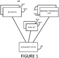
- the announced 3D printing system comprises a 3D printer, a build unit, and a material processing unit.
- the build unit is the module in which the 3D printer generates 3D objects using build material stored in the build unit.
- the material within the build unit may be loaded in the build unit by the material processing unit.
- the material processing unit also serves to remove unfused material from the build unit after processing by the 3D printer and also allows finished 3D printed articles to be removed. Unfused material may be recovered by the material processing unit to be reused to generate further 3D objects.
- the above-mentioned 3D printing system may be used in a variety of configurations, from small prototyping environments, to high production capacity industrial environments.
- Described herein are examples of a 3D printing management system to help increase the throughput capacity of such 3D printing systems.
- a management system will be of particular use in configurations where multiple elements, such as multiple build units, multiple 3D printers, and/or multiple material processing units are used.
- the 3D printing system 100 comprises one or multiple 3D printers 102a to 102n, one or multiple material processing units 104a to 104n, one or multiple build units 106a to 106n, and a management system 108.
- the three above-described elements of the 3D printing system i.e. the 3D printer, the build unit, and the material processing unit, are independent elements.
- independent elements is meant that there may be no physical connection between each of the elements. In examples there may be no direct communication possible between each of the elements.
- the material processing unit 104 loads build material into the build unit 106.
- the material processing unit 104 would have been previously supplied with a suitable build material, for example from one or multiple build material containers.
- Build material may be any suitable build material that is suitable for processing by the 3D printing system.
- the build material may be a powdered thermoplastic material, such as PA11 or PA12. In other examples powdered metals, powdered ceramics, and other suitable powdered build materials may be used.
- the 3D printer 102 may be able to generate 3D objects in a build unit loaded with different kinds of build material (e.g. with each build unit loaded with a single kind of build material at any one time).
- the material processing unit 104 may also be used to process different kinds of build material, but in one example may only process a single kind of build material at one time, to avoid contamination between different kinds of build material.
- the build unit 106 is removed from the material processing unit 104.
- the build unit 106 is inserted into the 3D printer 102.
- the 3D printer 102 executes a print job to generate an object or objects in the build unit.
- the build unit 106 is removed from the 3D printer.
- the contents of the build unit 106 may be allowed to cool, for example using natural cooling.
- the natural cooling phase may be omitted, and in other examples the natural cooling phase may be used to reduce the temperature of the contents of the build unit by a predetermined amount, for example between about 5 and 20%, between about 5 and 50%, or between about 5 and 95%.
- the build unit is inserted into the material processing unit.
- the material processing unit is used to extract unfused build material from the build unit and to allow the 3D printed objects in the build unit to be removed.
- the build unit 106 is a mobile unit that may be moved between the 3D printer 102 and the material processing station 104. At present, the build unit 106 may be moved manually by a user, although known automation systems, such as powered robots, could also be used to automatically move the build unit.
- either the 3D printer 102 or the material processing unit 104 may be idle whilst the build unit 106 is inserted into either the 3D printer 102 or the material processing unit 104. If a 3D print job takes, for example, between 5 to 10 hours to complete by the 3D printer 102 (depending, for example, on the size of the build volume in the build unit), this can lead to a large amount of idle time for the material processing unit 104. Similarly, if it takes 1 hour, for example, to process the build unit 106 in the material processing unit 104, the 3D printer 102 is idle during this time.
- Adding multiple build units 106 to the 3D printing system 100 enables production capacity to be increased since, for example, one build unit can be being processed by the 3D printer 102, whilst another build unit is being processed by the material processing unit 104. Adding further build units 106 enables further capacity increases and helps reduces idle time of elements of the 3D printing system.
- Adding multiple 3D printers 102 and multiple build units 106 to the 3D printing system 100 enables production capacity to be further increased by allowing, for example, multiple build units to each be processed by a different 3D printers at the same time.
- each material processing unit 104 may, for example, be used with a different kind of build material, which further increases the attractiveness of such 3D printing systems.
- adding additional elements to the 3D printing system 100 increases the complexity of managing workflow. It may also increase the likelihood of errors being made, for example, by inserting a build unit loaded with a first kind of build material into a material processing unit using a different kind of build material. Furthermore, having multiple identical or similar looking build units having different states of operation (such as: having being loaded with build material; having been processed by a 3D printer; at different stages of natural cooling; awaiting processing by a material processing unit; etc.) further complicates workflow management.
- the management system 108 aims to simplify workflow management within the printing system 100.
- the management system 108 may also allow the 3D printing system to be operated at a high level of efficiency.
- the management system 108 comprises a processor 302, such as a microprocessor.
- the processor 302 is coupled to a memory 304, for example via a suitable communication bus (not shown).
- the memory 304 stores processor understandable 3D printing system management instructions 306 that when executed by the processor 302 cause the processor 302 to control elements of the 3D printing system 100 as described in detail below.
- the management system 108 may also comprise additional elements such as user interfaces, visual display units, power supplies, and the like, which are not illustrated for the purposes of clarity.
- the management system 108 also comprises storage 308 for storing data related to the status of different ones of the elements of the 3D printing system 100.
- the storage may be part of the memory 304 within the management system 108.
- the storage 308 may be part of a separate storage or database that is accessible to the management system 108 via a suitable communications network.
- the storage 308 could be located within the 3D printing system 100, or could be located remotely and accessible via the Internet or other communications network.
- the processor 302 of the management system 108 executes instructions 306 to obtain status data from at least some of the elements of the 3D printing system 100.
- the management system 108 may be in wired or wireless communication with elements of the 3D printing system 100 and may either directly request, or pull, the data, for example through an appropriate application programmer interface (API) or other direct polling mechanism.
- API application programmer interface
- Such data may also be sent, or pushed, from different ones of the elements of the 3D printing system 100 directly to the management system 108.
- Such data may also be sent by different ones of the elements of the 3D printing system to an intermediate storage element, such as a cloud or network based storage facility, from which the management system 108 may indirectly obtain the status data.
- an intermediate storage element such as a cloud or network based storage facility
- a mix of direct and indirect, and push or pull mechanisms may be used.
- the term 'obtain data' is intended to cover any suitable mechanism for obtaining data.
- the 3D printer 102 and material processing unit 104 may be connected to a local area network (LAN), or may be connected to a wide area network (WAN) such as the Internet.
- LAN local area network
- WAN wide area network
- the management system 108 obtains status data from the 3D printer 102.
- the status data may include any or all of the following non-limiting examples:
- the management system 108 also obtains status data from the material processing unit 104.
- the status data may include any or all of the non-limiting following examples:
- the management system 108 also obtains status data from the build unit 106 inserted into a 3D printer 102 or a material processing unit 104 of the system 100.
- the status data incudes an identifier of the build unit and may include any or all of the following non-limiting examples:
- the build unit 106 uses a suitable wireless communication module to transmit and receive data.
- the build unit 106 has no electronic communication capability, in which case status data of the build unit 106 may be obtained, either directly or indirectly, either when the build unit 106 is inserted into either the 3D printer 102 or is inserted into the material processing unit 104.
- the 3D printer 102 and the material processing unit 104 may send or make available data relating to the build unit 106 to the management system 108.
- the status of the build unit 106 may be obtained manually, for example by a user through a suitable user interface of an appropriate computing device, who may manually enter the identifier of the build unit, or scan a barcode, RFID tag, or other suitable electronic identification means associated therewith.
- the status data of the build unit 106 may be manually entered on the portable computing and subsequently transmitted to the data storage 308.
- the processor 302 of the management system 108 executes instructions 306 to obtain data relating to a print job to be printed.
- the 3D printing system 102 is configured such that print jobs to be printed by a 3D printer are initially sent to the management system 108, which in turn may transmit the print job to an appropriate 3D printer in the 3D printing system 100 in accordance with a determined schedule, for example at a determined time.
- the management system 108 may store the print job, or a link to the print job until it is sent to a 3D printer.
- the 3D printing system 102 may be configured such that print jobs are sent directly to a chosen 3D printer, and metadata relating to the print job is also sent or made available to the management system 108.
- the management system 108 thus also obtains data or metadata relating to a print job to be printed by a 3D printer in the 3D printing system 100.
- the print job data may include any or all of the following non-limiting examples:
- the management system 108 determines a schedule of operations to be performed by different ones of the elements of the 3D printing system 100.
- the management system 108 may determine that a given print job should be printed in a given build unit 106 in a given 3D printer 102, and that post-processing of the build unit 106 should be performed by a given material processing unit 104. In addition to determining an order of operations the management system 108 may also determine timing data related to at least some of the operations. In one example the management system 108 generates scheduling data relating to both a 3D printer and a material processing unit. For example, the management system 108 may schedule a build unit to be used in a given 3D printer during a first timeframe, and may schedule the build unit to be used in a given material processing unit in a second timeframe different from the first timeframe.
- the management system 108 determines control data to allow enforcement of the determined schedule.
- the control data may be transmitted to at least some of the elements of the 3D printing system 100.
- the control data may be stored in the storage 308 to which elements of the 3D printing system 100 have access. In this way, for example, a material processing unit may determine from the control data whether it can process the build unit or not at the current time.
- the example process outlined in Figure 4 is a continuous process that may be performed regularly and repeatedly such that the management system 108 has up-to-date data available relating the different elements in the 3D printing system 100.
- the 3D printing system 100 comprises two 3D printers 102a and 102b, four build units 106a, 106b, 106c, and 106d, and one material processing unit 104a.
- Figure 5 shows an example visualization of a processing schedule 500 previously determined by the management system 108 based on data obtained from elements of the 3D printing system 100.
- Figure 5 shows one row for each of the elements in the 3D printing system 100, with a timeline shown along the x-axis.
- the first row 504 represents a schedule for a first 3D printer and the second row 506 represents a schedule for a second 3D printer.
- the third row 508 represents a schedule for a first material processing unit and the fourth row 510 represents a schedule for a second material processing unit.
- the fifth row 512 represents a schedule for a first build unit
- the sixth row 514 represents a schedule for a second build unit
- the seventh row 516 represents a schedule for a third build unit.
- Processing operations which are in progress or which have been completed are shown with a light shading, and future scheduled operations are shown with a darker shading.
- the current time (07:00) is represented by a dashed line 502.
- Future scheduled operations may be rescheduled by the management system 108 to take into account new print jobs which may be received, or by other changes in the status of elements of the 3D printing system.
- the management system determines (at block 406) how to schedule the newly received print job into the existing schedule.
- the new print job PJ2 specifies that it is to be printed using PA11 build material, which means that it can only be processed by material processing unit 1 (since material processing unit 2 is configured with PA12 build material).
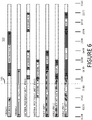
- the management system 108 has to determine a build unit to be assigned to the print job PJ2, and as seen in the schedule shown in Figure 5 , the first available build unit is build unit 3, which is free after 08:00.
- the management system 108 determines an updated schedule, as shown in Figure 6 . From this it can be seen that the management system 108 plans for build unit 1 to be loaded with PA11 build material from material processing unit 1, and for the build unit 3 be transferred to printer 1 where printing is expected to finish at 18:00. At 18:00 the management system 108 plans for build unit 1 to be transferred to material processing unit 1, where the build volume can be cooled and the 3D printed objects removed.
- the print job related data includes an urgency or other timing data that may indicate how the print job should be integrated into the current determined schedule. For example, if a newly received print job has a low urgency indicator, the management system 108 may schedule the print job to be executed after all current print jobs in the schedule. If, however, a newly received print job has an urgency higher than other print jobs for which processing has not yet started, the management system 108 may update the determined schedule such that the newly received print job is scheduled to be processed before other print jobs that have a lower priority.
- an urgency or other timing data may indicate how the print job should be integrated into the current determined schedule. For example, if a newly received print job has a low urgency indicator, the management system 108 may schedule the print job to be executed after all current print jobs in the schedule. If, however, a newly received print job has an urgency higher than other print jobs for which processing has not yet started, the management system 108 may update the determined schedule such that the newly received print job is scheduled to be processed before other print jobs that have a lower priority.
- control data is scheduling data relevant to at least the 3D printer system element to which it is sent or made available.
- control data sent to the 3D printer 1 may relate to scheduling data relevant only to printer 1
- control data sent to material processing unit 1 may relate to scheduling data relevant only to material processing unit 1.
- all or other portions of the determined scheduling may be sent or made available to different ones of the 3D printing system elements.
- control data is used to control elements of the 3D printing system not to perform operations which are not in accordance with the determined control data.
- the control data may include a 3D build unit identifier, an identifier of a 3D printing system element (i.e. either a 3D printer or a material processing unit) intended to process the identified build unit, and a time range during which the identified build unit may be processed by the identified 3D printing system element.
- the time range may be replaced by binary indicator generated by the management system 108 indicating whether the identified build unit may be processed at the current time.
- control data sent to material processing unit 1 indicates that at a given time build unit 3 is expected to be processed thereby, it will refuse to operate if build unit 2 is inserted thereinto at that time.
- control data sent to the material processing unit 1 will prevent processing of build unit 2 whilst it is loaded with PA12 build material.
- the 3D printer 700 comprises a suitable 3D printing module 702, and a processor 704, such as a microprocessor, coupled to a memory 706.
- the memory 706 stores processor understandable scheduling control instructions 708.
- the instructions 708 control the 3D printing module 702 according to scheduling data 710.
- the scheduling data 710 may have been sent to or made available to the 3D printer 700 by management system 108.
- Example operation of the 3D printer 700 is described with further reference to the flow diagram of Figure 8 .
- the processor 704 executes the scheduling control instructions 708 and obtains scheduling data 710.
- the processor 704 processes the obtained scheduling data and controls operation of the 3D printer 700 in accordance with the scheduling data, for example as described above.
- the 3D printer 700 performs a check against any control data prior to performing any print job on a build unit inserted thereinto to ensure that it is in compliance with any scheduling control data.
- the material processing unit 900 comprises a suitable material processing module 902, and a processor 904, such as a microprocessor coupled to a memory 906.
- the memory 904 stores processor understandable scheduling control instructions 908.
- the instructions 908 control the material processing module 902 according to scheduling data 910.
- the scheduling data 910 may have be sent to or made available to the material processing unit 900 by management system 108.
- Example operation of the material processing unit 900 is described with further reference to the flow diagram of Figure 10 .
- the processor 904 executes the scheduling control instructions 908 and obtains scheduling data 910.
- the processor 904 processes the obtained scheduling data and controls operation of the material processing unit 900 in accordance with the scheduling data, for example as described above.
- the material processing unit 900 performs a check against any control data prior to processing a build unit inserted thereinto to ensure that it is in compliance with any scheduling control data.
- elements of the 3D printing system may be assisted by a visual representation of the determined scheduling, for example displayed on a visual display of a suitable computing device.
- elements of the 3D printing system may be configured to alert a user, for example using an audible or visual alert, if a user tries to operate elements of the 3D printing system in a way that does not respect the determined scheduling.
- Such a management system becomes increasingly important as the complexity and production capacity of 3D printing systems increases. For example, the efficient management of a 3D printing system having multiple 3D printers, multiple build units, and/or multiple material processing units quickly becomes beyond what is manageable by a human operator. Furthermore, such systems may be operated by multiple human operators further complicating the task.
- example described herein can be realized in the form of hardware, software or a combination of hardware and software. Any such software may be stored in the form of volatile or non-volatile storage such as, for example, a storage device like a ROM, whether erasable or rewritable or not, or in the form of memory such as, for example, RAM, memory chips, device or integrated circuits or on an optically or magnetically readable medium such as, for example, a CD, DVD, magnetic disk or magnetic tape. It will be appreciated that the storage devices and storage media are examples of machine-readable storage that are suitable for storing a program or programs that, when executed, implement examples described herein.
- some examples provide a program comprising code for implementing a system or method as claimed in any preceding claim and a machine readable storage storing such a program. Still further, some examples of the present invention may be conveyed electronically via any medium such as a communication signal carried over a wired or wireless connection.
Landscapes
- Engineering & Computer Science (AREA)
- Chemical & Material Sciences (AREA)
- Physics & Mathematics (AREA)
- Materials Engineering (AREA)
- Theoretical Computer Science (AREA)
- Manufacturing & Machinery (AREA)
- General Engineering & Computer Science (AREA)
- General Physics & Mathematics (AREA)
- Optics & Photonics (AREA)
- Mechanical Engineering (AREA)
- Human Computer Interaction (AREA)
- Automation & Control Theory (AREA)
- Quality & Reliability (AREA)
- Ceramic Engineering (AREA)
Description
- Additive manufacturing systems, generally referred to as 3D printing systems, may be useful in generating generally low quantities of certain types of objects. At present, traditional manufacturing techniques, such as injection molding, may be considered to be more efficient for generating large quantities of certain types of objects.
-
US 2016/0082652 A1 describes a system including a manufacturing device to perform at least one additive manufacturing process and to include a prefabricated component during the at least one additive manufacturing process.US 2017/0334134 discloses a production system for simultaneous additive manufacturing of multiple components including self driven transport means which can be directed and controlled by the production system control apparatus such that they can insert construction containers into a process chamber.US 2015/0057784 discloses a method of optimizing scheduling in 3D printing by segmenting and or combining input jobs.DE102014016718 discloses a production system for 3D printers comprising a removable process chamber. - The invention is set out in the appended claims.
- Examples will now be described, by way of non-limiting example only, with reference to the accompanying drawings, in which:
-
Figure 1 is a block diagram of a 3D printing system according to one example; -
Figure 2 is a flow diagram outlining an example workflow according to which a 3D printing system may be operated; -
Figure 3 is a block diagram of a 3D printing management system according to one example; -
Figure 4 is a flow diagram outlining a method of operating a 3D printing management system according to one example; -
Figure 5 is an illustration of a generated schedule according to one example; -
Figure 6 is an illustration of a generated schedule according to one example; -
Figure 7 is a block diagram of a 3D printer according to one example; -
Figure 8 is a flow diagram outlining an example method of controlling operation of a 3D printer according to scheduling data; -
Figure 9 is a block diagram of a material processing unit according to one example; and -
Figure 10 is a flow diagram outlining an example method of controlling operation of a material processing unit according to scheduling data. - As the availability of high-speed and
high quality 3D printing systems increases, so does the prospect of 3D printers replacing at least some traditional manufacturing techniques. However, in order to drive the large-scale adoption of 3D printing in the industrial manufacturing space the competitivity of such 3D printing systems has to be increased. - An example 3D printing system was announced by HP Inc. on May 17 2016. The announced 3D printing system comprises a 3D printer, a build unit, and a material processing unit. The build unit is the module in which the 3D printer generates 3D objects using build material stored in the build unit. The material within the build unit may be loaded in the build unit by the material processing unit. The material processing unit also serves to remove unfused material from the build unit after processing by the 3D printer and also allows finished 3D printed articles to be removed. Unfused material may be recovered by the material processing unit to be reused to generate further 3D objects.
- Due to its modular nature, the above-mentioned 3D printing system may be used in a variety of configurations, from small prototyping environments, to high production capacity industrial environments.
- Described herein are examples of a 3D printing management system to help increase the throughput capacity of such 3D printing systems. Such a management system will be of particular use in configurations where multiple elements, such as multiple build units, multiple 3D printers, and/or multiple material processing units are used.
- Referring now to
Figure 1 , there is shown a3D printing system 100 according to one example. The3D printing system 100 comprises one ormultiple 3D printers 102a to 102n, one or multiplematerial processing units 104a to 104n, one ormultiple build units 106a to 106n, and amanagement system 108. - The three above-described elements of the 3D printing system, i.e. the 3D printer, the build unit, and the material processing unit, are independent elements. By independent elements is meant that there may be no physical connection between each of the elements. In examples there may be no direct communication possible between each of the elements.
- An example workflow of how the
3D printing system 100 may be operated which is useful for understanding the invention is described below with additional reference toFigure 2 . In this example only a single 3D printer, a single build unit, and a single material processing unit are described. - At 202 an
empty build unit 106 is inserted into the material processing unit 104. - At 204 the material processing unit 104 loads build material into the
build unit 106. The material processing unit 104 would have been previously supplied with a suitable build material, for example from one or multiple build material containers. Build material may be any suitable build material that is suitable for processing by the 3D printing system. In one example, the build material may be a powdered thermoplastic material, such as PA11 or PA12. In other examples powdered metals, powdered ceramics, and other suitable powdered build materials may be used. - The 3D printer 102 may be able to generate 3D objects in a build unit loaded with different kinds of build material (e.g. with each build unit loaded with a single kind of build material at any one time). The material processing unit 104 may also be used to process different kinds of build material, but in one example may only process a single kind of build material at one time, to avoid contamination between different kinds of build material.
- At 206 the
build unit 106 is removed from the material processing unit 104. - At 208 the
build unit 106 is inserted into the 3D printer 102. - At 210 the 3D printer 102 executes a print job to generate an object or objects in the build unit.
- At 212, when the print job has been executed, the
build unit 106 is removed from the 3D printer. - At 214, the contents of the
build unit 106 may be allowed to cool, for example using natural cooling. In some examples, however, the natural cooling phase may be omitted, and in other examples the natural cooling phase may be used to reduce the temperature of the contents of the build unit by a predetermined amount, for example between about 5 and 20%, between about 5 and 50%, or between about 5 and 95%. - At 216 the build unit is inserted into the material processing unit.
- At 218 the material processing unit is used to extract unfused build material from the build unit and to allow the 3D printed objects in the build unit to be removed.
- The
build unit 106 is a mobile unit that may be moved between the 3D printer 102 and the material processing station 104. At present, thebuild unit 106 may be moved manually by a user, although known automation systems, such as powered robots, could also be used to automatically move the build unit. - In a 3D printing system with just a
single build unit 106, a single 3D printer 102, and a single material processing unit 104, control of the workflow is relatively straightforward. - With a
single build unit 106, either the 3D printer 102 or the material processing unit 104 may be idle whilst thebuild unit 106 is inserted into either the 3D printer 102 or the material processing unit 104. If a 3D print job takes, for example, between 5 to 10 hours to complete by the 3D printer 102 (depending, for example, on the size of the build volume in the build unit), this can lead to a large amount of idle time for the material processing unit 104. Similarly, if it takes 1 hour, for example, to process thebuild unit 106 in the material processing unit 104, the 3D printer 102 is idle during this time. - Adding
multiple build units 106 to the3D printing system 100 enables production capacity to be increased since, for example, one build unit can be being processed by the 3D printer 102, whilst another build unit is being processed by the material processing unit 104. Addingfurther build units 106 enables further capacity increases and helps reduces idle time of elements of the 3D printing system. - Adding multiple 3D printers 102 and
multiple build units 106 to the3D printing system 100 enables production capacity to be further increased by allowing, for example, multiple build units to each be processed by a different 3D printers at the same time. - Adding multiple material processing units 104, multiple 3D printers 102, and
multiple build units 106 to the3D printing system 100 enables production capacity to be yet further increased. In this way, each material processing unit 104 may, for example, be used with a different kind of build material, which further increases the attractiveness of such 3D printing systems. - However, adding additional elements to the
3D printing system 100 increases the complexity of managing workflow. It may also increase the likelihood of errors being made, for example, by inserting a build unit loaded with a first kind of build material into a material processing unit using a different kind of build material. Furthermore, having multiple identical or similar looking build units having different states of operation (such as: having being loaded with build material; having been processed by a 3D printer; at different stages of natural cooling; awaiting processing by a material processing unit; etc.) further complicates workflow management. - As described below and as shown in more detail in
Figure 3 , themanagement system 108 aims to simplify workflow management within theprinting system 100. Themanagement system 108 may also allow the 3D printing system to be operated at a high level of efficiency. Themanagement system 108 comprises aprocessor 302, such as a microprocessor. Theprocessor 302 is coupled to amemory 304, for example via a suitable communication bus (not shown). Thememory 304 stores processor understandable 3D printingsystem management instructions 306 that when executed by theprocessor 302 cause theprocessor 302 to control elements of the3D printing system 100 as described in detail below. It will be appreciated that themanagement system 108 may also comprise additional elements such as user interfaces, visual display units, power supplies, and the like, which are not illustrated for the purposes of clarity. - The
management system 108 also comprisesstorage 308 for storing data related to the status of different ones of the elements of the3D printing system 100. In one example the storage may be part of thememory 304 within themanagement system 108. In another example thestorage 308 may be part of a separate storage or database that is accessible to themanagement system 108 via a suitable communications network. For example, thestorage 308 could be located within the3D printing system 100, or could be located remotely and accessible via the Internet or other communications network. - An example operation of the
3D printing system 100 will now be described with reference to the flow diagram ofFigure 4 . - At
block 402 theprocessor 302 of themanagement system 108 executesinstructions 306 to obtain status data from at least some of the elements of the3D printing system 100. - As will be appreciated, there are numerous ways in which such status data may be obtained. For example, the
management system 108 may be in wired or wireless communication with elements of the3D printing system 100 and may either directly request, or pull, the data, for example through an appropriate application programmer interface (API) or other direct polling mechanism. Such data may also be sent, or pushed, from different ones of the elements of the3D printing system 100 directly to themanagement system 108. Such data may also be sent by different ones of the elements of the 3D printing system to an intermediate storage element, such as a cloud or network based storage facility, from which themanagement system 108 may indirectly obtain the status data. In some examples a mix of direct and indirect, and push or pull mechanisms may be used. As used herein the term 'obtain data' is intended to cover any suitable mechanism for obtaining data. - For example, in the present example the 3D printer 102 and material processing unit 104 may be connected to a local area network (LAN), or may be connected to a wide area network (WAN) such as the Internet.
- The
management system 108 obtains status data from the 3D printer 102. The status data may include any or all of the following non-limiting examples: - A printer identifier;
- The operational state of the printer (e.g. printing, idle, awaiting maintenance, etc.);
- If printing, estimated end of printing time; and
- Types of build material with which the printer can operate.
- The
management system 108 also obtains status data from the material processing unit 104. The status data may include any or all of the non-limiting following examples: - An identifier of the material processing unit;
- The operational state of the unit (e.g. in-use, idle, awaiting maintenance, etc.);
- If in-use, estimated end time; and
- Type of build material loaded in the material processing unit
- The
management system 108 also obtains status data from thebuild unit 106 inserted into a 3D printer 102 or a material processing unit 104 of thesystem 100. The status data incudes an identifier of the build unit and may include any or all of the following non-limiting examples: - Operational state of the unit (e.g. ready for printing, inserted in printer, inserted in material processing unit, not inserted into either printer or material processing unit; undergoing cooling, etc.)
- Build material type loaded in the build unit
- In one example the
build unit 106 uses a suitable wireless communication module to transmit and receive data. In another example, thebuild unit 106 has no electronic communication capability, in which case status data of thebuild unit 106 may be obtained, either directly or indirectly, either when thebuild unit 106 is inserted into either the 3D printer 102 or is inserted into the material processing unit 104. For example, the 3D printer 102 and the material processing unit 104 may send or make available data relating to thebuild unit 106 to themanagement system 108. - In another example, the status of the
build unit 106 may be obtained manually, for example by a user through a suitable user interface of an appropriate computing device, who may manually enter the identifier of the build unit, or scan a barcode, RFID tag, or other suitable electronic identification means associated therewith. The status data of thebuild unit 106 may be manually entered on the portable computing and subsequently transmitted to thedata storage 308. - At
block 404 theprocessor 302 of themanagement system 108 executesinstructions 306 to obtain data relating to a print job to be printed. In one example the 3D printing system 102 is configured such that print jobs to be printed by a 3D printer are initially sent to themanagement system 108, which in turn may transmit the print job to an appropriate 3D printer in the3D printing system 100 in accordance with a determined schedule, for example at a determined time. In one example themanagement system 108 may store the print job, or a link to the print job until it is sent to a 3D printer. In another example, the 3D printing system 102 may be configured such that print jobs are sent directly to a chosen 3D printer, and metadata relating to the print job is also sent or made available to themanagement system 108. - The
management system 108 thus also obtains data or metadata relating to a print job to be printed by a 3D printer in the3D printing system 100. The print job data may include any or all of the following non-limiting examples: - A print job identifier;
- The build material to be used (e.g. material type, acceptable or desired ratio of fresh to recycled build material);
- The size of the build volume;
- The number of objects to be printed;
- The estimated or desired cooling time after printing;
- An urgency indicator; and
- Details of any post-processing operations to be performed.
- At
block 406 themanagement system 108 determines a schedule of operations to be performed by different ones of the elements of the3D printing system 100. - For example, the
management system 108 may determine that a given print job should be printed in a givenbuild unit 106 in a given 3D printer 102, and that post-processing of thebuild unit 106 should be performed by a given material processing unit 104. In addition to determining an order of operations themanagement system 108 may also determine timing data related to at least some of the operations. In one example themanagement system 108 generates scheduling data relating to both a 3D printer and a material processing unit. For example, themanagement system 108 may schedule a build unit to be used in a given 3D printer during a first timeframe, and may schedule the build unit to be used in a given material processing unit in a second timeframe different from the first timeframe. - At
block 408, themanagement system 108 determines control data to allow enforcement of the determined schedule. In one example the control data may be transmitted to at least some of the elements of the3D printing system 100. In another example the control data may be stored in thestorage 308 to which elements of the3D printing system 100 have access. In this way, for example, a material processing unit may determine from the control data whether it can process the build unit or not at the current time. - The example process outlined in
Figure 4 is a continuous process that may be performed regularly and repeatedly such that themanagement system 108 has up-to-date data available relating the different elements in the3D printing system 100. - A more detailed workflow in accordance with the above-described examples will now be described. In this example the
3D printing system 100 comprises two3D printers 102a and 102b, fourbuild units 106a, 106b, 106c, and 106d, and onematerial processing unit 104a.Figure 5 shows an example visualization of aprocessing schedule 500 previously determined by themanagement system 108 based on data obtained from elements of the3D printing system 100. -
Figure 5 shows one row for each of the elements in the3D printing system 100, with a timeline shown along the x-axis. For example, thefirst row 504 represents a schedule for a first 3D printer and thesecond row 506 represents a schedule for a second 3D printer. Thethird row 508 represents a schedule for a first material processing unit and thefourth row 510 represents a schedule for a second material processing unit. Thefifth row 512 represents a schedule for a first build unit, thesixth row 514 represents a schedule for a second build unit, and theseventh row 516 represents a schedule for a third build unit. - Processing operations which are in progress or which have been completed are shown with a light shading, and future scheduled operations are shown with a darker shading. The current time (07:00) is represented by a dashed
line 502. Future scheduled operations may be rescheduled by themanagement system 108 to take into account new print jobs which may be received, or by other changes in the status of elements of the 3D printing system. - A summary of the data shown in the
schedule 500 is shown in the tables below:ELEMENT (ID) COMPATIBLE MATERIAL TYPE STATUS BUILD UNIT USED ADDITIONAL DATA PRINTER 1 (P1) PA11 & PA12 IDLE - - PRINTER 2 (P2) PA12 & PA12 PRINTING PJ1 BU1 FREE AT: 10:00 ELEMENT (ID) MATERIAL TYPE STATUS ADDITIONAL DATA MATERIAL PROCESSING UNIT 1 (MPU1) PA11 PROCESSING BUILD UNIT 1FREE UNTIL: 10:00 MATERIAL PROCESSING UNIT 2 (MPU2) PA12 PROCESSING BU3 FREE AT: 08:00 ELEMENT (ID) MATERIAL TYPE STATUS ADDITIONAL DATA BUILD UNIT 1 (BU1) PA11 IN USE FREE AT: 14:00 BUILD UNIT 2 (BU2) PA11 NATURAL COOLING FREE AT: 12:00 BUILD UNIT 3 (BU3) PA12 IN USE FREE AT: 08:00 PRINTJOB ID MATERIAL TYPE STATUS OTHER PJ1 PA11 IN PROGRESS - - If, at 07:00 a new print job is received (for example at
block 404 described above), the management system determines (at block 406) how to schedule the newly received print job into the existing schedule.PRINTJOB ID MATERIAL TYPE STATUS OTHER PJ2 PA11 QUEUED - - For example, the new print job PJ2 specifies that it is to be printed using PA11 build material, which means that it can only be processed by material processing unit 1 (since
material processing unit 2 is configured with PA12 build material). Themanagement system 108 has to determine a build unit to be assigned to the print job PJ2, and as seen in the schedule shown inFigure 5 , the first available build unit isbuild unit 3, which is free after 08:00. - The
management system 108 then determines an updated schedule, as shown inFigure 6 . From this it can be seen that themanagement system 108 plans forbuild unit 1 to be loaded with PA11 build material frommaterial processing unit 1, and for thebuild unit 3 be transferred toprinter 1 where printing is expected to finish at 18:00. At 18:00 themanagement system 108 plans forbuild unit 1 to be transferred tomaterial processing unit 1, where the build volume can be cooled and the 3D printed objects removed. - The way in which the schedule shown in
Figures 5 andFigure 6 is determined may be performed in a multitude of ways, using any suitable scheduling algorithms. - In one example, the print job related data includes an urgency or other timing data that may indicate how the print job should be integrated into the current determined schedule. For example, if a newly received print job has a low urgency indicator, the
management system 108 may schedule the print job to be executed after all current print jobs in the schedule. If, however, a newly received print job has an urgency higher than other print jobs for which processing has not yet started, themanagement system 108 may update the determined schedule such that the newly received print job is scheduled to be processed before other print jobs that have a lower priority. - However, at described at
block 408, once a suitable schedule has been determined themanagement system 108 generates control data to allow enforcement of the determined schedule. In one example, the control data is scheduling data relevant to at least the 3D printer system element to which it is sent or made available. For example, the control data sent to the3D printer 1 may relate to scheduling data relevant only toprinter 1, whereas control data sent tomaterial processing unit 1 may relate to scheduling data relevant only tomaterial processing unit 1. In other examples, however, all or other portions of the determined scheduling may be sent or made available to different ones of the 3D printing system elements. - The control data is used to control elements of the 3D printing system not to perform operations which are not in accordance with the determined control data. In one example, the control data may include a 3D build unit identifier, an identifier of a 3D printing system element (i.e. either a 3D printer or a material processing unit) intended to process the identified build unit, and a time range during which the identified build unit may be processed by the identified 3D printing system element. In another example, the time range may be replaced by binary indicator generated by the
management system 108 indicating whether the identified build unit may be processed at the current time. - For example, if control data sent to
material processing unit 1 indicates that at a giventime build unit 3 is expected to be processed thereby, it will refuse to operate ifbuild unit 2 is inserted thereinto at that time. By way of another example, if a print job P3 specifies that PA12 build material be used, and thatbuild unit 2 is assigned print job P3, the control data sent to thematerial processing unit 1 will prevent processing ofbuild unit 2 whilst it is loaded with PA12 build material. - An
example 3D printer 700 is illustrated inFigure 7 . The3D printer 700 comprises a suitable3D printing module 702, and aprocessor 704, such as a microprocessor, coupled to amemory 706. Thememory 706 stores processor understandablescheduling control instructions 708. When executed by theprocessor 704, theinstructions 708 control the3D printing module 702 according toscheduling data 710. As described above thescheduling data 710 may have been sent to or made available to the3D printer 700 bymanagement system 108. - Example operation of the
3D printer 700 is described with further reference to the flow diagram ofFigure 8 . - At
block 802, theprocessor 704 executes thescheduling control instructions 708 and obtainsscheduling data 710. - At
block 804, theprocessor 704 processes the obtained scheduling data and controls operation of the3D printer 700 in accordance with the scheduling data, for example as described above. In this example, the3D printer 700 performs a check against any control data prior to performing any print job on a build unit inserted thereinto to ensure that it is in compliance with any scheduling control data. - An example
material processing unit 900 is illustrated inFigure 9 . Thematerial processing unit 900 comprises a suitablematerial processing module 902, and aprocessor 904, such as a microprocessor coupled to amemory 906. Thememory 904 stores processor understandablescheduling control instructions 908. When executed by theprocessor 904, theinstructions 908 control thematerial processing module 902 according toscheduling data 910. As described above thescheduling data 910 may have be sent to or made available to thematerial processing unit 900 bymanagement system 108. - Example operation of the
material processing unit 900 is described with further reference to the flow diagram ofFigure 10 . - At
block 1002, theprocessor 904 executes thescheduling control instructions 908 and obtainsscheduling data 910. - At block 1004, the
processor 904 processes the obtained scheduling data and controls operation of thematerial processing unit 900 in accordance with the scheduling data, for example as described above. In this example, thematerial processing unit 900 performs a check against any control data prior to processing a build unit inserted thereinto to ensure that it is in compliance with any scheduling control data. - The control of elements of the 3D printing system in this way may be assisted by a visual representation of the determined scheduling, for example displayed on a visual display of a suitable computing device. Furthermore, elements of the 3D printing system may be configured to alert a user, for example using an audible or visual alert, if a user tries to operate elements of the 3D printing system in a way that does not respect the determined scheduling.
- Such a management system becomes increasingly important as the complexity and production capacity of 3D printing systems increases. For example, the efficient management of a 3D printing system having multiple 3D printers, multiple build units, and/or multiple material processing units quickly becomes beyond what is manageable by a human operator. Furthermore, such systems may be operated by multiple human operators further complicating the task.
- It will be appreciated that example described herein can be realized in the form of hardware, software or a combination of hardware and software. Any such software may be stored in the form of volatile or non-volatile storage such as, for example, a storage device like a ROM, whether erasable or rewritable or not, or in the form of memory such as, for example, RAM, memory chips, device or integrated circuits or on an optically or magnetically readable medium such as, for example, a CD, DVD, magnetic disk or magnetic tape. It will be appreciated that the storage devices and storage media are examples of machine-readable storage that are suitable for storing a program or programs that, when executed, implement examples described herein. Accordingly, some examples provide a program comprising code for implementing a system or method as claimed in any preceding claim and a machine readable storage storing such a program. Still further, some examples of the present invention may be conveyed electronically via any medium such as a communication signal carried over a wired or wireless connection.
Claims (11)
- A 3D printing system (100) comprising at least one build unit (106) in which 3D objects can be generated by a 3D printer (102), a management system (108) to control the 3D printing system (100), a 3D printer (102) and a material processing unit (104) in which processing operations can be performed on the build unit, the management system comprising:a processor (308) configured to:obtain status data from at least some of the elements of the 3D printing system, including obtaining status data relating to a build unit inserted into a 3D printer (102) or a material processing unit (104) of the system (100), the status data relating to the build unit comprising an identifier of the build unit;obtain data relating to a print job to be printed;determine, from the obtained data, a schedule of operations to be performed by elements of the 3D printing system and;generate control data to allow enforcement of the determined schedule, wherein the processor is to generate control data that includes: the identifier of the build unit, anidentifier of either the 3D printer or the material processing unit intended to process the identified build unit; and an indication of whether the identified build unit may be used at the current time; andsend or make available the generated control data to at least one of the 3D printer (102) and material processing unit (104);and wherein the 3D printer (102) or the material processing unit (104) into which the build unit (106) is inserted is configured to perform a check against the control data prior to processing the build unit inserted thereinto to ensure that it is in compliance with the control data, and the 3D printer (102) or the material processing unit (104) into which the build unit (106) is inserted is not to perform operations which are not in accordance with the control data.
- The system of claim 1, wherein the processor is configured to obtain print job data and forward the print job data to a 3D printer in the 3D printing system in accordance with the determined schedule of operations.
- The system of claim 1, wherein the processor is configured to obtain status data relating to a build unit indirectly from one of a 3D printer or a material processing unit.
- The system of claim 1, wherein the processor is configured to obtain status data relating to a build unit from a separate computing device on which status data of the build unit is entered manually.
- The system of claim 1, wherein the processor is configured to obtain status data relating to a build unit directly from the build unit.
- The system of claim 1, wherein the processor is configured to generate a visualization of the generated schedule on a visual display unit.
- A method of managing operation of a 3D printing system (100) comprising at least one 3D printer (102), at least one build unit (106), and at least one material processing unit (104); comprising:obtaining (402) status data of elements of the 3D printing system including obtaining status data relating to a build unit inserted into a 3D printer (102) or a material processing unit (104) of the system (100), the status data relating to the build unit comprising an identifier of the build unit;obtaining (404) data relating to a print job to be performed by a 3D printer;determining (406) a schedule of operations to be performed by elements of the 3D printing system; andgenerating (408) control data to allow the 3D printer or the material processing unit to enforce the determined schedule, wherein generating the control data comprises generating control data that includes: the identifier of the build unit, an identifier of either the 3D printer or the material processing unit intended to process the identified build unit; and an indication of whether the identified build unit may be used at the current time, the method further comprising:making available the generated control data to the 3D printer or the material processing unit to enable enforcement of the determined schedule; andperforming, by the 3D printer (102) or the material processing unit (104) into which the build unit (106) is inserted, a check against the control data prior to processing the build unit inserted thereinto to ensure that it is in compliance with the control data, and the 3D printer (102) or the material processing unit (104) into which the build unit (106) is inserted is not to perform operations which are not in accordance with the determined control data.
- The method of claim of claim 7, further comprising obtaining status data of the at least one build unit directly from the build unit.
- The method of claim 7, further comprising obtaining status data of the at least one build unit indirectly.
- The method of claim 7, wherein obtaining data relating to a print job comprises obtaining a print job file, and forwarding it to a 3D printer in accordance with the determined schedule.
- The method of claim 7, further comprising obtaining data relating to a further print job, and updating the determined schedule of operations and control data based on the further print job.
Applications Claiming Priority (1)
| Application Number | Priority Date | Filing Date | Title |
|---|---|---|---|
| PCT/EP2016/064933 WO2018001454A1 (en) | 2016-06-28 | 2016-06-28 | Management of 3d printing |
Publications (2)
| Publication Number | Publication Date |
|---|---|
| EP3433716A1 EP3433716A1 (en) | 2019-01-30 |
| EP3433716B1 true EP3433716B1 (en) | 2022-11-09 |
Family
ID=56360369
Family Applications (1)
| Application Number | Title | Priority Date | Filing Date |
|---|---|---|---|
| EP16735604.7A Active EP3433716B1 (en) | 2016-06-28 | 2016-06-28 | Management of 3d printing |
Country Status (6)
| Country | Link |
|---|---|
| US (2) | US10635368B2 (en) |
| EP (1) | EP3433716B1 (en) |
| JP (1) | JP7015248B2 (en) |
| KR (1) | KR20180124137A (en) |
| CN (1) | CN109074230B (en) |
| WO (1) | WO2018001454A1 (en) |
Families Citing this family (11)
| Publication number | Priority date | Publication date | Assignee | Title |
|---|---|---|---|---|
| CN109070452B (en) * | 2016-05-12 | 2021-06-22 | 惠普发展公司,有限责任合伙企业 | Additive manufacturing system and method for post-processing |
| US10759111B2 (en) * | 2017-04-14 | 2020-09-01 | Desktop Metal, Inc. | Smart cart for three dimensional binder jet printers |
| WO2019209301A1 (en) | 2018-04-26 | 2019-10-31 | Hewlett-Packard Development Company, L.P. | Printing production quality prediction |
| US10363705B1 (en) * | 2018-10-12 | 2019-07-30 | Capital One Services, Llc | Determining a printing anomaly related to a 3D printed object |
| NL2022029B1 (en) * | 2018-11-20 | 2020-06-03 | Additive Ind Bv | System comprising an apparatus for producing an object by means of additive manufacturing and a method for producing an object by means of additive manufacturing using an apparatus. |
| US11858064B2 (en) | 2019-02-19 | 2024-01-02 | Illinois Tool Works Inc. | Path planning systems and methods for additive manufacturing |
| WO2020178453A1 (en) * | 2019-03-07 | 2020-09-10 | Rapid Shape Gmbh | Method and system for producing a three-dimensional object |
| WO2021086318A1 (en) * | 2019-10-29 | 2021-05-06 | Hewlett-Packard Development Company, L.P. | Generation of print configuration data for three dimensional printers |
| DE102020115208A1 (en) | 2020-06-08 | 2021-12-09 | Eos Gmbh Electro Optical Systems | Method for generating an irradiation control data set for a device for additive manufacturing |
| AU2021401816A1 (en) * | 2020-12-18 | 2023-06-22 | Strong Force Vcn Portfolio 2019, Llc | Robot fleet management and additive manufacturing for value chain networks |
| DE102022109945A1 (en) | 2022-04-25 | 2023-10-26 | Eos Gmbh Electro Optical Systems | Dynamic assignment of objects to be manufactured to additive manufacturing devices |
Citations (2)
| Publication number | Priority date | Publication date | Assignee | Title |
|---|---|---|---|---|
| US20150057784A1 (en) * | 2013-08-21 | 2015-02-26 | Microsoft Corporation | Optimizing 3d printing using segmentation or aggregation |
| DE102014016718A1 (en) * | 2014-11-13 | 2016-05-19 | Cl Schutzrechtsverwaltungs Gmbh | Production plant for the simultaneous, generative production of several components |
Family Cites Families (26)
| Publication number | Priority date | Publication date | Assignee | Title |
|---|---|---|---|---|
| US1005282A (en) | 1911-02-06 | 1911-10-10 | Ellsworth A Murray | Bucket-chain. |
| US5622577A (en) | 1995-08-28 | 1997-04-22 | Delco Electronics Corp. | Rapid prototyping process and cooling chamber therefor |
| WO2004096556A2 (en) | 2003-04-28 | 2004-11-11 | Matsushita Electric Industrial Co. Ltd. | Nozzle head, line head using the same, and ink jet recording apparatus mounted with its line head |
| DE10342882A1 (en) | 2003-09-15 | 2005-05-19 | Trumpf Werkzeugmaschinen Gmbh + Co. Kg | Apparatus and method for producing a three-dimensional shaped body |
| US7790096B2 (en) | 2005-03-31 | 2010-09-07 | 3D Systems, Inc. | Thermal management system for a removable build chamber for use with a laser sintering system |
| US7621733B2 (en) | 2005-09-30 | 2009-11-24 | 3D Systems, Inc. | Rapid prototyping and manufacturing system and method |
| US7979152B2 (en) | 2006-05-26 | 2011-07-12 | Z Corporation | Apparatus and methods for handling materials in a 3-D printer |
| US20100155985A1 (en) | 2008-12-18 | 2010-06-24 | 3D Systems, Incorporated | Apparatus and Method for Cooling Part Cake in Laser Sintering |
| CN104827774B (en) | 2009-05-18 | 2017-08-08 | Xjet有限公司 | The method and device printed on heated base material |
| US8562324B2 (en) * | 2010-08-18 | 2013-10-22 | Makerbot Industries, Llc | Networked three-dimensional printing |
| JP2013049137A (en) * | 2011-08-30 | 2013-03-14 | Sony Corp | Powder removing apparatus, molding system, and method of manufacturing molded object |
| JP5815346B2 (en) * | 2011-09-20 | 2015-11-17 | 株式会社キーエンス | 3D modeling apparatus and modeling system |
| US9134675B2 (en) * | 2013-06-27 | 2015-09-15 | Xerox Corporation | Predicting remaining useful life for a consumable using a weighted least square regression prediction technique |
| JP5813720B2 (en) * | 2013-10-10 | 2015-11-17 | シャープ株式会社 | Image forming apparatus and operation method thereof |
| US10705509B2 (en) * | 2013-10-21 | 2020-07-07 | Made In Space, Inc. | Digital catalog for manufacturing |
| KR102223280B1 (en) * | 2014-07-16 | 2021-03-05 | 엘지전자 주식회사 | Mobile terminal |
| US10052822B1 (en) * | 2014-08-01 | 2018-08-21 | Amazon Technologies, Inc. | Selective pausing of 3D print jobs |
| EP3461622A1 (en) | 2014-11-24 | 2019-04-03 | Additive Industries B.V. | Apparatus and method for producing an object by means of additive manufacturing |
| DE102015201796B3 (en) * | 2015-02-03 | 2016-06-02 | MTU Aero Engines AG | Powder application unit and corresponding device and use of a powder application unit |
| CN105259879B (en) * | 2015-10-28 | 2017-08-11 | 成都博睿德科技有限公司 | 3D printer tele-control system |
| CN205202183U (en) * | 2015-11-03 | 2016-05-04 | 深圳长朗三维科技有限公司 | 3d printing system |
| CN105291440B (en) * | 2015-11-30 | 2017-12-01 | 浙江工业大学 | A kind of 3D printing system for supporting cloud service |
| JP6789646B2 (en) * | 2016-03-11 | 2020-11-25 | キヤノン株式会社 | Information processing equipment, control methods, and programs |
| EP3433082A1 (en) * | 2016-07-12 | 2019-01-30 | Hewlett-Packard Development Company, L.P. | Material processing unit for 3d printed parts |
| CN110809520B (en) * | 2017-10-13 | 2021-10-01 | 惠普发展公司,有限责任合伙企业 | Consumable comprising a locking mechanism |
| JP7118652B2 (en) * | 2018-01-22 | 2022-08-16 | キヤノン株式会社 | Image forming apparatus and control method |
-
2016
- 2016-06-28 EP EP16735604.7A patent/EP3433716B1/en active Active
- 2016-06-28 JP JP2018556860A patent/JP7015248B2/en active Active
- 2016-06-28 KR KR1020187031547A patent/KR20180124137A/en not_active Application Discontinuation
- 2016-06-28 US US16/096,355 patent/US10635368B2/en active Active
- 2016-06-28 WO PCT/EP2016/064933 patent/WO2018001454A1/en active Application Filing
- 2016-06-28 CN CN201680085156.1A patent/CN109074230B/en active Active
-
2020
- 2020-03-19 US US16/823,699 patent/US10922036B2/en active Active
Patent Citations (3)
| Publication number | Priority date | Publication date | Assignee | Title |
|---|---|---|---|---|
| US20150057784A1 (en) * | 2013-08-21 | 2015-02-26 | Microsoft Corporation | Optimizing 3d printing using segmentation or aggregation |
| DE102014016718A1 (en) * | 2014-11-13 | 2016-05-19 | Cl Schutzrechtsverwaltungs Gmbh | Production plant for the simultaneous, generative production of several components |
| US20170334134A1 (en) * | 2014-11-13 | 2017-11-23 | Cl Schutzrechtsverwal Tungs Gmbh | Production system for the simultaneous, rapid manufacturing of several components |
Also Published As
| Publication number | Publication date |
|---|---|
| EP3433716A1 (en) | 2019-01-30 |
| CN109074230A (en) | 2018-12-21 |
| JP2019518627A (en) | 2019-07-04 |
| KR20180124137A (en) | 2018-11-20 |
| JP7015248B2 (en) | 2022-02-02 |
| US20200218477A1 (en) | 2020-07-09 |
| CN109074230B (en) | 2022-04-08 |
| WO2018001454A1 (en) | 2018-01-04 |
| US10922036B2 (en) | 2021-02-16 |
| BR112018072262A2 (en) | 2019-02-12 |
| US20190286384A1 (en) | 2019-09-19 |
| US10635368B2 (en) | 2020-04-28 |
Similar Documents
| Publication | Publication Date | Title |
|---|---|---|
| EP3433716B1 (en) | Management of 3d printing | |
| Holmström et al. | The direct digital manufacturing (r) evolution: definition of a research agenda | |
| US20230073424A1 (en) | Management apparatus and management method | |
| US20240069536A1 (en) | Automated Manufacturing Facility and Methods | |
| JP7351744B2 (en) | Skills interface for industrial applications | |
| Zhang et al. | Modeling and analysis of the on-demand spare parts supply using additive manufacturing | |
| US11106196B2 (en) | Method and apparatus for shaping a production process for producing a product made up of multiple subproducts | |
| US20160086790A1 (en) | Component preparation instruction system, component preparation instruction method, and portable terminal | |
| US20220242042A1 (en) | Three-dimensional printing system | |
| WO2022185773A1 (en) | Tool transport system, control method for tool transport system, and control program for tool transport system | |
| KR20180036089A (en) | Dynamic plug and play type logistic automatization equipment system and executing method thereof | |
| JPWO2017082367A1 (en) | Product production system, method and program | |
| CN103514513A (en) | Electronic waste management system and method | |
| CN109414872B (en) | 3D printer fresh and recycled powder supply management | |
| CN112513753B (en) | Production scheduling device and production scheduling method | |
| DE102014221325A1 (en) | logistics system | |
| KR102286203B1 (en) | Integrated management method and system of heterogeneous logistics automation facility | |
| CN113159671A (en) | Material conveying method and device based on intelligent driving | |
| BR112018072262B1 (en) | MANAGEMENT SYSTEM FOR CONTROLLING A 3D PRINTING SYSTEM AND MANAGEMENT METHOD OF OPERATING A 3D PRINTING SYSTEM | |
| US11182715B2 (en) | Systems and methods for orchestrating autonomously and manually performed operations | |
| Vasileios | e Impact of 3D Printing on the Traditional Supply Chain: A Quantitative Analysis | |
| WO2022107198A1 (en) | Tool transport system, control method for tool transport system, and control program for tool transport system | |
| JP2022009889A (en) | Injection molding system | |
| CN117529390A (en) | Cutter conveying system, control method, and control program | |
| JP2006310468A (en) | Off-line setup equipment for component feeding unit |
Legal Events
| Date | Code | Title | Description |
|---|---|---|---|
| STAA | Information on the status of an ep patent application or granted ep patent |
Free format text: STATUS: THE INTERNATIONAL PUBLICATION HAS BEEN MADE |
|
| PUAI | Public reference made under article 153(3) epc to a published international application that has entered the european phase |
Free format text: ORIGINAL CODE: 0009012 |
|
| STAA | Information on the status of an ep patent application or granted ep patent |
Free format text: STATUS: REQUEST FOR EXAMINATION WAS MADE |
|
| 17P | Request for examination filed |
Effective date: 20181025 |
|
| AK | Designated contracting states |
Kind code of ref document: A1 Designated state(s): AL AT BE BG CH CY CZ DE DK EE ES FI FR GB GR HR HU IE IS IT LI LT LU LV MC MK MT NL NO PL PT RO RS SE SI SK SM TR |
|
| AX | Request for extension of the european patent |
Extension state: BA ME |
|
| STAA | Information on the status of an ep patent application or granted ep patent |
Free format text: STATUS: REQUEST FOR EXAMINATION WAS MADE |
|
| RAP1 | Party data changed (applicant data changed or rights of an application transferred) |
Owner name: HEWLETT-PACKARD DEVELOPMENT COMPANY, L.P. |
|
| DAV | Request for validation of the european patent (deleted) | ||
| DAX | Request for extension of the european patent (deleted) | ||
| STAA | Information on the status of an ep patent application or granted ep patent |
Free format text: STATUS: EXAMINATION IS IN PROGRESS |
|
| 17Q | First examination report despatched |
Effective date: 20210202 |
|
| STAA | Information on the status of an ep patent application or granted ep patent |
Free format text: STATUS: EXAMINATION IS IN PROGRESS |
|
| GRAP | Despatch of communication of intention to grant a patent |
Free format text: ORIGINAL CODE: EPIDOSNIGR1 |
|
| STAA | Information on the status of an ep patent application or granted ep patent |
Free format text: STATUS: GRANT OF PATENT IS INTENDED |
|
| INTG | Intention to grant announced |
Effective date: 20220630 |
|
| GRAS | Grant fee paid |
Free format text: ORIGINAL CODE: EPIDOSNIGR3 |
|
| GRAA | (expected) grant |
Free format text: ORIGINAL CODE: 0009210 |
|
| STAA | Information on the status of an ep patent application or granted ep patent |
Free format text: STATUS: THE PATENT HAS BEEN GRANTED |
|
| AK | Designated contracting states |
Kind code of ref document: B1 Designated state(s): AL AT BE BG CH CY CZ DE DK EE ES FI FR GB GR HR HU IE IS IT LI LT LU LV MC MK MT NL NO PL PT RO RS SE SI SK SM TR |
|
| REG | Reference to a national code |
Ref country code: GB Ref legal event code: FG4D |
|
| REG | Reference to a national code |
Ref country code: CH Ref legal event code: EP Ref country code: AT Ref legal event code: REF Ref document number: 1530810 Country of ref document: AT Kind code of ref document: T Effective date: 20221115 |
|
| REG | Reference to a national code |
Ref country code: DE Ref legal event code: R096 Ref document number: 602016076202 Country of ref document: DE |
|
| REG | Reference to a national code |
Ref country code: IE Ref legal event code: FG4D |
|
| REG | Reference to a national code |
Ref country code: LT Ref legal event code: MG9D |
|
| REG | Reference to a national code |
Ref country code: NL Ref legal event code: MP Effective date: 20221109 |
|
| REG | Reference to a national code |
Ref country code: AT Ref legal event code: MK05 Ref document number: 1530810 Country of ref document: AT Kind code of ref document: T Effective date: 20221109 |
|
| PG25 | Lapsed in a contracting state [announced via postgrant information from national office to epo] |
Ref country code: SE Free format text: LAPSE BECAUSE OF FAILURE TO SUBMIT A TRANSLATION OF THE DESCRIPTION OR TO PAY THE FEE WITHIN THE PRESCRIBED TIME-LIMIT Effective date: 20221109 Ref country code: PT Free format text: LAPSE BECAUSE OF FAILURE TO SUBMIT A TRANSLATION OF THE DESCRIPTION OR TO PAY THE FEE WITHIN THE PRESCRIBED TIME-LIMIT Effective date: 20230309 Ref country code: NO Free format text: LAPSE BECAUSE OF FAILURE TO SUBMIT A TRANSLATION OF THE DESCRIPTION OR TO PAY THE FEE WITHIN THE PRESCRIBED TIME-LIMIT Effective date: 20230209 Ref country code: LT Free format text: LAPSE BECAUSE OF FAILURE TO SUBMIT A TRANSLATION OF THE DESCRIPTION OR TO PAY THE FEE WITHIN THE PRESCRIBED TIME-LIMIT Effective date: 20221109 Ref country code: FI Free format text: LAPSE BECAUSE OF FAILURE TO SUBMIT A TRANSLATION OF THE DESCRIPTION OR TO PAY THE FEE WITHIN THE PRESCRIBED TIME-LIMIT Effective date: 20221109 Ref country code: ES Free format text: LAPSE BECAUSE OF FAILURE TO SUBMIT A TRANSLATION OF THE DESCRIPTION OR TO PAY THE FEE WITHIN THE PRESCRIBED TIME-LIMIT Effective date: 20221109 Ref country code: AT Free format text: LAPSE BECAUSE OF FAILURE TO SUBMIT A TRANSLATION OF THE DESCRIPTION OR TO PAY THE FEE WITHIN THE PRESCRIBED TIME-LIMIT Effective date: 20221109 |
|
| PG25 | Lapsed in a contracting state [announced via postgrant information from national office to epo] |
Ref country code: RS Free format text: LAPSE BECAUSE OF FAILURE TO SUBMIT A TRANSLATION OF THE DESCRIPTION OR TO PAY THE FEE WITHIN THE PRESCRIBED TIME-LIMIT Effective date: 20221109 Ref country code: PL Free format text: LAPSE BECAUSE OF FAILURE TO SUBMIT A TRANSLATION OF THE DESCRIPTION OR TO PAY THE FEE WITHIN THE PRESCRIBED TIME-LIMIT Effective date: 20221109 Ref country code: LV Free format text: LAPSE BECAUSE OF FAILURE TO SUBMIT A TRANSLATION OF THE DESCRIPTION OR TO PAY THE FEE WITHIN THE PRESCRIBED TIME-LIMIT Effective date: 20221109 Ref country code: IS Free format text: LAPSE BECAUSE OF FAILURE TO SUBMIT A TRANSLATION OF THE DESCRIPTION OR TO PAY THE FEE WITHIN THE PRESCRIBED TIME-LIMIT Effective date: 20230309 Ref country code: HR Free format text: LAPSE BECAUSE OF FAILURE TO SUBMIT A TRANSLATION OF THE DESCRIPTION OR TO PAY THE FEE WITHIN THE PRESCRIBED TIME-LIMIT Effective date: 20221109 Ref country code: GR Free format text: LAPSE BECAUSE OF FAILURE TO SUBMIT A TRANSLATION OF THE DESCRIPTION OR TO PAY THE FEE WITHIN THE PRESCRIBED TIME-LIMIT Effective date: 20230210 |
|
| PG25 | Lapsed in a contracting state [announced via postgrant information from national office to epo] |
Ref country code: NL Free format text: LAPSE BECAUSE OF FAILURE TO SUBMIT A TRANSLATION OF THE DESCRIPTION OR TO PAY THE FEE WITHIN THE PRESCRIBED TIME-LIMIT Effective date: 20221109 |
|
| PG25 | Lapsed in a contracting state [announced via postgrant information from national office to epo] |
Ref country code: SM Free format text: LAPSE BECAUSE OF FAILURE TO SUBMIT A TRANSLATION OF THE DESCRIPTION OR TO PAY THE FEE WITHIN THE PRESCRIBED TIME-LIMIT Effective date: 20221109 Ref country code: RO Free format text: LAPSE BECAUSE OF FAILURE TO SUBMIT A TRANSLATION OF THE DESCRIPTION OR TO PAY THE FEE WITHIN THE PRESCRIBED TIME-LIMIT Effective date: 20221109 Ref country code: EE Free format text: LAPSE BECAUSE OF FAILURE TO SUBMIT A TRANSLATION OF THE DESCRIPTION OR TO PAY THE FEE WITHIN THE PRESCRIBED TIME-LIMIT Effective date: 20221109 Ref country code: DK Free format text: LAPSE BECAUSE OF FAILURE TO SUBMIT A TRANSLATION OF THE DESCRIPTION OR TO PAY THE FEE WITHIN THE PRESCRIBED TIME-LIMIT Effective date: 20221109 Ref country code: CZ Free format text: LAPSE BECAUSE OF FAILURE TO SUBMIT A TRANSLATION OF THE DESCRIPTION OR TO PAY THE FEE WITHIN THE PRESCRIBED TIME-LIMIT Effective date: 20221109 |
|
| PGFP | Annual fee paid to national office [announced via postgrant information from national office to epo] |
Ref country code: FR Payment date: 20230523 Year of fee payment: 8 Ref country code: DE Payment date: 20230523 Year of fee payment: 8 |
|
| REG | Reference to a national code |
Ref country code: DE Ref legal event code: R097 Ref document number: 602016076202 Country of ref document: DE |
|
| PG25 | Lapsed in a contracting state [announced via postgrant information from national office to epo] |
Ref country code: SK Free format text: LAPSE BECAUSE OF FAILURE TO SUBMIT A TRANSLATION OF THE DESCRIPTION OR TO PAY THE FEE WITHIN THE PRESCRIBED TIME-LIMIT Effective date: 20221109 Ref country code: AL Free format text: LAPSE BECAUSE OF FAILURE TO SUBMIT A TRANSLATION OF THE DESCRIPTION OR TO PAY THE FEE WITHIN THE PRESCRIBED TIME-LIMIT Effective date: 20221109 |
|
| PLBE | No opposition filed within time limit |
Free format text: ORIGINAL CODE: 0009261 |
|
| STAA | Information on the status of an ep patent application or granted ep patent |
Free format text: STATUS: NO OPPOSITION FILED WITHIN TIME LIMIT |
|
| 26N | No opposition filed |
Effective date: 20230810 |
|
| PGFP | Annual fee paid to national office [announced via postgrant information from national office to epo] |
Ref country code: GB Payment date: 20230523 Year of fee payment: 8 |
|
| PG25 | Lapsed in a contracting state [announced via postgrant information from national office to epo] |
Ref country code: SI Free format text: LAPSE BECAUSE OF FAILURE TO SUBMIT A TRANSLATION OF THE DESCRIPTION OR TO PAY THE FEE WITHIN THE PRESCRIBED TIME-LIMIT Effective date: 20221109 |
|
| PG25 | Lapsed in a contracting state [announced via postgrant information from national office to epo] |
Ref country code: MC Free format text: LAPSE BECAUSE OF FAILURE TO SUBMIT A TRANSLATION OF THE DESCRIPTION OR TO PAY THE FEE WITHIN THE PRESCRIBED TIME-LIMIT Effective date: 20221109 |
|
| PG25 | Lapsed in a contracting state [announced via postgrant information from national office to epo] |
Ref country code: MC Free format text: LAPSE BECAUSE OF FAILURE TO SUBMIT A TRANSLATION OF THE DESCRIPTION OR TO PAY THE FEE WITHIN THE PRESCRIBED TIME-LIMIT Effective date: 20221109 |
|
| REG | Reference to a national code |
Ref country code: CH Ref legal event code: PL |
|
| REG | Reference to a national code |
Ref country code: BE Ref legal event code: MM Effective date: 20230630 |
|
| PG25 | Lapsed in a contracting state [announced via postgrant information from national office to epo] |
Ref country code: LU Free format text: LAPSE BECAUSE OF NON-PAYMENT OF DUE FEES Effective date: 20230628 |
|
| REG | Reference to a national code |
Ref country code: IE Ref legal event code: MM4A |
|
| PG25 | Lapsed in a contracting state [announced via postgrant information from national office to epo] |
Ref country code: LU Free format text: LAPSE BECAUSE OF NON-PAYMENT OF DUE FEES Effective date: 20230628 |
|
| PG25 | Lapsed in a contracting state [announced via postgrant information from national office to epo] |
Ref country code: IE Free format text: LAPSE BECAUSE OF NON-PAYMENT OF DUE FEES Effective date: 20230628 |